
1
© 2009 Microchip Technology Incorporated. All Rights Reserved. Stepper Motor Control with dsPICStepper Motor Control with dsPIC ®® DSCsDSCs Slide 1
Stepper Motor Control with dsPIC® DSCs
Welcome to the Stepper Motor Control with dsPIC DSCs web seminar.

2
© 2009 Microchip Technology Incorporated. All Rights Reserved. Stepper Motor Control with dsPICStepper Motor Control with dsPIC ®® DSCsDSCs Slide 2
Agenda
� Hardware Architecture � Decay Modes� Microstepping� Open Loop Current Control � Closed Loop Current Control� Resources
Here is the agenda for today’s seminar.
We will start with a Brief description of the hardware architecture used to control stepper motors. Then, a description of decay modes will be presented. The key differences between each decay mode will be explained.
After decay modes, we will review the principles of Microstepping.
We will also cover control loops. Two control methods will be explained. First, open loop control, also known as voltage control. And then we will describe how the current closed loop control is implemented.
At the end of this web seminar, we will review a list of supporting documents where stepper motor control with dsPICs is covered in greater detail.
3
© 2009 Microchip Technology Incorporated. All Rights Reserved. Stepper Motor Control with dsPICStepper Motor Control with dsPIC ®® DSCsDSCs Slide 3
Hardware Architecture
Let us get started with an overview of the hardware architecture used to control stepper motors.
4
© 2009 Microchip Technology Incorporated. All Rights Reserved. Stepper Motor Control with dsPICStepper Motor Control with dsPIC ®® DSCsDSCs Slide 4
Hardware Architecture
BipolarStepper
DC_BUS
DC_BUS
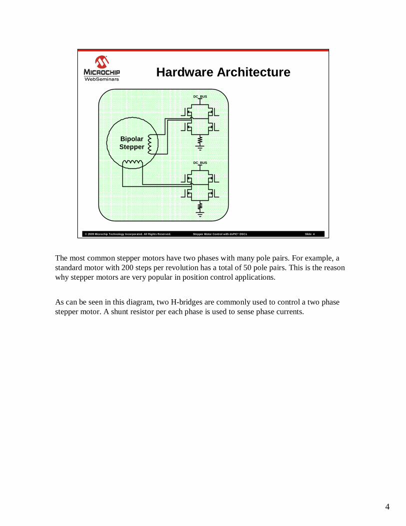
The most common stepper motors have two phases with many pole pairs. For example, a standard motor with 200 steps per revolution has a total of 50 pole pairs. This is the reason why stepper motors are very popular in position control applications.
As can be seen in this diagram, two H-bridges are commonly used to control a two phase stepper motor. A shunt resistor per each phase is used to sense phase currents.
5
© 2009 Microchip Technology Incorporated. All Rights Reserved. Stepper Motor Control with dsPICStepper Motor Control with dsPIC ®® DSCsDSCs Slide 5
Hardware Architecture
BipolarStepper
DC_BUS
DC_BUS
dsPIC
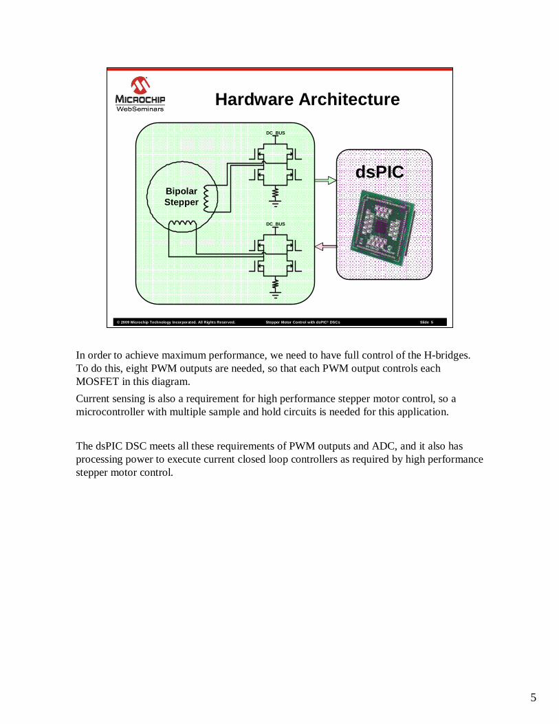
In order to achieve maximum performance, we need to have full control of the H-bridges. To do this, eight PWM outputs are needed, so that each PWM output controls each MOSFET in this diagram.
Current sensing is also a requirement for high performance stepper motor control, so a microcontroller with multiple sample and hold circuits is needed for this application.
The dsPIC DSC meets all these requirements of PWM outputs and ADC, and it also has processing power to execute current closed loop controllers as required by high performance stepper motor control.

6
© 2009 Microchip Technology Incorporated. All Rights Reserved. Stepper Motor Control with dsPICStepper Motor Control with dsPIC ®® DSCsDSCs Slide 6
Decay Modes
In this section we will review different decay modes.
7
© 2009 Microchip Technology Incorporated. All Rights Reserved. Stepper Motor Control with dsPICStepper Motor Control with dsPIC ®® DSCsDSCs Slide 7
DC_BUS
Q1A
Q1B
Q2A
Q2B
Decay Modes
PWM1H1
PWM1L1
PWM1H2
PWM1L2
CurrentDrive
Driv
e
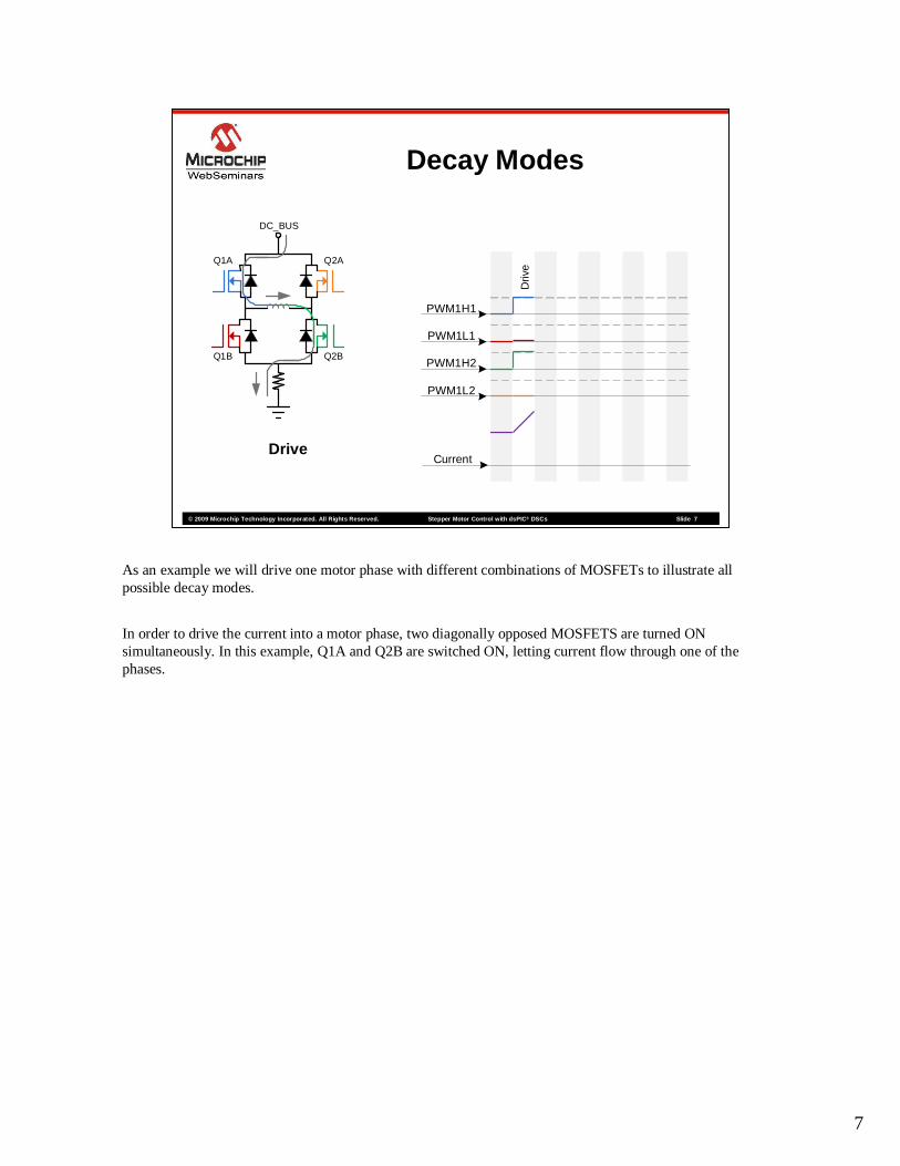
As an example we will drive one motor phase with different combinations of MOSFETs to illustrate all possible decay modes.
In order to drive the current into a motor phase, two diagonally opposed MOSFETS are turned ON simultaneously. In this example, Q1A and Q2B are switched ON, letting current flow through one of the phases.
8
© 2009 Microchip Technology Incorporated. All Rights Reserved. Stepper Motor Control with dsPICStepper Motor Control with dsPIC ®® DSCsDSCs Slide 8
DC_BUS
Q1A
Q1B
Q2A
Q2B
Decay Modes
PWM1H1
PWM1L1
PWM1H2
PWM1L2
CurrentFast Decay
Driv
e
Fas
t D
ecay
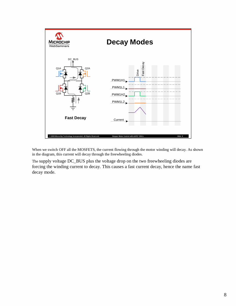
When we switch OFF all the MOSFETS, the current flowing through the motor winding will decay. As shown in the diagram, this current will decay through the freewheeling diodes.
The supply voltage DC_BUS plus the voltage drop on the two freewheeling diodes are forcing the winding current to decay. This causes a fast current decay, hence the name fast decay mode.

9
© 2009 Microchip Technology Incorporated. All Rights Reserved. Stepper Motor Control with dsPICStepper Motor Control with dsPIC ®® DSCsDSCs Slide 9
DC_BUS
Q1A
Q1B
Q2A
Q2B
Decay Modes
PWM1H1
PWM1L1
PWM1H2
PWM1L2
CurrentReverse Decay
Driv
e
Fas
t D
ecay
Rev
erse
Dec
ayA variation of the fast decay mode, called reverse decay, is presented in this slide. This decay mode is used to reduce power dissipation during freewheeling. Instead of letting freewheeling current flow through the diodes, the corresponding MOSFETs are turned ON as shown. The dissipated power will be lower since the MOSFET on-resistance is lower than the diode’s forward resistance.
Notice how current decay rate is slightly lower than fast decay.
10
© 2009 Microchip Technology Incorporated. All Rights Reserved. Stepper Motor Control with dsPICStepper Motor Control with dsPIC ®® DSCsDSCs Slide 10
DC_BUS
Q1A
Q1B
Q2A
Q2B
Decay Modes
PWM1H1
PWM1L1
PWM1H2
PWM1L2
CurrentDrive
Driv
e
Fas
t D
ecay
Rev
erse
Dec
ay
Driv
e
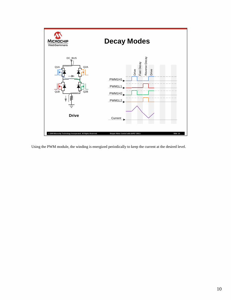
Using the PWM module, the winding is energized periodically to keep the current at the desired level.
11
© 2009 Microchip Technology Incorporated. All Rights Reserved. Stepper Motor Control with dsPICStepper Motor Control with dsPIC ®® DSCsDSCs Slide 11
DC_BUS
Q1A
Q1B
Q2A
Q2B
Decay Modes
PWM1H1
PWM1L1
PWM1H2
PWM1L2
CurrentSlow Decay
High Diode Recirculation
Driv
e
Fas
t D
ecay
Rev
erse
Dec
ay
Driv
e
Slo
w D
ecay
Hig
h D
iode
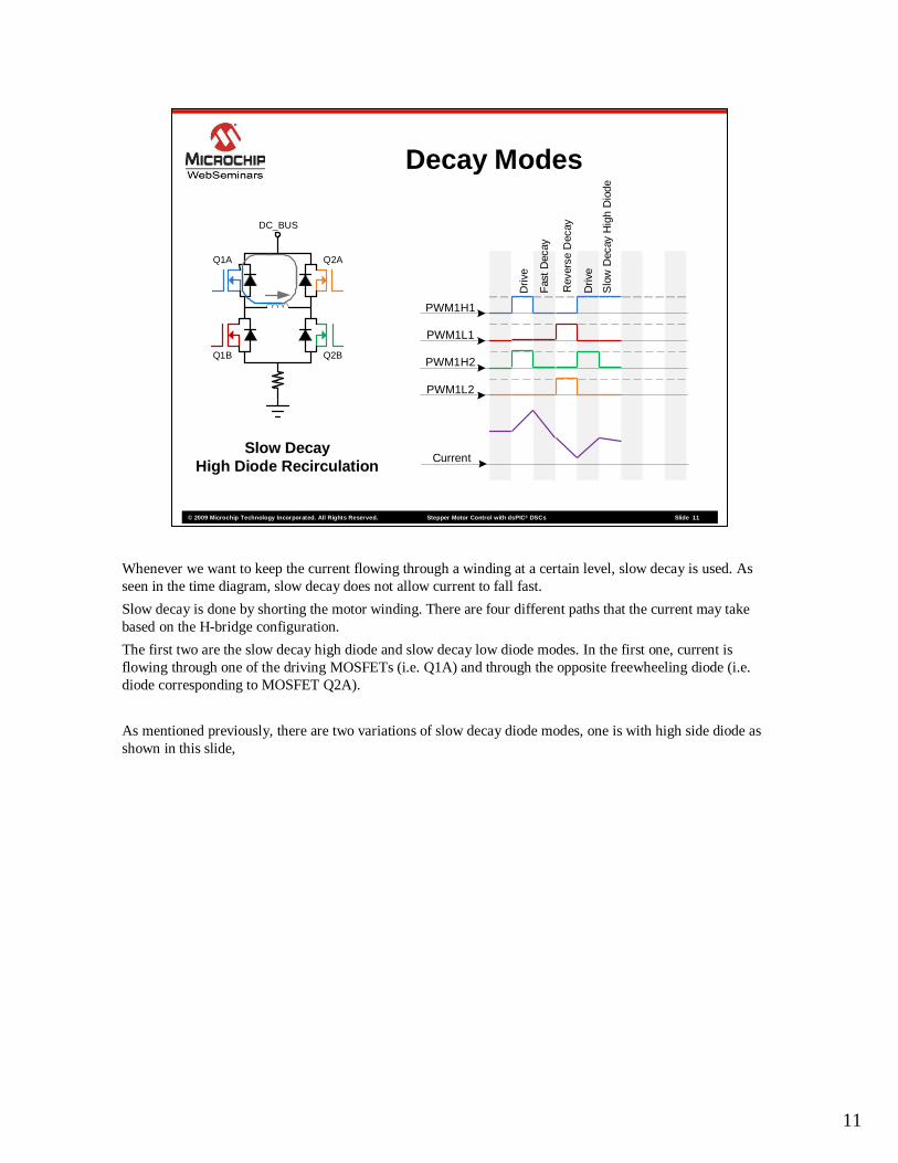
Whenever we want to keep the current flowing through a winding at a certain level, slow decay is used. As seen in the time diagram, slow decay does not allow current to fall fast.
Slow decay is done by shorting the motor winding. There are four different paths that the current may take based on the H-bridge configuration.
The first two are the slow decay high diode and slow decay low diode modes. In the first one, current is flowing through one of the driving MOSFETs (i.e. Q1A) and through the opposite freewheeling diode (i.e. diode corresponding to MOSFET Q2A).
As mentioned previously, there are two variations of slow decay diode modes, one is with high side diode as shown in this slide,
12
© 2009 Microchip Technology Incorporated. All Rights Reserved. Stepper Motor Control with dsPICStepper Motor Control with dsPIC ®® DSCsDSCs Slide 12
DC_BUS
Q1A
Q1B
Q2A
Q2B
Decay Modes
PWM1H1
PWM1L1
PWM1H2
PWM1L2
CurrentSlow Decay
Low Diode Recirculation
Driv
e
Fas
t D
ecay
Rev
erse
Dec
ay
Driv
e
Slo
w D
ecay
Hig
h D
iode
Slo
w D
ecay
Low
Dio
de
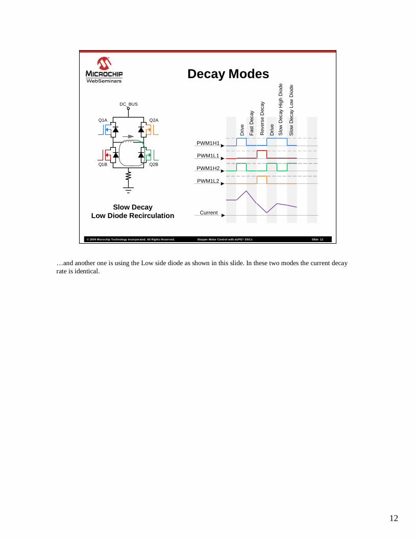
…and another one is using the Low side diode as shown in this slide. In these two modes the current decay rate is identical.
13
© 2009 Microchip Technology Incorporated. All Rights Reserved. Stepper Motor Control with dsPICStepper Motor Control with dsPIC ®® DSCsDSCs Slide 13
DC_BUS
Q1A
Q1B
Q2A
Q2B
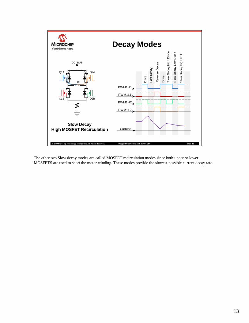
Decay Modes
PWM1H1
PWM1L1
PWM1H2
PWM1L2
CurrentSlow Decay
High MOSFET Recirculation
Driv
e
Fas
t D
ecay
Rev
erse
Dec
ay
Driv
e
Slo
w D
ecay
Hig
h D
iode
Slo
w D
ecay
Low
Dio
de
Slo
w D
ecay
Hig
h F
ET
The other two Slow decay modes are called MOSFET recirculation modes since both upper or lower MOSFETS are used to short the motor winding. These modes provide the slowest possible current decay rate.

14
© 2009 Microchip Technology Incorporated. All Rights Reserved. Stepper Motor Control with dsPICStepper Motor Control with dsPIC ®® DSCsDSCs Slide 14
DC_BUS
Q1A
Q1B
Q2A
Q2B
Decay Modes
PWM1H1
PWM1L1
PWM1H2
PWM1L2
CurrentSlow Decay
Low MOSFET Recirculation
Driv
e
Fas
t D
ecay
Rev
erse
Dec
ay
Driv
e
Slo
w D
ecay
Hig
h D
iode
Slo
w D
ecay
Low
Dio
de
Slo
w D
ecay
Hig
h F
ET
Slo
w D
ecay
Low
FE
T
The low MOSFET recirculation mode is the most commonly used for slow decay mode. This is because in a standard bootstrap H-bridge configuration it is important to have the lower MOSFETs ON as much as possible to recharge the bootstrap capacitors.
15
© 2009 Microchip Technology Incorporated. All Rights Reserved. Stepper Motor Control with dsPICStepper Motor Control with dsPIC ®® DSCsDSCs Slide 15
Microstepping
In this section of the web seminar, different microstepping methods will be discussed.
16
© 2009 Microchip Technology Incorporated. All Rights Reserved. Stepper Motor Control with dsPICStepper Motor Control with dsPIC ®® DSCsDSCs Slide 16
Microstepping
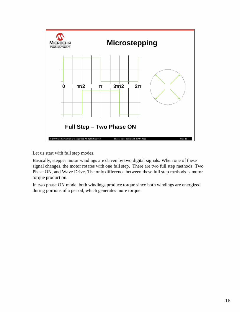
Full Step – Two Phase ON
0 π/2 π 3π/2 2π
Let us start with full step modes.
Basically, stepper motor windings are driven by two digital signals. When one of these signal changes, the motor rotates with one full step. There are two full step methods: Two Phase ON, and Wave Drive. The only difference between these full step methods is motor torque production.
In two phase ON mode, both windings produce torque since both windings are energized during portions of a period, which generates more torque.
17
© 2009 Microchip Technology Incorporated. All Rights Reserved. Stepper Motor Control with dsPICStepper Motor Control with dsPIC ®® DSCsDSCs Slide 17
Microstepping
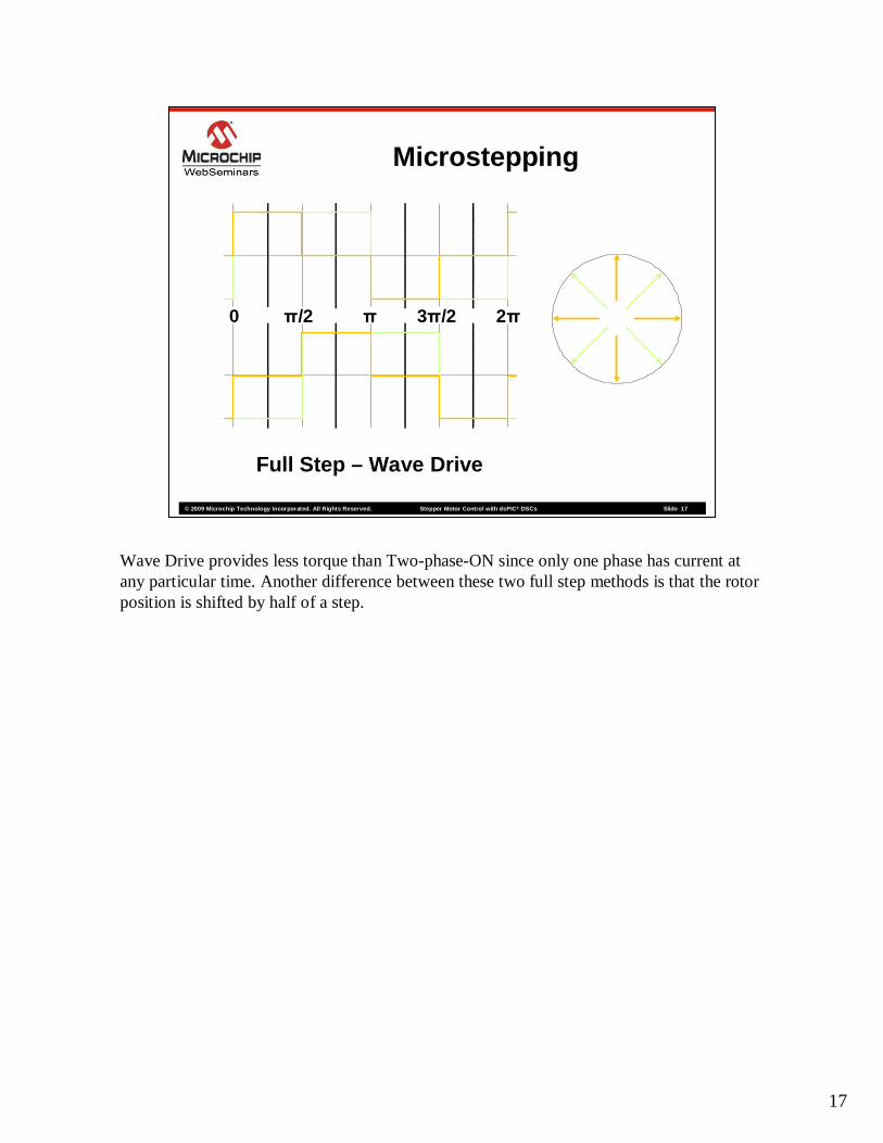
Full Step – Wave Drive
0 π/2 π 3π/2 2π
Wave Drive provides less torque than Two-phase-ON since only one phase has current at any particular time. Another difference between these two full step methods is that the rotor position is shifted by half of a step.
18
© 2009 Microchip Technology Incorporated. All Rights Reserved. Stepper Motor Control with dsPICStepper Motor Control with dsPIC ®® DSCsDSCs Slide 18
Microstepping
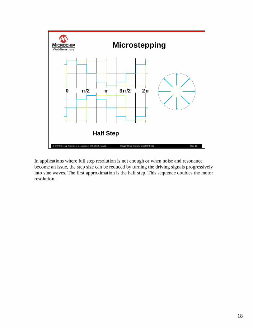
Half Step
0 π/2 π 3π/2 2π
In applications where full step resolution is not enough or when noise and resonance become an issue, the step size can be reduced by turning the driving signals progressively into sine waves. The first approximation is the half step. This sequence doubles the motor resolution.
19
© 2009 Microchip Technology Incorporated. All Rights Reserved. Stepper Motor Control with dsPICStepper Motor Control with dsPIC ®® DSCsDSCs Slide 19
Microstepping
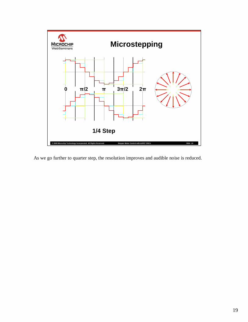
1/4 Step
0 π/2 π 3π/2 2π
As we go further to quarter step, the resolution improves and audible noise is reduced.
20
© 2009 Microchip Technology Incorporated. All Rights Reserved. Stepper Motor Control with dsPICStepper Motor Control with dsPIC ®® DSCsDSCs Slide 20
Microstepping
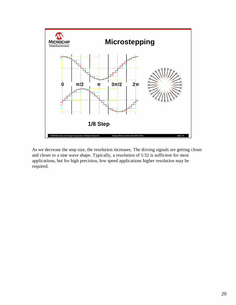
1/8 Step
0 π/2 π 3π/2 2π
As we decrease the step size, the resolution increases. The driving signals are getting closer and closer to a sine wave shape. Typically, a resolution of 1/32 is sufficient for most applications, but for high precision, low speed applications higher resolution may be required.

21
© 2009 Microchip Technology Incorporated. All Rights Reserved. Stepper Motor Control with dsPICStepper Motor Control with dsPIC ®® DSCsDSCs Slide 21
Open Loop Current Control
In this section of the web seminar, Open Loop Current Control will be discussed.
22
© 2009 Microchip Technology Incorporated. All Rights Reserved. Stepper Motor Control with dsPICStepper Motor Control with dsPIC ®® DSCsDSCs Slide 22
Open Loop Current Control
Current
Voltage
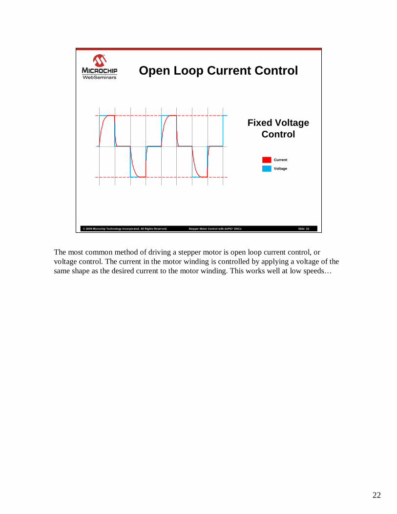
Fixed VoltageControl
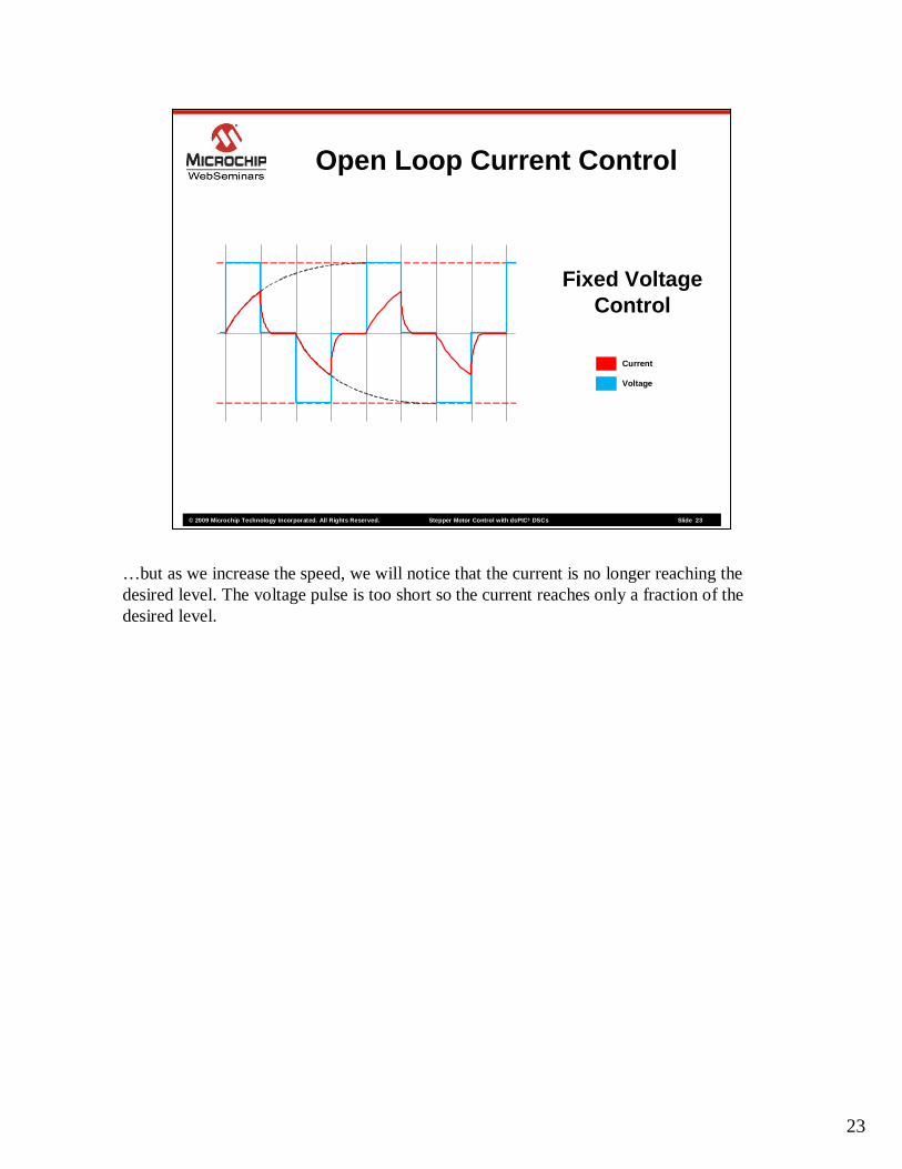
The most common method of driving a stepper motor is open loop current control, or voltage control. The current in the motor winding is controlled by applying a voltage of the same shape as the desired current to the motor winding. This works well at low speeds…
23
© 2009 Microchip Technology Incorporated. All Rights Reserved. Stepper Motor Control with dsPICStepper Motor Control with dsPIC ®® DSCsDSCs Slide 23
Open Loop Current Control
Current
Voltage
Fixed VoltageControl
…but as we increase the speed, we will notice that the current is no longer reaching the desired level. The voltage pulse is too short so the current reaches only a fraction of the desired level.

24
© 2009 Microchip Technology Incorporated. All Rights Reserved. Stepper Motor Control with dsPICStepper Motor Control with dsPIC ®® DSCsDSCs Slide 24
Open Loop Current Control
Current
Voltage
Fixed CurrentControl
To overcome this problem, we increase the driving voltage to a level that allows the desired current level to be reached in the available time. The current rises following the dotted path as forced by the new voltage. Notice that only the voltage amplitude is changed, not the shape. The current waveform resembles a saw-tooth rather than the desired square-wave. Voltage control alone cannot help solving this problem.
25
© 2009 Microchip Technology Incorporated. All Rights Reserved. Stepper Motor Control with dsPICStepper Motor Control with dsPIC ®® DSCsDSCs Slide 25
Current
Voltage
Slow Decay
Fast Decay
Fixed Decay
Open Loop Current Control
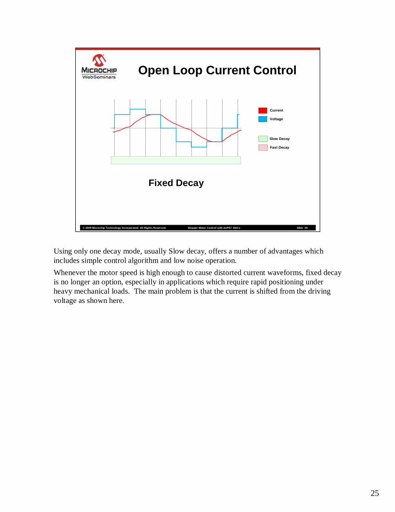
Using only one decay mode, usually Slow decay, offers a number of advantages which includes simple control algorithm and low noise operation.
Whenever the motor speed is high enough to cause distorted current waveforms, fixed decay is no longer an option, especially in applications which require rapid positioning under heavy mechanical loads. The main problem is that the current is shifted from the driving voltage as shown here.
26
© 2009 Microchip Technology Incorporated. All Rights Reserved. Stepper Motor Control with dsPICStepper Motor Control with dsPIC ®® DSCsDSCs Slide 26
Current
Voltage
Slow Decay
Fast Decay
Open Loop Current Control
Alternate Decay
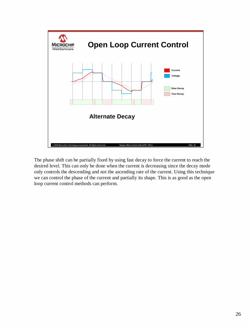
The phase shift can be partially fixed by using fast decay to force the current to reach the desired level. This can only be done when the current is decreasing since the decay mode only controls the descending and not the ascending rate of the current. Using this technique we can control the phase of the current and partially its shape. This is as good as the open loop current control methods can perform.
27
© 2009 Microchip Technology Incorporated. All Rights Reserved. Stepper Motor Control with dsPICStepper Motor Control with dsPIC ®® DSCsDSCs Slide 27
Closed Loop Current Control
Closed Loop Current Control will be discussed next.
28
© 2009 Microchip Technology Incorporated. All Rights Reserved. Stepper Motor Control with dsPICStepper Motor Control with dsPIC ®® DSCsDSCs Slide 28
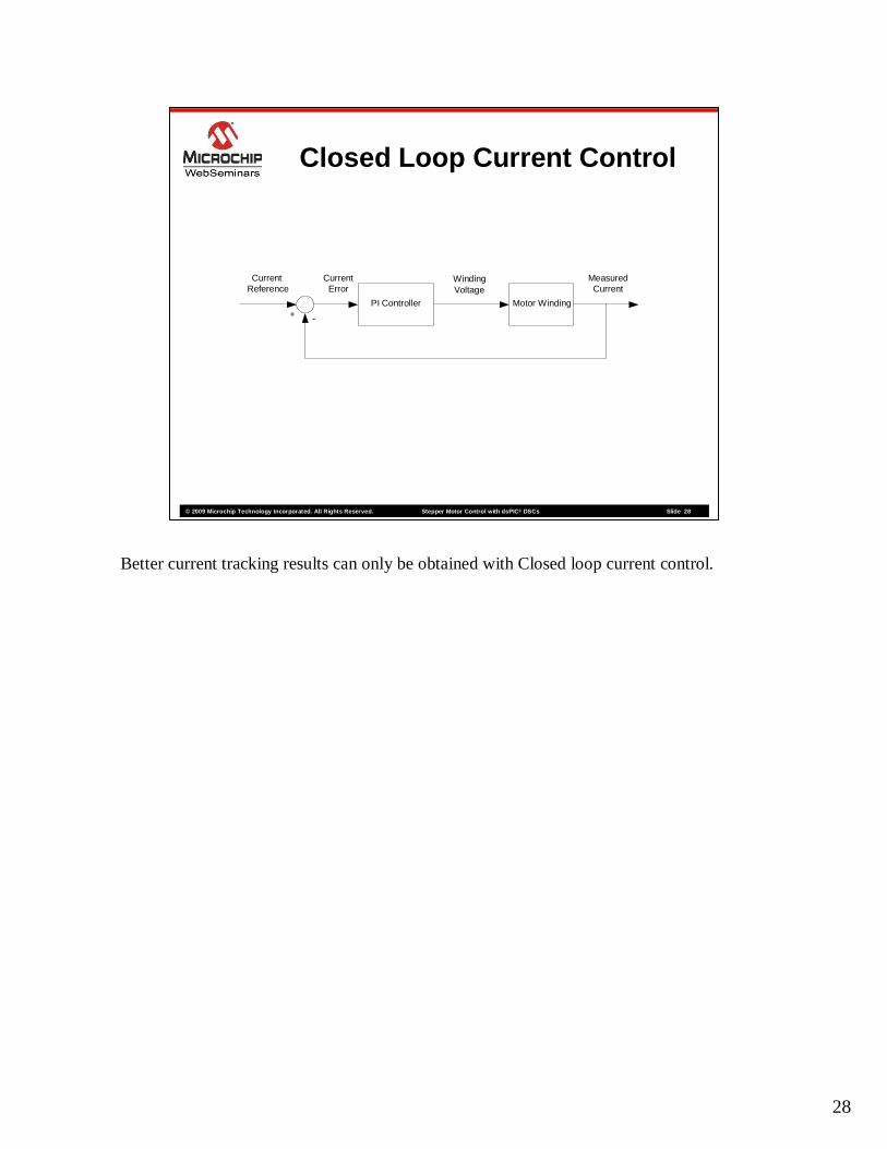
Closed Loop Current Control
Winding Voltage
CurrentReference
+ -
CurrentError
MeasuredCurrent
Motor WindingPI Controller
Better current tracking results can only be obtained with Closed loop current control.
29
© 2009 Microchip Technology Incorporated. All Rights Reserved. Stepper Motor Control with dsPICStepper Motor Control with dsPIC ®® DSCsDSCs Slide 29
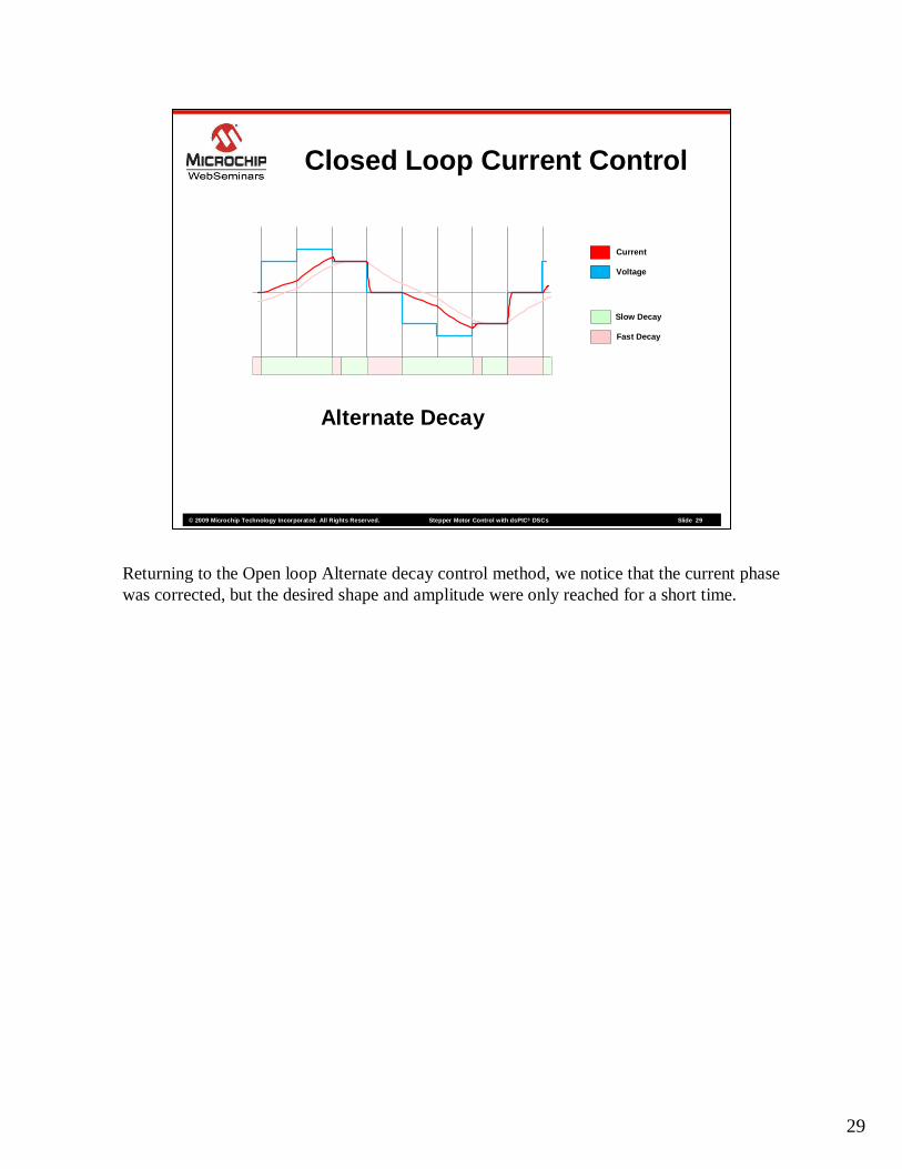
Current
Voltage
Slow Decay
Fast Decay
Alternate Decay
Closed Loop Current Control
Returning to the Open loop Alternate decay control method, we notice that the current phase was corrected, but the desired shape and amplitude were only reached for a short time.

30
© 2009 Microchip Technology Incorporated. All Rights Reserved. Stepper Motor Control with dsPICStepper Motor Control with dsPIC ®® DSCsDSCs Slide 30
Current
Voltage
Slow Decay
Fast Decay
Closed Loop Current Control
Closed loop Current Control manages to control the amplitude, shape and phase of the winding current at the same time. As long as the drive voltage is large enough to allow a rise time shorter than the step time, the current will follow the desired waveform.
Slow decay is used as much as possible since it provides minimum power loss as well as low noise operation. Fast Decay is mostly used to allow fast current decay rates. The PI controller implemented on the dsPIC has full control of the decay modes and it decides when to switch from Slow Decay to Fast Decay, or vice-versa.
31
© 2009 Microchip Technology Incorporated. All Rights Reserved. Stepper Motor Control with dsPICStepper Motor Control with dsPIC ®® DSCsDSCs Slide 31
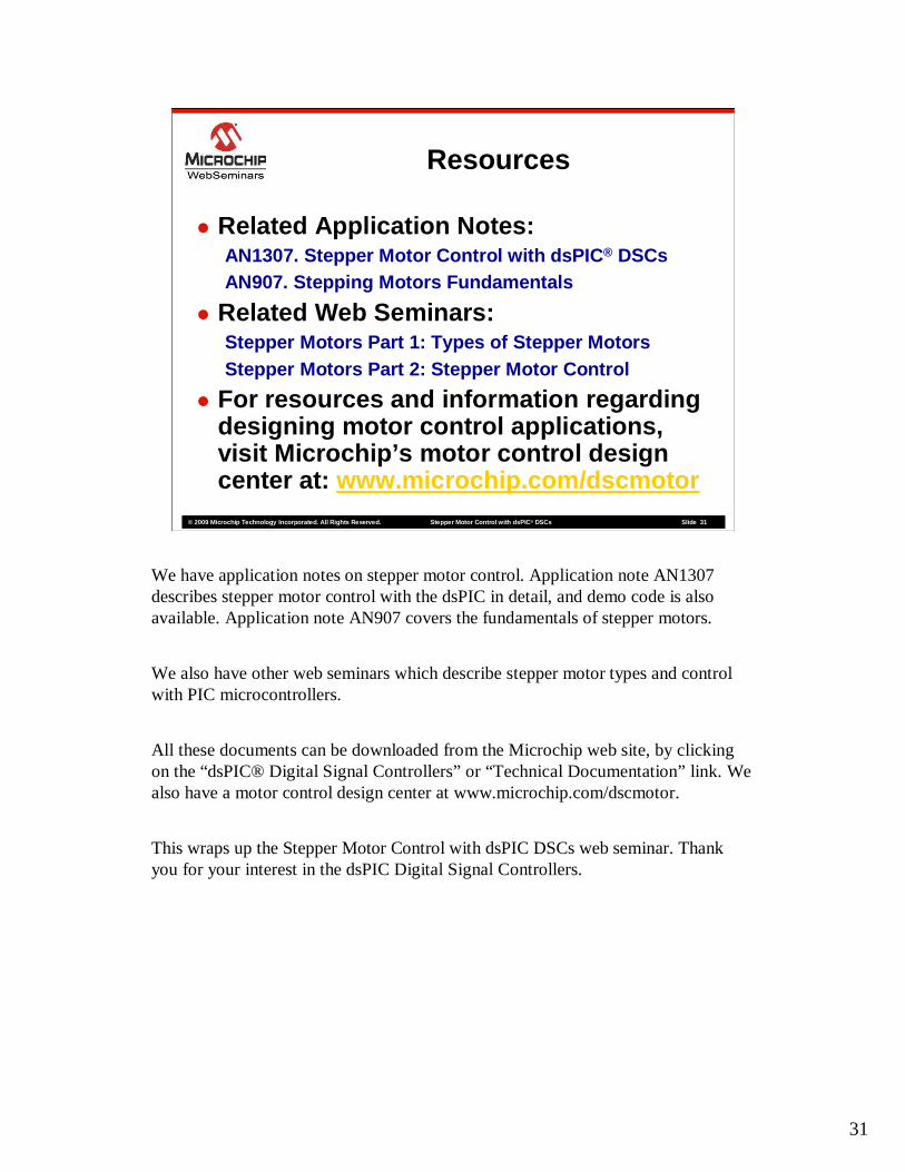
Resources
� Related Application Notes:AN1307. Stepper Motor Control with dsPIC ® DSCsAN907. Stepping Motors Fundamentals
� Related Web Seminars:Stepper Motors Part 1: Types of Stepper MotorsStepper Motors Part 2: Stepper Motor Control
� For resources and information regarding designing motor control applications, visit Microchip’s motor control design center at: www.microchip.com/dscmotor
We have application notes on stepper motor control. Application note AN1307 describes stepper motor control with the dsPIC in detail, and demo code is also available. Application note AN907 covers the fundamentals of stepper motors.
We also have other web seminars which describe stepper motor types and control with PIC microcontrollers.
All these documents can be downloaded from the Microchip web site, by clicking on the “dsPIC® Digital Signal Controllers” or “Technical Documentation” link. We also have a motor control design center at www.microchip.com/dscmotor.
This wraps up the Stepper Motor Control with dsPIC DSCs web seminar. Thank you for your interest in the dsPIC Digital Signal Controllers.


