
STUDIES ON RARE EARTH DOPED NICKEL FERRITE Chapter V
Bnl L The nickel A samples were prepared as described in chapter II.
The nickel ferrite samples of composition NixFe3.x04 of concentrations x = 0.3,
0.5, 0.7 and 0.9 were taken. The samples were doped with neodymium and
gadolinium 5% (weight I weight).
5.1 Structural Studies By X Ray Diffraction
The X-ray diffraction of Nio3Fe2,04 doped with ~ d ~ ' and Gd3' is shown
in figures [5.1 . I &5.1.2]. It exhibits cubic spinel structure for all the samples of
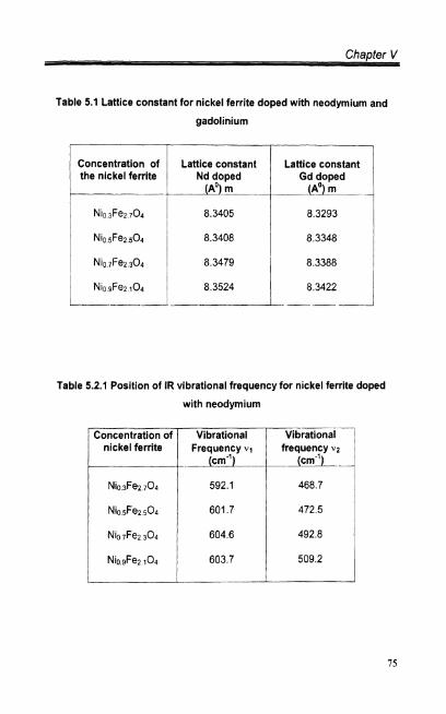
the series Ni,Fe3x04 of Fd3m space group. It is clear from the table [5.1] that
the lattice parameter goes on increasing w~th the Increase in nickel content in
the series Ni,Fe3.,04. The observed increase in the 'a' with the increase in
concentration can be explained on the basis of ionic radi~ of the rare earth ions
substitution and distribution in the structure. Both ~ d ~ ' and Gd3' ions prefer
octahedral site (B-site) and replace ~ e ~ ' Ion in the splnel structure. Since ~ e ~ '
ions are being replaced by the bigger ions ~ d ~ ' and Gd3', the increase in 'a' is
obvious. The occupancy of ~ e ~ ' ions by rare earth ions in the octahedral site is
explained based on IR spectral studies. Broadening of high and low frequency
bands indicates the rare earth ions in octahedral site.
It was reported [Rezlescu.N et al. (1994), Rez1escu.N et al. (1998), Sattar
A.A et al. (2002) and Hua Yang (1996)l that when some Fe ions in ferrite
lattices are substituted by Gd and Nd ions, the lattice parameters will change.
5.2 Spectral Studies Using FTlR
The IR spectra were recorded using a FTlR Shimadzu 8700
model. IR spectrophotometer in the range of 1000-400 cm" at RT. In
recording IR spectra, each of the samples was mixed with potassium bromide
powder and pressed into pellets. The procedure for making KBr pellets was as

Chapter V
discussed in the previous chapter. The infrared spectra of all the rare earth
mixed Ni ferrites are shown in Figs. (5.2.1 8 5.2.2). The absorption band v,,
observed at around 590cm-' is due to metal oxygen stretching vibrational
modes and it is attributed to F$-0' vibrations at the tetrahedral slte, whereas
v 2 observed at 470cm-' is assigned to octahedral F ~ ~ ' - o ~ - group complexes
[Josyulu 0.S et.al (1981)l. Spectral bands of the and Gd3' doped nickel
ferrite samples are glven in the tables (5.2.1, 5.2.21. For gadolinium doped
nickel ferrlte, bands are observed in the range 550,470cm-'. It is found that the
positions of bands are composition dependent. The bands observed in this
range are weak in intensity for both the dopants. The bands are broadened due
to the addition ~ d ~ ' and Gd3' in the nickel ferrite samples. This fact IS also
supported by [C M Sr~vastav et al. (1982)]. On substitution of ~ d ~ ' and Gd3',
the position of v2 band shifts towards lower side, as compared to undoped
samples. Which suggests the occupancy of ~ d ~ ' & Gd3' at Octahedral (B) site.
However, on substitution of impurities as said before, broadening of v2 band
takes place which may be due to occupancy of cations of different character on
the same site. The vibrational frequency v for the diatomic molecule IS given
by the relation
11 = Vibrational frequency of the ion
K = force constant of the ion
M = reduced mass of the ion
The decrease in vibrational frequencies indicates that the bond length
decreases. It is found to decrease the octahedral force constant, which
supports the occupancy of neodymium and gadolinium on B site. The
compositional dependent behaviour of force constant is attributed to the cation
oxygen bond distances [C.B Kolekar et al. (1994 )] Though the d~atomic

approximation is quite good, one can get only qualitative information using this.
The vibrational modes of the unit cell will be the more accurate one.
The IR absorption bands of solids in the range 100- 1000 cm-' are
usually assigned to vibrations of ions in the crystal lattice [Brabers V.A.M
(1969)l. According to [Waldron(1955)], the ferrites can be considered
continuously bonded crystals, meaning that the atoms are bonded to all nearest
neighbours by equivalent forces (ionic, covalent or Van der Waals). The
frequency distribution of vibrations is given by a Debye treatment of the
classical mechanical problem. In ferrites the metal ions are situated in two
different sublattices designated tetrahedral (A site) and octahedral (Bsite)
according to the geometrical configuration of the oxygen nearest neighbours. [
Waldron1955 ] and [ Hafner 1961 ] have attributed the band around 600 cm-' to
stretching vibrations of the tetrahedral groups (v l ) and around 400 cm-' to the
octahedral groups (v2 ).
Barbers and Vandengerh (1973) have shown that the fine structure In the
IR spectrum can be considered indicative of the presence of crystallographic
ordering. In the IR spectra of the Li05+~ rxTix Fez 5.1 5 x 0 4 composition, the fine
structure is much less pronounced with Increasing titanium concentration. It can
be inferred that the weak fine structure in the IR spectra IS correlated with this
short-range order. The gradual weakening of the fine structure in the IR spectra
with increasing Ti content indicates that long-range order transforms more and
more into short-range order. It can be considered that the symmetry of the
crystal is lowered as a result of the loss of long-range order. This result will be
reflected in the magnetic properties such as the magnetization and the Curie
point. The results concerning this have been published recently [Mazen S A et
al. (1996)l. In the composition of Zn-Mg ferrite doped with Nd ions, the position
of v2 band shifts towards lower side, which suggests the occupancy of ~ d ~ ' ion
on octahedral (B) site. The results regarding DC electrical resistivity study
support the B-Site occupancy of Nd and it shows increase in the DC resistivity

due to its impediment to the electrical conduction [Ladgaonkar et al. 20011 The
magnetization study also supports the occupancy of neodym~um ion on 0- s~te
showing dilution in the magnetization [Ladgaonkar et al. 2000al. However, on
Nd3+ ion substitution, the broadening of v2 band takes place, which may be due
to occupancy of cations of different characters on the same site [Kolekar et al.
19941.
5.3 Magnetic Studies Using Vibrating Sample Magnetometer
The magnetization recording technique using VSM is same as discussed
in the previous chapter at RT.
5.3.1 Saturation Magnetization
The saturation magnetization was found to be lncreaslng with the
concentration as shown in flg(5.3.1). From the table [5.3] it is evident that for
~ d ~ ' d o p e d nickel ferrite M, value increases from 11 emulg to 24emu/g, where
as for Nd3' doped sample it increases from 12 emulg to 26 emulg. The lower
value of magnetization for Gd doped samples may be explained as follows: The
magnetic moment of ~ d ~ ' is 7.94~0, whereas for Nd3' ~t is 3 . 5 ~ 0 . As the net
magnetization is due to antiferromagnetic alignment, the Gd3' doped samples
will have smaller magnetization compared to Nd3' doped samples. Thus, the
sample doped with neodymium has less magnetization compared to gadol~nium
doped sample. It was reported earlier by Lijun Zhao et a1.(2006) that the
saturation magnetization for Nio-lMno3GdxFe2.x04 (Ni-Mn ferr~te doped with Gd),
the values are close to the undoped sample at 800' and 850°c. When the
crystallite sizes are about 30- 40 nm, the samples have similar M, values. This
may be due to the following facts. The magnetic moment of Gd ions is 7.94118,
and Gd is the only rare earth element that has a curie temperature T, (293.3K)
close to room temperature. When the Fe ions are substituted by Gd ions at

Chapter V
lattice sites, the rare earth ion interactions are stronger than Fe-Fe interactions,
so the M, may be increased siginificantly. But as the Gd doped content is less
than 10% of Fe content, the microsubstitution is not enough to increase the
saturation magnetization siginificantly. When the contents of the Gd ions
increase, the doped Gd ions cannot enter into the ferrite lattice totally, as the
ionic radii of the ~ d ~ ' ions are larger than those of ~ e ~ ' ions. Hence the Fe-Fe
~nteractions decrease due to the reduction in the concentration of Fe ions on
the B- sites. All the explanations are based on the assumption that the rare
earth ions occupy the B-sites [HuaYang et al. (2004)l. This fact is in support of
the present observation.
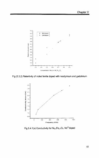
5.3.2 Retentivity
The effect of retentivity with the composition of the nickel ferrite is shown
in fig(5.3.2). The M, values are presented in the table [5.3], which shows the
Increase M, for increase in concentration of nickel in nickel ferrite for both Nd
and Gd doped ferrite. For Nd doped nickel ferrite, the retentivity increases from
3.30 to 5.1 lemulg and for Gd it is 2.99-5.03 emulg. Substitution of rare earth
ions has not significantly changed the retentivity when compared to the
undoped samples as shown in (table 4.3 and 5.3) .
5.4 Electrical Studies
The AC electrical conductivity studies are done using LCZ Zentech 3305
Automatic Component Analyzer at RT. The preparation of the sample is same
as that in the previous chapter. The variation of conductivity with the applied
ac frequency is shown in figures 5.4.l(a-d) and 5.4.2(a-d).

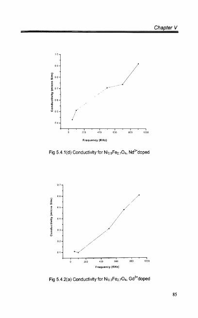
5.4.1 Electrical Conductivity
The AC electrical conductivity is measured at different frequencies for Nd
and Gd doped nickel ferrite. They are shown in tables [5.4.1 & 5.4.21 and the
variation of conductivity with frequency is shown in figures 5.4.l(a-d) & 5.4.2(a-
d). AC conductivity increases with the increase of frequency. At lower
frequencies conductivity is independent up to 100KHz. Doping of these
samples wlth neodymium I gadolinium has a strong influence on the
conductivity. In all the samples the conductivity of neodymium doped samples is
higher than gadolinium doped samples. The higher magnitude in neodymium
doped sample may be expla~ned as follows: Neodymium has four unpaired
electrons in the 4f orbital whlch contributes to the conductivity whereas
gadolinium has one electron in 5d orbital whlch contributes to conductivity to a
smaller extent [ M.A.Ahmed et al. (2003) 1. A small change In the interactions
between the Gd I Nd ions with nickel Ions can cause a change in the
conductivity. In this case the conductivity of the both samples is low with a
magnitude of about 1pSeimenslm at 9OOKHz
The frequency dependence of AC electrical conductivity of the Ni -Mg
ferrite sample is reported by L.John Brechmans et al. (2004). It IS observed that
the AC conductivity Increases with increasing applied frequency. Since the
increase In frequency enhances the hopping frequency of the charge carriers
Fez' and ~ e ~ ' the conduction is increased. The conduction mechanism of
ferrite is explained on the basis of hopping of charge carriers between ~ e ' ' and
Fe3' on the octahedral sites. The present findings of increase in conductivity
with frequency are supported by this report
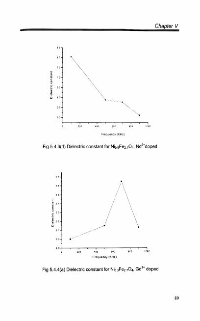
5.4.2 Dielectric Constant
Doping of these samples with Nd IGd the dielectric constant decreases
with the frequency and composition. Tables [5.5.land 5.5.21 and figures
5.4.3(a-d) 8. 5.4.4(a-d) represent these data. The dielectric properties may be
explained in terms of the assumption that the mechanism of dielectric
polarization is similar to that of conduction (that it depends depends on the
charge carriers). Since the rare earth ions radii are large compared to that of
the Ni. Fe. The occupancy of Nd3' I Gd3+ into the octahedral sites is probable.
The dielectric polarization depends on number ferrous ions which take part in
the electron exchange interaction. Thus the dielectric polarization is decreasing
which tends to decrease dielectric properties.
An similar explanation was proposed by [Reddy and Rao 19821 for Li -TI
ferrites. They reported that the electron exchange interactions [Waldron RD
19551 result in a local displacement of electrons in the directions of the electric
field, which determines the polarization of the ferrites. The ferrous ions which
take part in the electron exchange ~nteraction between Fez' and Fe3' are
formed during the sintering process and their presence is confirmed by IR
absorption spectra. Hence, the presence of Fez+ ions is responsible for the
polarization. The number of ferrous ions decrease and hence, the polarization
decreases. Thus, the number of Fez' ions play a dominant role in the
mechanism of dielectric polar~zation.
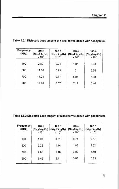
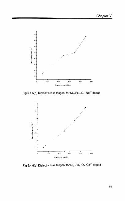
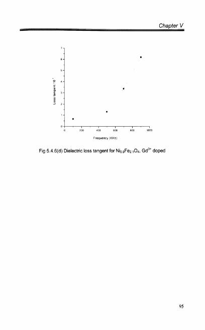
5.4.3 Dielectric Loss Tangent
The variation of loss tangent with frequency of the samples is shown in
the tables [5.6.l.and 5.6.21. From the figure 5.4.5(a-d) & 5.4.6(a-d), it is evident
that dielectric loss tangent increases with the frequency. The dielectric loss
tangent shows a hike at the frequency 500 KHz. This may be due to transfer of
electrons between Fez' and Fe3' and holes between ~ i " and Ni" in octahedral
sites. When compared with ~ d ~ ' , Gd3' doped samples, dielectric loss tangent
for Nd is larger than Gd doped samples. Since the ionic radii of Nd is less than
Gd the higher magnitude of loss tangent is seen in Nd doped samples.
The variation of loss tangent with frequency for the Ni- Mg ferrite
samples was reported earlier. An abnormal dielectric behaviour IS observed for
all the samples because the d~electric relaxation peaks are observed at a
frequency of 2KHz. According to Rezlescu model, the relaxation peaks may be
due to the collective contribution of both p and n type of charge carriers
[N.Rezlescu (1974)l. The electronic exchange between between ~ e ' ' and ~ e ~ '
and hole transfer between Ni2' and Ni3' in octahedral sttes are responsible for
such behaviour. Further the jumplng frequencies of localtzed charge carriers
are almost equal to those of the AC electric f~eld at the peak. However, in the
present case there is only an increase in loss tangent with the frequency.

Chapter V
Table 5.1 Lattice constant for nickel ferrite doped with neodymium and
gadolinium
the nickel ferrite
Table 5.2.1 Position of IR vibrational frequency for nickel ferrite doped
with neodymium
- Concentration of T T i k a X n a i Vibrational 1 nickel ferrite Frequency V, frequency v 2
( 1 --led. -

Table 5.2.2 Position of IR vibrational frequency of nickel ferrite doped
with gadolinium
Concentration of nickel ferrite
Vibrational Vibrational Frequency frequency
.l (cm") VI (cm-') -- - - --
Table 5.3 Saturation magnetization and Retentivity of nickel ferrite doped
with neodymium and gadolinium
-- I Concentration [;;r;rt -I ~ a t i r a t i o r 1 of the nickel magnetization magnetization 1 ferrite Neodymium gadolinium
doped emulg doped
t- emulg
1 Nb3Fez704 11 31

Table 5.4.1 Conductivity of nickel ferrite doped with neodymium
Table 5.4.2 Conductivity of nickel ferrite doped with gadolinium

Chaoter V
Table 5.5.1 Dielectric constant of nickel ferrite doped with neodymium
Table 5.5.2 Dielectric constant of nickel ferrite doped with gadolinium
Chapter V
Table 5.6.1 Dielectric Loss tangent of nickel ferrite doped with neodymium
t a n
, i (Nio sFez ~ 0 4 ) (Nio 7Fe2
lo3
Table 5.6.2 Dielectric Loss tangent of nickel ferrite doped with gadolinium
- -
q u e n c y tan 6 1 tan b
(KHz) ' (Nio 3Fe27Od (Nio 5F.2 504) (Nil 7Fe2 304) (Nio .Fez 104) ---p.? 3 o3


Fig (5.1 .I ) XRD pattern for Nio 3Fe2 7 0 4 doped with neodymium
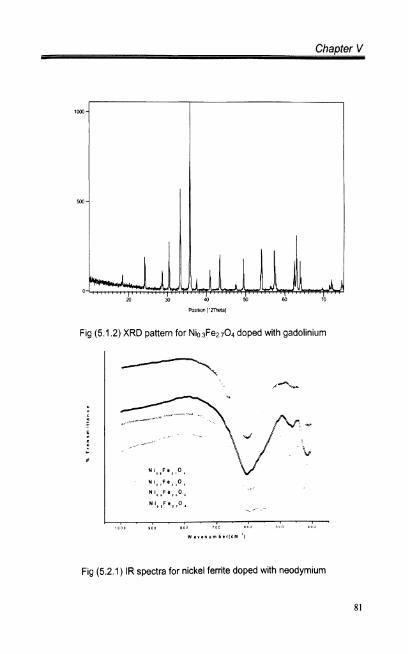
Fig (5.1.2) XRD pattern for Nio 3Fe2704 doped with gadolinium
Fig (5.2.1) IR spectra for nickel ferrite doped with neodymium

Fig (5.2.2) IR spectra for nickel ferr~te doped with gadolin~um
Fig (5.3.1) Saturation magnetization for nickel ferrite doped with neodymium and gadolinium
Chapter V
Fig (5.3.2) Retentlv~ty of nickel ferrite doped with neodymium and gadolinium
I 0
0 8
o 100 100 600 son 1000
Frequency ( K H z )
Fig 5.4.l(a) Conductivity for Nio3Fe2,04, ~ d ~ + d o p e d

Chapter V
I , , , , . , . , 0 200 400 BOD 800 I000
Frequency (KHz)
Fig 5.4 . l (b) Conduct~v~ty for Nio5Fe2 5 0 4 , ~d~'doped
1 0 200 400 600 800 7000
Frequency (KHz)
Fig 5.4.l(c) Conductiv~ty for N I O I F ~ ~ 3 0 4 , ~ d ~ ~ d o p e d
a z o o ,370 a o o 800 ,000
Frequency (KHz)
Fig 5.4.l(d) Conductivity for Ni0gFe2 104, ~ d ~ ~ d o p e d
0 200 do0 600 800 1000
Frequency (KHz)
Fig 5.4.2(a) Conductivity for NiosFe2704, ~ d ~ ~ d o p e d

, , , . , . , . , . I o 200 eoc i nc aco ,roo
Frequency ( K H z )
Fig 5.4.2(b) Conductivity for Nio sFe2 5 0 4 , ~ d ~ + d o ~ e d
Frequency (KHz1
Fig 5.4.2(c) Conductivity for Nio 7Fe2.304, ~ d ~ ' d o ~ e d

Chapter V
/ . I . , , / . , . /
0 200 I O U GOO P O P 10011
Frequency (KHz)
Fig 5.4.2(d) Conductivity for NiogFe2 1 0 4 , ~ d ~ + d o p e d
Frequency (KHz)
Fig 5.4.3(a) Dielectric constant for Nio ,Fez 7 0 4 , ~ d ~ ~ d o p e d

, , . , . , , , I ,
0 200 400 600 800 1000
Frequency (KHz)
Fig 5.4.3(c) Dielectric constant for N I ~ ,Fez 3 0 4
Chapter V
I . , . , . , . , . , 0 200 400 800 800 ?OD0
Fig 5.4.3(d) Dielectric constant for NlosFe2 1 0 4 , ~ d ~ * d o ~ e d
Fig 5.4.4(a) Dielectric constant for Nio 3Fen 7 0 4 , ~ d ~ ' doped
5 7 -
5 6 -
5 5 -
; 5 4 -
0 5 3 -
t 5 2 - 0 .
5 , -
5 0 -
1 9 3
, ,
',
. 1 , . , . , . , . I
0 ?OF 100 500 800 1000
Frequency ( K H z )

0 100 400 600 600 1000
Frequency (KHz)
Fig 5.4.4(b) Dielectric constant for NiosFe2504, Gd3+ doped
" " 0 200 400 600 800 1000
Frequency (KHz)
Fig 5.4.4(c) Dielectric constant for Nio ,Fez 3 0 4 , Gd3* doped

3 1 1 200 103 600 800 ,000
Frequency I K H z j
Fig 5.4.4(d) Dielectric constant for NiogFez 1 0 4 , ~ d ~ ' doped
6 l i -
t ' 0 -
6 -
i - i ' , ~ l ~ ~ ~ ~ ~ ~ 0 >oo 40: 600 800 lo00
Frequency [KHz)
Fig 5.4.5(a) Dielectric loss tangent for Nio fez 7 0 4 , ~d~~ doped

Chapter V
Frequency (KHz)
Fig 5.4.5(b) Dielectric loss tangent for Nio ~Fe2 so4, ~ d ~ ' doped
Frequency (KHz)
Fig 5.4.5(c) Dielectric loss tangent for Nio7Fe2.304, ~ d ~ ' doped
Chapter V
Frequency ( K H z )
Fig 5.4.5(d) Dielectric loss tangent for NiogFe2 1 0 4 , ~ d ~ ' doped
Fig 5.4.6(a) Dielectric loss tangent for Nio,Fe~ 704 Gd3+ doped

Chapter V
400 (10" BOO lO"0
Frequency (KHz]
Fig 5.4.6(b) Dielectric loss tangent for NiosFe2 5 0 4 . Gd3' doped
200 a00 6 0 0 qr 1000
Frequency I K H z I
Fig 5.4.6(c) Dielectric loss tangent for Nio ,Fe>3O4, Gd3' doped
Chapter V
Frequency (KHz)
Fig 5.4.6(d) Dielectric loss tangent for NiosFe2 < 0 4 , ~ d ~ ' doped


