Download - SUMIBORON L
D D mark: Standard stocked item
D mark: To be replaced with the new item featured on the same page
F mark: To be replaced by a new product, made to order, or
discontinued (please confirm stock availability).
* mark: Semi-standard stock (please confirm stock availability)
S mark: Stock or planned stock (please confirm stock availability)
Blank: Made-to-order item
Q mark: Not available
Stock Markings
and Symbols
Guidance for
SUMIBORON
Grades
SUMIBORON Series ...................................................................... L2
Coated SUMIBORON Series ......................................................... L3
Grade Guidance - Cutting Hardened Steel ................................. L4
Grade Guidance - Cutting Cast Iron ............................................ L7
Grade Guidance - Cutting Sintered Components ...................... L9
Grade Guidance - Cutting Rolls/Hard Facing Alloys/Hardened Stainless Steel ... L10
Grade Guidance - Cutting Titanium Alloy/Heat-Resistant Alloy ... L11
Coated SUMIBORON BNC2115/ BNC2125/BNC2010/BNC2020 ... L12
Coated SUMIBORON BNC300/SUMIBORON BN350 ............... L15
SUMIBORON BN1000/BN2000 ................................................... L16
SUMIBORON BN7000/ BN7115 ............................................. L18
Coated SUMIBORON BNC8115/SUMIBORON BNS8125 ..... L20
Coated SUMIBORON BNC500 .................................................... L22
SUMIBORON BINDERLESS NCB100 ......................................... L24
Inserts
SUMIBORON Insert Cat. No. Identification ............................... L26
SUMIBORON BREAK MASTER FV Type/LV Type/SV Type ........ L28
SUMIBORON One-Use Wiper Inserts WG Type/WH Type ....... L29
SUMIBORON Cutting Edge Specifications ............................... L30
Stock Table for SUMIBORON Indexable Inserts ....................... L32
Holders
SEC-Tool Holders for Solid SUMIBORON ............................... L112
Inserts & Special Holders for High-efficiency Machining ...... L116
SUMIBORON Small Hole Boring Bars BSME Type ................. L120
SUMIBORON Small Hole Boring Bars SEXC Type ................. L121
SUMIBORON Small Hole Boring Bars BSME Type/SEXC Type ..... L122
SUMIBORON Small Hole Boring Bars BNBX Type ................. L124
SUMIBORON Small Hole Boring Bars BNZ Type .................... L125
SUMIBORON Small Hole Boring Bars BNB Type ................... L126
SUMIBORON Small Diameter Round Insert Holders TRGT Type ... L127
SUMIBORON Round Insert Holders PR Type ......................... L128
SUMIBORON JIG Boring Tools SJB Type ................................ L128
SUMIBORON Tool Holder for Roll Turning BNRN Type ......... L129
SUMIBORON Grooving Tools GWB Type ................................. L130
SUMIBORON Grooving Tools BNGG Type ............................... L131
Cutters/
Endmills
SUMIBORON BN Finish Mill EASY FMU Type/FMU-E Type ..... L132
SUMIBORON BN Finish Mill FM Type/FMF Type .................... L134
SUMIBORON RM Type .............................................................. L135
SUMIBORON Ballnose Endmills BES Type ............................. L136
SUMIBORON Helical Master BNES Type ................................ L137
Mold Finish Master BNBR Type/BNBP Type/BNBC Type ....... L138
SUMIBORON Ballnose Endmills BNBS Type .......................... L143
L
L1 to L143 LSUMIBORON
L1
SUM
IBORO
N
L

L2
SUM
IBO
RON
L
CBN Tools
SUMIBORON
General Features
Sintered CBN tool "SUMIBORON", which has CBN (cubic boron
nitride) - a hard material second only to diamond - as its main
component, is sintered with a metal or special ceramic binder
under ultra-high pressure and temperature.
SUMIBORON has high hardness, excellent thermal resistance
and excellent properties including being unreactive to ferrous
metals, enabling exotic alloys, hardened steel or hard cast iron
to be machined. Excellent efficiency and longer tool life can also
be achieved from high-speed finishing of cast iron.
"SUMIBORON" was first successfully developed in Japan by
our company in 1977. "Coated SUMIBORON" with a special
ceramic coating and "SUMIBORON BINDERLESS" made
by directly bonding CBN particles without a binder are new
additions to our product lineup.
The sintered CBN tool SUMIBORON is mainly used for the machining of ferrous metals due to its
low chemical reactivity with iron. There are 4 different classifications of SUMIBORON as follows:
Features
Classifications/Applications
Classifications Structure Diagram Grade Work Material
(A)
With a high CBN content, where
each grain is fused together, this
group can be used for the machining
of high-hardness materials like
cast iron, heat-resistant alloys and
sintered alloys.
CBN grain
Metal binder
BN700K (FC)
Sintered Alloy S
BN7000
BN7115 Sintered Alloy
BN7500 Sintered Alloy
BNS8125 K (FC/FCD) S
BNS800 K (FC) S
Special ceramic coating
CBN
BNC8115 K (FC/FCD) S H
(B)
The group where CBN grains are
held together by a special ceramic
binder with a strong binding force
provides excellent wear resistance
and toughness in the machining of
hardened steel and cast iron.CBN grain
Ceramic binder
BN1000
H
BN2000
BN350
BNX10
BNX20
BN500 K (FC/FCD)
(C)
SUMIBORON with special ceramic
coating.
The CBN and coating exhibit the
hardness, toughness, thermal
resistance and oxidation resistance
that tool material requires for
excellent cutting performance.
Special ceramic coating
CBN
BNC2115
H
BNC2125
BNC2010
BNC2020
BNC300
BNC100
BNC160
BNC200
BNC500 K (FCD)
(D)
Products containing no binder, with a structure
of directly bonded nano- to sub-micron CBN
particles which provides excellent hardness and
thermal conductivity, making them highly efficient
with long tool life when machining exotic alloys
such as titanium alloys and cobalt-chrome alloys.500nm
CBN Particles (no binder)
NCB100 K (FC) S Cemented
Carbide Hard Brittle
Material
K Cast Iron S Exotic Alloy H Hardened Steel Sintered
Alloy Sintered Alloy Cemented
Carbide Cemented Carbide Hard Brittle
Material Hard Brittle Material
L3
SUM
IBORO
N
L
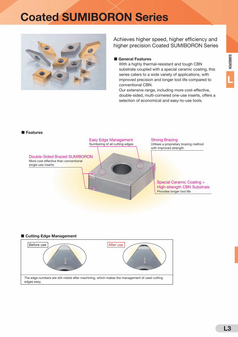
Coated SUMIBORON Series
General Features
Achieves higher speed, higher efficiency and
higher precision Coated SUMIBORON Series
Features
Cutting Edge Management
Special Ceramic Coating +
High-strength CBN SubstrateProvides longer tool life
Strong BrazingUtilises a proprietary brazing method
with improved strength
Double-Sided Brazed SUMIBORONMore cost effective than conventional
single-use inserts
Easy Edge ManagementNumbering of all cutting edges
With a highly thermal-resistant and tough CBN
substrate coupled with a special ceramic coating, this
series caters to a wide variety of applications, with
improved precision and longer tool life compared to
conventional CBN.
Our extensive range, including more cost-effective,
double-sided, multi-cornered one-use inserts, offers a
selection of economical and easy-to-use tools.
The edge numbers are still visible after machining, which makes the management of used cutting
edges easy.
Before use After use
L4
SUM
IBO
RON
L
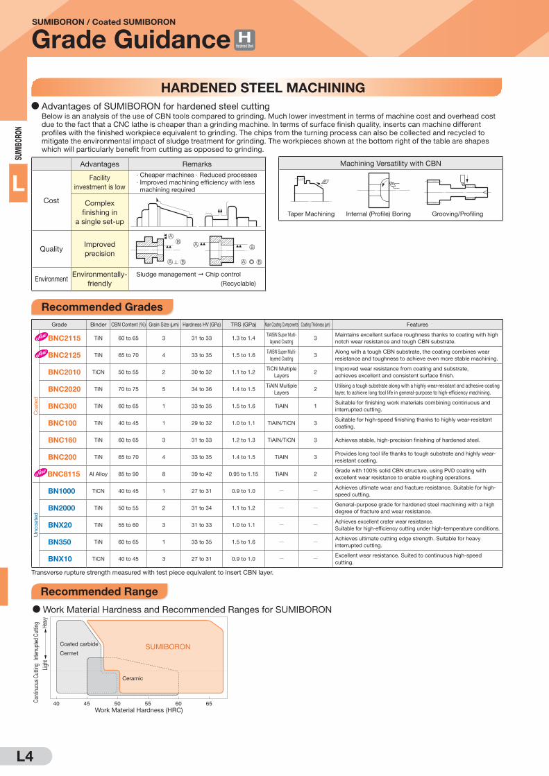
SUMIBORON / Coated SUMIBORON
Grade Guidance
Grade Binder CBN Content (%) Grain Size (μm) Hardness HV (GPa) TRS (GPa) Main Coating Components Coating Thickness (μm) Features
Co
ate
d
BNC2115 TiN 60 to 65 3 31 to 33 1.3 to 1.4TiAlSiN Super Multi-
layered Coating3
Maintains excellent surface roughness thanks to coating with high
notch wear resistance and tough CBN substrate.
BNC2125 TiN 65 to 70 4 33 to 35 1.5 to 1.6TiAlBN Super Multi-
layered Coating3
Along with a tough CBN substrate, the coating combines wear
resistance and toughness to achieve even more stable machining.
BNC2010 TiCN 50 to 55 2 30 to 32 1.1 to 1.2TiCN Multiple
Layers2
Improved wear resistance from coating and substrate,
achieves excellent and consistent surface finish.
BNC2020 TiN 70 to 75 5 34 to 36 1.4 to 1.5TiAlN Multiple
Layers2
Utilising a tough substrate along with a highly wear-resistant and adhesive coating
layer, to achieve long tool life in general-purpose to high-efficiency machining.
BNC300 TiN 60 to 65 1 33 to 35 1.5 to 1.6 TiAIN 1Suitable for finishing work materials combining continuous and
interrupted cutting.
BNC100 TiN 40 to 45 1 29 to 32 1.0 to 1.1 TiAIN/TiCN 3Suitable for high-speed finishing thanks to highly wear-resistant
coating.
BNC160 TiN 60 to 65 3 31 to 33 1.2 to 1.3 TiAIN/TiCN 3 Achieves stable, high-precision finishing of hardened steel.
BNC200 TiN 65 to 70 4 33 to 35 1.4 to 1.5 TiAIN 3Provides long tool life thanks to tough substrate and highly wear-
resistant coating.
BNC8115 Al Alloy 85 to 90 8 39 to 42 0.95 to 1.15 TiAlN 2Grade with 100% solid CBN structure, using PVD coating with
excellent wear resistance to enable roughing operations.
Unco
ate
d
BN1000 TiCN 40 to 45 1 27 to 31 0.9 to 1.0 Q QAchieves ultimate wear and fracture resistance. Suitable for high-
speed cutting.
BN2000 TiN 50 to 55 2 31 to 34 1.1 to 1.2 Q QGeneral-purpose grade for hardened steel machining with a high
degree of fracture and wear resistance.
BNX20 TiN 55 to 60 3 31 to 33 1.0 to 1.1 Q QAchieves excellent crater wear resistance.
Suitable for high-efficiency cutting under high-temperature conditions.
BN350 TiN 60 to 65 1 33 to 35 1.5 to 1.6 Q QAchieves ultimate cutting edge strength. Suitable for heavy
interrupted cutting.
BNX10 TiCN 40 to 45 3 27 to 31 0.9 to 1.0 Q QExcellent wear resistance. Suited to continuous high-speed
cutting.
Advantages Remarks
Cost
Facility
investment is low
· Cheaper machines · Reduced processes
· Improved machining efficiency with less
machining required
Complex
finishing in
a single set-up
QualityImproved
precision
EnvironmentEnvironmentally-
friendly
Sludge management Chip control
(Recyclable)
Machining Versatility with CBN
HARDENED STEEL MACHINING
FFFF
FF
FF
Internal (Profile) Boring Grooving/ProfilingTaper Machining
D Advantages of SUMIBORON for hardened steel cutting Below is an analysis of the use of CBN tools compared to grinding. Much lower investment in terms of machine cost and overhead cost
due to the fact that a CNC lathe is cheaper than a grinding machine. In terms of surface finish quality, inserts can machine different
profiles with the finished workpiece equivalent to grinding. The chips from the turning process can also be collected and recycled to
mitigate the environmental impact of sludge treatment for grinding. The workpieces shown at the bottom right of the table are shapes
which will particularly benefit from cutting as opposed to grinding.
Recommended Grades
Recommended Range
Hardened Steel
Transverse rupture strength measured with test piece equivalent to insert CBN layer.
D Work Material Hardness and Recommended Ranges for SUMIBORON
40 45 50 55 60 65Work Material Hardness (HRC)
Heav
yLig
ht
Interr
upte
d Cu
tting
Contin
uous
Cuttin
g
Coated carbide
CermetSUMIBORON
Ceramic

L5
SUM
IBORO
N
L
SUMIBORON
Grade Guidance
Applications
Application Range
Cut
ting
Spe
ed v
c (m
/min
)
300
200
100
50
(30)
Frequency of Interruption
Work Material
High LowMachine Rigidity
Light Interrupted Heavy InterruptedContinuous
Induction Hardened Steel
Carburised MaterialsBearing Steel
Die Steel
HSS
Uncoated SUMIBORON
Coated SUMIBORON
Coated SUMIBORON: 1st recommendation for hardened steel machining, excellent performance in high-speed,
high-efficiency machining.
Uncoated SUMIBORON: Optimal for machining small items with a limited cutting speed and hardened steel.
Series Applications
Coated
SUMIBORON
· First recommendation for hardened steel
machining
· Machining requiring high speed and high
accuracy
· Machining requiring high efficiency, such as
carburised layer removal
Uncoated
SUMIBORON
· Machining where cutting speed cannot be
increased, such as small product machining
· Machining of workpieces containing hard
particles such as mold components
· Machining with low tool rigidity
BNC2010 BNC2020
BNC2115 BNC2125
BNC300
Coated SUMIBOROND Induction Hardened Steel (S45C/S55C, etc.), Carburised Steel
Impact Force on Cutting Edge LargeSmall
300
200
100
Interrup
tion
Stren
gth
Cuttin
g Spe
ed V
C (m
/min)
Light Interrupted Heavy InterruptedContinuous
Uncoated SUMIBOROND Die Steel (SKD11/SKD61, etc.), HSS
Impact Force on Cutting Edge LargeSmall
150
100
50
Interrup
tion
Stren
gth
Cuttin
g Spe
ed V
C (m
/min)
Light Interrupted Heavy InterruptedContinuous
BN1000
BN2000
BN350
BN7000HSS Machining
D Induction Hardened Steel (S45C/S55C, etc.), Carburised SteelUncoated SUMIBORON
Impact Force on Cutting Edge LargeSmall
300
200
100
Interrup
tion
Stren
gth
Cutting
Spee
d V
C (m
/min)
Light Interrupted Heavy InterruptedContinuous
BNX20
BN1000
BN2000
BN350
Hardened Steel

L6
SUM
IBO
RON
L
SUMIBORON
Grade Guidance
50 100
D
D
D
BN2000BNC300BN350
Tool Grade Tool Life RatioTool
ø100
50 100
D
D
D
BN2000BNC300BN350
Tool Grade Tool Life RatioTool50 100
D
D
D
BN2000BNC300BN350
Tool Grade Tool Life RatioTool
Cutting Performance (Interrupted Cutting)
Work Material : SCM415H (58 to 62HRC)
Tool Cat. No. : DNGA150408
Cutting Conditions : f = 0.1mm/rev, ap = 0.2mm Wet
[Light Int. - Chamfered 4-Holed Face (Interrupted Cutting 25%)]
Work Material : SCr420H (58 to 62 HRC)
Tool Cat. No. : CNGA120408
Cutting Conditions : vc = 100m/min, f = 0.1mm/rev, ap = 0.2mm Dry
Work Material : SCr420H (58 to 62 HRC)
Tool Cat. No. : CNGA120408
Cutting Conditions : vc = 100m/min, f = 0.1mm/rev, ap = 0.2mm Dry
[Medium Int. - Chamfered 8-Holed Face (Interrupted Cutting 50%)]
[Heavy Int. - U-Grooved Face (Interrupted Cutting 100%)]
Work Material : SCr420H (58 to 62 HRC)
Tool Cat. No. : CNGA120408
Cutting Conditions : vc = 100m/min, f = 0.1mm/rev, ap = 0.2mm Dry
Work Material : SCr420H (58 to 62 HRC)
Tool Cat. No. : CNGA120408
Cutting Conditions : vc = 200m/min, f = 0.1mm/rev, ap = 0.2mm Dry
[High Speed Int. - Chamfered 8-Holed Face (Interrupted Cutting 50%)]
50 100
D
D
D
BN2000BNC300BN350
Tool Grade Tool Life RatioTool
Cutting Performance (Continuous Cutting)
Tool Life (min)
Tool Life Criterion: VBmax = 0.1mm
Cu
ttin
g S
pee
d v
C (m
/min
)
1
100
50
150
200
300
10 100 300200
BNC2115BNC2125BNC2010BNC2020BN2000Ceramic
Hardened Steel

L7
SUM
IBORO
N
L
SUMIBORON / Coated SUMIBORON
Grade Guidance
High-speed Machining High-speed Machining High-precision Machining
1,000
500
200
1 10 20
BNC8115/BNS8125BNS800BN7000BN500
D Gray Cast Iron
Tool Life Ratio
Ceramics
Coated carbide
Cermet
Cu
ttin
g S
pe
ed
vC
(m/m
in) 500
200
1 10Tool Life Ratio
Ceramics
Coated carbide
Cermet
D Ductile Cast Iron
BNX10
BNC500
BN7000
Cutting
Speed
vC
(m/m
in)
0.4 0.8 1.6 3.2
BNS8125BNS800BN7000BNC500
Surface Roughness Standard Ra (μm)Good
Ceramics
Coated carbide
Cermet
Go
od
D
ime
nsio
na
l To
lera
nc
e
Transverse rupture strength measured with test piece equivalent to insert CBN layer.
Refer to pages L9 to L11 for machining of sintered components, rolls, hard facing alloys, hardened stainless steel, titanium alloys, and heat-resistant alloys.
Grade Binder CBN Content (%) Grain Size (μm) Hardness HV (GPa) TRS (GPa) Main Coating Components Coating Thickness (μm) Features
Unco
ate
d
BNS8125 Al Alloy 85 to 90 8 39 to 42 0.95 to 1.15 Q QGrade with 100% solid CBN structure that exhibits excellent
wear and fracture resistance.
BNS800 Al Alloy 85 to 90 8 39 to 42 0.9 to 1.1 Q QGrade with solid CBN structure that has excellent thermal shock
resistance.
BN7000Co
Compound90 to 95 2 41 to 44 1.8 to 1.9 Q Q
Grade exhibiting wear and fracture resistance in cutting of cast
iron and exotic alloys.
BN500 TiC 65 to 70 6 32 to 34 1.0 to 1.1 Q QGrade optimised for cast iron cutting. Provides superior wear
and fracture resistance.
Co
ate
d BNC8115 Al Alloy 85 to 90 8 39 to 42 0.95 to 1.15 TiAlN 2Grade with 100% solid CBN structure, using PVD coating with
excellent wear resistance that enables roughing operations.
BNC500(For Ductile Cast Iron)
TiC 60 to 65 4 32 to 34 1.1 to 1.2 TiAIN 3Suitable for machining of hard-to-cut cast iron, thanks to the
highly wear-resistant substrate and coating.
100 200 300 350 500400
Ni-resistant
Cast Iron
High-Cr
Cast Iron
FCV
(CGI)
Work MaterialWork Material
StructureExamples
Cutting Speed vC (m/min)
Austenite
Austenite
Pearlite
Piston ring
Pump Part
Engine blocks
Cylinder heads
Brake discs
Hardness
(HB)
150 to 200
250 to 350
400 to 580
BNC500
BNS8125/BNS800
BNC500
D Special Cast Iron
500
0
200
300
400
2.01.5 2.51.00.5 3.0
Depth of Cut ap (mm)
Cu
ttin
g S
pe
ed
vC
(m/m
in)
D Gray Cast Iron D Ductile Cast Iron
BNC8115
BNS8125Cu
ttin
g S
peed
vC
(m/m
in)
2,000
2,500
0
500
1,000
1,500
4.0
Finishing region
Roughing region
1.0 2.0 3.0
Depth of Cut ap (mm)
BN7000BNS800
BNC8115BNS8125
BN500
BN7000 BNC500
D Advantages of machining cast iron with SUMIBORON
Compared with conventional tools, a longer tool life for high speed machining is realized, machining efficiency is improved and better wear
resistance, a sharper edge, excellent surface roughness and dimensional tolerance are achieved.
SUMIBORON is ideal for finishing of gray cast iron and special cast iron through FCD (ductile cast iron) and heat-treated high-grade cast
iron such as ADI.
Recommended Grades
Application Range
CAST IRON MACHINING
Cast Iron

L8
SUM
IBO
RON
L
SUMIBORON / Coated SUMIBORON
Grade Guidance
Cutting Oil: Dry cut
BN7000/BNC8115/BNS8125/BN500Gray Cast Iron Turning
Recommended Grade
0.1
0.2
0.3
0 20 40 60 80 100Cutting Distance (km)
D Continuous Cutting
Fla
nk W
ear
Wid
th (m
m)
BN500
Ceramic
D
0.06
0.04
0.02
0.08
0.10
0 20 40 60 80Cutting Distance (km)
D High Speed Continuous Cutting
Fla
nk W
ear
Wid
th (m
m)
BN7000
Conventional
CBN
D
DD
DD D D
D
Chipping
0
BNS8125Able to Continue
7
Competitor's
solid product
CBN
Cutting Distance (km)
D Interrupted Cutting
Fla
nk W
ear
Wid
th (m
m)
1 2 3 4 5 6
0.05
0.1
D
D
DD
BNC500 BNC8115/BNS8125/BN7000Ductile Cast Iron Turning Milling Gray Cast Iron
Recommended Grade Recommended Grade
D FCD450
Cu
ttin
g S
peed
vC
(m/m
in)
Fla
nk
We
ar
Wid
th (
mm
)
300200 400 5000 100
0.04
0.02
0.10
0.08
0.06
D Cast Iron Milling
Chip Evacuation Rate (cm3)Tool Life (km) Life Criterion VBmax. = 0.2mm
BNC500
BN7000BN500
D FCD700
Cu
ttin
g S
peed
vC
(m/m
in)
1,000
1000 1 10 100
1,000
1000.1 1 10 100
D
DD
DD
D
D
D
D D
DD
D
DD
DD
D
DDD
DBN7000 BNC500
BN500
DDD
D
DDD
DD
D
DDBN7000
Conventional CBN
Tool Life (km) Life Criterion VBmax. = 0.2mm
Work Material: FC300 (Pearlite)
Tool Cat. No.: 2NU-CNGA120408
Cutting Conditions: vc=800m/min, f =0.15mm/rev, ap = 0.2mm Wet
Work Material: FC300 (Pearlite)
Tool Cat. No.: SNGN090308
Cutting Conditions: vc=600m/min, f =0.3mm/rev, ap = 0.5mm Dry
Work Material: FC300 (Pearlite)
Tool Cat. No.: SNGN120412
Cutting Conditions: vc=500m/min, f =0.3mm/rev, ap = 0.15mm Wet
Work Material: FCD450 (Continuous Cutting)
Cutting Conditions: f = 0.2mm/rev, ap = 0.2mm Wet
Work Material: FCD700 (Continuous Cutting)
Cutting Conditions: f = 0.2mm/rev, ap = 0.2mm Wet
Work Material: FC250 (Pearlite)
Tool Cat. No.: FMU4100R SNEW1203ADTR
Cutting Conditions: vc = 1,500m/min, f = 0.2mm/rev, ap = 0.3mm Dry
Recommended Cutting Conditions
Cutting Performance
Cast Iron
100
BN7000
BNC8115 / BNS8125
BN7000
BNS8125 / BNS800
BNC500
BN7000
BNC500
BNC500
500 2,000
200 2,000
200 700
200 800
200
20080
1,000
1,000 2,000Cutting Speed vc (m/min) Feed Rate f
(mm/rev)Depth of Cut ap
(mm)
0.1 to 0.5FC200 to FC300
(HB ≤ 230)
FCD450 to FCD550
FCD600 to FCD700
Q
(HB ≥ 200)
≤ 1.0
0.1 to 0.4 ≤ 0.5
0.1 to 1.0 ≤ 4.0
0.1 to 0.5 ≤ 1.0
0.1 to 0.8 ≤ 2.0
0.1 to 0.4
0.1 to 0.4
≤ 0.5
≤ 0.6
0.1 to 0.4 ≤ 0.5
0.1 to 0.4 ≤ 0.4
200 400
Work Material Recommended Cutting ConditionsRecommended
GradeMaterial
Gray Cast Iron
Alloy Cast Iron
Ductile Cast Iron
Vermicular Cast IronFCV(CGI)
Standard (Hardness)
200 500
150 500
BN500
BNC8115
BNS812530080
0.1 to 0.5
0.1 to 0.5
≤ 3.0
≤ 3.0
20080
D Turning
D Milling
Cutting Oil: Wet cut (BNC8115/BNS8125/BNS800 can also be used dry)
100
BN7000
1,000 2,000Cutting Speed vc (m/min)
0.1 to 1.0 ≤ 4.0
Recommended Cutting ConditionsRecommended
GradeMaterial Standard (Hardness)
2,0008000.1 to 0.5
BNS8125 / BNS8002,000800
FC200 to FC300
(HB ≤ 200)
≤ 0.5
Gray Cast Iron
Feed Rate f(mm/rev)
Depth of Cut ap
(mm)
Work Material

L9
SUM
IBORO
N
L
SUMIBORON / Coated SUMIBORON
Grade Guidance
Sintered Components
SINTERED COMPONENT MACHINING
D General Sintered Alloy D High-Density/Sintered Alloy
300
200
100
0 0.1 0.2 0.3 0.4 0.5
0.30.20.15 0.250.10.05
Finishing region
Roughing region
General Sintered Alloy (50 to 90HRB)
Depth of Cut ap (mm)
Feed Rate f (mm/rev)
Cu
ttin
g S
peed
vc (
m/m
in)
BN7000BN7500BN7115
Sintered Alloy
300
200
100
0 0.1 0.2 0.3 0.4 0.5
Finishing region Roughing region
Depth of Cut ap (mm)
Feed Rate f (mm/rev)
High-Density/Sintered Alloy (30 to 65 HRC)
Cut
ting
Sp
eed
vc
(m/m
in)
0.30.20.15 0.250.10.05
BN7000BN7500BN7115
Sintered Alloy
Grade Binder CBN Content (%) Grain Size (μm) Hardness HV (GPa) TRS (GPa) Main Coating Components Coating Thickness (μm) Features
BN7115Co
Compound90 to 95 1 41 to 44 2.2 to 2.3 Q Q
Grade balancing ultimate cutting edge sharpness with
fracture resistance, suitable for finishing of sintered alloy.
BN7500Co
Compound90 to 95 1 41 to 44 2.0 to 2.1 Q Q
Grade maintaining good cutting edge
sharpness, suitable for finishing of sintered
alloy.
BN7000 Co
Compound90 to 95 2 41 to 44 1.8 to 1.9 Q Q
Grade exhibiting improved wear and
fracture resistance in roughing of sintered
materials.
D Advantages of cutting sintered components with SUMIBORON SUMIBORON has much smaller edge wear than cemented carbide or cermet. It also has better wear resistance and can form a sharp edge easily.
SUMIBORON is able to prevent burrs and chipping on the edges of the workpiece, achieving good machining precision and surface roughness.
Recommended Grades
Valve Seat Ring (VSR)
D Recommended Grade by Machining Application
D Grade Performance Comparison
*VSR has both (Intake: IN) and (Exhaust: EX) with the exhaust generally being hardened.
12
0 50 100
10
8
6
4
2
150 200Cutting Speed vC (m/min)
D D
D
DD
D
DD0.1
0 50 100
0.2
0.3
0.4
0.5
150 200Cutting Speed vC (m/min)
Fla
nk W
ear
Wid
th (m
m)
D D DD
DDDD
Cutting Speed vC (m/min)
0 50 100
0.7
0.6
0.5
0.4
0.3
0.2
0.1
150 200
Maxim
um
heig
ht
of
burr
(m
m)
DD
D
D
D DD D
Cemented
Carbide
Cermet
SUMIBORON
Cemented Carbide
Cermet
SUMIBORON
Cermet
Cemented Carbide
SUMIBORON
Surf
ace R
oug
hness R
z (μm
)
BN350
BN500
300HV HighLow 300HV HighLow
Gasoline VSR material Diesel VSR material
Plunge cut
Traverse cut
Work material hardness (HV)
BN7000BN7115BN7500
BN7000BN7115BN7500
BN7000BN7115BN7500
BN7000BN7115BN7500
BN500
BN350
Cutting Speed
vc (m/min)
Feed Rate
f (mm/rev)
Depth of Cut
ap (mm)
50 to 125 0.03 to 0.2 0.05 to 0.5
3,200 holes
800 holes
BN7000
Competitor's
CBN
With superior fracture resistance, the BN7000 can achieve
double our competitors' tool life
Work Material: Sintered Alloy F-08C2 equivalent
Machining Application: ø80-ø100 heavy interrupted facing with grooves and drilled holes (after 40 passes)
Tool Cat. No.: TNGA160404
Cutting Conditions: f = 0.1mm/rev, ap = 0.1mm Wet
Work Material : Sintered Alloy (150 to 250 HV)
Machining Application : VSR(IN) 45° Surface Finishing
Tool Cat. No. : TBGN060104B
Cutting Conditions : vc=100m/min, f =0.08mm/rev Wet
For general sintered alloy, cemented carbide and cermet grades can perform up to vc = 100m/min.
However, around vc = 120m/min, wear becomes rapid and surface roughness deteriorates with increased
burrs. On the other hand, SUMIBORON exhibits stability and superior wear resistance, burr prevention
and surface roughness, especially at high speeds.
Cutting Performance
Recommended Grades
Application Examples
Recommended Cutting Conditions
Transverse rupture strength measured with test piece equivalent to insert CBN layer.
Sintered Alloy
L10
SUM
IBO
RON
L
SUMIBORON / Coated SUMIBORON
Grade Guidance
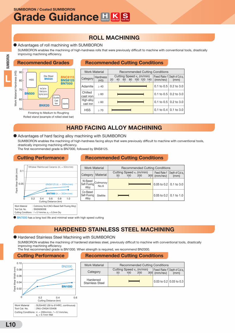
ROLL MACHINING
HARD FACING ALLOY MACHINING
HARDENED STAINLESS STEEL MACHINING
D Advantages of roll machining with SUMIBORON
SUMIBORON enables the machining of high-hardness rolls that were previously difficult to machine with conventional tools, drastically
improving machining efficiency.
90
BN500
BNC8115BNS8125BN7000
BNX20
80
70
60
50Finishing to Medium to Roughing
Rolled stand (example of rolled steel bar)
HSS
DuctileCastIron Adamite
Hard Cast Iron Chilled Cast Iron
High Alloy Cast Iron
Wor
k M
ater
ial H
ard
ness
(HS
)
BNX20Die Steel
20 40 60 80 100 120 140
≥ 40
≥ 60
≥ 60
≥ 70
Adamite
Chilled cast iron
HSS
High-alloy cast iron
Work Material Recommended Cutting ConditionsCutting Speed vc (m/min)
0.1 to 0.5
0.1 to 0.5
0.1 to 0.5
0.1 to 0.4
Feed Rate f(mm/rev)
0.2 to 3.0
0.2 to 3.0
0.2 to 3.0
0.1 to 3.0
Depth of Cut ap
(mm)Category Hardness(HS)
D Advantages of hard facing alloy machining with SUMIBORON
SUMIBORON enables the machining of high-hardness facing alloys that were previously difficult to machine with conventional tools,
drastically improving machining efficiency.
The first recommended grade is BN7000, followed by BNS8125.
0.20
0.05
0.1
0.4 0.6 0.8 1.0
Whisker Reinforced Ceramic (vc = 50m/min)
BN7000 (vc = 300m/min)
D BN7000 has a long tool life and minimal wear with high speed cutting
Fla
nk W
ear
Wid
th (m
m)
BNS8125 (vc = 300m/min)
Cutting Distance (km)
50 100 200 300Cutting Speed vc (m/min) Feed Rate f
(mm/rev)
0.05 to 0.2
0.05 to 0.2
Depth of Cut ap
(mm)
0.1 to 3.0
0.1 to 1.0
ColmonoyNo.6
Stellite
Ni-Based Self-Fluxing
Alloy
Co-Based Self-Fluxing
Alloy
Work Material Recommended Cutting Conditions
Category Material
Work Material : Colmonoy No.6 (NiCr-Based Self-Fluxing Alloy)
Tool Cat. No. : SNGN090308
Cutting Conditions : f = 0.1mm/rev, ap = 0.2mm Dry
Work Material : SUS440C (59 to 61HRC, continuous)
Tool Cat. No. : 2NU-CNGA120408
Cutting Conditions : vc = 200m/min, f = 0.1mm/rev, ap = 0.1mm Wet
D Hardened Stainless Steel Machining with SUMIBORON
SUMIBORON enables the machining of hardened stainless steel, previously difficult to machine with conventional tools, drastically
improving machining efficiency.
The first recommended grade is BN1000. When strength is required, we recommend BN2000.
Cutting Distance (km)
Fla
nk W
ear
Wid
th (m
m)
0.02
0.04
0.06
0.08
0.10
0 0.2 0.4 0.6
BN2000
BN1000
Cutting Speed vc (m/min) Feed Rate f(mm/rev)
0.03 to 0.2
Depth of Cut ap
(mm)
0.03 to 0.3Hardened Stainless Steel
Work Material Recommended Cutting Conditions
Category 50 100 200 300
Recommended Grades Recommended Cutting Conditions
Cutting Performance Recommended Cutting Conditions
Cutting Performance Recommended Cutting Conditions
Cast IronHardened Steel Exotic Alloy

L11
SUM
IBORO
N
L
SUMIBORON / Coated SUMIBORON
Grade Guidance
HEAT-RESISTANT ALLOY MACHINING
TITANIUM ALLOY CUTTING
SUMIBORON is best suited for finishing of heat resistant steel
D Advantages of titanium alloy machining with SUMIBORON
SUMIBORON enables high speed machining of titanium alloys that were previously difficult to machine with conventional tools, drastically
improving machining efficiency.
Work Material : Titanium Alloy (Ti-6Al-4V)
Tool Cat. No. : CNGA120408
Cutting Conditions : vc = 150m/min, f = 0.15mm/rev, ap = 0.5mm
Wet (High Pressure Coolant)
D Advantages of heat-resistant alloy machining with SUMIBORON
SUMIBORON provides long tool life in the finishing of heat-resistant alloys.
Feed Rate f (mm/rev)
Cu
ttin
g S
pe
ed
vC
(m/m
in)
50
30
0.1
100
200
400
0.2 0.3 0.4
Cemented Carbide (Roughing, Med. Finishing)
BN350
BN7000
50 100 150 200Cutting Speed vc (m/min) Feed Rate f
(mm/rev)
0.05 to 0.2
0.05 to 0.2
Depth of Cut ap
(mm)
0.1 to 1.0
0.1 to 1.0
Inconel718
Stellite
Ni-based Heat-resistant
Alloy
Co-Based Heat-Resistant
Alloy
Work Material Recommended Cutting Conditions
Category Material
Recommended Grades
Grade Binder CBN Content (%) Grain Size (μm) Hardness HV (GPa) TRS (GPa) Main Coating Components Coating Thickness (μm) Features
NCB100 Q 100 up to 0.5 51 to 54 1.8 to 1.9 Q QIdeal for high-efficiency finishing of
titanium alloy.
Cutting Performance Recommended Cutting Conditions
Flan
k W
ear
Wid
th (m
m)
0
0.1
0.2
0.3
0.4
10 20 30 40
Cutting Distance (km)
F
F
FF
DDDDD
D DD D
DD
DD
DNCB100
Conventional PCDConventional CBN
Carbide
50 100 150 200 250 300
30 - 35
32 - 38
32 - 38
Ti-6Al-4V
Ti-5Al-5V-5Mo-3Cr
Ti-10V-2Fe-3Al
Work MaterialGrade
Recommended Cutting ConditionsCutting Speed vc (m/min) Feed Rate f
(mm/rev)Depth of Cut ap
(mm)Composition Hardness(HRC)
0.05
0.05
0.05
-
-
-
-
-
-
0.20
0.20
0.20
0.15
0.10
0.10
0.10
0.10
0.10
-
-
-
-
-
-
0.50
0.50
0.50
0.30
0.30
0.30
NCB100
NCB100
NCB100
Min. - Optimum - Max.
Recommended Grades Recommended Cutting Conditions
Exotic Alloy
Transverse rupture strength measured with test piece equivalent to insert CBN layer.

L12
SUM
IBO
RON
L
Coated SUMIBORON for Hardened Steel Machining
BNC2115/BNC2125/BNC2010/BNC2020 Hardened Steel
The Pinnacle of High Accuracy/High-efficiency Cutting
General Features
BNC2115/BNC2125 have been added to our coated
SUMIBORON series and are our first recommendations
for hardened steel machining, for even higher efficiency
machining.
In combination with BNC2010/BNC2020, which
emphasize stable tool life, they improve productivity in all
kinds of hardened steel machining.
Features
D BNC2115
D BNC2125
D BNC2010
D BNC2020
Application Range
Differentiation
BNC2010 BNC2020
BNC2115 BNC2125
BNC300BNC300
Impact Force on Cutting Edge LargeSmall
300
200
100
Inte
rru
ptio
n
Str
en
gth
Cu
ttin
g S
pe
ed
vC
(m/m
in)
Light Interrupted Heavy InterruptedContinuous
BNC2010BNC2020 BNC2125
Machine Rigidity
Uncoated
SUMIBORON
Wo
rk
Mate
rial
Coated SUMIBORON
Induction Hardened/Carburised Steel
HSS/Die Steel Bearing steel
High
Cu
ttin
g S
peed
H
igh
BNC2115
· The definitive grade in high-accuracy machining
Realises long tool life with excellent surface roughness and stable machining.
· Further maintains excellent surface roughness
Maintains excellent surface roughness thanks to a coating with high notch wear resistance and tough
CBN substrate.
· First recommendation for hardened steel machining
Superb wear and fracture resistance.
· Along with a tough CBN substrate, the coating combines wear resistance and
toughness to realise stabler machining
Achieves long, stable tool life even in high-efficiency and interrupted machining.
· Grade for high-precision finishing requiring good surface roughness and finished surface accuracy
Grade ideal for high-precision machining, with highly wear-resistant CBN substrate and coating.
· General-purpose grade suitable for typical hardened steel machining applications
Achieves further stability in machining of a wide range of hardened steel components.

L13
SUM
IBORO
N
L
High-precision Machining (Medium- to High-speed) General Machining (Medium- to High-speed)
High-precision Machining (Low- to Medium-speed) General-purpose Machining (Low- to Medium-speed, Unstable Cutting)
TiAlBN Super Multi-layered Coating
Coloured Layer (Gold) Coloured Layer (Silver)
Highly Adhesive Layer
TiAlSiNSuper Multi-Layered Coating
TiCN Layer
TiAlSiNSuper Multi-Layered Coating
TiAlSiNSuper Multi-Layered Coating
Highly Adhesive Layer
CBN Substrate and Coating Structure
Tough CBN
Substrate
Improved Adhesion Strength Improved Adhesion Strength
Crater Wear
Suppressed
Tough CBN
Substrate
BNC2010 BNC2020
Coloured Layer (Gold)
AlCrN Multilayer Coating
AlCrN Multilayer Coating
TiCN Layer
TiCN Layer
TiCN Layer
AlCrN Multilayer Coating
Coloured Layer (Gold)
TiAlN Layer
Highly Adhesive Layer
Improved Wear Resistance
High Wear Resistance
CBN Substrate
Reduced Notch Wear
Tough CBN
Substrate
Improved Adhesion Strength
Improved Wear Resistance
TiCN Layer
BNC2115 BNC2125
Chipping Resistance Improved
Improved Wear Resistance
Coating Thickness: 3μm Coating Thickness: 3μm
Coating Thickness: 2μm Coating Thickness: 2μm
Reduced Notch
Wear Maintained
Surface Roughness
Thick layer of laminated high-strength TiAlSiN super multi-layered coating and highly heat-resistant TiCN coating. Achieves excellent surface finish quality with application to a tough substrate
Thick layer of super-multilayered ultra-fine TiAlBN coating, with high strength and high hardness High performance in a wide range of cutting through application to a tough substrate
Laminated high-strength AlCrN multi-layered coating and highly heat-resistant TiCN coating is applied to a highly wear-resistant substrate to maintain excellent surface finish quality
Application of highly wear-resistant TiAlN coating to a tough substrate Machining stability in low-rigidity environments and high-load cutting is dramatically improved
Coated SUMIBORON for Hardened Steel Machining
BNC2115/BNC2125/BNC2010/BNC2020 Hardened Steel
Recommended Cutting Conditions
GradeCutting Speed vc (m/min)
Min. - Optimum - Max.
Feed Rate fz (mm/t)
Min. - Optimum - Max.
Depth of Cut ap (mm)
Min. - Optimum - Max.
BNC2115 110- 180 -300 0.03- 0.10 -0.20 0.03-0.20-0.35
BNC2125 110- 160 -300 0.05- 0.20 -0.40 0.05-0.30-0.50
BNC2010 50- 140 -180 0.03- 0.10 -0.20 0.03-0.20-0.35
BNC2020 50- 120 -180 0.03- 0.20 -0.40 0.05-0.30-0.50
BNC300 50- 100 -150 0.03- 0.10 -0.20 0.03-0.20-0.30

L14
SUM
IBO
RON
L
Coated SUMIBORON for Hardened Steel Machining
BNC2115/BNC2125/BNC2010/BNC2020 Hardened Steel
Work Material : SCM415H (58 to 62HRC)
Tool Cat. No. : 4NC-DNGA150408
Cutting Conditions : vc = 200m/min, f = 0.1mm/rev, ap = 0.15mm Wet
Work Material : SUJ2 (58 to 62HRC)
Tool Cat. No. : 4NC-DNGA150408
Cutting Conditions : vc = 150m/min, f = 0.1mm/rev, ap = 0.2mm Wet
Work Material : SUJ2 (58 to 62HRC)
Tool Cat. No. : 4NC-DNGA150408
Cutting Conditions : vc = 150m/min, f = 0.15mm/rev, ap = 0.5mm, 63m/times, Wet
Work Material : SCM415H (58 to 62HRC)
Tool Cat. No. : 4NC-DNGA150408
Cutting Conditions : vc = 200m/min, f = 0.1mm/rev, ap = 0.15mm Wet
D BNC2115 D BNC2125
After Cutting 6km
After Cutting 6km
After Cutting 6km
Cutting Performance
Work Material : SCM415H (58 to 62HRC)
Tool Cat. No. : 4NC-DNGA150408
Cutting Conditions : vc = 120m/min, f = 0.14mm/rev, ap = 0.15mm Wet
Work Material : SCM415H with 5 grooves (58 to 62HRC)
Tool Cat. No. : 4NC-CNGA120412
Cutting Conditions : vc = 130m/min, f = 0.1mm/rev, ap = 0.6mm Dry
D BNC2020D BNC2010
Cutting Distance (km)
BNC2020
Conventional Coated CBN
Competitor's Coated CBN C
5.0Tool Life (km)
0 2.5
After Cutting 2.5km
After Cutting 3km
After Cutting 5km
0.01
0.02
0.03
0.04
0.05
0.06
0.07
20 4 6 8Cutting Distance (km)
Flan
k W
ear
Wid
th (m
m)
Competitor's Coated CBN A
Conventional Coated CBN
BNC2115Flank Wear Suppressed
Cutting Distance (km)
1.0
2.0
3.0
4.0
5.0
20 4 6 8 10
0.04
0.08
0.12
0.16
0.20
0 2 4 6Cutting Distance (km)
0
2.0
4.0
6.0
8.0
2 4 6 8
8
BNC2010
Competitor's Coated CBN B
Conventional Coated CBN
Conventional Coated CBN
Competitor's Coated CBN A
BNC2115
Flan
k W
ear
Wid
th (m
m)
After Cutting 6km
After Cutting 6km
Conventional Coated CBNFlank Wear Progresses
BNC2125Flank Wear Suppressed
Conventional Coated CBN
BNC2125
Conventional Coated CBN
No. of Passes until Tool Breakage
0 200 400 600 800 1,000 1,200 1,400
Stable Tool Life
BNC2125
Conventional Coated CBN
Competitor's Coated CBN A
BNC2115
BNC2010Reduces notch wear
Competitor's Coated CBN B Notch Wear Generated
After Cutting 6km
After Cutting 6km
Sur
face
Fin
ish
Rz
(μm
)S
urfa
ce F
inis
h R
z (μ
m)

L15
SUM
IBORO
N
L
Coated SUMIBORON/SUMIBORON for Hardened Steel Machining
BNC300/BN350
General Features
BNC300
A CBN substrate that emphasizes toughness is
coupled with a highly wear-resistant TiAlN-based
coating layer that has improved adhesion strength.
With a good balance of fracture and wear resistance,
this grade achieves a long, stable tool life in
interrupted cutting or in a mixture of continuous and
interrupted cutting.
BN350
SUMIBORON series' highest fracture resistance and
toughest CBN. Reliable grade for achieving stable tool
life in heavy interrupted cutting conditions. Features
D BNC300
D BN350
· Long, stable tool life in interrupted cutting Achieving long, stable tool life in heavy interrupted cutting, with superior fracture resistance.
· Superior dimensional tolerance TiAlN-based high-wear-resistance coating achieves superior dimensional tolerance even in interrupted
cutting.
· Supports various work material shapes Achieves long, stable tool life even in workpieces requiring both continuous and interrupted cutting.
· Superb stability with regard to fracture Superior fracture resistance, preventing the fractures that commonly occur during interrupted cutting.
Achieves a long, stable tool life.
Cutting Performance
Application Range Recommended Cutting
Conditions
(BNC300/BN350 common)
50 80 120100 150Cutting Speed vc (m/min)
Feed Rate f(mm/rev)
Depth of Cut ap
(mm)
0.03 to 0.20 0.03 to 0.30
Coolant: Dry
Heavy Interrupted Cutting: (Interrupted Cutting 100%)
2 3Cutting Distance (km)
Flan
k W
ear
Width
(mm)
0 1
0.05
0.10 BNC300: FractureCompetitor's CBN: Fracture
BN350Able to ContinueD
DD
DD D
D
Work Material : SCr420 (58 to 62 HRC)
Tool Cat. No. : 2NU-CNGA120408
Cutting Conditions : vc = 100m/min, f = 0.1mm/rev, ap = 0.2mm Dry
D BN350 exhibits very good fracture resistance.
Continuous + Mid Interrupted Cutting (Interrupted Cutting 50%)
2 3 4Cutting Distance (km)
Flan
k W
ear
Width
(mm)
0 1
0.05
0.10BN350
Coating chip-off
Competitor's Coated CBN: Fracture
FD
DD
D
DD D
D
Work Material : SCr420 (58 to 62 HRC)
Tool Cat. No. : 4NC-CNGA120408
Cutting Conditions : vc = 120m/min, f = 0.1mm/rev, ap = 0.2mm Dry
BNC300Able to Continue
D BNC300 has a superior balance of fracture and wear
resistance.
DCoated SUMIBORON DSUMIBORON
BNC2010 BNC2020
BNC2115 BNC2125
BNC300
BNX20
BN1000
BN2000
BN350
Impact Force on Cutting Edge LargeSmall
300
Inte
rrup
tio
n
Str
eng
th
Cu
ttin
g S
pe
ed
vC
(m
/min
)
Light Interrupted Heavy InterruptedContinuous
100
200
Impact Force on Cutting Edge LargeSmallInte
rrup
tio
n
Str
eng
th
Cu
ttin
g S
pe
ed
vC
(m
/min
)
Light Interrupted Heavy InterruptedContinuous
100
200
300
The Ultimate in Interrupted Cutting of Hardened Steel
BNC300
BN350
Hardened Steel

L16
SUM
IBO
RON
L
Uncoated SUMIBORON for Hardened Steel Machining
BN1000/BN2000
General Features
Uncoated SUMIBORON grades that have a newly
developed high-purity ceramic binder applied to them.
Both fracture and wear resistance are combined to
achieve a stable tool life in a wide variety of hardened steel
machining.
We offer a wide selection of tools starting with single-
cornered types.
Features
D BN1000 · SUMIBORON grade for high-speed machining with the best wear resistance
Providing superior tool life in continuous cutting to light interrupted cutting.
· Improved fracture resistance while also emphasizing wear resistance
Hardness and thermal resistance from the high-purity TiCN ceramic binder.
Sharpness Comparison
BN2000 Conventional Grade
Newly Developed High-purity Ceramic Binder
Application Range Recommended Cutting Conditions
Cutting Speed vc (m/min)
Feed Rate f(mm/rev)
Depth of Cut ap
(mm)
0.03 to 0.15 0.03 to 0.2
30 100120 150 200 250 300
BNX20
BN1000
BN2000
BN350
Impact Force on Cutting Edge LargeSmallInterruption
Strength
Cutting
Speed
vC
(m/m
in)
Light Interrupted Heavy InterruptedContinuous
100
200
300D BN1000
Cutting Speed vc (m/min)
Depth of Cut ap
(mm)
0.03 to 0.2 0.03 to 0.3
Feed Rate f(mm/rev)
30 80 120100 150 200 250 300
D BN2000
With a newly developed high-purity ceramic
binder, BN1000/BN2000 achieve toughness
and improved thermal resistance by decreasing
impurities to an extreme.
CBN
High-purity ceramic binder
BN1000/BN2000Conventional Grade
The impurities contained in the ceramic binder for conventional
grades decrease the sintered body strength and thermal resistance,
leading to cracks (breakage) and wear.
Ceramic Binder
CBN
Impurities
Cracks
Increased
Wear/
Reduced
Sharpness
D BN2000 · General-purpose grade suitable for typical hardened steel machining applications.
Provides stable tool life in everything from continuous cutting to light to medium interrupted cutting.
· Has a high degree of both fracture and wear resistance
Significant improvements in the performance of both by employing a high-purity ceramic binder.
· Stable surface roughness achieved by increasing edge sharpness (right figure)
Cutting Oil: Continuous Cutting Dry, Wet
Interrupted Cutting Dry
Small cutting edge roundness
compared to conventional grades
BN2000
BN1000
Hardened Steel

L17
SUM
IBORO
N
L
Uncoated SUMIBORON for Hardened Steel Machining
BN1000/BN2000
Cutting Performance
D BN1000 D BN1000/BN2000
D BN2000
D BN1000 D BN2000
Machining Precision
0 1 2 3Cutting Distance (km)
Fla
nk
We
ar
Wid
th (
mm
)
Work Material : SUJ2 (58 to 62HRC)
Tool Cat. No. : 2NU-CNGA120408
Cutting Conditions : vc = 150m/min, f = 0.1mm/rev, ap = 0.2mm Dry
Competitor's CBN A
BN1000
Wear Resistance (Continuous Cutting)
0.16
0.14
0.12
0.08
0.10
0.04
0.02
0.06 Conventional CBN (1)
Competitor's CBN (1)
Work Material : SCM415H with 8 grooves (58 to 62HRC)
Tool Cat. No. : 2NU-CNGA120408
Cutting Conditions : vc = 150m/min, f = 0.1mm/rev, ap = 0.2mm Dry
Tool Life Comparison (BN2000s previous CBN as 100%)
BN1000
Greatly improved fracture resistance while also emphasizing wear resistance.
Excellent fracture resistance compared with conventional tools
Approx. 2 times that of conventional tools
Chipping Resistance (Interrupted Cutting)
0 50 100 150
Conventional CBN (2)
Competitor's CBN (2)
Approx. 1.4 times that of conventional toolsBN2000
0 2 4 6 8 10Cutting Distance (km)
Fla
nk
We
ar
Wid
th (
mm
)
Work Material : SCM415H (58 to 62HRC)
Tool Cat. No. : 2NU-CNGA120408
Cutting Conditions : vc = 100m/min, f = 0.1mm/rev, ap = 0.2mm Dry
Conventional CBN
BN2000
Wear Resistance (Continuous Cutting)
0.25
0.20
0.15
0.10
0.05
Breakage -
Cannot Continue
Able to Continue
0 0.5 1.0 1.5 2.0 2.5 3.0 4.03.5
Dimensional Tolerance Comparison (Continuous Cutting)
4
2
6
8
10
Work Material : SCM415H ø130 O.D. (58 to 62 HRC)
Tool Cat. No. : 2NU-CNGA120408
Cutting Conditions : vc = 200m/min, f = 0.1mm/rev, ap = 0.1mm Wet
Cutting Distance (km)
Competitor's CBN B
BN1000
Wo
rk D
iam
ete
r V
ari
an
ce
(μ
m)
0 1 2 3 4 5 6 7
Conventional CBN
Competitor's CBN C
BN2000
Surface Roughness Comparison (Continuous Cutting)
1
2
3
4
Work Material : SCM415H (58 to 62HRC)
Tool Cat. No. : 2NU-CNGA120408
Cutting Conditions : vc = 100m/min, f = 0.08mm/rev, ap = 0.2mm Dry
Cutting Distance (km)
Su
rfa
ce
Fin
ish
Rz (
μm
)
Hardened Steel

L18
SUM
IBO
RON
L
SUMIBORON for Cast Iron/Sintered Alloy Machining / SUMIBORON for Sintered Alloy Machining
BN7000 Cast Iron Sintered Alloy /BN7115 Sintered
Alloy
General Features
Good wear resistance through high CBN content
also delivers superior fracture resistance by increasing the
binding strength between CBN particles.
Provides stable performance for high-speed finishing work
with cast iron, sintered alloys and exotic alloys.
Features
Application Range Recommended Cutting Conditions
D BN7000
Achieves high-efficiency machining of sintered alloys of various shapes with a standard + 2 types of
cutting edge variations. Also exhibits high performance for difficult-to-cut materials such as rolls, high
speed steel and heat-resistive alloys. Exhibits good thermal crack resistance in high-speed machining of
cast iron.
D BN7115
With improved CBN particle/binder boundary strength due to the special binder and improved binding
strength between CBN particles thanks to our proprietary sintering process, the edge sharpness in
sintered alloy machining is excellent and burrs and tearing are suppressed.
BN7115 Conventional Tool
Removal of Binder Comparison of CBN Particles' Binding Strength
High Edge Sharpness Cutting Edge Dulled
Conventional Tool
Removal of Binder Comparison of CBN Particles' Binding Strength
High Edge Sharpness Cutting Edge Dulled
BN7115BN7000
General Sintered Alloy
Work Material GradeRecommended Cutting Conditions
Cutting speed vc
(m/min)Feed Rate f
(mm/rev)Depth of Cut ap
(mm)
Cutting speed vc
(m/min)Feed Rate f
(mm/rev)Depth of Cut ap
(mm)
0.010.010.010.01
----
----
0.150.300.120.30
0.080.150.060.15
10101010
----
----
300300200200
150150100100
0.050.050.050.05
----
----
0.250.500.200.50
0.130.250.100.25
BN7115BN7000BN7115BN7000
Min. - Optimum - Max.
D Sintered Alloy
Cast Iron
Work Material GradeRecommended Cutting Conditions
0.05- -0.600.30100- -2,5001,000 0.05- -1.000.50BN7000
Min. - Optimum - Max.
D Cast Iron
Cut
ting
Edg
e S
harp
ness
G
ood
Frequency of Interruption Heavy
Breakage Control Emphasised
Good Surface Roughness
Burr Control EmphasisedLF Type
No R Honing LE Type
R Honing
LS Type
R Honing
HS Type
R Honing
StandardNo R Honing
US Type
R HoningMac
hine
d su
rfac
e qu
ality
G
ood
Frequency of Interruption Heavy
LF Type
Sharper edge
Strong Edge
StandardNo R Honing
HS Type
Poor surface roughness
Chipping
For higher dimensional tolerance with minimal burr
Rake FaceNegative land
width W
Flank
CBN
Honing
RNegative land angle R
StandardLFHS
15°
25°
0.12
0.12
NoNoYes
Sharp Edge
Type E W(mm) Honing
No R Honing
R Honing
StandardLFLELSHSUS
15°
15°25°25°
0.12
0.070.050.12
NoNoYesYesYesYes
Sharp EdgeSharp Edge
Type E W(mm) Honing
Rake FaceNegative land
width W
Flank
CBN
Honing
RNegative land angle R
High-density Sintered Alloy
D Sintered Alloy
(Mac
hine
d su
rfac
e qu
ality
G
ood)
Bur
rs
Tear
ing
Depth of Cut ap (mm)
Feed Rate f (mm/rev)
Cut
ting
Spe
ed v
c (m
/min
)
BN7000
300
200
100
0 0.1 0.2 0.3 0.4 0.5
0.30.20.15 0.250.10.05
Finishing region
Roughingregion
BN7000BN7115
Recommended Cutting Edge Treatment
K
Sintered Alloy
L19
SUM
IBORO
N
L
0 10 20155 25 30
Cutting Distance (km)
Fla
nk
Wea
r W
idth
(mm
)
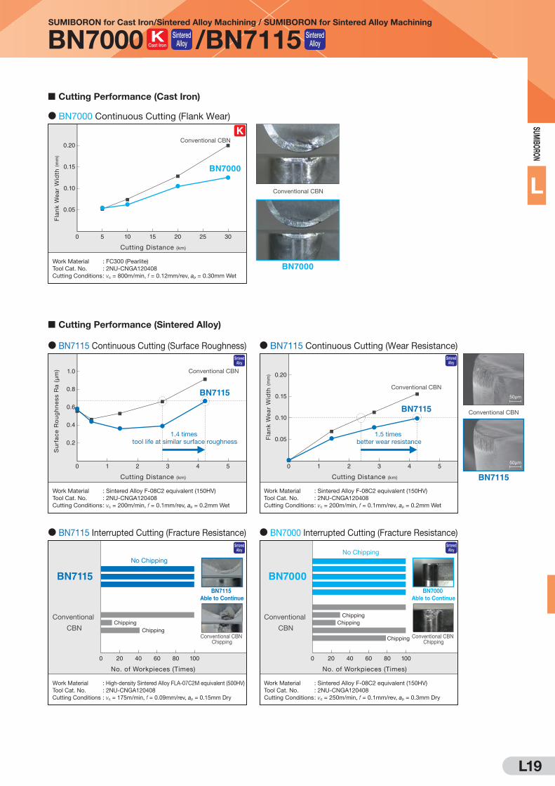
Work Material : FC300 (Pearlite)Tool Cat. No. : 2NU-CNGA120408Cutting Conditions : vc = 800m/min, f = 0.12mm/rev, ap = 0.30mm Wet
0.20
0.15
0.10
0.05 D D
DD
BN7000
BN7115
BN7115
Conventional CBN
Conventional CBN
Conventional CBN
BN7000
Conventional CBN
0 2 431 5
Cutting Distance (km)
Work Material : Sintered Alloy F-08C2 equivalent (150HV)Tool Cat. No. : 2NU-CNGA120408Cutting Conditions : vc = 200m/min, f = 0.1mm/rev, ap = 0.2mm Wet
1.0
0.8
0.6
0.4
0.2
0 2 431 5
Cutting Distance (km)
Fla
nk
Wea
r W
idth
(mm
)
Work Material : Sintered Alloy F-08C2 equivalent (150HV)Tool Cat. No. : 2NU-CNGA120408Cutting Conditions : vc = 200m/min, f = 0.1mm/rev, ap = 0.2mm Wet
0.20
0.15
0.10
0.05
Conventional
CBN
Work Material : Sintered Alloy F-08C2 equivalent (150HV)Tool Cat. No. : 2NU-CNGA120408Cutting Conditions : vc = 250m/min, f = 0.1mm/rev, ap = 0.3mm Dry
No. of Workpieces (Times)
0 100
ChippingChipping
Chipping
BN7000
D
DD D
D
D
D
D
D
50μm
Conventional CBN
50μm
BN7115
D BN7115 Continuous Cutting (Surface Roughness) D BN7115 Continuous Cutting (Wear Resistance)
D BN7000 Interrupted Cutting (Fracture Resistance)
BN7000
Able to Continue
Conventional CBN Chipping
No Chipping
Conventional
CBN
Work Material : High-density Sintered Alloy FLA-07C2M equivalent (500HV)Tool Cat. No. : 2NU-CNGA120408Cutting Conditions : vc = 175m/min, f = 0.09mm/rev, ap = 0.15mm Dry
No. of Workpieces (Times)
0 20 40 60 80 20 40 60 80100
ChippingChipping
BN7115
D BN7115 Interrupted Cutting (Fracture Resistance)
BN7115
Able to Continue
Conventional CBN Chipping
No Chipping
D BN7000 Continuous Cutting (Flank Wear)
1.4 times tool life at similar surface roughness
1.5 times better wear resistance
Su
rfac
e R
ou
gh
nes
s R
a (μ
m)
Cutting Performance (Cast Iron)
Cutting Performance (Sintered Alloy)
SUMIBORON for Cast Iron/Sintered Alloy Machining / SUMIBORON for Sintered Alloy Machining
BN7000 Cast Iron Sintered Alloy /BN7115 Sintered
Alloy
K
Sintered Alloy
Sintered Alloy
Sintered Alloy
Sintered Alloy

L20
SUM
IBO
RON
L
Coated Solid SUMIBORON/Solid SUMIBORON for Cast Iron and Hardened Steel Machining
BNC8115/BNS8125 Cast Iron Hardened Steel
General Features
Enables a wide range of machining from roughing to finishing
of cast iron, exotic alloy cast iron, and hardened steel.
100% solid CBN structure enables depth-of-cut of 0.5mm
and above.
Features D BNC8115
PVD coating with excellent wear resistance suppresses flank wear when machining difficult-to-cut cast
iron and hardened steel. Ideal for roughing and depth-of-cut of 0.5 to 3.0mm. Can also be used for
roughing and finishing of gray cast iron. Gold coating improves visibility of used corners.
D BNS8125
Optimising the particle size distribution of the CBN particles has resulted in improved chipping resistance
and longer life while maintaining wear resistance during gray cast iron machining.
h hi i diffi
Gray Cast Iron
Ductile Cast Iron
Gray Cast Iron
Work Material Grade
Recommended Cutting Conditions
Cutting Speed vc
(m/min)Feed Rate f
(mm/rev)Depth of Cut ap
(mm)
0.100.100.100.10
-
-
-
-
-
-
-
-
1.001.000.500.50
0.500.500.300.30
2002008080
-
-
-
-
-
-
-
-
2,000
2,000
300
200
1,000
1,000
160
120
≤ 4.0
≤ 4.0
≤ 3.0
≤ 3.0
BNC8115BNS8125BNC8115BNS8125
Min. - Optimum - Max.
D Cast Iron (Turning)
Hardened Steel
Work Material Grade
Recommended Cutting Conditions
Cutting Speed vc
(m/min)Feed Rate f
(mm/rev)Depth of Cut ap
(mm)
0.10- -0.400.2550 - - 150100 ≤ 3.0BNC8115
Min. - Optimum - Max.
D Hardened Steel (Turning)
Work Material Grade
Recommended Cutting Conditions
Cutting Speed vc
(m/min)Feed Rate f
(mm/rev)Depth of Cut ap
(mm)
0.100.10
-
-
-
-
1.001.00
0.500.50
800800
-
-
-
-
2,000
2,000
1,400
1,400
≤ 4.0
≤ 4.0
BNC8115BNS8125
Min. - Optimum - Max.
D Cast Iron (Milling)
Application Range
Recommended Cutting Conditions
Wet machining is recommended for gray cast iron For dry machining, BNC8115/BNS8125 are recommended for both roughing and finishing
D Gray Cast Iron D Ductile Cast Iron
D Hardened Steel
Cu
ttin
g S
peed
vc (m
/min
) 300
0
50
100
150
200
250
3.01.0 1.5 2.52.00.5
Depth of Cut ap (mm)
BNC2115BNC2125BNC2010BNC2020BNC300
Cu
ttin
g S
peed
vc (m
/min
)
Cu
ttin
g S
peed
vc (m
/min
)
2,000
2,500
0
500
1,000
1,500
4.0
Finishing region
Roughing region
1.0 2.0 3.0
Depth of Cut ap (mm) Depth of Cut ap (mm)
BNS800BN500
BN7000
BNC8115
BNS8125
BNC8115
500
0
200
300
400
2.01.5 2.51.00.5 3.0
BN7000
BNC500
BNC8115
BNS8125
K
K
H

L21
SUM
IBORO
N
L
Coated Solid SUMIBORON/Solid SUMIBORON for Cast Iron and Hardened Steel Machining
BNC8115/BNS8125 Cast Iron Hardened Steel
D Wear Resistance (Ductile Cast Iron Machining)
Work Material : FCD450
Tool Cat. No. : SNGN090308
Cutting Conditions : vc = 300m/min, f = 0.2mm/rev, ap = 0.2mm Wet
Work Material : FCD450
Tool Cat. No. : SNGN090308
Cutting Conditions : vc = 300m/min, f = 0.2mm/rev, ap = 0.2mm Wet
BNC8115(After Cutting 2.5km)
Conventional Tool (Uncoated)
(After Cutting 2.5km)
Cutting Distance (km) Cutting Distance (km)
Fla
nk W
ear
Wid
th (
mm
)
BNC8115
Conventional CBN
0
0.04
0.08
0.16
0.20
0.12
0.5
Fla
nk W
ear
Wid
th (
mm
)
0
0.4
0.3
0.2
0.1
0.5 1.0 1.5 2.0 2.51.0 1.5 2.0 2.5D
D DD D
D D
D Wear Resistance (Hardened Steel Machining)
Work Material : SUJ2 (58 to 62HRC)
Tool Cat. No. : SNGN090308
Cutting Conditions : vc = 150m/min, f = 0.2mm/rev, ap = 0.3mm Wet
Work Material : SUJ2 (58 to 62HRC)
Tool Cat. No. : SNGN090308
Cutting Conditions : vc = 150m/min, f = 0.2mm/rev, ap = 0.3mm Wet
BNC8115(After Cutting 0.5km)
Conventional Tool (Uncoated)
(After Cutting 0.5km)
BNC8115
Conventional CBN
Work Material : FC300
Tool Cat. No. : SNGN090308
Cutting Conditions : vc = 800m/min, f = 0.1mm/rev, ap = 0.2mm Wet
Work Material : FC300
Tool Cat. No. : SNGN090308
Cutting Conditions : vc = 800m/min, f = 0.1mm/rev, ap = 0.2mm Wet
Work Material : FCD450 with 2 V-grooves
Tool Cat. No. : SNGN120408
Cutting Conditions : vc = 200m/min, f = 0.2mm/rev, ap = 0.5mm Wet
Work Material : FCD450 with 2 V-grooves
Tool Cat. No. : SNGN120408
Cutting Conditions : vc = 200m/min, f = 0.2mm/rev, ap = 0.5mm Wet
D Wear Resistance (Gray Cast Iron Machining)
BNS8125(After Cutting 45km)
Competitor's Product (Uncoated)
(After Cutting 45km)
Competitor's CBN
Cutting Distance (km)
Fla
nk W
ear
Wid
th (
mm
)
0
0.04
0.08
0.12
0.16
10 20 30 40 50
D
D
DD
D D D DD
BNS8125
D Fracture Resistance (Ductile Cast Iron Machining)
BNS8125(After Cutting 9.0km)
Improved cutting edge line chipping
Conventional Tool (Uncoated)
(After Cutting 9.0km)
D
D D DD
DD
BNC8115 BNS8125Coated SUMIBORON Coated SUMIBORONSUMIBORON
BNC2125
Choosing between BNC8115 and BNS8125 (Cast Iron/Hardened Steel)
Work Material
Best ImpossibleGray
Cast IronBest
Economical
Depth of Cut 0.5mm or below
High-speed Machining
Depth of Cut 0.5mm or above ImpossibleHardened
Steel
Depth of Cut 0.5mm or above
InterruptedMachining Impossible
Ductile Cast Iron
BNC500Coated SUMIBORON
Impossible
Impossible
Depth of Cut 0.5mm or below
Turning TurningTurning MillingTurning Milling
SUMIBORON
BN7000
Depth of Cut 1.0mm or below
High-speed Finishing
Impossible
Depth of Cut 0.5mm or below
Low-speed Machining
Turning Milling
: Recommendation : Impossible
Cutting Performance (BNC8115)
Cutting Performance (BNS8125)
K
K K
H
L22
SUM
IBO
RON
L
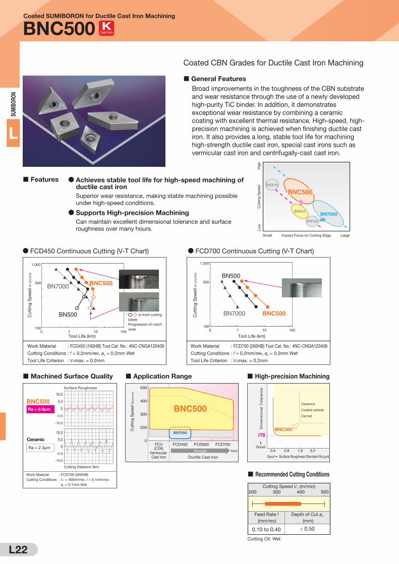
Coated SUMIBORON for Ductile Cast Iron Machining
BNC500
General Features
Broad improvements in the toughness of the CBN substrate
and wear resistance through the use of a newly developed
high-purity TiC binder. In addition, it demonstrates
exceptional wear resistance by combining a ceramic
coating with excellent thermal resistance. High-speed, high-
precision machining is achieved when finishing ductile cast
iron. It also provides a long, stable tool life for machining
high-strength ductile cast iron, special cast irons such as
vermicular cast iron and centrifugally-cast cast iron.
Coated CBN Grades for Ductile Cast Iron Machining
Features D Achieves stable tool life for high-speed machining of ductile cast iron
Superior wear resistance, making stable machining possible
under high-speed conditions.
D Supports High-precision Machining
Can maintain excellent dimensional tolerance and surface
roughness over many hours.Impact Force on Cutting Edge LargeSmall
Cut
ting
Sp
eed
Hig
hLo
w
BNX10
BN500
BN700
BNC500
BN7000
Cutting Speed vc (m/min)
Feed Rate f (mm/rev)
Depth of Cut ap
(mm)
200 300 400 500
0.10 to 0.40 ≤ 0.50
Recommended Cutting Conditions
D FCD450 Continuous Cutting (V-T Chart)
BNC500
BN500
BN7000
Work Material : FCD450 (160HB) Tool Cat. No.: 4NC-CNGA120408
Cutting Conditions : f = 0.2mm/rev, ap = 0.2mm Wet
Tool Life Criterion : vBmax. = 0.2mm
Tool Life (km)
Cu
ttin
g S
peed
vC (m
/min
)
1,000
500
1000 101 100
* is front cutting
blade
Progression of notch
wear
D FCD700 Continuous Cutting (V-T Chart)
BNC500
BN500
BN7000
Work Material : FCD700 (260HB) Tool Cat. No.: 4NC-CNGA120408
Cutting Conditions : f = 0.2mm/rev, ap = 0.2mm Wet
Tool Life Criterion : vBmax. = 0.2mm
Tool Life (km)
1,000
500
1000 101 100
Cu
ttin
g S
peed
vC (m
/min
)
Machined Surface Quality
Work Material : FCD700 (260HB)
Cutting Conditions : vc = 400m/min, f = 0.1mm/rev
ap = 0.1mm Wet
Ceramic
Ra = 2.3μm
Ra = 0.6μm
BNC500
Cutting Distance 3km
Surface Roughness
10.0
5.0
0
-5.0
-10.0
10.0
5.0
0
-5.0
-10.0
500
0
200
300
400
FCD450FCV(CGI)
FCD700FCD600
Ductile Cast Iron
HardStrengthVermicular Cast Iron
Cu
ttin
g S
peed
vC
(m
/min
)
BNC500
BN7000
Application Range
0.4
IT6
0.8 1.6 3.2
BNC500
Surface Roughness Standard Ra (μm)Good
Dim
en
sio
na
l T
ole
ran
ce
Ceramics
Coated carbide
Cermet
Good
High-precision Machining
Cutting Oil: Wet
Cast Iron

L23
M E M O

L24
SUM
IBO
RON
L
SUMIBORON BINDERLESS
NCB100
Nano-polycrystalline CBN
SUMIBORON BINDERLESS NCB100
General Features
SUMIBORON BINDERLESS, which does not contain any binders,
is a CBN sintered product with directly and strongly bonded
nano- to sub-micron CBN particles.
Compared to conventional CBN grades, this provides high
hardness and thermal conductivity, making it highly efficient
with a long tool life when machining exotic alloys such as
titanium alloys and cobalt-chrome alloys.
General Features
Adopts a nano-polycrystalline CBN sintered structure with
hardness and thermal conductivity significantly higher than
conventional sintered CBN. Enables overwhelmingly longer tool life
and improved efficiency and machining accuracy when machining
exotic alloys such as titanium alloys or cobalt-chrome alloys.
Sintered Composition (SEM Image)
Application Range (Machining Titanium Alloy)
Physical Values
Application Range (Machining Cobalt-chrome Alloy)
SUMIBORON BINDERLESS Conventional CBN
CBN Particles 200 to 500nm 500nm
Metal binder
3μm
CBN Particles 1 to 5μm
0
100
200
300
0.05 0.10 0.15 0.20
Feed Rate f (mm/rev)
Cut
ting
Sp
eed
vc
(m/m
in)
NCB100
CBN Content (vol%)
SUMIBORON BINDERLESS
100 90 to 95
WC-Co
41 to 44
100 to 120
51 to 54
180 to 200
Conventional
CBN
Binder
Hardness Hv (GPa)
Thermal Conductivity(W/m·K)
300
Feed Rate f (mm/rev)
Cut
ting
Sp
eed
vc
(m/m
in)
0
100
200
0.05 0.10 0.15 0.20
NCB100
Features
D Ideal for high-efficiency finishing of exotic alloys such
as titanium alloys and cobalt-chrome alloys Exhibits outstanding wear resistance due to the excellent
hardness and thermal conductivity of nano-polycrystalline CBN
D Excellent dimensional tolerance and machined
surface roughness maintained for extended periods Number of tool changes can be drastically reduced compared
to conventional grades, enabling work efficiency to be improved
and total costs to be reduced
Cast Iron Exotic Alloy
Cemented Carbide
Hard BrittleMaterial

L25
SUM
IBORO
N
L
SUMIBORON BINDERLESS
NCB100
D Wear Resistance
D Titanium Alloy
D Others
D Cobalt-chrome alloy
D Cemented Carbide
D Machined Surface Roughness
50 100 150 200 250 300
30 - 35
32 - 38
32 - 38
Ti-6Al-4V
Ti-5Al-5V-5Mo-3Cr
Ti-10V-2Fe-3Al
Work Material
Grade
Recommended Cutting Conditions
Cutting Speed vc (m/min) Feed Rate f(mm/rev)
Depth of Cut ap
(mm)Composition
Hardness(HRC)
0.05
0.05
0.05
-
-
-
-
-
-
0.20
0.20
0.20
0.15
0.10
0.10
0.10
0.10
0.10
-
-
-
-
-
-
0.50
0.50
0.50
0.30
0.30
0.30
NCB100
NCB100
NCB100
Min. - Optimum - Max.
10 100 200 300 400
130 - 230
1,000 - 1,500
Pure Titanium
Work Material
Grade
Recommended Cutting Conditions
Cutting Speed vc (m/min) Feed Rate f(mm/rev)
Depth of Cut ap
(mm)Composition/Material
Hardness(HV) 50
0.05
0.05
-
-
-
-
0.20
0.20
0.10
0.10
0.10
0.10
-
-
-
-
0.50
0.30
0.30
0.20
NCB100
NCB100
Min. - Optimum - Max.
Cermet Material(Ferrous metal including binder)
50 100 150 200
35 - 45Co-30Cr-5Mo
Work Material
Grade
Recommended Cutting Conditions
Cutting Speed vc (m/min) Feed Rate f(mm/rev)
Depth of Cut ap
(mm)Composition
Hardness(HRC)
0.05 - - 0.200.15 0.10 - - 0.300.15NCB100
Min. - Optimum - Max.
5 10 15 20 25 30 35 40
Less than 85
WC-20Co
Work Material
Grade
Recommended Cutting Conditions
Cutting Speed vc (m/min) Feed Rate f(mm/rev)
Depth of Cut ap
(mm)Composition
Hardness(HRA)
0.03 - - 0.200.10 0.03 - - 0.200.10NCB100
Min. - Optimum - Max.
Cutting Performance (Machining Titanium Alloy)
Recommended Cutting Conditions
Fla
nk W
ear
Wid
th (m
m)
0
0.1
0.2
0.3
0.4
10 20 30 40
Cutting Distance (km)
F
F
FF
DDDDD
D DD D
DD
DD
DNCB100Conventional PCD
Conventional
CBN
Carbide
Work Material : Titanium Alloy (Ti-6Al-4V)
Tool Cat. No. : CNGA120408
Cutting Conditions : Vc = 150m/min, f = 0.15mm/rev
ap = 0.5mm Wet (High Pressure Coolant)
Cutting Distance (km)
0
NCB100
Conventional PCD
Conventional CBNCarbide
3.0
4.0
5.0
6.0
7.0
8.0
10 20 30 40
F
FFDDD
DDDDDDDDDDD Theoretical Surface
Roughness
D
Su
rface F
inis
h R
z (μ
m)
Work Material : Titanium Alloy (Ti-6Al-4V)
Tool Cat. No. : CNGA120408
Cutting Conditions : Vc = 150m/min, f = 0.15mm/rev
ap = 0.5mm Wet (High Pressure Coolant)
NCB100(After Cutting 1km)
NCB100(After Cutting 35km)
Conventional PCD
(After Cutting 1km)
0
-2.5
2.5
0
-2.5
2.5
0
-2.5
2.5
Rz3.6μm
Rz4.2μm
Rz6.2μm
(μm)
*SUMIDIA BINDERLESS NPD10 is recommended for cemented carbide machining of 83HRA or more.
D Wear Resistance D Machined Surface Roughness
Cutting Performance (Machining Cobalt-chrome Alloy)
Cutting Distance (km)Fla
nk W
ear
Wid
th (m
m)
NCB100vc=150mm/min
vc=60mm/min
Carbide
Cermet
0
0.1
0.2
0.3
0.5 1.0 1.5
DDDDDDDDDD
DDDDDDDD
Work Material : Cobalt-chrome alloy (forging)
Tool Cat. No. : VNGA160408
Cutting Conditions : Vc = 60,150m/min f = 0.1mm/rev
ap = 0.4mm Wet
0
0.4
0.6
0.8
1.0
0.5 1.0 1.5
Cutting Distance (km)
D D D D D D D DNCB100
Carbide
Cermet
Theoretical Surface
Roughness
Su
rface F
inis
h R
a (μ
m)
Work Material : Cobalt-chrome alloy (forging)
Tool Cat. No. : VNGA160408
Cutting Conditions : Vc = 60m/min f = 0.1mm/rev
ap = 0.4mm Wet
NCB100(After Cutting 0.5km)
Carbide
(After Cutting 0.5km)
Cermet
(After Cutting 0.5km)
0
-2.0
2.0
(μm)
0
-2.0
2.0
(μm)
0
-2.0
2.0
(μm)
Rz 2.2μm
Rz 6.0μm
Rz 4.7μm
Cast Iron Exotic Alloy
Cemented Carbide
Hard BrittleMaterial

L26
SUM
IBO
RON
L
SUMIBORON
Insert Cat. No. Identification Table
C N M AExample
(2) Relief Angle
Refer to Table 2
(3) Tolerance
Refer to Table 3
(4) Insert Hole
Refer to Table 4
(1) Insert Shape
Refer to Table 1
(1) (2) (3) (4)
Regrindable Type
C N G AExample
(2) Relief Angle
Refer to Table 2
(3) Tolerance
Refer to Table 3
(4) Insert Hole
Refer to Table 4
(1) Insert Shape
Refer to Table 1
(1) (2) (3) (4)(9) (10)
(9) No. of Cutting Edges
Refer to Table 9
(10) Type Code
Refer to Table 10
NU -2 One-use Type(Disposable)
Symbol Insert Shape Apex Angle
CDiamond Type
80˚
D 55˚
V 35˚
R Round Type Q
S Square Type 90˚
T Triangular Type 60˚
W Trigon Type 80˚
Table 1: (1) Insert Shape
Symbol Relief Angle
B 5˚
C 7˚
N 0˚
P 11˚
Table 2: (2) Relief Angle
Symbol Tolerance of Nose Height (mm)
Tolerance of Inscribed Circle (mm)
Thickness Tolerance (mm)
E ± 0.025 ± 0.025 ± 0.025
G ± 0.025 ± 0.025 ± 0.13
M ± 0.08 to ± 0.2 ± 0.05 to ± 0.15 ± 0.13
Generally, these inserts have unground side faces Refer to page B2 for details on M Class precision
Table 3: (3) Tolerance
SymbolHoleY/N
Shape(Cross Section) Symbol Shape
(Cross Section)
N NoNo
YesYes
No ACylinderShape
No
M OneFace
G Double-sided
WStraight
Hole +
SingleChamfer(40˚ to 60˚)
No
T OneFace
X Q Q Q Special
Table 4: (4) Insert Hole Table 9: (9) No. of Cutting Edges
SymbolNo. of
Cutting Edges Type
No
2346
1
2
3
4
6
1-Cornered Type
Multi-CorneredType
Table 10: (10) Type Code (One-use Type)
Symbol Type Grade
NC Coated SUMIBORONBNC2115,BNC2125,BNC2010,BNC2020,BNC100,BNC160,BNC200,BNC300,BNC500
NU Uncoated SUMIBORON
SUMIBORON BINDERLESS
BNX10,BNX20,BN1000,BN2000,BN350,BN500,BN7000,BN700,BN7115,BN7500
NCB100
NS Uncoated SUMIBORON BNX25
*The NS type is a single-use insert for the BNX25 grade, using the latest brazing technique. The shape is the same as the NU type.*Cat. numbers that begin with a "T-" are 10-piece packs
HoleStyle Chipbreaker ChipbreakerHole
Y/NHoleStyle
Codes (1), (2), (3) and (4) show typical examples.

L27
SUM
IBORO
N
L
SUMIBORON
Insert Cat. No. Identification Table
12 04 08 (-)B(5) (6) (7) (8)
(6) Thickness
Refer to Table 6
(7) Corner Radius
Refer to Table 7
(8) Additional Information
Refer to Table 8
(5) Cutting Edge Length
Refer to Table 5
12 04 08 LT(5) (6) (7) (8)
(6) Thickness
Refer to Table 6
(7) Corner Radius
Refer to Table 7
(8) Additional Information
Refer to Table 8
(5) Cutting Edge Length
Refer to Table 5
Symbol Corner Radius (mm)
00 Sharp Edge
01 0.1
02 0.2
04 0.4
08 0.8
12 1.2
16 1.6
20 2.0
24 2.4
Table 7: (7) Corner Radius
Symbol Thickness (mm)
X1 *
01 1.59
02 2.38
03 3.18
T3 3.97
04 4.76
06 6.35
(*)CC T03X1 Insert Thickness: 1.40
CC T04X1 Insert Thickness: 1.80
Table 6: (6) Thickness
Symbol SymbolOld symbol
No
(-)B
-BSTN
LF
LE
LT
LS
ES
HT
HS
US
No
(-)B
-BSN
F
S
M
Q
T
Q
WG
WH
W
LFW
N-FV
N-LV
N-SV
Table 8: (8) Additional Information
Shape Symbol Cutting Edge Length (Side Length)
InscribedCircle Shape Symbol Cutting Edge Length
(Side Length)
(mm)
Negative PositiveNegative PositiveInscribed Circle Shape Symbol
Cutting Edge Length (Side Length) Inscribed Circle
C80˚
DiamondType
D55˚
DiamondType
07 7.7 6.35
WTrigonType
04 4.97 4.30
06 6.4 6.35
11 11.6 9.525
08 8.0 7.94
15 15.5 12.70
06
09 9.7 9.525
08
12 12.9 12.70
8.7 12.70
V35˚
DiamondType
08 8.3 4.76
11 11.1 6.35
16 16.6 9.525
SSquareType
09 9.525 9.525
12 12.70 12.70
TTriangular
Type
06 6.9 3.97
08 8.2 4.76
09 9.6 5.56
11 11.0 6.35
16 16.5 9.525
22 22.0 12.70
RRoundType
09
12
9.525
12.70
9.525
12.70
Table 5: (5) Cutting Edge Length (Typical Examples) Note: Cutting edge length indicated is measured without nose radiuses.
3.2
4.6
3.97
4.76
Uncoated Coated
Code Description Code Description
Standard Cutting Edge
Full-top CBN Type
Full-top CBN Type (emphasis on edge sharpness)
Sharp Edge Type
Emphasis on Edge Sharpness
Strong Edge Type
Strong Edge Type
Wiper Insert Type
Wiper Sharp Edge Type
Chipbreaker Type
General-purpose Type for Continuous Cutting
Q
Emphasis on Edge Sharpness
High-efficiency Type
For the One-use Type, cutting edge length indicates side length.See L32 on for the One-use Type cutting edge length
L30
Codes (5), (6) and (7) show typical examples.
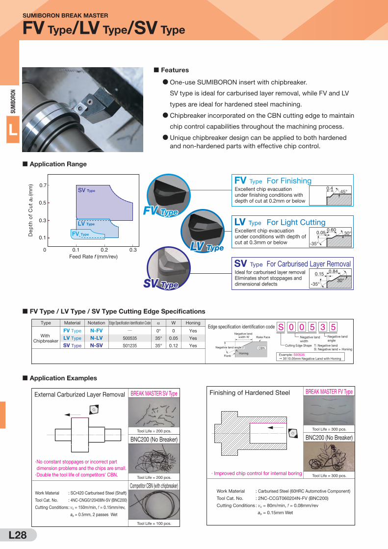
L28
SUM
IBO
RON
L
Application Range
Application Examples
External Carburized Layer Removal
Work Material : SCr420 Carburised Steel (Shaft)
Tool Cat. No. : 4NC-CNGG120408N-SV (BNC200)
Cutting Conditions : vc = 150m/min, f = 0.15mm/rev,
ap = 0.5mm, 2 passes Wet
BREAK MASTER SV Type
BNC200 (No Breaker)
Tool Life = 200 pcs.
Tool Life = 200 pcs.
Tool Life = 100 pcs.
Competitor CBN (with chipbreaker)
· No constant stoppages or incorrect part
dimension problems and the chips are small.
· Double the tool life of competitors' CBN.
Finishing of Hardened Steel
Work Material : Carburised Steel (60HRC Automotive Component)
Tool Cat. No. : 2NC-CCGT060204N-FV (BNC200)
Cutting Conditions : vc = 80m/min, f = 0.08mm/rev
ap = 0.15mm Wet
BREAK MASTER FV Type
BNC200 (No Breaker)
Tool Life = 300 pcs.
Tool Life = 300 pcs.· Improved chip control for internal boring
Features
D One-use SUMIBORON insert with chipbreaker.
SV type is ideal for carburised layer removal, while FV and LV
types are ideal for hardened steel machining.
D Chipbreaker incorporated on the CBN cutting edge to maintain
chip control capabilities throughout the machining process.
D Unique chipbreaker design can be applied to both hardened
and non-hardened parts with effective chip control.
SV TypeSV Type
0.1 0.2 0.30
0.1
0.3
0.5
0.7
Feed Rate f (mm/rev)
De
pth
of
Cu
t a p
(mm
)
LV Type For Light CuttingExcellent chip evacuation under conditions with depth of cut at 0.3mm or below
0.60
-35°
30°
SV Type For Carburised Layer RemovalIdeal for carburised layer removal Eliminates short stoppages and dimensional defects
0.15
-35°30°
0.84
SV Type
FV Type For FinishingExcellent chip evacuation under finishing conditions with depth of cut at 0.2mm or below
45°0.4
FV Type
LV Type
LV TypeLV Type
FV TypeFV Type
Cutting Edge Shape T: Negative landS: Negative land + Honing
Example: S00535 35°/0.05mm Negative Land with Honing
Negative land width
Negative land angle
S 0 0 5 3 5Edge specification identification code
Rake FaceNegative land
width W
Flank
CBN
Honing
Negative land angle
FV Type / LV Type / SV Type Cutting Edge Specifications
NotationType Honing
N-FV
N-LV
N-SV
FV Type
LV Type
SV Type
Edge Specification Identification Code
QS00535
S01235
0°
35°
35°
W
0
0.05
0.12
Yes
Yes
Yes
With Chipbreaker
Material
0.05
SUMIBORON BREAK MASTER
FV Type/LV Type/SV Type
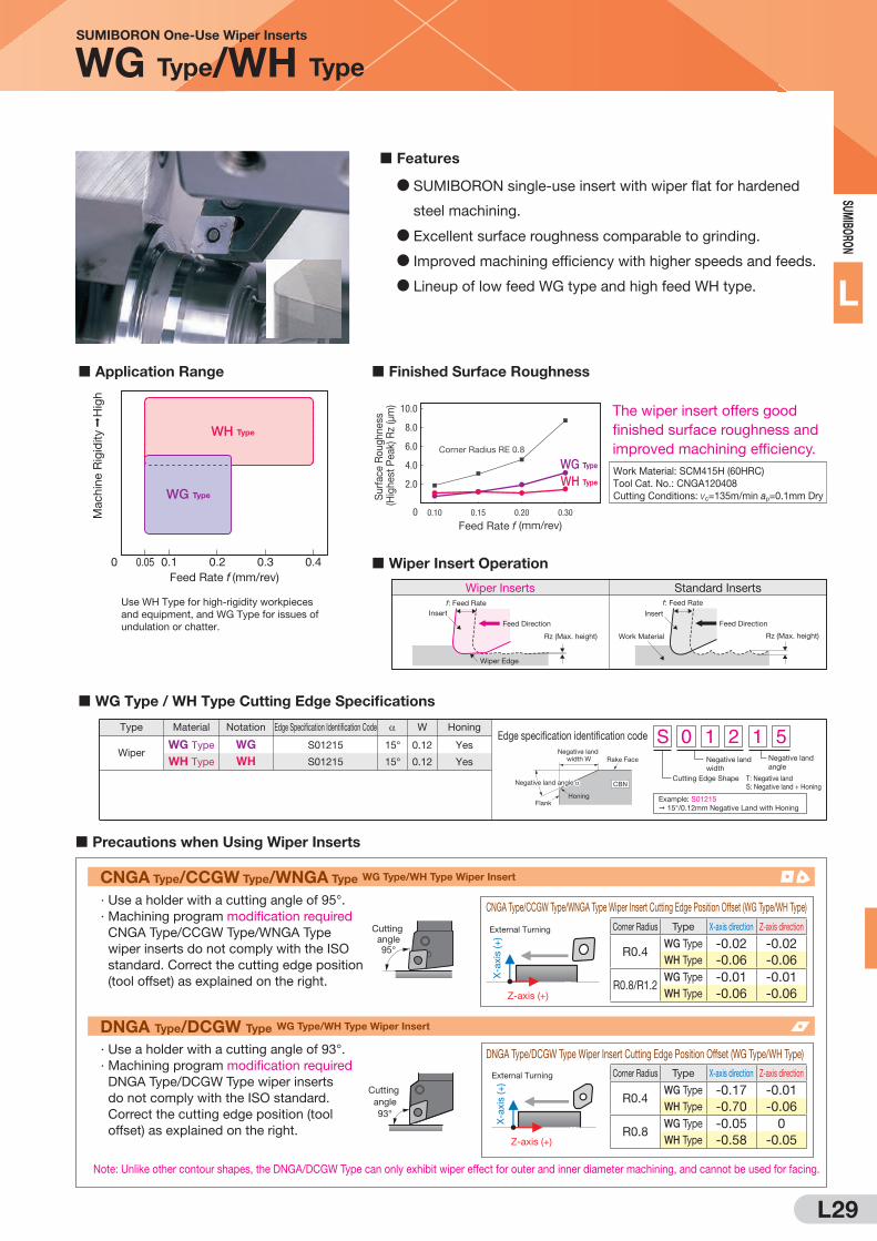
L29
SUM
IBORO
N
L
Features
D SUMIBORON single-use insert with wiper flat for hardened
steel machining.
D Excellent surface roughness comparable to grinding.
D Improved machining efficiency with higher speeds and feeds.
D Lineup of low feed WG type and high feed WH type.
X-a
xis
(+
)
Z-axis (+)
External Turning
CNGA Type/CCGW Type/WNGA Type Wiper Insert Cutting Edge Position Offset (WG Type/WH Type)
Corner Radius Type X-axis direction Z-axis direction
R0.4WG Type -0.02 -0.02
WH Type -0.06 -0.06
R0.8/R1.2WG Type -0.01 -0.01
WH Type -0.06 -0.06
CNGA Type/CCGW Type/WNGA Type WG Type/WH Type Wiper Insert
· Use a holder with a cutting angle of 95°.
· Machining program modification required
CNGA Type/CCGW Type/WNGA Type
wiper inserts do not comply with the ISO
standard. Correct the cutting edge position
(tool offset) as explained on the right.
Cutting angle95°
Cutting angle93°
X-a
xis
(+
)
Z-axis (+)
External Turning Corner Radius Type X-axis direction Z-axis direction
R0.4WG Type -0.17 -0.01
WH Type -0.70 -0.06
R0.8WG Type -0.05 0
WH Type -0.58 -0.05
DNGA Type/DCGW Type Wiper Insert Cutting Edge Position Offset (WG Type/WH Type)
DNGA Type/DCGW Type WG Type/WH Type Wiper Insert
· Use a holder with a cutting angle of 93°.
· Machining program modification required
DNGA Type/DCGW Type wiper inserts
do not comply with the ISO standard.
Correct the cutting edge position (tool
offset) as explained on the right.
Note: Unlike other contour shapes, the DNGA/DCGW Type can only exhibit wiper effect for outer and inner diameter machining, and cannot be used for facing.
Precautions when Using Wiper Inserts
Cutting Edge Shape T: Negative landS: Negative land + Honing
Example: S01215 15°/0.12mm Negative Land with Honing
Negative land width
Negative land angle
S 0 1 2 1 5Edge specification identification code
Rake FaceNegative land
width W
Flank
CBN
Honing
Negative land angle
WG Type / WH Type Cutting Edge Specifications
NotationType W Honing
WGWH
WG Type
WH Type
Edge Specification Identification Code
S01215
S01215
15°
15°
0.12
0.12
Yes
YesWiper
Material
0.10.05 0.2 0.40.30Feed Rate f (mm/rev)
Mac
hine
Rig
idity
H
igh
Application Range Finished Surface Roughness
Wiper Insert Operation
Wiper Inserts Standard Insertsf: Feed Rate
Rz (Max. height)
Feed Direction
Wiper Edge
Insert Insert
Work Material
f: Feed Rate
Rz (Max. height)
Feed Direction
WG Type
WH Type
Feed Rate f (mm/rev)0
Corner Radius RE 0.8
2.0
4.0
6.0
8.0
10.0
0.10 0.15 0.20 0.30
D
DD
DDDDD
Work Material: SCM415H (60HRC)Tool Cat. No.: CNGA120408Cutting Conditions: vc=135m/min ap=0.1mm Dry
The wiper insert offers good finished surface roughness and improved machining efficiency.
Use WH Type for high-rigidity workpieces and equipment, and WG Type for issues of undulation or chatter.
WG Type
WH Type
Sur
face
Rou
ghne
ss
(Hig
hest
Pea
k) R
z (μ
m)
SUMIBORON One-Use Wiper Inserts
WG Type/WH Type
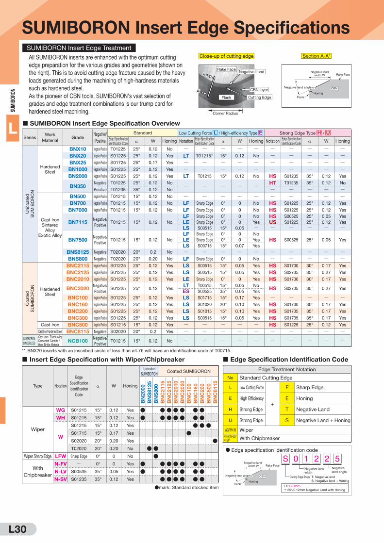
L30
SUM
IBO
RON
L
SUMIBORON Insert Edge SpecificationsSUMIBORON Insert Edge Treatment
All SUMIBORON inserts are enhanced with the optimum cutting
edge preparation for the various grades and geometries (shown on
the right). This is to avoid cutting edge fracture caused by the heavy
loads generated during the machining of high-hardness materials
such as hardened steel.
As the pioneer of CBN tools, SUMIBORON's vast selection of
grades and edge treatment combinations is our trump card for
hardened steel machining.
SUMIBORON Insert Edge Specification Overview
SeriesWork
MaterialGrade
Negative/
Positive
Standard Low Cutting Force L / High-efficiency Type E Strong Edge Type H / UEdge Specification Identification Code
W Honing NotationEdge Specification Identification Code
W Honing NotationEdge Specification Identification Code
W Honing
Un
co
ate
d
SU
MIB
OR
ON
Hardened
Steel
BNX10 Negative/Positive T01225 25° 0.12 No Q Q Q Q Q Q Q Q Q QBNX20 Negative/Positive S01225 25° 0.12 Yes LT T01215*1 15° 0.12 No Q Q Q Q QBNX25 Negative/Positive S01725 25° 0.17 Yes Q Q Q Q Q Q Q Q Q QBN1000 Negative/Positive S01225 25° 0.12 Yes Q Q Q Q Q Q Q Q Q QBN2000 Negative/Positive S01225 25° 0.12 Yes LT T01215 15° 0.12 No HS S01235 35° 0.12 Yes
BN350Negative T01225 25° 0.12 No
Q Q Q Q QHT T01235 35° 0.12 No
Positive T01235 35° 0.12 No Q Q Q Q Q
Cast Iron
Sintered
Alloy
Exotic Alloy
BN500 Negative/Positive T01215 15° 0.12 No Q Q Q Q Q Q Q Q Q QBN700 Negative/Positive T01215 15° 0.12 No LF Sharp Edge 0° 0 No HS S01225 25° 0.12 Yes
BN7000 Negative/Positive T01215 15° 0.12 No LF Sharp Edge 0° 0 No HS S01225 25° 0.12 Yes
BN7115Negative/
PositiveT01215 15° 0.12 No
LF Sharp Edge 0° 0 No HS S00525 25° 0.05 Yes
LE Sharp Edge 0° 0 Yes US S01225 25° 0.12 Yes
LS S00515 15° 0.05 Q Q Q Q Q Q
BN7500Negative/
PositiveT01215 15° 0.12 No
LF Sharp Edge 0° 0 No
HS S00525 25° 0.05 YesLE Sharp Edge 0° 0 Yes
LS S00715 15° 0.07 Yes
BNS8125 Negative T02020 20° 0.2 No Q Q Q Q Q Q Q Q Q QBNS800 Negative T02020 20° 0.20 No LF Sharp Edge 0° 0 No Q Q Q Q Q
Co
ate
d
SU
MIB
OR
ON
Hardened
Steel
BNC2115 Negative/Positive S01225 25° 0.12 Yes LS S00515 15° 0.05 Yes HS S01730 30° 0.17 Yes
BNC2125 Negative/Positive S01225 25° 0.12 Yes LS S00515 15° 0.05 Yes HS S02735 35° 0.27 Yes
BNC2010 Negative/Positive S01225 25° 0.12 Yes LE Sharp Edge 0° 0 Yes HS S01730 30° 0.17 Yes
BNC2020Negative/
PositiveS01225 25° 0.12 Yes
LT T00515 15° 0.05 NoHS S02735 35° 0.27 Yes
ES S00535 35° 0.05 Yes
BNC100 Negative/Positive S01225 25° 0.12 Yes LS S01715 15° 0.17 Yes Q Q Q Q QBNC160 Negative/Positive S01225 25° 0.12 Yes LS S01020 20° 0.10 Yes HS S01730 30° 0.17 Yes
BNC200 Negative/Positive S01225 25° 0.12 Yes LS S01015 15° 0.10 Yes HS S01735 35° 0.17 Yes
BNC300 Negative/Positive S01225 25° 0.12 Yes LS S00515 15° 0.05 Yes HS S01735 35° 0.17 Yes
Cast Iron BNC500 Negative/Positive S01215 15° 0.12 Yes Q Q Q Q Q HS S01225 25° 0.12 Yes
Cast Iron/Hardened Steel BNC8115 Negative S02020 20° 0.2 Yes Q Q Q Q Q Q Q Q Q QSUMIBORON
BINDERLESS
Cast Iron / Exotic Alloy Cemented Carbide / Hard Brittle Material
NCB100Negative/
PositiveT01215 15° 0.12 No Q Q Q Q Q Q Q Q Q Q
*1 BNX20 inserts with an inscribed circle of less than ø4.76 will have an identification code of T00715.
Close-up of cutting edge
Corner Radius
Rake Face
Flank
Negative Land
CBN layer
Cutting Edge
AA
A'A'
Section A-A'
Rake FaceNegative land
width W
Flank
CBN
Honing
Negative land angle
Edge Specification Identification Code
Edge Treatment Notation
No Standard Cutting Edge
L Low Cutting Force
+
F Sharp Edge
E High Efficiency E Honing
H Strong Edge T Negative Land
U Strong Edge S Negative Land + Honing
WG/WH/W Wiper
N-FV/N-LV/ N-SV With Chipbreaker
Insert Edge Specification with Wiper/Chipbreaker
Cutting Edge Shape T: Negative land
S: Negative land + Honing
EX: S01225
25°/0.12mm Negative Land with Honing
Negative land
width
Negative
land angle
S 0 1 2 2 5D Edge specification identification code
Rake FaceNegative land
width W
Flank
CBN
Honing
Negative land angle
Type Notation
Edge
Specification
Identification
Code
W Honing
Uncoated
SUMIBORONCoated SUMIBORON
BN
20
00
BN
S8
12
5
BN
S8
00
BN
C2
11
5
BN
C2
12
5
BN
C2
01
0
BN
C2
02
0
BN
C1
00
BN
C1
60
BN
C2
00
BN
C5
00
BN
C8
11
5
Wiper
WG S01215 15° 0.12 Yes ● ●●●● ●●WH S01215 15° 0.12 Yes ● ●●●● ●●
W
S01215 15° 0.12 Yes ●●●S01715 15° 0.17 Yes ●S02020 20° 0.20 Yes ●T02020 20° 0.20 No ●●
Wiper Sharp Edge LFW Sharp Edge 0° 0 No ●
With
Chipbreaker
N-FV Q 0° 0 Yes ● ●●●● ●●N-LV S00535 35° 0.05 Yes ● ●●●● ●●N-SV S01235 35° 0.12 Yes ●●●● ●●
●mark: Standard stocked item

L31
SUM
IBORO
N
L
SUMIBORON Insert Edge Specifications Edge Treatment Performance
Machining of Hardened Steel
Comparison of Cutting Force with Coated SUMIBORON (vc = 100mm/min) Work Material:
SCM415H
Tool Cat. No.:
DNGA150408
Cutting Conditions:
vc = 100m/min
f = 0.1mm/rev
ap = 0.1mm
Dry
LE Type LT Type LS Type ES Type Standard Type HS Type
Cu
ttin
g F
orc
e (
N)
0
20
40
60
80
100
110
10
30
50
70
90
(T00515) (S00515) (S00535) (S01225) (S02735)Without Negative Land With Honing
Leg
en
d
Principal Force
Feed Force
Back Force
Cutting Force Comparison (Feed Rate: f = 0.05mm/rev) Work Material:
F-08C2 equivalent
Tool Cat. No.:
CNGA120408
Cutting Conditions:
vc = 200m/min
f = 0.05mm/rev
ap = 0.2mm
Dry
LE TypeLF Type LS Type Standard Type HS Type US Type
(S00715) (T01215) (S00525) (S01225)
Cu
ttin
g F
orc
e (
N)
10
20
30
40
50
60
0
Sharp Edge Without Honing
Without Negative Land With Honing
Leg
en
d
Principal Force
Feed Force
Back Force
Comparison of Cutting Force with Coated SUMIBORON (vc = 200mm/min) Work Material:
SCM415H
Tool Cat. No.:
DNGA150408
Cutting Conditions:
vc=200m/min
f = 0.1mm/rev
ap = 0.1mm
Dry
20
40
60
80
100
110
0
10
30
50
70
90
LE Type LT Type LS Type ES Type Standard Type HS Type
(T00515) (S00515) (S00535) (S01225) (S02735)
Cu
ttin
g F
orc
e (
N)
Without Negative Land With Honing
Leg
en
d
Principal Force
Feed Force
Back Force
Relationship between Cutting Edge Treatment and Machining Quality
ø12
0m
m
ø6
0m
m
GoodSurface Roughness
Burr
vc = 100m/min vc = 200m/min vc = 300m/min
Small
Go
od
Su
rface R
ou
gh
ness
Bu
rrS
mall
LF Type
Standard Type
HS Type
Work Material: F-08C2 equivalent
Tool Cat. No.: 3NU-TNGA 160408 (BN7500)
Edge Specification: LF Type, Standard, HS Type
Cutting Conditions: vc = 100, 200, 300m/min
f = 0.1mm/rev
ap = 0.2mm
Wet
Go
od
Cutti
ng E
dge
Shar
pnes
s
Frequency of Interruption Heavy
StandardR Honing
LE Type
R Honing
LT Type
No R Honing
LS Type
R Honing
ES Type
R Honing
HT Type
HS TypeR Honing
No R Honing
Emphasis on Dimensional
Tolerance and Surface Roughness
Suppressed Breakage at
High Speeds/High Feeds
Emphasis on Dimensional Tolerance and Burr Control
Burr Control for Interrupted Cutting
Suppressed Breakage with Interrupted Cutting
H
Machining of Sintered Alloy
Go
od
Cut
ting
Edge
Sha
rpne
ss
Burr Control EmphasisedLF Type
No R Honing
LE Type
R Honing
LS Type
R Honing
HS Type
R Honing
StandardNo R Honing
US Type
R Honing
Surface Roughness Emphasised
Breakage Control Emphasised
Frequency of Interruption Heavy
Sintered Alloy
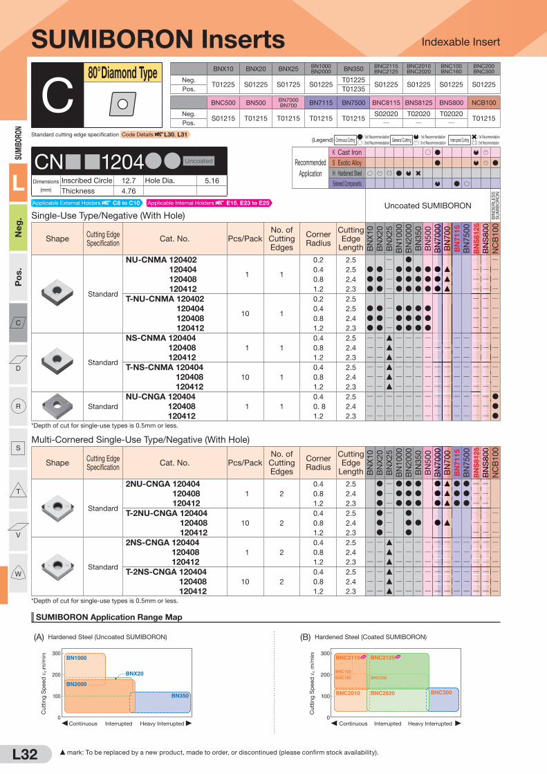
L32
SUMIBORON Application Range Map
(A) Hardened Steel (Uncoated SUMIBORON) (B) Hardened Steel (Coated SUMIBORON)
300
200
100
0Heavy InterruptedContinuous Interrupted
BNX20
BN1000
BN350
BN2000
Cu
ttin
g S
peed
vc
( m/m
in) 300
200
100
0Heavy InterruptedContinuous Interrupted
BNC2010 BNC2020
BNC160
BNC100
BNC200
BNC2115 BNC2125
BNC300
Cu
ttin
g S
peed
vc
( m/m
in)
Indexable Insert
SUM
IBO
RON
L
Ne
g.
Po
s.
C
D
R
S
T
V
W
BNX10 BNX20 BNX25BN1000BN2000 BN350
BNC2115BNC2125
BNC2010BNC2020
BNC100BNC160
BNC200BNC300
Neg.T01225 S01225 S01725 S01225
T01225S01225 S01225 S01225 S01225
Pos. T01235
BNC500 BN500BN7000BN700 BN7115 BN7500 BNC8115 BNS8125 BNS800 NCB100
Neg.S01215 T01215 T01215 T01215 T01215
S02020 T02020 T02020T01215
Pos. Q Q Q
(Legend) Continuous Cutting : 1st Recommendation
General Cutting : 1st Recommendation
Interrupted Cutting : 1st Recommendation
: 2nd Recommendation : 2nd Recommendation : 2nd Recommendation
Recommended
Application
K Cast Iron
S Exotic Alloy
H Hardened Steel
Sintered Components
Multi-Cornered Single-Use Type/Negative (With Hole)
ShapeCutting Edge Specification
Cat. No. Pcs/PackNo. of Cutting Edges
Corner Radius
Cutting Edge
Length BN
X10
BN
X20
BN
X25
BN
1000
BN
2000
BN
350
BN
500
BN
7000
BN
700
BN
71
15
BN
7500
BN
S8125
BN
S800
NC
B100
Standard
2NU-CNGA 120404
1 2
0.4 2.5 D Q D D D D F D D Q Q2NU-CNGA 120408 0.8 2.4 D Q D D D D F D D Q Q2NU-CNGA 120412 1.2 2.3 D Q D D D D F D D Q QT-2NU-CNGA 120404
10 2
0.4 2.5 D Q D Q Q QT-2NU-CNGA 120408 0.8 2.4 D Q D D D F Q Q QT-2NU-CNGA 120412 1.2 2.3 D Q D Q Q Q
Standard
2NS-CNGA 120404
1 2
0.4 2.5 Q Q F Q Q Q Q Q Q Q Q Q Q Q2NS-CNGA 120408 0.8 2.4 Q Q F Q Q Q Q Q Q Q Q Q Q Q2NS-CNGA 120412 1.2 2.3 Q Q F Q Q Q Q Q Q Q Q Q Q QT-2NS-CNGA 120404
10 2
0.4 2.5 Q Q F Q Q Q Q Q Q Q Q Q Q QT-2NS-CNGA 120408 0.8 2.4 Q Q F Q Q Q Q Q Q Q Q Q Q QT-2NS-CNGA 120412 1.2 2.3 Q Q F Q Q Q Q Q Q Q Q Q Q Q
*Depth of cut for single-use types is 0.5mm or less.
SUMIBORON Inserts
Single-Use Type/Negative (With Hole)Uncoated SUMIBORON
BIN
DE
RL
ES
S
SU
MIB
OR
ON
ShapeCutting Edge Specification
Cat. No. Pcs/PackNo. of Cutting Edges
Corner Radius
Cutting Edge
Length BN
X10
BN
X20
BN
X25
BN
1000
BN
2000
BN
350
BN
500
BN
7000
BN
700
BN
71
15
BN
7500
BN
S8125
BN
S800
NC
B100
Standard
NU-CNMA 120402
1 1
0.2 2.5 Q D Q Q QNU-CNMA 120404 0.4 2.5 D D Q D D D D D F Q Q QNU-CNMA 120408 0.8 2.4 D D Q D D D D D F Q Q QNU-CNMA 120412 1.2 2.3 D D Q D D D D D F Q Q QT-NU-CNMA 120402
10 1
0.2 2.5 Q Q Q QT-NU-CNMA 120404 0.4 2.5 D D Q D D D D Q Q QT-NU-CNMA 120408 0.8 2.4 D D Q D D D D Q Q QT-NU-CNMA 120412 1.2 2.3 D D Q D D D D Q Q Q
Standard
NS-CNMA 120404
1 1
0.4 2.5 Q Q F Q Q Q Q Q Q Q Q Q Q QNS-CNMA 120408 0.8 2.4 Q Q F Q Q Q Q Q Q Q Q Q Q QNS-CNMA 120412 1.2 2.3 Q Q F Q Q Q Q Q Q Q Q Q Q QT-NS-CNMA 120404
10 1
0.4 2.5 Q Q F Q Q Q Q Q Q Q Q Q Q QT-NS-CNMA 120408 0.8 2.4 Q Q F Q Q Q Q Q Q Q Q Q Q QT-NS-CNMA 120412 1.2 2.3 Q Q F Q Q Q Q Q Q Q Q Q Q Q
Standard
NU-CNGA 120404
1 1
0.4 2.5 Q Q Q Q Q Q Q Q Q Q Q Q Q DNU-CNGA 120408 0. 8 2.4 Q Q Q Q Q Q Q Q Q Q Q Q Q DNU-CNGA 120412 1.2 2.3 Q Q Q Q Q Q Q Q Q Q Q Q Q D
*Depth of cut for single-use types is 0.5mm or less.
C80° Diamond Type
CN 1204DD Uncoated
Dimensions
(mm)
Inscribed Circle 12.7 Hole Dia. 5.16
Thickness 4.76
Standard cutting edge specification Code Details L30, L31
Applicable External Holders C8 to C10 Applicable Internal Holders E15, E23 to E25
BN
BN
70
7000
00
BN
BN
70
7000
00
BN
BN
BN
70
70
70
000B
NB
NB
N70
70
70000
BN
BN
BN
S8
S8
S800
00
00
BN
BN
BN
S8
S8
S8
00
00
00
DDDDDDDDD
QQQQQQQQQQQQQQQQQQQQQQQQQQQ
DDDDDDDDD
DDD
QQQQQQQQQQQQQQQQQQ
QQQQQQQQQQQQQQQQQQQQQQQQQQQQQQQQQQQQQQQ
QQQQQQQQQQQQQQQQQQQQQQQQQQ
FFFFFFFFF
QQQQQQQQQQQQQQQQQQQQQQQQQQQ
FFFFFFFFF
FFF
QQQQQQQQQQQQQQQQQQ
QQQQQQQQQQQQQQQQQQQQQQQQQQQQQQQQQQQQQQQQQQQQQQQQQQQ
QQQQQQQQQQQQQQQQQQQQQQQQQQQQQQQQQQQQ
F mark: To be replaced by a new product, made to order, or discontinued (please confirm stock availability).

L33
SUMIBORON Application Range Map
(C) Gray Cast Iron (D) Ductile Cast Iron (E) General Sintered Alloy (F) High-density Sintered Alloy (G) Titanium Alloy
0 1.0 2.0 3.0
300
500
200
400
Depth of Cut ap (mm)
BNC500
BNC8115
BNS8125BN7000
Cutt
ing
Sp
eed
vc
( m/m
in)
100
200
300
Depth of Cut ap(mm)
Feed Rate f(mm/rev)
0 0.1
0.150.10.05 0.2 0.25 0.3
0.2 0.3 0.4 0.5
Finishing region
Roughing region
BN7500BN7115 BN7000
Cutt
ing
Sp
eed
vc
( m/m
in)
Depth of Cut ap(mm)
Feed Rate f(mm/rev)
0 0.1
0.150.10.05 0.2 0.25 0.3
0.2 0.3 0.4 0.5
100
200
300
Finishing region
Roughing region
BN7500BN7115 BN7000
Cutt
ing
Sp
eed
vc
( m/m
in)
0
100
200
300
0.05 0.10 0.15 0.20
Feed Rate f (mm/rev)
NCB100
Cutt
ing
Sp
eed
vc
( m/m
in)Finishing
regionRoughing region
0 1.0 2.0 3.0 4.0
1,000
2,000
2,500
500
1,500
Depth of Cut ap (mm)
BNS800
BN7000
BN500
BNC8115BNS8125
Cutt
ing
Sp
eed
vc
( m/m
in)
Indexable Insert
SUM
IBORO
N
L
Ne
g.
Po
s.
C
D
R
S
T
V
W
(Legend) Continuous Cutting : 1st Recommendation
General Cutting : 1st Recommendation
Interrupted Cutting : 1st Recommendation
: 2nd Recommendation : 2nd Recommendation : 2nd Recommendation
Recommended
Application
K Cast Iron
S Exotic Alloy
H Hardened Steel
Sintered Components
SUMIBORON Inserts
Multi-Cornered Single-Use Type/Negative (With Hole)Uncoated SUMIBORON
BIN
DE
RL
ES
S
SU
MIB
OR
ON
ShapeCutting Edge Specification
Cat. No. Pcs/PackNo. of Cutting Edges
Corner Radius
Cutting Edge
Length BN
X10
BN
X20
BN
X25
BN
1000
BN
2000
BN
350
BN
500
BN
7000
BN
700
BN
71
15
BN
7500
BN
S8125
BN
S800
NC
B100
S01215
2NU-CNGA 120404WG
1 2
0.4 2.4 Q Q Q D Q Q Q Q Q Q Q
2NU-CNGA 120408WG 0.8 2.4 Q Q Q D Q Q Q Q Q Q Q
2NU-CNGA 120412WG 1.2 2.3 Q Q Q D Q Q Q Q Q Q Q
S01215
2NU-CNGA 120404WH
1 2
0.4 2.4 Q Q Q D Q Q Q Q Q Q Q
2NU-CNGA 120408WH 0.8 2.3 Q Q Q D Q Q Q Q Q Q Q
2NU-CNGA 120412WH 1.2 2.2 Q Q Q D Q Q Q Q Q Q Q
S00535
2NU-CNGM 120404N-LV
1 2
0.4 2.5 Q Q Q Q D Q Q Q Q Q Q Q Q Q
2NU-CNGM 120408N-LV 0.8 2.4 Q Q Q Q D Q Q Q Q Q Q Q Q Q
2NU-CNGM 120412N-LV 1.2 2.3 Q Q Q Q D Q Q Q Q Q Q Q Q Q
Sharp
Edge
2NU-CNGA 120404LF
1 2
0.4 2.5 Q Q Q Q Q Q Q D F D D Q Q
2NU-CNGA 120408LF 0.8 2.4 Q Q Q Q Q Q Q D F D D Q Q
2NU-CNGA 120412LF 1.2 2.3 Q Q Q Q Q Q Q Q Q
Honing
2NU-CNGA 120404LE
1 2
0.4 2.5 Q Q Q Q Q Q Q Q D D Q Q
2NU-CNGA 120408LE 0.8 2.4 Q Q Q Q Q Q Q Q D D Q Q
T01215
2NU-CNGA 120404LT
1 2
0.4 2.5 Q Q Q Q D Q Q Q Q Q Q
2NU-CNGA 120408LT 0.8 2.4 Q Q Q Q D Q Q Q Q Q Q
2NU-CNGA 120412LT 1.2 2.3 Q Q Q Q D Q Q Q Q Q Q
BN7115 S00515
BN7500 S00715
2NU-CNGA 120404LS
1 2
0.4 2.5 Q Q Q Q Q Q Q Q D D Q Q
2NU-CNGA 120408LS 0.8 2.4 Q Q Q Q Q Q Q Q D Q Q
T01235
2NU-CNGA 120404HT
1 2
0.4 2.5 Q Q Q Q Q D Q Q Q Q Q Q Q
2NU-CNGA 120408HT 0.8 2.4 Q Q Q Q Q D Q Q Q Q Q Q Q
2NU-CNGA 120412HT 1.2 2.3 Q Q Q Q Q D Q Q Q Q Q Q Q
*Depth of cut for single-use types is 0.5mm or less.
Wiper Insert
BREAK MASTER
Low Cutting Force
Low Cutting Force
Sharper Edge Type
General-purpose Type for Continuous Cutting
Strong Edge Type
C80° Diamond Type
CN 1204DD Uncoated
Dimensions
(mm)
Inscribed Circle 12.7 Hole Dia. 5.16
Thickness 4.76
Applicable External Holders C8 to C10 Applicable Internal Holders E15, E23 to E25
BN
BN
BN
70
70
7000
00
00
BN
BN
BN
70
70
70
000
BN
BN
BN
S8
S8
S800
00
00
QQQ
QQQ
QQQ
QQQ
QQQ
QQQ
QQQ
QQQ
QQQ
DDD
DDD
QQQ
QQQ
QQQ
QQQ
QQQ
QQQ
QQQ
QQQ
QQQ
QQQ
QQQ
QQQ
QQQ
QQQ
QQQ
QQQ
QQQ
QQQ
QQQ
QQQ
QQQ
QQQ
QQQ
QQQ
QQQ
FF
FF
QQQ
QQQ
QQQ
QQQ
QQQ
QQQ
QQQ
QQQ
F mark: To be replaced by a new product, made to order, or discontinued (please confirm stock availability).

L34
SUMIBORON Application Range Map
Indexable Insert
300
200
100
0Heavy InterruptedContinuous Interrupted
BNX20
BN1000
BN350
BN2000
Cu
ttin
g S
peed
vc
( m/m
in) 300
200
100
0Heavy InterruptedContinuous Interrupted
BNC2010 BNC2020
BNC160
BNC100
BNC200
BNC2115 BNC2125
BNC300
Cu
ttin
g S
peed
vc
( m/m
in)
(A) Hardened Steel (Uncoated SUMIBORON) (B) Hardened Steel (Coated SUMIBORON)
SUM
IBO
RON
L
Ne
g.
Po
s.
C
D
R
S
T
V
W
BNX10 BNX20 BNX25BN1000BN2000 BN350
BNC2115BNC2125
BNC2010BNC2020
BNC100BNC160
BNC200BNC300
Neg.T01225 S01225 S01725 S01225
T01225S01225 S01225 S01225 S01225
Pos. T01235
BNC500 BN500BN7000BN700 BN7115 BN7500 BNC8115 BNS8125 BNS800 NCB100
Neg.S01215 T01215 T01215 T01215 T01215
S02020 T02020 T02020T01215
Pos. Q Q Q
(Legend) Continuous Cutting : 1st Recommendation
General Cutting : 1st Recommendation
Interrupted Cutting : 1st Recommendation
: 2nd Recommendation : 2nd Recommendation : 2nd Recommendation
Recommended
Application
K Cast Iron
S Exotic Alloy
H Hardened Steel
Sintered Components
Negative Type (With Hole)
ShapeCutting Edge Specification
Cat. No. Pcs/PackNo. of Cutting Edges
Corner Radius
Cutting Edge
Length BN
X10
BN
X20
BN
X25
BN
1000
BN
2000
BN
350
BN
500
BN
7000
BN
700
BN
71
15
BN
7500
BN
S8125
BN
S800
NC
B100
Standard
CNMA 120404
1 1
0.4 4.6 D D D Q Q Q
CNMA 120408 0.8 4.5 D D D D F Q Q Q
CNMA 120412 1.2 4.4 D D D D F Q Q Q
Solid Type/Negative (With Hole)
ShapeCutting Edge Specification
Cat. No. Pcs/PackNo. of Cutting Edges
Corner Radius
Cutting Edge
Length BN
X10
BN
X20
BN
X25
BN
1000
BN
2000
BN
350
BN
500
BN
7000
BN
700
BN
71
15
BN
7500
BN
S8125
BN
S800
NC
B100
Standard
CNGA 120408
1 Solid
0.8 12.9 Q Q Q Q Q Q Q Q Q Q Q Q D Q
CNGA 120412 1.2 12.9 Q Q Q Q Q Q Q Q Q Q Q Q D Q
SUMIBORON Inserts
Multi-Cornered Single-Use Type/Negative (With Hole)Uncoated SUMIBORON
BIN
DE
RL
ES
S
SU
MIB
OR
ON
ShapeCutting Edge Specification
Cat. No. Pcs/PackNo. of Cutting Edges
Corner Radius
Cutting Edge
Length BN
X10
BN
X20
BN
X25
BN
1000
BN
2000
BN
350
BN
500
BN
7000
BN
700
BN
71
15
BN
7500
BN
S8125
BN
S800
NC
B100
BN2000 S01235
BN7000 S01225
BN700 S01225
BN7115 S00525
BN7500 S00525
2NU-CNGA 120404HS
1 2
0.4 2.5 Q Q Q Q D Q Q D F D Q Q
2NU-CNGA 120408HS 0.8 2.4 Q Q Q Q D Q Q D F Q Q
2NU-CNGA 120412HS 1.2 2.3 Q Q Q Q D Q Q D Q Q
S01225
2NU-CNGA 120404US
1 2
0.4 2.5 Q Q Q Q Q Q Q Q Q D Q Q Q Q
*Depth of cut for single-use types is 0.5mm or less.
Strong Edge Type
Strong Edge Type
C80° Diamond Type
CN 1204DD Uncoated
Dimensions
(mm)
Inscribed Circle 12.7 Hole Dia. 5.16
Thickness 4.76
Standard cutting edge specification Code Details L30, L31
F mark: To be replaced by a new product, made to order, or discontinued (please confirm stock availability).
Applicable External Holders C8 to C10 Applicable Internal Holders E15, E23 to E25
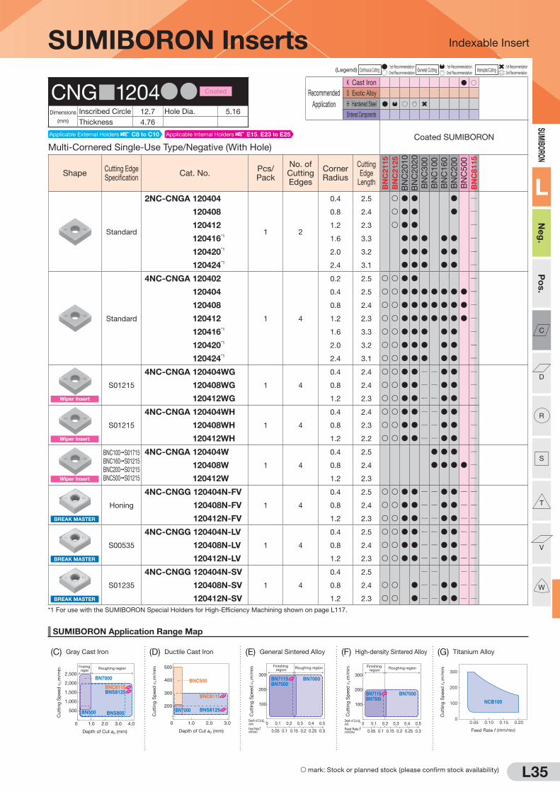
L35
SUMIBORON Application Range Map
(C) Gray Cast Iron (D) Ductile Cast Iron (E) General Sintered Alloy (F) High-density Sintered Alloy (G) Titanium Alloy
Indexable Insert
0 1.0 2.0 3.0
300
500
200
400
Depth of Cut ap (mm)
BNC500
BNC8115
BNS8125BN7000
Cutting
Speed
vc ( m
/min
)
100
200
300
Depth of Cut ap(mm)
Feed Rate f(mm/rev)
0 0.1
0.150.10.05 0.2 0.25 0.3
0.2 0.3 0.4 0.5
Finishing region
Roughing region
BN7500BN7115 BN7000
Cutting
Speed
vc ( m
/min
)
Depth of Cut ap(mm)
Feed Rate f(mm/rev)
0 0.1
0.150.10.05 0.2 0.25 0.3
0.2 0.3 0.4 0.5
100
200
300
Finishing region
Roughing region
BN7500BN7115 BN7000
Cutting
Speed
vc ( m
/min
)
0
100
200
300
0.05 0.10 0.15 0.20
Feed Rate f (mm/rev)
NCB100
Cutting
Speed
vc ( m
/min
)Finishing region
Roughing region
0 1.0 2.0 3.0 4.0
1,000
2,000
2,500
500
1,500
Depth of Cut ap (mm)
BNS800
BN7000
BN500
BNC8115BNS8125
Cutting
Speed
vc ( m
/min
)
SUM
IBORO
N
L
Ne
g.
Po
s.
C
D
R
S
T
V
W
(Legend) Continuous Cutting : 1st Recommendation
General Cutting : 1st Recommendation
Interrupted Cutting : 1st Recommendation
: 2nd Recommendation : 2nd Recommendation : 2nd Recommendation
Recommended
Application
K Cast Iron
S Exotic Alloy
H Hardened Steel
Sintered Components
SUMIBORON Inserts
Multi-Cornered Single-Use Type/Negative (With Hole)Coated SUMIBORON
ShapeCutting Edge Specification
Cat. No.Pcs/Pack
No. of Cutting Edges
Corner Radius
Cutting Edge
Length
BN
C2
11
5
BN
C2
12
5
BN
C2010
BN
C2020
BN
C300
BN
C100
BN
C160
BN
C200
BN
C500
BN
C8
11
5
Standard
2NC-CNGA 120404
1 2
0.4 2.5 S D D D Q
2NC-CNGA 120408 0.8 2.4 S D D D Q
2NC-CNGA 120412 1.2 2.3 S D D Q
2NC-CNGA 120416*1
1.6 3.3 D D D D D Q
2NC-CNGA 120420*1
2.0 3.2 D D D D D Q
2NC-CNGA 120424*1
2.4 3.1 D D D D D Q
Standard
4NC-CNGA 120402
1 4
0.2 2.5 S S D D Q
4NC-CNGA 120404 0.4 2.5 S S D D D D D D D Q
4NC-CNGA 120408 0.8 2.4 S S D D D D D D D Q
4NC-CNGA 120412 1.2 2.3 S S D D D D D D D Q
4NC-CNGA 120416*1
1.6 3.3 S S D D D D D Q
4NC-CNGA 120420*1
2.0 3.2 S S D D D D D Q
4NC-CNGA 120424*1
2.4 3.1 S S D D D D D Q
S01215
4NC-CNGA 120404WG
1 4
0.4 2.4 S S D D Q Q D D Q
4NC-CNGA 120408WG 0.8 2.4 S S D D Q Q D D Q
4NC-CNGA 120412WG 1.2 2.3 S S D D Q Q D D Q
S01215
4NC-CNGA 120404WH
1 4
0.4 2.4 S S D D Q Q D D Q
4NC-CNGA 120408WH 0.8 2.3 S S D D Q Q D D Q
4NC-CNGA 120412WH 1.2 2.2 S S D D Q Q D D Q
BNC100 S01715
BNC160 S01215
BNC200 S01215
BNC500 S01215
4NC-CNGA 120404W
1 4
0.4 2.5 D D D Q
4NC-CNGA 120408W 0.8 2.4 D D D D Q
4NC-CNGA 120412W 1.2 2.3 Q
Honing
4NC-CNGG 120404N-FV
1 4
0.4 2.5 S S D D Q Q D D Q Q
4NC-CNGG 120408N-FV 0.8 2.4 S S D D Q Q D D Q Q
4NC-CNGG 120412N-FV 1.2 2.3 S S D D Q Q D D Q Q
S00535
4NC-CNGG 120404N-LV
1 4
0.4 2.5 S S D D Q Q D D Q Q
4NC-CNGG 120408N-LV 0.8 2.4 S S D D Q Q D D Q Q
4NC-CNGG 120412N-LV 1.2 2.3 S S D D Q Q D D Q Q
S01235
4NC-CNGG 120404N-SV
1 4
0.4 2.5 Q Q Q Q
4NC-CNGG 120408N-SV 0.8 2.4 S S D Q Q D D Q Q
4NC-CNGG 120412N-SV 1.2 2.3 S S D Q Q D D Q Q*1 For use with the SUMIBORON Special Holders for High-Efficiency Machining shown on page L117.
Wiper Insert
Wiper Insert
Wiper Insert
BREAK MASTER
BREAK MASTER
BREAK MASTER
CNG 1204DD Coated
Dimensions
(mm)
Inscribed Circle 12.7 Hole Dia. 5.16
Thickness 4.76
S mark: Stock or planned stock (please confirm stock availability)
Applicable External Holders C8 to C10 Applicable Internal Holders E15, E23 to E25

(A) Hardened Steel (Uncoated SUMIBORON) (B) Hardened Steel (Coated SUMIBORON)
SUMIBORO
N
L
Neg.
Pos.
C
D
R
S
T
V
W
L36
SUMIBORON Application Range Map
Indexable Insert
300
200
100
0Heavy InterruptedContinuous Interrupted
BNX20
BN1000
BN350
BN2000
Cut
ting
Sp
eed
vc
( m/m
in) 300
200
100
0Heavy InterruptedContinuous Interrupted
BNC2010 BNC2020
BNC160
BNC100
BNC200
BNC2115 BNC2125
BNC300
Cut
ting
Sp
eed
vc
( m/m
in)
S mark: Stock or planned stock (please confirm stock availability)
BNX10 BNX20 BNX25BN1000BN2000 BN350
BNC2115BNC2125
BNC2010BNC2020
BNC100BNC160
BNC200BNC300
Neg.T01225 S01225 S01725 S01225
T01225S01225 S01225 S01225 S01225
Pos. T01235
BNC500 BN500BN7000BN700 BN7115 BN7500 BNC8115 BNS8125 BNS800 NCB100
Neg.S01215 T01215 T01215 T01215 T01215
S02020 T02020 T02020T01215
Pos. Q Q Q
(Legend) Continuous Cutting : 1st Recommendation
General Cutting : 1st Recommendation
Interrupted Cutting : 1st Recommendation
: 2nd Recommendation : 2nd Recommendation : 2nd Recommendation
Recommended
Application
K Cast Iron
S Exotic Alloy
H Hardened Steel
Sintered Components
SUMIBORON Inserts
Multi-Cornered Single-Use Type/Negative (With Hole)Coated SUMIBORON
ShapeCutting Edge Specification
Cat. No.Pcs/Pack
No. of Cutting Edges
Corner Radius
Cutting Edge
Length
BN
C2
11
5
BN
C2
12
5
BN
C2010
BN
C2020
BN
C300
BN
C100
BN
C160
BN
C200
BN
C500
BN
C8
11
5
Honing
2NC-CNGA 120404LE
1 2
0.4 2.5 Q Q D Q Q Q Q Q Q Q
2NC-CNGA 120408LE 0.8 2.4 Q Q D Q Q Q Q Q Q Q
2NC-CNGA 120412LE 1.2 2.3 Q Q D Q Q Q Q Q Q Q
Sharper Edge Type
T00515
2NC-CNGA 120402LT
1 2
0.2 2.5 Q Q Q D Q Q Q Q Q Q
2NC-CNGA 120404LT 0.4 2.5 Q Q Q D Q Q Q Q Q Q
2NC-CNGA 120408LT 0.8 2.4 Q Q Q D Q Q Q Q Q Q
2NC-CNGA 120412LT 1.2 2.3 Q Q Q D Q Q Q Q Q Q
Sharper Edge Type
BNC2115 S00515
BNC2125 S00515
BNC100 S01715
BNC160 S01020
BNC200 S01015
BNC300 S00515
2NC-CNGA 120402LS
1 2
0.2 2.5 S Q
2NC-CNGA 120404LS 0.4 2.5 S S D Q
2NC-CNGA 120408LS 0.8 2.4 S S D Q
2NC-CNGA 120412LS 1.2 2.3 S S D Q
Sharper Edge Type
BNC2115 S00515
BNC2125 S00515
BNC100 S01715
BNC160 S01020
BNC200 S01015
BNC300 S00515
4NC-CNGA 120404LS
1 4
0.4 2.5 D D D Q
4NC-CNGA 120408LS 0.8 2.4 D D D Q
4NC-CNGA 120412LS 1.2 2.3 D D D Q
BNC2115 S01730
BNC2125 S02735
BNC2010 S01730
BNC2020 S02735
BNC160 S01730
BNC200 S01735
BNC300 S01735
BNC500 S01225
4NC-CNGA 120404HS
1 4
0.4 2.5 S S D D D D D D Q
4NC-CNGA 120408HS 0.8 2.4 S S D D D D D D Q
4NC-CNGA 120412HS 1.2 2.3 S S D D D D D D Q
High-efficiency Type
S00535
4NC-CNGA 120404ES
1 4
0.4 2.5 D Q
4NC-CNGA 120408ES 0.8 2.4 D Q
4NC-CNGA 120412ES 1.2 2.3 D Q
Low Cutting Force
Strong Edge Type
C80° Diamond Type
CNG 1204DD Coated
Dimensions
(mm)
Inscribed Circle 12.7 Hole Dia. 5.16
Thickness 4.76
Applicable External Holders C8 to C10 Applicable Internal Holders E15, E23 to E25
Standard cutting edge specification Code Details L30, L31

SUMIBO
RON
L
Neg.
Pos.
C
D
R
S
T
V
W
L37
SUMIBORON Application Range Map
Indexable Insert
0 1.0 2.0 3.0
300
500
200
400
Depth of Cut ap (mm)
BNC500
BNC8115
BNS8125BN7000
Cut
ting
Sp
eed
vc
( m/m
in)
100
200
300
Depth of Cut ap(mm)
Feed Rate f(mm/rev)
0 0.1
0.150.10.05 0.2 0.25 0.3
0.2 0.3 0.4 0.5
Finishing region Roughing region
BN7500BN7115 BN7000
Cut
ting
Sp
eed
vc
( m/m
in)
Depth of Cut ap(mm)
Feed Rate f(mm/rev)
0 0.1
0.150.10.05 0.2 0.25 0.3
0.2 0.3 0.4 0.5
100
200
300
Finishing region Roughing region
BN7500BN7115 BN7000
Cut
ting
Sp
eed
vc
( m/m
in)
0
100
200
300
0.05 0.10 0.15 0.20
Feed Rate f (mm/rev)
NCB100
Cut
ting
Sp
eed
vc
( m/m
in)Finishing
region Roughing region
0 1.0 2.0 3.0 4.0
1,000
2,000
2,500
500
1,500
Depth of Cut ap (mm)
BNS800
BN7000
BN500
BNC8115BNS8125
Cut
ting
Sp
eed
vc
( m/m
in)
Recommended
Application
K Cast Iron
S Exotic Alloy
H Hardened Steel
Sintered Components
(C) Gray Cast Iron (D) Ductile Cast Iron (E) General Sintered Alloy (F) High-density Sintered Alloy (G) Titanium Alloy
(Legend) Continuous Cutting : 1st Recommendation
General Cutting : 1st Recommendation
Interrupted Cutting : 1st Recommendation
: 2nd Recommendation : 2nd Recommendation : 2nd Recommendation
Recommended
Application
K Cast Iron
S Exotic Alloy
H Hardened Steel
Sintered Components
SUMIBORON Inserts
Solid Type/Negative (Without Hole)Uncoated SUMIBORON
BIN
DE
RL
ES
S
SU
MIB
OR
ON
ShapeCutting Edge Specification
Cat. No. Pcs/PackNo. of Cutting Edges
Corner Radius
Cutting Edge
Length BN
X10
BN
X20
BN
X25
BN
1000
BN
2000
BN
350
BN
500
BN
7000
BN
700
BN
71
15
BN
7500
BN
S8125
BN
S800
NC
B100
Standard
CNGN 090308
1 Solid
0.8 9.5 Q Q Q Q Q Q Q Q Q Q Q D D Q
CNGN 090312 1.2 9.4 Q Q Q Q Q Q Q Q Q Q Q D D Q
Low Cutting Force
Sharp
Edge
CNGN 090308LF
1 Solid
0.8 9.5 Q Q Q Q Q Q Q Q Q Q Q D Q
CNGN 090312LF 1.2 9.4 Q Q Q Q Q Q Q Q Q Q Q D Q
C80° Diamond Type
CNGN0903DD Uncoated
Dimensions
(mm)
Inscribed Circle 9.525 Hole Dia. QThickness 3.18
Solid Type/Negative (Without Hole)Coated SUMIBORON
ShapeCutting Edge Specification
Cat. No. Pcs/PackNo. of Cutting Edges
Corner Radius
Cutting Edge
Length
BN
C2115
BN
C2
12
5
BN
C2010
BN
C2020
BN
C300
BN
C100
BN
C160
BN
C200
BN
C500
BN
C8
11
5
Standard
CNGN 090308
1 Solid
0.8 9.5 Q Q Q Q Q Q Q Q Q D
CNGN 090312 1.2 9.4 Q Q Q Q Q Q Q Q Q D
CNGN0903DD Coated
Dimensions
(mm)
Inscribed Circle 9.525 Hole Dia. QThickness 3.18
Applicable External Holders L113
Applicable External Holders L113

L38
SUMIBORON Application Range Map
Indexable Insert
300
200
100
0Heavy InterruptedContinuous Interrupted
BNX20
BN1000
BN350
BN2000
Cu
ttin
g S
peed
vc
( m/m
in) 300
200
100
0Heavy InterruptedContinuous Interrupted
BNC2010 BNC2020
BNC160
BNC100
BNC200
BNC2115 BNC2125
BNC300
Cu
ttin
g S
peed
vc
( m/m
in)
(A) Hardened Steel (Uncoated SUMIBORON) (B) Hardened Steel (Coated SUMIBORON)
SUMIBORO
N
L
Neg.
Pos.
C
D
R
S
T
V
W
BNX10 BNX20 BNX25BN1000BN2000 BN350
BNC2115BNC2125
BNC2010BNC2020
BNC100BNC160
BNC200BNC300
Neg.T01225 S01225 S01725 S01225
T01225S01225 S01225 S01225 S01225
Pos. T01235
BNC500 BN500BN7000BN700 BN7115 BN7500 BNC8115 BNS8125 BNS800 NCB100
Neg.S01215 T01215 T01215 T01215 T01215
S02020 T02020 T02020T01215
Pos. Q Q Q
(Legend) Continuous Cutting : 1st Recommendation
General Cutting : 1st Recommendation
Interrupted Cutting : 1st Recommendation
: 2nd Recommendation : 2nd Recommendation : 2nd Recommendation
Recommended
Application
K Cast Iron
S Exotic Alloy
H Hardened Steel
Sintered Components
Recommended
Application
K Cast Iron
S Exotic Alloy
H Hardened Steel
Sintered Components
Solid Type/Negative (Dimple Lock)Coated SUMIBORON
ShapeCutting Edge
SpecificationCat. No. Pcs/Pack
No. of
Cutting
Edges
Corner
Radius
Cutting
Edge
Length
BN
C2
11
5
BN
C2
12
5
BN
C2
01
0
BN
C2
02
0
BN
C3
00
BN
C1
00
BN
C1
60
BN
C2
00
BN
C5
00
BN
C8
11
5
Standard
CNGX 120412
1 Solid
1.2 12.6 Q Q Q Q Q Q Q Q Q DCNGX 120416 1.6 12.5 Q Q Q Q Q Q Q Q Q D
Solid Type/Negative (Without Hole)
ShapeCutting Edge
SpecificationCat. No. Pcs/Pack
No. of
Cutting
Edges
Corner
Radius
Cutting
Edge
Length
BN
C2
11
5
BN
C2
12
5
BN
C2
01
0
BN
C2
02
0
BN
C3
00
BN
C1
00
BN
C1
60
BN
C2
00
BN
C5
00
BN
C8
11
5
Standard
CNGN 120408
1 Solid
0.8 12.7 Q Q Q Q Q Q Q Q Q DCNGN 120412 1.2 12.6 Q Q Q Q Q Q Q Q Q DCNGN 120416 1.6 12.5 Q Q Q Q Q Q Q Q Q D
SUMIBORON Inserts
Solid Type/Negative (Dimple Lock)Uncoated SUMIBORON
BIN
DE
RLE
SS
S
UM
IBO
RO
N
ShapeCutting Edge
SpecificationCat. No. Pcs/Pack
No. of
Cutting
Edges
Corner
Radius
Cutting
Edge
Length BN
X1
0
BN
X2
0
BN
X2
5
BN
10
00
BN
20
00
BN
35
0
BN
50
0
BN
70
00
BN
70
0
BN
71
15
BN
75
00
BN
S8125
BN
S8
00
NC
B1
00
Standard
CNGX 120408
1 Solid
0.8 12.7 Q Q Q Q Q Q Q Q Q Q Q QCNGX 120412 1.2 12.6 Q Q Q Q Q Q Q Q Q Q Q D D QCNGX 120416 1.6 12.5 Q Q Q Q Q Q Q Q Q Q Q D D Q
C80° Diamond Type
CNG 1204DD Uncoated
Dimensions
(mm)
Inscribed Circle 12.7 Hole Dia. QThickness 4.76
Solid Type/Negative (Without Hole)
ShapeCutting Edge
SpecificationCat. No. Pcs/Pack
No. of
Cutting
Edges
Corner
Radius
Cutting
Edge
Length BN
X1
0
BN
X2
0
BN
X2
5
BN
10
00
BN
20
00
BN
35
0
BN
50
0
BN
70
00
BN
70
0
BN
71
15
BN
75
00
BN
S8125
BN
S8
00
NC
B1
00
Standard
CNGN 120408
1 Solid
0.8 12.7 Q Q Q Q Q Q Q Q Q Q Q D D QCNGN 120412 1.2 12.6 Q Q Q Q Q Q Q Q Q Q Q D D QCNGN 120416 1.6 12.5 Q Q Q Q Q Q Q Q Q Q Q D D Q
CNG 1204DD Coated
Dimensions
(mm)
Inscribed Circle 12.7 Hole Dia. QThickness 4.76
Standard cutting edge specification Code Details L30, L31
Applicable External Holders L113
Applicable External Holders L113

L39
SUMIBORON Application Range Map
(D) Ductile Cast Iron (G) Titanium Alloy
Indexable Insert
0 1.0 2.0 3.0
300
500
200
400
Depth of Cut ap (mm)
BNC500
BNC8115
BNS8125BN7000
Cutt
ing
Sp
eed
vc
( m/m
in)
100
200
300
Depth of Cut ap(mm)
Feed Rate f(mm/rev)
0 0.1
0.150.10.05 0.2 0.25 0.3
0.2 0.3 0.4 0.5
Finishing region
Roughing region
BN7500BN7115 BN7000
Cutt
ing
Sp
eed
vc
( m/m
in)
Depth of Cut ap(mm)
Feed Rate f(mm/rev)
0 0.1
0.150.10.05 0.2 0.25 0.3
0.2 0.3 0.4 0.5
100
200
300
Finishing region
Roughing region
BN7500BN7115 BN7000
Cutt
ing
Sp
eed
vc
( m/m
in)
0
100
200
300
0.05 0.10 0.15 0.20
Feed Rate f (mm/rev)
NCB100
Cutt
ing
Sp
eed
vc
( m/m
in)Finishing
regionRoughing region
0 1.0 2.0 3.0 4.0
1,000
2,000
2,500
500
1,500
Depth of Cut ap (mm)
BNS800
BN7000
BN500
BNC8115BNS8125
Cutt
ing
Sp
eed
vc
( m/m
in)
SUMIBO
RON
L
Neg.
Pos.
C
D
R
S
T
V
W
(C) Gray Cast Iron (E) General Sintered Alloy (F) High-density Sintered Alloy
Recommended
Application
K Cast Iron
S Exotic Alloy
H Hardened Steel
Sintered Components
(Legend) Continuous Cutting : 1st Recommendation
General Cutting : 1st Recommendation
Interrupted Cutting : 1st Recommendation
: 2nd Recommendation : 2nd Recommendation : 2nd Recommendation
Recommended
Application
K Cast Iron
S Exotic Alloy
H Hardened Steel
Sintered Components
SUMIBORON Inserts
Single-Use Type/7° Positive (With Hole)Uncoated SUMIBORON
BIN
DE
RLE
SS
S
UM
IBO
RO
N
ShapeCutting Edge
SpecificationCat. No. Pcs/Pack
No. of
Cutting
Edges
Corner
Radius
Cutting
Edge
Length BN
X1
0
BN
X2
0
BN
X2
5
BN
10
00
BN
20
00
BN
35
0
BN
50
0
BN
70
00
BN
70
0
BN
71
15
BN
75
00
BN
S8125
BN
S8
00
NC
B1
00
Low Cutting Force
Sharp
Edge
NU-CCEW 03X102LF
1 1
0.2 1.2 Q Q Q Q Q Q Q D D D Q Q
NU-CCEW 03X104LF 0.4 1.1 Q Q Q Q Q Q Q Q Q
Sharper Edge Type
T00715
NU-CCEW 03X102LT
1 1
0.2 1.2 Q D Q Q Q Q Q Q Q Q Q Q Q Q
NU-CCEW 03X104LT 0.4 1.1 Q D Q Q Q Q Q Q Q Q Q Q Q Q
*Depth of cut for single-use types is 0.5mm or less.
C80° Diamond Type
CCEW03X1DD Uncoated
Dimensions
(mm)
Inscribed Circle 3.5 Hole Dia. 1.9
Thickness 1.4
Single-Use Type/7° Positive (With Hole)Coated SUMIBORON
ShapeCutting Edge
SpecificationCat. No. Pcs/Pack
No. of
Cutting
Edges
Corner
Radius
Cutting
Edge
Length
BN
C2
11
5
BN
C2
12
5
BN
C2
01
0
BN
C2
02
0
BN
C3
00
BN
C1
00
BN
C1
60
BN
C2
00
BN
C5
00
BN
C8
11
5
Low Cutting Force
Honing
NC-CCEW 03X102LE
1 1
0.2 1.2 Q Q Q Q Q Q Q Q Q
NC-CCEW 03X104LE 0.4 1.1 Q Q Q Q Q Q Q Q Q
Sharper Edge Type
T00515
NC-CCEW 03X102LT
1 1
0.2 1.2 Q Q Q Q Q Q Q Q Q
NC-CCEW 03X104LT 0.4 1.1 Q Q Q Q Q Q Q Q Q
CCEW03X1DD Coated
Dimensions
(mm)
Inscribed Circle 3.5 Hole Dia. 1.9
Thickness 1.4
Applicable Internal Holders E18, E20
Applicable Internal Holders E18, E20

L40
SUMIBORON Application Range Map
(A) Hardened Steel (Uncoated SUMIBORON) (B) Hardened Steel (Coated SUMIBORON)
Indexable Insert
300
200
100
0Heavy InterruptedContinuous Interrupted
BNX20
BN1000
BN350
BN2000
Cut
ting
Sp
eed
vc
( m/m
in) 300
200
100
0Heavy InterruptedContinuous Interrupted
BNC2010 BNC2020
BNC160
BNC100
BNC200
BNC2115 BNC2125
BNC300
Cut
ting
Sp
eed
vc
( m/m
in)
SUMIBORO
N
L
Neg.
Pos.
C
D
R
S
T
V
W
Recommended
Application
K Cast Iron
S Exotic Alloy
H Hardened Steel
Sintered Components
BNX10 BNX20 BNX25BN1000BN2000 BN350
BNC2115BNC2125
BNC2010BNC2020
BNC100BNC160
BNC200BNC300
Neg.T01225 S01225 S01725 S01225
T01225S01225 S01225 S01225 S01225
Pos. T01235
BNC500 BN500BN7000BN700 BN7115 BN7500 BNC8115 BNS8125 BNS800 NCB100
Neg.S01215 T01215 T01215 T01215 T01215
S02020 T02020 T02020T01215
Pos. Q Q Q
(Legend) Continuous Cutting : 1st Recommendation
General Cutting : 1st Recommendation
Interrupted Cutting : 1st Recommendation
: 2nd Recommendation : 2nd Recommendation : 2nd Recommendation
Recommended
Application
K Cast Iron
S Exotic Alloy
H Hardened Steel
Sintered Components
SUMIBORON Inserts
Single-Use Type/7° Positive (With Hole)Uncoated SUMIBORON
BIN
DE
RL
ES
S
SU
MIB
OR
ON
ShapeCutting Edge Specification
Cat. No. Pcs/PackNo. of Cutting Edges
Corner Radius
Cutting Edge
Length BN
X10
BN
X20
BN
X25
BN
1000
BN
2000
BN
350
BN
500
BN
7000
BN
700
BN
71
15
BN
7500
BN
S8125
BN
S800
NC
B100
Low Cutting Force
Sharp
Edge
NU-CCEW 04X102LF
1 1
0.2 2.0 Q Q Q Q Q Q Q D Q Q
NU-CCEW 04X104LF 0.4 1.9 Q Q Q Q Q Q Q Q Q
Sharper Edge Type
T00715
NU-CCEW 04X102LT
1 1
0.2 2.0 Q D Q Q Q Q Q Q Q Q Q Q Q Q
NU-CCEW 04X104LT 0.4 1.9 Q D Q Q Q Q Q Q Q Q Q Q Q Q
*Depth of cut for single-use types is 0.5mm or less.
C80° Diamond Type
CCEW04X1DD Uncoated
Dimensions
(mm)
Inscribed Circle 4.3 Hole Dia. 2.3
Thickness 1.8
Single-Use Type/7° Positive (With Hole)Coated SUMIBORON
ShapeCutting Edge Specification
Cat. No. Pcs/PackNo. of Cutting Edges
Corner Radius
Cutting Edge
Length
BN
C2
11
5
BN
C2
12
5
BN
C2010
BN
C2020
BN
C300
BN
C100
BN
C160
BN
C200
BN
C500
BN
C8
11
5
Low Cutting Force
Honing
NC-CCEW 04X102LE
1 1
0.2 2.0 Q Q Q Q Q Q Q Q Q
NC-CCEW 04X104LE 0.4 1.9 Q Q Q Q Q Q Q Q Q
Sharper Edge Type
T00515
NC-CCEW 04X102LT
1 1
0.2 2.0 Q Q Q Q Q Q Q Q Q
NC-CCEW 04X104LT 0.4 1.9 Q Q Q Q Q Q Q Q Q
CCEW04X1DD Coated
Dimensions
(mm)
Inscribed Circle 4.3 Hole Dia. 2.3
Thickness 1.8
Standard cutting edge specification Code Details L30, L31
Applicable Internal Holders E18, E20
Applicable Internal Holders E18, E20

L41
SUMIBORON Application Range Map
(D) Ductile Cast Iron (G) Titanium Alloy
Indexable Insert
0 1.0 2.0 3.0
300
500
200
400
Depth of Cut ap (mm)
BNC500
BNC8115
BNS8125BN7000
Cut
ting
Sp
eed
vc
( m/m
in)
100
200
300
Depth of Cut ap(mm)
Feed Rate f(mm/rev)
0 0.1
0.150.10.05 0.2 0.25 0.3
0.2 0.3 0.4 0.5
Finishing region Roughing region
BN7500BN7115 BN7000
Cut
ting
Sp
eed
vc
( m/m
in)
Depth of Cut ap(mm)
Feed Rate f(mm/rev)
0 0.1
0.150.10.05 0.2 0.25 0.3
0.2 0.3 0.4 0.5
100
200
300
Finishing region Roughing region
BN7500BN7115 BN7000
Cut
ting
Sp
eed
vc
( m/m
in)
0
100
200
300
0.05 0.10 0.15 0.20
Feed Rate f (mm/rev)
NCB100
Cut
ting
Sp
eed
vc
( m/m
in)Finishing
region Roughing region
0 1.0 2.0 3.0 4.0
1,000
2,000
2,500
500
1,500
Depth of Cut ap (mm)
BNS800
BN7000
BN500
BNC8115BNS8125
Cut
ting
Sp
eed
vc
( m/m
in)
SUMIBO
RON
L
Neg.
Pos.
C
D
R
S
T
V
W
(C) Gray Cast Iron (E) General Sintered Alloy (F) High-density Sintered Alloy
(Legend) Continuous Cutting : 1st Recommendation
General Cutting : 1st Recommendation
Interrupted Cutting : 1st Recommendation
: 2nd Recommendation : 2nd Recommendation : 2nd Recommendation
Recommended
Application
K Cast Iron
S Exotic Alloy
H Hardened Steel
Sintered Components
Multi-Cornered Single-Use Type/7° Positive (With Hole)
ShapeCutting Edge Specification
Cat. No. Pcs/PackNo. of Cutting Edges
Corner Radius
Cutting Edge
Length BN
X10
BN
X20
BN
X25
BN
1000
BN
2000
BN
350
BN
500
BN
7000
BN
700
BN
71
15
BN
7500
BN
S8125
BN
S800
NC
B100
Standard
2NU-CCGW 060204
1 2
0.4 2.5 D D D Q Q
BREAK MASTER
Honing
2NU-CCGT 060204N-FV
1 2
0.4 2.3 Q Q Q Q D Q Q Q Q Q Q Q Q Q
*Use 2NS Type (2NS-CCGW) for BNX25. *Depth of cut for single-use types is 0.5mm or less.
SUMIBORON Inserts
Single-Use Type/7° Positive (With Hole)Uncoated SUMIBORON
BIN
DE
RL
ES
S
SU
MIB
OR
ON
ShapeCutting Edge Specification
Cat. No. Pcs/PackNo. of Cutting Edges
Corner Radius
Cutting Edge
Length BN
X10
BN
X20
BN
X25
BN
1000
BN
2000
BN
350
BN
500
BN
7000
BN
700
BN
71
15
BN
7500
BN
S8125
BN
S800
NC
B100
Standard
NU-CCGW 060202
1 1
0.2 2.5 D D Q Q
NU-CCGW 060204 0.4 2.5*1 D D D F Q Q D
NU-CCGW 060208 0.8 2.4 D Q Q
T-NU-CCGW 060202
10 1
0.2 2.5 D Q Q Q
T-NU-CCGW 060204 0.4 2.5 D Q Q Q
T-NU-CCGW 060208 0.8 2.4 Q Q Q
Sharper Edge Type
T01215
NU-CCGW 060202LT
1 1
0.2 2.5 Q Q Q Q D Q Q Q Q Q Q Q Q Q
NU-CCGW 060204LT 0.4 2.5 Q Q Q Q D Q Q Q Q Q Q Q Q Q
NU-CCGW 060208LT 0.8 2.4 Q Q Q Q D Q Q Q Q Q Q Q Q Q
Strong Edge Type
S01235
NU-CCGW 060202HS
1 1
0.2 2.5 Q Q Q Q D Q Q Q Q Q Q Q Q
NU-CCGW 060204HS 0.4 2.5 Q Q Q Q D Q Q Q Q Q Q Q Q
*Use NS Type (NS-CCGW) for BNX25. *Depth of cut for single-use types is 0.5mm or less.
*1 NCB100 cutting edge length is 2.3.
C80° Diamond Type
CCG 0602DD Uncoated
Dimensions
(mm)
Inscribed Circle 6.35 Hole Dia. 2.8
Thickness 2.38
Applicable Internal Holders E18 to E20Applicable External Holders C11, D13, D17, D22, D23
F mark: To be replaced by a new product, made to order, or discontinued (please confirm stock availability).
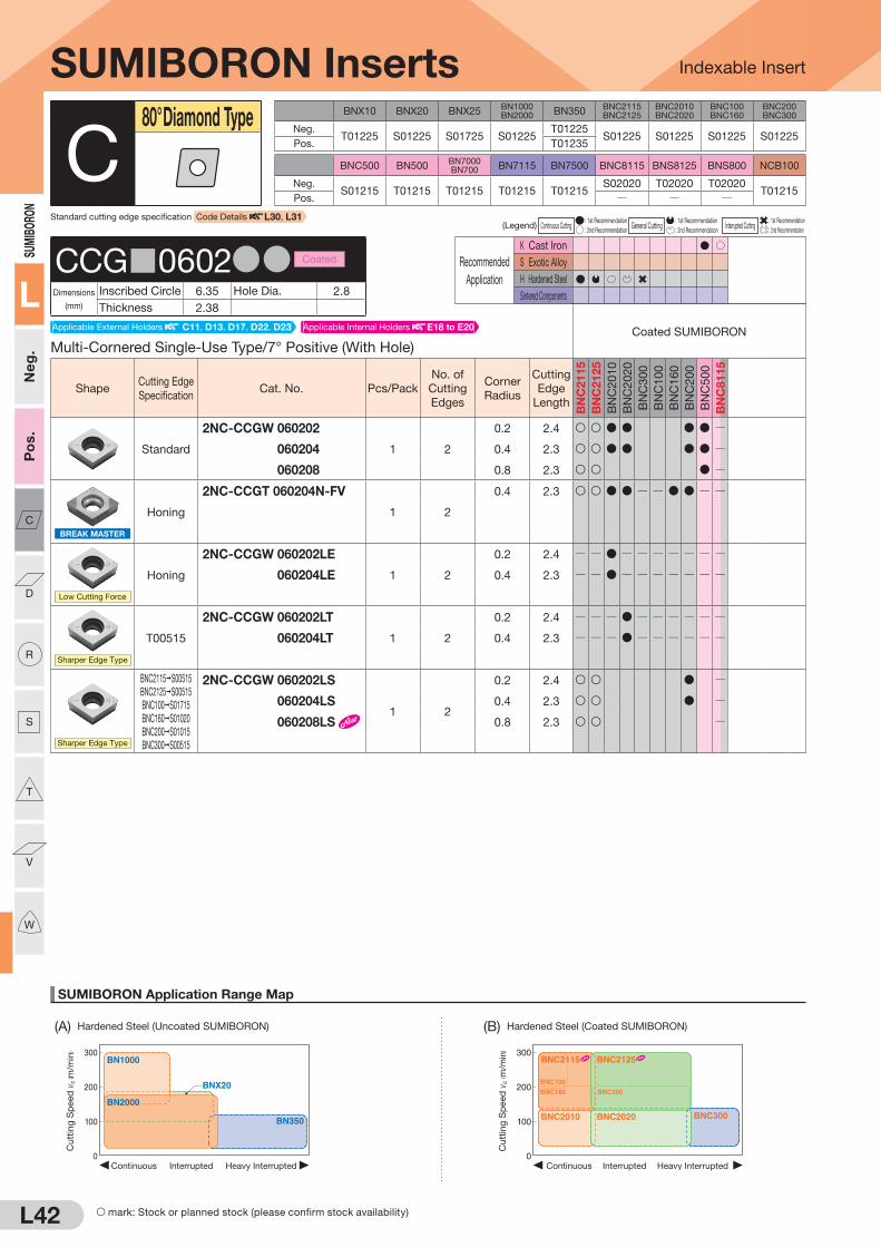
L42
SUMIBORON Application Range Map
Indexable Insert
300
200
100
0Heavy InterruptedContinuous Interrupted
BNX20
BN1000
BN350
BN2000
Cut
ting
Sp
eed
vc
( m/m
in) 300
200
100
0Heavy InterruptedContinuous Interrupted
BNC2010 BNC2020
BNC160
BNC100
BNC200
BNC2115 BNC2125
BNC300
Cut
ting
Sp
eed
vc
( m/m
in)
(A) Hardened Steel (Uncoated SUMIBORON) (B) Hardened Steel (Coated SUMIBORON)
SUMI
BORO
N
L
Neg
.P
os.
C
D
R
S
T
V
W
BNX10 BNX20 BNX25BN1000BN2000 BN350
BNC2115BNC2125
BNC2010BNC2020
BNC100BNC160
BNC200BNC300
Neg.T01225 S01225 S01725 S01225
T01225S01225 S01225 S01225 S01225
Pos. T01235
BNC500 BN500BN7000BN700 BN7115 BN7500 BNC8115 BNS8125 BNS800 NCB100
Neg.S01215 T01215 T01215 T01215 T01215
S02020 T02020 T02020T01215
Pos. Q Q Q
(Legend) Continuous Cutting : 1st Recommendation
General Cutting : 1st Recommendation
Interrupted Cutting : 1st Recommendation
: 2nd Recommendation : 2nd Recommendation : 2nd Recommendation
Recommended
Application
K Cast Iron
S Exotic Alloy
H Hardened Steel
Sintered Components
SUMIBORON Inserts
Multi-Cornered Single-Use Type/7° Positive (With Hole)Coated SUMIBORON
ShapeCutting Edge
SpecificationCat. No. Pcs/Pack
No. of
Cutting
Edges
Corner
Radius
Cutting
Edge
Length
BN
C2
11
5
BN
C2
12
5
BN
C2
01
0
BN
C2
02
0
BN
C3
00
BN
C1
00
BN
C1
60
BN
C2
00
BN
C5
00
BN
C8
11
5
Standard
2NC-CCGW 060202
1 2
0.2 2.4 S S D D D D Q
2NC-CCGW 060204 0.4 2.3 S S D D D D Q
2NC-CCGW 060208 0.8 2.3 S S D Q
BREAK MASTER
Honing
2NC-CCGT 060204N-FV
1 2
0.4 2.3 S S D D Q Q D D Q Q
Low Cutting Force
Honing
2NC-CCGW 060202LE
1 2
0.2 2.4 Q Q D Q Q Q Q Q Q Q
2NC-CCGW 060204LE 0.4 2.3 Q Q D Q Q Q Q Q Q Q
Sharper Edge Type
T00515
2NC-CCGW 060202LT
1 2
0.2 2.4 Q Q Q D Q Q Q Q Q Q
2NC-CCGW 060204LT 0.4 2.3 Q Q Q D Q Q Q Q Q Q
Sharper Edge Type
BNC2115 S00515
BNC2125 S00515
BNC100 S01715
BNC160 S01020
BNC200 S01015
BNC300 S00515
2NC-CCGW 060202LS
1 2
0.2 2.4 S S D Q
2NC-CCGW 060204LS 0.4 2.3 S S D Q
2NC-CCGW 060208LS 0.8 2.3 S S Q
C80° Diamond Type
CCG 0602DD Coated
Dimensions
(mm)
Inscribed Circle 6.35 Hole Dia. 2.8
Thickness 2.38
Applicable Internal Holders E18 to E20Applicable External Holders C11, D13, D17, D22, D23
Standard cutting edge specification Code Details L30, L31
S mark: Stock or planned stock (please confirm stock availability)

L43
SUMIBORON Application Range Map
(D) Ductile Cast Iron (G) Titanium Alloy
Indexable Insert
0 1.0 2.0 3.0
300
500
200
400
Depth of Cut ap (mm)
BNC500
BNC8115
BNS8125BN7000
Cut
ting
Sp
eed
vc
( m/m
in)
100
200
300
Depth of Cut ap(mm)
Feed Rate f(mm/rev)
0 0.1
0.150.10.05 0.2 0.25 0.3
0.2 0.3 0.4 0.5
Finishing region Roughing region
BN7500BN7115 BN7000
Cut
ting
Sp
eed
vc
( m/m
in)
Depth of Cut ap(mm)
Feed Rate f(mm/rev)
0 0.1
0.150.10.05 0.2 0.25 0.3
0.2 0.3 0.4 0.5
100
200
300
Finishing region Roughing region
BN7500BN7115 BN7000
Cut
ting
Sp
eed
vc
( m/m
in)
0
100
200
300
0.05 0.10 0.15 0.20
Feed Rate f (mm/rev)
NCB100
Cut
ting
Sp
eed
vc
( m/m
in)Finishing
region Roughing region
0 1.0 2.0 3.0 4.0
1,000
2,000
2,500
500
1,500
Depth of Cut ap (mm)
BNS800
BN7000
BN500
BNC8115BNS8125
Cut
ting
Sp
eed
vc
( m/m
in)
SUMIBORON
L
Neg
.P
os.
C
D
R
S
T
V
W
(C) Gray Cast Iron (E) General Sintered Alloy (F) High-density Sintered Alloy
(Legend) Continuous Cutting : 1st Recommendation
General Cutting : 1st Recommendation
Interrupted Cutting : 1st Recommendation
: 2nd Recommendation : 2nd Recommendation : 2nd Recommendation
Recommended
Application
K Cast Iron
S Exotic Alloy
H Hardened Steel
Sintered Components
SUMIBORON Inserts
Single-Use Type/7° Positive (With Hole)Uncoated SUMIBORON
BIN
DE
RLE
SS
S
UM
IBO
RO
N
ShapeCutting Edge
SpecificationCat. No. Pcs/Pack
No. of
Cutting
Edges
Corner
Radius
Cutting
Edge
Length BN
X1
0
BN
X2
0
BN
X2
5
BN
10
00
BN
20
00
BN
35
0
BN
50
0
BN
70
00
BN
70
0
BN
71
15
BN
75
00
BN
S8125
BN
S8
00
NC
B1
00
Standard
NU-CCGW 09T302
1 1
0.2 2.5 D D Q Q
NU-CCGW 09T304 0.4 2.5 D D D F Q Q D
NU-CCGW 09T308 0.8 2.4 D Q Q D
T-NU-CCGW 09T302
10 1
0.2 2.5 D Q Q Q
T-NU-CCGW 09T304 0.4 2.5 D Q Q Q
T-NU-CCGW 09T308 0.8 2.4 Q Q Q
Sharper Edge Type
T01215
NU-CCGW 09T302LT
1 1
0.2 2.5 Q Q Q Q D Q Q Q Q Q Q Q Q Q
NU-CCGW 09T304LT 0.4 2.5 Q Q Q Q D Q Q Q Q Q Q Q Q Q
NU-CCGW 09T308LT 0.8 2.4 Q Q Q Q D Q Q Q Q Q Q Q Q Q
Strong Edge Type
S01235
NU-CCGW 09T302HS
1 1
0.2 2.5 Q Q Q Q D Q Q Q Q Q Q Q Q
NU-CCGW 09T304HS 0.4 2.5 Q Q Q Q D Q Q Q Q Q Q Q Q
NU-CCGW 09T308HS 0.8 2.4 Q Q Q Q D Q Q Q Q Q Q Q Q
*Use NS Type (NS-CCGW) for BNX25. *Depth of cut for single-use types is 0.5mm or less.
C80° Diamond Type
CCG 09T3DD Uncoated
Dimensions
(mm)
Inscribed Circle 9.525 Hole Dia. 4.4
Thickness 3.97
Applicable External Holders C11, D13, D22, D23
F mark: To be replaced by a new product, made to order, or discontinued (please confirm stock availability).
Applicable Internal Holders E12, E18 to E20

L44
SUMIBORON Application Range Map
Indexable Insert
300
200
100
0Heavy InterruptedContinuous Interrupted
BNX20
BN1000
BN350
BN2000
Cu
ttin
g S
peed
vc
( m/m
in) 300
200
100
0Heavy InterruptedContinuous Interrupted
BNC2010 BNC2020
BNC160
BNC100
BNC200
BNC2115 BNC2125
BNC300
Cu
ttin
g S
peed
vc
( m/m
in)
(A) Hardened Steel (Uncoated SUMIBORON) (B) Hardened Steel (Coated SUMIBORON)
SUMI
BORO
N
L
Neg
.P
os.
C
D
R
S
T
V
W
Recommended
Application
K Cast Iron
S Exotic Alloy
H Hardened Steel
Sintered Components
S mark: Stock or planned stock (please confirm stock availability)
BNX10 BNX20 BNX25BN1000BN2000 BN350
BNC2115BNC2125
BNC2010BNC2020
BNC100BNC160
BNC200BNC300
Neg.T01225 S01225 S01725 S01225
T01225S01225 S01225 S01225 S01225
Pos. T01235
BNC500 BN500BN7000BN700 BN7115 BN7500 BNC8115 BNS8125 BNS800 NCB100
Neg.S01215 T01215 T01215 T01215 T01215
S02020 T02020 T02020T01215
Pos. Q Q Q
(Legend) Continuous Cutting : 1st Recommendation
General Cutting : 1st Recommendation
Interrupted Cutting : 1st Recommendation
: 2nd Recommendation : 2nd Recommendation : 2nd Recommendation
Recommended
Application
K Cast Iron
S Exotic Alloy
H Hardened Steel
Sintered Components
SUMIBORON Inserts
Multi-Cornered Single-Use Type/7° Positive (With Hole)Uncoated SUMIBORON
BIN
DE
RLE
SS
S
UM
IBO
RO
N
ShapeCutting Edge
SpecificationCat. No. Pcs/Pack
No. of
Cutting
Edges
Corner
Radius
Cutting
Edge
Length BN
X1
0
BN
X2
0
BN
X2
5
BN
10
00
BN
20
00
BN
35
0
BN
50
0
BN
70
00
BN
70
0
BN
71
15
BN
75
00
BN
S8125
BN
S8
00
NC
B1
00
Standard
2NU-CCGW 09T304
1 2
0.4 2.5 D D D Q Q
2NU-CCGW 09T308 0.8 2.4 D D D Q Q
Wiper Insert
S01215
2NU-CCGW 09T304WG
1 2
0.4 2.4 Q Q Q Q D Q Q Q Q Q Q Q Q
2NU-CCGW 09T308WG 0.8 2.4 Q Q Q Q D Q Q Q Q Q Q Q Q
Wiper Insert
S01215
2NU-CCGW 09T304WH
1 2
0.4 2.4 Q Q Q Q D Q Q Q Q Q Q Q Q
2NU-CCGW 09T308WH 0.8 2.3 Q Q Q Q D Q Q Q Q Q Q Q Q
BREAK MASTER
Honing
2NU-CCGT 09T304N-FV
1 2
0.4 2.4 Q Q Q Q D Q Q Q Q Q Q Q Q Q
2NU-CCGT 09T308N-FV 0.8 2.3 Q Q Q Q D Q Q Q Q Q Q Q Q Q
BREAK MASTER
S00535
2NU-CCGT 09T304N-LV
1 2
0.4 2.4 Q Q Q Q D Q Q Q Q Q Q Q Q Q
2NU-CCGT 09T308N-LV 0.8 2.3 Q Q Q Q D Q Q Q Q Q Q Q Q Q
*Use NS Type (NS-CCGW) for BNX25. *Depth of cut for single-use types is 0.5mm or less.
C80° Diamond Type
CCG 09T3DD Uncoated
Dimensions
(mm)
Inscribed Circle 9.525 Hole Dia. 4.4
Thickness 3.97
Multi-Cornered Single-Use Type/7° Positive (With Hole)Coated SUMIBORON
ShapeCutting Edge
SpecificationCat. No. Pcs/Pack
No. of
Cutting
Edges
Corner
Radius
Cutting
Edge
Length
BN
C2
11
5
BN
C2
12
5
BN
C2
01
0
BN
C2
02
0
BN
C3
00
BN
C1
00
BN
C1
60
BN
C2
00
BN
C5
00
BN
C8
11
5
Standard
2NC-CCGW 09T302
1 2
0.2 2.5 S S D D D D D Q
2NC-CCGW 09T304 0.4 2.5 S S D D D D D D D Q
2NC-CCGW 09T308 0.8 2.4 S S D D D D D D D Q
CCG 09T3DD Coated
Dimensions
(mm)
Inscribed Circle 9.525 Hole Dia. 4.4
Thickness 3.97
Applicable External Holders C11, D13, D17, D22, D23
Applicable External Holders C11, D13, D22, D23
Standard cutting edge specification Code Details L30, L31
Applicable Internal Holders E12, E18 to E20
Applicable Internal Holders E12, E18 to E20

L45
SUMIBORON Application Range Map
(D) Ductile Cast Iron (G) Titanium Alloy
Indexable Insert
0 1.0 2.0 3.0
300
500
200
400
Depth of Cut ap (mm)
BNC500
BNC8115
BNS8125BN7000
Cutt
ing
Sp
eed
vc
( m/m
in)
100
200
300
Depth of Cut ap(mm)
Feed Rate f(mm/rev)
0 0.1
0.150.10.05 0.2 0.25 0.3
0.2 0.3 0.4 0.5
Finishing region
Roughing region
BN7500BN7115 BN7000
Cutt
ing
Sp
eed
vc
( m/m
in)
Depth of Cut ap(mm)
Feed Rate f(mm/rev)
0 0.1
0.150.10.05 0.2 0.25 0.3
0.2 0.3 0.4 0.5
100
200
300
Finishing region
Roughing region
BN7500BN7115 BN7000
Cutt
ing
Sp
eed
vc
( m/m
in)
0
100
200
300
0.05 0.10 0.15 0.20
Feed Rate f (mm/rev)
NCB100
Cutt
ing
Sp
eed
vc
( m/m
in)Finishing
regionRoughing region
0 1.0 2.0 3.0 4.0
1,000
2,000
2,500
500
1,500
Depth of Cut ap (mm)
BNS800
BN7000
BN500
BNC8115BNS8125
Cutt
ing
Sp
eed
vc
( m/m
in)
SUMIBO
RON
L
Neg.
Pos.
C
D
R
S
T
V
W
(C) Gray Cast Iron (E) General Sintered Alloy (F) High-density Sintered Alloy
S mark: Stock or planned stock (please confirm stock availability)
(Legend) Continuous Cutting : 1st Recommendation
General Cutting : 1st Recommendation
Interrupted Cutting : 1st Recommendation
: 2nd Recommendation : 2nd Recommendation : 2nd Recommendation
Recommended
Application
K Cast Iron
S Exotic Alloy
H Hardened Steel
Sintered Components
SUMIBORON Inserts
Multi-Cornered Single-Use Type/7° Positive (With Hole)Coated SUMIBORON
ShapeCutting Edge
SpecificationCat. No. Pcs/Pack
No. of
Cutting
Edges
Corner
Radius
Cutting
Edge
Length
BN
C2
11
5
BN
C2
12
5
BN
C2
01
0
BN
C2
02
0
BN
C3
00
BN
C1
00
BN
C1
60
BN
C2
00
BN
C5
00
BN
C8
11
5
Wiper Insert
S01215
2NC-CCGW 09T304WG
1 2
0.4 2.4 S S D D Q Q D D Q
2NC-CCGW 09T308WG 0.8 2.4 S S D D Q Q D D Q
Wiper Insert
S01215
2NC-CCGW 09T304WH
1 2
0.4 2.4 S S D D Q Q D D Q
2NC-CCGW 09T308WH 0.8 2.3 S S D D Q Q D D Q
BREAK MASTER
Honing
2NC-CCGT 09T304N-FV
1 2
0.4 2.4 S S D D Q Q D D Q Q
2NC-CCGT 09T308N-FV 0.8 2.3 S S D D Q Q D D Q Q
BREAK MASTER
S00535
2NC-CCGT 09T304N-LV
1 2
0.4 2.4 S S D D Q Q D D Q Q
2NC-CCGT 09T308N-LV 0.8 2.3 S S D D Q Q D D Q Q
Low Cutting Force
Honing
2NC-CCGW 09T302LE
1 2
0.2 2.5 Q Q D Q Q Q Q Q Q Q
2NC-CCGW 09T304LE 0.4 2.5 Q Q D Q Q Q Q Q Q Q
2NC-CCGW 09T308LE 0.8 2.4 Q Q D Q Q Q Q Q Q Q
Sharper Edge Type
T00515
2NC-CCGW 09T302LT
1 2
0.2 2.5 Q Q Q D Q Q Q Q Q Q
2NC-CCGW 09T304LT 0.4 2.5 Q Q Q D Q Q Q Q Q Q
2NC-CCGW 09T308LT 0.8 2.4 Q Q Q D Q Q Q Q Q Q
Sharper Edge Type
BNC2115 S00515BNC2125 S00515BNC100 S01715BNC160 S01020BNC200 S01015BNC300 S00515
2NC-CCGW 09T302LS
1 2
0.2 2.5 S S D D Q
2NC-CCGW 09T304LS 0.4 2.5 S S D D D D Q
2NC-CCGW 09T308LS 0.8 2.4 S S D D D D Q
BNC2115 S01730BNC2125 S02735BNC2010 S01730BNC2020 S02735BNC160 S01730BNC200 S01735BNC300 S01735BNC500 S01225
2NC-CCGW 09T304HS
1 2
0.4 2.5 D Q
2NC-CCGW 09T308HS 0.8 2.4 D Q
Strong Edge Type
C80° Diamond Type
CCG 09T3DD Coated
Dimensions
(mm)
Inscribed Circle 9.525 Hole Dia. 4.4
Thickness 3.97
Applicable External Holders C11, D13, D17, D22, D23 Applicable Internal Holders E12, E18 to E20

L46
SUMIBORON Application Range Map
Indexable Insert
300
200
100
0Heavy InterruptedContinuous Interrupted
BNX20
BN1000
BN350
BN2000
Cu
ttin
g S
peed
vc
( m/m
in) 300
200
100
0Heavy InterruptedContinuous Interrupted
BNC2010 BNC2020
BNC160
BNC100
BNC200
BNC2115 BNC2125
BNC300
Cu
ttin
g S
peed
vc
( m/m
in)
(A) Hardened Steel (Uncoated SUMIBORON) (B) Hardened Steel (Coated SUMIBORON)
SUMIBORO
N
L
Neg.
Pos.
C
D
R
S
T
V
W
BNX10 BNX20 BNX25BN1000BN2000 BN350
BNC2115BNC2125
BNC2010BNC2020
BNC100BNC160
BNC200BNC300
Neg.T01225 S01225 S01725 S01225
T01225S01225 S01225 S01225 S01225
Pos. T01235
BNC500 BN500BN7000BN700 BN7115 BN7500 BNC8115 BNS8125 BNS800 NCB100
Neg.S01215 T01215 T01215 T01215 T01215
S02020 T02020 T02020T01215
Pos. Q Q Q
(Legend) Continuous Cutting : 1st Recommendation
General Cutting : 1st Recommendation
Interrupted Cutting : 1st Recommendation
: 2nd Recommendation : 2nd Recommendation : 2nd Recommendation
Recommended
Application
K Cast Iron
S Exotic Alloy
H Hardened Steel
Sintered Components
SUMIBORON Inserts
Single-Use Type/7° Positive (Without Hole)Uncoated SUMIBORON
BIN
DE
RLE
SS
S
UM
IBO
RO
N
ShapeCutting Edge
SpecificationCat. No. Pcs/Pack
No. of
Cutting
Edges
Corner
Radius
Cutting
Edge
Length BN
X1
0
BN
X2
0
BN
X2
5
BN
10
00
BN
20
00
BN
35
0
BN
50
0
BN
70
00
BN
70
0
BN
71
15
BN
75
00
BN
S8125
BN
S8
00
NC
B1
00
Standard
NU-CCGN 040104
1 1
0.4 2.5 D Q Q
NU-CCGN 040108 0.8 2.4 D Q Q
T-NU-CCGN 040104
10 1
0.4 2.5 D Q Q Q
T-NU-CCGN 040108 0.8 2.4 D Q Q Q
Strong Edge Type
S01235
NU-CCGN 040104HS
1 1
0.4 2.5 Q Q Q Q D Q Q Q Q Q Q Q Q
NU-CCGN 040108HS 0.8 2.4 Q Q Q Q D Q Q Q Q Q Q Q Q
*Use NS Type (NS-CCGN) for BNX25. *Depth of cut for single-use types is 0.5mm or less.
C80° Diamond Type
CCGN0401DD Uncoated
Dimensions
(mm)
Inscribed Circle 4.76 Hole Dia. QThickness 1.59
Standard cutting edge specification Code Details L30, L31
Applicable Holder: Special Holder

L47
SUMIBORON Application Range Map
(D) Ductile Cast Iron (G) Titanium Alloy
Indexable Insert
0 1.0 2.0 3.0
300
500
200
400
Depth of Cut ap (mm)
BNC500
BNC8115
BNS8125BN7000
Cutt
ing
Sp
eed
vc
( m/m
in)
100
200
300
Depth of Cut ap(mm)
Feed Rate f(mm/rev)
0 0.1
0.150.10.05 0.2 0.25 0.3
0.2 0.3 0.4 0.5
Finishing region
Roughing region
BN7500BN7115 BN7000
Cutt
ing
Sp
eed
vc
( m/m
in)
Depth of Cut ap(mm)
Feed Rate f(mm/rev)
0 0.1
0.150.10.05 0.2 0.25 0.3
0.2 0.3 0.4 0.5
100
200
300
Finishing region
Roughing region
BN7500BN7115 BN7000
Cutt
ing
Sp
eed
vc
( m/m
in)
0
100
200
300
0.05 0.10 0.15 0.20
Feed Rate f (mm/rev)
NCB100
Cutt
ing
Sp
eed
vc
( m/m
in)Finishing
regionRoughing region
0 1.0 2.0 3.0 4.0
1,000
2,000
2,500
500
1,500
Depth of Cut ap (mm)
BNS800
BN7000
BN500
BNC8115BNS8125
Cutt
ing
Sp
eed
vc
( m/m
in)
SUMIBO
RON
L
Neg.
Pos.
C
D
R
S
T
V
W
(C) Gray Cast Iron (E) General Sintered Alloy (F) High-density Sintered Alloy
Recommended
Application
K Cast Iron
S Exotic Alloy
H Hardened Steel
Sintered Components
(Legend) Continuous Cutting : 1st Recommendation
General Cutting : 1st Recommendation
Interrupted Cutting : 1st Recommendation
: 2nd Recommendation : 2nd Recommendation : 2nd Recommendation
Recommended
Application
K Cast Iron
S Exotic Alloy
H Hardened Steel
Sintered Components
SUMIBORON Inserts
Single-Use Type/11° Positive (With Hole)Uncoated SUMIBORON
BIN
DE
RLE
SS
S
UM
IBO
RO
N
ShapeCutting Edge
SpecificationCat. No. Pcs/Pack
No. of
Cutting
Edges
Corner
Radius
Cutting
Edge
Length BN
X1
0
BN
X2
0
BN
X2
5
BN
10
00
BN
20
00
BN
35
0
BN
50
0
BN
70
00
BN
70
0
BN
71
15
BN
75
00
BN
S8125
BN
S8
00
NC
B1
00
Standard
NU-CPGW 080202
1 1
0.2 2.5 D Q Q
NU-CPGW 080204 0.4 2.5 D D Q Q
NU-CPGW 080208 0.8 2.4 D Q Q
Sharper Edge Type
T01215
NU-CPGW 080204LT
1 1
0.4 2.5 Q Q Q Q D Q Q Q Q Q Q Q Q Q
Strong Edge Type
S01235
NU-CPGW 080202HS
1 1
0.2 2.5 Q Q Q Q D Q Q Q Q Q Q Q Q
NU-CPGW 080204HS 0.4 2.5 Q Q Q Q D Q Q Q Q Q Q Q Q
NU-CPGW 080208HS 0.8 2.4 Q Q Q Q D Q Q Q Q Q Q Q Q
*Use NS Type (NS-CPGW) for BNX25. *Depth of cut for single-use types is 0.5mm or less.
C80° Diamond Type
CPGW0802DD Uncoated
Dimensions
(mm)
Inscribed Circle 7.94 Hole Dia. 3.4
Thickness 2.38
Multi-Cornered Single-Use Type/11° Positive (With Hole)Coated SUMIBORON
ShapeCutting Edge
SpecificationCat. No. Pcs/Pack
No. of
Cutting
Edges
Corner
Radius
Cutting
Edge
Length
BN
C2
11
5
BN
C2
12
5
BN
C2
01
0
BN
C2
02
0
BN
C3
00
BN
C1
00
BN
C1
60
BN
C2
00
BN
C5
00
BN
C8
11
5
Standard
2NC-CPGW 080202
1 2
0.2 2.5 D D Q
2NC-CPGW 080204 0.4 2.5 D D Q
CPGW0802DD Coated
Dimensions
(mm)
Inscribed Circle 7.94 Hole Dia. 3.4
Thickness 2.38
Applicable Internal Holders E21, E22
Applicable Internal Holders E21, E22

L48
SUMIBORON Application Range Map
Indexable Insert
300
200
100
0Heavy InterruptedContinuous Interrupted
BNX20
BN1000
BN350
BN2000
Cu
ttin
g S
peed
vc
( m/m
in) 300
200
100
0Heavy InterruptedContinuous Interrupted
BNC2010 BNC2020
BNC160
BNC100
BNC200
BNC2115 BNC2125
BNC300
Cu
ttin
g S
peed
vc
( m/m
in)
(A) Hardened Steel (Uncoated SUMIBORON) (B) Hardened Steel (Coated SUMIBORON)
SUMIBORO
N
L
Neg.
Pos.
C
D
R
S
T
V
W
Recommended
Application
K Cast Iron
S Exotic Alloy
H Hardened Steel
Sintered Components
BNX10 BNX20 BNX25BN1000BN2000 BN350
BNC2115BNC2125
BNC2010BNC2020
BNC100BNC160
BNC200BNC300
Neg.T01225 S01225 S01725 S01225
T01225S01225 S01225 S01225 S01225
Pos. T01235
BNC500 BN500BN7000BN700 BN7115 BN7500 BNC8115 BNS8125 BNS800 NCB100
Neg.S01215 T01215 T01215 T01215 T01215
S02020 T02020 T02020T01215
Pos. Q Q Q
(Legend) Continuous Cutting : 1st Recommendation
General Cutting : 1st Recommendation
Interrupted Cutting : 1st Recommendation
: 2nd Recommendation : 2nd Recommendation : 2nd Recommendation
Recommended
Application
K Cast Iron
S Exotic Alloy
H Hardened Steel
Sintered Components
SUMIBORON Inserts
Single-Use Type/11° Positive (With Hole)Uncoated SUMIBORON
BIN
DE
RLE
SS
S
UM
IBO
RO
N
ShapeCutting Edge
SpecificationCat. No. Pcs/Pack
No. of
Cutting
Edges
Corner
Radius
Cutting
Edge
Length BN
X1
0
BN
X2
0
BN
X2
5
BN
10
00
BN
20
00
BN
35
0
BN
50
0
BN
70
00
BN
70
0
BN
71
15
BN
75
00
BN
S8125
BN
S8
00
NC
B1
00
Standard
NU-CPGW 090302
1 1
0.2 2.5 D D Q Q
NU-CPGW 090304 0.4 2.5 D D Q Q
NU-CPGW 090308 0.8 2.4 D D Q Q
Sharper Edge Type
T01215
NU-CPGW 090302LT
1 1
0.2 2.5 Q Q Q Q D Q Q Q Q Q Q Q Q Q
NU-CPGW 090304LT 0.4 2.5 Q Q Q Q D Q Q Q Q Q Q Q Q Q
NU-CPGW 090308LT 0.8 2.4 Q Q Q Q D Q Q Q Q Q Q Q Q Q
Strong Edge Type
S01235
NU-CPGW 090302HS
1 1
0.2 2.5 Q Q Q Q D Q Q Q Q Q Q Q Q
NU-CPGW 090304HS 0.4 2.5 Q Q Q Q D Q Q Q Q Q Q Q Q
NU-CPGW 090308HS 0.8 2.4 Q Q Q Q D Q Q Q Q Q Q Q Q
*Use NS Type (NS-CPGW) for BNX25. *Depth of cut for single-use types is 0.5mm or less.
C80° Diamond Type
CPGW0903DD Uncoated
Dimensions
(mm)
Inscribed Circle 9.525 Hole Dia. 4.4
Thickness 3.18
Multi-Cornered Single-Use Type/11° Positive (With Hole)Coated SUMIBORON
ShapeCutting Edge
SpecificationCat. No. Pcs/Pack
No. of
Cutting
Edges
Corner
Radius
Cutting
Edge
Length
BN
C2
11
5
BN
C2
12
5
BN
C2
01
0
BN
C2
02
0
BN
C3
00
BN
C1
00
BN
C1
60
BN
C2
00
BN
C5
00
BN
C8
11
5
Standard
2NC-CPGW 090302
1 2
0.2 2.5 D D Q
2NC-CPGW 090304 0.4 2.5 D D Q
CPGW0903DD Coated
Dimensions
(mm)
Inscribed Circle 9.525 Hole Dia. 4.4
Thickness 3.18
Applicable Internal Holders E12, E21, E22
Applicable Internal Holders E12, E21, E22
Standard cutting edge specification Code Details L30, L31

L49
SUMIBORON Application Range Map
(D) Ductile Cast Iron (G) Titanium Alloy
Indexable Insert
0 1.0 2.0 3.0
300
500
200
400
Depth of Cut ap (mm)
BNC500
BNC8115
BNS8125BN7000
Cutt
ing
Sp
eed
vc
( m/m
in)
100
200
300
Depth of Cut ap(mm)
Feed Rate f(mm/rev)
0 0.1
0.150.10.05 0.2 0.25 0.3
0.2 0.3 0.4 0.5
Finishing region
Roughing region
BN7500BN7115 BN7000
Cutt
ing
Sp
eed
vc
( m/m
in)
Depth of Cut ap(mm)
Feed Rate f(mm/rev)
0 0.1
0.150.10.05 0.2 0.25 0.3
0.2 0.3 0.4 0.5
100
200
300
Finishing region
Roughing region
BN7500BN7115 BN7000
Cutt
ing
Sp
eed
vc
( m/m
in)
0
100
200
300
0.05 0.10 0.15 0.20
Feed Rate f (mm/rev)
NCB100
Cutt
ing
Sp
eed
vc
( m/m
in)Finishing
regionRoughing region
0 1.0 2.0 3.0 4.0
1,000
2,000
2,500
500
1,500
Depth of Cut ap (mm)
BNS800
BN7000
BN500
BNC8115BNS8125
Cutt
ing
Sp
eed
vc
( m/m
in)
SUMIBO
RON
L
Neg.
Pos.
C
D
R
S
T
V
W
(C) Gray Cast Iron (E) General Sintered Alloy (F) High-density Sintered Alloy
(Legend) Continuous Cutting : 1st Recommendation
General Cutting : 1st Recommendation
Interrupted Cutting : 1st Recommendation
: 2nd Recommendation : 2nd Recommendation : 2nd Recommendation
Recommended
Application
K Cast Iron
S Exotic Alloy
H Hardened Steel
Sintered Components
Recommended
Application
K Cast Iron
S Exotic Alloy
H Hardened Steel
Sintered Components
SUMIBORON Inserts
Multi-Cornered Single-Use Type/Negative (With Hole)Coated SUMIBORON
ShapeCutting Edge
SpecificationCat. No. Pcs/Pack
No. of
Cutting
Edges
Corner
Radius
Cutting
Edge
Length
BN
C2
11
5
BN
C2
12
5
BN
C2
01
0
BN
C2
02
0
BN
C3
00
BN
C1
00
BN
C1
60
BN
C2
00
BN
C5
00
BN
C8
11
5
Standard
2NC-DNGA 110404
1 2
0.4 2.5 S S D D Q2NC-DNGA 110408 0.8 2.1 S S D D Q2NC-DNGA 110412 1.2 2.0 S S D D Q
D55° Diamond Type
DNGA1104DD Coated
Dimensions
(mm)
Inscribed Circle 9.525 Hole Dia. 3.81
Thickness 4.76
Single-Use Type/Negative (With Hole)Uncoated SUMIBORON
BIN
DE
RLE
SS
S
UM
IBO
RO
N
ShapeCutting Edge
SpecificationCat. No. Pcs/Pack
No. of
Cutting
Edges
Corner
Radius
Cutting
Edge
Length BN
X1
0
BN
X2
0
BN
X2
5
BN
10
00
BN
20
00
BN
35
0
BN
50
0
BN
70
00
BN
70
0
BN
71
15
BN
75
00
BN
S8125
BN
S8
00
NC
B1
00
Standard
NU-DNMA 150401
1 1
0.1 2.7 Q D Q Q QNU-DNMA 150402 0.2 2.5 Q D Q Q QNU-DNMA 150404 0.4 2.5 D D Q D D D D D F Q Q QNU-DNMA 150408 0.8 2.1 D D Q D D D D D F Q Q QNU-DNMA 150412 1.2 2.0 Q D D D F Q Q QT-NU-DNMA 150401
10 1
0.1 2.7 Q Q Q QT-NU-DNMA 150402 0.2 2.5 Q Q Q QT-NU-DNMA 150404 0.4 2.5 D D Q D D D D Q Q QT-NU-DNMA 150408 0.8 2.1 D D Q D D D D Q Q QT-NU-DNMA 150412 1.2 2.0 Q D Q Q Q
Standard
NS-DNMA 150404
1 1
0.4 2.5 Q Q F Q Q Q Q Q Q Q Q Q Q QNS-DNMA 150408 0.8 2.1 Q Q F Q Q Q Q Q Q Q Q Q Q QNS-DNMA 150412 1.2 2.0 Q Q Q Q Q Q Q Q Q Q Q Q QT-NS-DNMA 150404
10 1
0.4 2.5 Q Q F Q Q Q Q Q Q Q Q Q Q QT-NS-DNMA 150408 0.8 2.1 Q Q F Q Q Q Q Q Q Q Q Q Q QT-NS-DNMA 150412 1.2 2.0 Q Q Q Q Q Q Q Q Q Q Q Q Q
Standard
NU-DNGA 150404
1 1
0.4 2.5 Q Q Q Q Q Q Q Q Q Q Q Q Q DNU-DNGA 150408 0.8 2.1 Q Q Q Q Q Q Q Q Q Q Q Q Q DNU-DNGA 150412 1.2 2.0 Q Q Q Q Q Q Q Q Q Q Q Q Q D
*Depth of cut for single-use types is 0.5mm or less.
DN 1504DD Uncoated
Dimensions
(mm)
Inscribed Circle 12.7 Hole Dia. 5.16
Thickness 4.76
Applicable Internal Holders E34, E35Applicable External Holders C14
Applicable Internal Holders E15, E33 to E35Applicable External Holders C12 to C14
S mark: Stock or planned stock item (please confirm stock availability) F: To be replaced by new item (please confirm stock availability)

L50
SUMIBORON Application Range Map
Indexable Insert
300
200
100
0Heavy InterruptedContinuous Interrupted
BNX20
BN1000
BN350
BN2000
Cu
ttin
g S
peed
vc
( m/m
in) 300
200
100
0Heavy InterruptedContinuous Interrupted
BNC2010 BNC2020
BNC160
BNC100
BNC200
BNC2115 BNC2125
BNC300
Cu
ttin
g S
peed
vc
( m/m
in)
(A) Hardened Steel (Uncoated SUMIBORON) (B) Hardened Steel (Coated SUMIBORON)
SUMIBORO
N
L
Neg.
Pos.
C
D
R
S
T
V
W
BNX10 BNX20 BNX25BN1000BN2000 BN350
BNC2115BNC2125
BNC2010BNC2020
BNC100BNC160
BNC200BNC300
Neg.T01225 S01225 S01725 S01225
T01225S01225 S01225 S01225 S01225
Pos. T01235
BNC500 BN500BN7000BN700 BN7115 BN7500 BNC8115 BNS8125 BNS800 NCB100
Neg.S01215 T01215 T01215 T01215 T01215
S02020 T02020 T02020T01215
Pos. Q Q Q
(Legend) Continuous Cutting : 1st Recommendation
General Cutting : 1st Recommendation
Interrupted Cutting : 1st Recommendation
: 2nd Recommendation : 2nd Recommendation : 2nd Recommendation
Recommended
Application
K Cast Iron
S Exotic Alloy
H Hardened Steel
Sintered Components
SUMIBORON Inserts
Multi-Cornered Single-Use Type/Negative (With Hole)Uncoated SUMIBORON
BIN
DE
RLE
SS
S
UM
IBO
RO
N
ShapeCutting Edge
SpecificationCat. No. Pcs/Pack
No. of
Cutting
Edges
Corner
Radius
Cutting
Edge
Length BN
X1
0
BN
X2
0
BN
X2
5
BN
10
00
BN
20
00
BN
35
0
BN
50
0
BN
70
00
BN
70
0
BN
71
15
BN
75
00
BN
S8125
BN
S8
00
NC
B1
00
Standard
2NU-DNGA 150404
1 2
0.4 2.5 D Q D D D D F D D Q Q
2NU-DNGA 150408 0.8 2.1 D Q D D D D F D D Q Q
2NU-DNGA 150412 1.2 2.0 Q D D Q Q
T-2NU-DNGA 150404
10 2
0.4 2.5 D Q D Q Q Q
T-2NU-DNGA 150408 0.8 2.1 D Q D D D F Q Q Q
T-2NU-DNGA 150412 1.2 2.0 Q Q Q Q
Standard
2NS-DNGA 150404
1 2
0.4 2.5 Q Q F Q Q Q Q Q Q Q Q Q Q Q
2NS-DNGA 150408 0.8 2.1 Q Q F Q Q Q Q Q Q Q Q Q Q Q
2NS-DNGA 150412 1.2 2.0 Q Q Q Q Q Q Q Q Q Q Q Q Q
T-2NS-DNGA 150404
10 2
0.4 2.5 Q Q F Q Q Q Q Q Q Q Q Q Q Q
T-2NS-DNGA 150408 0.8 2.1 Q Q F Q Q Q Q Q Q Q Q Q Q Q
T-2NS-DNGA 150412 1.2 2.0 Q Q Q Q Q Q Q Q Q Q Q Q Q*Depth of cut for single-use types is 0.5mm or less.
D55° Diamond Type
DN 1504DD Uncoated
Dimensions
(mm)
Inscribed Circle 12.7 Hole Dia. 5.16
Thickness 4.76
Standard cutting edge specification Code Details L30, L31
F mark: To be replaced by a new product, made to order, or discontinued (please confirm stock availability).
Applicable Internal Holders E15, E33 to E35Applicable External Holders C12 to C14
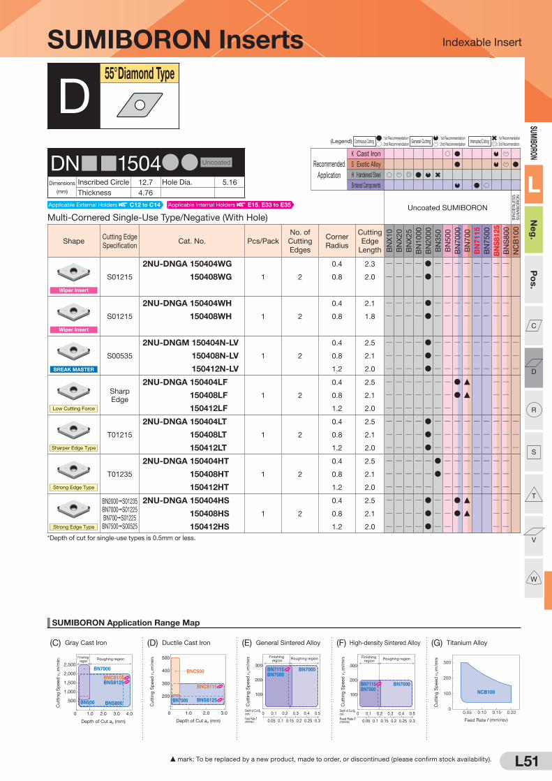
L51
SUMIBORON Application Range Map
(D) Ductile Cast Iron (G) Titanium Alloy
Indexable Insert
0 1.0 2.0 3.0
300
500
200
400
Depth of Cut ap (mm)
BNC500
BNC8115
BNS8125BN7000
Cutt
ing
Sp
eed
vc
( m/m
in)
100
200
300
Depth of Cut ap(mm)
Feed Rate f(mm/rev)
0 0.1
0.150.10.05 0.2 0.25 0.3
0.2 0.3 0.4 0.5
Finishing region
Roughing region
BN7500BN7115 BN7000
Cutt
ing
Sp
eed
vc
( m/m
in)
Depth of Cut ap(mm)
Feed Rate f(mm/rev)
0 0.1
0.150.10.05 0.2 0.25 0.3
0.2 0.3 0.4 0.5
100
200
300
Finishing region
Roughing region
BN7500BN7115 BN7000
Cutt
ing
Sp
eed
vc
( m/m
in)
0
100
200
300
0.05 0.10 0.15 0.20
Feed Rate f (mm/rev)
NCB100
Cutt
ing
Sp
eed
vc
( m/m
in)Finishing
regionRoughing region
0 1.0 2.0 3.0 4.0
1,000
2,000
2,500
500
1,500
Depth of Cut ap (mm)
BNS800
BN7000
BN500
BNC8115BNS8125
Cutt
ing
Sp
eed
vc
( m/m
in)
SUMIBO
RON
L
Neg.
Pos.
C
D
R
S
T
V
W
(C) Gray Cast Iron (E) General Sintered Alloy (F) High-density Sintered Alloy
(Legend) Continuous Cutting : 1st Recommendation
General Cutting : 1st Recommendation
Interrupted Cutting : 1st Recommendation
: 2nd Recommendation : 2nd Recommendation : 2nd Recommendation
Recommended
Application
K Cast Iron
S Exotic Alloy
H Hardened Steel
Sintered Components
SUMIBORON Inserts
Multi-Cornered Single-Use Type/Negative (With Hole)Uncoated SUMIBORON
BIN
DE
RLE
SS
S
UM
IBO
RO
N
ShapeCutting Edge
SpecificationCat. No. Pcs/Pack
No. of
Cutting
Edges
Corner
Radius
Cutting
Edge
Length BN
X1
0
BN
X2
0
BN
X2
5
BN
10
00
BN
20
00
BN
35
0
BN
50
0
BN
70
00
BN
70
0
BN
71
15
BN
75
00
BN
S8125
BN
S8
00
NC
B1
00
Wiper Insert
S01215
2NU-DNGA 150404WG
1 2
0.4 2.3 Q Q Q Q D Q Q Q Q Q Q Q Q
2NU-DNGA 150408WG 0.8 2.0 Q Q Q Q D Q Q Q Q Q Q Q Q
Wiper Insert
S01215
2NU-DNGA 150404WH
1 2
0.4 2.1 Q Q Q Q D Q Q Q Q Q Q Q Q
2NU-DNGA 150408WH 0.8 1.8 Q Q Q Q D Q Q Q Q Q Q Q Q
BREAK MASTER
S00535
2NU-DNGM 150404N-LV
1 2
0.4 2.5 Q Q Q Q D Q Q Q Q Q Q Q Q Q
2NU-DNGM 150408N-LV 0.8 2.1 Q Q Q Q D Q Q Q Q Q Q Q Q Q
2NU-DNGM 150412N-LV 1.2 2.0 Q Q Q Q D Q Q Q Q Q Q Q Q Q
Low Cutting Force
Sharp
Edge
2NU-DNGA 150404LF
1 2
0.4 2.5 Q Q Q Q Q Q Q D F Q Q
2NU-DNGA 150408LF 0.8 2.1 Q Q Q Q Q Q Q D F Q Q
2NU-DNGA 150412LF 1.2 2.0 Q Q Q Q Q Q Q Q Q
Sharper Edge Type
T01215
2NU-DNGA 150404LT
1 2
0.4 2.5 Q Q Q Q D Q Q Q Q Q Q Q Q Q
2NU-DNGA 150408LT 0.8 2.1 Q Q Q Q D Q Q Q Q Q Q Q Q Q
2NU-DNGA 150412LT 1.2 2.0 Q Q Q Q D Q Q Q Q Q Q Q Q Q
Strong Edge Type
T01235
2NU-DNGA 150404HT
1 2
0.4 2.5 Q Q Q Q Q D Q Q Q Q Q Q Q
2NU-DNGA 150408HT 0.8 2.1 Q Q Q Q Q D Q Q Q Q Q Q Q
2NU-DNGA 150412HT 1.2 2.0 Q Q Q Q Q Q Q Q Q Q Q Q
Strong Edge Type
BN2000 S01235
BN7000 S01225
BN700 S01225
BN7500 S00525
2NU-DNGA 150404HS
1 2
0.4 2.5 Q Q Q Q D Q Q D F Q Q
2NU-DNGA 150408HS 0.8 2.1 Q Q Q Q D Q Q D F Q Q
2NU-DNGA 150412HS 1.2 2.0 Q Q Q Q D Q Q Q Q
*Depth of cut for single-use types is 0.5mm or less.
D55° Diamond Type
DN 1504DD Uncoated
Dimensions
(mm)
Inscribed Circle 12.7 Hole Dia. 5.16
Thickness 4.76
F mark: To be replaced by a new product, made to order, or discontinued (please confirm stock availability).
Applicable Internal Holders E15, E33 to E35Applicable External Holders C12 to C14

L52
SUMIBORON Application Range Map
Indexable Insert
300
200
100
0Heavy InterruptedContinuous Interrupted
BNX20
BN1000
BN350
BN2000
Cu
ttin
g S
peed
vc
( m/m
in) 300
200
100
0Heavy InterruptedContinuous Interrupted
BNC2010 BNC2020
BNC160
BNC100
BNC200
BNC2115 BNC2125
BNC300
Cu
ttin
g S
peed
vc
( m/m
in)
(A) Hardened Steel (Uncoated SUMIBORON) (B) Hardened Steel (Coated SUMIBORON)
SUMI
BORO
N
L
Neg
.P
os.
C
D
R
S
T
V
W
Recommended
Application
K Cast Iron
S Exotic Alloy
H Hardened Steel
Sintered Components
BNX10 BNX20 BNX25BN1000BN2000 BN350
BNC2115BNC2125
BNC2010BNC2020
BNC100BNC160
BNC200BNC300
Neg.T01225 S01225 S01725 S01225
T01225S01225 S01225 S01225 S01225
Pos. T01235
BNC500 BN500BN7000BN700 BN7115 BN7500 BNC8115 BNS8125 BNS800 NCB100
Neg.S01215 T01215 T01215 T01215 T01215
S02020 T02020 T02020T01215
Pos. Q Q Q
(Legend) Continuous Cutting : 1st Recommendation
General Cutting : 1st Recommendation
Interrupted Cutting : 1st Recommendation
: 2nd Recommendation : 2nd Recommendation : 2nd Recommendation
Recommended
Application
K Cast Iron
S Exotic Alloy
H Hardened Steel
Sintered Components
S mark: Stock or planned stock item (please confirm stock availability) F: To be replaced by new item (please confirm stock availability)
SUMIBORON Inserts
Negative Type (With Hole)Uncoated SUMIBORON
BIN
DE
RLE
SS
S
UM
IBO
RO
N
ShapeCutting Edge
SpecificationCat. No. Pcs/Pack
No. of
Cutting
Edges
Corner
Radius
Cutting
Edge
Length BN
X1
0
BN
X2
0
BN
X2
5
BN
10
00
BN
20
00
BN
35
0
BN
50
0
BN
70
00
BN
70
0
BN
71
15
BN
75
00
BN
S8125
BN
S8
00
NC
B1
00
Standard
DNMA 150404
1 1
0.4 5.0 D D Q Q QDNMA 150408 0.8 4.7 D D D D F Q Q QDNMA 150412 1.2 4.3 D D F Q Q Q
D55° Diamond Type
DN 1504DD Uncoated
Dimensions
(mm)
Inscribed Circle 12.7 Hole Dia. 5.16
Thickness 4.76
Multi-Cornered Single-Use Type/Negative (With Hole)Coated SUMIBORON
ShapeCutting Edge
SpecificationCat. No. Pcs/Pack
No. of
Cutting
Edges
Corner
Radius
Cutting
Edge
Length
BN
C2
11
5
BN
C2
12
5
BN
C2
01
0
BN
C2
02
0
BN
C3
00
BN
C1
00
BN
C1
60
BN
C2
00
BN
C5
00
BN
C8
11
5
Standard
2NC-DNGA 150404
1 2
0.4 2.5 S D D D Q2NC-DNGA 150408 0.8 2.1 S D D D Q2NC-DNGA 150412 1.2 2.0 S D D Q2NC-DNGA 150416
*11.6 3.4 D D D D D Q
2NC-DNGA 150420*1
2.0 3.0 D D D D D Q2NC-DNGA 150424
*12.4 2.7 D D D D D Q
Standard
4NC-DNGA 150402
1 4
0.2 2.6 S S D D Q4NC-DNGA 150404 0.4 2.5 S S D D D D D D D Q4NC-DNGA 150408 0.8 2.1 S S D D D D D D D Q4NC-DNGA 150412 1.2 2.0 S S D D D D D D Q4NC-DNGA 150416
*11.6 3.4 S S D D D D D Q
4NC-DNGA 150420*1
2.0 3.0 S S D D D D D Q4NC-DNGA 150424
*12.4 2.7 S S D D D D D Q
Wiper Insert
S01215
4NC-DNGA 150404WG*2
1 4
0.4 2.3 S S D D Q Q D D Q4NC-DNGA 150408WG
*20.8 2.0 S S D D Q Q D D Q
Wiper Insert
S01215
4NC-DNGA 150404WH*2
1 4
0.4 2.1 S S D D Q Q D D Q4NC-DNGA 150408WH
*20.8 1.8 S S D D Q Q D D Q
*1 For use with the SUMIBORON Special Holders for High-Efficiency Machining shown on pages L117 and L118. *2 Use a holder with a cutting angle of 93°.
DNG 1504DD Coated
Dimensions
(mm)
Inscribed Circle 12.7 Hole Dia. 5.16
Thickness 4.76
Standard cutting edge specification Code Details L30, L31
Applicable Internal Holders E15, E33 to E35Applicable External Holders C12 to C14
Applicable Internal Holders E15, E33 to E35Applicable External Holders C12 to C14
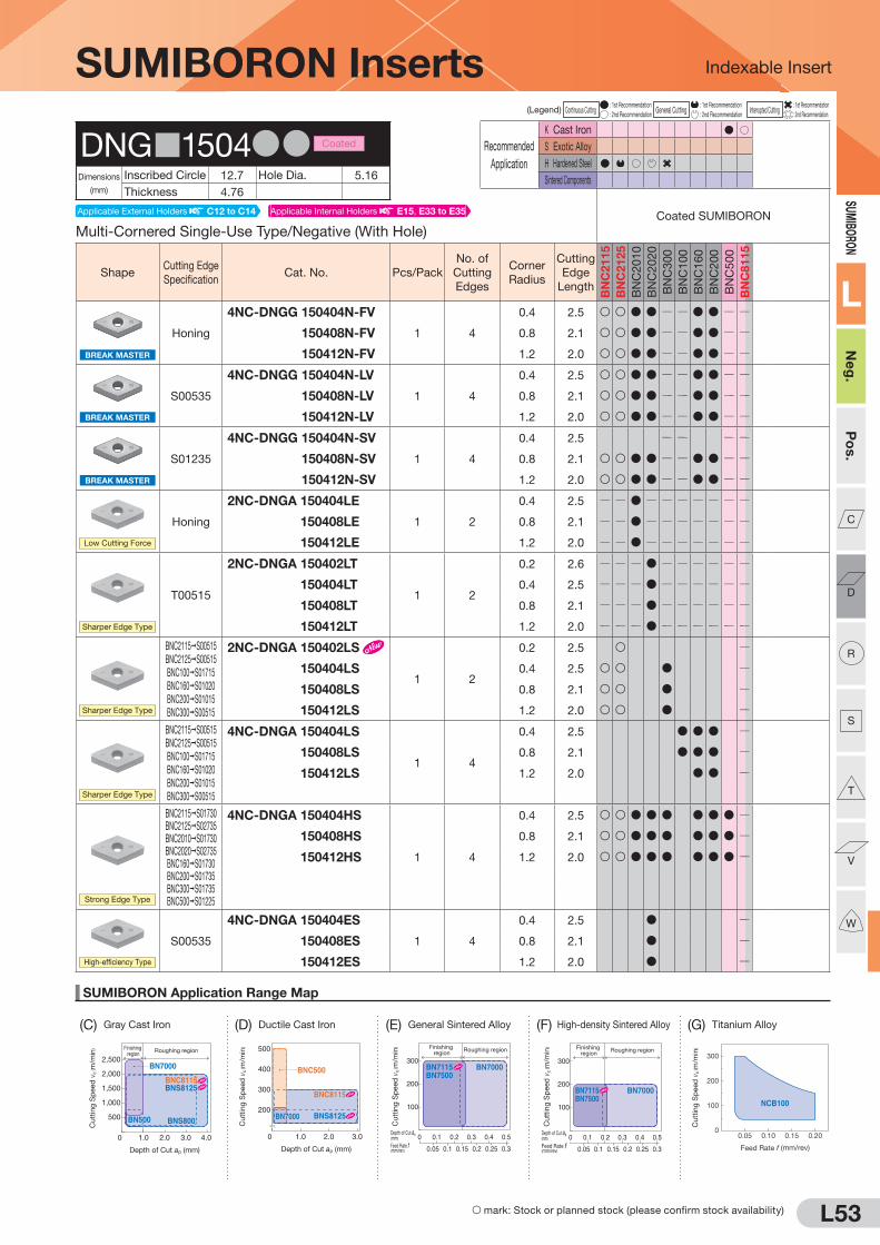
L53
SUMIBORON Application Range Map
(D) Ductile Cast Iron (G) Titanium Alloy
Indexable Insert
0 1.0 2.0 3.0
300
500
200
400
Depth of Cut ap (mm)
BNC500
BNC8115
BNS8125BN7000
Cutt
ing
Sp
eed
c
( m/m
in)
100
200
300
Depth of Cut ap(mm)
Feed Rate f(mm/rev)
0 0.1
0.150.10.05 0.2 0.25 0.3
0.2 0.3 0.4 0.5
Finishing region
Roughing region
BN7500BN7115 BN7000
Cutt
ing
Sp
eed
vc
( m/m
in)
Depth of Cut ap(mm)
Feed Rate f(mm/rev)
0 0.1
0.150.10.05 0.2 0.25 0.3
0.2 0.3 0.4 0.5
100
200
300
Finishing region
Roughing region
BN7500BN7115 BN7000
Cutt
ing
Sp
eed
vc
( m/m
in)
0
100
200
300
0.05 0.10 0.15 0.20
Feed Rate f (mm/rev)
NCB100
Cutt
ing
Sp
eed
vc
( m/m
in)Finishing
regionRoughing region
0 1.0 2.0 3.0 4.0
1,000
2,000
2,500
500
1,500
Depth of Cut ap (mm)
BNS800
BN7000
BN500
BNC8115BNS8125
Cutt
ing
Sp
eed
vc
( m/m
in)
SUMIBORON
L
Neg
.P
os.
C
D
R
S
T
V
W
(C) Gray Cast Iron (E) General Sintered Alloy (F) High-density Sintered Alloy
(Legend) Continuous Cutting : 1st Recommendation
General Cutting : 1st Recommendation
Interrupted Cutting : 1st Recommendation
: 2nd Recommendation : 2nd Recommendation : 2nd Recommendation
Recommended
Application
K Cast Iron
S Exotic Alloy
H Hardened Steel
Sintered Components
S mark: Stock or planned stock (please confirm stock availability)
SUMIBORON Inserts
Multi-Cornered Single-Use Type/Negative (With Hole)Coated SUMIBORON
ShapeCutting Edge
SpecificationCat. No. Pcs/Pack
No. of
Cutting
Edges
Corner
Radius
Cutting
Edge
Length
BN
C2
11
5
BN
C2
12
5
BN
C2
01
0
BN
C2
02
0
BN
C3
00
BN
C1
00
BN
C1
60
BN
C2
00
BN
C5
00
BN
C8
11
5
BREAK MASTER
Honing
4NC-DNGG 150404N-FV
1 4
0.4 2.5 S S D D Q Q D D Q Q
4NC-DNGG 150408N-FV 0.8 2.1 S S D D Q Q D D Q Q
4NC-DNGG 150412N-FV 1.2 2.0 S S D D Q Q D D Q Q
BREAK MASTER
S00535
4NC-DNGG 150404N-LV
1 4
0.4 2.5 S S D D Q Q D D Q Q
4NC-DNGG 150408N-LV 0.8 2.1 S S D D Q Q D D Q Q
4NC-DNGG 150412N-LV 1.2 2.0 S S D D Q Q D D Q Q
BREAK MASTER
S01235
4NC-DNGG 150404N-SV
1 4
0.4 2.5 Q Q Q Q
4NC-DNGG 150408N-SV 0.8 2.1 S S D D Q Q D D Q Q
4NC-DNGG 150412N-SV 1.2 2.0 S S D D Q Q D D Q Q
Low Cutting Force
Honing
2NC-DNGA 150404LE
1 2
0.4 2.5 Q Q D Q Q Q Q Q Q Q
2NC-DNGA 150408LE 0.8 2.1 Q Q D Q Q Q Q Q Q Q
2NC-DNGA 150412LE 1.2 2.0 Q Q D Q Q Q Q Q Q Q
T00515
2NC-DNGA 150402LT
1 2
0.2 2.6 Q Q Q D Q Q Q Q Q Q
2NC-DNGA 150404LT 0.4 2.5 Q Q Q D Q Q Q Q Q Q
2NC-DNGA 150408LT 0.8 2.1 Q Q Q D Q Q Q Q Q Q
2NC-DNGA 150412LT 1.2 2.0 Q Q Q D Q Q Q Q Q Q
BNC2115 S00515
BNC2125 S00515
BNC100 S01715
BNC160 S01020
BNC200 S01015
BNC300 S00515
2NC-DNGA 150402LS
1 2
0.2 2.5 S Q
2NC-DNGA 150404LS 0.4 2.5 S S D Q
2NC-DNGA 150408LS 0.8 2.1 S S D Q
2NC-DNGA 150412LS 1.2 2.0 S S D Q
BNC2115 S00515
BNC2125 S00515
BNC100 S01715
BNC160 S01020
BNC200 S01015
BNC300 S00515
4NC-DNGA 150404LS
1 4
0.4 2.5 D D D Q
4NC-DNGA 150408LS 0.8 2.1 D D D Q
4NC-DNGA 150412LS 1.2 2.0 D D Q
BNC2115 S01730BNC2125 S02735BNC2010 S01730BNC2020 S02735BNC160 S01730BNC200 S01735BNC300 S01735BNC500 S01225
4NC-DNGA 150404HS
1 4
0.4 2.5 S S D D D D D D Q
4NC-DNGA 150408HS 0.8 2.1 S S D D D D D D Q
4NC-DNGA 150412HS 1.2 2.0 S S D D D D D D Q
High-efficiency Type
S00535
4NC-DNGA 150404ES
1 4
0.4 2.5 D Q
4NC-DNGA 150408ES 0.8 2.1 D Q
4NC-DNGA 150412ES 1.2 2.0 D Q
Sharper Edge Type
Sharper Edge Type
Sharper Edge Type
Strong Edge Type
DNG 1504DD Coated
Dimensions
(mm)
Inscribed Circle 12.7 Hole Dia. 5.16
Thickness 4.76
Applicable Internal Holders E15, E33 to E35Applicable External Holders C12 to C14
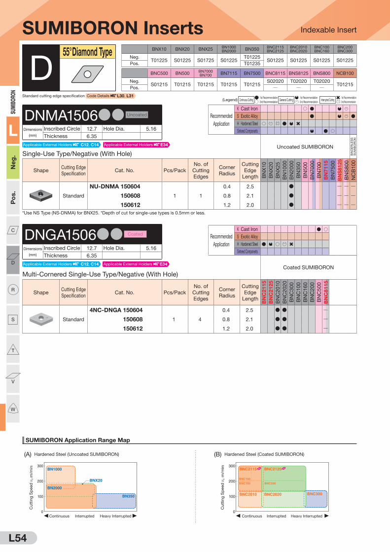
L54
SUMIBORON Application Range Map
Indexable Insert
300
200
100
0Heavy InterruptedContinuous Interrupted
BNX20
BN1000
BN350
BN2000
Cu
ttin
g S
peed
vc
( m/m
in) 300
200
100
0Heavy InterruptedContinuous Interrupted
BNC2010 BNC2020
BNC160
BNC100
BNC200
BNC2115 BNC2125
BNC300
Cu
ttin
g S
peed
vc
( m/m
in)
(A) Hardened Steel (Uncoated SUMIBORON) (B) Hardened Steel (Coated SUMIBORON)
SUMIBORO
N
L
Neg.
Pos.
C
D
R
S
T
V
W
Recommended
Application
K Cast Iron
S Exotic Alloy
H Hardened Steel
Sintered Components
BNX10 BNX20 BNX25BN1000BN2000 BN350
BNC2115BNC2125
BNC2010BNC2020
BNC100BNC160
BNC200BNC300
Neg.T01225 S01225 S01725 S01225
T01225S01225 S01225 S01225 S01225
Pos. T01235
BNC500 BN500BN7000BN700 BN7115 BN7500 BNC8115 BNS8125 BNS800 NCB100
Neg.S01215 T01215 T01215 T01215 T01215
S02020 T02020 T02020T01215
Pos. Q Q Q
(Legend) Continuous Cutting : 1st Recommendation
General Cutting : 1st Recommendation
Interrupted Cutting : 1st Recommendation
: 2nd Recommendation : 2nd Recommendation : 2nd Recommendation
Recommended
Application
K Cast Iron
S Exotic Alloy
H Hardened Steel
Sintered Components
Single-Use Type/Negative (With Hole)Uncoated SUMIBORON
BIN
DE
RLE
SS
S
UM
IBO
RO
N
ShapeCutting Edge
SpecificationCat. No. Pcs/Pack
No. of
Cutting
Edges
Corner
Radius
Cutting
Edge
Length BN
X1
0
BN
X2
0
BN
X2
5
BN
10
00
BN
20
00
BN
35
0
BN
50
0
BN
70
00
BN
70
0
BN
71
15
BN
75
00
BN
S8125
BN
S8
00
NC
B1
00
Standard
NU-DNMA 150604
1 1
0.4 2.5 D Q Q Q
NU-DNMA 150608 0.8 2.1 D Q Q Q
NU-DNMA 150612 1.2 2.0 D Q Q Q*Use NS Type (NS-DNMA) for BNX25. *Depth of cut for single-use types is 0.5mm or less.
SUMIBORON Inserts
Multi-Cornered Single-Use Type/Negative (With Hole)Coated SUMIBORON
ShapeCutting Edge
SpecificationCat. No. Pcs/Pack
No. of
Cutting
Edges
Corner
Radius
Cutting
Edge
Length
BN
C2
11
5
BN
C2
12
5
BN
C2
01
0
BN
C2
02
0
BN
C3
00
BN
C1
00
BN
C1
60
BN
C2
00
BN
C5
00
BN
C8
11
5
Standard
4NC-DNGA 150604
1 4
0.4 2.5 D D Q
4NC-DNGA 150608 0.8 2.1 D D Q
4NC-DNGA 150612 1.2 2.0 D D Q
D55° Diamond Type
DNMA1506DD Uncoated
Dimensions
(mm)
Inscribed Circle 12.7 Hole Dia. 5.16
Thickness 6.35
DNGA1506DD Coated
Dimensions
(mm)
Inscribed Circle 12.7 Hole Dia. 5.16
Thickness 6.35
Standard cutting edge specification Code Details L30, L31
Applicable External Holders E34Applicable External Holders C12, C14
Applicable External Holders E34Applicable External Holders C12, C14

L55
SUMIBORON Application Range Map
(D) Ductile Cast Iron (G) Titanium Alloy
Indexable Insert
0 1.0 2.0 3.0
300
500
200
400
Depth of Cut ap (mm)
BNC500
BNC8115
BNS8125BN7000
Cutt
ing
Sp
eed
vc
( m/m
in)
100
200
300
Depth of Cut ap(mm)
Feed Rate f(mm/rev)
0 0.1
0.150.10.05 0.2 0.25 0.3
0.2 0.3 0.4 0.5
Finishing region
Roughing region
BN7500BN7115 BN7000
Cutt
ing
Sp
eed
vc
( m/m
in)
Depth of Cut ap(mm)
Feed Rate f(mm/rev)
0 0.1
0.150.10.05 0.2 0.25 0.3
0.2 0.3 0.4 0.5
100
200
300
Finishing region
Roughing region
BN7500BN7115 BN7000
Cutt
ing
Sp
eed
vc
( m/m
in)
0
100
200
300
0.05 0.10 0.15 0.20
Feed Rate f (mm/rev)
NCB100
Cutt
ing
Sp
eed
vc
( m/m
in)Finishing
regionRoughing region
0 1.0 2.0 3.0 4.0
1,000
2,000
2,500
500
1,500
Depth of Cut ap (mm)
BNS800
BN7000
BN500
BNC8115BNS8125
Cutt
ing
Sp
eed
vc
( m/m
in)
SUMIBO
RON
L
Neg.
Pos.
C
D
R
S
T
V
W
(C) Gray Cast Iron (E) General Sintered Alloy (F) High-density Sintered Alloy
Recommended
Application
K Cast Iron
S Exotic Alloy
H Hardened Steel
Sintered Components
(Legend) Continuous Cutting : 1st Recommendation
General Cutting : 1st Recommendation
Interrupted Cutting : 1st Recommendation
: 2nd Recommendation : 2nd Recommendation : 2nd Recommendation
Recommended
Application
K Cast Iron
S Exotic Alloy
H Hardened Steel
Sintered Components
SUMIBORON Inserts
Solid Type/Negative (Without Hole)Uncoated SUMIBORON
BIN
DE
RLE
SS
S
UM
IBO
RO
N
ShapeCutting Edge
SpecificationCat. No. Pcs/Pack
No. of
Cutting
Edges
Corner
Radius
Cutting
Edge
Length BN
X1
0
BN
X2
0
BN
X2
5
BN
10
00
BN
20
00
BN
35
0
BN
50
0
BN
70
00
BN
70
0
BN
71
15
BN
75
00
BN
S8
12
5
BN
S8
00
NC
B1
00
Standard
DNGN 110308
1 Solid
0.8 10.8 Q Q Q Q Q Q Q Q Q Q Q D D Q
DNGN 110312 1.2 10.5 Q Q Q Q Q Q Q Q Q Q Q D D Q
Low Cutting Force
Sharp
Edge
DNGN 110308LF
1 Solid
0.8 10.8 Q Q Q Q Q Q Q Q Q Q Q D Q
DNGN 110312LF 1.2 10.5 Q Q Q Q Q Q Q Q Q Q Q D Q
D55° Diamond Type
DNGN1103DD Uncoated
Dimensions
(mm)
Inscribed Circle 9.525 Hole Dia. QThickness 3.18
Solid Type/Negative (Without Hole)Coated SUMIBORON
ShapeCutting Edge
SpecificationCat. No. Pcs/Pack
No. of
Cutting
Edges
Corner
Radius
Cutting
Edge
Length
BN
C2
11
5
BN
C2
12
5
BN
C2
01
0
BN
C2
02
0
BN
C3
00
BN
C1
00
BN
C1
60
BN
C2
00
BN
C5
00
BN
C8
11
5
Standard
DNGN 110308
1 Solid
0.8 10.8 Q Q Q Q Q Q Q Q Q D
DNGN 110312 1.2 10.5 Q Q Q Q Q Q Q Q Q D
DNGN1103DD Coated
Dimensions
(mm)
Inscribed Circle 9.525 Hole Dia. QThickness 3.18
Applicable External Holders L113
Applicable External Holders L113

L56
SUMIBORON Application Range Map
Indexable Insert
300
200
100
0Heavy InterruptedContinuous Interrupted
BNX20
BN1000
BN350
BN2000
Cu
ttin
g S
peed
vc
( m/m
in) 300
200
100
0Heavy InterruptedContinuous Interrupted
BNC2010 BNC2020
BNC160
BNC100
BNC200
BNC2115 BNC2125
BNC300
Cu
ttin
g S
peed
vc
( m/m
in)
(A) Hardened Steel (Uncoated SUMIBORON) (B) Hardened Steel (Coated SUMIBORON)
SUMIBORO
N
L
Neg.
Pos.
C
D
R
S
T
V
W
BNX10 BNX20 BNX25BN1000BN2000 BN350
BNC2115BNC2125
BNC2010BNC2020
BNC100BNC160
BNC200BNC300
Neg.T01225 S01225 S01725 S01225
T01225S01225 S01225 S01225 S01225
Pos. T01235
BNC500 BN500BN7000BN700 BN7115 BN7500 BNC8115 BNS8125 BNS800 NCB100
Neg.S01215 T01215 T01215 T01215 T01215
S02020 T02020 T02020T01215
Pos. Q Q Q
(Legend) Continuous Cutting : 1st Recommendation
General Cutting : 1st Recommendation
Interrupted Cutting : 1st Recommendation
: 2nd Recommendation : 2nd Recommendation : 2nd Recommendation
Recommended
Application
K Cast Iron
S Exotic Alloy
H Hardened Steel
Sintered Components
Multi-Cornered Single-Use Type/7° Positive (With Hole)
ShapeCutting Edge
SpecificationCat. No. Pcs/Pack
No. of
Cutting
Edges
Corner
Radius
Cutting
Edge
Length BN
X1
0
BN
X2
0
BN
X2
5
BN
10
00
BN
20
00
BN
35
0
BN
50
0
BN
70
00
BN
70
0
BN
71
15
BN
75
00
BN
S8125
BN
S8
00
NC
B1
00
Standard
2NU-DCGW 070204
1 2
0.4 2.5 D D D Q Q
2NU-DCGW 070208 0.8 2.1 D D D Q Q
BREAK MASTER
Honing
2NU-DCGT 070204N-FV
1 2
0.4 2.4 Q Q Q Q D Q Q Q Q Q Q Q Q Q
*Use 2NS Type (2NS-DCGW) for BNX25. *Depth of cut for single-use types is 0.5mm or less.
SUMIBORON Inserts
Single-Use Type/7° Positive (With Hole)Uncoated SUMIBORON
BIN
DE
RLE
SS
S
UM
IBO
RO
N
ShapeCutting Edge
SpecificationCat. No. Pcs/Pack
No. of
Cutting
Edges
Corner
Radius
Cutting
Edge
Length BN
X1
0
BN
X2
0
BN
X2
5
BN
10
00
BN
20
00
BN
35
0
BN
50
0
BN
70
00
BN
70
0
BN
71
15
BN
75
00
BN
S8125
BN
S8
00
NC
B1
00
Standard
NU-DCGW 070202
1 1
0.2 2.7 D D Q Q
NU-DCGW 070204 0.4 2.5 D D D F Q Q D
NU-DCGW 070208 0.8 2.1 D Q Q
T-NU-DCGW 070202
10 1
0.2 2.7 D Q Q Q
T-NU-DCGW 070204 0.4 2.5 D Q Q Q
T-NU-DCGW 070208 0.8 2.1 Q Q Q
Sharper Edge Type
T01215
NU-DCGW 070202LT
1 1
0.2 2.7 Q Q Q Q D Q Q Q Q Q Q Q Q Q
NU-DCGW 070204LT 0.4 2.5 Q Q Q Q D Q Q Q Q Q Q Q Q Q
NU-DCGW 070208LT 0.8 2.1 Q Q Q Q D Q Q Q Q Q Q Q Q Q
Strong Edge Type
S01235
NU-DCGW 070202HS
1 1
0.2 2.7 Q Q Q Q D Q Q Q Q Q Q Q Q
NU-DCGW 070204HS 0.4 2.5 Q Q Q Q D Q Q Q Q Q Q Q Q
*Use NS Type (NS-DCGW) for BNX25. *Depth of cut for single-use types is 0.5mm or less.
D55° Diamond Type
DCG 0702DD Uncoated
Dimensions
(mm)
Inscribed Circle 6.35 Hole Dia. 2.8
Thickness 2.38
Standard cutting edge specification Code Details L30, L31
Applicable Internal Holders E16, E28 to E32Applicable External Holders C17, D14, D18, D19, D24, D25
F mark: To be replaced by a new product, made to order, or discontinued (please confirm stock availability).

L57
SUMIBORON Application Range Map
(D) Ductile Cast Iron (G) Titanium Alloy
Indexable Insert
0 1.0 2.0 3.0
300
500
200
400
Depth of Cut ap (mm)
BNC500
BNC8115
BNS8125BN7000
Cutt
ing
Sp
eed
vc
( m/m
in)
100
200
300
Depth of Cut ap(mm)
Feed Rate f(mm/rev)
0 0.1
0.150.10.05 0.2 0.25 0.3
0.2 0.3 0.4 0.5
Finishing region
Roughing region
BN7500BN7115 BN7000
Cutt
ing
Sp
eed
vc
( m/m
in)
Depth of Cut ap(mm)
Feed Rate f(mm/rev)
0 0.1
0.150.10.05 0.2 0.25 0.3
0.2 0.3 0.4 0.5
100
200
300
Finishing region
Roughing region
BN7500BN7115 BN7000
Cutt
ing
Sp
eed
vc
( m/m
in)
0
100
200
300
0.05 0.10 0.15 0.20
Feed Rate f (mm/rev)
NCB100
Cutt
ing
Sp
eed
vc
( m/m
in)Finishing
regionRoughing region
0 1.0 2.0 3.0 4.0
1,000
2,000
2,500
500
1,500
Depth of Cut ap (mm)
BNS800
BN7000
BN500
BNC8115BNS8125
Cutt
ing
Sp
eed
vc
( m/m
in)
SUMIBORON
L
Neg
.P
os.
C
D
R
S
T
V
W
(C) Gray Cast Iron (E) General Sintered Alloy (F) High-density Sintered Alloy
(Legend) Continuous Cutting : 1st Recommendation
General Cutting : 1st Recommendation
Interrupted Cutting : 1st Recommendation
: 2nd Recommendation : 2nd Recommendation : 2nd Recommendation
Recommended
Application
K Cast Iron
S Exotic Alloy
H Hardened Steel
Sintered Components
SUMIBORON Inserts
Multi-Cornered Single-Use Type/7° Positive (With Hole)Coated SUMIBORON
ShapeCutting Edge
SpecificationCat. No. Pcs/Pack
No. of
Cutting
Edges
Corner
Radius
Cutting
Edge
Length
BN
C2
11
5
BN
C2
12
5
BN
C2
01
0
BN
C2
02
0
BN
C3
00
BN
C1
00
BN
C1
60
BN
C2
00
BN
C5
00
BN
C8
11
5
Standard
2NC-DCGW 070202
1 2
0.2 2.6 S S D D D Q
2NC-DCGW 070204 0.4 2.5 S S D D D D Q
2NC-DCGW 070208 0.8 2.1 S S D D Q
BREAK MASTER
Honing
2NC-DCGT 070204N-FV
1 2
0.4 2.4 S S D D Q Q D D Q Q
Sharper Edge Type
T00515
2NC-DCGW 070202LT
1 2
0.2 2.6 Q Q Q D Q Q Q Q Q Q
2NC-DCGW 070204LT 0.4 2.5 Q Q Q D Q Q Q Q Q Q
Sharper Edge Type
BNC2115 S00515
BNC2125 S00515
BNC100 S01715
BNC160 S01020
BNC200 S01015
BNC300 S00515
2NC-DCGW 070202LS
1 2
0.2 2.6 S S D Q
2NC-DCGW 070204LS 0.4 2.5 S S D Q
2NC-DCGW 070208LS 0.8 2.1 S S Q
D55° Diamond Type
DCG 0702DD Coated
Dimensions
(mm)
Inscribed Circle 6.35 Hole Dia. 2.8
Thickness 2.38
Applicable Internal Holders E16, E28 to E32Applicable External Holders C17, D14, D18, D19, D24, D25
S mark: Stock or planned stock (please confirm stock availability)

L58
SUMIBORON Application Range Map
Indexable Insert
300
200
100
0Heavy InterruptedContinuous Interrupted
BNX20
BN1000
BN350
BN2000
Cut
ting
Sp
eed
vc
( m/m
in) 300
200
100
0Heavy InterruptedContinuous Interrupted
BNC2010 BNC2020
BNC160
BNC100
BNC200
BNC2115 BNC2125
BNC300
Cut
ting
Sp
eed
vc
( m/m
in)
(A) Hardened Steel (Uncoated SUMIBORON) (B) Hardened Steel (Coated SUMIBORON)
SUMI
BORO
N
L
Neg
.P
os.
C
D
R
S
T
V
W
F mark: To be replaced by a new product, made to order, or discontinued (please confirm stock availability).
BNX10 BNX20 BNX25BN1000BN2000 BN350
BNC2115BNC2125
BNC2010BNC2020
BNC100BNC160
BNC200BNC300
Neg.T01225 S01225 S01725 S01225
T01225S01225 S01225 S01225 S01225
Pos. T01235
BNC500 BN500BN7000BN700 BN7115 BN7500 BNC8115 BNS8125 BNS800 NCB100
Neg.S01215 T01215 T01215 T01215 T01215
S02020 T02020 T02020T01215
Pos. Q Q Q
(Legend) Continuous Cutting : 1st Recommendation
General Cutting : 1st Recommendation
Interrupted Cutting : 1st Recommendation
: 2nd Recommendation : 2nd Recommendation : 2nd Recommendation
Recommended
Application
K Cast Iron
S Exotic Alloy
H Hardened Steel
Sintered Components
SUMIBORON Inserts
Single-Use Type/7° Positive (With Hole)Uncoated SUMIBORON
BIN
DE
RLE
SS
S
UM
IBO
RO
N
ShapeCutting Edge
SpecificationCat. No. Pcs/Pack
No. of
Cutting
Edges
Corner
Radius
Cutting
Edge
Length BN
X1
0
BN
X2
0
BN
X2
5
BN
10
00
BN
20
00
BN
35
0
BN
50
0
BN
70
00
BN
70
0
BN
71
15
BN
75
00
BN
S8125
BN
S8
00
NC
B1
00
Standard
NU-DCGW 11T302
1 1
0.2 2.7 D D D F Q Q
NU-DCGW 11T304 0.4 2.5 D D D F Q Q D
NU-DCGW 11T308 0.8 2.1 D Q Q D
NU-DCGW 11T312 1.2 2.0 D Q Q
T-NU-DCGW 11T302
10 1
0.2 2.7 D Q Q Q
T-NU-DCGW 11T304 0.4 2.5 D Q Q Q
T-NU-DCGW 11T308 0.8 2.1 Q Q Q
T-NU-DCGW 11T312 1.2 2.0 Q Q Q
Low Cutting Force
Sharp
Edge
NU-DCGW 11T302LF
1 1
0.2 2.7 Q Q Q Q Q Q Q D F Q Q
NU-DCGW 11T304LF 0.4 2.5 Q Q Q Q Q Q Q D F Q Q
NU-DCGW 11T308LF 0.8 2.1 Q Q Q Q Q Q Q Q Q
Sharper Edge Type
T01215
NU-DCGW 11T302LT
1 1
0.2 2.7 Q Q Q Q D Q Q Q Q Q Q Q Q Q
NU-DCGW 11T304LT 0.4 2.5 Q Q Q Q D Q Q Q Q Q Q Q Q Q
NU-DCGW 11T308LT 0.8 2.1 Q Q Q Q D Q Q Q Q Q Q Q Q Q
NU-DCGW 11T312LT 1.2 2.0 Q Q Q Q D Q Q Q Q Q Q Q Q Q
Strong Edge Type
S01235
NU-DCGW 11T302HS
1 1
0.2 2.7 Q Q Q Q D Q Q Q Q Q Q Q Q
NU-DCGW 11T304HS 0.4 2.5 Q Q Q Q D Q Q Q Q Q Q Q Q
NU-DCGW 11T308HS 0.8 2.1 Q Q Q Q D Q Q Q Q Q Q Q Q
*Use NS Type (NS-DCGW) for BNX25. *Depth of cut for single-use types is 0.5mm or less.
D55° Diamond Type
DCG 11T3DD Uncoated
Dimensions
(mm)
Inscribed Circle 9.525 Hole Dia. 4.4
Thickness 3.97
Applicable Internal Holders E13, E28 to E32Applicable External Holders C17, D14, D24, D25
Standard cutting edge specification Code Details L30, L31

L59
SUMIBORON Application Range Map
(D) Ductile Cast Iron (G) Titanium Alloy
Indexable Insert
0 1.0 2.0 3.0
300
500
200
400
Depth of Cut ap (mm)
BNC500
BNC8115
BNS8125BN7000
Cut
ting
Sp
eed
vc
( m/m
in)
100
200
300
Depth of Cut ap(mm)
Feed Rate f(mm/rev)
0 0.1
0.150.10.05 0.2 0.25 0.3
0.2 0.3 0.4 0.5
Finishing region Roughing region
BN7500BN7115 BN7000
Cut
ting
Sp
eed
vc
( m/m
in)
Depth of Cut ap(mm)
Feed Rate f(mm/rev)
0 0.1
0.150.10.05 0.2 0.25 0.3
0.2 0.3 0.4 0.5
100
200
300
Finishing region Roughing region
BN7500BN7115 BN7000
Cut
ting
Sp
eed
vc
( m/m
in)
0
100
200
300
0.05 0.10 0.15 0.20
Feed Rate f (mm/rev)
NCB100
Cut
ting
Sp
eed
vc
( m/m
in)Finishing
region Roughing region
0 1.0 2.0 3.0 4.0
1,000
2,000
2,500
500
1,500
Depth of Cut ap (mm)
BNS800
BN7000
BN500
BNC8115BNS8125
Cut
ting
Sp
eed
vc
( m/m
in)
SUMIBORON
L
Neg
.P
os.
C
D
R
S
T
V
W
(C) Gray Cast Iron (E) General Sintered Alloy (F) High-density Sintered Alloy
(Legend) Continuous Cutting : 1st Recommendation
General Cutting : 1st Recommendation
Interrupted Cutting : 1st Recommendation
: 2nd Recommendation : 2nd Recommendation : 2nd Recommendation
Recommended
Application
K Cast Iron
S Exotic Alloy
H Hardened Steel
Sintered Components
SUMIBORON Inserts
Multi-Cornered Single-Use Type/7° Positive (With Hole)Uncoated SUMIBORON
BIN
DE
RLE
SS
S
UM
IBO
RO
N
ShapeCutting Edge
SpecificationCat. No. Pcs/Pack
No. of
Cutting
Edges
Corner
Radius
Cutting
Edge
Length BN
X1
0
BN
X2
0
BN
X2
5
BN
10
00
BN
20
00
BN
35
0
BN
50
0
BN
70
00
BN
70
0
BN
71
15
BN
75
00
BN
S8125
BN
S8
00
NC
B1
00
Standard
2NU-DCGW 11T302
1 2
0.2 2.7 D D D Q Q
2NU-DCGW 11T304 0.4 2.5 D D D Q Q
2NU-DCGW 11T308 0.8 2.1 D D D Q Q
T-2NU-DCGW 11T302
10 2
0.2 2.7 Q Q Q
T-2NU-DCGW 11T304 0.4 2.5 D D Q Q Q
T-2NU-DCGW 11T308 0.8 2.1 Q Q Q
Wiper Insert
S01215
2NU-DCGW 11T304WG*1
1 2
0.4 2.3 Q Q Q Q D Q Q Q Q Q Q Q Q
2NU-DCGW 11T308WG*1
0.8 2.1 Q Q Q Q D Q Q Q Q Q Q Q Q
Wiper Insert
S01215
2NU-DCGW 11T304WH*1
1 2
0.4 2.1 Q Q Q Q D Q Q Q Q Q Q Q Q
2NU-DCGW 11T308WH*1
0.8 1.8 Q Q Q Q D Q Q Q Q Q Q Q Q
BREAK MASTER
Honing
2NU-DCGT 11T304N-FV
1 2
0.4 2.4 Q Q Q Q D Q Q Q Q Q Q Q Q Q
2NU-DCGT 11T308N-FV 0.8 2.0 Q Q Q Q D Q Q Q Q Q Q Q Q Q
BREAK MASTER
S00535
2NU-DCGT 11T304N-LV
1 2
0.4 2.4 Q Q Q Q D Q Q Q Q Q Q Q Q Q
2NU-DCGT 11T308N-LV 0.8 2.0 Q Q Q Q D Q Q Q Q Q Q Q Q Q
Low Cutting Force
Sharp
Edge
2NU-DCGW 11T302LF
1 2
0.2 2.7 Q Q Q Q Q Q Q D Q D D Q Q
2NU-DCGW 11T304LF 0.4 2.5 Q Q Q Q Q Q Q D Q D D Q Q
2NU-DCGW 11T308LF 0.8 2.1 D Q D D Q Q
Low Cutting Force
Honing
2NU-DCGW 11T302LE
1 2
0.2 2.7 Q Q Q Q Q Q Q Q D D Q Q
2NU-DCGW 11T304LE 0.4 2.5 Q Q Q Q Q Q Q Q D D Q Q
2NU-DCGW 11T308LE 0.8 2.1 Q Q Q Q Q Q Q Q D D Q Q
General-purpose Type for Continuous Cutting
BN7115 S00515
BN7500 S00715
2NU-DCGW 11T302LS
1 2
0.2 2.7 Q Q Q Q Q Q Q Q D D Q Q
2NU-DCGW 11T304LS 0.4 2.5 Q Q Q Q Q Q Q Q D D Q Q
2NU-DCGW 11T308LS 0.8 2.1 Q Q Q Q Q Q Q Q D D Q Q
*Use 2NS Type (2NS-DCGW) for BNX25.
*Depth of cut for single-use types is 0.5mm or less.
*1 Use a holder with a cutting angle of 93°.
D55° Diamond Type
DCG 11T3DD Uncoated
Dimensions
(mm)
Inscribed Circle 9.525 Hole Dia. 4.4
Thickness 3.97
Applicable Internal Holders E13, E28 to E32Applicable External Holders C17, D14, D18, D19, D24, D25

L60
SUMIBORON Application Range Map
Indexable Insert
300
200
100
0Heavy InterruptedContinuous Interrupted
BNX20
BN1000
BN350
BN2000
Cut
ting
Sp
eed
vc
( m/m
in) 300
200
100
0Heavy InterruptedContinuous Interrupted
BNC2010 BNC2020
BNC160
BNC100
BNC200
BNC2115 BNC2125
BNC300
Cut
ting
Sp
eed
vc
( m/m
in)
(A) Hardened Steel (Uncoated SUMIBORON) (B) Hardened Steel (Coated SUMIBORON)
SUMI
BORO
N
L
Neg
.P
os.
C
D
R
S
T
V
W
BNX10 BNX20 BNX25BN1000BN2000 BN350
BNC2115BNC2125
BNC2010BNC2020
BNC100BNC160
BNC200BNC300
Neg.T01225 S01225 S01725 S01225
T01225S01225 S01225 S01225 S01225
Pos. T01235
BNC500 BN500BN7000BN700 BN7115 BN7500 BNC8115 BNS8125 BNS800 NCB100
Neg.S01215 T01215 T01215 T01215 T01215
S02020 T02020 T02020T01215
Pos. Q Q Q
(Legend) Continuous Cutting : 1st Recommendation
General Cutting : 1st Recommendation
Interrupted Cutting : 1st Recommendation
: 2nd Recommendation : 2nd Recommendation : 2nd Recommendation
Recommended
Application
K Cast Iron
S Exotic Alloy
H Hardened Steel
Sintered Components
SUMIBORON Inserts
Multi-Cornered Single-Use Type/7° Positive (With Hole)Coated SUMIBORON
ShapeCutting Edge
SpecificationCat. No. Pcs/Pack
No. of
Cutting
Edges
Corner
Radius
Cutting
Edge
Length
BN
C2
11
5
BN
C2
12
5
BN
C2
01
0
BN
C2
02
0
BN
C3
00
BN
C1
00
BN
C1
60
BN
C2
00
BN
C5
00
BN
C8
11
5
Standard
2NC-DCGW 11T302
1 2
0.2 2.7 S S D D D D D Q2NC-DCGW 11T304 0.4 2.5 S S D D D D D D D Q2NC-DCGW 11T308 0.8 2.1 S S D D D D D D D Q
Wiper Insert
S01215
2NC-DCGW 11T304WG*1
1 2
0.4 2.3 S S D D Q Q D D Q2NC-DCGW 11T308WG
*10.8 2.1 S S D D Q Q D D Q
Wiper Insert
S01215
2NC-DCGW 11T304WH*1
1 2
0.4 2.1 S S D D Q Q D D Q2NC-DCGW 11T308WH
*10.8 1.8 S S D D Q Q D D Q
BREAK MASTER
Honing
2NC-DCGT 11T304N-FV
1 2
0.4 2.4 S S D D Q Q D D Q Q2NC-DCGT 11T308N-FV 0.8 2.0 S S D D Q Q D D Q Q
BREAK MASTER
S00535
2NC-DCGT 11T304N-LV
1 2
0.4 2.4 S S D D Q Q D D Q Q2NC-DCGT 11T308N-LV 0.8 2.0 S S D D Q Q D D Q Q
Low Cutting Force
Honing
2NC-DCGW 11T302LE
1 2
0.2 2.7 Q Q D Q Q Q Q Q Q Q2NC-DCGW 11T304LE 0.4 2.5 Q Q D Q Q Q Q Q Q Q2NC-DCGW 11T308LE 0.8 2.1 Q Q D Q Q Q Q Q Q Q
Sharper Edge Type
T00515
2NC-DCGW 11T302LT
1 2
0.2 2.7 Q Q Q D Q Q Q Q Q Q2NC-DCGW 11T304LT 0.4 2.5 Q Q Q D Q Q Q Q Q Q2NC-DCGW 11T308LT 0.8 2.1 Q Q Q D Q Q Q Q Q Q
Sharper Edge Type
BNC2115 S00515BNC2125 S00515BNC100 S01715BNC160 S01020BNC200 S01015BNC300 S00515
2NC-DCGW 11T302LS
1 2
0.2 2.7 S S D D Q2NC-DCGW 11T304LS 0.4 2.5 S S D D D D Q2NC-DCGW 11T308LS 0.8 2.1 S S D D D D Q
Strong Edge Type
BNC2115 S01730BNC2125 S02735BNC2010 S01730BNC2020 S02735BNC160 S01730BNC200 S01735BNC300 S01735BNC500 S01225
2NC-DCGW 11T304HS
1 2
0.4 2.5 D Q2NC-DCGW 11T308HS 0.8 2.1 D Q
*1 Use a holder with a cutting angle of 93°.
D55° Diamond Type
DCG 11T3DD Coated
Dimensions
(mm)
Inscribed Circle 9.525 Hole Dia. 4.4
Thickness 3.97
Standard cutting edge specification Code Details L30, L31
Applicable Internal Holders E13, E28 to E32Applicable External Holders C17, D14, D18, D19, D24, D25
S mark: Stock or planned stock (please confirm stock availability)
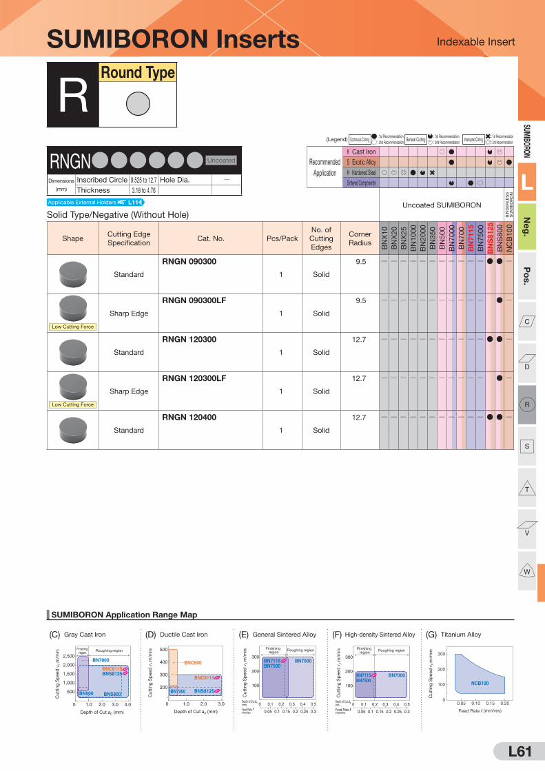
L61
SUMIBORON Application Range Map
(D) Ductile Cast Iron (G) Titanium Alloy
Indexable Insert
0 1.0 2.0 3.0
300
500
200
400
Depth of Cut ap (mm)
BNC500
BNC8115
BNS8125BN7000
Cuttin
g S
peed
vc ( m
/min
)
100
200
300
Depth of Cut ap(mm)
Feed Rate f(mm/rev)
0 0.1
0.150.10.05 0.2 0.25 0.3
0.2 0.3 0.4 0.5
Finishing region
Roughing region
BN7500BN7115 BN7000
Cuttin
g S
peed
vc ( m
/min
)
Depth of Cut ap(mm)
Feed Rate f(mm/rev)
0 0.1
0.150.10.05 0.2 0.25 0.3
0.2 0.3 0.4 0.5
100
200
300
Finishing region
Roughing region
BN7500BN7115 BN7000
Cuttin
g S
peed
vc ( m
/min
)
0
100
200
300
0.05 0.10 0.15 0.20
Feed Rate f (mm/rev)
NCB100
Cuttin
g S
peed
vc ( m
/min
)Finishing region
Roughing region
0 1.0 2.0 3.0 4.0
1,000
2,000
2,500
500
1,500
Depth of Cut ap (mm)
BNS800
BN7000
BN500
BNC8115BNS8125
Cuttin
g S
peed
vc ( m
/min
)
SUMIBORON
L
Neg
.P
os.
C
D
R
S
T
V
W
(C) Gray Cast Iron (E) General Sintered Alloy (F) High-density Sintered Alloy
(Legend) Continuous Cutting : 1st Recommendation
General Cutting : 1st Recommendation
Interrupted Cutting : 1st Recommendation
: 2nd Recommendation : 2nd Recommendation : 2nd Recommendation
Recommended
Application
K Cast Iron
S Exotic Alloy
H Hardened Steel
Sintered Components
SUMIBORON Inserts
Solid Type/Negative (Without Hole)Uncoated SUMIBORON
BIN
DE
RLE
SS
S
UM
IBO
RO
N
ShapeCutting Edge
SpecificationCat. No. Pcs/Pack
No. of
Cutting
Edges
Corner
Radius
BN
X1
0
BN
X2
0
BN
X2
5
BN
10
00
BN
20
00
BN
35
0
BN
50
0
BN
70
00
BN
70
0
BN
71
15
BN
75
00
BN
S8
12
5
BN
S8
00
NC
B1
00
Standard
RNGN 090300
1 Solid
9.5 Q Q Q Q Q Q Q Q Q Q Q D D Q
Low Cutting Force
Sharp Edge
RNGN 090300LF
1 Solid
9.5 Q Q Q Q Q Q Q Q Q Q Q D Q
Standard
RNGN 120300
1 Solid
12.7 Q Q Q Q Q Q Q Q Q Q Q D D Q
Low Cutting Force
Sharp Edge
RNGN 120300LF
1 Solid
12.7 Q Q Q Q Q Q Q Q Q Q Q D Q
Standard
RNGN 120400
1 Solid
12.7 Q Q Q Q Q Q Q Q Q Q Q D D Q
RRound Type
RNGNDDDDDD Uncoated
Dimensions
(mm)
Inscribed Circle 9.525 to 12.7 Hole Dia. QThickness 3.18 to 4.76
Applicable External Holders L114

L62
SUMIBORON Application Range Map
Indexable Insert
300
200
100
0Heavy InterruptedContinuous Interrupted
BNX20
BN1000
BN350
BN2000
Cu
ttin
g S
peed
vc
( m/m
in) 300
200
100
0Heavy InterruptedContinuous Interrupted
BNC2010 BNC2020
BNC160
BNC100
BNC200
BNC2115 BNC2125
BNC300
Cu
ttin
g S
peed
vc
( m/m
in)
(A) Hardened Steel (Uncoated SUMIBORON) (B) Hardened Steel (Coated SUMIBORON)
SUMI
BORO
N
L
Neg
.P
os.
C
D
R
S
T
V
W
BNX10 BNX20 BNX25BN1000BN2000 BN350
BNC2115BNC2125
BNC2010BNC2020
BNC100BNC160
BNC200BNC300
Neg.T01225 S01225 S01725 S01225
T01225S01225 S01225 S01225 S01225
Pos. T01235
BNC500 BN500BN7000BN700 BN7115 BN7500 BNC8115 BNS8125 BNS800 NCB100
Neg.S01215 T01215 T01215 T01215 T01215
S02020 T02020 T02020T01215
Pos. Q Q Q
(Legend) Continuous Cutting : 1st Recommendation
General Cutting : 1st Recommendation
Interrupted Cutting : 1st Recommendation
: 2nd Recommendation : 2nd Recommendation : 2nd Recommendation
Recommended
Application
K Cast Iron
S Exotic Alloy
H Hardened Steel
Sintered Components
SUMIBORON Inserts
Solid Type/Negative (Without Hole)Coated SUMIBORON
ShapeCutting Edge
SpecificationCat. No. Pcs/Pack
No. of
Cutting
Edges
Corner
Radius
BN
C2
11
5
BN
C2
12
5
BN
C2
01
0
BN
C2
02
0
BN
C3
00
BN
C1
00
BN
C1
60
BN
C2
00
BN
C5
00
BN
C8
11
5
Standard
RNGN 090300
1 Solid
9.5 Q Q Q Q Q Q Q Q Q D
Standard
RNGN 120300
1 Solid
12.7 Q Q Q Q Q Q Q Q Q D
Standard
RNGN 120400
1Solid
12.7 Q Q Q Q Q Q Q Q Q D
RRound Type
RNGNDDDDDD Coated
Dimensions
(mm)
Inscribed Circle 9.525 to 12.7 Hole Dia. QThickness 3.18 to 4.76
Standard cutting edge specification Code Details L30, L31
Applicable External Holders L114
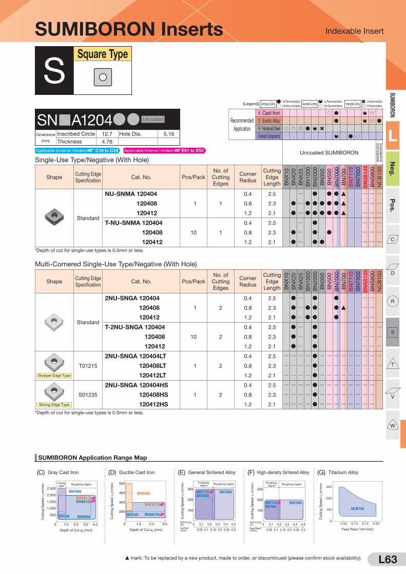
L63
SUMIBORON Application Range Map
(D) Ductile Cast Iron
Indexable Insert
0 1.0 2.0 3.0
300
500
200
400
Depth of Cut ap (mm)
BNC500
BNC8115
BNS8125BN7000
Cuttin
g S
peed
vc ( m
/min
)
100
200
300
Depth of Cut ap(mm)
Feed Rate f(mm/rev)
0 0.1
0.150.10.05 0.2 0.25 0.3
0.2 0.3 0.4 0.5
Finishing region
Roughing region
BN7500BN7115 BN7000
Cuttin
g S
peed
vc ( m
/min
)
Depth of Cut ap(mm)
Feed Rate f(mm/rev)
0 0.1
0.150.10.05 0.2 0.25 0.3
0.2 0.3 0.4 0.5
100
200
300
Finishing region
Roughing region
BN7500BN7115 BN7000
Cuttin
g S
peed
vc ( m
/min
)
0
100
200
300
0.05 0.10 0.15 0.20
Feed Rate f (mm/rev)
NCB100
Cuttin
g S
peed
vc ( m
/min
)Finishing region
Roughing region
0 1.0 2.0 3.0 4.0
1,000
2,000
2,500
500
1,500
Depth of Cut ap (mm)
BNS800
BN7000
BN500
BNC8115BNS8125
Cuttin
g S
peed
vc ( m
/min
)
SUMIBORON
L
Neg
.P
os.
C
D
R
S
T
V
W
(G) Titanium Alloy(C) Gray Cast Iron (E) General Sintered Alloy (F) High-density Sintered Alloy
(Legend) Continuous Cutting : 1st Recommendation
General Cutting : 1st Recommendation
Interrupted Cutting : 1st Recommendation
: 2nd Recommendation : 2nd Recommendation : 2nd Recommendation
Recommended
Application
K Cast Iron
S Exotic Alloy
H Hardened Steel
Sintered Components
F mark: To be replaced by a new product, made to order, or discontinued (please confirm stock availability).
SUMIBORON Inserts
Single-Use Type/Negative (With Hole)Uncoated SUMIBORON
BIN
DE
RLE
SS
S
UM
IBO
RO
N
ShapeCutting Edge
SpecificationCat. No. Pcs/Pack
No. of
Cutting
Edges
Corner
Radius
Cutting
Edge
Length BN
X1
0
BN
X2
0
BN
X2
5
BN
10
00
BN
20
00
BN
35
0
BN
50
0
BN
70
00
BN
70
0
BN
71
15
BN
75
00
BN
S8125
BN
S8
00
NC
B1
00
Standard
NU-SNMA 120404
1 1
0.4 2.5 Q D D D F Q Q Q
NU-SNMA 120408 0.8 2.3 D Q D D D D D F Q Q Q
NU-SNMA 120412 1.2 2.1 D Q D D D D D F Q Q Q
T-NU-SNMA 120404
10 1
0.4 2.5 Q D Q Q Q
T-NU-SNMA 120408 0.8 2.3 D Q D D Q Q Q
T-NU-SNMA 120412 1.2 2.1 D Q D D Q Q Q*Depth of cut for single-use types is 0.5mm or less.
SSquare Type
SN A1204DD Uncoated
Dimensions
(mm)
Inscribed Circle 12.7 Hole Dia. 5.16
Thickness 4.76
Multi-Cornered Single-Use Type/Negative (With Hole)
ShapeCutting Edge
SpecificationCat. No. Pcs/Pack
No. of
Cutting
Edges
Corner
Radius
Cutting
Edge
Length BN
X1
0
BN
X2
0
BN
X2
5
BN
10
00
BN
20
00
BN
35
0
BN
50
0
BN
70
00
BN
70
0
BN
71
15
BN
75
00
BN
S8125
BN
S8
00
NC
B1
00
Standard
2NU-SNGA 120404
1 2
0.4 2.5 D Q D D Q Q
2NU-SNGA 120408 0.8 2.3 D Q D D D F Q Q
2NU-SNGA 120412 1.2 2.1 D Q D D D Q Q
T-2NU-SNGA 120404
10 2
0.4 2.5 D Q D Q Q Q
T-2NU-SNGA 120408 0.8 2.3 D Q D Q Q Q
T-2NU-SNGA 120412 1.2 2.1 D Q D Q Q Q
Sharper Edge Type
T01215
2NU-SNGA 120404LT
1 2
0.4 2.5 Q Q Q Q D Q Q Q Q Q Q Q Q Q
2NU-SNGA 120408LT 0.8 2.3 Q Q Q Q D Q Q Q Q Q Q Q Q Q
2NU-SNGA 120412LT 1.2 2.1 Q Q Q Q D Q Q Q Q Q Q Q Q Q
Strong Edge Type
S01235
2NU-SNGA 120404HS
1 2
0.4 2.5 Q Q Q Q D Q Q Q Q Q Q Q Q
2NU-SNGA 120408HS 0.8 2.3 Q Q Q Q D Q Q Q Q Q Q Q Q
2NU-SNGA 120412HS 1.2 2.1 Q Q Q Q D Q Q Q Q Q Q Q Q
*Depth of cut for single-use types is 0.5mm or less.
Applicable External Holders C19 to C24 Applicable Internal Holders E51 to E53

L64
SUMIBORON Application Range Map
Indexable Insert
300
200
100
0Heavy InterruptedContinuous Interrupted
BNX20
BN1000
BN350
BN2000
Cu
ttin
g S
peed
vc
( m/m
in) 300
200
100
0Heavy InterruptedContinuous Interrupted
BNC2010 BNC2020
BNC160
BNC100
BNC200
BNC2115 BNC2125
BNC300
Cu
ttin
g S
peed
vc
( m/m
in)
(A) Hardened Steel (Uncoated SUMIBORON) (B) Hardened Steel (Coated SUMIBORON)
SUMI
BORO
N
L
Neg
.P
os.
C
D
R
S
T
V
W
Recommended
Application
K Cast Iron
S Exotic Alloy
H Hardened Steel
Sintered Components
S mark: Stock or planned stock item (please confirm stock availability) F: To be replaced by new item (please confirm stock availability)
BNX10 BNX20 BNX25BN1000BN2000 BN350
BNC2115BNC2125
BNC2010BNC2020
BNC100BNC160
BNC200BNC300
Neg.T01225 S01225 S01725 S01225
T01225S01225 S01225 S01225 S01225
Pos. T01235
BNC500 BN500BN7000BN700 BN7115 BN7500 BNC8115 BNS8125 BNS800 NCB100
Neg.S01215 T01215 T01215 T01215 T01215
S02020 T02020 T02020T01215
Pos. Q Q Q
(Legend) Continuous Cutting : 1st Recommendation
General Cutting : 1st Recommendation
Interrupted Cutting : 1st Recommendation
: 2nd Recommendation : 2nd Recommendation : 2nd Recommendation
Recommended
Application
K Cast Iron
S Exotic Alloy
H Hardened Steel
Sintered Components
SUMIBORON Inserts
Negative Type (With Hole)
Uncoated SUMIBORON
BIN
DE
RLE
SS
S
UM
IBO
RO
N
ShapeCutting Edge
SpecificationCat. No. Pcs/Pack
No. of
Cutting
Edges
Corner
Radius
Cutting
Edge
Length BN
X1
0
BN
X2
0
BN
X2
5
BN
10
00
BN
20
00
BN
35
0
BN
50
0
BN
70
00
BN
70
0
BN
71
15
BN
75
00
BN
S8125
BN
S8
00
NC
B1
00
Standard
SNMA 120404
1 1
0.4 4.8 Q Q Q
SNMA 120408 0.8 4.7 D D D F Q Q Q
SNMA 120412 1.2 4.6 D D D F Q Q Q
SSquare Type
SN A1204DD Uncoated
Dimensions
(mm)
Inscribed Circle 12.7 Hole Dia. 5.16
Thickness 4.76
Solid Type/Negative (With Hole)
ShapeCutting Edge
SpecificationCat. No. Pcs/Pack
No. of
Cutting
Edges
Corner
Radius
Cutting
Edge
Length BN
X1
0
BN
X2
0
BN
X2
5
BN
10
00
BN
20
00
BN
35
0
BN
50
0
BN
70
00
BN
70
0
BN
71
15
BN
75
00
BN
S8125
BN
S8
00
NC
B1
00
Standard
SNGA 120408
1 Solid
0.8 12.7 Q Q Q Q Q Q Q Q Q Q Q Q D Q
SNGA 120412 1.2 12.7 Q Q Q Q Q Q Q Q Q Q Q Q D Q
Multi-Cornered Single-Use Type/Negative (With Hole)
Coated SUMIBORON
ShapeCutting Edge
SpecificationCat. No. Pcs/Pack
No. of
Cutting
Edges
Corner
Radius
Cutting
Edge
Length
BN
C2
11
5
BN
C2
12
5
BN
C2
01
0
BN
C2
02
0
BN
C3
00
BN
C1
00
BN
C1
60
BN
C2
00
BN
C5
00
BN
C8
11
5
Standard
2NC-SNGA 120408
1 2
0.8 2.3 D Q
2NC-SNGA 120412 1.2 2.1 D Q
Standard
4NC-SNGA 120404
1 4
0.4 2.5 S S D D Q
4NC-SNGA 120408 0.8 2.3 S S D D Q
4NC-SNGA 120412 1.2 2.1 S S D D Q
SNGA1204DD Coated
Dimensions
(mm)
Inscribed Circle 12.7 Hole Dia. 5.16
Thickness 4.76
Applicable External Holders C19 to C24 Applicable Internal Holders E51 to E53
Applicable External Holders C19 to C24 Applicable Internal Holders E51 to E53
Standard cutting edge specification Code Details L30, L31

L65
SUMIBORON Application Range Map
(D) Ductile Cast Iron (G) Titanium Alloy
Indexable Insert
0 1.0 2.0 3.0
300
500
200
400
Depth of Cut ap (mm)
BNC500
BNC8115
BNS8125BN7000
Cutt
ing
Sp
eed
vc
( m/m
in)
100
200
300
Depth of Cut ap(mm)
Feed Rate f(mm/rev)
0 0.1
0.150.10.05 0.2 0.25 0.3
0.2 0.3 0.4 0.5
Finishing region
Roughing region
BN7500BN7115 BN7000
Cutt
ing
Sp
eed
vc
( m/m
in)
Depth of Cut ap(mm)
Feed Rate f(mm/rev)
0 0.1
0.150.10.05 0.2 0.25 0.3
0.2 0.3 0.4 0.5
100
200
300
Finishing region
Roughing region
BN7500BN7115 BN7000
Cutt
ing
Sp
eed
vc
( m/m
in)
0
100
200
300
0.05 0.10 0.15 0.20
Feed Rate f (mm/rev)
NCB100
Cutt
ing
Sp
eed
vc
( m/m
in)Finishing
regionRoughing region
0 1.0 2.0 3.0 4.0
1,000
2,000
2,500
500
1,500
Depth of Cut ap (mm)
BNS800
BN7000
BN500
BNC8115BNS8125
Cutt
ing
Sp
eed
vc
( m/m
in)
SUMIBORON
L
Neg
.P
os.
C
D
R
S
T
V
W
(C) Gray Cast Iron (E) General Sintered Alloy (F) High-density Sintered Alloy
F mark: To be replaced by a new product, made to order, or discontinued (please confirm stock availability).
(Legend) Continuous Cutting : 1st Recommendation
General Cutting : 1st Recommendation
Interrupted Cutting : 1st Recommendation
: 2nd Recommendation : 2nd Recommendation : 2nd Recommendation
Recommended
Application
K Cast Iron
S Exotic Alloy
H Hardened Steel
Sintered Components
Solid Type/Negative (Without Hole)
ShapeCutting Edge
SpecificationCat. No. Pcs/Pack
No. of
Cutting
Edges
Corner
Radius
Cutting
Edge
Length BN
X1
0
BN
X2
0
BN
X2
5
BN
10
00
BN
20
00
BN
35
0
BN
50
0
BN
70
00
BN
70
0
BN
71
15
BN
75
00
BN
S8125
BN
S8
00
NC
B1
00
Standard
SNGN 090308
1 Solid
0.8 9.5 Q Q Q Q Q Q Q Q Q Q Q D D Q
SNGN 090312 1.2 9.5 Q Q Q Q Q Q Q Q Q Q Q D D Q
Low Cutting Force
Sharp
Edge
SNGN 090308LF
1 Solid
0.8 9.5 Q Q Q Q Q Q Q Q Q Q Q D Q
SNGN 090312LF 1.2 9.5 Q Q Q Q Q Q Q Q Q Q Q D Q
Wiper Insert
T02020
SNEN 090308W
1 Solid
0.8 9.5 Q Q Q Q Q Q Q Q Q Q Q D D Q
Wiper sharp edge type
No edge
treatment
SNEN 090308LFW
1 Solid
0.8 9.5 Q Q Q Q Q Q Q Q Q Q Q D Q
SUMIBORON Inserts
Negative Type (Without Hole)
Uncoated SUMIBORON
BIN
DE
RLE
SS
S
UM
IBO
RO
N
ShapeCutting Edge
SpecificationCat. No. Pcs/Pack
No. of
Cutting
Edges
Corner
Radius
Cutting
Edge
Length BN
X1
0
BN
X2
0
BN
X2
5
BN
10
00
BN
20
00
BN
35
0
BN
50
0
BN
70
00
BN
70
0
BN
71
15
BN
75
00
BN
S8125
BN
S8
00
NC
B1
00
Standard
SNGN 090308-B
1 4
0.8 9.5 D F Q Q Q
SNGN 090312-B 1.2 9.5 Q Q Q
SNGN 090316-B 1.6 9.5 Q Q Q
SSquare Type
SN N0903DD Uncoated
Dimensions
(mm)
Inscribed Circle 9.525 Hole Dia. QThickness 3.18
Applicable External Holders L112
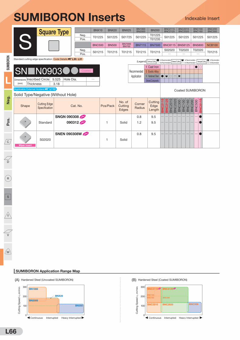
L66
SUMIBORON Application Range Map
Indexable Insert
300
200
100
0Heavy InterruptedContinuous Interrupted
BNX20
BN1000
BN350
BN2000
Cu
ttin
g S
peed
vc
( m/m
in) 300
200
100
0Heavy InterruptedContinuous Interrupted
BNC2010 BNC2020
BNC160
BNC100
BNC200
BNC2115 BNC2125
BNC300
Cu
ttin
g S
peed
vc
( m/m
in)
(A) Hardened Steel (Uncoated SUMIBORON) (B) Hardened Steel (Coated SUMIBORON)
SUMI
BORO
N
L
Neg
.P
os.
C
D
R
S
T
V
W
BNX10 BNX20 BNX25BN1000BN2000 BN350
BNC2115BNC2125
BNC2010BNC2020
BNC100BNC160
BNC200BNC300
Neg.T01225 S01225 S01725 S01225
T01225S01225 S01225 S01225 S01225
Pos. T01235
BNC500 BN500BN7000BN700 BN7115 BN7500 BNC8115 BNS8125 BNS800 NCB100
Neg.S01215 T01215 T01215 T01215 T01215
S02020 T02020 T02020T01215
Pos. Q Q Q
(Legend) Continuous Cutting : 1st Recommendation
General Cutting : 1st Recommendation
Interrupted Cutting : 1st Recommendation
: 2nd Recommendation : 2nd Recommendation : 2nd Recommendation
Recommended
Application
K Cast Iron
S Exotic Alloy
H Hardened Steel
Sintered Components
SUMIBORON Inserts
Solid Type/Negative (Without Hole)
Coated SUMIBORON
ShapeCutting Edge
SpecificationCat. No. Pcs/Pack
No. of
Cutting
Edges
Corner
Radius
Cutting
Edge
Length
BN
C2
11
5
BN
C2
12
5
BN
C2
01
0
BN
C2
02
0
BN
C3
00
BN
C1
00
BN
C1
60
BN
C2
00
BN
C5
00
BN
C8
11
5
Standard
SNGN 090308
1 Solid
0.8 9.5 Q Q Q Q Q Q Q Q Q D
SNGN 090312 1.2 9.5 Q Q Q Q Q Q Q Q Q D
Wiper Insert
S02020
SNEN 090308W
1 Solid
0.8 9.5 Q Q Q Q Q Q Q Q Q D
SSquare Type
SN N0903DD Coated
Dimensions
(mm)
Inscribed Circle 9.525 Hole Dia. QThickness 3.18
Standard cutting edge specification Code Details L30, L31
Applicable External Holders L112

L67
SUMIBORON Application Range Map
(D) Ductile Cast Iron
Indexable Insert
0 1.0 2.0 3.0
300
500
200
400
Depth of Cut ap (mm)
BNC500
BNC8115
BNS8125BN7000
Cutt
ing
Sp
eed
vc
( m/m
in)
100
200
300
Depth of Cut ap(mm)
Feed Rate f(mm/rev)
0 0.1
0.150.10.05 0.2 0.25 0.3
0.2 0.3 0.4 0.5
Finishing region
Roughing region
BN7500BN7115 BN7000
Cutt
ing
Sp
eed
vc
( m/m
in)
Depth of Cut ap(mm)
Feed Rate f(mm/rev)
0 0.1
0.150.10.05 0.2 0.25 0.3
0.2 0.3 0.4 0.5
100
200
300
Finishing region
Roughing region
BN7500BN7115 BN7000
Cutt
ing
Sp
eed
vc
( m/m
in)
0
100
200
300
0.05 0.10 0.15 0.20
Feed Rate f (mm/rev)
NCB100
Cutt
ing
Sp
eed
vc
( m/m
in)Finishing
regionRoughing region
0 1.0 2.0 3.0 4.0
1,000
2,000
2,500
500
1,500
Depth of Cut ap (mm)
BNS800
BN7000
BN500
BNC8115BNS8125
Cutt
ing
Sp
eed
vc
( m/m
in)
SUMIBORON
L
Neg
.P
os.
C
D
R
S
T
V
W
(G) Titanium Alloy(C) Gray Cast Iron (E) General Sintered Alloy (F) High-density Sintered Alloy
Recommended
Application
K Cast Iron
S Exotic Alloy
H Hardened Steel
Sintered Components
(Legend) Continuous Cutting : 1st Recommendation
General Cutting : 1st Recommendation
Interrupted Cutting : 1st Recommendation
: 2nd Recommendation : 2nd Recommendation : 2nd Recommendation
Recommended
Application
K Cast Iron
S Exotic Alloy
H Hardened Steel
Sintered Components
SUMIBORON Inserts
Solid Type/Negative (Without Hole)
Uncoated SUMIBORON
BIN
DE
RLE
SS
S
UM
IBO
RO
N
ShapeCutting Edge
SpecificationCat. No. Pcs/Pack
No. of
Cutting
Edges
Corner
Radius
Cutting
Edge
Length BN
X1
0
BN
X2
0
BN
X2
5
BN
10
00
BN
20
00
BN
35
0
BN
50
0
BN
70
00
BN
70
0
BN
71
15
BN
75
00
BN
S8125
BN
S8
00
NC
B1
00
Standard
SNGN 120308
1 Solid
0.8 12.7 Q Q Q Q Q Q Q Q Q Q Q D D Q
SNGN 120312 1.2 12.7 Q Q Q Q Q Q Q Q Q Q Q D D Q
Low Cutting Force
Sharp
Edge
SNGN 120308LF
1 Solid
0.8 12.7 Q Q Q Q Q Q Q Q Q Q Q D Q
SNGN 120312LF 1.2 12.7 Q Q Q Q Q Q Q Q Q Q Q D Q
SSquare Type
SNGN1203DD Uncoated
Dimensions
(mm)
Inscribed Circle 12.7 Hole Dia. QThickness 3.18
Solid Type/Negative (Without Hole)
Coated SUMIBORON
ShapeCutting Edge
SpecificationCat. No. Pcs/Pack
No. of
Cutting
Edges
Corner
Radius
Cutting
Edge
Length
BN
C2
11
5
BN
C2
12
5
BN
C2
01
0
BN
C2
02
0
BN
C3
00
BN
C1
00
BN
C1
60
BN
C2
00
BN
C5
00
BN
C8
11
5Standard
SNGN 120308
1 Solid
0.8 12.7 Q Q Q Q Q Q Q Q Q D
SNGN 120312 1.2 12.7 Q Q Q Q Q Q Q Q Q D
SNGN1203DD Coated
Dimensions
(mm)
Inscribed Circle 12.7 Hole Dia. QThickness 3.18
Applicable External Holders L112
Applicable External Holders L112
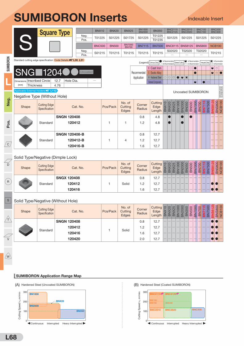
L68
SUMIBORON Application Range Map
Indexable Insert
300
200
100
0Heavy InterruptedContinuous Interrupted
BNX20
BN1000
BN350
BN2000
Cu
ttin
g S
peed
vc
( m/m
in) 300
200
100
0Heavy InterruptedContinuous Interrupted
BNC2010 BNC2020
BNC160
BNC100
BNC200
BNC2115 BNC2125
BNC300
Cu
ttin
g S
peed
vc
( m/m
in)
(A) Hardened Steel (Uncoated SUMIBORON) (B) Hardened Steel (Coated SUMIBORON)
SUMI
BORO
N
L
Neg
.P
os.
C
D
R
S
T
V
W
BNX10 BNX20 BNX25BN1000BN2000 BN350
BNC2115BNC2125
BNC2010BNC2020
BNC100BNC160
BNC200BNC300
Neg.T01225 S01225 S01725 S01225
T01225S01225 S01225 S01225 S01225
Pos. T01235
BNC500 BN500BN7000BN700 BN7115 BN7500 BNC8115 BNS8125 BNS800 NCB100
Neg.S01215 T01215 T01215 T01215 T01215
S02020 T02020 T02020T01215
Pos. Q Q Q
(Legend) Continuous Cutting : 1st Recommendation
General Cutting : 1st Recommendation
Interrupted Cutting : 1st Recommendation
: 2nd Recommendation : 2nd Recommendation : 2nd Recommendation
Recommended
Application
K Cast Iron
S Exotic Alloy
H Hardened Steel
Sintered Components
Solid Type/Negative (Without Hole)
ShapeCutting Edge
SpecificationCat. No. Pcs/Pack
No. of
Cutting
Edges
Corner
Radius
Cutting
Edge
Length BN
X1
0
BN
X2
0
BN
X2
5
BN
10
00
BN
20
00
BN
35
0
BN
50
0
BN
70
00
BN
70
0
BN
71
15
BN
75
00
BN
S8125
BN
S8
00
NC
B1
00
Standard
SNGN 120408
1 Solid
0.8 12.7 Q Q Q Q Q Q Q Q Q Q Q D D Q
SNGN 120412 1.2 12.7 Q Q Q Q Q Q Q Q Q Q Q D D Q
SNGN 120416 1.6 12.7 Q Q Q Q Q Q Q Q Q Q Q D D Q
SNGN 120420 2.0 12.7 Q Q Q Q Q Q Q Q Q Q Q D D Q
Solid Type/Negative (Dimple Lock)
ShapeCutting Edge
SpecificationCat. No. Pcs/Pack
No. of
Cutting
Edges
Corner
Radius
Cutting
Edge
Length BN
X1
0
BN
X2
0
BN
X2
5
BN
10
00
BN
20
00
BN
35
0
BN
50
0
BN
70
00
BN
70
0
BN
71
15
BN
75
00
BN
S8125
BN
S8
00
NC
B1
00
Standard
SNGX 120408
1 Solid
0.8 12.7 Q Q Q Q Q Q Q Q Q Q Q Q
SNGX 120412 1.2 12.7 Q Q Q Q Q Q Q Q Q Q Q D D Q
SNGX 120416 1.6 12.7 Q Q Q Q Q Q Q Q Q Q Q D D Q
SUMIBORON Inserts
Negative Type (Without Hole)
Uncoated SUMIBORON
BIN
DE
RLE
SS
S
UM
IBO
RO
N
ShapeCutting Edge
SpecificationCat. No. Pcs/Pack
No. of
Cutting
Edges
Corner
Radius
Cutting
Edge
Length BN
X1
0
BN
X2
0
BN
X2
5
BN
10
00
BN
20
00
BN
35
0
BN
50
0
BN
70
00
BN
70
0
BN
71
15
BN
75
00
BN
S8125
BN
S8
00
NC
B1
00
Standard
SNGN 120408
1 1
0.8 4.8 D D D Q Q Q
SNGN 120412 1.2 4.8 D D Q Q Q
Standard
SNGN 120408-B
1 4
0.8 12.7 Q Q Q
SNGN 120412-B 1.2 12.7 Q Q Q
SNGN 120416-B 1.6 12.7 Q Q Q
SSquare Type
SNG 1204DD Uncoated
Dimensions
(mm)
Inscribed Circle 12.7 Hole Dia. QThickness 4.76
Standard cutting edge specification Code Details L30, L31
Applicable External Holders L112

L69
SUMIBORON Application Range Map
(D) Ductile Cast Iron (G) Titanium Alloy
Indexable Insert
0 1.0 2.0 3.0
300
500
200
400
Depth of Cut ap (mm)
BNC500
BNC8115
BNS8125BN7000
Cuttin
g S
peed
vc ( m
/min
)
100
200
300
Depth of Cut ap(mm)
Feed Rate f(mm/rev)
0 0.1
0.150.10.05 0.2 0.25 0.3
0.2 0.3 0.4 0.5
Finishing region
Roughing region
BN7500BN7115 BN7000
Cuttin
g S
peed
vc ( m
/min
)
Depth of Cut ap(mm)
Feed Rate f(mm/rev)
0 0.1
0.150.10.05 0.2 0.25 0.3
0.2 0.3 0.4 0.5
100
200
300
Finishing region
Roughing region
BN7500BN7115 BN7000
Cuttin
g S
peed
vc ( m
/min
)
0
100
200
300
0.05 0.10 0.15 0.20
Feed Rate f (mm/rev)
NCB100
Cuttin
g S
peed
vc ( m
/min
)Finishing region
Roughing region
0 1.0 2.0 3.0 4.0
1,000
2,000
2,500
500
1,500
Depth of Cut ap (mm)
BNS800
BN7000
BN500
BNC8115BNS8125
Cuttin
g S
peed
vc ( m
/min
)
SUMIBORON
L
Neg
.P
os.
C
D
R
S
T
V
W
(C) Gray Cast Iron (E) General Sintered Alloy (F) High-density Sintered Alloy
Recommended
Application
K Cast Iron
S Exotic Alloy
H Hardened Steel
Sintered Components
(Legend) Continuous Cutting : 1st Recommendation
General Cutting : 1st Recommendation
Interrupted Cutting : 1st Recommendation
: 2nd Recommendation : 2nd Recommendation : 2nd Recommendation
Solid Type/Negative (Without Hole)
ShapeCutting Edge
SpecificationCat. No. Pcs/Pack
No. of
Cutting
Edges
Corner
Radius
Cutting
Edge
Length
BN
C2
11
5
BN
C2
12
5
BN
C2
01
0
BN
C2
02
0
BN
C3
00
BN
C1
00
BN
C1
60
BN
C2
00
BN
C5
00
BN
C8
11
5
Standard
SNGN 120408
1 Solid
0.8 12.7 Q Q Q Q Q Q Q Q Q D
SNGN 120412 1.2 12.7 Q Q Q Q Q Q Q Q Q D
SNGN 120416 1.6 12.7 Q Q Q Q Q Q Q Q Q D
SNGN 120420 2.0 12.7 Q Q Q Q Q Q Q Q Q D
SUMIBORON Inserts
SSquare Type
Solid Type/Negative (Dimple Lock)
Coated SUMIBORON
ShapeCutting Edge
SpecificationCat. No. Pcs/Pack
No. of
Cutting
Edges
Corner
Radius
Cutting
Edge
Length
BN
C2
11
5
BN
C2
12
5
BN
C2
01
0
BN
C2
02
0
BN
C3
00
BN
C1
00
BN
C1
60
BN
C2
00
BN
C5
00
BN
C8
11
5
Standard
SNGX 120412
1 Solid
1.2 12.7 Q Q Q Q Q Q Q Q Q D
SNGX 120416 1.6 12.7 Q Q Q Q Q Q Q Q Q D
SNG 1204DD Coated
Dimensions
(mm)
Inscribed Circle 12.7 Hole Dia. QThickness 4.76
Applicable External Holders L112
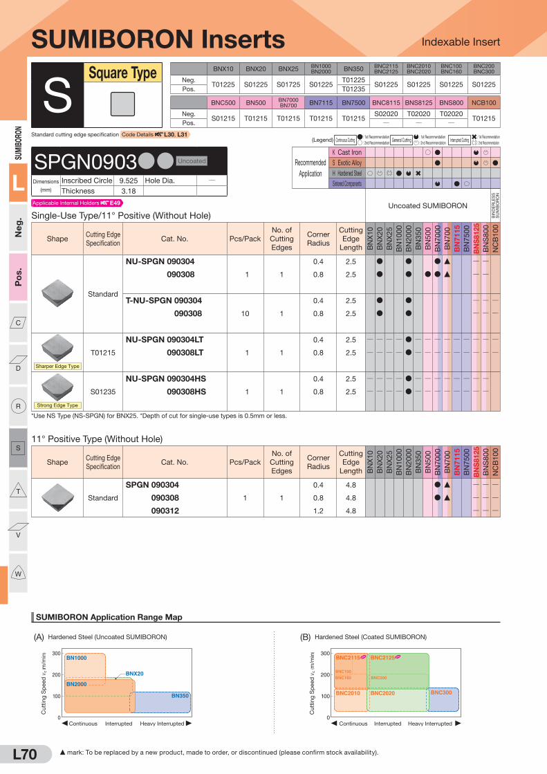
L70
SUMIBORON Application Range Map
Indexable Insert
300
200
100
0Heavy InterruptedContinuous Interrupted
BNX20
BN1000
BN350
BN2000
Cu
ttin
g S
peed
vc
( m/m
in) 300
200
100
0Heavy InterruptedContinuous Interrupted
BNC2010 BNC2020
BNC160
BNC100
BNC200
BNC2115 BNC2125
BNC300
Cu
ttin
g S
peed
vc
( m/m
in)
(A) Hardened Steel (Uncoated SUMIBORON) (B) Hardened Steel (Coated SUMIBORON)
SUMI
BORO
N
L
Neg
.P
os.
C
D
R
S
T
V
W
BNX10 BNX20 BNX25BN1000BN2000 BN350
BNC2115BNC2125
BNC2010BNC2020
BNC100BNC160
BNC200BNC300
Neg.T01225 S01225 S01725 S01225
T01225S01225 S01225 S01225 S01225
Pos. T01235
BNC500 BN500BN7000BN700 BN7115 BN7500 BNC8115 BNS8125 BNS800 NCB100
Neg.S01215 T01215 T01215 T01215 T01215
S02020 T02020 T02020T01215
Pos. Q Q Q
(Legend) Continuous Cutting : 1st Recommendation
General Cutting : 1st Recommendation
Interrupted Cutting : 1st Recommendation
: 2nd Recommendation : 2nd Recommendation : 2nd Recommendation
Recommended
Application
K Cast Iron
S Exotic Alloy
H Hardened Steel
Sintered Components
11° Positive Type (Without Hole)
ShapeCutting Edge
SpecificationCat. No. Pcs/Pack
No. of
Cutting
Edges
Corner
Radius
Cutting
Edge
Length BN
X1
0
BN
X2
0
BN
X2
5
BN
10
00
BN
20
00
BN
35
0
BN
50
0
BN
70
00
BN
70
0
BN
71
15
BN
75
00
BN
S8125
BN
S8
00
NC
B1
00
Standard
SPGN 090304
1 1
0.4 4.8 D F Q Q Q
SPGN 090308 0.8 4.8 D F Q Q Q
SPGN 090312 1.2 4.8 Q Q Q
SUMIBORON Inserts
Single-Use Type/11° Positive (Without Hole)
Uncoated SUMIBORON
BIN
DE
RLE
SS
S
UM
IBO
RO
N
ShapeCutting Edge
SpecificationCat. No. Pcs/Pack
No. of
Cutting
Edges
Corner
Radius
Cutting
Edge
Length BN
X1
0
BN
X2
0
BN
X2
5
BN
10
00
BN
20
00
BN
35
0
BN
50
0
BN
70
00
BN
70
0
BN
71
15
BN
75
00
BN
S8125
BN
S8
00
NC
B1
00
Standard
NU-SPGN 090304
1 1
0.4 2.5 D D D F Q Q
NU-SPGN 090308 0.8 2.5 D D D D F Q Q
T-NU-SPGN 090304
10 1
0.4 2.5 D D Q Q Q
T-NU-SPGN 090308 0.8 2.5 D D Q Q Q
Sharper Edge Type
T01215
NU-SPGN 090304LT
1 1
0.4 2.5 Q Q Q Q D Q Q Q Q Q Q Q Q Q
NU-SPGN 090308LT 0.8 2.5 Q Q Q Q D Q Q Q Q Q Q Q Q Q
Strong Edge Type
S01235
NU-SPGN 090304HS
1 1
0.4 2.5 Q Q Q Q D Q Q Q Q Q Q Q Q
NU-SPGN 090308HS 0.8 2.5 Q Q Q Q D Q Q Q Q Q Q Q Q
*Use NS Type (NS-SPGN) for BNX25. *Depth of cut for single-use types is 0.5mm or less.
SSquare Type
SPGN0903DD Uncoated
Dimensions
(mm)
Inscribed Circle 9.525 Hole Dia. QThickness 3.18
Standard cutting edge specification Code Details L30, L31
Applicable Internal Holders E49
F mark: To be replaced by a new product, made to order, or discontinued (please confirm stock availability).
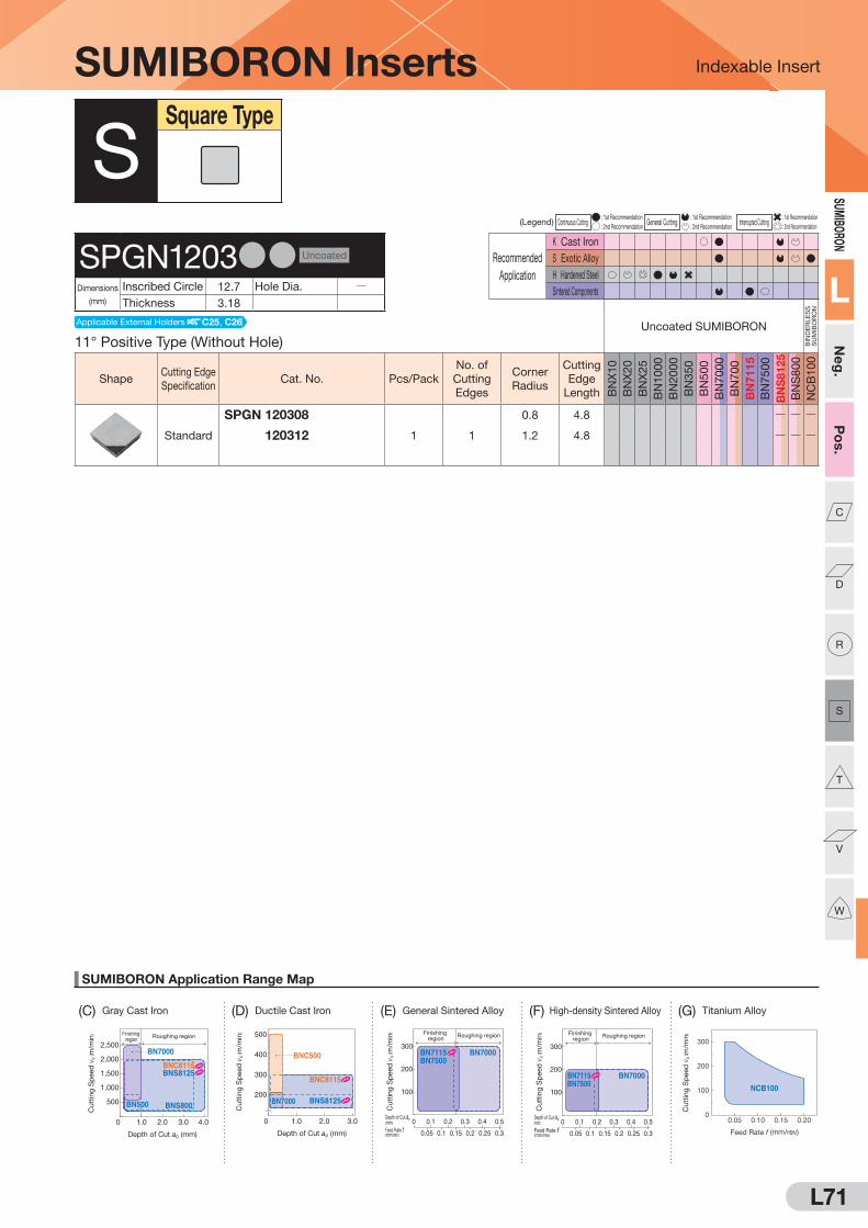
L71
SUMIBORON Application Range Map
(D) Ductile Cast Iron (G) Titanium Alloy
Indexable Insert
0 1.0 2.0 3.0
300
500
200
400
Depth of Cut ap (mm)
BNC500
BNC8115
BNS8125BN7000
Cutt
ing
Sp
eed
vc
( m/m
in)
100
200
300
Depth of Cut ap(mm)
Feed Rate f(mm/rev)
0 0.1
0.150.10.05 0.2 0.25 0.3
0.2 0.3 0.4 0.5
Finishing region
Roughing region
BN7500BN7115 BN7000
Cutt
ing
Sp
eed
vc
( m/m
in)
Depth of Cut ap(mm)
Feed Rate f(mm/rev)
0 0.1
0.150.10.05 0.2 0.25 0.3
0.2 0.3 0.4 0.5
100
200
300
Finishing region
Roughing region
BN7500BN7115 BN7000
Cutt
ing
Sp
eed
vc
( m/m
in)
0
100
200
300
0.05 0.10 0.15 0.20
Feed Rate f (mm/rev)
NCB100
Cutt
ing
Sp
eed
vc
( m/m
in)Finishing
regionRoughing region
0 1.0 2.0 3.0 4.0
1,000
2,000
2,500
500
1,500
Depth of Cut ap (mm)
BNS800
BN7000
BN500
BNC8115BNS8125
Cutt
ing
Sp
eed
vc
( m/m
in)
SUMIBORON
L
Neg
.P
os.
C
D
R
S
T
V
W
(C) Gray Cast Iron (E) General Sintered Alloy (F) High-density Sintered Alloy
(Legend) Continuous Cutting : 1st Recommendation
General Cutting : 1st Recommendation
Interrupted Cutting : 1st Recommendation
: 2nd Recommendation : 2nd Recommendation : 2nd Recommendation
Recommended
Application
K Cast Iron
S Exotic Alloy
H Hardened Steel
Sintered Components
SUMIBORON Inserts
11° Positive Type (Without Hole)
Uncoated SUMIBORON
BIN
DE
RLE
SS
S
UM
IBO
RO
N
ShapeCutting Edge
SpecificationCat. No. Pcs/Pack
No. of
Cutting
Edges
Corner
Radius
Cutting
Edge
Length BN
X1
0
BN
X2
0
BN
X2
5
BN
10
00
BN
20
00
BN
35
0
BN
50
0
BN
70
00
BN
70
0
BN
71
15
BN
75
00
BN
S8125
BN
S8
00
NC
B1
00
Standard
SPGN 120308
1 1
0.8 4.8 Q Q Q
SPGN 120312 1.2 4.8 Q Q Q
SSquare Type
SPGN1203DD Uncoated
Dimensions
(mm)
Inscribed Circle 12.7 Hole Dia. QThickness 3.18
Applicable External Holders C25, C26

L72
SUMIBORON Application Range Map
Indexable Insert
300
200
100
0Heavy InterruptedContinuous Interrupted
BNX20
BN1000
BN350
BN2000
Cu
ttin
g S
peed
vc
( m/m
in) 300
200
100
0Heavy InterruptedContinuous Interrupted
BNC2010 BNC2020
BNC160
BNC100
BNC200
BNC2115 BNC2125
BNC300
Cu
ttin
g S
peed
vc
( m/m
in)
(A) Hardened Steel (Uncoated SUMIBORON) (B) Hardened Steel (Coated SUMIBORON)
SUMI
BORO
N
L
Neg
.P
os.
C
D
R
S
T
V
W
F mark: To be replaced by a new product, made to order, or discontinued (please confirm stock availability).
BNX10 BNX20 BNX25BN1000BN2000 BN350
BNC2115BNC2125
BNC2010BNC2020
BNC100BNC160
BNC200BNC300
Neg.T01225 S01225 S01725 S01225
T01225S01225 S01225 S01225 S01225
Pos. T01235
BNC500 BN500BN7000BN700 BN7115 BN7500 BNC8115 BNS8125 BNS800 NCB100
Neg.S01215 T01215 T01215 T01215 T01215
S02020 T02020 T02020T01215
Pos. Q Q Q
(Legend) Continuous Cutting : 1st Recommendation
General Cutting : 1st Recommendation
Interrupted Cutting : 1st Recommendation
: 2nd Recommendation : 2nd Recommendation : 2nd Recommendation
Recommended
Application
K Cast Iron
S Exotic Alloy
H Hardened Steel
Sintered Components
Single-Use Type/Negative (With Hole)
Uncoated SUMIBORON
BIN
DE
RLE
SS
S
UM
IBO
RO
N
ShapeCutting Edge
SpecificationCat. No. Pcs/Pack
No. of
Cutting
Edges
Corner
Radius
Cutting
Edge
Length BN
X1
0
BN
X2
0
BN
X2
5
BN
10
00
BN
20
00
BN
35
0
BN
50
0
BN
70
00
BN
70
0
BN
71
15
BN
75
00
BN
S8125
BN
S8
00
NC
B1
00
Standard
NU-TNMA 160401
1 1
0.1 2.5 Q D Q Q QNU-TNMA 160402 0.2 2.4 Q D Q Q QNU-TNMA 160404 0.4 2.3 D D Q D D D D D F Q Q QNU-TNMA 160408 0.8 2.0 D D Q D D D D D F Q Q QNU-TNMA 160412 1.2 2.0 D Q D D D F Q Q QT-NU-TNMA 160401
10 1
0.1 2.5 Q Q Q QT-NU-TNMA 160402 0.2 2.4 Q Q Q QT-NU-TNMA 160404 0.4 2.3 D D Q D D D D Q Q QT-NU-TNMA 160408 0.8 2.0 D D Q D D D D Q Q QT-NU-TNMA 160412 1.2 2.0 D Q Q Q Q
Standard
NS-TNMA 160404
1 1
0.4 2.3 Q Q F Q Q Q Q Q Q Q Q Q Q QNS-TNMA 160408 0.8 2.0 Q Q F Q Q Q Q Q Q Q Q Q Q QNS-TNMA 160412 1.2 2.0 Q Q Q Q Q Q Q Q Q Q Q Q QT-NS-TNMA 160404
10 1
0.4 2.3 Q Q F Q Q Q Q Q Q Q Q Q Q QT-NS-TNMA 160408 0.8 2.0 Q Q F Q Q Q Q Q Q Q Q Q Q QT-NS-TNMA 160412 1.2 2.0 Q Q Q Q Q Q Q Q Q Q Q Q Q
*Depth of cut for single-use types is 0.5mm or less.
Multi-Cornered Single-Use Type/Negative (With Hole)
ShapeCutting Edge
SpecificationCat. No. Pcs/Pack
No. of
Cutting
Edges
Corner
Radius
Cutting
Edge
Length BN
X1
0
BN
X2
0
BN
X2
5
BN
10
00
BN
20
00
BN
35
0
BN
50
0
BN
70
00
BN
70
0
BN
71
15
BN
75
00
BN
S8125
BN
S8
00
NC
B1
00
Standard
3NU-TNGA 160404
1 3
0.4 2.3 D Q D D D D F D D Q Q3NU-TNGA 160408 0.8 2.0 D Q D D D D F D D Q Q3NU-TNGA 160412 1.2 2.0 D Q D D D D D Q QT-3NU-TNGA 160404
10 3
0.4 2.3 D Q D D F D D Q Q QT-3NU-TNGA 160408 0.8 2.0 D Q D D D F Q Q QT-3NU-TNGA 160412 1.2 2.0 D Q D Q Q Q
Standard
3NS-TNGA 160404
1 3
0.4 2.3 Q Q F Q Q Q Q Q Q Q Q Q Q Q3NS-TNGA 160408 0.8 2.0 Q Q F Q Q Q Q Q Q Q Q Q Q Q3NS-TNGA 160412 1.2 2.0 Q Q Q Q Q Q Q Q Q Q Q Q QT-3NS-TNGA 160404
10 3
0.4 2.3 Q Q F Q Q Q Q Q Q Q Q Q Q QT-3NS-TNGA 160408 0.8 2.0 Q Q F Q Q Q Q Q Q Q Q Q Q QT-3NS-TNGA 160412 1.2 2.0 Q Q Q Q Q Q Q Q Q Q Q Q Q
*Depth of cut for single-use types is 0.5mm or less.
SUMIBORON Inserts
TTriangular Type
TN 1604DD Uncoated
Dimensions
(mm)
Inscribed Circle 9.525 Hole Dia. 3.81
Thickness 4.76
Applicable Internal Holders E15, E61 to E63Applicable External Holders C27 to C33, D16, D20
Standard cutting edge specification Code Details L30, L31

L73
SUMIBORON Application Range Map
(D) Ductile Cast Iron
Indexable Insert
0 1.0 2.0 3.0
300
500
200
400
Depth of Cut ap (mm)
BNC500
BNC8115
BNS8125BN7000
Cutt
ing
Sp
eed
vc
( m/m
in)
100
200
300
Depth of Cut ap(mm)
Feed Rate f(mm/rev)
0 0.1
0.150.10.05 0.2 0.25 0.3
0.2 0.3 0.4 0.5
Finishing region
Roughing region
BN7500BN7115 BN7000
Cutt
ing
Sp
eed
vc
( m/m
in)
Depth of Cut ap(mm)
Feed Rate f(mm/rev)
0 0.1
0.150.10.05 0.2 0.25 0.3
0.2 0.3 0.4 0.5
100
200
300
Finishing region
Roughing region
BN7500BN7115 BN7000
Cutt
ing
Sp
eed
vc
( m/m
in)
0
100
200
300
0.05 0.10 0.15 0.20
Feed Rate f (mm/rev)
NCB100
Cutt
ing
Sp
eed
vc
( m/m
in)Finishing
regionRoughing region
0 1.0 2.0 3.0 4.0
1,000
2,000
2,500
500
1,500
Depth of Cut ap (mm)
BNS800
BN7000
BN500
BNC8115BNS8125
Cutt
ing
Sp
eed
vc
( m/m
in)
SUMIBORON
L
Neg
.P
os.
C
D
R
S
T
V
W
(G) Titanium Alloy(C) Gray Cast Iron (E) General Sintered Alloy (F) High-density Sintered Alloy
F mark: To be replaced by a new product, made to order, or discontinued (please confirm stock availability).
(Legend) Continuous Cutting : 1st Recommendation
General Cutting : 1st Recommendation
Interrupted Cutting : 1st Recommendation
: 2nd Recommendation : 2nd Recommendation : 2nd Recommendation
Recommended
Application
K Cast Iron
S Exotic Alloy
H Hardened Steel
Sintered Components
SUMIBORON Inserts
Multi-Cornered Single-Use Type/Negative (With Hole)
Uncoated SUMIBORON
BIN
DE
RLE
SS
S
UM
IBO
RO
N
ShapeCutting Edge
SpecificationCat. No. Pcs/Pack
No. of
Cutting
Edges
Corner
Radius
Cutting
Edge
Length BN
X1
0
BN
X2
0
BN
X2
5
BN
10
00
BN
20
00
BN
35
0
BN
50
0
BN
70
00
BN
70
0
BN
71
15
BN
75
00
BN
S8125
BN
S8
00
NC
B1
00
BREAK MASTER
S00535
3NU-TNGM 160404N-LV
1 3
0.4 2.3 Q Q Q Q D Q Q Q Q Q Q Q Q Q
3NU-TNGM 160408N-LV 0.8 2.0 Q Q Q Q D Q Q Q Q Q Q Q Q Q
3NU-TNGM 160412N-LV 1.2 2.0 Q Q Q Q D Q Q Q Q Q Q Q Q Q
Low Cutting Force
Sharp
Edge
3NU-TNGA 160404LF
1 3
0.4 2.3 Q Q Q Q Q Q Q D F D D Q Q
3NU-TNGA 160408LF 0.8 2.0 Q Q Q Q Q Q Q D F D D Q Q
3NU-TNGA 160412LF 1.2 2.0 Q Q Q Q Q Q Q Q Q
Low Cutting Force
Honing
3NU-TNGA 160404LE
1 3
0.4 2.3 Q Q Q Q Q Q Q Q D D Q Q
3NU-TNGA 160408LE 0.8 2.0 Q Q Q Q Q Q Q Q D D Q Q
Sharper Edge Type
T01215
3NU-TNGA 160404LT
1 3
0.4 2.3 Q Q Q Q D Q Q Q Q Q Q Q Q Q
3NU-TNGA 160408LT 0.8 2.0 Q Q Q Q D Q Q Q Q Q Q Q Q Q
3NU-TNGA 160412LT 1.2 2.0 Q Q Q Q D Q Q Q Q Q Q Q Q Q
General-purpose Type for Continuous Cutting
BN7115 S00515
BN7500 S00715
3NU-TNGA 160404LS
1 3
0.4 2.3 Q Q Q Q Q Q Q Q D D Q Q
3NU-TNGA 160408LS 0.8 2.0 Q Q Q Q Q Q Q Q D Q Q
Strong Edge Type
T01235
3NU-TNGA 160404HT
1 3
0.4 2.3 Q Q Q Q Q D Q Q Q Q Q Q Q
3NU-TNGA 160408HT 0.8 2.0 Q Q Q Q Q D Q Q Q Q Q Q Q
3NU-TNGA 160412HT 1.2 2.0 Q Q Q Q Q D Q Q Q Q Q Q Q
Strong Edge Type
BN2000 S01235
BN7000 S01225
BN700 S01225
BN7500 S00525
3NU-TNGA 160404HS
1 3
0.4 2.3 Q Q Q Q D Q Q D F D D Q Q
3NU-TNGA 160408HS 0.8 2.0 Q Q Q Q D Q Q D F D Q Q
3NU-TNGA 160412HS 1.2 2.0 Q Q Q Q D Q Q Q Q*Depth of cut for single-use types is 0.5mm or less.
TN 1604DD Uncoated
Dimensions
(mm)
Inscribed Circle 9.525 Hole Dia. 3.81
Thickness 4.76
Applicable Internal Holders E15, E61 to E63Applicable External Holders C27 to C33, D16, D20
TTriangular Type

L74
SUMIBORON Application Range Map
Indexable Insert
300
200
100
0Heavy InterruptedContinuous Interrupted
BNX20
BN1000
BN350
BN2000
Cu
ttin
g S
peed
vc
( m/m
in) 300
200
100
0Heavy InterruptedContinuous Interrupted
BNC2010 BNC2020
BNC160
BNC100
BNC200
BNC2115 BNC2125
BNC300
Cu
ttin
g S
peed
vc
( m/m
in)
(A) Hardened Steel (Uncoated SUMIBORON) (B) Hardened Steel (Coated SUMIBORON)
SUMIBORO
N
L
Neg.
Pos.
C
D
R
S
T
V
W
F mark: To be replaced by a new product, made to order, or discontinued (please confirm stock availability).
BNX10 BNX20 BNX25BN1000BN2000 BN350
BNC2115BNC2125
BNC2010BNC2020
BNC100BNC160
BNC200BNC300
Neg.T01225 S01225 S01725 S01225
T01225S01225 S01225 S01225 S01225
Pos. T01235
BNC500 BN500BN7000BN700 BN7115 BN7500 BNC8115 BNS8125 BNS800 NCB100
Neg.S01215 T01215 T01215 T01215 T01215
S02020 T02020 T02020T01215
Pos. Q Q Q
(Legend) Continuous Cutting : 1st Recommendation
General Cutting : 1st Recommendation
Interrupted Cutting : 1st Recommendation
: 2nd Recommendation : 2nd Recommendation : 2nd Recommendation
Recommended
Application
K Cast Iron
S Exotic Alloy
H Hardened Steel
Sintered Components
Solid Type/Negative (With Hole)
ShapeCutting Edge
SpecificationCat. No. Pcs/Pack
No. of
Cutting
Edges
Corner
Radius
Cutting
Edge
Length BN
X1
0
BN
X2
0
BN
X2
5
BN
10
00
BN
20
00
BN
35
0
BN
50
0
BN
70
00
BN
70
0
BN
71
15
BN
75
00
BN
S8125
BN
S8
00
NC
B1
00
Standard
TNGA 160408
1 Solid
0.8 15.3 Q Q Q Q Q Q Q Q Q Q Q Q D Q
TNGA 160412 1.2 15.7 Q Q Q Q Q Q Q Q Q Q Q Q D Q
SUMIBORON Inserts
Negative Type (With Hole)
ShapeCutting Edge
SpecificationCat. No. Pcs/Pack
No. of
Cutting
Edges
Corner
Radius
Cutting
Edge
Length BN
X1
0
BN
X2
0
BN
X2
5
BN
10
00
BN
20
00
BN
35
0
BN
50
0
BN
70
00
BN
70
0
BN
71
15
BN
75
00
BN
S8125
BN
S8
00
NC
B1
00
Standard
TNMA 160402
1 1
0.2 3.6 D D Q Q Q
TNMA 160404 0.4 3.5 D D Q Q Q
TNMA 160408 0.8 3.2 D D D D F Q Q Q
TNMA 160412 1.2 2.9 D D D D F Q Q Q
Multi-Cornered Single-Use Type/Negative (With Hole)
Uncoated SUMIBORON
BIN
DE
RLE
SS
S
UM
IBO
RO
N
ShapeCutting Edge
SpecificationCat. No. Pcs/Pack
No. of
Cutting
Edges
Corner
Radius
Cutting
Edge
Length BN
X1
0
BN
X2
0
BN
X2
5
BN
10
00
BN
20
00
BN
35
0
BN
50
0
BN
70
00
BN
70
0
BN
71
15
BN
75
00
BN
S8125
BN
S8
00
NC
B1
00
Strong Edge Type
S01225
3NU-TNGA 160404US
1 3
0.4 2.3 Q Q Q Q Q Q Q Q Q D Q Q Q Q
*Depth of cut for single-use types is 0.5mm or less.
TTriangular Type
TN 1604DD Uncoated
Dimensions
(mm)
Inscribed Circle 9.525 Hole Dia. 3.81
Thickness 4.76
Standard cutting edge specification Code Details L30, L31
Applicable Internal Holders E15, E61 to E63Applicable External Holders C27 to C33, D16, D20

L75
SUMIBORON Application Range Map
(D) Ductile Cast Iron (G) Titanium Alloy
Indexable Insert
0 1.0 2.0 3.0
300
500
200
400
Depth of Cut ap (mm)
BNC500
BNC8115
BNS8125BN7000
Cuttin
g S
peed
vc ( m
/min
)
100
200
300
Depth of Cut ap(mm)
Feed Rate f(mm/rev)
0 0.1
0.150.10.05 0.2 0.25 0.3
0.2 0.3 0.4 0.5
Finishing region
Roughing region
BN7500BN7115 BN7000
Cuttin
g S
peed
vc ( m
/min
)
Depth of Cut ap(mm)
Feed Rate f(mm/rev)
0 0.1
0.150.10.05 0.2 0.25 0.3
0.2 0.3 0.4 0.5
100
200
300
Finishing region
Roughing region
BN7500BN7115 BN7000
Cuttin
g S
peed
vc ( m
/min
)
0
100
200
300
0.05 0.10 0.15 0.20
Feed Rate f (mm/rev)
NCB100
Cuttin
g S
peed
vc ( m
/min
)Finishing region
Roughing region
0 1.0 2.0 3.0 4.0
1,000
2,000
2,500
500
1,500
Depth of Cut ap (mm)
BNS800
BN7000
BN500
BNC8115BNS8125
Cuttin
g S
peed
vc ( m
/min
)
SUMIBO
RON
L
Neg.
Pos.
C
D
R
S
T
V
W
(C) Gray Cast Iron (E) General Sintered Alloy (F) High-density Sintered Alloy
S mark: Stock or planned stock (please confirm stock availability)
(Legend) Continuous Cutting : 1st Recommendation
General Cutting : 1st Recommendation
Interrupted Cutting : 1st Recommendation
: 2nd Recommendation : 2nd Recommendation : 2nd Recommendation
Recommended
Application
K Cast Iron
S Exotic Alloy
H Hardened Steel
Sintered Components
SUMIBORON Inserts
Multi-Cornered Single-Use Type/Negative (With Hole)
Coated SUMIBORON
ShapeCutting Edge
SpecificationCat. No. Pcs/Pack
No. of
Cutting
Edges
Corner
Radius
Cutting
Edge
Length
BN
C2
11
5
BN
C2
12
5
BN
C2
01
0
BN
C2
02
0
BN
C3
00
BN
C1
00
BN
C1
60
BN
C2
00
BN
C5
00
BN
C8
11
5
Standard
3NC-TNGA 160404
1 3
0.4 2.3 S D D D Q
3NC-TNGA 160408 0.8 2.0 S D D D Q
3NC-TNGA 160412 1.2 2.0 S D D Q
3NC-TNGA 160416*1
1.6 3.3 D D D D D Q
3NC-TNGA 160420*1
2.0 3.0 D D D D D Q
3NC-TNGA 160424*1
2.4 2.7 D D D D D Q
Standard
6NC-TNGA 160402
1 6
0.2 2.4 S S D D Q
6NC-TNGA 160404 0.4 2.3 S S D D D D D D D Q
6NC-TNGA 160408 0.8 2.0 S S D D D D D D D Q
6NC-TNGA 160412 1.2 2.0 S S D D D D D D Q
6NC-TNGA 160416*1
1.6 3.3 S S D D D D D Q
6NC-TNGA 160420*1
2.0 3.0 S S D D D D D Q
6NC-TNGA 160424*1
2.4 2.7 S S D D D D D Q
BREAK MASTER
Honing
6NC-TNGG 160404N-FV
1 6
0.4 2.3 S S D D Q Q D D Q Q
6NC-TNGG 160408N-FV 0.8 2.0 S S D D Q Q D D Q Q
6NC-TNGG 160412N-FV 1.2 2.0 S S D D Q Q D D Q Q
BREAK MASTER
S00535
6NC-TNGG 160404N-LV
1 6
0.4 2.3 S S D D Q Q D D Q Q
6NC-TNGG 160408N-LV 0.8 2.0 S S D D Q Q D D Q Q
6NC-TNGG 160412N-LV 1.2 2.0 S S D D Q Q D D Q Q
BREAK MASTER
S01235
6NC-TNGG 160404N-SV
1 6
0.4 2.3 Q Q Q Q
6NC-TNGG 160408N-SV 0.8 2.0 S S D D Q Q D D Q Q
6NC-TNGG 160412N-SV 1.2 2.0 S S D D Q Q D D Q Q
Low Cutting Force
Honing
3NC-TNGA 160404LE
1 3
0.4 2.3 Q Q D Q Q Q Q Q Q Q
3NC-TNGA 160408LE 0.8 2.0 Q Q D Q Q Q Q Q Q Q
3NC-TNGA 160412LE 1.2 2.0 Q Q D Q Q Q Q Q Q Q
Sharper Edge Type
T00515
3NC-TNGA 160402LT
1 3
0.2 2.4 Q Q Q D Q Q Q Q Q Q
3NC-TNGA 160404LT 0.4 2.3 Q Q Q D Q Q Q Q Q Q
3NC-TNGA 160408LT 0.8 2.0 Q Q Q D Q Q Q Q Q Q
3NC-TNGA 160412LT 1.2 2.0 Q Q Q D Q Q Q Q Q Q
*1 For use with the SUMIBORON Special Holders for High-Efficiency Machining shown on page L118.
TTriangular Type
TNG 1604DD Coated
Dimensions
(mm)
Inscribed Circle 9.525 Hole Dia. 3.81
Thickness 4.76
Applicable Internal Holders E15, E61 to E63Applicable External Holders C27 to C33, D16, D20
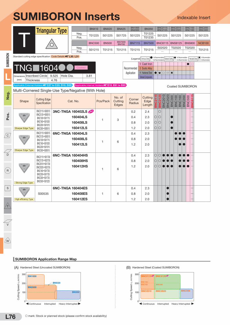
L76
SUMIBORON Application Range Map
Indexable Insert
300
200
100
0Heavy InterruptedContinuous Interrupted
BNX20
BN1000
BN350
BN2000
Cu
ttin
g S
peed
vc
( m/m
in) 300
200
100
0Heavy InterruptedContinuous Interrupted
BNC2010 BNC2020
BNC160
BNC100
BNC200
BNC2115 BNC2125
BNC300
Cu
ttin
g S
peed
vc
( m/m
in)
(A) Hardened Steel (Uncoated SUMIBORON) (B) Hardened Steel (Coated SUMIBORON)
SUMIBORO
N
L
Neg.
Pos.
C
D
R
S
T
V
W
BNX10 BNX20 BNX25BN1000BN2000 BN350
BNC2115BNC2125
BNC2010BNC2020
BNC100BNC160
BNC200BNC300
Neg.T01225 S01225 S01725 S01225
T01225S01225 S01225 S01225 S01225
Pos. T01235
BNC500 BN500BN7000BN700 BN7115 BN7500 BNC8115 BNS8125 BNS800 NCB100
Neg.S01215 T01215 T01215 T01215 T01215
S02020 T02020 T02020T01215
Pos. Q Q Q
(Legend) Continuous Cutting : 1st Recommendation
General Cutting : 1st Recommendation
Interrupted Cutting : 1st Recommendation
: 2nd Recommendation : 2nd Recommendation : 2nd Recommendation
Recommended
Application
K Cast Iron
S Exotic Alloy
H Hardened Steel
Sintered Components
S mark: Stock or planned stock (please confirm stock availability)
SUMIBORON Inserts
Multi-Cornered Single-Use Type/Negative (With Hole)
Coated SUMIBORON
ShapeCutting Edge
SpecificationCat. No. Pcs/Pack
No. of
Cutting
Edges
Corner
Radius
Cutting
Edge
Length
BN
C2
11
5
BN
C2
12
5
BN
C2
01
0
BN
C2
02
0
BN
C3
00
BN
C1
00
BN
C1
60
BN
C2
00
BN
C5
00
BN
C8
11
5
Sharper Edge Type
BNC2115 S00515
BNC2125 S00515
BNC100 S01715
BNC160 S01020
BNC200 S01015
BNC300 S00515
3NC-TNGA 160402LS
1 3
0.2 2.4 S Q
3NC-TNGA 160404LS 0.4 2.3 S S D Q
3NC-TNGA 160408LS 0.8 2.0 S S D Q
3NC-TNGA 160412LS 1.2 2.0 S S D Q
Sharper Edge Type
BNC2115 S00515
BNC2125 S00515
BNC100 S01715
BNC160 S01020
BNC200 S01015
BNC300 S00515
6NC-TNGA 160404LS
1 6
0.4 2.3 D D D Q
6NC-TNGA 160408LS 0.8 2.0 D D D Q
6NC-TNGA 160412LS 1.2 2.0 D D Q
Strong Edge Type
BNC2115 S01730
BNC2125 S02735
BNC2010 S01730
BNC2020 S02735
BNC160 S01730
BNC200 S01735
BNC300 S01735
BNC500 S01225
6NC-TNGA 160404HS
1 6
0.4 2.3 S S D D D D D D Q
6NC-TNGA 160408HS 0.8 2.0 S S D D D D D D Q
6NC-TNGA 160412HS 1.2 2.0 S S D D D D D D Q
High-efficiency Type
S00535
6NC-TNGA 160404ES
1 6
0.4 2.3 D Q
6NC-TNGA 160408ES 0.8 2.0 D Q
6NC-TNGA 160412ES 1.2 2.0 D Q
TTriangular Type
TNG 1604DD Coated
Dimensions
(mm)
Inscribed Circle 9.525 Hole Dia. 3.81
Thickness 4.76
Standard cutting edge specification Code Details L30, L31
Applicable Internal Holders E15, E61 to E63Applicable External Holders C27 to C33, D16, D20

L77
SUMIBORON Application Range Map
(D) Ductile Cast Iron (G) Titanium Alloy
Indexable Insert
0 1.0 2.0 3.0
300
500
200
400
Depth of Cut ap (mm)
BNC500
BNC8115
BNS8125BN7000
Cutt
ing
Sp
eed
vc
( m/m
in)
100
200
300
Depth of Cut ap(mm)
Feed Rate f(mm/rev)
0 0.1
0.150.10.05 0.2 0.25 0.3
0.2 0.3 0.4 0.5
Finishing region
Roughing region
BN7500BN7115 BN7000
Cutt
ing
Sp
eed
vc
( m/m
in)
Depth of Cut ap(mm)
Feed Rate f(mm/rev)
0 0.1
0.150.10.05 0.2 0.25 0.3
0.2 0.3 0.4 0.5
100
200
300
Finishing region
Roughing region
BN7500BN7115 BN7000
Cutt
ing
Sp
eed
vc
( m/m
in)
0
100
200
300
0.05 0.10 0.15 0.20
Feed Rate f (mm/rev)
NCB100
Cutt
ing
Sp
eed
vc
( m/m
in)Finishing
regionRoughing region
0 1.0 2.0 3.0 4.0
1,000
2,000
2,500
500
1,500
Depth of Cut ap (mm)
BNS800
BN7000
BN500
BNC8115BNS8125
Cutt
ing
Sp
eed
vc
( m/m
in)
SUMIBO
RON
L
Neg.
Pos.
C
D
R
S
T
V
W
(C) Gray Cast Iron (E) General Sintered Alloy (F) High-density Sintered Alloy
Recommended
Application
K Cast Iron
S Exotic Alloy
H Hardened Steel
Sintered Components
(Legend) Continuous Cutting : 1st Recommendation
General Cutting : 1st Recommendation
Interrupted Cutting : 1st Recommendation
: 2nd Recommendation : 2nd Recommendation : 2nd Recommendation
Recommended
Application
K Cast Iron
S Exotic Alloy
H Hardened Steel
Sintered Components
Recommended
Application
K Cast Iron
S Exotic Alloy
H Hardened Steel
Sintered Components
SUMIBORON Inserts
Solid Type/Negative (Without Hole)
Uncoated SUMIBORON
BIN
DE
RLE
SS
S
UM
IBO
RO
N
ShapeCutting Edge
SpecificationCat. No. Pcs/Pack
No. of
Cutting
Edges
Corner
Radius
Cutting
Edge
Length BN
X1
0
BN
X2
0
BN
X2
5
BN
10
00
BN
20
00
BN
35
0
BN
50
0
BN
70
00
BN
70
0
BN
71
15
BN
75
00
BN
S8125
BN
S8
00
NC
B1
00
Standard
TNGN 110308
1 Solid
0.8 9.8 Q Q Q Q Q Q Q Q Q Q Q D D QTNGN 110312 1.2 9.2 Q Q Q Q Q Q Q Q Q Q Q D D Q
Low Cutting Force
Sharp
Edge
TNGN 110308LF
1 Solid
0.8 9.8 Q Q Q Q Q Q Q Q Q Q Q D QTNGN 110312LF 1.2 9.2 Q Q Q Q Q Q Q Q Q Q Q D Q
TTriangular Type
TNGN1103DD Uncoated
Dimensions
(mm)
Inscribed Circle 6.35 Hole Dia. QThickness 3.18
Solid Type/Negative (Without Hole)
Coated SUMIBORON
ShapeCutting Edge
SpecificationCat. No. Pcs/Pack
No. of
Cutting
Edges
Corner
Radius
Cutting
Edge
Length
BN
C2
11
5
BN
C2
12
5
BN
C2
01
0
BN
C2
02
0
BN
C3
00
BN
C1
00
BN
C1
60
BN
C2
00
BN
C5
00
BN
C8
11
5
Standard
TNGN 110308
1 Solid
0.8 9.8 Q Q Q Q Q Q Q Q Q DTNGN 110312 1.2 9.2 Q Q Q Q Q Q Q Q Q D
TNGN1103DD Coated
Dimensions
(mm)
Inscribed Circle 6.35 Hole Dia. QThickness 3.18
Negative Type (With Hole)
Uncoated SUMIBORON
BIN
DE
RLE
SS
S
UM
IBO
RO
N
ShapeCutting Edge
SpecificationCat. No. Pcs/Pack
No. of
Cutting
Edges
Corner
Radius
Cutting
Edge
Length BN
X1
0
BN
X2
0
BN
X2
5
BN
10
00
BN
20
00
BN
35
0
BN
50
0
BN
70
00
BN
70
0
BN
71
15
BN
75
00
BN
S8125
BN
S8
00
NC
B1
00
Standard
TNMA 220408
1 1
0.8 3.2 D D Q Q QTNMA 220412 1.2 2.9 D Q Q Q
TNMA2204DD Uncoated
Dimensions
(mm)
Inscribed Circle 12.7 Hole Dia. 5.16
Thickness 4.76
Applicable Internal Holders E62, E63Applicable External Holders C28 to C32
Applicable External Holders L112
Applicable External Holders L112
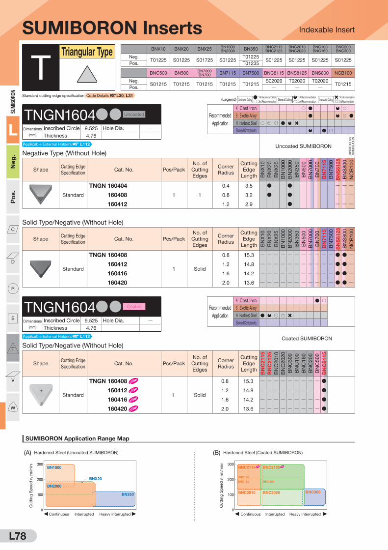
L78
SUMIBORON Application Range Map
Indexable Insert
300
200
100
0Heavy InterruptedContinuous Interrupted
BNX20
BN1000
BN350
BN2000
Cu
ttin
g S
peed
vc
( m/m
in) 300
200
100
0Heavy InterruptedContinuous Interrupted
BNC2010 BNC2020
BNC160
BNC100
BNC200
BNC2115 BNC2125
BNC300
Cu
ttin
g S
peed
vc
( m/m
in)
(A) Hardened Steel (Uncoated SUMIBORON) (B) Hardened Steel (Coated SUMIBORON)
SUMIBORO
N
L
Neg.
Pos.
C
D
R
S
T
V
W
Recommended
Application
K Cast Iron
S Exotic Alloy
H Hardened Steel
Sintered Components
BNX10 BNX20 BNX25BN1000BN2000 BN350
BNC2115BNC2125
BNC2010BNC2020
BNC100BNC160
BNC200BNC300
Neg.T01225 S01225 S01725 S01225
T01225S01225 S01225 S01225 S01225
Pos. T01235
BNC500 BN500BN7000BN700 BN7115 BN7500 BNC8115 BNS8125 BNS800 NCB100
Neg.S01215 T01215 T01215 T01215 T01215
S02020 T02020 T02020T01215
Pos. Q Q Q
(Legend) Continuous Cutting : 1st Recommendation
General Cutting : 1st Recommendation
Interrupted Cutting : 1st Recommendation
: 2nd Recommendation : 2nd Recommendation : 2nd Recommendation
Recommended
Application
K Cast Iron
S Exotic Alloy
H Hardened Steel
Sintered Components
SUMIBORON Inserts
Negative Type (Without Hole)
Uncoated SUMIBORON
BIN
DE
RLE
SS
S
UM
IBO
RO
N
ShapeCutting Edge
SpecificationCat. No. Pcs/Pack
No. of
Cutting
Edges
Corner
Radius
Cutting
Edge
Length BN
X1
0
BN
X2
0
BN
X2
5
BN
10
00
BN
20
00
BN
35
0
BN
50
0
BN
70
00
BN
70
0
BN
71
15
BN
75
00
BN
S8125
BN
S8
00
NC
B1
00
Standard
TNGN 160404
1 1
0.4 3.5 D D Q Q Q
TNGN 160408 0.8 3.2 D D Q Q Q
TNGN 160412 1.2 2.9 D Q Q Q
TTriangular Type
TNGN1604DD Uncoated
Dimensions
(mm)
Inscribed Circle 9.525 Hole Dia. QThickness 4.76
Applicable External Holders L112
Solid Type/Negative (Without Hole)
Coated SUMIBORON
ShapeCutting Edge
SpecificationCat. No. Pcs/Pack
No. of
Cutting
Edges
Corner
Radius
Cutting
Edge
Length
BN
C2
11
5
BN
C2
12
5
BN
C2
01
0
BN
C2
02
0
BN
C3
00
BN
C1
00
BN
C1
60
BN
C2
00
BN
C5
00
BN
C8
11
5
Standard
TNGN 160408
1 Solid
0.8 15.3 Q Q Q Q Q Q Q Q Q D
TNGN 160412 1.2 14.8 Q Q Q Q Q Q Q Q Q D
TNGN 160416 1.6 14.2 Q Q Q Q Q Q Q Q Q D
TNGN 160420 2.0 13.6 Q Q Q Q Q Q Q Q Q D
TNGN1604DD Coated
Dimensions
(mm)
Inscribed Circle 9.525 Hole Dia. QThickness 4.76
Applicable External Holders L112
Solid Type/Negative (Without Hole)
ShapeCutting Edge
SpecificationCat. No. Pcs/Pack
No. of
Cutting
Edges
Corner
Radius
Cutting
Edge
Length BN
X1
0
BN
X2
0
BN
X2
5
BN
10
00
BN
20
00
BN
35
0
BN
50
0
BN
70
00
BN
70
0
BN
71
15
BN
75
00
BN
S8125
BN
S8
00
NC
B1
00
Standard
TNGN 160408
1 Solid
0.8 15.3 Q Q Q Q Q Q Q Q Q Q Q D D Q
TNGN 160412 1.2 14.8 Q Q Q Q Q Q Q Q Q Q Q D D Q
TNGN 160416 1.6 14.2 Q Q Q Q Q Q Q Q Q Q Q D D Q
TNGN 160420 2.0 13.6 Q Q Q Q Q Q Q Q Q Q Q D D Q
Standard cutting edge specification Code Details L30, L31

L79
SUMIBORON Application Range Map
(D) Ductile Cast Iron (G) Titanium Alloy
Indexable Insert
0 1.0 2.0 3.0
300
500
200
400
Depth of Cut ap (mm)
BNC500
BNC8115
BNS8125BN7000
Cutt
ing
Sp
eed
vc
( m/m
in)
100
200
300
Depth of Cut ap(mm)
Feed Rate f(mm/rev)
0 0.1
0.150.10.05 0.2 0.25 0.3
0.2 0.3 0.4 0.5
Finishing region
Roughing region
BN7500BN7115 BN7000
Cutt
ing
Sp
eed
vc
( m/m
in)
Depth of Cut ap(mm)
Feed Rate f(mm/rev)
0 0.1
0.150.10.05 0.2 0.25 0.3
0.2 0.3 0.4 0.5
100
200
300
Finishing region
Roughing region
BN7500BN7115 BN7000
Cutt
ing
Sp
eed
vc
( m/m
in)
0
100
200
300
0.05 0.10 0.15 0.20
Feed Rate f (mm/rev)
NCB100
Cutt
ing
Sp
eed
vc
( m/m
in)Finishing
regionRoughing region
0 1.0 2.0 3.0 4.0
1,000
2,000
2,500
500
1,500
Depth of Cut ap (mm)
BNS800
BN7000
BN500
BNC8115BNS8125
Cutt
ing
Sp
eed
vc
( m/m
in)
SUMIBO
RON
L
Neg.
Pos.
C
D
R
S
T
V
W
(C) Gray Cast Iron (E) General Sintered Alloy (F) High-density Sintered Alloy
(Legend) Continuous Cutting : 1st Recommendation
General Cutting : 1st Recommendation
Interrupted Cutting : 1st Recommendation
: 2nd Recommendation : 2nd Recommendation : 2nd Recommendation
Recommended
Application
K Cast Iron
S Exotic Alloy
H Hardened Steel
Sintered Components
Recommended
Application
K Cast Iron
S Exotic Alloy
H Hardened Steel
Sintered Components
SUMIBORON Inserts
Single-Use Type/5° Positive (With Hole)
Uncoated SUMIBORON
BIN
DE
RLE
SS
S
UM
IBO
RO
N
ShapeCutting Edge
SpecificationCat. No. Pcs/Pack
No. of
Cutting
Edges
Corner
Radius
Cutting
Edge
Length BN
X1
0
BN
X2
0
BN
X2
5
BN
10
00
BN
20
00
BN
35
0
BN
50
0
BN
70
00
BN
70
0
BN
71
15
BN
75
00
BN
S8125
BN
S8
00
NC
B1
00
Low Cutting Force
Sharp
Edge
NU-TBEW 060102LF
1 1
0.2 2.1 Q Q Q Q Q Q Q Q Q
Sharper Edge Type
T00715
NU-TBEW 060102LT
1 1
0.2 2.1 Q D Q Q Q Q Q Q Q Q Q Q Q Q
*Depth of cut for single-use types is 0.5mm or less.
TTriangular Type
TBEW0601DD Uncoated
Dimensions
(mm)
Inscribed Circle 3.97 Hole Dia. 2.2
Thickness 1.59
5° Positive Type (Without Hole)
Uncoated SUMIBORON
BIN
DE
RLE
SS
S
UM
IBO
RO
N
ShapeCutting Edge
SpecificationCat. No. Pcs/Pack
No. of
Cutting
Edges
Corner
Radius
Cutting
Edge
Length BN
X1
0
BN
X2
0
BN
X2
5
BN
10
00
BN
20
00
BN
35
0
BN
50
0
BN
70
00
BN
70
0
BN
71
15
BN
75
00
BN
S8125
BN
S8
00
NC
B1
00
Standard
TBGN 060102B
1 3
0.2 6.5 D D Q Q Q
TBGN 060104B 0.4 6.3 D D D D D D Q Q Q
TBGN 060108B 0.8 5.7 D D D D D Q Q Q
Sharper Edge Type
Standard
TBGN 060102-BSTN
1 3
0.2 6.5 Q D Q Q Q Q Q Q Q Q Q Q Q Q
TBGN 060104-BSTN 0.4 6.3 Q D Q Q Q Q Q Q Q Q Q Q Q Q
TBGN 060108-BSTN 0.8 5.7 Q D Q Q Q Q Q Q Q Q Q Q Q Q
TBGN0601DD Uncoated
Dimensions
(mm)
Inscribed Circle 3.97 Hole Dia. QThickness 1.59
Applicable Internal Holders E56, E58
Applicable Internal Holders E76
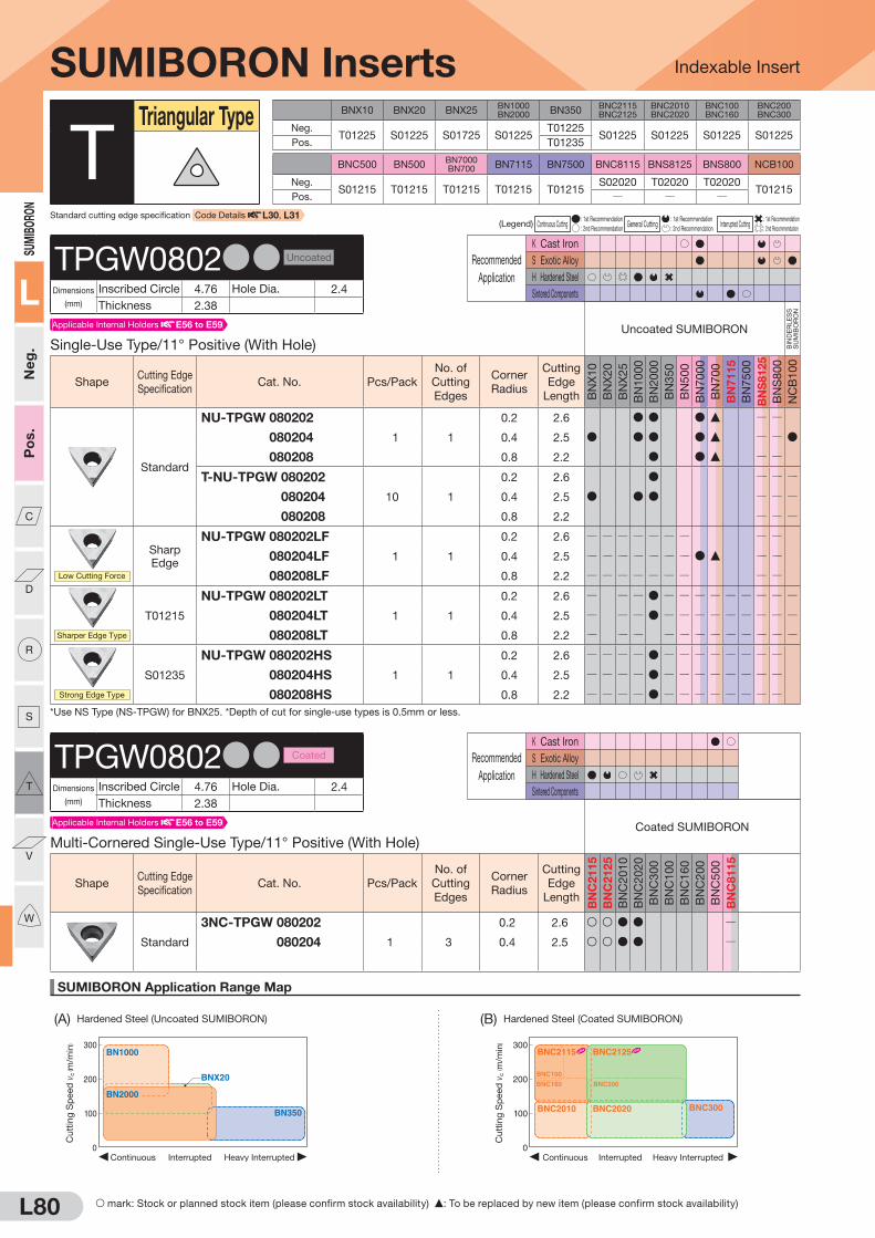
(A) Hardened Steel (Uncoated SUMIBORON) (B) Hardened Steel (Coated SUMIBORON)
SUMIBORO
N
L
Neg.
Pos.
C
D
R
S
T
V
W
L80
SUMIBORON Application Range Map
Indexable Insert
300
200
100
0Heavy InterruptedContinuous Interrupted
BNX20
BN1000
BN350
BN2000
Cu
ttin
g S
peed
vc
( m/m
in) 300
200
100
0Heavy InterruptedContinuous Interrupted
BNC2010 BNC2020
BNC160
BNC100
BNC200
BNC2115 BNC2125
BNC300
Cu
ttin
g S
peed
vc
( m/m
in)
Recommended
Application
K Cast Iron
S Exotic Alloy
H Hardened Steel
Sintered Components
S mark: Stock or planned stock item (please confirm stock availability) F: To be replaced by new item (please confirm stock availability)
BNX10 BNX20 BNX25BN1000BN2000 BN350
BNC2115BNC2125
BNC2010BNC2020
BNC100BNC160
BNC200BNC300
Neg.T01225 S01225 S01725 S01225
T01225S01225 S01225 S01225 S01225
Pos. T01235
BNC500 BN500BN7000BN700 BN7115 BN7500 BNC8115 BNS8125 BNS800 NCB100
Neg.S01215 T01215 T01215 T01215 T01215
S02020 T02020 T02020T01215
Pos. Q Q Q
(Legend) Continuous Cutting : 1st Recommendation
General Cutting : 1st Recommendation
Interrupted Cutting : 1st Recommendation
: 2nd Recommendation : 2nd Recommendation : 2nd Recommendation
Recommended
Application
K Cast Iron
S Exotic Alloy
H Hardened Steel
Sintered Components
SUMIBORON Inserts
Single-Use Type/11° Positive (With Hole)
Uncoated SUMIBORON
BIN
DE
RLE
SS
S
UM
IBO
RO
N
ShapeCutting Edge
SpecificationCat. No. Pcs/Pack
No. of
Cutting
Edges
Corner
Radius
Cutting
Edge
Length BN
X1
0
BN
X2
0
BN
X2
5
BN
10
00
BN
20
00
BN
35
0
BN
50
0
BN
70
00
BN
70
0
BN
71
15
BN
75
00
BN
S8125
BN
S8
00
NC
B1
00
Standard
NU-TPGW 080202
1 1
0.2 2.6 D D D F Q Q
NU-TPGW 080204 0.4 2.5 D D D D F Q Q D
NU-TPGW 080208 0.8 2.2 D D F Q Q
T-NU-TPGW 080202
10 1
0.2 2.6 D Q Q Q
T-NU-TPGW 080204 0.4 2.5 D D D Q Q Q
T-NU-TPGW 080208 0.8 2.2 Q Q Q
Low Cutting Force
Sharp
Edge
NU-TPGW 080202LF
1 1
0.2 2.6 Q Q Q Q Q Q Q Q Q
NU-TPGW 080204LF 0.4 2.5 Q Q Q Q Q Q Q D F Q Q
NU-TPGW 080208LF 0.8 2.2 Q Q Q Q Q Q Q Q Q
Sharper Edge Type
T01215
NU-TPGW 080202LT
1 1
0.2 2.6 Q Q Q D Q Q Q Q Q Q Q Q Q
NU-TPGW 080204LT 0.4 2.5 Q Q Q D Q Q Q Q Q Q Q Q Q
NU-TPGW 080208LT 0.8 2.2 Q Q Q Q Q Q Q Q Q Q Q Q
Strong Edge Type
S01235
NU-TPGW 080202HS
1 1
0.2 2.6 Q Q Q Q D Q Q Q Q Q Q Q Q
NU-TPGW 080204HS 0.4 2.5 Q Q Q Q D Q Q Q Q Q Q Q Q
NU-TPGW 080208HS 0.8 2.2 Q Q Q Q D Q Q Q Q Q Q Q Q
*Use NS Type (NS-TPGW) for BNX25. *Depth of cut for single-use types is 0.5mm or less.
TTriangular Type
TPGW0802DD Uncoated
Dimensions
(mm)
Inscribed Circle 4.76 Hole Dia. 2.4
Thickness 2.38
Multi-Cornered Single-Use Type/11° Positive (With Hole)
Coated SUMIBORON
ShapeCutting Edge
SpecificationCat. No. Pcs/Pack
No. of
Cutting
Edges
Corner
Radius
Cutting
Edge
Length
BN
C2
11
5
BN
C2
12
5
BN
C2
01
0
BN
C2
02
0
BN
C3
00
BN
C1
00
BN
C1
60
BN
C2
00
BN
C5
00
BN
C8
11
5
Standard
3NC-TPGW 080202
1 3
0.2 2.6 S S D D Q
3NC-TPGW 080204 0.4 2.5 S S D D Q
TPGW0802DD Coated
Dimensions
(mm)
Inscribed Circle 4.76 Hole Dia. 2.4
Thickness 2.38
Standard cutting edge specification Code Details L30, L31
Applicable Internal Holders E56 to E59
Applicable Internal Holders E56 to E59
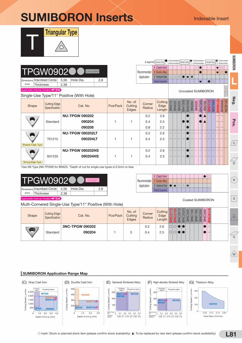
SUMIBO
RON
L
Neg.
Pos.
C
D
R
S
T
V
W
(C) Gray Cast Iron (E) General Sintered Alloy (F) High-density Sintered Alloy
L81
SUMIBORON Application Range Map
(D) Ductile Cast Iron
Indexable Insert
0 1.0 2.0 3.0
300
500
200
400
Depth of Cut ap (mm)
BNC500
BNC8115
BNS8125BN7000
Cutt
ing
Sp
eed
vc
( m/m
in)
100
200
300
Depth of Cut ap(mm)
Feed Rate f(mm/rev)
0 0.1
0.150.10.05 0.2 0.25 0.3
0.2 0.3 0.4 0.5
Finishing region
Roughing region
BN7500BN7115 BN7000
Cutt
ing
Sp
eed
vc
( m/m
in)
Depth of Cut ap(mm)
Feed Rate f(mm/rev)
0 0.1
0.150.10.05 0.2 0.25 0.3
0.2 0.3 0.4 0.5
100
200
300
Finishing region
Roughing region
BN7500BN7115 BN7000
Cutt
ing
Sp
eed
vc
( m/m
in)
0
100
200
300
0.05 0.10 0.15 0.20
Feed Rate f (mm/rev)
NCB100
Cutt
ing
Sp
eed
vc
( m/m
in)Finishing
regionRoughing region
0 1.0 2.0 3.0 4.0
1,000
2,000
2,500
500
1,500
Depth of Cut ap (mm)
BNS800
BN7000
BN500
BNC8115BNS8125
Cutt
ing
Sp
eed
vc
( m/m
in)
Recommended
Application
K Cast Iron
S Exotic Alloy
H Hardened Steel
Sintered Components
S mark: Stock or planned stock item (please confirm stock availability) F: To be replaced by new item (please confirm stock availability)
(G) Titanium Alloy
(Legend) Continuous Cutting : 1st Recommendation
General Cutting : 1st Recommendation
Interrupted Cutting : 1st Recommendation
: 2nd Recommendation : 2nd Recommendation : 2nd Recommendation
Recommended
Application
K Cast Iron
S Exotic Alloy
H Hardened Steel
Sintered Components
SUMIBORON Inserts
Single-Use Type/11° Positive (With Hole)
Uncoated SUMIBORON
BIN
DE
RLE
SS
S
UM
IBO
RO
N
ShapeCutting Edge
SpecificationCat. No. Pcs/Pack
No. of
Cutting
Edges
Corner
Radius
Cutting
Edge
Length BN
X1
0
BN
X2
0
BN
X2
5
BN
10
00
BN
20
00
BN
35
0
BN
50
0
BN
70
00
BN
70
0
BN
71
15
BN
75
00
BN
S8125
BN
S8
00
NC
B1
00
Standard
NU-TPGW 090202
1 1
0.2 2.6 D D F Q Q
NU-TPGW 090204 0.4 2.5 D D D F Q Q
NU-TPGW 090208 0.8 2.2 D Q Q
Sharper Edge Type
T01215
NU-TPGW 090202LT
1 1
0.2 2.6 Q Q Q Q D Q Q Q Q Q Q Q Q Q
NU-TPGW 090204LT 0.4 2.5 Q Q Q Q D Q Q Q Q Q Q Q Q Q
Strong Edge Type
S01235
NU-TPGW 090202HS
1 1
0.2 2.6 Q Q Q Q D Q Q Q Q Q Q Q Q
NU-TPGW 090204HS 0.4 2.5 Q Q Q Q D Q Q Q Q Q Q Q Q
*Use NS Type (NS-TPGW) for BNX25. *Depth of cut for single-use types is 0.5mm or less.
TTriangular Type
TPGW0902DD Uncoated
Dimensions
(mm)
Inscribed Circle 5.56 Hole Dia. 2.8
Thickness 2.38
Multi-Cornered Single-Use Type/11° Positive (With Hole)
Coated SUMIBORON
ShapeCutting Edge
SpecificationCat. No. Pcs/Pack
No. of
Cutting
Edges
Corner
Radius
Cutting
Edge
Length
BN
C2
11
5
BN
C2
12
5
BN
C2
01
0
BN
C2
02
0
BN
C3
00
BN
C1
00
BN
C1
60
BN
C2
00
BN
C5
00
BN
C8
11
5
Standard
3NC-TPGW 090202
1 3
0.2 2.6 S S D D D Q
3NC-TPGW 090204 0.4 2.5 S S D D D Q
TPGW0902DD Coated
Dimensions
(mm)
Inscribed Circle 5.56 Hole Dia. 2.8
Thickness 2.38
Applicable Internal Holders E56
Applicable Internal Holders E56

L82
SUMIBORON Application Range Map
Indexable Insert
300
200
100
0Heavy InterruptedContinuous Interrupted
BNX20
BN1000
BN350
BN2000
Cu
ttin
g S
peed
vc
( m/m
in) 300
200
100
0Heavy InterruptedContinuous Interrupted
BNC2010 BNC2020
BNC160
BNC100
BNC200
BNC2115 BNC2125
BNC300
Cu
ttin
g S
peed
vc
( m/m
in)
(A) Hardened Steel (Uncoated SUMIBORON) (B) Hardened Steel (Coated SUMIBORON)
SUMIBORO
N
L
Neg.
Pos.
C
D
R
S
T
V
W
F mark: To be replaced by a new product, made to order, or discontinued (please confirm stock availability).
BNX10 BNX20 BNX25BN1000BN2000 BN350
BNC2115BNC2125
BNC2010BNC2020
BNC100BNC160
BNC200BNC300
Neg.T01225 S01225 S01725 S01225
T01225S01225 S01225 S01225 S01225
Pos. T01235
BNC500 BN500BN7000BN700 BN7115 BN7500 BNC8115 BNS8125 BNS800 NCB100
Neg.S01215 T01215 T01215 T01215 T01215
S02020 T02020 T02020T01215
Pos. Q Q Q
(Legend) Continuous Cutting : 1st Recommendation
General Cutting : 1st Recommendation
Interrupted Cutting : 1st Recommendation
: 2nd Recommendation : 2nd Recommendation : 2nd Recommendation
Recommended
Application
K Cast Iron
S Exotic Alloy
H Hardened Steel
Sintered Components
Multi-Cornered Single-Use Type/11° Positive (With Hole)
ShapeCutting Edge
SpecificationCat. No. Pcs/Pack
No. of
Cutting
Edges
Corner
Radius
Cutting
Edge
Length BN
X1
0
BN
X2
0
BN
X2
5
BN
10
00
BN
20
00
BN
35
0
BN
50
0
BN
70
00
BN
70
0
BN
71
15
BN
75
00
BN
S8125
BN
S8
00
NC
B1
00
Standard
3NU-TPGW 110204
1 3
0.4 2.3 D D Q Q
3NU-TPGW 110208 0.8 2.0 D D Q Q
Low Cutting Force
Sharp
Edge
3NU-TPGW 110204LF
1 3
0.4 2.3 Q Q Q Q Q Q Q D D Q Q
Low Cutting Force
Honing
3NU-TPGW 110204LE
1 3
0.4 2.3 Q Q Q Q Q Q Q Q D Q Q
General-purpose Type for Continuous Cutting
S00715
3NU-TPGW 110204LS
1 3
0.4 2.3 Q Q Q Q Q Q Q Q D Q Q
*Use 3NS Type (3NS-TPGW) for BNX25. *Depth of cut for single-use types is 0.5mm or less.
SUMIBORON Inserts
Single-Use Type/11° Positive (With Hole)Uncoated SUMIBORON
BIN
DE
RLE
SS
S
UM
IBO
RO
N
ShapeCutting Edge
SpecificationCat. No. Pcs/Pack
No. of
Cutting
Edges
Corner
Radius
Cutting
Edge
Length BN
X1
0
BN
X2
0
BN
X2
5
BN
10
00
BN
20
00
BN
35
0
BN
50
0
BN
70
00
BN
70
0
BN
71
15
BN
75
00
BN
S8125
BN
S8
00
NC
B1
00
Standard
NU-TPGW 110202
1 1
0.2 2.5 D D F Q Q
NU-TPGW 110204 0.4 2.3 D D D F Q Q
NU-TPGW 110208 0.8 2.0 Q Q
T-NU-TPGW 110202
10 1
0.2 2.5 Q Q Q
T-NU-TPGW 110204 0.4 2.3 D D Q Q Q
T-NU-TPGW 110208 0.8 2.0 Q Q Q
Sharper Edge Type
T01215
NU-TPGW 110202LT
1 1
0.2 2.5 Q Q Q D Q Q Q Q Q Q Q Q Q
NU-TPGW 110204LT 0.4 2.3 Q Q Q D Q Q Q Q Q Q Q Q Q
NU-TPGW 110208LT 0.8 2.0 Q Q Q Q Q Q Q Q Q Q Q Q
Strong Edge Type
S01235
NU-TPGW 110204HS
1 1
0.4 2.3 Q Q Q Q D Q Q Q Q Q Q Q Q
*Use NS Type (NS-TPGW) for BNX25. *Depth of cut for single-use types is 0.5mm or less.
TTriangular Type
TPGW1102DD Uncoated
Dimensions
(mm)
Inscribed Circle 6.35 Hole Dia. 2.8
Thickness 2.38
Standard cutting edge specification Code Details L30, L31
Applicable Internal Holders E56

L83
SUMIBORON Application Range Map
(D) Ductile Cast Iron (G) Titanium Alloy
Indexable Insert
0 1.0 2.0 3.0
300
500
200
400
Depth of Cut ap (mm)
BNC500
BNC8115
BNS8125BN7000
Cutt
ing
Sp
eed
vc
( m/m
in)
100
200
300
Depth of Cut ap(mm)
Feed Rate f(mm/rev)
0 0.1
0.150.10.05 0.2 0.25 0.3
0.2 0.3 0.4 0.5
Finishing region
Roughing region
BN7500BN7115 BN7000
Cutt
ing
Sp
eed
vc
( m/m
in)
Depth of Cut ap(mm)
Feed Rate f(mm/rev)
0 0.1
0.150.10.05 0.2 0.25 0.3
0.2 0.3 0.4 0.5
100
200
300
Finishing region
Roughing region
BN7500BN7115 BN7000
Cutt
ing
Sp
eed
vc
( m/m
in)
0
100
200
300
0.05 0.10 0.15 0.20
Feed Rate f (mm/rev)
NCB100
Cutt
ing
Sp
eed
vc
( m/m
in)Finishing
regionRoughing region
0 1.0 2.0 3.0 4.0
1,000
2,000
2,500
500
1,500
Depth of Cut ap (mm)
BNS800
BN7000
BN500
BNC8115BNS8125
Cutt
ing
Sp
eed
vc
( m/m
in)
SUMIBO
RON
L
Neg.
Pos.
C
D
R
S
T
V
W
(C) Gray Cast Iron (E) General Sintered Alloy (F) High-density Sintered Alloy
F mark: To be replaced by a new product, made to order, or discontinued (please confirm stock availability).
(Legend) Continuous Cutting : 1st Recommendation
General Cutting : 1st Recommendation
Interrupted Cutting : 1st Recommendation
: 2nd Recommendation : 2nd Recommendation : 2nd Recommendation
Recommended
Application
K Cast Iron
S Exotic Alloy
H Hardened Steel
Sintered Components
SUMIBORON Inserts
Single-Use Type/11° Positive (With Hole)Uncoated SUMIBORON
BIN
DE
RLE
SS
S
UM
IBO
RO
N
ShapeCutting Edge
SpecificationCat. No. Pcs/Pack
No. of
Cutting
Edges
Corner
Radius
Cutting
Edge
Length BN
X1
0
BN
X2
0
BN
X2
5
BN
10
00
BN
20
00
BN
35
0
BN
50
0
BN
70
00
BN
70
0
BN
71
15
BN
75
00
BN
S8125
BN
S8
00
NC
B1
00
Standard
NU-TPGW 110302
1 1
0.2 2.6 D D Q D D D D F Q Q
NU-TPGW 110304 0.4 2.5 D D Q D D D D D F Q Q
NU-TPGW 110308 0.8 2.2 D D Q D D D D D F Q Q
T-NU-TPGW 110302
10 1
0.2 2.6 D D Q D D Q Q Q
T-NU-TPGW 110304 0.4 2.5 D D Q D D D Q Q Q
T-NU-TPGW 110308 0.8 2.2 D D Q D D D Q Q Q
Standard
NS-TPGW 110302
1 1
0.2 2.6 Q Q Q Q Q Q Q Q Q Q Q Q Q
NS-TPGW 110304 0.4 2.5 Q Q F Q Q Q Q Q Q Q Q Q Q Q
NS-TPGW 110308 0.8 2.2 Q Q F Q Q Q Q Q Q Q Q Q Q Q
T-NS-TPGW 110302
10 1
0.2 2.6 Q Q Q Q Q Q Q Q Q Q Q Q Q
T-NS-TPGW 110304 0.4 2.5 Q Q F Q Q Q Q Q Q Q Q Q Q Q
T-NS-TPGW 110308 0.8 2.2 Q Q F Q Q Q Q Q Q Q Q Q Q Q
Low Cutting Force
Sharp
Edge
NU-TPGW 110302LF
1 1
0.2 2.6 Q Q Q Q Q Q Q D F Q Q
NU-TPGW 110304LF 0.4 2.5 Q Q Q Q Q Q Q D F Q Q
NU-TPGW 110308LF 0.8 2.2 Q Q Q Q Q Q Q D F Q Q
Sharper Edge Type
T01215
NU-TPGW 110302LT
1 1
0.2 2.6 Q D Q Q D Q Q Q Q Q Q Q Q Q
NU-TPGW 110304LT 0.4 2.5 Q D Q Q D Q Q Q Q Q Q Q Q Q
NU-TPGW 110308LT 0.8 2.2 Q D Q Q D Q Q Q Q Q Q Q Q Q
Strong Edge Type
S01235
NU-TPGW 110302HS
1 1
0.2 2.6 Q Q Q Q D Q Q Q Q Q Q Q Q
NU-TPGW 110304HS 0.4 2.5 Q Q Q Q D Q Q Q Q Q Q Q Q
NU-TPGW 110308HS 0.8 2.2 Q Q Q Q D Q Q Q Q Q Q Q Q
*Depth of cut for single-use types is 0.5mm or less.
TTriangular Type
TPG 1103DD Uncoated
Dimensions
(mm)
Inscribed Circle 6.35 Hole Dia. 3.4
Thickness 3.18
Applicable Internal Holders E14, E56 to E59
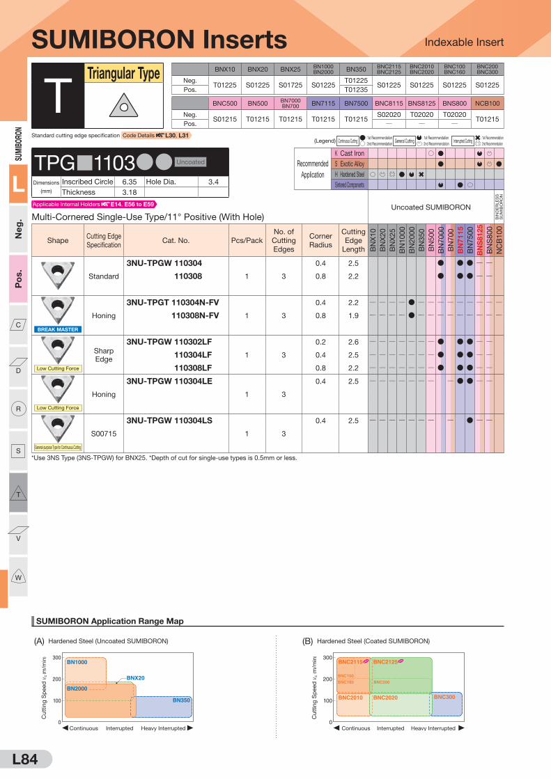
(A) Hardened Steel (Uncoated SUMIBORON) (B) Hardened Steel (Coated SUMIBORON)
SUMIBORO
N
L
Neg.
Pos.
C
D
R
S
T
V
W
L84
SUMIBORON Application Range Map
Indexable Insert
300
200
100
0Heavy InterruptedContinuous Interrupted
BNX20
BN1000
BN350
BN2000
Cut
ting
Sp
eed
vc
( m/m
in) 300
200
100
0Heavy InterruptedContinuous Interrupted
BNC2010 BNC2020
BNC160
BNC100
BNC200
BNC2115 BNC2125
BNC300
Cut
ting
Sp
eed
vc
( m/m
in)
BNX10 BNX20 BNX25BN1000BN2000 BN350
BNC2115BNC2125
BNC2010BNC2020
BNC100BNC160
BNC200BNC300
Neg.T01225 S01225 S01725 S01225
T01225S01225 S01225 S01225 S01225
Pos. T01235
BNC500 BN500BN7000BN700 BN7115 BN7500 BNC8115 BNS8125 BNS800 NCB100
Neg.S01215 T01215 T01215 T01215 T01215
S02020 T02020 T02020T01215
Pos. Q Q Q
(Legend) Continuous Cutting : 1st Recommendation
General Cutting : 1st Recommendation
Interrupted Cutting : 1st Recommendation
: 2nd Recommendation : 2nd Recommendation : 2nd Recommendation
Recommended
Application
K Cast Iron
S Exotic Alloy
H Hardened Steel
Sintered Components
SUMIBORON Inserts
Multi-Cornered Single-Use Type/11° Positive (With Hole)Uncoated SUMIBORON
BIN
DE
RLE
SS
S
UM
IBO
RO
N
ShapeCutting Edge
SpecificationCat. No. Pcs/Pack
No. of
Cutting
Edges
Corner
Radius
Cutting
Edge
Length BN
X1
0
BN
X2
0
BN
X2
5
BN
10
00
BN
20
00
BN
35
0
BN
50
0
BN
70
00
BN
70
0
BN
71
15
BN
75
00
BN
S8125
BN
S8
00
NC
B1
00
Standard
3NU-TPGW 110304
1 3
0.4 2.5 D D D Q Q
3NU-TPGW 110308 0.8 2.2 D D D Q Q
BREAK MASTER
Honing
3NU-TPGT 110304N-FV
1 3
0.4 2.2 Q Q Q Q D Q Q Q Q Q Q Q Q Q
3NU-TPGT 110308N-FV 0.8 1.9 Q Q Q Q D Q Q Q Q Q Q Q Q Q
Low Cutting Force
Sharp
Edge
3NU-TPGW 110302LF
1 3
0.2 2.6 Q Q Q Q Q Q Q D D D Q Q
3NU-TPGW 110304LF 0.4 2.5 Q Q Q Q Q Q Q D D D Q Q
3NU-TPGW 110308LF 0.8 2.2 Q Q Q Q Q Q Q D D D Q Q
Low Cutting Force
Honing
3NU-TPGW 110304LE
1 3
0.4 2.5 Q Q Q Q Q Q Q Q D D Q Q
General-purpose Type for Continuous Cutting
S00715
3NU-TPGW 110304LS
1 3
0.4 2.5 Q Q Q Q Q Q Q Q D Q Q
*Use 3NS Type (3NS-TPGW) for BNX25. *Depth of cut for single-use types is 0.5mm or less.
TTriangular Type
TPG 1103DD Uncoated
Dimensions
(mm)
Inscribed Circle 6.35 Hole Dia. 3.4
Thickness 3.18
Standard cutting edge specification Code Details L30, L31
Applicable Internal Holders E14, E56 to E59

SUMIBO
RON
L
Neg.
Pos.
C
D
R
S
T
V
W
(F) High-density Sintered Alloy(E) General Sintered Alloy(C) Gray Cast Iron
L85
SUMIBORON Application Range Map
(D) Ductile Cast Iron (G) Titanium Alloy
Indexable Insert
0 1.0 2.0 3.0
300
500
200
400
Depth of Cut ap (mm)
BNC500
BNC8115
BNS8125BN7000
Cut
ting
Sp
eed
vc
( m/m
in)
100
200
300
Depth of Cut ap(mm)
Feed Rate f(mm/rev)
0 0.1
0.150.10.05 0.2 0.25 0.3
0.2 0.3 0.4 0.5
Finishing region Roughing region
BN7500BN7115 BN7000
Cut
ting
Sp
eed
vc
( m/m
in)
Depth of Cut ap(mm)
Feed Rate f(mm/rev)
0 0.1
0.150.10.05 0.2 0.25 0.3
0.2 0.3 0.4 0.5
100
200
300
Finishing region Roughing region
BN7500BN7115 BN7000
Cut
ting
Sp
eed
vc
( m/m
in)
0
100
200
300
0.05 0.10 0.15 0.20
Feed Rate f (mm/rev)
NCB100
Cut
ting
Sp
eed
vc
( m/m
in)Finishing
region Roughing region
0 1.0 2.0 3.0 4.0
1,000
2,000
2,500
500
1,500
Depth of Cut ap (mm)
BNS800
BN7000
BN500
BNC8115BNS8125
Cut
ting
Sp
eed
vc
( m/m
in)
(Legend) Continuous Cutting : 1st Recommendation
General Cutting : 1st Recommendation
Interrupted Cutting : 1st Recommendation
: 2nd Recommendation : 2nd Recommendation : 2nd Recommendation
Recommended
Application
K Cast Iron
S Exotic Alloy
H Hardened Steel
Sintered Components
SUMIBORON Inserts
11° Positive Type (With Hole)Uncoated SUMIBORON
BIN
DE
RLE
SS
S
UM
IBO
RO
N
ShapeCutting Edge
SpecificationCat. No. Pcs/Pack
No. of
Cutting
Edges
Corner
Radius
Cutting
Edge
Length BN
X1
0
BN
X2
0
BN
X2
5
BN
10
00
BN
20
00
BN
35
0
BN
50
0
BN
70
00
BN
70
0
BN
71
15
BN
75
00
BN
S8125
BN
S8
00
NC
B1
00
Standard
TPGW 110304
1 1
0.4 3.5 D D D F Q Q Q
TPGW 110308 0.8 3.2 D D Q Q Q
Strong Edge Type
S01235
TPGW 110304HS
1 1
0.4 3.5 Q Q Q Q D Q Q Q Q Q Q Q Q Q
TPGW 110308HS 0.8 3.2 Q Q Q Q D Q Q Q Q Q Q Q Q Q
TTriangular Type
TPG 1103DD Uncoated
Dimensions
(mm)
Inscribed Circle 6.35 Hole Dia. 3.4
Thickness 3.18
Applicable Internal Holders E14, E56 to E59
F mark: To be replaced by a new product, made to order, or discontinued (please confirm stock availability).

(A) Hardened Steel (Uncoated SUMIBORON) (B) Hardened Steel (Coated SUMIBORON)
SUMIBORO
N
L
Neg.
Pos.
C
D
R
S
T
V
W
L86
SUMIBORON Application Range Map
Indexable Insert
300
200
100
0Heavy InterruptedContinuous Interrupted
BNX20
BN1000
BN350
BN2000
Cut
ting
Sp
eed
vc
( m/m
in) 300
200
100
0Heavy InterruptedContinuous Interrupted
BNC2010 BNC2020
BNC160
BNC100
BNC200
BNC2115 BNC2125
BNC300
Cut
ting
Sp
eed
vc
( m/m
in)
BNX10 BNX20 BNX25BN1000BN2000 BN350
BNC2115BNC2125
BNC2010BNC2020
BNC100BNC160
BNC200BNC300
Neg.T01225 S01225 S01725 S01225
T01225S01225 S01225 S01225 S01225
Pos. T01235
BNC500 BN500BN7000BN700 BN7115 BN7500 BNC8115 BNS8125 BNS800 NCB100
Neg.S01215 T01215 T01215 T01215 T01215
S02020 T02020 T02020T01215
Pos. Q Q Q
(Legend) Continuous Cutting : 1st Recommendation
General Cutting : 1st Recommendation
Interrupted Cutting : 1st Recommendation
: 2nd Recommendation : 2nd Recommendation : 2nd Recommendation
Recommended
Application
K Cast Iron
S Exotic Alloy
H Hardened Steel
Sintered Components
S mark: Stock or planned stock (please confirm stock availability)
SUMIBORON Inserts
Multi-Cornered Single-Use Type/11° Positive (With Hole)Coated SUMIBORON
ShapeCutting Edge
SpecificationCat. No. Pcs/Pack
No. of
Cutting
Edges
Corner
Radius
Cutting
Edge
Length
BN
C2
11
5
BN
C2
12
5
BN
C2
01
0
BN
C2
02
0
BN
C3
00
BN
C1
00
BN
C1
60
BN
C2
00
BN
C5
00
BN
C8
11
5
Standard
3NC-TPGW 110302
1 3
0.2 2.4 S S D D Q
3NC-TPGW 110304 0.4 2.3 S S D D D D D D D Q
3NC-TPGW 110308 0.8 2.0 S S D D D D D D D Q
BREAK MASTER
Honing
3NC-TPGT 110304N-FV
1 3
0.4 2.2 S S D D Q Q D D Q Q
3NC-TPGT 110308N-FV 0.8 1.9 S S D D Q Q D D Q Q
Low Cutting Force
Honing
3NC-TPGW 110302LE
1 3
0.2 2.4 Q Q D Q Q Q Q Q Q Q
3NC-TPGW 110304LE 0.4 2.3 Q Q D Q Q Q Q Q Q Q
3NC-TPGW 110308LE 0.8 2.0 Q Q D Q Q Q Q Q Q Q
Sharper Edge Type
T00515
3NC-TPGW 110302LT
1 3
0.2 2.4 Q Q Q D Q Q Q Q Q Q
3NC-TPGW 110304LT 0.4 2.3 Q Q Q D Q Q Q Q Q Q
3NC-TPGW 110308LT 0.8 2.0 Q Q Q D Q Q Q Q Q Q
Sharper Edge Type
BNC2115 S00515
BNC2125 S00515
BNC100 S01715
BNC160 S01020
BNC200 S01015
BNC300 S00515
3NC-TPGW 110302LS
1 3
0.2 2.6 S S Q
3NC-TPGW 110304LS 0.4 2.3 S S D D D D Q
3NC-TPGW 110308LS 0.8 2.0 S S D D D D Q
Strong Edge Type
BNC2115 S01730BNC2125 S02735BNC2010 S01730BNC2020 S02735BNC160 S01730BNC200 S01735BNC300 S01735BNC500 S01225
3NC-TPGW 110304HS
1 3
0.4 2.3 D Q
3NC-TPGW 110308HS 0.8 2.0 D Q
TTriangular Type
TPG 1103DD Coated
Dimensions
(mm)
Inscribed Circle 6.35 Hole Dia. 3.4
Thickness 3.18
Applicable Internal Holders E14, E56 to E59
Standard cutting edge specification Code Details L30, L31

SUM
IBORO
N
L
Ne
g.
Po
s.
C
D
R
S
T
V
W
(F) High-density Sintered Alloy(E) General Sintered Alloy(C) Gray Cast Iron
L87
SUMIBORON Application Range Map
(D) Ductile Cast Iron (G) Titanium Alloy
Indexable Insert
0 1.0 2.0 3.0
300
500
200
400
Depth of Cut ap (mm)
BNC500
BNC8115
BNS8125BN7000
Cutt
ing
Sp
eed
vc
( m/m
in)
100
200
300
Depth of Cut ap(mm)
Feed Rate f(mm/rev)
0 0.1
0.150.10.05 0.2 0.25 0.3
0.2 0.3 0.4 0.5
Finishing region
Roughing region
BN7500BN7115 BN7000
Cutt
ing
Sp
eed
vc
( m/m
in)
Depth of Cut ap(mm)
Feed Rate f(mm/rev)
0 0.1
0.150.10.05 0.2 0.25 0.3
0.2 0.3 0.4 0.5
100
200
300
Finishing region
Roughing region
BN7500BN7115 BN7000
Cutt
ing
Sp
eed
vc
( m/m
in)
0
100
200
300
0.05 0.10 0.15 0.20
Feed Rate f (mm/rev)
NCB100
Cutt
ing
Sp
eed
vc
( m/m
in)Finishing
regionRoughing region
0 1.0 2.0 3.0 4.0
1,000
2,000
2,500
500
1,500
Depth of Cut ap (mm)
BNS800
BN7000
BN500
BNC8115BNS8125
Cutt
ing
Sp
eed
vc
( m/m
in)
(Legend) Continuous Cutting : 1st Recommendation
General Cutting : 1st Recommendation
Interrupted Cutting : 1st Recommendation
: 2nd Recommendation : 2nd Recommendation : 2nd Recommendation
Recommended
Application
K Cast Iron
S Exotic Alloy
H Hardened Steel
Sintered Components
Recommended
Application
K Cast Iron
S Exotic Alloy
H Hardened Steel
Sintered Components
F mark: To be replaced by a new product, made to order, or discontinued (please confirm stock availability).
SUMIBORON Inserts
Single-Use Type/11° Positive (With Hole)Uncoated SUMIBORON
BIN
DE
RLE
SS
S
UM
IBO
RO
N
ShapeCutting Edge
SpecificationCat. No. Pcs/Pack
No. of
Cutting
Edges
Corner
Radius
Cutting
Edge
Length BN
X1
0
BN
X2
0
BN
X2
5
BN
10
00
BN
20
00
BN
35
0
BN
50
0
BN
70
00
BN
70
0
BN
71
15
BN
75
00
BN
S8125
BN
S8
00
NC
B1
00
Standard
NU-TPGW 160302
1 1
0.2 2.4 Q D Q Q
NU-TPGW 160304 0.4 2.3 Q D Q Q
NU-TPGW 160308 0.8 2.0 Q D Q Q
*Depth of cut for single-use types is 0.5mm or less.
TTriangular Type
TPGW1603DD Uncoated
Dimensions
(mm)
Inscribed Circle 9.525 Hole Dia. 4.4
Thickness 3.18
Single-Use Type/11° Positive (With Hole)Uncoated SUMIBORON
BIN
DE
RLE
SS
S
UM
IBO
RO
N
ShapeCutting Edge
SpecificationCat. No. Pcs/Pack
No. of
Cutting
Edges
Corner
Radius
Cutting
Edge
Length BN
X1
0
BN
X2
0
BN
X2
5
BN
10
00
BN
20
00
BN
35
0
BN
50
0
BN
70
00
BN
70
0
BN
71
15
BN
75
00
BN
S8125
BN
S8
00
NC
B1
00
Standard
NU-TPGW 160402
1 1
0.2 2.6 Q Q Q
NU-TPGW 160404 0.4 2.5 D D Q D D D D D F Q Q
NU-TPGW 160408 0.8 2.2 D D Q D D D D D F Q Q
T-NU-TPGW 160402
10 1
0.2 2.6 Q Q Q Q
T-NU-TPGW 160404 0.4 2.5 D D Q D D D D Q Q Q
T-NU-TPGW 160408 0.8 2.2 D D Q D D D Q Q Q
Standard
NS-TPGW 160402
1 1
0.2 2.6 Q Q Q Q Q Q Q Q Q Q Q Q Q
NS-TPGW 160404 0.4 2.5 Q Q F Q Q Q Q Q Q Q Q Q Q Q
NS-TPGW 160408 0.8 2.2 Q Q F Q Q Q Q Q Q Q Q Q Q Q
T-NS-TPGW 160402
10 1
0.2 2.6 Q Q Q Q Q Q Q Q Q Q Q Q Q
T-NS-TPGW 160404 0.4 2.5 Q Q F Q Q Q Q Q Q Q Q Q Q Q
T-NS-TPGW 160408 0.8 2.2 Q Q F Q Q Q Q Q Q Q Q Q Q Q*Depth of cut for single-use types is 0.5mm or less.
TPGW1604DD Uncoated
Dimensions
(mm)
Inscribed Circle 9.525 Hole Dia. 4.4
Thickness 4.76
Applicable Internal Holders E56
Applicable Internal Holders E14, E56 to E58

L88
SUMIBORON Application Range Map
Indexable Insert
300
200
100
0Heavy InterruptedContinuous Interrupted
BNX20
BN1000
BN350
BN2000
Cut
ting
Sp
eed
vc
( m/m
in) 300
200
100
0Heavy InterruptedContinuous Interrupted
BNC2010 BNC2020
BNC160
BNC100
BNC200
BNC2115 BNC2125
BNC300
Cut
ting
Sp
eed
vc
( m/m
in)
(A) Hardened Steel (Uncoated SUMIBORON) (B) Hardened Steel (Coated SUMIBORON)
SUM
IBO
RON
L
Ne
g.
Po
s.
C
D
R
S
T
V
W
BNX10 BNX20 BNX25BN1000BN2000 BN350
BNC2115BNC2125
BNC2010BNC2020
BNC100BNC160
BNC200BNC300
Neg.T01225 S01225 S01725 S01225
T01225S01225 S01225 S01225 S01225
Pos. T01235
BNC500 BN500BN7000BN700 BN7115 BN7500 BNC8115 BNS8125 BNS800 NCB100
Neg.S01215 T01215 T01215 T01215 T01215
S02020 T02020 T02020T01215
Pos. Q Q Q
(Legend) Continuous Cutting : 1st Recommendation
General Cutting : 1st Recommendation
Interrupted Cutting : 1st Recommendation
: 2nd Recommendation : 2nd Recommendation : 2nd Recommendation
Recommended
Application
K Cast Iron
S Exotic Alloy
H Hardened Steel
Sintered Components
11° Positive Type (With Hole)
ShapeCutting Edge
SpecificationCat. No. Pcs/Pack
No. of
Cutting
Edges
Corner
Radius
Cutting
Edge
Length BN
X1
0
BN
X2
0
BN
X2
5
BN
10
00
BN
20
00
BN
35
0
BN
50
0
BN
70
00
BN
70
0
BN
71
15
BN
75
00
BN
S8125
BN
S8
00
NC
B1
00
Standard
TPGW 160404
1 1
0.4 3.5 D D Q Q Q
TPGW 160408 0.8 3.2 D D Q Q Q
TPGW 160412 1.2 2.9 Q Q Q
Strong Edge Type
S01235
TPGW 160404HS
1 1
0.4 3.5 Q Q Q Q D Q Q Q Q Q Q Q Q Q
TPGW 160408HS 0.8 3.5 Q Q Q Q D Q Q Q Q Q Q Q Q Q
SUMIBORON Inserts
Single-Use Type/11° Positive (With Hole)Uncoated SUMIBORON
BIN
DE
RLE
SS
S
UM
IBO
RO
N
ShapeCutting Edge
SpecificationCat. No. Pcs/Pack
No. of
Cutting
Edges
Corner
Radius
Cutting
Edge
Length BN
X1
0
BN
X2
0
BN
X2
5
BN
10
00
BN
20
00
BN
35
0
BN
50
0
BN
70
00
BN
70
0
BN
71
15
BN
75
00
BN
S8125
BN
S8
00
NC
B1
00
Low Cutting Force
Sharp
Edge
NU-TPGW 160402LF
1 1
0.2 2.6 Q Q Q Q Q Q Q Q Q
NU-TPGW 160404LF 0.4 2.5 Q Q Q Q Q Q Q D F Q Q
NU-TPGW 160408LF 0.8 2.2 Q Q Q Q Q Q Q Q Q
Sharper Edge Type
T01215
NU-TPGW 160402LT
1 1
0.2 2.6 Q Q Q Q Q Q Q Q Q Q Q Q
NU-TPGW 160404LT 0.4 2.5 Q D Q Q D Q Q Q Q Q Q Q Q Q
NU-TPGW 160408LT 0.8 2.2 Q D Q Q D Q Q Q Q Q Q Q Q Q
Strong Edge Type
S01235
NU-TPGW 160404HS
1 1
0.4 2.5 Q Q Q Q D Q Q Q Q Q Q Q Q
NU-TPGW 160408HS 0.8 2.5 Q Q Q Q D Q Q Q Q Q Q Q Q
*Depth of cut for single-use types is 0.5mm or less.
TTriangular Type
TPGW1604DD Uncoated
Dimensions
(mm)
Inscribed Circle 9.525 Hole Dia. 4.4
Thickness 4.76
Standard cutting edge specification Code Details L30, L31
Applicable Internal Holders E14, E56 to E58
F mark: To be replaced by a new product, made to order, or discontinued (please confirm stock availability).

L89
SUMIBORON Application Range Map
(D) Ductile Cast Iron (G) Titanium Alloy
Indexable Insert
0 1.0 2.0 3.0
300
500
200
400
Depth of Cut ap (mm)
BNC500
BNC8115
BNS8125BN7000
Cut
ting
Sp
eed
vc
( m/m
in)
100
200
300
Depth of Cut ap(mm)
Feed Rate f(mm/rev)
0 0.1
0.150.10.05 0.2 0.25 0.3
0.2 0.3 0.4 0.5
Finishing region Roughing region
BN7500BN7115 BN7000
Cut
ting
Sp
eed
vc
( m/m
in)
Depth of Cut ap(mm)
Feed Rate f(mm/rev)
0 0.1
0.150.10.05 0.2 0.25 0.3
0.2 0.3 0.4 0.5
100
200
300
Finishing region Roughing region
BN7500BN7115 BN7000
Cut
ting
Sp
eed
vc
( m/m
in)
0
100
200
300
0.05 0.10 0.15 0.20
Feed Rate f (mm/rev)
NCB100
Cut
ting
Sp
eed
vc
( m/m
in)Finishing
region Roughing region
0 1.0 2.0 3.0 4.0
1,000
2,000
2,500
500
1,500
Depth of Cut ap (mm)
BNS800
BN7000
BN500
BNC8115BNS8125
Cut
ting
Sp
eed
vc
( m/m
in)
SUM
IBORO
N
L
Ne
g.
Po
s.
C
D
R
S
T
V
W
(C) Gray Cast Iron (E) General Sintered Alloy (F) High-density Sintered Alloy
(Legend) Continuous Cutting : 1st Recommendation
General Cutting : 1st Recommendation
Interrupted Cutting : 1st Recommendation
: 2nd Recommendation : 2nd Recommendation : 2nd Recommendation
Recommended
Application
K Cast Iron
S Exotic Alloy
H Hardened Steel
Sintered Components
SUMIBORON Inserts
Multi-Cornered Single-Use Type/11° Positive (With Hole)Coated SUMIBORON
ShapeCutting Edge
SpecificationCat. No. Pcs/Pack
No. of
Cutting
Edges
Corner
Radius
Cutting
Edge
Length
BN
C2
11
5
BN
C2
12
5
BN
C2
01
0
BN
C2
02
0
BN
C3
00
BN
C1
00
BN
C1
60
BN
C2
00
BN
C5
00
BN
C8
11
5
Standard
3NC-TPGW 160402
1 3
0.2 2.4 Q
3NC-TPGW 160404 0.4 2.3 S S D D D D D Q
3NC-TPGW 160408 0.8 2.0 S S D D D D D Q
Sharper Edge Type
BNC2115 S00515
BNC2125 S00515
BNC100 S01715
BNC160 S01020
BNC200 S01015
BNC300 S00515
3NC-TPGW 160404LS
1 3
0.4 2.3 D D Q
3NC-TPGW 160408LS 0.8 2.0 D D Q
Strong Edge Type
BNC2115 S01730BNC2125 S02735BNC2010 S01730BNC2020 S02735BNC160 S01730BNC200 S01735BNC300 S01735BNC500 S01225
3NC-TPGW 160404HS
1 3
0.4 2.3 S D D D Q
3NC-TPGW 160408HS 0.8 2.0 S D D D Q
TTriangular Type
TPGW1604DD Coated
Dimensions
(mm)
Inscribed Circle 9.525 Hole Dia. 4.4
Thickness 4.76
Applicable Internal Holders E14, E56 to E58
S mark: Stock or planned stock (please confirm stock availability)

(A) Hardened Steel (Uncoated SUMIBORON) (B) Hardened Steel (Coated SUMIBORON)
L90
SUMIBORON Application Range Map
Indexable Insert
300
200
100
0Heavy InterruptedContinuous Interrupted
BNX20
BN1000
BN350
BN2000
Cu
ttin
g S
peed
vc
( m/m
in) 300
200
100
0Heavy InterruptedContinuous Interrupted
BNC2010 BNC2020
BNC160
BNC100
BNC200
BNC2115 BNC2125
BNC300
Cu
ttin
g S
peed
vc
( m/m
in)
SUM
IBO
RON
L
Ne
g.
Po
s.
C
D
R
S
T
V
W
BNX10 BNX20 BNX25BN1000BN2000 BN350
BNC2115BNC2125
BNC2010BNC2020
BNC100BNC160
BNC200BNC300
Neg.T01225 S01225 S01725 S01225
T01225S01225 S01225 S01225 S01225
Pos. T01235
BNC500 BN500BN7000BN700 BN7115 BN7500 BNC8115 BNS8125 BNS800 NCB100
Neg.S01215 T01215 T01215 T01215 T01215
S02020 T02020 T02020T01215
Pos. Q Q Q
(Legend) Continuous Cutting : 1st Recommendation
General Cutting : 1st Recommendation
Interrupted Cutting : 1st Recommendation
: 2nd Recommendation : 2nd Recommendation : 2nd Recommendation
Recommended
Application
K Cast Iron
S Exotic Alloy
H Hardened Steel
Sintered Components
Recommended
Application
K Cast Iron
S Exotic Alloy
H Hardened Steel
Sintered Components
SUMIBORON Inserts
11° Positive Type (Without Hole)Uncoated SUMIBORON
BIN
DE
RLE
SS
S
UM
IBO
RO
N
ShapeCutting Edge
SpecificationCat. No. Pcs/Pack
No. of
Cutting
Edges
Corner
Radius
Cutting
Edge
Length BN
X1
0
BN
X2
0
BN
X2
5
BN
10
00
BN
20
00
BN
35
0
BN
50
0
BN
70
00
BN
70
0
BN
71
15
BN
75
00
BN
S8125
BN
S8
00
NC
B1
00
Standard
TPGN 090204
1 1
0.4 3.5 D D D Q Q Q
TPGN 090208 0.8 3.2 Q Q Q
Strong Edge Type
S01235
TPGN 090204HS
1 1
0.4 3.5 Q Q Q Q D Q Q Q Q Q Q Q Q Q
TTriangular Type
TPGN0902DD Uncoated
Dimensions
(mm)
Inscribed Circle 5.56 Hole Dia. QThickness 2.38
Single-Use Type/11° Positive (Without Hole)Uncoated SUMIBORON
BIN
DE
RLE
SS
S
UM
IBO
RO
N
ShapeCutting Edge
SpecificationCat. No. Pcs/Pack
No. of
Cutting
Edges
Corner
Radius
Cutting
Edge
Length BN
X1
0
BN
X2
0
BN
X2
5
BN
10
00
BN
20
00
BN
35
0
BN
50
0
BN
70
00
BN
70
0
BN
71
15
BN
75
00
BN
S8125
BN
S8
00
NC
B1
00
Standard
NU-TPGN 110302
1 1
0.2 2.4 D Q Q
NU-TPGN 110304 0.4 2.3 D D D D D F Q Q
NU-TPGN 110308 0.8 2.0 D D D D D D F Q Q
NU-TPGN 110312 1.2 2.0 Q Q
T-NU-TPGN 110302
10 1
0.2 2.4 Q Q Q
T-NU-TPGN 110304 0.4 2.3 D D Q Q Q
T-NU-TPGN 110308 0.8 2.0 D D Q Q Q
T-NU-TPGN 110312 1.2 2.0 Q Q Q
Sharper Edge Type
T01215
NU-TPGN 110302LT
1 1
0.2 2.4 Q Q Q Q D Q Q Q Q Q Q Q Q Q
NU-TPGN 110304LT 0.4 2.3 Q Q Q Q D Q Q Q Q Q Q Q Q Q
NU-TPGN 110308LT 0.8 2.0 Q Q Q Q D Q Q Q Q Q Q Q Q Q*Use NS Type (NS-TPGN) for BNX25. *Depth of cut for single-use types is 0.5mm or less.
TPGN1103DD Uncoated
Dimensions
(mm)
Inscribed Circle 6.35 Hole Dia. QThickness 3.18
Standard cutting edge specification Code Details L30, L31
Applicable Internal Holders E60
F mark: To be replaced by a new product, made to order, or discontinued (please confirm stock availability).

(C) Gray Cast Iron (E) General Sintered Alloy (F) High-density Sintered Alloy
L91
SUMIBORON Application Range Map
(D) Ductile Cast Iron (G) Titanium Alloy
Indexable Insert
0 1.0 2.0 3.0
300
500
200
400
Depth of Cut ap (mm)
BNC500
BNC8115
BNS8125BN7000
Cutt
ing
Sp
eed
vc
( m/m
in)
100
200
300
Depth of Cut ap(mm)
Feed Rate f(mm/rev)
0 0.1
0.150.10.05 0.2 0.25 0.3
0.2 0.3 0.4 0.5
Finishing region
Roughing region
BN7500BN7115 BN7000
Cutt
ing
Sp
eed
vc
( m/m
in)
Depth of Cut ap(mm)
Feed Rate f(mm/rev)
0 0.1
0.150.10.05 0.2 0.25 0.3
0.2 0.3 0.4 0.5
100
200
300
Finishing region
Roughing region
BN7500BN7115 BN7000
Cutt
ing
Sp
eed
vc
( m/m
in)
0
100
200
300
0.05 0.10 0.15 0.20
Feed Rate f (mm/rev)
NCB100
Cutt
ing
Sp
eed
vc
( m/m
in)Finishing
regionRoughing region
0 1.0 2.0 3.0 4.0
1,000
2,000
2,500
500
1,500
Depth of Cut ap (mm)
BNS800
BN7000
BN500
BNC8115BNS8125
Cutt
ing
Sp
eed
vc
( m/m
in)
SUM
IBORO
N
L
Ne
g.
Po
s.
C
D
R
S
T
V
W
(Legend) Continuous Cutting : 1st Recommendation
General Cutting : 1st Recommendation
Interrupted Cutting : 1st Recommendation
: 2nd Recommendation : 2nd Recommendation : 2nd Recommendation
Recommended
Application
K Cast Iron
S Exotic Alloy
H Hardened Steel
Sintered Components
11° Positive Type (Without Hole)
ShapeCutting Edge
SpecificationCat. No. Pcs/Pack
No. of
Cutting
Edges
Corner
Radius
Cutting
Edge
Length BN
X1
0
BN
X2
0
BN
X2
5
BN
10
00
BN
20
00
BN
35
0
BN
50
0
BN
70
00
BN
70
0
BN
71
15
BN
75
00
BN
S8125
BN
S8
00
NC
B1
00
Standard
TPGN 110304
1 1
0.4 3.5 D D D F Q Q Q
TPGN 110308 0.8 3.2 D Q Q Q
Strong Edge Type
S01235
TPGN 110304HS
1 1
0.4 2.3 Q Q Q Q D Q Q Q Q Q Q Q Q Q
TPGN 110308HS 0.8 2.0 Q Q Q Q D Q Q Q Q Q Q Q Q Q
SUMIBORON Inserts
Single-Use Type/11° Positive (Without Hole)Uncoated SUMIBORON
BIN
DE
RLE
SS
S
UM
IBO
RO
N
ShapeCutting Edge
SpecificationCat. No. Pcs/Pack
No. of
Cutting
Edges
Corner
Radius
Cutting
Edge
Length BN
X1
0
BN
X2
0
BN
X2
5
BN
10
00
BN
20
00
BN
35
0
BN
50
0
BN
70
00
BN
70
0
BN
71
15
BN
75
00
BN
S8125
BN
S8
00
NC
B1
00
Strong Edge Type
S01235
NU-TPGN 110304HS
1 1
0.4 2.3 Q Q Q Q D Q Q Q Q Q Q Q Q
NU-TPGN 110308HS 0.8 2.0 Q Q Q Q D Q Q Q Q Q Q Q Q
*Depth of cut for single-use types is 0.5mm or less.
TTriangular Type
TPGN1103DD Uncoated
Dimensions
(mm)
Inscribed Circle 6.35 Hole Dia. QThickness 3.18
Applicable Internal Holders E60
F mark: To be replaced by a new product, made to order, or discontinued (please confirm stock availability).

L92
SUMIBORON Application Range Map
Indexable Insert
300
200
100
0Heavy InterruptedContinuous Interrupted
BNX20
BN1000
BN350
BN2000
Cutt
ing
Speed
vc
( m/m
in) 300
200
100
0Heavy InterruptedContinuous Interrupted
BNC2010 BNC2020
BNC160
BNC100
BNC200
BNC2115 BNC2125
BNC300
Cutt
ing
Speed
vc
( m/m
in)
(A) Hardened Steel (Uncoated SUMIBORON) (B) Hardened Steel (Coated SUMIBORON)
SUM
IBO
RON
L
Ne
g.
Po
s.
C
D
R
S
T
V
W
F mark: To be replaced by a new product, made to order, or discontinued (please confirm stock availability).
BNX10 BNX20 BNX25BN1000BN2000 BN350
BNC2115BNC2125
BNC2010BNC2020
BNC100BNC160
BNC200BNC300
Neg.T01225 S01225 S01725 S01225
T01225S01225 S01225 S01225 S01225
Pos. T01235
BNC500 BN500BN7000BN700 BN7115 BN7500 BNC8115 BNS8125 BNS800 NCB100
Neg.S01215 T01215 T01215 T01215 T01215
S02020 T02020 T02020T01215
Pos. Q Q Q
(Legend) Continuous Cutting : 1st Recommendation
General Cutting : 1st Recommendation
Interrupted Cutting : 1st Recommendation
: 2nd Recommendation : 2nd Recommendation : 2nd Recommendation
Recommended
Application
K Cast Iron
S Exotic Alloy
H Hardened Steel
Sintered Components
11° Positive Type (Without Hole)
ShapeCutting Edge
SpecificationCat. No. Pcs/Pack
No. of
Cutting
Edges
Corner
Radius
Cutting
Edge
Length BN
X1
0
BN
X2
0
BN
X2
5
BN
10
00
BN
20
00
BN
35
0
BN
50
0
BN
70
00
BN
70
0
BN
71
15
BN
75
00
BN
S8125
BN
S8
00
NC
B1
00
Standard
TPGN 160304
1 1
0.4 3.5 D D D D F Q Q Q
TPGN 160308 0.8 3.2 D D Q Q Q
TPGN 160312 1.2 2.9 Q Q Q
Strong Edge Type
S01235
TPGN 160304HS
1 1
0.4 3.5 Q Q Q Q D Q Q Q Q Q Q Q Q Q
TPGN 160308HS 0.8 3.5 Q Q Q Q D Q Q Q Q Q Q Q Q Q
SUMIBORON Inserts
Single-Use Type/11° Positive (Without Hole)Uncoated SUMIBORON
BIN
DE
RLE
SS
S
UM
IBO
RO
N
ShapeCutting Edge
SpecificationCat. No. Pcs/Pack
No. of
Cutting
Edges
Corner
Radius
Cutting
Edge
Length BN
X1
0
BN
X2
0
BN
X2
5
BN
10
00
BN
20
00
BN
35
0
BN
50
0
BN
70
00
BN
70
0
BN
71
15
BN
75
00
BN
S8125
BN
S8
00
NC
B1
00
Standard
NU-TPGN 160302
1 1
0.2 2.4 D Q Q
NU-TPGN 160304 0.4 2.3 D D D D D F Q Q
NU-TPGN 160308 0.8 2.0 D D D D D F Q Q
T-NU-TPGN 160302
10 1
0.2 2.4 Q Q Q
T-NU-TPGN 160304 0.4 2.3 D D Q Q Q
T-NU-TPGN 160308 0.8 2.0 D D Q Q Q
Sharper Edge Type
T01215
NU-TPGN 160304LT
1 1
0.4 2.3 Q Q Q Q D Q Q Q Q Q Q Q Q Q
NU-TPGN 160308LT 0.8 2.0 Q Q Q Q D Q Q Q Q Q Q Q Q Q
Strong Edge Type
S01235
NU-TPGN 160304HS
1 1
0.4 2.3 Q Q Q Q D Q Q Q Q Q Q Q Q
NU-TPGN 160308HS 0.8 2.0 Q Q Q Q D Q Q Q Q Q Q Q Q
*Use NS Type (NS-TPGN) for BNX25. *Depth of cut for single-use types is 0.5mm or less.
TTriangular Type
TPGN1603DD Uncoated
Dimensions
(mm)
Inscribed Circle 9.525 Hole Dia. QThickness 3.18
Standard cutting edge specification Code Details L30, L31
Applicable Internal Holders E60Applicable External Holders C34, C35

L93
SUMIBORON Application Range Map
(D) Ductile Cast Iron (G) Titanium Alloy
Indexable Insert
0 1.0 2.0 3.0
300
500
200
400
Depth of Cut ap (mm)
BNC500
BNC8115
BNS8125BN7000
Cutt
ing
Speed
vc
( m/m
in)
100
200
300
Depth of Cut ap(mm)
Feed Rate f(mm/rev)
0 0.1
0.150.10.05 0.2 0.25 0.3
0.2 0.3 0.4 0.5
Finishing region
Roughing region
BN7500BN7115 BN7000
Cutt
ing
Speed
vc
( m/m
in)
Depth of Cut ap(mm)
Feed Rate f(mm/rev)
0 0.1
0.150.10.05 0.2 0.25 0.3
0.2 0.3 0.4 0.5
100
200
300
Finishing region
Roughing region
BN7500BN7115 BN7000
Cutt
ing
Speed
vc
( m/m
in)
0
100
200
300
0.05 0.10 0.15 0.20
Feed Rate f (mm/rev)
NCB100
Cutt
ing
Speed
vc
( m/m
in)Finishing
regionRoughing region
0 1.0 2.0 3.0 4.0
1,000
2,000
2,500
500
1,500
Depth of Cut ap (mm)
BNS800
BN7000
BN500
BNC8115BNS8125
Cutt
ing
Speed
vc
( m/m
in)
SUM
IBORO
N
L
Ne
g.
Po
s.
C
D
R
S
T
V
W
(C) Gray Cast Iron (E) General Sintered Alloy (F) High-density Sintered Alloy
(Legend) Continuous Cutting : 1st Recommendation
General Cutting : 1st Recommendation
Interrupted Cutting : 1st Recommendation
: 2nd Recommendation : 2nd Recommendation : 2nd Recommendation
Recommended
Application
K Cast Iron
S Exotic Alloy
H Hardened Steel
Sintered Components
SUMIBORON Inserts
11° Positive Type (Without Hole)Uncoated SUMIBORON
BIN
DE
RLE
SS
S
UM
IBO
RO
N
ShapeCutting Edge
SpecificationCat. No. Pcs/Pack
No. of
Cutting
Edges
Corner
Radius
Cutting
Edge
Length BN
X1
0
BN
X2
0
BN
X2
5
BN
10
00
BN
20
00
BN
35
0
BN
50
0
BN
70
00
BN
70
0
BN
71
15
BN
75
00
BN
S8125
BN
S8
00
NC
B1
00
Standard
TPGN 220408
1 1
0.8 3.2 D D Q Q Q
Strong Edge Type
S01235
TPGN 220408HS
1 1
0.8 3.2 Q Q Q Q D Q Q Q Q Q Q Q Q Q
TTriangular Type
TPGN2204DD Uncoated
Dimensions
(mm)
Inscribed Circle 12.7 Hole Dia. QThickness 4.76
Applicable External Holders C34, C35

L94
SUMIBORON Application Range Map
Indexable Insert
300
200
100
0Heavy InterruptedContinuous Interrupted
BNX20
BN1000
BN350
BN2000
Cu
ttin
g S
peed
vc
( m/m
in) 300
200
100
0Heavy InterruptedContinuous Interrupted
BNC2010 BNC2020
BNC160
BNC100
BNC200
BNC2115 BNC2125
BNC300
Cu
ttin
g S
peed
vc
( m/m
in)
(A) Hardened Steel (Uncoated SUMIBORON) (B) Hardened Steel (Coated SUMIBORON)
SUM
IBO
RON
L
Ne
g.
Po
s.
C
D
R
S
T
V
W
BNX10 BNX20 BNX25BN1000BN2000 BN350
BNC2115BNC2125
BNC2010BNC2020
BNC100BNC160
BNC200BNC300
Neg.T01225 S01225 S01725 S01225
T01225S01225 S01225 S01225 S01225
Pos. T01235
BNC500 BN500BN7000BN700 BN7115 BN7500 BNC8115 BNS8125 BNS800 NCB100
Neg.S01215 T01215 T01215 T01215 T01215
S02020 T02020 T02020T01215
Pos. Q Q Q
(Legend) Continuous Cutting : 1st Recommendation
General Cutting : 1st Recommendation
Interrupted Cutting : 1st Recommendation
: 2nd Recommendation : 2nd Recommendation : 2nd Recommendation
Recommended
Application
K Cast Iron
S Exotic Alloy
H Hardened Steel
Sintered Components
Multi-Cornered Single-Use Type/Negative (With Hole)
ShapeCutting Edge
SpecificationCat. No. Pcs/Pack
No. of
Cutting
Edges
Corner
Radius
Cutting
Edge
Length BN
X1
0
BN
X2
0
BN
X2
5
BN
10
00
BN
20
00
BN
35
0
BN
50
0
BN
70
00
BN
70
0
BN
71
15
BN
75
00
BN
S8125
BN
S8
00
NC
B1
00
Standard
2NU-VNGA 1604041 2
0.4 2.8 D Q D D D D F D D Q Q2NU-VNGA 160408 0.8 2.0 D Q D D D D F D D Q Q
T-2NU-VNGA 16040410 2
0.4 2.8 D Q D Q Q QT-2NU-VNGA 160408 0.8 2.0 D Q D Q Q Q
Standard
2NS-VNGA 1604041 2
0.4 2.8 Q Q F Q Q Q Q Q Q Q Q Q Q Q2NS-VNGA 160408 0.8 2.0 Q Q F Q Q Q Q Q Q Q Q Q Q Q
T-2NS-VNGA 16040410 2
0.4 2.8 Q Q F Q Q Q Q Q Q Q Q Q Q QT-2NS-VNGA 160408 0.8 2.0 Q Q F Q Q Q Q Q Q Q Q Q Q Q
*Depth of cut for single-use types is 0.5mm or less.
SUMIBORON Inserts
Single-Use Type/Negative (With Hole)Uncoated SUMIBORON
BIN
DE
RLE
SS
S
UM
IBO
RO
N
ShapeCutting Edge
SpecificationCat. No. Pcs/Pack
No. of
Cutting
Edges
Corner
Radius
Cutting
Edge
Length BN
X1
0
BN
X2
0
BN
X2
5
BN
10
00
BN
20
00
BN
35
0
BN
50
0
BN
70
00
BN
70
0
BN
71
15
BN
75
00
BN
S8125
BN
S8
00
NC
B1
00
Standard
NU-VNMA 160401
1 1
0.1 3.5 Q D Q Q QNU-VNMA 160402 0.2 3.3 Q D Q Q QNU-VNMA 160404 0.4 2.8 D D Q D D D D D F Q Q QNU-VNMA 160408 0.8 2.0 D D Q D D D D D F Q Q QNU-VNMA 160412 1.2 1.7 Q D Q Q QT-NU-VNMA 160401
10 1
0.1 3.5 Q Q Q QT-NU-VNMA 160402 0.2 3.3 Q Q Q QT-NU-VNMA 160404 0.4 2.8 D D Q D D D Q Q QT-NU-VNMA 160408 0.8 2.0 D D Q D D D Q Q QT-NU-VNMA 160412 1.2 1.7 Q Q Q Q
Standard
NS-VNMA 1604041 1
0.4 2.8 Q Q F Q Q Q Q Q Q Q Q Q Q QNS-VNMA 160408 0.8 2.0 Q Q F Q Q Q Q Q Q Q Q Q Q Q
T-NS-VNMA 16040410 1
0.4 2.8 Q Q F Q Q Q Q Q Q Q Q Q Q QT-NS-VNMA 160408 0.8 2.0 Q Q F Q Q Q Q Q Q Q Q Q Q Q
Standard
NU-VNGA 1604041 1
0.4 2.5 Q Q Q Q Q Q Q Q Q Q Q Q Q DNU-VNGA 160408 0.8 1.6 Q Q Q Q Q Q Q Q Q Q Q Q Q D
*Depth of cut for single-use types is 0.5mm or less.
V35° Diamond Type
VN 1604DD Uncoated
Dimensions
(mm)
Inscribed Circle 9.525 Hole Dia. 3.81
Thickness 4.76
Standard cutting edge specification Code Details L30, L31
Applicable External Holders C36, C37
F mark: To be replaced by a new product, made to order, or discontinued (please confirm stock availability).

L95
SUMIBORON Application Range Map
(D) Ductile Cast Iron (G) Titanium Alloy
Indexable Insert
0 1.0 2.0 3.0
300
500
200
400
Depth of Cut ap (mm)
BNC500
BNC8115
BNS8125BN7000
Cutt
ing
Sp
eed
vc
( m/m
in)
100
200
300
Depth of Cut ap(mm)
Feed Rate f(mm/rev)
0 0.1
0.150.10.05 0.2 0.25 0.3
0.2 0.3 0.4 0.5
Finishing region
Roughing region
BN7500BN7115 BN7000
Cutt
ing
Sp
eed
vc
( m/m
in)
Depth of Cut ap(mm)
Feed Rate f(mm/rev)
0 0.1
0.150.10.05 0.2 0.25 0.3
0.2 0.3 0.4 0.5
100
200
300
Finishing region
Roughing region
BN7500BN7115 BN7000
Cutt
ing
Sp
eed
vc
( m/m
in)
0
100
200
300
0.05 0.10 0.15 0.20
Feed Rate f (mm/rev)
NCB100
Cutt
ing
Sp
eed
vc
( m/m
in)Finishing
regionRoughing region
0 1.0 2.0 3.0 4.0
1,000
2,000
2,500
500
1,500
Depth of Cut ap (mm)
BNS800
BN7000
BN500
BNC8115BNS8125
Cutt
ing
Sp
eed
vc
( m/m
in)
SUM
IBORO
N
L
Ne
g.
Po
s.
C
D
R
S
T
V
W
(C) Gray Cast Iron (E) General Sintered Alloy (F) High-density Sintered Alloy
(Legend) Continuous Cutting : 1st Recommendation
General Cutting : 1st Recommendation
Interrupted Cutting : 1st Recommendation
: 2nd Recommendation : 2nd Recommendation : 2nd Recommendation
Recommended
Application
K Cast Iron
S Exotic Alloy
H Hardened Steel
Sintered Components
Negative Type (With Hole)
ShapeCutting Edge
SpecificationCat. No. Pcs/Pack
No. of
Cutting
Edges
Corner
Radius
Cutting
Edge
Length BN
X1
0
BN
X2
0
BN
X2
5
BN
10
00
BN
20
00
BN
35
0
BN
50
0
BN
70
00
BN
70
0
BN
71
15
BN
75
00
BN
S8125
BN
S8
00
NC
B1
00
Standard
VNMA 160404
1 1
0.4 5.0 D D Q Q Q
VNMA 160408 0.8 4.1 D D D F Q Q Q
SUMIBORON Inserts
Multi-Cornered Single-Use Type/Negative (With Hole)Uncoated SUMIBORON
BIN
DE
RLE
SS
S
UM
IBO
RO
N
ShapeCutting Edge
SpecificationCat. No. Pcs/Pack
No. of
Cutting
Edges
Corner
Radius
Cutting
Edge
Length BN
X1
0
BN
X2
0
BN
X2
5
BN
10
00
BN
20
00
BN
35
0
BN
50
0
BN
70
00
BN
70
0
BN
71
15
BN
75
00
BN
S8125
BN
S8
00
NC
B1
00
BREAK MASTER
S00535
2NU-VNGM 160404N-LV
1 2
0.4 2.8 Q Q Q Q D Q Q Q Q Q Q Q Q Q
2NU-VNGM 160408N-LV 0.8 2.0 Q Q Q Q D Q Q Q Q Q Q Q Q Q
Sharper Edge Type
T01215
2NU-VNGA 160404LT
1 2
0.4 2.8 Q Q Q Q D Q Q Q Q Q Q Q Q Q
2NU-VNGA 160408LT 0.8 2.0 Q Q Q Q D Q Q Q Q Q Q Q Q Q
Strong Edge Type
T01235
2NU-VNGA 160404HT
1 2
0.4 2.8 Q Q Q Q Q D Q Q Q Q Q Q Q Q
2NU-VNGA 160408HT 0.8 2.0 Q Q Q Q Q D Q Q Q Q Q Q Q Q
Strong Edge Type
BN2000 S01235
BN7000 S01225
BN700 S01225
BN7500 S00525
2NU-VNGA 160404HS
1 2
0.4 2.8 Q Q Q Q D Q Q Q Q
2NU-VNGA 160408HS 0.8 2.0 Q Q Q Q D Q Q D F Q Q
*Depth of cut for single-use types is 0.5mm or less.
V35° Diamond Type
VN 1604DD Uncoated
Dimensions
(mm)
Inscribed Circle 9.525 Hole Dia. 3.81
Thickness 4.76
Applicable External Holders C36, C37
F mark: To be replaced by a new product, made to order, or discontinued (please confirm stock availability).

L96
SUMIBORON Application Range Map
Indexable Insert
300
200
100
0Heavy InterruptedContinuous Interrupted
BNX20
BN1000
BN350
BN2000
Cu
ttin
g S
peed
vc
( m/m
in) 300
200
100
0Heavy InterruptedContinuous Interrupted
BNC2010 BNC2020
BNC160
BNC100
BNC200
BNC2115 BNC2125
BNC300
Cu
ttin
g S
peed
vc
( m/m
in)
(A) Hardened Steel (Uncoated SUMIBORON) (B) Hardened Steel (Coated SUMIBORON)
SUMI
BORO
N
L
Neg
.P
os.
C
D
R
S
T
V
W
S mark: Stock or planned stock (please confirm stock availability)
BNX10 BNX20 BNX25BN1000BN2000 BN350
BNC2115BNC2125
BNC2010BNC2020
BNC100BNC160
BNC200BNC300
Neg.T01225 S01225 S01725 S01225
T01225S01225 S01225 S01225 S01225
Pos. T01235
BNC500 BN500BN7000BN700 BN7115 BN7500 BNC8115 BNS8125 BNS800 NCB100
Neg.S01215 T01215 T01215 T01215 T01215
S02020 T02020 T02020T01215
Pos. Q Q Q
(Legend) Continuous Cutting : 1st Recommendation
General Cutting : 1st Recommendation
Interrupted Cutting : 1st Recommendation
: 2nd Recommendation : 2nd Recommendation : 2nd Recommendation
Recommended
Application
K Cast Iron
S Exotic Alloy
H Hardened Steel
Sintered Components
SUMIBORON Inserts
Multi-Cornered Single-Use Type/Negative (With Hole)
Coated SUMIBORON
ShapeCutting Edge
SpecificationCat. No. Pcs/Pack
No. of
Cutting
Edges
Corner
Radius
Cutting
Edge
Length
BN
C2
11
5
BN
C2
12
5
BN
C2
01
0
BN
C2
02
0
BN
C3
00
BN
C1
00
BN
C1
60
BN
C2
00
BN
C5
00
BN
C8
11
5
Standard
2NC-VNGA 160404
1 2
0.4 2.8 S D D D Q
2NC-VNGA 160408 0.8 2.0 S D D D Q
2NC-VNGA 160412 1.2 1.7 S Q
Standard
4NC-VNGA 160402
1 4
0.2 3.3 S S D D Q
4NC-VNGA 160404 0.4 2.8 S S D D D D D D D Q
4NC-VNGA 160408 0.8 2.0 S S D D D D D D D Q
4NC-VNGA 160412 1.2 1.7 S S D D Q
BREAK MASTER
Honing
4NC-VNGG 160404N-FV
1 4
0.4 2.8 S D D Q Q D D Q Q
4NC-VNGG 160408N-FV 0.8 2.0 S D D Q Q D D Q Q
BREAK MASTER
S00535
4NC-VNGG 160404N-LV
1 4
0.4 2.8 S D D Q Q D D Q Q
4NC-VNGG 160408N-LV 0.8 2.0 S D D Q Q D D Q Q
Sharper Edge Type
T00515
2NC-VNGA 160402LT
1 2
0.2 3.3 Q Q Q D Q Q Q Q Q Q
2NC-VNGA 160404LT 0.4 2.8 Q Q Q D Q Q Q Q Q Q
2NC-VNGA 160408LT 0.8 2.0 Q Q Q D Q Q Q Q Q Q
2NC-VNGA 160412LT 1.2 1.7 Q Q Q D Q Q Q Q Q Q
V35° Diamond Type
VNG 1604DD Coated
Dimensions
(mm)
Inscribed Circle 9.525 Hole Dia. 3.81
Thickness 4.76
Standard cutting edge specification Code Details L30, L31
Applicable External Holders C36, C37

L97
SUMIBORON Application Range Map
(D) Ductile Cast Iron (G) Titanium Alloy
Indexable Insert
0 1.0 2.0 3.0
300
500
200
400
Depth of Cut ap (mm)
BNC500
BNC8115
BNS8125BN7000
Cutt
ing
Sp
eed
vc
( m/m
in)
100
200
300
Depth of Cut ap(mm)
Feed Rate f(mm/rev)
0 0.1
0.150.10.05 0.2 0.25 0.3
0.2 0.3 0.4 0.5
Finishing region
Roughing region
BN7500BN7115 BN7000
Cutt
ing
Sp
eed
vc
( m/m
in)
Depth of Cut ap(mm)
Feed Rate f(mm/rev)
0 0.1
0.150.10.05 0.2 0.25 0.3
0.2 0.3 0.4 0.5
100
200
300
Finishing region
Roughing region
BN7500BN7115 BN7000
Cutt
ing
Sp
eed
vc
( m/m
in)
0
100
200
300
0.05 0.10 0.15 0.20
Feed Rate f (mm/rev)
NCB100
Cutt
ing
Sp
eed
vc
( m/m
in)Finishing
regionRoughing region
0 1.0 2.0 3.0 4.0
1,000
2,000
2,500
500
1,500
Depth of Cut ap (mm)
BNS800
BN7000
BN500
BNC8115BNS8125
Cutt
ing
Sp
eed
vc
( m/m
in)
SUMIBORON
L
Neg
. P
os.
C
D
R
S
T
V
W
(C) Gray Cast Iron (E) General Sintered Alloy (F) High-density Sintered Alloy
S mark: Stock or planned stock (please confirm stock availability)
(Legend) Continuous Cutting : 1st Recommendation
General Cutting : 1st Recommendation
Interrupted Cutting : 1st Recommendation
: 2nd Recommendation : 2nd Recommendation : 2nd Recommendation
Recommended
Application
K Cast Iron
S Exotic Alloy
H Hardened Steel
Sintered Components
SUMIBORON Inserts
Multi-Cornered Single-Use Type/Negative (With Hole)
Coated SUMIBORON
ShapeCutting Edge
SpecificationCat. No. Pcs/Pack
No. of
Cutting
Edges
Corner
Radius
Cutting
Edge
Length
BN
C2
11
5
BN
C2
12
5
BN
C2
01
0
BN
C2
02
0
BN
C3
00
BN
C1
00
BN
C1
60
BN
C2
00
BN
C5
00
BN
C8
11
5
Sharper Edge Type
BNC2115 S00515
BNC2125 S00515
BNC100 S01715
BNC160 S01020
BNC200 S01015
BNC300 S00515
2NC-VNGA 160402LS
1 2
0.2 3.3 S Q
2NC-VNGA 160404LS 0.4 2.8 S S Q
2NC-VNGA 160408LS 0.8 2.0 S S Q
2NC-VNGA 160412LS 1.2 1.7 S S Q
Sharper Edge Type
BNC2115 S00515
BNC2125 S00515
BNC100 S01715
BNC160 S01020
BNC200 S01015
BNC300 S00515
4NC-VNGA 160404LS
1 4
0.4 2.8 D D D Q
4NC-VNGA 160408LS 0.8 2.0 D D D Q
4NC-VNGA 160412LS 1.2 1.7 D Q
Strong Edge Type
BNC2115 S01730BNC2125 S02735BNC2010 S01730BNC2020 S02735BNC160 S01730BNC200 S01735BNC300 S01735BNC500 S01225
4NC-VNGA 160404HS
1 4
0.4 2.8 S S D D D D D D Q
4NC-VNGA 160408HS 0.8 2.0 S S D D D D D D Q
4NC-VNGA 160412HS 1.2 1.7 S S D D Q
High-efficiency Type
S00535
4NC-VNGA 160404ES
1 4
0.4 2.8 D Q
4NC-VNGA 160408ES 0.8 2.0 D Q
4NC-VNGA 160412ES 1.2 1.7 D Q
V35° Diamond Type
VNG 1604DD Coated
Dimensions
(mm)
Inscribed Circle 9.525 Hole Dia. 3.81
Thickness 4.76
Applicable External Holders C36, C37
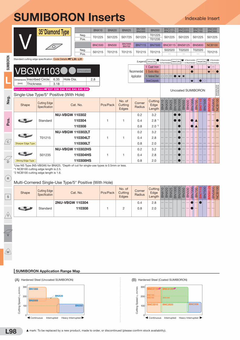
L98
SUMIBORON Application Range Map
Indexable Insert
300
200
100
0Heavy InterruptedContinuous Interrupted
BNX20
BN1000
BN350
BN2000
Cu
ttin
g S
peed
vc
( m/m
in) 300
200
100
0Heavy InterruptedContinuous Interrupted
BNC2010 BNC2020
BNC160
BNC100
BNC200
BNC2115 BNC2125
BNC300
Cu
ttin
g S
peed
vc
( m/m
in)
(A) Hardened Steel (Uncoated SUMIBORON) (B) Hardened Steel (Coated SUMIBORON)
SUMI
BORO
N
L
Neg
. P
os.
C
D
R
S
T
V
W
F mark: To be replaced by a new product, made to order, or discontinued (please confirm stock availability).
BNX10 BNX20 BNX25BN1000BN2000 BN350
BNC2115BNC2125
BNC2010BNC2020
BNC100BNC160
BNC200BNC300
Neg. T01225 S01225 S01725 S01225
T01225S01225 S01225 S01225 S01225
Pos. T01235
BNC500 BN500BN7000BN700 BN7115 BN7500 BNC8115 BNS8125 BNS800 NCB100
Neg.S01215 T01215 T01215 T01215 T01215
S02020 T02020 T02020T01215
Pos. Q Q Q
(Legend) Continuous Cutting : 1st Recommendation
General Cutting : 1st Recommendation
Interrupted Cutting : 1st Recommendation
: 2nd Recommendation : 2nd Recommendation : 2nd Recommendation
Recommended
Application
K Cast Iron
S Exotic Alloy
H Hardened Steel
Sintered Components
Multi-Cornered Single-Use Type/5° Positive (With Hole)
ShapeCutting Edge
SpecificationCat. No. Pcs/Pack
No. of
Cutting
Edges
Corner
Radius
Cutting
Edge
Length BN
X1
0
BN
X2
0
BN
X2
5
BN
10
00
BN
20
00
BN
35
0
BN
50
0
BN
70
00
BN
70
0
BN
71
15
BN
75
00
BN
S8125
BN
S8
00
NC
B1
00
Standard
2NU-VBGW 110304
1 2
0.4 2.8 Q Q Q Q Q D Q D Q Q
2NU-VBGW 110308 0.8 2.0 Q Q Q Q Q D Q Q Q
SUMIBORON Inserts
Single-Use Type/5° Positive (With Hole)
Uncoated SUMIBORON
BIN
DE
RLE
SS
S
UM
IBO
RO
N
ShapeCutting Edge
SpecificationCat. No. Pcs/Pack
No. of
Cutting
Edges
Corner
Radius
Cutting
Edge
Length BN
X1
0
BN
X2
0
BN
X2
5
BN
10
00
BN
20
00
BN
35
0
BN
50
0
BN
70
00
BN
70
0
BN
71
15
BN
75
00
BN
S8125
BN
S8
00
NC
B1
00
Standard
NU-VBGW 110302
1 1
0.2 3.2 D D Q Q
NU-VBGW 110304 0.4 2.8 *1 D D D F Q Q D
NU-VBGW 110308 0.8 2.0 *2 D D F Q Q D
Sharper Edge Type
T01215
NU-VBGW 110302LT
1 1
0.2 3.2 Q Q Q Q D Q Q Q Q Q Q Q Q Q
NU-VBGW 110304LT 0.4 2.8 Q Q Q Q D Q Q Q Q Q Q Q Q Q
NU-VBGW 110308LT 0.8 2.0 Q Q Q Q D Q Q Q Q Q Q Q Q Q
Strong Edge Type
S01235
NU-VBGW 110302HS
1 1
0.2 3.2 Q Q Q Q D Q Q Q Q Q Q Q Q
NU-VBGW 110304HS 0.4 2.8 Q Q Q Q D Q Q Q Q Q Q Q Q
NU-VBGW 110308HS 0.8 2.0 Q Q Q Q D Q Q Q Q Q Q Q Q
*Use NS Type (NS-VBGW) for BNX25. *Depth of cut for single-use types is 0.5mm or less.
*1 NCB100 cutting edge length is 2.5.
*2 NCB100 cutting edge length is 1.6.
V35° Diamond Type
VBGW1103DD Uncoated
Dimensions
(mm)
Inscribed Circle 6.35 Hole Dia. 2.8
Thickness 3.18
Standard cutting edge specification Code Details L30, L31
Applicable Internal Holders E37, E39, E40, E42, E43, E45, E46

L99
SUMIBORON Application Range Map
(D) Ductile Cast Iron (G) Titanium Alloy
Indexable Insert
0 1.0 2.0 3.0
300
500
200
400
Depth of Cut ap (mm)
BNC500
BNC8115
BNS8125BN7000
Cutt
ing
Sp
eed
vc
( m/m
in)
100
200
300
Depth of Cut ap(mm)
Feed Rate f(mm/rev)
0 0.1
0.150.10.05 0.2 0.25 0.3
0.2 0.3 0.4 0.5
Finishing region
Roughing region
BN7500BN7115 BN7000
Cutt
ing
Sp
eed
vc
( m/m
in)
Depth of Cut ap(mm)
Feed Rate f(mm/rev)
0 0.1
0.150.10.05 0.2 0.25 0.3
0.2 0.3 0.4 0.5
100
200
300
Finishing region
Roughing region
BN7500BN7115 BN7000
Cutt
ing
Sp
eed
vc
( m/m
in)
0
100
200
300
0.05 0.10 0.15 0.20
Feed Rate f (mm/rev)
NCB100
Cutt
ing
Sp
eed
vc
( m/m
in)Finishing
regionRoughing region
0 1.0 2.0 3.0 4.0
1,000
2,000
2,500
500
1,500
Depth of Cut ap (mm)
BNS800
BN7000
BN500
BNC8115BNS8125
Cutt
ing
Sp
eed
vc
( m/m
in)
SUMIBORON
L
Neg
. P
os.
C
D
R
S
T
V
W
(C) Gray Cast Iron (E) General Sintered Alloy (F) High-density Sintered Alloy
S mark: Stock or planned stock (please confirm stock availability)
(Legend) Continuous Cutting : 1st Recommendation
General Cutting : 1st Recommendation
Interrupted Cutting : 1st Recommendation
: 2nd Recommendation : 2nd Recommendation : 2nd Recommendation
Recommended
Application
K Cast Iron
S Exotic Alloy
H Hardened Steel
Sintered Components
SUMIBORON Inserts
Multi-Cornered Single-Use Type/5° Positive (With Hole)
Coated SUMIBORON
ShapeCutting Edge
SpecificationCat. No. Pcs/Pack
No. of
Cutting
Edges
Corner
Radius
Cutting
Edge
Length
BN
C2
11
5
BN
C2
12
5
BN
C2
01
0
BN
C2
02
0
BN
C3
00
BN
C1
00
BN
C1
60
BN
C2
00
BN
C5
00
BN
C8
11
5
Standard
2NC-VBGW 110302
1 2
0.2 3.2 S S D D Q
2NC-VBGW 110304 0.4 2.8 S S D D D Q
2NC-VBGW 110308 0.8 2.0 S S D D D Q
Sharper Edge Type
T00515
2NC-VBGW 110302LT
1 2
0.2 3.2 Q Q Q D Q Q Q Q Q Q
2NC-VBGW 110304LT 0.4 2.8 Q Q Q D Q Q Q Q Q Q
Sharper Edge Type
BNC2115 S00515
BNC2125 S00515
BNC100 S01715
BNC160 S01020
BNC200 S01015
BNC300 S00515
2NC-VBGW 110302LS
1 2
0.2 3.2 S S Q
2NC-VBGW 110304LS 0.4 2.8 S S Q
2NC-VBGW 110308LS 0.8 2.0 S S Q
V35° Diamond Type
VBGW1103DD Coated
Dimensions
(mm)
Inscribed Circle 6.35 Hole Dia. 2.8
Thickness 3.18
Applicable Internal Holders E37, E39, E40, E42, E43, E45, E46

L100
Indexable Insert
SUMIBORON Application Range Map
300
200
100
0Heavy InterruptedContinuous Interrupted
BNX20
BN1000
BN350
BN2000
Cu
ttin
g S
peed
vc
( m/m
in) 300
200
100
0Heavy InterruptedContinuous Interrupted
BNC2010 BNC2020
BNC160
BNC100
BNC200
BNC2115 BNC2125
BNC300
Cu
ttin
g S
peed
vc
( m/m
in)
(A) Hardened Steel (Uncoated SUMIBORON) (B) Hardened Steel (Coated SUMIBORON)
SUMI
BORO
N
L
Neg
.P
os.
C
D
R
S
T
V
W
BNX10 BNX20 BNX25BN1000BN2000 BN350
BNC2115BNC2125
BNC2010BNC2020
BNC100BNC160
BNC200BNC300
Neg.T01225 S01225 S01725 S01225
T01225S01225 S01225 S01225 S01225
Pos. T01235
BNC500 BN500BN7000BN700 BN7115 BN7500 BNC8115 BNS8125 BNS800 NCB100
Neg.S01215 T01215 T01215 T01215 T01215
S02020 T02020 T02020T01215
Pos. Q Q Q
(Legend) Continuous Cutting : 1st Recommendation
General Cutting : 1st Recommendation
Interrupted Cutting : 1st Recommendation
: 2nd Recommendation : 2nd Recommendation : 2nd Recommendation
Recommended
Application
K Cast Iron
S Exotic Alloy
H Hardened Steel
Sintered Components
SUMIBORON Inserts
Single-Use Type/5° Positive (With Hole)Uncoated SUMIBORON
BIN
DE
RLE
SS
S
UM
IBO
RO
N
ShapeCutting Edge
SpecificationCat. No. Pcs/Pack
No. of
Cutting
Edges
Corner
Radius
Cutting
Edge
Length BN
X1
0
BN
X2
0
BN
X2
5
BN
10
00
BN
20
00
BN
35
0
BN
50
0
BN
70
00
BN
70
0
BN
71
15
BN
75
00
BN
S8125
BN
S8
00
NC
B1
00
Standard
NU-VBGW 160402
1 1
0.2 3.8 Q D D Q Q
NU-VBGW 160404 0.4 3.3 *1 Q D D Q Q D
NU-VBGW 160408 0.8 2.5 *2 Q D D Q Q D
Sharper Edge Type
T01215
NU-VBGW 160402LT
1 1
0.2 3.8 Q Q Q Q D Q Q Q Q Q Q Q Q Q
NU-VBGW 160404LT 0.4 3.3 Q Q Q Q D Q Q Q Q Q Q Q Q Q
NU-VBGW 160408LT 0.8 2.5 Q Q Q Q D Q Q Q Q Q Q Q Q Q
Strong Edge Type
S01235
NU-VBGW 160404HS
1 1
0.4 3.3 Q Q Q Q D Q Q Q Q Q Q Q Q
NU-VBGW 160408HS 0.8 2.5 Q Q Q Q D Q Q Q Q Q Q Q Q
*Depth of cut for single-use types is 0.5mm or less.
*1 NCB100 cutting edge length is 2.5.
*2 NCB100 cutting edge length is 1.6.
Multi-Cornered Single-Use Type/5° Positive (With Hole)
ShapeCutting Edge
SpecificationCat. No. Pcs/Pack
No. of
Cutting
Edges
Corner
Radius
Cutting
Edge
Length BN
X1
0
BN
X2
0
BN
X2
5
BN
10
00
BN
20
00
BN
35
0
BN
50
0
BN
70
00
BN
70
0
BN
71
15
BN
75
00
BN
S8125
BN
S8
00
NC
B1
00
Standard
2NU-VBGW 160404
1 2
0.4 3.3 Q Q Q Q Q D Q D Q Q
2NU-VBGW 160408 0.8 2.5 Q Q Q Q Q D Q D Q Q
*Depth of cut for single-use types is 0.5mm or less.
V35° Diamond Type
VBGW1604DD Uncoated
Dimensions
(mm)
Inscribed Circle 9.525 Hole Dia. 4.4
Thickness 4.76
Applicable Internal Holders E14, E37, E39, E42, E45
Standard cutting edge specification Code Details L30, L31

L101
Indexable Insert
SUMIBORON Application Range Map
(D) Ductile Cast Iron (G) Titanium Alloy
0 1.0 2.0 3.0
300
500
200
400
Depth of Cut ap (mm)
BNC500
BNC8115
BNS8125BN7000
Cutt
ing
Sp
eed
vc
( m/m
in)
100
200
300
Depth of Cut ap(mm)
Feed Rate f(mm/rev)
0 0.1
0.150.10.05 0.2 0.25 0.3
0.2 0.3 0.4 0.5
Finishing region
Roughing region
BN7500BN7115 BN7000
Cutt
ing
Sp
eed
vc
( m/m
in)
Depth of Cut ap(mm)
Feed Rate f(mm/rev)
0 0.1
0.150.10.05 0.2 0.25 0.3
0.2 0.3 0.4 0.5
100
200
300
Finishing region
Roughing region
BN7500BN7115 BN7000
Cutt
ing
Sp
eed
vc
( m/m
in)
0
100
200
300
0.05 0.10 0.15 0.20
Feed Rate f (mm/rev)
NCB100
Cutt
ing
Sp
eed
vc
( m/m
in)Finishing
regionRoughing region
0 1.0 2.0 3.0 4.0
1,000
2,000
2,500
500
1,500
Depth of Cut ap (mm)
BNS800
BN7000
BN500
BNC8115BNS8125
Cutt
ing
Sp
eed
vc
( m/m
in)
SUMIBORON
L
Neg
.P
os.
C
D
R
S
T
V
W
(C) Gray Cast Iron (E) General Sintered Alloy (F) High-density Sintered Alloy
Recommended
Application
K Cast Iron
S Exotic Alloy
H Hardened Steel
Sintered Components
(Legend) Continuous Cutting : 1st Recommendation
General Cutting : 1st Recommendation
Interrupted Cutting : 1st Recommendation
: 2nd Recommendation : 2nd Recommendation : 2nd Recommendation
Recommended
Application
K Cast Iron
S Exotic Alloy
H Hardened Steel
Sintered Components
SUMIBORON Inserts
Multi-Cornered Single-Use Type/5° Positive (With Hole)Coated SUMIBORON
ShapeCutting Edge
SpecificationCat. No. Pcs/Pack
No. of
Cutting
Edges
Corner
Radius
Cutting
Edge
Length
BN
C2
11
5
BN
C2
12
5
BN
C2
01
0
BN
C2
02
0
BN
C3
00
BN
C1
00
BN
C1
60
BN
C2
00
BN
C5
00
BN
C8
11
5
Standard
2NC-VBGW 160402
1 2
0.2 3.8 S S D D Q
2NC-VBGW 160404 0.4 3.3 S S D D D Q
2NC-VBGW 160408 0.8 2.5 S S D D D Q
Low Cutting Force
Honing
2NC-VBGW 160402LE
1 2
0.2 3.8 Q Q D Q Q Q Q Q Q Q
2NC-VBGW 160404LE 0.4 3.3 Q Q D Q Q Q Q Q Q Q
2NC-VBGW 160408LE 0.8 2.5 Q Q D Q Q Q Q Q Q Q
Sharper Edge Type
T00515
2NC-VBGW 160402LT
1 2
0.2 3.8 Q Q Q D Q Q Q Q Q Q
2NC-VBGW 160404LT 0.4 3.3 Q Q Q D Q Q Q Q Q Q
2NC-VBGW 160408LT 0.8 2.5 Q Q Q D Q Q Q Q Q Q
BNC2115 S00515
BNC2125 S00515
BNC100 S01715
BNC160 S01020
BNC200 S01015
BNC300 S00515
2NC-VBGW 160402LS
1 2
0.2 3.8 S S Q
2NC-VBGW 160404LS 0.4 3.3 S S Q
2NC-VBGW 160408LS 0.8 2.5 S S Q
Sharper Edge Type
V35° Diamond Type
VBGW1604DD Coated
Dimensions
(mm)
Inscribed Circle 9.525 Hole Dia. 4.4
Thickness 4.76
Applicable Internal Holders E14, E37, E39, E42, E45
S mark: Stock or planned stock (please confirm stock availability)

L102
Indexable Insert
SUMIBORON Application Range Map
300
200
100
0Heavy InterruptedContinuous Interrupted
BNX20
BN1000
BN350
BN2000
Cu
ttin
g S
peed
vc
( m/m
in) 300
200
100
0Heavy InterruptedContinuous Interrupted
BNC2010 BNC2020
BNC160
BNC100
BNC200
BNC2115 BNC2125
BNC300
Cu
ttin
g S
peed
vc
( m/m
in)
(A) Hardened Steel (Uncoated SUMIBORON) (B) Hardened Steel (Coated SUMIBORON)
SUMI
BORO
N
L
Neg
.P
os.
C
D
R
S
T
V
W
Recommended
Application
K Cast Iron
S Exotic Alloy
H Hardened Steel
Sintered Components
BNX10 BNX20 BNX25BN1000BN2000 BN350
BNC2115BNC2125
BNC2010BNC2020
BNC100BNC160
BNC200BNC300
Neg.T01225 S01225 S01725 S01225
T01225S01225 S01225 S01225 S01225
Pos. T01235
BNC500 BN500BN7000BN700 BN7115 BN7500 BNC8115 BNS8125 BNS800 NCB100
Neg.S01215 T01215 T01215 T01215 T01215
S02020 T02020 T02020T01215
Pos. Q Q Q
(Legend) Continuous Cutting : 1st Recommendation
General Cutting : 1st Recommendation
Interrupted Cutting : 1st Recommendation
: 2nd Recommendation : 2nd Recommendation : 2nd Recommendation
Recommended
Application
K Cast Iron
S Exotic Alloy
H Hardened Steel
Sintered Components
SUMIBORON Inserts
Single-Use Type/7° Positive (With Hole)Uncoated SUMIBORON
BIN
DE
RLE
SS
S
UM
IBO
RO
N
ShapeCutting Edge
SpecificationCat. No. Pcs/Pack
No. of
Cutting
Edges
Corner
Radius
Cutting
Edge
Length BN
X1
0
BN
X2
0
BN
X2
5
BN
10
00
BN
20
00
BN
35
0
BN
50
0
BN
70
00
BN
70
0
BN
71
15
BN
75
00
BN
S8125
BN
S8
00
NC
B1
00
Standard
NU-VCGW 080202
1 1
0.2 3.3 Q D Q Q
NU-VCGW 080204 0.4 2.8 Q D Q Q
NU-VCGW 080208 0.8 2.0 Q D Q Q
Sharper Edge Type
T01215
NU-VCGW 080202LT
1 1
0.2 3.3 Q Q Q Q D Q Q Q Q Q Q Q Q Q
NU-VCGW 080204LT 0.4 2.8 Q Q Q Q D Q Q Q Q Q Q Q Q Q
NU-VCGW 080208LT 0.8 2.0 Q Q Q Q D Q Q Q Q Q Q Q Q Q
Strong Edge Type
S01235
NU-VCGW 080204HS
1 1
0.4 2.8 Q Q Q Q D Q Q Q Q Q Q Q Q
NU-VCGW 080208HS 0.8 2.0 Q Q Q Q D Q Q Q Q Q Q Q Q
*Depth of cut for single-use types is 0.5mm or less.
Multi-Cornered Single-Use Type/7° Positive (With Hole)Coated SUMIBORON
ShapeCutting Edge
SpecificationCat. No. Pcs/Pack
No. of
Cutting
Edges
Corner
Radius
Cutting
Edge
Length
BN
C2
11
5
BN
C2
12
5
BN
C2
01
0
BN
C2
02
0
BN
C3
00
BN
C1
00
BN
C1
60
BN
C2
00
BN
C5
00
BN
C8
11
5
Standard
2NC-VCGW 080202
1 2
0.2 3.3 D D Q
2NC-VCGW 080204 0.4 2.8 D D Q
V35° Diamond Type
Standard cutting edge specification Code Details L30, L31
VCGW0802DD Uncoated
Dimensions
(mm)
Inscribed Circle 4.76 Hole Dia. 2.3
Thickness 2.38
Applicable Internal Holders E38, E41, E44, E47
VCGW0802DD Coated
Dimensions
(mm)
Inscribed Circle 4.76 Hole Dia. 2.3
Thickness 2.38
Applicable Internal Holders E38, E41, E44, E47
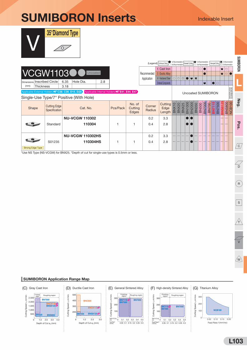
L103
Indexable Insert
SUMIBORON Application Range Map
(D) Ductile Cast Iron (G) Titanium Alloy
0 1.0 2.0 3.0
300
500
200
400
Depth of Cut ap (mm)
BNC500
BNC8115
BNS8125BN7000
Cutt
ing
Sp
eed
vc
( m/m
in)
100
200
300
Depth of Cut ap(mm)
Feed Rate f(mm/rev)
0 0.1
0.150.10.05 0.2 0.25 0.3
0.2 0.3 0.4 0.5
Finishing region
Roughing region
BN7500BN7115 BN7000
Cutt
ing
Sp
eed
vc
( m/m
in)
Depth of Cut ap(mm)
Feed Rate f(mm/rev)
0 0.1
0.150.10.05 0.2 0.25 0.3
0.2 0.3 0.4 0.5
100
200
300
Finishing region
Roughing region
BN7500BN7115 BN7000
Cutt
ing
Sp
eed
vc
( m/m
in)
0
100
200
300
0.05 0.10 0.15 0.20
Feed Rate f (mm/rev)
NCB100
Cutt
ing
Sp
eed
vc
( m/m
in)Finishing
regionRoughing region
0 1.0 2.0 3.0 4.0
1,000
2,000
2,500
500
1,500
Depth of Cut ap (mm)
BNS800
BN7000
BN500
BNC8115BNS8125
Cutt
ing
Sp
eed
vc
( m/m
in)
SUMIBORON
L
Neg
.P
os.
C
D
R
S
T
V
W
(C) Gray Cast Iron (E) General Sintered Alloy (F) High-density Sintered Alloy
(Legend) Continuous Cutting : 1st Recommendation
General Cutting : 1st Recommendation
Interrupted Cutting : 1st Recommendation
: 2nd Recommendation : 2nd Recommendation : 2nd Recommendation
Recommended
Application
K Cast Iron
S Exotic Alloy
H Hardened Steel
Sintered Components
SUMIBORON Inserts
Single-Use Type/7° Positive (With Hole)Uncoated SUMIBORON
BIN
DE
RLE
SS
S
UM
IBO
RO
N
ShapeCutting Edge
SpecificationCat. No. Pcs/Pack
No. of
Cutting
Edges
Corner
Radius
Cutting
Edge
Length BN
X1
0
BN
X2
0
BN
X2
5
BN
10
00
BN
20
00
BN
35
0
BN
50
0
BN
70
00
BN
70
0
BN
71
15
BN
75
00
BN
S8125
BN
S8
00
NC
B1
00
Standard
NU-VCGW 110302
1 1
0.2 3.3 D D Q Q
NU-VCGW 110304 0.4 2.8 D D Q Q
Strong Edge Type
S01235
NU-VCGW 110302HS
1 1
0.2 3.3 Q Q Q Q D Q Q Q Q Q Q Q Q
NU-VCGW 110304HS 0.4 2.8 Q Q Q Q D Q Q Q Q Q Q Q Q
*Use NS Type (NS-VCGW) for BNX25. *Depth of cut for single-use types is 0.5mm or less.
V35° Diamond Type
VCGW1103DD Uncoated
Dimensions
(mm)
Inscribed Circle 6.35 Hole Dia. 2.8
Thickness 3.18
Applicable Internal Holders E41, E44, E47Applicable External Holders C38, C39, D15, D28
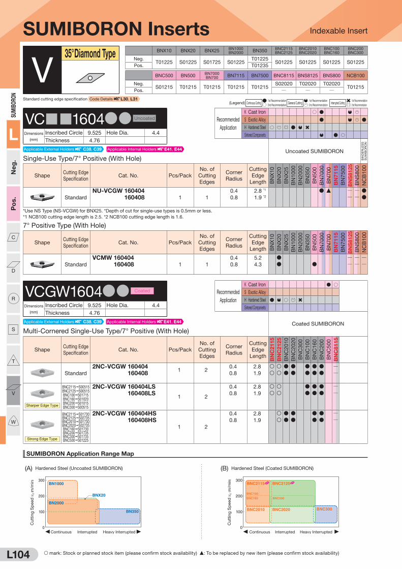
L104
Indexable Insert
SUMIBORON Application Range Map
300
200
100
0Heavy InterruptedContinuous Interrupted
BNX20
BN1000
BN350
BN2000
Cu
ttin
g S
peed
vc
( m/m
in) 300
200
100
0Heavy InterruptedContinuous Interrupted
BNC2010 BNC2020
BNC160
BNC100
BNC200
BNC2115 BNC2125
BNC300
Cu
ttin
g S
peed
vc
( m/m
in)
(A) Hardened Steel (Uncoated SUMIBORON) (B) Hardened Steel (Coated SUMIBORON)
SUMI
BORO
N
L
Neg
.P
os.
C
D
R
S
T
V
W
Recommended
Application
K Cast Iron
S Exotic Alloy
H Hardened Steel
Sintered Components
BNX10 BNX20 BNX25BN1000BN2000 BN350
BNC2115BNC2125
BNC2010BNC2020
BNC100BNC160
BNC200BNC300
Neg.T01225 S01225 S01725 S01225
T01225S01225 S01225 S01225 S01225
Pos. T01235
BNC500 BN500BN7000BN700 BN7115 BN7500 BNC8115 BNS8125 BNS800 NCB100
Neg.S01215 T01215 T01215 T01215 T01215
S02020 T02020 T02020T01215
Pos. Q Q Q
(Legend) Continuous Cutting : 1st Recommendation
General Cutting : 1st Recommendation
Interrupted Cutting : 1st Recommendation
: 2nd Recommendation : 2nd Recommendation : 2nd Recommendation
Recommended
Application
K Cast Iron
S Exotic Alloy
H Hardened Steel
Sintered Components
Multi-Cornered Single-Use Type/7° Positive (With Hole)
Coated SUMIBORON
ShapeCutting Edge
SpecificationCat. No. Pcs/Pack
No. of
Cutting
Edges
Corner
Radius
Cutting
Edge
Length
BN
C2
11
5
BN
C2
12
5
BN
C2
01
0
BN
C2
02
0
BN
C3
00
BN
C1
00
BN
C1
60
BN
C2
00
BN
C5
00
BN
C8
11
5
Standard
2NC-VCGW 1604041 2
0.4 2.8 S S D D D D D Q2NC-VCGW 160408 0.8 1.9 S S D D D D D Q
Sharper Edge Type
BNC2115 S00515BNC2125 S00515BNC100 S01715BNC160 S01020BNC200 S01015BNC300 S00515
2NC-VCGW 160404LS
1 2
0.4 2.8 S S D D D Q2NC-VCGW 160408LS 0.8 1.9 S S D D D Q
Strong Edge Type
BNC2115 S01730BNC2125 S02735BNC2010 S01730BNC2020 S02735BNC160 S01730BNC200 S01735BNC300 S01735BNC500 S01225
2NC-VCGW 160404HS
1 2
0.4 2.8 S D D D D Q2NC-VCGW 160408HS 0.8 1.9 S D D D D Q
SUMIBORON Inserts
Single-Use Type/7° Positive (With Hole)
Uncoated SUMIBORON
BIN
DE
RLE
SS
S
UM
IBO
RO
N
ShapeCutting Edge
SpecificationCat. No. Pcs/Pack
No. of
Cutting
Edges
Corner
Radius
Cutting
Edge
Length BN
X1
0
BN
X2
0
BN
X2
5
BN
10
00
BN
20
00
BN
35
0
BN
50
0
BN
70
00
BN
70
0
BN
71
15
BN
75
00
BN
S8125
BN
S8
00
NC
B1
00
Standard
NU-VCGW 1604041 1
0.4 2.8 *1 D F Q Q DNU-VCGW 160408 0.8 1.9 *2 Q Q D
*Use NS Type (NS-VCGW) for BNX25. *Depth of cut for single-use types is 0.5mm or less.
*1 NCB100 cutting edge length is 2.5. *2 NCB100 cutting edge length is 1.6.
7° Positive Type (With Hole)
ShapeCutting Edge
SpecificationCat. No. Pcs/Pack
No. of
Cutting
Edges
Corner
Radius
Cutting
Edge
Length BN
X1
0
BN
X2
0
BN
X2
5
BN
10
00
BN
20
00
BN
35
0
BN
50
0
BN
70
00
BN
70
0
BN
71
15
BN
75
00
BN
S8125
BN
S8
00
NC
B1
00
Standard
VCMW 1604041 1
0.4 5.2 D Q Q QVCMW 160408 0.8 4.3 D D Q Q Q
V35° Diamond Type
Standard cutting edge specification Code Details L30, L31
VC 1604DD Uncoated
Dimensions
(mm)
Inscribed Circle 9.525 Hole Dia. 4.4
Thickness 4.76
Applicable Internal Holders E41, E44Applicable External Holders C38, C39
VCGW1604DD Coated
Dimensions
(mm)
Inscribed Circle 9.525 Hole Dia. 4.4
Thickness 4.76
Applicable Internal Holders E41, E44Applicable External Holders C38, C39
S mark: Stock or planned stock item (please confirm stock availability) F: To be replaced by new item (please confirm stock availability)
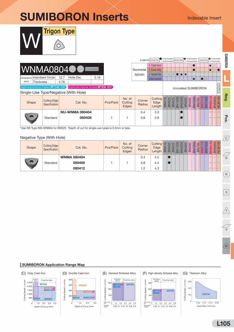
L105
Indexable Insert
SUMIBORON Application Range Map
(D) Ductile Cast Iron (G) Titanium Alloy
0 1.0 2.0 3.0
300
500
200
400
Depth of Cut ap (mm)
BNC500
BNC8115
BNS8125BN7000
Cutt
ing
Sp
eed
vc
( m/m
in)
100
200
300
Depth of Cut ap(mm)
Feed Rate f(mm/rev)
0 0.1
0.150.10.05 0.2 0.25 0.3
0.2 0.3 0.4 0.5
Finishing region
Roughing region
BN7500BN7115 BN7000
Cutt
ing
Sp
eed
vc
( m/m
in)
Depth of Cut ap(mm)
Feed Rate f(mm/rev)
0 0.1
0.150.10.05 0.2 0.25 0.3
0.2 0.3 0.4 0.5
100
200
300
Finishing region
Roughing region
BN7500BN7115 BN7000
Cutt
ing
Sp
eed
vc
( m/m
in)
0
100
200
300
0.05 0.10 0.15 0.20
Feed Rate f (mm/rev)
NCB100
Cutt
ing
Sp
eed
vc
( m/m
in)Finishing
regionRoughing region
0 1.0 2.0 3.0 4.0
1,000
2,000
2,500
500
1,500
Depth of Cut ap (mm)
BNS800
BN7000
BN500
BNC8115BNS8125
Cutt
ing
Sp
eed
vc
( m/m
in)
SUMIBORON
L
Neg
.P
os.
C
D
R
S
T
V
W
(C) Gray Cast Iron (E) General Sintered Alloy (F) High-density Sintered Alloy
(Legend) Continuous Cutting : 1st Recommendation
General Cutting : 1st Recommendation
Interrupted Cutting : 1st Recommendation
: 2nd Recommendation : 2nd Recommendation : 2nd Recommendation
Recommended
Application
K Cast Iron
S Exotic Alloy
H Hardened Steel
Sintered Components
Negative Type (With Hole)
ShapeCutting Edge
SpecificationCat. No. Pcs/Pack
No. of
Cutting
Edges
Corner
Radius
Cutting
Edge
Length BN
X1
0
BN
X2
0
BN
X2
5
BN
10
00
BN
20
00
BN
35
0
BN
50
0
BN
70
00
BN
70
0
BN
71
15
BN
75
00
BN
S8125
BN
S8
00
NC
B1
00
Standard
WNMA 080404
1 1
0.4 4.5 D Q Q Q
WNMA 080408 0.8 4.4 D Q Q Q
WNMA 080412 1.2 4.3 Q Q Q
SUMIBORON Inserts
Single-Use Type/Negative (With Hole)
Uncoated SUMIBORON
BIN
DE
RLE
SS
S
UM
IBO
RO
N
ShapeCutting Edge
SpecificationCat. No. Pcs/Pack
No. of
Cutting
Edges
Corner
Radius
Cutting
Edge
Length BN
X1
0
BN
X2
0
BN
X2
5
BN
10
00
BN
20
00
BN
35
0
BN
50
0
BN
70
00
BN
70
0
BN
71
15
BN
75
00
BN
S8125
BN
S8
00
NC
B1
00
Standard
NU-WNMA 080404
1 1
0.4 3.3 D Q Q Q
NU-WNMA 080408 0.8 2.8 D Q Q Q
*Use NS Type (NS-WNMA) for BNX25. *Depth of cut for single-use types is 0.5mm or less.
WTrigon Type
WNMA0804DD Uncoated
Dimensions
(mm)
Inscribed Circle 12.7 Hole Dia. 5.16
Thickness 4.76
Applicable Internal Holders E26, E27Applicable External Holders C40, C41
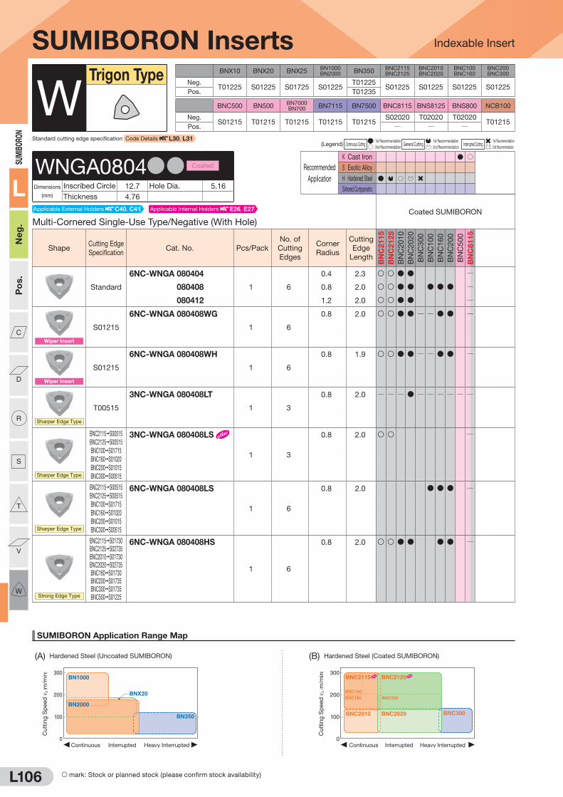
L106
Indexable Insert
SUMIBORON Application Range Map
300
200
100
0Heavy InterruptedContinuous Interrupted
BNX20
BN1000
BN350
BN2000
Cu
ttin
g S
peed
vc
( m/m
in) 300
200
100
0Heavy InterruptedContinuous Interrupted
BNC2010 BNC2020
BNC160
BNC100
BNC200
BNC2115 BNC2125
BNC300
Cu
ttin
g S
peed
vc
( m/m
in)
(A) Hardened Steel (Uncoated SUMIBORON) (B) Hardened Steel (Coated SUMIBORON)
SUMI
BORO
N
L
Neg
.P
os.
C
D
R
S
T
V
W
BNX10 BNX20 BNX25BN1000BN2000 BN350
BNC2115BNC2125
BNC2010BNC2020
BNC100BNC160
BNC200BNC300
Neg.T01225 S01225 S01725 S01225
T01225S01225 S01225 S01225 S01225
Pos. T01235
BNC500 BN500BN7000BN700 BN7115 BN7500 BNC8115 BNS8125 BNS800 NCB100
Neg.S01215 T01215 T01215 T01215 T01215
S02020 T02020 T02020T01215
Pos. Q Q Q
(Legend) Continuous Cutting : 1st Recommendation
General Cutting : 1st Recommendation
Interrupted Cutting : 1st Recommendation
: 2nd Recommendation : 2nd Recommendation : 2nd Recommendation
Recommended
Application
K Cast Iron
S Exotic Alloy
H Hardened Steel
Sintered Components
Multi-Cornered Single-Use Type/Negative (With Hole)
Coated SUMIBORON
ShapeCutting Edge
SpecificationCat. No. Pcs/Pack
No. of
Cutting
Edges
Corner
Radius
Cutting
Edge
Length
BN
C2
11
5
BN
C2
12
5
BN
C2
01
0
BN
C2
02
0
BN
C3
00
BN
C1
00
BN
C1
60
BN
C2
00
BN
C5
00
BN
C8
11
5
Standard
6NC-WNGA 080404
1 6
0.4 2.3 S S D D Q
6NC-WNGA 080408 0.8 2.0 S S D D D D D Q
6NC-WNGA 080412 1.2 2.0 S S D D Q
Wiper Insert
S01215
6NC-WNGA 080408WG
1 6
0.8 2.0 S S D D Q Q D D Q
Wiper Insert
S01215
6NC-WNGA 080408WH
1 6
0.8 1.9 S S D D Q Q D D Q
Sharper Edge Type
T00515
3NC-WNGA 080408LT
1 3
0.8 2.0 Q Q Q D Q Q Q Q Q Q
Sharper Edge Type
BNC2115 S00515
BNC2125 S00515
BNC100 S01715
BNC160 S01020
BNC200 S01015
BNC300 S00515
3NC-WNGA 080408LS
1 3
0.8 2.0 S S Q
Sharper Edge Type
BNC2115 S00515
BNC2125 S00515
BNC100 S01715
BNC160 S01020
BNC200 S01015
BNC300 S00515
6NC-WNGA 080408LS
1 6
0.8 2.0 D D D Q
Strong Edge Type
BNC2115 S01730BNC2125 S02735BNC2010 S01730BNC2020 S02735BNC160 S01730BNC200 S01735BNC300 S01735BNC500 S01225
6NC-WNGA 080408HS
1 6
0.8 2.0 S S D D D D Q
SUMIBORON Inserts
WTrigon Type
Standard cutting edge specification Code Details L30, L31
WNGA0804DD Coated
Dimensions
(mm)
Inscribed Circle 12.7 Hole Dia. 5.16
Thickness 4.76
S mark: Stock or planned stock (please confirm stock availability)
Applicable Internal Holders E26, E27Applicable External Holders C40, C41

L107
Indexable Insert
SUMIBORON Application Range Map
(D) Ductile Cast Iron (G) Titanium Alloy
0 1.0 2.0 3.0
300
500
200
400
Depth of Cut ap (mm)
BNC500
BNC8115
BNS8125BN7000
Cutt
ing
Sp
eed
vc
( m/m
in)
100
200
300
Depth of Cut ap(mm)
Feed Rate f(mm/rev)
0 0.1
0.150.10.05 0.2 0.25 0.3
0.2 0.3 0.4 0.5
Finishing region
Roughing region
BN7500BN7115 BN7000
Cutt
ing
Sp
eed
vc
( m/m
in)
Depth of Cut ap(mm)
Feed Rate f(mm/rev)
0 0.1
0.150.10.05 0.2 0.25 0.3
0.2 0.3 0.4 0.5
100
200
300
Finishing region
Roughing region
BN7500BN7115 BN7000
Cutt
ing
Sp
eed
vc
( m/m
in)
0
100
200
300
0.05 0.10 0.15 0.20
Feed Rate f (mm/rev)
NCB100
Cutt
ing
Sp
eed
vc
( m/m
in)Finishing
regionRoughing region
0 1.0 2.0 3.0 4.0
1,000
2,000
2,500
500
1,500
Depth of Cut ap (mm)
BNS800
BN7000
BN500
BNC8115BNS8125
Cutt
ing
Sp
eed
vc
( m/m
in)
SUMIBO
RON
L
Neg.
Pos.
C
D
R
S
T
V
W
(C) Gray Cast Iron (E) General Sintered Alloy (F) High-density Sintered Alloy
Recommended
Application
K Cast Iron
S Exotic Alloy
H Hardened Steel
Sintered Components
(Legend) Continuous Cutting : 1st Recommendation
General Cutting : 1st Recommendation
Interrupted Cutting : 1st Recommendation
: 2nd Recommendation : 2nd Recommendation : 2nd Recommendation
Recommended
Application
K Cast Iron
S Exotic Alloy
H Hardened Steel
Sintered Components
SUMIBORON Inserts
Single-Use Type/5° Positive (With Hole)
Uncoated SUMIBORON
BIN
DE
RLE
SS
S
UM
IBO
RO
N
ShapeCutting Edge
SpecificationCat. No. Pcs/Pack
No. of
Cutting
Edges
Corner
Radius
Cutting
Edge
Length BN
X1
0
BN
X2
0
BN
X2
5
BN
10
00
BN
20
00
BN
35
0
BN
50
0
BN
70
00
BN
70
0
BN
71
15
BN
75
00
BN
S8125
BN
S8
00
NC
B1
00
Low Cutting Force
Sharp
Edge
NU-WBEW 060102L-LF
1 1
0.2 1.3 Q Q Q Q Q Q Q D F Q Q Q
NU-WBEW 060104L-LF 0.4 1.2 Q Q Q Q Q Q Q Q Q Q
Sharper Edge Type
T00715
NU-WBEW 060102L-LT
1 1
0.2 1.3 Q D Q Q Q Q Q Q Q Q Q Q Q Q
NU-WBEW 060104L-LT 0.4 1.2 Q D Q Q Q Q Q Q Q Q Q Q Q Q
*Depth of cut for single-use types is 0.5mm or less.
Single-Use Type/5° Positive (With Hole)
Uncoated SUMIBORON
BIN
DE
RLE
SS
S
UM
IBO
RO
N
ShapeCutting Edge
SpecificationCat. No. Pcs/Pack
No. of
Cutting
Edges
Corner
Radius
Cutting
Edge
Length BN
X1
0
BN
X2
0
BN
X2
5
BN
10
00
BN
20
00
BN
35
0
BN
50
0
BN
70
00
BN
70
0
BN
71
15
BN
75
00
BN
S8125
BN
S8
00
NC
B1
00
Low Cutting Force
Sharp
Edge
NU-WBEW 080202L-LF
1 1
0.2 1.7 Q Q Q Q Q Q Q Q Q
NU-WBEW 080204L-LF 0.4 1.6 Q Q Q Q Q Q Q Q Q
Sharper Edge Type
T01215
NU-WBEW 080202L-LT
1 1
0.2 1.7 Q D Q Q Q Q Q Q Q Q Q Q Q Q
NU-WBEW 080204L-LT 0.4 1.6 Q D Q Q Q Q Q Q Q Q Q Q Q Q
*Depth of cut for single-use types is 0.5mm or less.
WTrigon Type
WBEW0601DD Uncoated
Dimensions
(mm)
Inscribed Circle 3.97 Hole Dia. 2.2
Thickness 1.59
Applicable Internal Holders E54
WBEW0802DD Uncoated
Dimensions
(mm)
Inscribed Circle 4.76 Hole Dia. 2.2
Thickness 2.38
Applicable Internal Holders E54
F mark: To be replaced by a new product, made to order, or discontinued (please confirm stock availability).
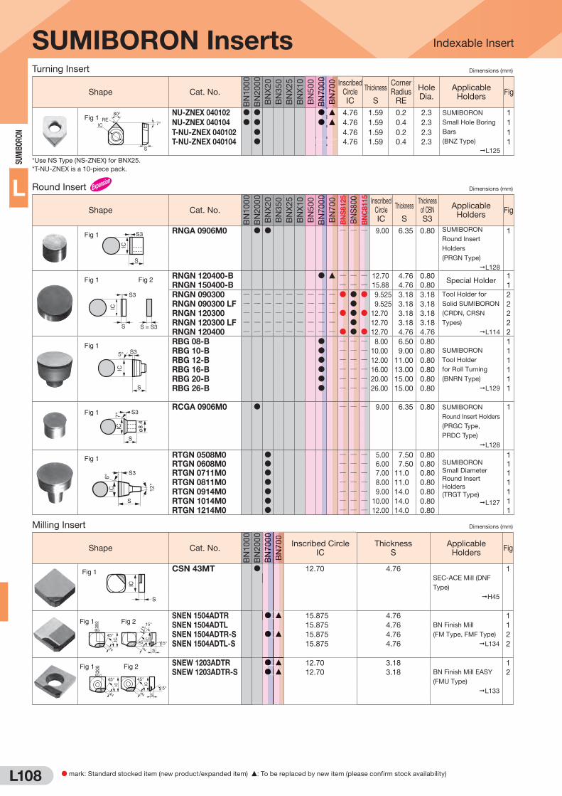
L108
SUM
IBO
RON
L
Milling Insert Dimensions (mm)
Shape Cat. No.
BN
1000
BN
2000
BN
7000
BN
700
Inscribed Circle IC
Thickness S
Applicable Holders
Fig
S
IC
Fig 1 CSN 43MT D 12.70 4.76
SEC-ACE Mill (DNF
Type)
H45
1
IC IC45°
45°
15°
15°
R30
0
22 S
Fig 2 Fig 1SNEN 1504ADTR D F 15.875 4.76
BN Finish Mill
(FM Type, FMF Type)
L134
1
SNEN 1504ADTL 15.875 4.76 1
SNEN 1504ADTR-S D F 15.875 4.76 2
SNEN 1504ADTL-S 15.875 4.76 2
45° 45°
15°
R30
0
2 2 S
IC IC
Fig 1 Fig 2
SNEW 1203ADTR D F 12.70 3.18
BN Finish Mill EASY
(FMU Type)
L133
1
SNEW 1203ADTR-S D F 12.70 3.18 2
Turning Insert Dimensions (mm)
Shape Cat. No.
BN
1000
BN
2000
BN
X20
BN
350
BN
X25
BN
X10
BN
500
BN
7000
BN
700 Inscribed
Circle IC
Thickness
S
Corner Radius
RE
Hole Dia.
Applicable Holders
Fig
80°
IC
S
RE7°
Fig 1NU-ZNEX 040102 D D D F 4.76 1.59 0.2 2.3 SUMIBORON
Small Hole Boring
Bars
(BNZ Type)
L125
1
NU-ZNEX 040104 D D D F 4.76 1.59 0.4 2.3 1
T-NU-ZNEX 040102 D 4.76 1.59 0.2 2.3 1
T-NU-ZNEX 040104 D 4.76 1.59 0.4 2.3 1
*Use NS Type (NS-ZNEX) for BNX25.
*T-NU-ZNEX is a 10-piece pack.
Round Insert Dimensions (mm)
Shape Cat. No.
BN
1000
BN
2000
BN
X20
BN
350
BN
X25
BN
X10
BN
500
BN
7000
BN
700
BN
S8
12
5
BN
S800
BN
C8
11
5
Inscribed Circle IC
Thickness
S
Thickness of CBN S3
Applicable Holders
Fig
IC
S
S3Fig 1 RNGA 0906M0 D D Q Q Q 9.00 6.35 0.80 SUMIBORON
Round Insert
Holders
(PRGN Type)
L128
1
IC
S
S3
Fig 1
S = S3
Fig 2 RNGN 120400-B D F Q Q Q 12.70 4.76 0.80Special Holder
1
RNGN 150400-B Q Q Q 15.88 4.76 0.80 1
RNGN 090300 Q Q Q Q Q Q Q Q Q D D D 9.525 3.18 3.18 Tool Holder for
Solid SUMIBORON
(CRDN, CRSN
Types)
L114
2
RNGN 090300 LF Q Q Q Q Q Q Q Q Q D 9.525 3.18 3.18 2
RNGN 120300 Q Q Q Q Q Q Q Q Q D D D 12.70 3.18 3.18 2
RNGN 120300 LF Q Q Q Q Q Q Q Q Q D 12.70 3.18 3.18 2
RNGN 120400 Q Q Q Q Q Q Q Q Q D D D 12.70 4.76 4.76 2
S
5°
IC
S3Fig 1 RBG 08-B D Q Q Q 8.00 6.50 0.80
SUMIBORON
Tool Holder
for Roll Turning
(BNRN Type)
L129
1
RBG 10-B D Q Q Q 10.00 9.00 0.80 1
RBG 12-B D Q Q Q 12.00 11.00 0.80 1
RBG 16-B D Q Q Q 16.00 13.00 0.80 1
RBG 20-B D Q Q Q 20.00 15.00 0.80 1
RBG 26-B D Q Q Q 26.00 15.00 0.80 1
S
IC ø8.
4
7°
S3Fig 1RCGA 0906M0 D Q Q Q 9.00 6.35 0.80 SUMIBORON
Round Insert Holders
(PRGC Type,
PRDC Type)
L128
1
S
IC6°
12°
S3
Fig 1 RTGN 0508M0 D Q Q Q 5.00 7.50 0.80SUMIBORON
Small Diameter
Round Insert
Holders
(TRGT Type)
L127
1
RTGN 0608M0 D Q Q Q 6.00 7.50 0.80 1
RTGN 0711M0 D Q Q Q 7.00 11.0 0.80 1
RTGN 0811M0 D Q Q Q 8.00 11.0 0.80 1
RTGN 0914M0 D Q Q Q 9.00 14.0 0.80 1
RTGN 1014M0 D Q Q Q 10.00 14.0 0.80 1
RTGN 1214M0 D Q Q Q 12.00 14.0 0.80 1
SUMIBORON Inserts
BN
BN
BN
70
70
7000
00
00
BN
BN
70
7000
DDDDDDFFFF
Indexable Insert
DDD
DDD
DDDDDD
FFF
FFF
FFFFFF
BN
BN
BN
70
70
7000
00
00
BN
BN
70
70
00
D mark: Standard stocked item (new product/expanded item) F: To be replaced by new item (please confirm stock availability)
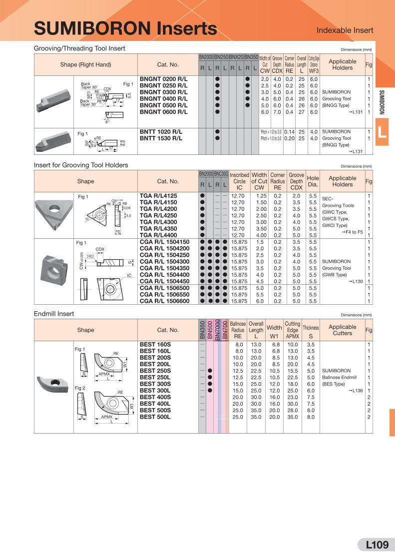
L109
SUM
IBORO
N
L
Grooving/Threading Tool Insert Dimensions (mm)
Shape (Right Hand) Cat. No.
BN2000 BN250 BNX20 BN350 Width of Cut
CW
Groove Depth CDX
Corner Radius RE
Overall Length L
Cutting Edge Distance WF3
Applicable Holders
FigR L R L R L R L
CDX
L
6°
17
WF3
RE
RE
5.5
CW±0.05
Back Taper 30'
Back Taper 30'
Fig 1BNGNT 0200 R/L D D 2.0 4.0 0.2 25 6.0
SUMIBORON
Grooving Tool
(BNGG Type)
L131
1
BNGNT 0250 R/L D D 2.5 4.0 0.2 25 6.0 1
BNGNT 0300 R/L D D 3.0 5.0 0.4 25 6.0 1
BNGNT 0400 R/L D D 4.0 6.0 0.4 26 6.0 1
BNGNT 0500 R/L D D 5.0 6.0 0.4 26 6.0 1
BNGNT 0600 R/L D 6.0 7.0 0.4 27 6.0 1
L
RE
WF360
°
6.0
17
Fig 1 BNTT 1020 R/L D Pitch = 1.0 to 2.0 0.14 25 4.0 SUMIBORON
Grooving Tool
(BNGG Type)
L131
1
BNTT 1530 R/L D Pitch = 1.5 to 3.0 0.20 25 4.0 1
Insert for Grooving Tool Holders Dimensions (mm)
Shape Cat. No.
BN2000 BNC30G Inscribed Circle IC
Width of Cut CW
Corner Radius
RE
Groove Depth CDX
Hole Dia.
Applicable Holders
FigR L R L
IC
CW±0.025
RERECDX
5.5
4.76
Fig 1 TGA R/L4125 D Q Q 12.70 1.25 0.2 2.0 5.5SEC-
Grooving Tools
(GWC Type,
GWCS Type,
GWCI Type)
F4 to F5
1
TGA R/L4150 D Q Q 12.70 1.50 0.2 3.5 5.5 1
TGA R/L4200 D Q Q 12.70 2.00 0.2 3.5 5.5 1
TGA R/L4250 D Q Q 12.70 2.50 0.2 4.0 5.5 1
TGA R/L4300 D Q Q 12.70 3.00 0.2 4.0 5.5 1
TGA R/L4350 D Q Q 12.70 3.50 0.2 5.0 5.5 1
TGA R/L4400 D Q Q 12.70 4.00 0.2 5.0 5.5 1
CDX
IC
2-R0.2
CW
±0.
025
S
Fig 1 CGA R/L 1504150 D D D D 15.875 1.5 0.2 3.5 5.5
SUMIBORON
Grooving Tool
(GWB Type)
L130
1
CGA R/L 1504200 D D D D 15.875 2.0 0.2 3.5 5.5 1
CGA R/L 1504250 D D D D 15.875 2.5 0.2 4.0 5.5 1
CGA R/L 1504300 D D D D 15.875 3.0 0.2 4.0 5.5 1
CGA R/L 1504350 D D D D 15.875 3.5 0.2 5.0 5.5 1
CGA R/L 1504400 D D D D 15.875 4.0 0.2 5.0 5.5 1
CGA R/L 1504450 D D D D 15.875 4.5 0.2 5.0 5.5 1
CGA R/L 1506500 D D D D 15.875 5.0 0.2 5.0 5.5 1
CGA R/L 1506550 D D D D 15.875 5.5 0.2 5.0 5.5 1
CGA R/L 1506600 D D D D 15.875 6.0 0.2 5.0 5.5 1
Endmill Insert Dimensions (mm)
Shape Cat. No.
BN
350
BN
500
BN
7000
BN
700 Ballnose
Radius RE
Overall Length
L
Width
W1
Cutting Edge APMX
Thickness S
Applicable Cutters
Fig
W1
L
RE
APMX
APMX
S
W1
L
RE
S
Fig 1
Fig 2
BEST 160S Q 8.0 13.0 6.8 10.0 3.5
SUMIBORON
Ballnose Endmill
(BES Type)
L136
1
BEST 160L Q 8.0 13.0 6.8 13.0 3.5 1
BEST 200S Q 10.0 20.0 8.5 13.0 4.5 1
BEST 200L Q 10.0 20.0 8.5 20.0 4.5 1
BEST 250S Q D 12.5 22.5 10.5 15.5 5.0 1
BEST 250L Q D 12.5 22.5 10.5 22.5 5.0 1
BEST 300S Q D 15.0 25.0 12.0 18.0 6.0 1
BEST 300L Q D 15.0 25.0 12.0 25.0 6.0 1
BEST 400S Q 20.0 30.0 16.0 23.0 7.5 2
BEST 400L Q 20.0 30.0 16.0 30.0 7.5 2
BEST 500S Q 25.0 35.0 20.0 28.0 8.0 2
BEST 500L Q 25.0 35.0 20.0 35.0 8.0 2
SUMIBORON Inserts Indexable Insert

L110
SUM
IBO
RON
L
SUMIBORON
Solid SUMIBORON Indexable Insert (Solid CBN Type)
BN
C8
11
5
BN
S8
12
5
BN
S8
00
Dimensions (mm)
Applicable Holders
Insc
ribed
Circ
le
Thic
kness
Cor
ner R
adiu
s
Ho
le Y
/N
Shape Cat. No.
80°
Diamond
Type
CNGN 090308 D D D
9.525 3.18
0.8
No External L113CNGN 090308LF DCNGN 090312 D D D
1.2CNGN 090312LF DCNGN 120408 D D D
12.70 4.76
0.8
No External L113CNGN 120412 D D D 1.2
CNGN 120416 D D D 1.6
CNGA 120408 Q Q D12.70 4.76
0.8
Yes
External C8 to C10
Internal E15 , E23 to E25CNGA 120412 Q Q D 1.2
CNGX 12040812.70 4.76
0.8
Dimple External L115CNGX 120412 D D D 1.2
CNGX 120416 D D D 1.6
55°
Diamond
Type
DNGN 110308 D D D
9.525 3.18
0.8
No External L113DNGN 110308LF DDNGN 110312 D D D
1.2DNGN 110312LF D
Round
Type
RNGN 090300 D D D9.525 3.18 Q No External L114RNGN 090300LF D
RNGN 120300 D D D12.70
3.18Q No External L114RNGN 120300LF D
RNGN 120400 D D D 4.76
Square
Type
SNGN 090308 D D D
9.525 3.18
0.8
No
External L112
Milling Cutters H210 L135
SNGN 090308LF DSNEN 090308W D D DSNEN 090308LFW DSNGN 090312 D D D
1.2SNGN 090312LF DSNGN 120308 D D D
12.70 3.18
0.8
No External L112SNGN 120308LF DSNGN 120312 D D D
1.2SNGN 120312LF DSNGN 120408 D D D
12.70 4.76
0.8
No External L112SNGN 120412 D D D 1.2
SNGN 120416 D D D 1.6
SNGN 120420 D D D 2.0
SNGA 120408 Q Q D12.70 4.76
0.8
Yes
External C19 to C24
Internal E51 to E53SNGA 120412 Q Q D 1.2
SNGX 12040812.70 4.76
0.8
Dimple External L115SNGX 120412 D D D 1.2
SNGX 120416 D D D 1.6
Triangular
Type
TNGN 110308 D D D
6.35 3.18
0.8
No External L112TNGN 110308LF DTNGN 110312 D D D
1.2TNGN 110312LF DTNGN 160408 D D D
9.525 4.76
0.8
No External L112TNGN 160412 D D D 1.2
TNGN 160416 D D D 1.6
TNGN 160420 D D D 2.0
TNGA 160408 Q Q D9.525 4.76
0.8
Yes
External C27 to C33External D16 D20Internal E15 , E61 to E63
TNGA 160412 Q Q D 1.2
*Part number suffix: LF: Sharp edge type W: Wiper type LFW: Wiper sharp edge type
Refer to pages L112 to L115 for solid
SUMIBORON dedicated holders.
K Cast IronApplications H Hardened Steel
DDD
DDD
DDDDDDDDDQQQQQQ
DDDDDDDDD
DDD
DDD
DDD
DDDDDD
DDD
DDD
DDD
DDD
DDDDDDDDDDDDQQQQQQ
DDDDDDDDD
DDD
DDDDDDDDDDDDQQQQQQ

L111
M E M O

L112
SUM
IBO
RON
L
SEC-
Tool Holders for Solid SUMIBORON
External TurningCSBN/FN11
WF
75°LF
Fig 1
BH
LH
HF
Fig 2
-6°
-5°
Figure shows right-hand (R) tool.
Holder Parts Dimensions (mm)
Cat. No.
Stock Height WidthOverall Length
Cutting Edge
Cutting Edge Height
HeadApplicable
InsertFig
Clamp Plate
ChipbreakerDouble Screw
Bolt ShimShim
RetainerSpring Wrench
R L H B LF WF HF LH
CSBN R/L2525-32 D 25 25 160 21.5 25 30 SNGN0903SS 1CCM8UL
CBS13WB8-22T Q
SSN0903
SPP3Q LT27
CSBN R/L2525-42 D 25 25 160 21.5 25 35 SNGN1203SS 1 CBS14SSND423
FN11 R/L-44A D D 25 25 160 21.5 25 33 SNGN1204SS 2 DCR/L1 CBD4R/L Q BH0830R/L DSP5 LH040
General Turning
Clamp-on
FacingCSKN
WF
WF215° LF
BHHF
LH
-5°
-6°
Fig 1
Figure shows right-hand (R) tool.
Holder Parts Dimensions (mm)
Cat. No.
Stock Height WidthOverall Length
Cutting Edge
Cutting Edge Height
Head OffsetApplicable
InsertFig
Clamp Plate
ChipbreakerDouble Screw
ShimShim
RetainerWrench
R L H B LF WF HF LH WF2
CSKN R/L2525-32 D 25 25 160 32 25 25 7 SNGN0903SS 1CCM8UL
CBS13WB8-22T
SSN0903SPP3 LT27
CSKN R/L2525-42 D 25 25 160 32 25 25 7 SNGN1203SS 1 CBS14 SSND423
Facing
Clamp-on
External TurningCTGN/FN21 Fig 1
Fig 2
B
HF H
WF
91°
LFWF2
LH
-6°
-5°
Figure shows right-hand (R) tool.
Holder Parts Dimensions (mm)
Cat. No.
Stock Height WidthOverall Length
Cutting Edge
Cutting Edge Height
Head OffsetApplicable
InsertFig
Clamp Plate
ChipbreakerDouble Screw
Bolt ShimShim
RetainerSpring Wrench
R L H B LF WF HF LH WF2
CTGN R/L2525-22 D 25 25 160 32 25 20 7 TNGN1103SS 1 CCM6UL CBT12 WB6-16T Q STN1103SPP3
Q LT20
FN21 R/L-44A D D 25 25 160 25 25 32 Q TNGN1604SS 2 DCR/L2 CBD4R/L Q BH0830R/L STND323 DSP5 LH040
General Turning
Clamp-on
Insert
(1) SNGN0903SS
(2) SNGN1203SS
(3) SNGN1204SS
Insert
(1) SNGN0903SS
(2) SNGN1203SS
Insert
(1) TNGN1103SS
(2) TNGN1604SS
75˚
75°
91˚
L110
L110
L110
D

L113
SUM
IBORO
N
L
SEC-
Tool Holders for Solid SUMIBORON
External Diameter/FacingCCLN/FCLN B
HHF
LF
WF
95°
WF2
LH
-5°
-5°
Fig 1Fig 2
Figure shows right-hand (R) tool.
Holder Parts Dimensions (mm)
Cat. No.
Stock Height WidthOverall Length
Cutting Edge
Cutting Edge Height
Head OffsetApplicable
InsertFig
Clamp Plate
ChipbreakerDouble Screw
ShimShim
RetainerWrench
R L H B LF WF HF LH WF2
CCLN R/L2525-32 D 25 25 150 32 25 25 7 CNGN0903SS 1 CCM8UL CBC0903 WB8-22T SCN0903SPP3
LT27
FCLN R/L2525-43 D D 25 25 150 32 25 30 7 CNGN1204SS 2 CCM8-LONG CBC4 WB8-30 SCND433 LH040
General Turning and Facing
Clamp-on
External Diameter/ProfilingCDJN Fig 1
WF B
WF2
HF H
LFLH
93°-5°
-5°
Figure shows right-hand (R) tool.
Holder Parts Dimensions (mm)
Cat. No.
Stock Height WidthOverall Length
Cutting Edge
Cutting Edge Height
Head OffsetApplicable
InsertFig
Clamp Plate
ChipbreakerDouble Screw
ShimShim
RetainerWrench
R L H B LF WF HF LH WF2
CDJN R/L2525-32 D 25 25 150 32 25 30 7 DNGN1103SS 1 CCM8UL CBD1103 WB8-22T SDN1103 SPP3 LT27
General Turning and Profiling
Clamp-on
Insert
(1) CNGN0903SS
(2) CNGN1204SS
Insert
(1) DNGN1103SS
95˚
95˚
93°
L110
L110

L114
SUM
IBO
RON
L
SEC-
Tool Holders for Solid SUMIBORON
External Diameter/ProfilingCRDN Fig 1
CDX
LHLF
BHHF
0°
IC
-6°
Holder Parts Dimensions (mm)
Cat. No.
Sto
ck
Inscribed
CircleHeight Width
Overall
Length
Cutting Edge
HeightHead
Depth of
CutApplicable
InsertFig
Clamp
Plate
Double
ScrewShim
Shim
RetainerWrench
IC H B LF HF LH CDX
CRDN N2525-32 D 9.525 25 25 150 25 35 15 RNGN090300 1
CCM8-LONG WB8-22T
SRND32
SPP3 LT27CRDN N2525-42 D 12.7 25 25 150 25 35 20 RNGN120300 1SRND42
CRDN N2525-43 D 12.7 25 25 150 25 35 20 RNGN120400 1
General Turning and Profiling
Clamp-on
External Diameter/FacingCRSN Fig 1
BHHF
LF
LH
WF
-6°
-6°
IC
WF2
Figure shows right-hand (R) tool.
Holder Parts Dimensions (mm)
Cat. No.
StockInscribed
CircleHeight Width
Overall
Length
Cutting
Edge
Cutting Edge
HeightHead Offset
Applicable
InsertFig
Clamp
Plate
Double
ScrewShim
Shim
RetainerWrench
R L IC H B LF WF HF LH WF2
CRSN R/L2525-32 D 9.525 25 25 150 32 25 30 7 RNGN090300 1
CCM8-LONG WB8-22T
SRND32
SPP3 LT27CRSN R/L2525-42 D 12.7 25 25 150 32 25 30 7 RNGN120300 1SRND42
CRSN R/L2525-43 D 12.7 25 25 150 32 25 30 7 RNGN120400 1
General Turning and Face Grooving
Clamp-on
Insert
(1) RNGN090300
(2) RNGN120300
(3) RNGN120400
Insert
(1) RNGN090300
(2) RNGN120300
(3) RNGN120400
L110
L110

L115
SUM
IBORO
N
L
SEC-
Tool Holders for Solid SUMIBORON
External TurningXSBN Fig 1
BH
75° LFLH
WF
HF
-6°
-5°
Figure shows right-hand (R) tool.
Holder Parts Dimensions (mm)
Cat. No.
StockHeight Width
Overall
Length
Cutting
Edge
Cutting Edge
HeightHead Applicable
InsertFig
Clamp Plate Bolt Shim Shim Retainer Spring Wrench
R LH B LF WF HF LH
XSBN R/L2525-43 D 25 25 150 21.5 25 38 SNGX1204SS 1 DSLX8 BH0825 SSND433 SPP3 GSP10 LH050
General Turning
Dimple Lock
External Diameter/FacingXCLN Fig 1
BH
WF
HF
LFLH
5°
WF2
-5°
-5°
Figure shows right-hand (R) tool.
Holder Parts Dimensions (mm)
Cat. No.
StockHeight Width
Overall
Length
Cutting
Edge
Cutting Edge
HeightHead Offset
Applicable
InsertFig
Clamp Plate Bolt Shim Shim Retainer Spring Wrench
R LH B LF WF HF LH WF2
XCLN R/L2525-43 D 25 25 150 32 25 33 7 CNGX1204SS 1 DSLX8 BH0825 SCND433 SPP3 GSP10 LH050
General Turning and Facing
Dimple Lock
Insert
(1) SNGX1204SS
Insert
(1) CNGX1204SS
75˚
95˚
95˚
L110
L110

L116
SUM
IBO
RON
L
SUMIBORON
Inserts & Special Holders for High-efficiency Machining
Features
D Improved finished surface roughness with high-feed
cutting
D Ideal for profiling when surface roughness is required
D Operation with different corner radius
fGood Surface Roughness
Large Corner Radius
Small Corner Radius
Feed Rate
f Feed Rate
Work Material
Work Material
Larg
e C
orn
er
Rad
ius
Sm
all
Co
rner
Rad
ius
f
Same surface roughness at
approx. double the efficiency
Theoretical Surface
Roughness 1/3 or Less
Theoretical surface roughness 1/3 or lower
Same surface roughness at approx. double the efficiency
* Actual value of surface roughness is approximately 1.5 to 3 times higher (for steel).
* Theoretical surface roughness is calculated using the following formula: [h = (f2 / 8r) x 103].
Corner Radius
Feed Rate
Corner Radius 0.8mm vs. 2.4mm Comparison
Corner Radius 0.8mm vs. 2.4mm Comparison
Feed Rate
Required Theoretical Surface Roughness
μm
Th
eo
retical S
urf
ace R
ou
gh
ness h
(μ
m)
D Cutting force comparison with different corner radius
ffff
Inserts with a larger corner radius also give better surface roughness during actual machining
Good Surface Roughness
Work Material: SCM415H (60HRC)
Cutting Conditions: vc = 100m/min, ap = 0.1mm Dry
Wiper
Wiper Insert
Su
rface R
ou
gh
ness R
z (
μm
)
Low cutting force compared to wiper insert enables high-feed cutting
Wiper
Work Material: SCM415H (60HRC)
Cutting Conditions: vc = 150m/min, f = 0.3mm/rev, ap = 0.1mm Dry
Wiper Insert 35% Increase
Large Radius Inserts Approx. 10 to 15% IncreaseCutting
Force (Back Force) N
D Comparison of Theoretical Surface Roughness
D Machined surface roughness comparison with different corner radius

L117
SUM
IBORO
N
L
N m Recommended Tightening Torque (N·m)
SUMIBORON
Inserts & Special Holders for High-efficiency Machining
DCLNExternal Turning and Facing
Fig 1
BH
LF
95˚
WF
HF
LH
Figure shows right-hand (R) tool.
80˚-5˚
-5˚
Holder Parts Dimensions (mm)
Cat. No.
Stock Height WidthOverall
Length
Cutting
Edge
Cutting Edge
HeightHead
Applicable
InsertFig
Clamp Set ShimShim
Screw
Wrench
for Shims
Top Hex
Wrench
Bottom Hex
Wrench
R L H B LF WF HF LH N m
DCLN R/L 2525M12-R24 D D 25 25 150 32 25 32
SNC-CNGA1204SS1
SCP-2 5.0 CNS1204-R24 BFTX0409NTRX15 (*1)
LH040 LH025DCLN R/L 3225P12-R24 D 32 25 170 32 32 32 1
DCLN R/L 3232P12-R24 D 32 32 170 40 32 32 1
*Dedicated tool holder for 1.6mm/2.0mm/2.4mm corner radius inserts. Other sizes cannot be used.
*1 Wrench for shim is sold separately from the main body.
95˚
95˚
DDJNExternal/Profiling
Fig 1
Figure shows right-hand (R) tool.
LF
93˚
WF
HF
BH
55˚ LH-5˚
-7˚
Holder Parts Dimensions (mm)
Cat. No.
Stock Height WidthOverall
Length
Cutting
Edge
Cutting Edge
HeightHead
Applicable
InsertFig
Clamp Set ShimShim
Screw
Wrench
for Shims
Top Hex
Wrench
Bottom Hex
Wrench
R L H B LF WF HF LH N m
DDJN R/L 2525M15-R24 D D 25 25 150 32 25 32
SNC-DNGA1504SS1
SCP-2 5.0 DNS1504-R24 BFTX0409NTRX15 (*1)
LH040 LH025DDJN R/L 3225P15-R24 D 32 25 170 32 32 38 1
DDJN R/L 3232P15-R24 D 32 32 170 40 32 38 1
*Dedicated tool holder for 1.6mm/2.0mm/2.4mm corner radius inserts. Other sizes cannot be used.
*1 Wrench for shim is sold separately from the main body.
93°
DDHNExternal/Profiling
Fig 1
WF
HF
BH
107.5˚
LF55˚
LH
Figure shows right-hand (R) tool.
-8˚
-5˚
Holder Parts Dimensions (mm)
Cat. No.
Stock Height WidthOverall
Length
Cutting
Edge
Cutting Edge
HeightHead
Applicable
InsertFig
Clamp Set ShimShim
Screw
Wrench
for Shims
Top Hex
Wrench
Bottom Hex
Wrench
R L H B LF WF HF LH N m
DDHN R/L 2525M15-R24 D D 25 25 150 35 25 35 SNC-DNGA1504SS 1 SCP-2 5.0 DNS1504-R24 BFTX0409NTRX15 (*1)
LH040 LH025
*Dedicated tool holder for 1.6mm/2.0mm/2.4mm corner radius inserts. Other sizes cannot be used.
*1 Wrench for shim is sold separately from the main body.
107.5˚
Insert
(1) 2NC-CNGA120416
(2) 2NC-CNGA120420
(3) 2NC-CNGA120424
(4) 4NC-CNGA120416
(5) 4NC-CNGA120420
(6) 4NC-CNGA120424
Insert
(1) 2NC-DNGA150416
(2) 2NC-DNGA150420
(3) 2NC-DNGA150424
(4) 4NC-DNGA150416
(5) 4NC-DNGA150420
(6) 4NC-DNGA150424
Insert
(1) 2NC-DNGA150416
(2) 2NC-DNGA150420
(3) 2NC-DNGA150424
(4) 4NC-DNGA150416
(5) 4NC-DNGA150420
(6) 4NC-DNGA150424
L119
L119
L119
Clamp Set Parts C46
Clamp Set Parts C46
Clamp Set Parts C46
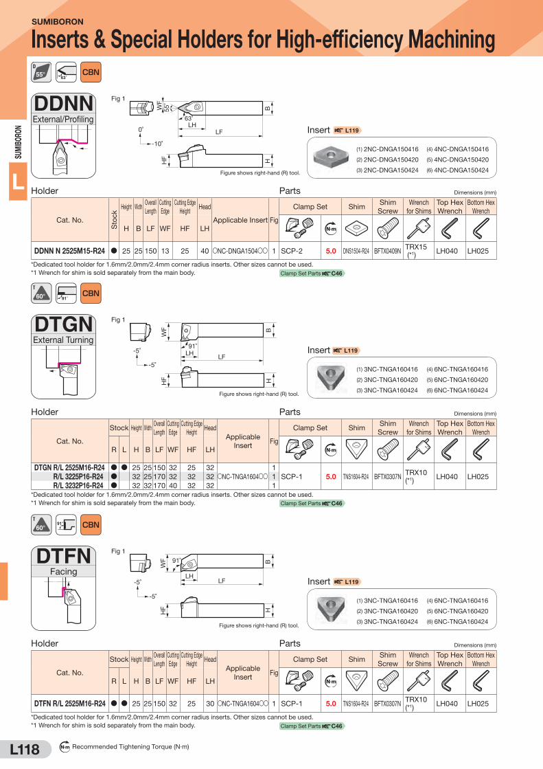
L118
SUM
IBO
RON
L
N m Recommended Tightening Torque (N·m)
SUMIBORON
Inserts & Special Holders for High-efficiency Machining
DDNNExternal/Profiling
Fig 1
WF
HF
BH
63˚
LF
55˚
Figure shows right-hand (R) tool.
LH0˚
-10˚
Holder Parts Dimensions (mm)
Cat. No.
Sto
ck
Height WidthOverall
Length
Cutting
Edge
Cutting Edge
HeightHead
Applicable Insert Fig
Clamp Set ShimShim
Screw
Wrench
for Shims
Top Hex
Wrench
Bottom Hex
Wrench
H B LF WF HF LH N m
DDNN N 2525M15-R24 D 25 25 150 13 25 40 SNC-DNGA1504SS 1 SCP-2 5.0 DNS1504-R24 BFTX0409NTRX15 (*1)
LH040 LH025
*Dedicated tool holder for 1.6mm/2.0mm/2.4mm corner radius inserts. Other sizes cannot be used.
*1 Wrench for shim is sold separately from the main body.
63˚
DTGNExternal Turning
Fig 1
Figure shows right-hand (R) tool.
91˚
LF
HF
WF B
H
LH-5˚
-5˚
Holder Parts Dimensions (mm)
Cat. No.
Stock Height WidthOverall
Length
Cutting
Edge
Cutting Edge
HeightHead
Applicable
InsertFig
Clamp Set ShimShim
Screw
Wrench
for Shims
Top Hex
Wrench
Bottom Hex
Wrench
R L H B LF WF HF LH N m
DTGN R/L 2525M16-R24 D D 25 25 150 32 25 32
SNC-TNGA1604SS1
SCP-1 5.0 TNS1604-R24 BFTX0307NTRX10 (*1)
LH040 LH025DTGN R/L 3225P16-R24 D 32 25 170 32 32 32 1
DTGN R/L 3232P16-R24 D 32 32 170 40 32 32 1
*Dedicated tool holder for 1.6mm/2.0mm/2.4mm corner radius inserts. Other sizes cannot be used.
*1 Wrench for shim is sold separately from the main body.
91˚
DTFNFacing
Fig 1
Figure shows right-hand (R) tool.
LH
WF
HF
BH
91˚
LF-5˚
-5˚
Holder Parts Dimensions (mm)
Cat. No.
Stock Height WidthOverall
Length
Cutting
Edge
Cutting Edge
HeightHead
Applicable
InsertFig
Clamp Set ShimShim
Screw
Wrench
for Shims
Top Hex
Wrench
Bottom Hex
Wrench
R L H B LF WF HF LH N m
DTFN R/L 2525M16-R24 D D 25 25 150 32 25 30 SNC-TNGA1604SS 1 SCP-1 5.0 TNS1604-R24 BFTX0307NTRX10 (*1)
LH040 LH025
*Dedicated tool holder for 1.6mm/2.0mm/2.4mm corner radius inserts. Other sizes cannot be used.
*1 Wrench for shim is sold separately from the main body.
91°
Insert
(1) 2NC-DNGA150416
(2) 2NC-DNGA150420
(3) 2NC-DNGA150424
(4) 4NC-DNGA150416
(5) 4NC-DNGA150420
(6) 4NC-DNGA150424
L119
L119
L119
Insert
(1) 3NC-TNGA160416
(2) 3NC-TNGA160420
(3) 3NC-TNGA160424
(4) 6NC-TNGA160416
(5) 6NC-TNGA160420
(6) 6NC-TNGA160424
Insert
(1) 3NC-TNGA160416
(2) 3NC-TNGA160420
(3) 3NC-TNGA160424
(4) 6NC-TNGA160416
(5) 6NC-TNGA160420
(6) 6NC-TNGA160424
Clamp Set Parts C46
Clamp Set Parts C46
Clamp Set Parts C46

L119
SUM
IBORO
N
L
S mark: Stock or planned stock (please confirm stock availability)
Single-Sided Insert Type ( SUMIBORON) Dimensions (mm)
Appearance Cat. No.
No. of
Cutting
Edges
BN
C2
11
5
BN
C2
12
5
BN
C2
01
0
BN
C2
02
0
BN
C1
60
BN
C2
00
BN
C3
00
Corner
Radius
CBN
Cutting
Edge
Length
Inscribed
CircleThickness Hole Dia.
2NC-CNGA 120416 2 D D D D D 1.6 3.3 12.7 4.76 5.16
2NC-CNGA 120420 2 D D D D D 2.0 3.2 12.7 4.76 5.16
2NC-CNGA 120424 2 D D D D D 2.4 3.1 12.7 4.76 5.16
2NC-DNGA 150416 2 D D D D D 1.6 3.4 12.7 4.76 5.16
2NC-DNGA 150420 2 D D D D D 2.0 3.0 12.7 4.76 5.16
2NC-DNGA 150424 2 D D D D D 2.4 2.7 12.7 4.76 5.16
3NC-TNGA 160416 3 D D D D D 1.6 3.3 9.525 4.76 3.81
3NC-TNGA 160420 3 D D D D D 2.0 3.0 9.525 4.76 3.81
3NC-TNGA 160424 3 D D D D D 2.4 2.7 9.525 4.76 3.81
Double-Sided Insert Type ( SUMIBORON) Dimensions (mm)
Appearance Cat. No.
No. of
Cutting
Edges
BN
C2
11
5
BN
C2
12
5
BN
C2
01
0
BN
C2
02
0
BN
C1
60
BN
C2
00
BN
C3
00
Corner
Radius
CBN
Cutting
Edge
Length
Inscribed
CircleThickness Hole Dia.
4NC-CNGA 120416 4 S S D D D D D 1.6 3.3 12.7 4.76 5.16
4NC-CNGA 120420 4 S S D D D D D 2.0 3.2 12.7 4.76 5.16
4NC-CNGA 120424 4 S S D D D D D 2.4 3.1 12.7 4.76 5.16
4NC-DNGA 150416 4 S S D D D D D 1.6 3.4 12.7 4.76 5.16
4NC-DNGA 150420 4 S S D D D D D 2.0 3.0 12.7 4.76 5.16
4NC-DNGA 150424 4 S S D D D D D 2.4 2.7 12.7 4.76 5.16
6NC-TNGA 160416 6 S S D D D D D 1.6 3.3 9.525 4.76 3.81
6NC-TNGA 160420 6 S S D D D D D 2.0 3.0 9.525 4.76 3.81
6NC-TNGA 160424 6 S S D D D D D 2.4 2.7 9.525 4.76 3.81
SUMIBORON
Inserts & Special Holders for High-efficiency Machining
Application Examples (For Automotive Components)
Corner radius of 2.4mm achieves 2x greater tool life (compared to corner radius of 0.8mm)
Competitor's CBN
No. of Workpieces (pcs.) No. of Workpieces (pcs.)
Competitor's CBN
Corner radius of 1.6mm achieves 1.5x greater tool life (compared to corner radius of 0.8mm)
[R0.8] vc = 120m/min, f = 0.20mm/rev, ap = 0.2mm
Work Material : Carburised Steel (60HRC)
Cutting Conditions : [R2.4] vc = 120m/min, f = 0.35mm/rev, ap = 0.2mm
Work Material : Carburised Steel (60HRC)
Cutting Conditions : vc = 100m/min, f = 0.15mm/rev, ap = 0.1mm
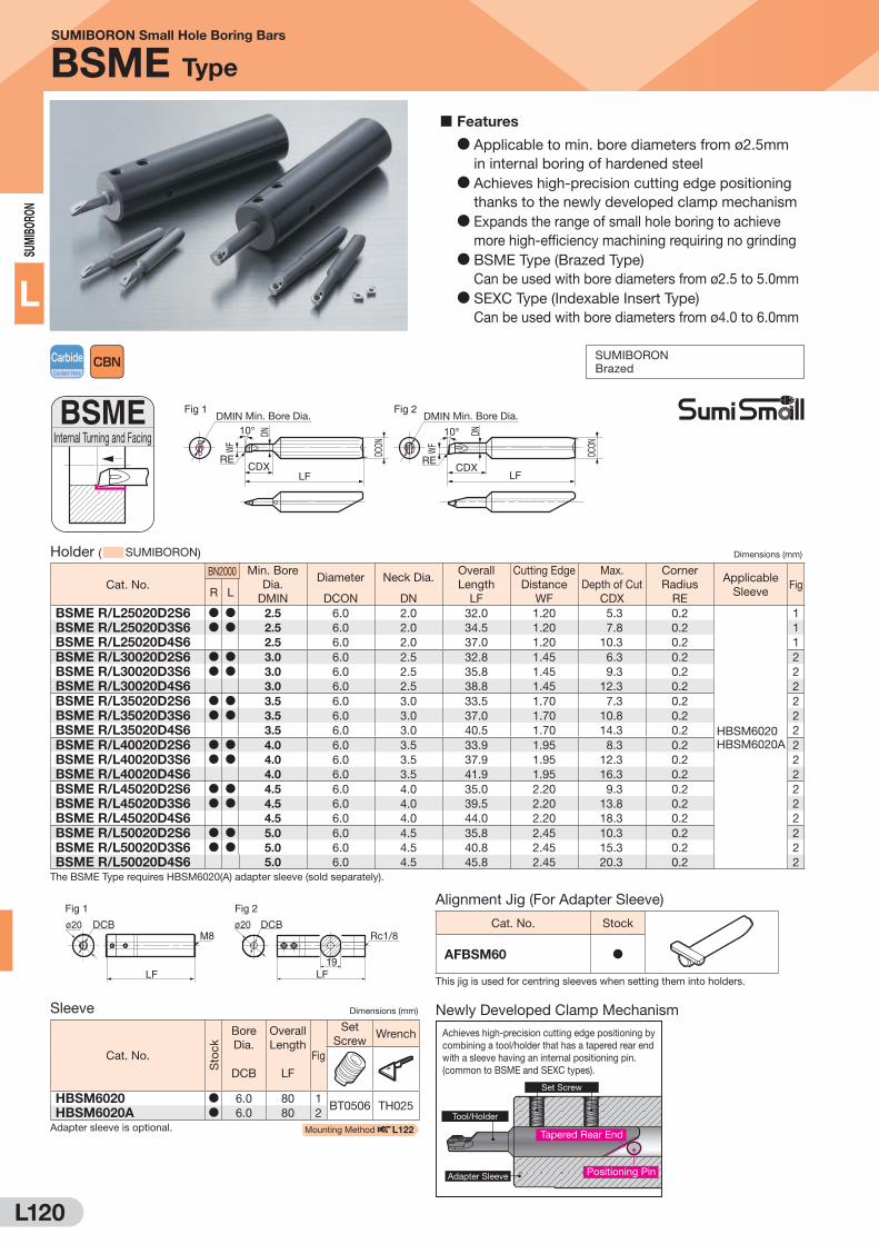
L120
SUM
IBO
RON
L
SUMIBORON Small Hole Boring Bars
BSME Type
Holder ( SUMIBORON) Dimensions (mm)
Cat. No.
BN2000 Min. Bore
Dia.Diameter Neck Dia.
Overall
Length
Cutting Edge
Distance
Max.
Depth of Cut
Corner
RadiusApplicable
SleeveFig
R LDMIN DCON DN LF WF CDX RE
BSME R/L25020D2S6 D D 2.5 6.0 2.0 32.0 1.20 5.3 0.2
HBSM6020
HBSM6020A
1
BSME R/L25020D3S6 D D 2.5 6.0 2.0 34.5 1.20 7.8 0.2 1
BSME R/L25020D4S6 2.5 6.0 2.0 37.0 1.20 10.3 0.2 1
BSME R/L30020D2S6 D D 3.0 6.0 2.5 32.8 1.45 6.3 0.2 2
BSME R/L30020D3S6 D D 3.0 6.0 2.5 35.8 1.45 9.3 0.2 2
BSME R/L30020D4S6 3.0 6.0 2.5 38.8 1.45 12.3 0.2 2
BSME R/L35020D2S6 D D 3.5 6.0 3.0 33.5 1.70 7.3 0.2 2
BSME R/L35020D3S6 D D 3.5 6.0 3.0 37.0 1.70 10.8 0.2 2
BSME R/L35020D4S6 3.5 6.0 3.0 40.5 1.70 14.3 0.2 2
BSME R/L40020D2S6 D D 4.0 6.0 3.5 33.9 1.95 8.3 0.2 2
BSME R/L40020D3S6 D D 4.0 6.0 3.5 37.9 1.95 12.3 0.2 2
BSME R/L40020D4S6 4.0 6.0 3.5 41.9 1.95 16.3 0.2 2
BSME R/L45020D2S6 D D 4.5 6.0 4.0 35.0 2.20 9.3 0.2 2
BSME R/L45020D3S6 D D 4.5 6.0 4.0 39.5 2.20 13.8 0.2 2
BSME R/L45020D4S6 4.5 6.0 4.0 44.0 2.20 18.3 0.2 2
BSME R/L50020D2S6 D D 5.0 6.0 4.5 35.8 2.45 10.3 0.2 2
BSME R/L50020D3S6 D D 5.0 6.0 4.5 40.8 2.45 15.3 0.2 2
BSME R/L50020D4S6 5.0 6.0 4.5 45.8 2.45 20.3 0.2 2
The BSME Type requires HBSM6020(A) adapter sleeve (sold separately).
ø20 DCB
LF
M8
LF
DCBø20
19
Rc1/8
Fig 1 Fig 2
Sleeve Dimensions (mm)
Cat. No.
Sto
ck
Bore
Dia.
Overall
LengthFig
Set
ScrewWrench
DCB LF
HBSM6020 D 6.0 80 1BT0506 TH025
HBSM6020A D 6.0 80 2
Adapter sleeve is optional.
Alignment Jig (For Adapter Sleeve)
Cat. No. Stock
AFBSM60 D
This jig is used for centring sleeves when setting them into holders.
BSMEInternal Turning and Facing
Fig 1 Fig 2 DMIN Min. Bore Dia.
10°
RECDX
LF
WF
DCON
DN
DMIN Min. Bore Dia.
CDXLF
RE
WF
DCON
10° DN
CarbideCoolant Hole
SUMIBORON
Brazed
Achieves high-precision cutting edge positioning by combining a tool/holder that has a tapered rear end with a sleeve having an internal positioning pin.(common to BSME and SEXC types).
Set Screw
Tool/Holder
Positioning Pin
Tapered Rear End
Adapter Sleeve
Newly Developed Clamp Mechanism
Features
D Applicable to min. bore diameters from ø2.5mm
in internal boring of hardened steel
D Achieves high-precision cutting edge positioning
thanks to the newly developed clamp mechanism
D Expands the range of small hole boring to achieve
more high-efficiency machining requiring no grinding
D BSME Type (Brazed Type)
Can be used with bore diameters from ø2.5 to 5.0mm
D SEXC Type (Indexable Insert Type)
Can be used with bore diameters from ø4.0 to 6.0mm
Mounting Method L122

L121
SUM
IBORO
N
L
SUMIBORON Small Hole Boring Bars
SEXC Type
Insert ( SUMIBORON) Dimensions (mm)
Cat. No.
BN
20
00
BN
70
00
Corner
Radius
RE
Fig
Fig 1
75°
ø3.31RE
7°
1.152NU-ECXA 030X02LE D 0.2 1
2NU-ECXA 030X02LF D D 0.2 1
Part Number Suffix: LE: Honing, LF: Sharp EdgeSleeve Dimensions (mm)
Cat. No.
Sto
ck Bore
Dia.
DCB
Overall
Length
LF
Fig
Set
ScrewWrench
HBSM6020 D 6.0 80 1BT0506 TH025
HBSM6020A D 6.0 80 2
Sleeve is optional.
SEXCInternal Turning and Facing
Fig 1
DMIN Min. Bore Dia.10°
WF
DCON
CDXLF
GAMF
DN
Holder Parts Dimensions (mm)
Cat. No.
Stock Min.
Bore Dia.
DMIN
Diameter
DCON
Neck Dia.
DN
Overall
Length
LF
Cutting Edge
Distance
WF
Boring
Depth
CDX
Rake
Angle
GAMF
Applicable
SleeveFig
Bolt Wrench
R L N m
E06D2-SEXC R/L03-04P D D 4.0 6.0 3.75 33.75 1.95 8 -13°
HBSM6020
HBSM6020A
1MIB1.6-2 0.2
SDBSM
E06D3-SEXC R/L03-04P D D 4.0 6.0 3.75 37.75 1.95 12 -13° 1
E06D2-SEXC R/L03-05P D D 5.0 6.0 4.75 35.25 2.45 10 -12° 1MIB1.6-2.5 0.2
E06D3-SEXC R/L03-05P D D 5.0 6.0 4.75 40.25 2.45 15 -12° 1
E06D2-SEXC R/L03-06P D D 6.0 6.0 5.75 36.75 2.95 12 -11° 1MIB1.6-3 0.2
E06D3-SEXC R/L03-06P D D 6.0 6.0 5.75 42.75 2.95 18 -11° 1
The SEXC Type requires HBSM6020(A) adapter sleeve (sold separately).
CarbideCoolant Hole
SUMIBORON
Screw-on
2.0 3.0 4.0 5.0 6.0
Max. Bore Diameter (mm)
Dril
ling
Pre
cisi
on
Good
SEXC Type
Indexable Type
BSME Type
Brazed Type
SEXC
Work Material: Hardened Alloy Steel Valve Component (Automotive Component)
Tool: BSME R50020D2S6 Grade: BN2000
Work Material: Bearing Steel Small Automotive Component (60HRC)
Holder: E06D2-SEXC R/L03-04P Insert: 2NU-ECXA 030X02LF (BN2000)
The BSME type provides stable machining and a tool life that is
over 2 times longer than our competitors' CBN tools.
Competitor's CBN
Tool
No. of Workpieces (pcs.)
Hardened Alloy Steel Valve Components
The SEXC type provides drastically reduced tool costs and a tool
life that is 1.5 times longer than our competitors' brazed CBN tools.
Bearing Steel: Small Automotive Components
0 500 1,000 1,500 2,000
1,700 pieces
600 pieces
Indexable Insert Type
SEXC Type
Brazed Type
BSME Type
Competitor's Brazed
CBN Tool
No. of Workpieces (pcs.)
0 500 1,000 1,500
1,500 pieces
1,000 pieces
Cutting Conditions: vc = 118m/min (7,500min-1), f = 0.02mm/rev, ap = 0.10mm Dry Cutting Conditions: vc = 50m/min (4,000min-1), f = 0.02mm/rev, ap = 0.02mm Wet
BSME
ø5.
0
ø4.
0
Application Range
Application Examples
ø20 DCB
LF
M8
LF
DCBø20
19
Rc1/8
Fig 1 Fig 2
N m Recommended Tightening Torque (N·m)
Recommended Cutting Conditions
Spindle Speed n Above 2,000 min-1
May cause chattering or chipping
at the cutting edge in low-speed
machining.
Depth of Cut ap 0.01 to 0.15mm
Excessive depth of cut causes deformation
of the tool, which consequently leads to
deterioration of dimensional tolerance.
Feed Rate f 0.01 to 0.10mm/rev Q
Alignment Jig (For Adapter Sleeve)
Cat. No. Stock
AFBSM60 D
This jig is used for centring sleeves when setting them into holders. Mounting Method L122
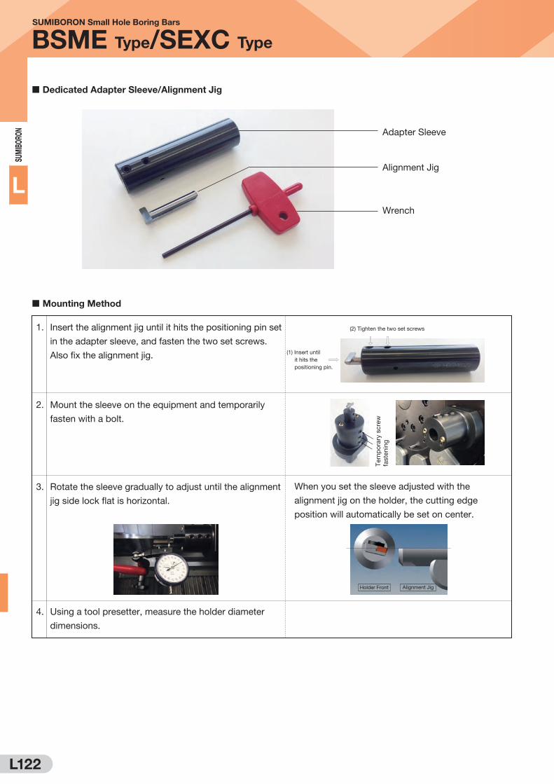
L122
SUM
IBO
RON
L
SUMIBORON Small Hole Boring Bars
BSME Type/SEXC Type
Dedicated Adapter Sleeve/Alignment Jig
Mounting Method
Adapter Sleeve
Alignment Jig
Wrench
1. Insert the alignment jig until it hits the positioning pin set
in the adapter sleeve, and fasten the two set screws.
Also fix the alignment jig.
2. Mount the sleeve on the equipment and temporarily
fasten with a bolt.
3. Rotate the sleeve gradually to adjust until the alignment
jig side lock flat is horizontal.
4. Using a tool presetter, measure the holder diameter
dimensions.
When you set the sleeve adjusted with the
alignment jig on the holder, the cutting edge
position will automatically be set on center.
Tem
po
rary
scre
w
faste
nin
g
(2) Tighten the two set screws
(1) Insert until
it hits the
positioning pin.
Holder Front Alignment Jig

L123
M E M O

L124
SUM
IBO
RON
L
N m Recommended Tightening Torque (N·m)
SUMIBORON Small Hole Boring Bars
BNBX Type
Holder ( SUMIBORON) Dimensions (mm)
Cat. No.
BN
20
00
BN
70
00 Min. Bore
Dia.Diameter Height
Overall
Length
Corner
Radius Applicable
SleeveFig
DMIN DCON H LF RE
BNBX 020R D D 2.5 2.0 1.8 40 0.2 HBX 2016 1
BNBX 025R D D 3.0 2.5 2.2 40 0.2 HBX 2516 1
BNBX 030R D D 3.5 3.0 2.7 40 0.2 HBX 3016 1
BNBX 035R D D 4.0 3.5 3.2 40 0.2 HBX 3516 1
BNBX 040R D D 4.5 4.0 3.7 40 0.2 HBX 4016 1
BNBX 045R D D 5.0 4.5 4.2 40 0.2 HBX 4516 1
BNBX 050R D D 5.5 5.0 4.7 60 0.2 HBX 5016 1
BNBX 055R D D 6.0 5.5 5.2 60 0.2 HBX 5516 1
BNBX 060R D D 6.5 6.0 5.7 60 0.2 HBX 6016 1
BNBX 065R D 7.0 6.5 6.2 60 0.2 HBB 6516 1
BNBX 070R D 7.5 7.0 6.7 80 0.2 HBB 716 1
BNBX 075R D 8.0 7.5 7.2 80 0.2 HBB 7516 1
BNBX 080R D 8.5 8.0 7.7 80 0.2 HBB 816 1
BNBX bars can be used with HBB type sleeves, but HBX type sleeves are recommended for
bars below ø6mm.
Recommended Cutting Conditions
Spindle Speed n Above 2,000 min-1Low speeds may cause chattering
and chipping on the cutting edge.
Depth of Cut ap 0.01 to 0.2mm
Excessive depth of cut may cause
larger tool deformation, resulting in
deterioration of bore accuracy.
Feed Rate f 0.01 to 0.1mm/rev Q
Important Notes(1) Make the holder overhang as short as possible. (Maximum L/D = 5)
(2) Even minor workpiece runout may affect tool life.
(3) Select a boring bar with a diameter as close to the bore diameter
as possible.
(4) Although it is difficult to increase the rotational speed in small-
diameter boring applications, higher speeds are recommended
whenever possible to extend tool life.
D Newly developed high rigidity slit-clamping system, excellent
for small hole internal boring.D Enables maximum overhang of L/D = 5D Minimal deformation produces boring with excellent dimensional tolerance.D Minimal chatter produces superior surface finishD Easy bar indexing while clamped
D Series now includes BN2000 for hardened steel and BN7000
for sintered alloy
BNBXInternal Turning and Facing
92˚
Fig 1 Min. Bore Dia. DMIN
3°
RE LFH
DCON
Fig 1
ø16
100
DCB
1515
Fig 1 ø16
15
DCB
100
Sleeve (HBX Type) Dimensions (mm)
Cat. No.
Sto
ck Bore Dia.
DCB
Applicable Tool
HolderFig
HBX 2016 D 2.0 BNBX 020R 1
HBX 2516 D 2.5 BNBX 025R 1
HBX 3016 D 3.0 BNBX 030R 1
HBX 3516 D 3.5 BNBX 035R 1
HBX 4016 D 4.0 BNBX 040R 1
HBX 4516 D 4.5 BNBX 045R 1
HBX 5016 D 5.0 BNBX 050R 1
HBX 5516 D 5.5 BNBX 055R 1
HBX 6016 D 6.0 BNBX 060R 1
Spare Parts (for Adapter Sleeve)
Applicable Sleeve
Screw Set Screw Wrench
N m
BT06035T
BT0404
TRD (For Torx
Holes)
LH (For Hex Socket)
HBX2SSS BFTX0409N 1.5 BT06035T TRD15
HBX3SSS
BFTX0409N 3.0 BT06035T TRD15HBX4SSSHBX5SSSHBX6SSSHBBSSSS Q Q BT0404 LH020
Sleeve (HBB Type) Dimensions (mm)
Cat. No.
Sto
ck Bore Dia.
DCB
Applicable Tool
HolderFig
HBB 6516 D 6.5 BNBX 065R 1
HBB 716 D 7.0 BNBX 070R 1
HBB 7516 D 7.5 BNBX 075R 1
HBB 816 D 8.0 BNBX 080R 1
HBB Type sleeve can also be used with ø2.5 to 6.0mm holders.
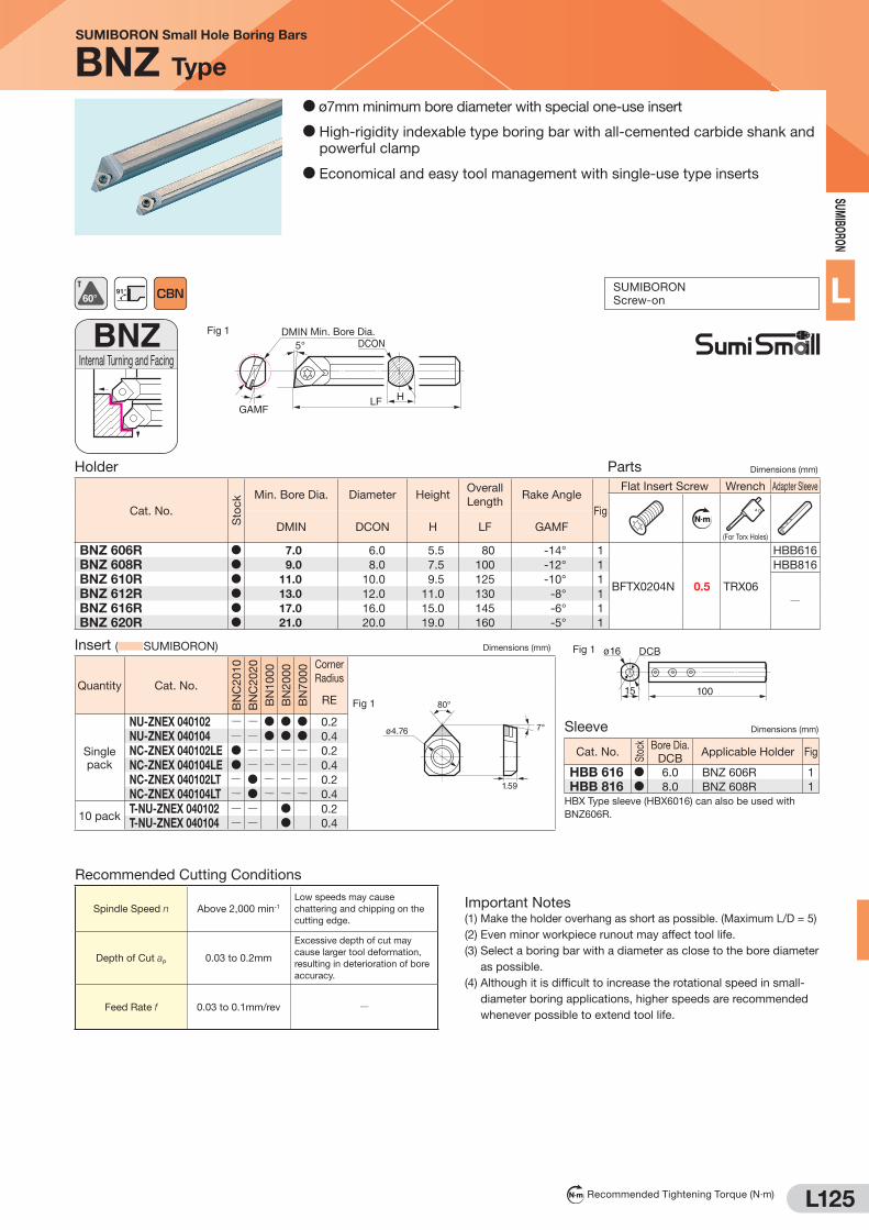
L125
SUM
IBORO
N
L
N m Recommended Tightening Torque (N·m)
SUMIBORON Small Hole Boring Bars
BNZ Type
D ø7mm minimum bore diameter with special one-use insert
D High-rigidity indexable type boring bar with all-cemented carbide shank and
powerful clamp
D Economical and easy tool management with single-use type inserts
Recommended Cutting Conditions
Spindle Speed n Above 2,000 min-1
Low speeds may cause
chattering and chipping on the
cutting edge.
Depth of Cut ap 0.03 to 0.2mm
Excessive depth of cut may
cause larger tool deformation,
resulting in deterioration of bore
accuracy.
Feed Rate f 0.03 to 0.1mm/rev Q
Important Notes(1) Make the holder overhang as short as possible. (Maximum L/D = 5)
(2) Even minor workpiece runout may affect tool life.
(3) Select a boring bar with a diameter as close to the bore diameter
as possible.
(4) Although it is difficult to increase the rotational speed in small-
diameter boring applications, higher speeds are recommended
whenever possible to extend tool life.
Fig 1 ø16
15 100
DCB
BNZInternal Turning and Facing
Fig 1
5° DCON
GAMFLF H
DMIN Min. Bore Dia.
Holder Parts Dimensions (mm)
Cat. No.
Sto
ck Min. Bore Dia. Diameter Height
Overall
LengthRake Angle
Fig
Flat Insert Screw Wrench Adapter Sleeve
N m
(For Torx Holes)DMIN DCON H LF GAMF
BNZ 606R D 7.0 6.0 5.5 80 -14° 1
BFTX0204N 0.5 TRX06
HBB616
BNZ 608R D 9.0 8.0 7.5 100 -12° 1 HBB816
BNZ 610R D 11.0 10.0 9.5 125 -10° 1
QBNZ 612R D 13.0 12.0 11.0 130 -8° 1
BNZ 616R D 17.0 16.0 15.0 145 -6° 1
BNZ 620R D 21.0 20.0 19.0 160 -5° 1
91°
SUMIBORON
Screw-on
Insert ( SUMIBORON) Dimensions (mm)
Quantity Cat. No.
BN
C2
01
0
BN
C2
02
0
BN
10
00
BN
20
00
BN
70
00 Corner
Radius
Fig 1 80°
ø4.76
1.59
7°
RE
Single
pack
NU-ZNEX 040102 Q Q D D D 0.2
NU-ZNEX 040104 Q Q D D D 0.4
NC-ZNEX 040102LE D Q Q Q Q 0.2
NC-ZNEX 040104LE D Q Q Q Q 0.4
NC-ZNEX 040102LT Q D Q Q Q 0.2
NC-ZNEX 040104LT Q D Q Q Q 0.4
10 packT-NU-ZNEX 040102 Q Q D 0.2
T-NU-ZNEX 040104 Q Q D 0.4
Sleeve Dimensions (mm)
Cat. No.
Sto
ck Bore Dia.Applicable Holder Fig
DCB
HBB 616 D 6.0 BNZ 606R 1
HBB 816 D 8.0 BNZ 608R 1
HBX Type sleeve (HBX6016) can also be used with
BNZ606R.

L126
SUM
IBO
RON
L
SUMIBORON Small Hole Boring Bars
BNB Type
D High rigidity full cemented carbide boring bar shankD Minimal deformation produces boring with excellent dimensional tolerance.D Minimal chatter produces superior surface finish.
D Full-top SUMIBORON insert enables 3 cutting edges
D Can be used with SUMIDIA inserts for non-ferrous metal machining
D Now with economical single-corner NF Type SUMIDIA insert
Cutting Performance
30
20
10
0 20 40 60 80 100 120
BNB508R
BNB512R
BNB516R
BNB520RDD
D
DD
D
DCON
Tool Overhang L (mm)
Steel Shank
Carbide Shank
Stable Cutting Range
Region where chatter occurs
Work Material : SKD61 (60HRC)
Insert Cat. No. : TBGN060104B
Cutting Conditions : vc=100m/min, f =0.1mm/rev, ap=0.2mm
Ho
lder
Shank D
iam
ete
r D
CO
N (m
m)
L
Tool Overhang L (mm)
L
30
20
10
0 20 40 60 80 100 120 140
BNB512R
BNB516R
BNB520R
BNB525R
D
DD
D
DCON
D
D
Interrupted (SCM415)
Continuous (SKD61)
Stable Cutting Range
Region where chatter occurs
Work Material : SCM415 (61HRC) Internal Diameter ø45 (6U Groove)
Insert Cat. No. : TBGN060104B
Cutting Conditions : vc=100m/min, f =0.1mm/rev, ap=0.2mm
Ho
lder
Shank D
iam
ete
r D
CO
N (m
m)
BNBInternal Turning and Facing
Fig 1 2°
DMIN Min. Bore Dia.
GAMF LFH
DCON
Figure shows right-hand (R) tool.
Holder Parts Dimensions (mm)
Cat. No.
Sto
ck Min. Bore Dia. Diameter Height
Overall
LengthRake Angle
Fig
Clamp Plate Bolt Nut Wrench
(For Hex Socket)DMIN DCON H LF GAMF
BNB 508R D 10.0 8.0 7.0 140 -9° 1
BNBC
BH0306 BNBW-2
TH020
BNB 510R D 12.0 10.0 9.0 140 -8° 1
FBUP3-A0-9 BNBW-4BNB 512R D 14.0 12.0 11.0 160 -6° 1
BNB 516R D 18.0 16.0 14.0 180 -5° 1
BNB 520R D 22.0 20.0 18.0 180 -4° 1 BH0310 BNBW-7
92˚
PCD SUMIBORON
Clamp-on
Insert ( SUMIBORON, SUMIDIA) Dimensions (mm)
Cat. No.
SUMIBORON SUMIDIA
Corner Radius
Fig 1
ø3.97
60°1.59
5°
5°
BN
X1
0
BN
X2
0
BN
2000
BN
35
0
BN
50
0
BN
7000
DA
15
0
DA
10
00
RE
TBGN 060102B D D D D 0.2
TBGN 060104B D D D D D D D D 0.4
TBGN 060108B D D D D D 0.8
TBGN 060102-BSTN*1 Q D Q Q Q Q Q Q 0.2
TBGN 060104-BSTN*1 Q D Q Q Q Q Q Q 0.4
TBGN 060108-BSTN*1 Q D Q Q Q Q Q Q 0.8
NF-TBGN 060102*2 Q Q Q Q Q Q Q D 0.2
NF-TBGN 060104*2 Q Q Q Q Q Q Q D 0.4
*1 TBGN SSSSSS-BSTN is only available in BNX20 grade and has a smaller negative land angle. (BSTN: -15°, B: -25°. However, the negative land angle is
uniquely configured for each grade.)
*2 NF-TBGN is a single corner insert. (This is not a Full-Top insert)

L127
SUM
IBORO
N
LExternal/ProfilingTRGT Fig 1
ICH
F
BH
LF
45°LH
Figure shows right-hand (R) tool.
Holder Dimensions (mm)
Cat. No.Stock Inscribed Circle
IC
Height
H
Width
B
Overall Length
LF
Cutting Edge Height
HF
Head
LH
Applicable
InsertFig
R L
TRGT R/L2020K05 D 5 20 20 125 20 16 RTGN 0508M0 1
TRGT R/L2020K06 D 6 20 20 125 20 16 RTGN 0608M0 1
TRGT R/L2525M07 7 25 25 150 25 20 RTGN 0711M0 1
TRGT R/L2525M08 D 8 25 25 150 25 20 RTGN 0811M0 1
TRGT R/L3225P09D 9 32 25 170 32 25 RTGN 0914M0 1
D 10 32 25 170 32 25 RTGN 1014M0 1
TRGT R/L3225P12 12 32 25 170 32 25 RTGN 1214M0 1
Inserts are not embedded into tool holders.
Insert ( SUMIBORON) Dimensions (mm)
Cat. No.
BN
20
00
BN
X2
0
BN
70
00
Inscribed Circle
IC
Diameter
D7
Thickness
S
Thickness 2
S4
FigS4
S
IC
D7
12°
6°
Fig 1
RTGN 0508M0 D 5 2.5 7.5 3.5 1
RTGN 0608M0 D 6 3.5 7.5 3.5 1
RTGN 0711M0 D 7 3.5 11.0 5.0 1
RTGN 0811M0 D 8 4.5 11.0 5.0 1
RTGN 0914M0 D 9 5.5 14.0 6.0 1
RTGN 1014M0 D 10 5.5 14.0 6.0 1
RTGN 1214M0 D 12 7.5 14.0 6.0 1
SUMIBORON Small Diameter Round Insert Holders
TRGT Type
D Clamping by cutting force aloneD Secure clamping is achieved by inserting the tapered portion of the insert into the holder.D The lack of protrusions on the insert rake face allows smooth chip evacuation.
D Round insert enables various machining operationsSmall round insert with stable clamping can be applied to various machining operations.
Insert Mounting Details
D8
D7
a b
IC
H
0 12°-10´
0
0.3-
0.3
Supported Insert Diameter IC H D7 D8 a b
5 4.0 2.5 1.9 1.85 3.2
6 4.0 3.5 2.9 2.35 3.7
7 6.0 3.5 2.5 2.75 4.3
8 6.0 4.5 3.5 3.25 4.8
9 7.5 5.5 4.2 4.15 5.9
10 7.5 5.5 4.2 4.15 5.9
12 7.5 7.5 6.2 5.15 6.9
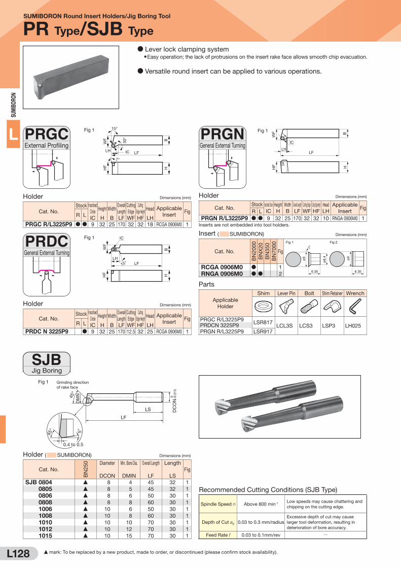
L128
SUM
IBO
RON
LExternal ProfilingPRGC Fig 1
LFIC
7°
HF
WF B
H
30°
15°
LH
Holder Dimensions (mm)
Cat. No.Stock Inscribed
Circle
IC
Height
H
Width
B
Overall
Length
LF
Cutting
Edge
WF
Cutting
Edge Height
HF
Head
LH
Applicable
InsertFig
R L
PRGC R/L3225P9 D D 9 32 25 170 32 32 18 RCGA 0906M0 1
Parts
Applicable
Holder
Shim Lever Pin Bolt Shim Retainer Wrench
PRGC R/L3225P9LSR817
LCL3S LCS3 LSP3 LH025PRDCN 3225P9
PRGN R/L3225P9 LSR917
45°
45°
5°
0.4 to 0.5
LF
DMIN
Grinding direction of rake face
DC
ON
-0.0
150
LS
Fig 1
Holder ( SUMIBORON) Dimensions (mm)
Cat. No.
BN
25
0 Diameter
DCON
Min. Bore Dia.
DMIN
Overall Length
LF
Length
LS
Fig
SJB 0804 F 8 4 45 32 1
SJB 0805 F 8 5 45 32 1
SJB 0806 F 8 6 50 30 1
SJB 0808 F 8 8 60 30 1
SJB 1006 F 10 6 50 30 1
SJB 1008 F 10 8 60 30 1
SJB 1010 F 10 10 70 30 1
SJB 1012 F 10 12 70 30 1
SJB 1015 F 10 15 70 30 1
General External TurningPRDC
Jig BoringSJB
Fig 1
LF
IC
15°
HF
WF
BH
LH
Holder Dimensions (mm)
Cat. No.Stock Inscribed
Circle
IC
Height
H
Width
B
Overall
Length
LF
Cutting
Edge
WF
Cutting
Edge Height
HF
Head
LH
Applicable
InsertFig
R L
PRDC N 3225P9 D 9 32 25 170 12.5 32 25 RCGA 0906M0 1
Insert ( SUMIBORON) Dimensions (mm)
Cat. No.B
N2
00
0
BN
X2
0
BN
35
0
BN
70
00
Fig
Fig 1 Fig 2
ø9 ø9
ø8.
4
6.35 6.35
7°
RCGA 0906M0 D 1
RNGA 0906M0 D D 2
General External TurningPRGN Fig 1
IC
BH
WF
HF
LHLF
Holder Dimensions (mm)
Cat. No.Stock Inscribed Circle
IC
Height
H
Width
B
Overall Length
LF
Cutting Edge
WF
Cutting Edge Height
HF
Head
LH
Applicable
InsertFig
R L
PRGN R/L3225P9 D D 9 32 25 170 32 32 10 RNGA 0906M0 1
Inserts are not embedded into tool holders.
SUMIBORON Round Insert Holders/Jig Boring Tool
PR Type/SJB Type
D Lever lock clamping systemD Easy operation; the lack of protrusions on the insert rake face allows smooth chip evacuation.
D Versatile round insert can be applied to various operations.
Recommended Cutting Conditions (SJB Type)
Spindle Speed n Above 800 min-1Low speeds may cause chattering and
chipping on the cutting edge.
Depth of Cut ap 0.03 to 0.3 mm/radius
Excessive depth of cut may cause
larger tool deformation, resulting in
deterioration of bore accuracy.
Feed Rate f 0.03 to 0.1mm/rev Q
F mark: To be replaced by a new product, made to order, or discontinued (please confirm stock availability).
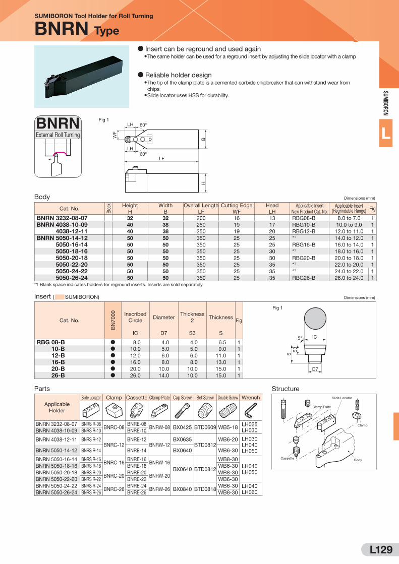
L129
SUM
IBORO
N
LExternal Roll TurningBNRN Fig 1
WF
HB
60°
60°LF
LH
LH
Body Dimensions (mm)
Cat. No.
Sto
ck Height
H
Width
B
Overall Length
LF
Cutting Edge
WF
Head
LH
Applicable Insert
New Product Cat. No.Applicable Insert
(Regrindable Range) Fig
BNRN 3232-08-07 32 32 200 16 13 RBG08-B 8.0 to 7.0 1
BNRN 4038-10-09 40 38 250 19 17 RBG10-B 10.0 to 9.0 1
BNRN 4038-12-11 40 38 250 19 20 RBG12-B 12.0 to 11.0 1
BNRN 5050-14-12 50 50 350 25 25 *1 14.0 to 12.0 1
BNRN 5050-16-14 50 50 350 25 25 RBG16-B 16.0 to 14.0 1
BNRN 5050-18-16 50 50 350 25 30 *1 18.0 to 16.0 1
BNRN 5050-20-18 50 50 350 25 30 RBG20-B 20.0 to 18.0 1
BNRN 5050-22-20 50 50 350 25 35 *1 22.0 to 20.0 1
BNRN 5050-24-22 50 50 350 25 35 *1 24.0 to 22.0 1
BNRN 5050-26-24 50 50 350 25 35 RBG26-B 26.0 to 24.0 1
*1 Blank space indicates holders for reground inserts. Inserts are sold separately.
Insert ( SUMIBORON) Dimensions (mm)
Cat. No.
BN
70
00
Inscribed
Circle
IC
Diameter
D7
Thickness
2
S3
Thickness
S
Fig
Fig 1
IC
D7
5°
SS
3
RBG 08-B D 8.0 4.0 4.0 6.5 1
RBG 10-B D 10.0 5.0 5.0 9.0 1
RBG 12-B D 12.0 6.0 6.0 11.0 1
RBG 16-B D 16.0 8.0 8.0 13.0 1
RBG 20-B D 20.0 10.0 10.0 15.0 1
RBG 26-B D 26.0 14.0 10.0 15.0 1
Parts
Applicable
Holder
Slide Locator Clamp Cassette Clamp Plate Cap Screw Set Screw Double Screw Wrench
BNRN 3232-08-07 BNRS R-08BNRC-08
BNRE-08BNRW-08 BX0425 BTD0609 WB5-18
LH025
LH030BNRN 4038-10-09 BNRS R-10 BNRE-10
BNRN 4038-12-11 BNRS R-12BNRC-12
BNRE-12BNRW-12
BX0635BTD0812
WB6-20 LH030
LH040
LH050BNRN 5050-14-12 BNRS R-14 BNRE-14 BX0640 WB6-30
BNRN 5050-16-14 BNRS R-16BNRC-16
BNRE-16BNRW-16
BX0640 BTD0812
WB8-30
LH040
LH050
BNRN 5050-18-16 BNRS R-18 BNRE-18 WB6-30
BNRN 5050-20-18 BNRS R-20BNRC-20
BNRE-20BNRW-20
WB8-30
BNRN 5050-22-20 BNRS R-22 BNRE-22 WB6-30
BNRN 5050-24-22 BNRS R-24BNRC-26
BNRE-24BNRW-26 BX0840 BTD0818
WB6-30 LH040
LH060BNRN 5050-26-24 BNRS R-26 BNRE-26 WB8-30
SUMIBORON Tool Holder for Roll Turning
BNRN Type
D Insert can be reground and used againD The same holder can be used for a reground insert by adjusting the slide locator with a clamp
D Reliable holder designD The tip of the clamp plate is a cemented carbide chipbreaker that can withstand wear from
chipsD Slide locator uses HSS for durability.
Structure
Clamp Plate
Clamp
BodyCassette
Slide Locator
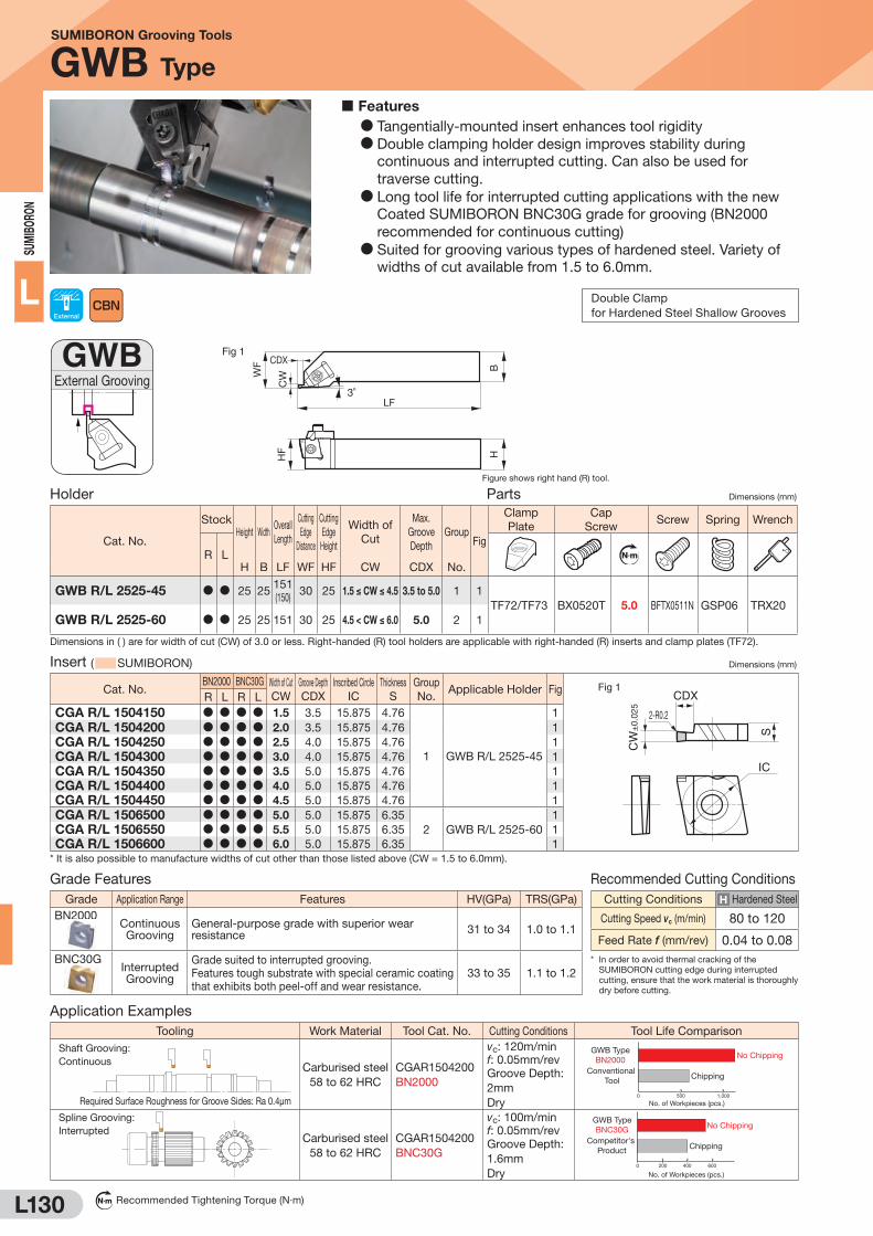
L130
SUM
IBO
RON
L
SUMIBORON Grooving Tools
GWB Type
Insert ( SUMIBORON) Dimensions (mm)
Cat. No.BN2000 BNC30G Width of Cut
CW
Groove Depth
CDX
Inscribed Circle
IC
Thickness
S
Group
No.Applicable Holder Fig Fig 1
CDX
IC
2-R0.2
CW
±0.
025
S
R L R L
CGA R/L 1504150 D D D D 1.5 3.5 15.875 4.76
1 GWB R/L 2525-45
1
CGA R/L 1504200 D D D D 2.0 3.5 15.875 4.76 1
CGA R/L 1504250 D D D D 2.5 4.0 15.875 4.76 1
CGA R/L 1504300 D D D D 3.0 4.0 15.875 4.76 1
CGA R/L 1504350 D D D D 3.5 5.0 15.875 4.76 1
CGA R/L 1504400 D D D D 4.0 5.0 15.875 4.76 1
CGA R/L 1504450 D D D D 4.5 5.0 15.875 4.76 1
CGA R/L 1506500 D D D D 5.0 5.0 15.875 6.35
2 GWB R/L 2525-60
1
CGA R/L 1506550 D D D D 5.5 5.0 15.875 6.35 1
CGA R/L 1506600 D D D D 6.0 5.0 15.875 6.35 1
* It is also possible to manufacture widths of cut other than those listed above (CW = 1.5 to 6.0mm).
External GroovingGWB
Holder Parts Dimensions (mm)
Cat. No.
StockHeight Width
Overall
Length
Cutting
Edge
Distance
Cutting
Edge
Height
Width of
Cut
Max.
Groove
Depth
Group Fig
Clamp
Plate
Cap
ScrewScrew Spring Wrench
R L N m
H B LF WF HF CW CDX No.
GWB R/L 2525-45 D D 25 25151
(150)30 25 1.5 ≤ CW ≤ 4.5 3.5 to 5.0 1 1
TF72/TF73 BX0520T 5.0 BFTX0511N GSP06 TRX20
GWB R/L 2525-60 D D 25 25 151 30 25 4.5 < CW ≤ 6.0 5.0 2 1
Dimensions in ( ) are for width of cut (CW) of 3.0 or less. Right-handed (R) tool holders are applicable with right-handed (R) inserts and clamp plates (TF72).
External Double Clamp
for Hardened Steel Shallow Grooves
Features
D Tangentially-mounted insert enhances tool rigidity
D Double clamping holder design improves stability during
continuous and interrupted cutting. Can also be used for
traverse cutting.
D Long tool life for interrupted cutting applications with the new
Coated SUMIBORON BNC30G grade for grooving (BN2000
recommended for continuous cutting)
D Suited for grooving various types of hardened steel. Variety of
widths of cut available from 1.5 to 6.0mm.
Grade Application Range Features HV(GPa) TRS(GPa)
BN2000Continuous Grooving
General-purpose grade with superior wear resistance
31 to 34 1.0 to 1.1
BNC30GInterrupted Grooving
Grade suited to interrupted grooving.
Features tough substrate with special ceramic coating
that exhibits both peel-off and wear resistance.
33 to 35 1.1 to 1.2
Grade Features
Cutting Conditions H Hardened Steel
Cutting Speed vc (m/min) 80 to 120
Feed Rate f (mm/rev) 0.04 to 0.08
Recommended Cutting Conditions
* In order to avoid thermal cracking of the
SUMIBORON cutting edge during interrupted
cutting, ensure that the work material is thoroughly
dry before cutting.
Tooling Work Material Tool Cat. No. Cutting Conditions Tool Life Comparison
Shaft Grooving:
Continuous
Required Surface Roughness for Groove Sides: Ra 0.4μm
Carburised steel
58 to 62 HRC
CGAR1504200
BN2000
vc: 120m/min
f: 0.05mm/rev
Groove Depth:
2mm
Dry500 1,0000
GWB TypeBN2000
No. of Workpieces (pcs.)
Conventional Tool Chipping
No Chipping
Spline Grooving:
InterruptedCarburised steel
58 to 62 HRC
CGAR1504200
BNC30G
vc: 100m/min
f: 0.05mm/rev
Groove Depth:
1.6mm
Dry400 6000
No Chipping
Chipping
200
GWB TypeBNC30G
Competitor's Product
No. of Workpieces (pcs.)
Application Examples
N m Recommended Tightening Torque (N·m)
Fig 1
BWF
HF
CW
H
CDX
LF3˚
Figure shows right hand (R) tool.
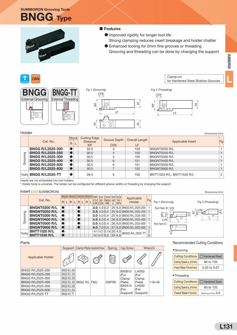
L131
SUM
IBORO
N
L
SUMIBORON Grooving Tools
BNGG Type
Parts
Applicable Holder
Support Clamp Plate Adjustment Screw Spring Cap Screw Wrench
BNGG R/L2525-200 BNGS R/L 200
BNGC R/L FMJ GSP06
BX0615
(For
Clamp
Plate)
BX0414
(For
Support)
LH050
(For
Clamp
Plate)
LH030
(For
Support)
1.8×45
BNGG R/L2525-250 BNGS R/L 250
BNGG R/L2525-300 BNGS R/L 300
BNGG R/L2525-400 BNGS R/L 400
BNGG R/L2525-500 BNGS R/L 500
BNGG R/L2525-600 BNGS R/L 600
BNGG R/L2525-TT BNGS R/L TT
External GroovingBNGG
External ThreadingBNGG-TT Fig 1 (Grooving)
CDX
LF
25
WF
2525
Fig 2 (Threading)
CDX
LF
25WF
Holder Dimensions (mm)
Cat. No.Stock Cutting Edge
Distance
WF
Groove Depth
CDX
Overall Length
LF
Applicable Insert FigR L
Gro
ovin
g
BNGG R/L2525-200 D 30.5 4 150 BNGNT0200 R/L 1
BNGG R/L2525-250 D 30.5 4 150 BNGNT0250 R/L 1
BNGG R/L2525-300 D 30.5 5 150 BNGNT0300 R/L 1
BNGG R/L2525-400 D 30.5 6 151 BNGNT0400 R/L 1
BNGG R/L2525-500 D 30.5 6 151 BNGNT0500 R/L 1
BNGG R/L2525-600 D 30.5 7 152 BNGNT0600 R/L 1
Threading BNGG R/L2525-TT D 28.5 5 150 BNTT1020 R/L, BNTT1530 R/L 2
Inserts are not embedded into tool holders.
* Holder body is universal. The holder can be configured for different groove widths or threading by changing the support.
Insert ( SUMIBORON) Dimensions (mm)
Cat. No.
BN250 BNX20 BN350 BNX25 Width of Cut CW
Groove Depth
CDX
Corner Radius RE
Overall Length L
Cutting Edge Distance
WF3
Applicable
HolderFig
R L R L R L R L
Gro
ovin
g
BNGNT0200 R/L D D 2.0 4.0 0.2 25 6.0 BNGG R/L 2525-200 1
BNGNT0250 R/L D D 2.5 4.0 0.2 25 6.0 BNGG R/L 2525-250 1
BNGNT0300 R/L D D 3.0 5.0 0.4 25 6.0 BNGG R/L 2525-300 1
BNGNT0400 R/L D D 4.0 6.0 0.4 26 6.0 BNGG R/L 2525-400 1
BNGNT0500 R/L D D 5.0 6.0 0.4 26 6.0 BNGG R/L 2525-500 1
BNGNT0600 R/L D D 6.0 7.0 0.4 27 6.0 BNGG R/L 2525-600 1
ThreadingBNTT1020 R/L D Pitch 1.0 to 2.0 0.14 25 4.0
BNGG R/L 2525-TT2
BNTT1530 R/L D Pitch 1.5 to 3.0 0.2 25 4.0 2
External Clamp-on
for Hardened Steel Shallow Grooves
D Improved rigidity for longer tool life
Strong clamping reduces insert breakage and holder chatter
D Enhanced tooling for 2mm fine grooves or threading
Grooving and threading can be done by changing the support
Features
Recommended Cutting Conditions
D Grooving
Cutting Conditions H Hardened Steel
Cutting Speed vc (m/min) 80 to 120
Feed Rate f (mm/rev) 0.03 to 0.07
D Threading
Cutting Conditions H Hardened Steel
Cutting Speed vc (m/min) 80 to 120
Feed Rate f (mm) Maximum Pitch 3.0
Fig 1 (Grooving) Fig 2 (Threading)
L17
RE
6.0
WF360
°
L
5.5
17
6°
2-RE
WF3
CDX
CW±0.
05
Back Taper 30’
Back Taper 30’

L132
SUM
IBO
RON
L
SUMIBORON BN Finish Mill EASY
FMU Type/FMU-E Type
High-speed Finishing for Cast Iron
D High speed finishing cutter for gray cast iron milling that uses removable
cartridges for easy insert runout precision management.
D Utilises BN7000/BN700 grade insert with good wear and fracture resistance.
D Available in shell type and small diameter type with shank.
FeaturesD High-speed machining at vc = up to 2,000m/min.
D Surpasses Rz=3.2 finished surface roughness.
D Safety structure for centrifugal force under high-speed cutting
conditions.
D Runout is less than 10μm: just attach the cartridge.
D Easy runout adjustment using external setting.
D Running cost is reduced because of the economical insert.
Cutting Performance
D Wear Diagram D Estimated Tool Life
0.25
0.20
0.15
0.10
0.05
0 200 400 600 800
Work Material: FC250 240HB (Pearlite)
Cutting Speed: vc = 600 to 2,000m/min Feed Rate: fz = 0.15mm/t
Depth of Cut: ap = 0.5mm Dry Tool Grade: BN700
Fla
nk W
ear
Wid
th V
B (m
m)
Chip Evacuation Rate (cm3)
vc = 600
vc = 800
vc = 1,000
vc = 2,000
vc = 1,500
FF
FF
F
F
F
D
D D D D
DD
1,500
1,000
500
0 500 1,000 1,500 2,000
Work Material: FC250 (Pearlite)
Cutting Speed: vc = 500 to 2,000m/min Feed Rate: fz = 0.2mm/rev
Depth of Cut: ap = 0.3mm Dry Tool Cat. No.: FMU4100R SNEW1203ADTR
Ch
ip E
vacu
atio
n R
ate
(cm
3)
Cutting Speed vc (m/min)
Conventional CBN
BN7000
Milling of ductile cast iron and alloy steel casting does not produce the best results. Dry cutting
is recommended. Wet cutting will result in breakage of cutting edges in the early stages due to
thermal cracking.
Application Range
FC250 to FC300 (200 to 250HB) with pearlite matrix
and gray cast iron (130 to 160HB) with ferrite matrix
[Example] Engine blocks, cylinder heads, etc.
Specifications Recommended Cutting Conditions
D Shell
Shank Type
D Regular Blade
D Low Thrust Blade
ø80 to ø315mm (FMU Type)
ø40 to ø63mm (FMU-E Type)
SNEW1203ADTR/L
SNEW1203ADTR/L-S
D Cutting Speed
D Feed Rate
D Depth of Cut
D Coolant
vc = 800 to 2,000m/min
fz = 0.1 to 0.3mm/t
ap = 0.5mm or less
Dry
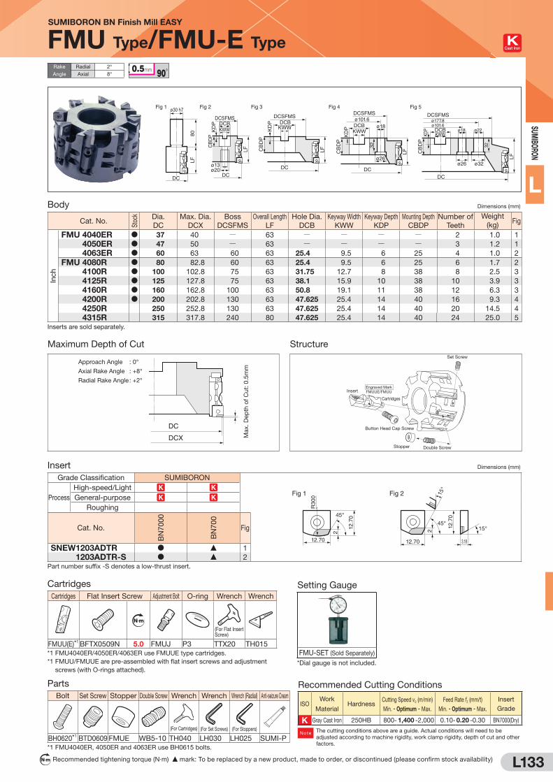
L133
SUM
IBORO
N
L
SUMIBORON BN Finish Mill EASY
FMU Type/FMU-E Type Cast Iron
N m Recommended tightening torque (N·m) F mark: To be replaced by a new product, made to order, or discontinued (please confirm stock availability)
DCSFMS
DC
DCBKWW
LF
DCSFMSø101.6
DC
DCB ø18
ø26
KWW
LF
32
DCSFMS
DC
ø13ø20
DCBKWW
LF
KD
P
DC
LF80
DCSFMS
DC
ø177.8ø101.6
DCB ø18 ø22
ø26 ø32
KWW
LF
32
Fig 2Fig 1 Fig 3 Fig 4 Fig 5ø30 h7
CB
DP
CB
DP
CB
DP
CB
DP
KD
P
KD
P
KDP
Body Dimensions (mm)
Cat. No.
Sto
ck Dia.
DC
Max. Dia.
DCX
Boss
DCSFMS
Overall Length
LF
Hole Dia.
DCB
Keyway Width
KWW
Keyway Depth
KDP
Mounting Depth
CBDP
Number of
Teeth
Weight
(kg)Fig
Inch
FMU 4040ER D 37 40 Q 63 Q Q Q Q 2 1.0 1
FMU 4050ER D 47 50 Q 63 Q Q Q Q 3 1.2 1
FMU 4063ER D 60 63 60 63 25.4 9.5 6 25 4 1.0 2
FMU 4080R D 80 82.8 60 63 25.4 9.5 6 25 6 1.7 2
FMU 4100R D 100 102.8 75 63 31.75 12.7 8 38 8 2.5 3
FMU 4125R D 125 127.8 75 63 38.1 15.9 10 38 10 3.9 3
FMU 4160R D 160 162.8 100 63 50.8 19.1 11 38 12 6.3 3
FMU 4200R D 200 202.8 130 63 47.625 25.4 14 40 16 9.3 4
FMU 4250R 250 252.8 130 63 47.625 25.4 14 40 20 14.5 4
FMU 4315R 315 317.8 240 80 47.625 25.4 14 40 24 25.0 5
Inserts are sold separately.
Insert Dimensions (mm)
Grade Classification SUMIBORON
12.7
0
2 2
12.70
45°
12.7
0
R30
0
12.70
45°15°
3.18
Fig 1 Fig 2 15°
Process
High-speed/Light K KGeneral-purpose K K
Roughing
Cat. No.
BN
70
00
BN
70
0
Fig
SNEW1203ADTR D F 1
1203ADTR-S D F 2
Part number suffix -S denotes a low-thrust insert.
Cartridges
Cartridges Flat Insert Screw Adjustment Bolt O-ring Wrench Wrench
N m
(For Flat Insert Screw)
FMUU(E)*1BFTX0509N 5.0 FMUJ P3 TTX20 TH015
*1 FMU4040ER/4050ER/4063ER use FMUUE type cartridges.
*1 FMUU/FMUUE are pre-assembled with flat insert screws and adjustment
screws (with O-rings attached).
Parts
Bolt Set Screw Stopper Double Screw Wrench Wrench Wrench (Radial) Anti-seizure Cream
(For Cartridges) (For Set Screws) (For Stoppers)
BH0620*1BTD0609 FMUE WB5-10 TH040 LH030 LH025 SUMI-P
*1 FMU4040ER, 4050ER and 4063ER use BH0615 bolts.
Rake
Angle
Radial 2°
Axial 8°
Setting Gauge
FMU-SET (Sold Separately)
*Dial gauge is not included.
Recommended Cutting Conditions
ISOWork
MaterialHardness
Cutting Speed vc (m/min)
Min. - Optimum - Max.
Feed Rate fz (mm/t)
Min. - Optimum - Max.
Insert
Grade
K Gray Cast Iron 250HB 800- 1,400 -2,000 0.10- 0.20 -0.30 BN7000(Dry)
The cutting conditions above are a guide. Actual conditions will need to be
adjusted according to machine rigidity, work clamp rigidity, depth of cut and other
factors.
Note
Maximum Depth of Cut
DC
DCX Max
. Dep
th o
f Cut
: 0.5
mm
Approach Angle : 0°
Axial Rake Angle : +8°
Radial Rake Angle : +2°
Structure
Insert
Cartridges
Button Head Cap Screw
Stopper Double Screw
Set Screw
Engraved MarkFMUUE/FMUU

L134
SUM
IBO
RON
LLF
DC
DCSFMSDCBKWW
ø13ø20
CB
DP
KDP
Fig 1
KDP
DCSFMSDCBKWW
DC
CB
DP
LF
Fig 2
KD
P
DCSFMSø101.6
DCB ø18KWW
DC
ø26
LFCB
DP
32
Fig 3DCSFMS
ø177.8ø101.6
DCB ø18 ø22KWW
DC
ø26 ø32
CB
DP
LF
32
Fig 4
KD
P
Body Dimensions (mm)
Cat. No.Stock Dia.
DC
Max. Dia.
DCX
Boss
DCSFMS
Height
LF
Hole Dia.
DCB
Keyway Width
KWW
Keyway Depth
KDP
Mounting Depth
CBDP
Number
of Teeth
Weight
(kg)Fig
R L
Inch
FM 5080 R/L D 80 82.8 60 50 25.4 9.5 6 25 6 1.6 1
FM 5100 R/L D 100 102.8 75 50 31.75 12.7 8 32 8 2.4 2
FM 5125 R/L D 125 127.8 75 63 38.1 15.9 10 38 10 3.4 2
FM 5160 R/L D 160 162.8 100 63 50.8 19.1 11 38 12 5.6 2
FM 5200 R/L 200 202.8 130 63 47.625 25.4 14 40 16 8.3 3
FM 5250 R/L 250 252.8 130 63 47.625 25.4 14 40 20 14.3 3
FM 5315 R/L 315 317.8 240 80 47.625 25.4 14 40 24 27.8 4
FMF 5125 R/L 125 127.8 75 63 38.1 15.9 10 38 12 3.4 2
FMF 5160 R/L 160 162.8 100 63 50.8 19.1 11 38 16 5.6 2
FMF 5200 R/L 200 202.8 130 63 47.625 25.4 14 40 20 8.3 3
FMF 5250 R/L 250 252.8 130 63 47.625 25.4 14 40 24 14.3 3
FMF 5315 R/L 315 317.8 240 80 47.625 25.4 14 40 28 27.8 4
Inserts are sold separately.
Insert Dimensions (mm)
Grade Classification SUMIBORONFig 1 Fig 2
45°
15°
15°45°
15.875 15.875
15.8
75
15.8
75
R30
0
2 2
Process
High-speed/Light K KGeneral-purpose K K
Roughing
Cat. No.BN7000 BN700
FigR L R L
SNEN 1504ADT R/L D F 1
SNEN 1504ADT R/L-S D F 2
Parts
Applicable
Cutter
Insert Clamp Clamp Adjustment Screw Double Screw Wrench Wrench
FM5080R/LFMW
Q FMJWB7F-20TL TT25
1.8 x 45
FM5100R/LFME Q Q
FM5315R/L
SUMIBORON BN Finish Mill
FM Type/FMF Type
Rake
Angle
Radial 2°
Axial 8°
Cast Iron
High-speed Finishing for Cast Iron
D Specially designed for use with SUMIBORON BN7000/BN700
in high-speed milling of gray cast iron.
Body
DCDCX
Approach Angle : 0°
Axial Rake Angle : +8°
Radial Rake Angle : +2°
a p: 0
.5m
m
Structure
Double Screw
ClampInsert Clamp
Double Screw
Insert
F mark: To be replaced by a new product, made to order, or discontinued (please confirm stock availability).
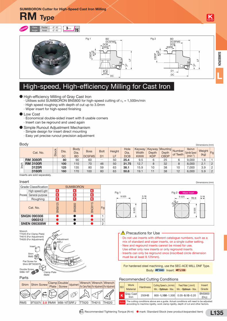
L135
SUM
IBORO
N
L
SUMIBORON Cutter for High-Speed Cast Iron Milling
RM Type Cast Iron
N m Recommended Tightening Torque (N·m) D mark: Standard Stock (new product/expanded item)
Fig 1
75°
LF
KD
P
DCSFMSDCBKWW
ø13ø20
DC
BD
CB
DP
75°
LF
KD
P
DCSFMSDCB
KWW
Fig 2
DC
D1
BD
CB
DP
Body Dimensions (mm)
Cat. No.
Sto
ck
Dia.
DC
Body
Dia.
BD
Boss
DCSFMS
Bolt
D1
Height
LF
Hole
Dia.
DCB
Keyway
Width
KWW
Keyway
Depth
KDP
Mounting
Depth
CBDP
Number
of Teeth
Maximum
Spindle Speed (min-1)
Weight
(kg)Fig
Inch
RM 3080R 80 90 60 Q 50 25.4 9.5 6 25 6 9,000 1.6 1
RM 3100R 100 110 70 46 50 31.75 12.7 8 32 8 8,000 2.1 2
RM 3125R 125 135 80 59 63 38.1 15.9 10 38 10 7,000 3.9 2
RM 3160R 160 170 100 80 63 50.8 19.1 11 38 12 6,000 5.9 2
Inserts are sold separately.
Insert Dimensions (mm)
Grade Classification SUMIBORON
Fig 1 Fig 29.525
9.52
5
3.18 9.5259.
525
3.18R0.8
0.8
0.8
Wiper InsertProcess
High-speed/Light K K KGeneral-purpose K K K
Roughing K K K
Cat. No.
BN
S81
25
BN
S80
0
BN
C81
15
Fig
SNGN 090308 D D D 1
SNGN 090312 D D D 1
SNEN 090308W D D D 2
Parts
Shim Shim ScrewClamp
Plate
Double
ScrewAdjustment
Wrench
(For Clamp Plate)
Wrench
(For Adjustment)
Wrench
(For Adjustment)
N m
RMS BFTX0307N 2.0 RMW WB6-16T SRFJ TTX20 TH015 TH020
Rake
Angle
Radial -6° 45'
Axial -5° 45'
D High-efficiency Milling of Gray Cast Iron · Utilises solid SUMIBORON BNS800 for high-speed cutting of vc = 1,500m/min
· High speed roughing with depth of cut up to 3.0mm
· Wiper insert for high-speed finishing
D Low Cost · Economical double-sided insert with 8 usable corners
· Insert can be reground and used again
D Simple Runout Adjustment Mechanism · Simple design for insert direct mounting
· Easy yet precise runout precision adjustment
WrenchTTX20 (For Clamp Plate)TH015 (For Adjustment)TH020 (For Adjustment)
Insert
Shim RMS
Flat Screw for Shim BFTX0307N
Double Screw WB6-16T Clamp Plate
RMW
Adjustment SRFJ
Recommended Cutting Conditions
ISOWork
MaterialHardness
Cutting Speed vc (m/min)
Min. - Optimum - Max.
Feed Rate fz (mm/t)
Min. - Optimum - Max.
Insert
Grade
KGray Cast
Iron250HB 800- 1,150 -1,500 0.05- 0.13 -0.20
BNS800
(Dry)
The cutting conditions above are a guide. Actual conditions will need to be adjusted
according to machine rigidity, work clamp rigidity, depth of cut and other factors.Note
Precautions for Use
· Do not use inserts with different catalogue numbers, such as a
mix of standard and wiper inserts, on a single cutter setting.
· New and reground inserts cannot be mixed for use.
Use either only new inserts or only reground inserts.
· Inserts can only be reground once (inscribed circle dimension
must be at least 9.125mm).
For hardened steel machining, use the SEC-ACE MILL DNF Type.
Body: H45 Insert: L108
High-speed, High-efficiency Milling for Cast Iron

L136
SUM
IBO
RON
L
Fig 1 Fig 2
DM
M h
7
DC
LF
RE
APMXLH LS
DM
M h
7
DC
LF
RE
LH LSAPMX
Body Dimensions (mm)
Cat. No.
Sto
ck Ballnose Radius
RE
Dia.
DC
Depth
APMX
Neck
LH
Shank
LS
Overall Length
LF
Shank
DMMFig
BES 160S 8.0 16 10.0 50 60 110 20 1
BES 200S 10.0 20 13.0 60 80 140 25 1
BES 250S 12.5 25 15.5 70 80 150 32 1
BES 300S 15.0 30 18.0 80 80 160 32 1
BES 400S 20.0 40 23.0 100 100 200 42 2
BES 500S 25.0 50 28.0 120 100 220 50 2
Inserts are sold separately.
Insert ( SUMIBORON) Dimensions (mm)
Cat. No.
BN
50
0 Ballnose
Radius
RE
Depth
APMX
Length
L
Width
W1
Thickness
S
Applicable
EndmillFig
Fig 1 Fig 2
W1
L
RE
S APMX
W1
L
RE
S APMX
BEST 160S 8.0 10.0 13.0 6.8 3.5BES 160S
1
BEST 160L 8.0 13.0 13.0 6.8 3.5 1
BEST 200S 10.0 13.0 20.0 8.5 4.5BES 200S
1
BEST 200L 10.0 20.0 20.0 8.5 4.5 1
BEST 250S D 12.5 15.5 22.5 10.5 5.0BES 250S
1
BEST 250L D 12.5 22.5 22.5 10.5 5.0 1
BEST 300S D 15.0 18.0 25.0 12.0 6.0BES 300S
1
BEST 300L D 15.0 25.0 25.0 12.0 6.0 1
BEST 400S 20.0 23.0 30.0 16.0 7.5BES 400S
2
BEST 400L 20.0 30.0 30.0 16.0 7.5 2
BEST 500S 25.0 28.0 35.0 20.0 8.0BES 500S
2
BEST 500L 25.0 35.0 35.0 20.0 8.0 2
Parts
Applicable
Endmill
Clamp Plate Double Screw Flat Insert Screw Wrench Wrench
N m
BES 160S Q Q BFTX 0306N 2.0 TRX 10 QBES 200S Q Q BFTX 0407N 3.0 TRX 15 QBES 250S Q Q BFTX 0509N 5.0 TRX 20 QBES 300S Q Q BFTX 0511N 5.0 TRX 20 Q
BES 400S CCM 6BL WB 6-13 BXF 0616 Q Q LH 030LH 040
BES 500S CCM 6BL WB 6-16 BXF 0616 Q Q LH 030LH 040
N m Recommended Tightening Torque (N·m)
SUMIBORON Ballnose Endmills
BES Type Cast Iron
Rake
Angle
Radial 0°
Axial 0° to
D High-speed Endmilling of Cast Iron Die MoldsD Balanced cutting with 2 effective teeth for high-efficiency finishing process
D Unique blade type design with improved central insert fracture resistance for high-precision machining
D Good fracture and wear resistance with SUMIBORON BN500 grade for longer FC/FCD materials tool life
Recommended Cutting Conditions
ISO Cat. No.Cast Iron (FC) Ductile Cast Iron (FCD)
Cutting Speed vc (m/min) Feed Rate f (mm/rev) Depth of Cut ap (mm)Pick Feed
pf (mm) Cutting Speed vc (m/min) Feed Rate f (mm/rev) Depth of Cut ap (mm)Pick Feed
pf (mm)
K
BES 160S 250-500-1000 0.1-0.2-0.4 0.1-0.3-0.4 0.2-0.3-0.5 250-500-1000 0.1-0.2-0.3 0.1-0.2-0.3 0.2-0.3-0.5
BES 200S 250-600-1250 0.2-0.4-0.6 0.1-0.3-0.4 0.3-0.5-0.7 250-600-1250 0.1-0.3-0.5 0.1-0.2-0.4 0.3-0.5-0.7
BES 250S 300-750-1500 0.3-0.5-0.7 0.2-0.4-0.5 0.4-0.6-0.9 300-750-1500 0.2-0.4-0.6 0.2-0.3-0.5 0.4-0.6-0.9
BES 300S 350-800-1500 0.3-0.5-0.7 0.2-0.4-0.5 0.5-0.8-1.1 350-800-1500 0.2-0.4-0.6 0.2-0.3-0.5 0.5-0.8-1.1
BES 400S 500-1000-1500 0.3-0.6-1.0 0.3-0.5-0.7 0.6-1.0-1.4 500-1000-1500 0.2-0.5-0.8 0.3-0.4-0.7 0.6-1.0-1.4
BES 500S 600-1200-1500 0.3-0.6-1.0 0.3-0.5-0.7 0.8-1.3-1.8 600-1200-1500 0.2-0.5-0.8 0.3-0.4-0.7 0.8-1.3-1.8
Important Notes(1) Use a high-rigidity machine and select a high cutting speed with a
low depth of cut.
(2) Use dry cutting conditions.
(Min. - Optimum - Max.)

L137
SUM
IBORO
N
L
Fig 1
RE0.2
0 -0.1
LF
LUAPMX
DMM
h6
DC
SUMIBORON Helical Master
BNES Type Pre-hardened
Steel Hardened
Steel 45 to 55HRC
Hardened
Steel 55 to 60HRC
Hardened
Steel 60 to 65HRC
FluteFlute Helix Angle Side Milling
Cutting Performance
D Wear resistance guaranteeing high-efficiency machining D Finished surface roughness similar to grinding
1 BNES1080
2 Conventional Type (Straight Blade
Type/ø8)
ae A
B
ap
2μm
2μm
0.25mm
2μm
2μm
0.25mm
A Dir. B Dir.
0.25mm 0.25mm
A Dir. B Dir.
D Work Material: SCr15
(Hardened) 55 to 58HRCD Cutting Conditions: vc = 130m/min
vf = 310mm/min
Down-cut Dry
ap=4mm, ae=0.05mm
D Side MillingTooling Cutting ConditionsTooling Cutting Conditions
ae
ap
0.12
0.10
0.08
0.06
0.04
0.02
0 5 10 15 20 25
D
F
F
D DD D
1 BNES1120
2 Competitor A Hardened Steel Coating
D Work Material: SKD11 (Hardened) 60HRCD Cutting Conditions: 1 vc = 100m/min
vf = 186mm/min
2 vc = 40m/min
vf = 186mm/min
Down-cut Dry
ap=8mm, ae=0.05mm
Notch Wear Chattering
Able to Continue
Machining Distance (m)
Fla
nk W
ear
Wid
th (m
m)
D Side Milling
D Special Endmill for Hardened Steel
Special Chip Pocket
Design
SUMIBORON BN350
with Excellent Fracture Resistance
First CBN Square Endmill with
Helical C
utting Edge
Body Dimensions (mm)
Cat. No.
Sto
ck Dia.
DC
Cutting Edge Length
APMX
Neck Length
LU
Overall Length
LF
Shank Dia.
DMMFig
BNES 1060 D 6.0 7.0 11.0 60 10 1
BNES 1080 D 8.0 10.0 14.0 70 10 1
BNES 1100 D 10.0 12.0 17.0 75 12 1
BNES 1120 D 12.0 14.0 20.0 80 12 1
BNES 1140 D 14.0 16.0 21.5 80 16 1
BNES 1160 D 16.0 18.0 24.0 80 16 1
Grade: BN350
High-Hardness Hardened Steel (50 to 57HRC)
Cutting Speed VC 100 to 170m/min
Spindle Speed (min-1)
Feed Rate (mm/min)
Depth of Cut ae (mm)
ø6 to 8 4,000 to 9,000 240 to 540 up to 0.1
ø10 to 12 2,700 to 5,400 180 to 360 up to 0.15
ø14 to 16 2,000 to 3,800 140 to 260 up to 0.2
High-Hardness Hardened Steel (58 to 65HRC)
Cutting Speed VC 80 to 150m/min
Spindle Speed (min-1)
Feed Rate (mm/min)
Depth of Cut ae (mm)
ø6 to 8 3,200 to 8,000 150 to 370 up to 0.08
ø10 to 12 2,100 to 4,800 120 to 370 up to 0.12
ø14 to 16 1,600 to 3,400 110 to 230 up to 0.15
ae
a p
Recommended Cutting Conditions1. Use dry cutting (air blow) conditions.
2. Down cut is recommended.
3. Make overhang as short as possible and use a high-rigidity machine.
Side Milling
DC(mm)
Work Material (Hardness)
Cutting Conditions
DC(mm)
Work Material (Hardness)
Cutting Conditions

L138
SUM
IBO
RON
L
MOLD FINISH MASTER SUMIBORON Radius Endmills
BNBR Type Pre-hardened
Steel Hardened
Steel 45 to 55HRC
Hardened
Steel 55 to 60HRC
Hardened
Steel 60 to 65HRC
FlutesFlutes Corner
Side Milling Face Milling Profiling
Fig 1
LFLU
DM
M h
6
DN
APMX
RE±0.005
DC
0 -0.1
Body Dimensions (mm)
Cat. No.
Sto
ck Dia.
DC
Radius
RE
Cutting Edge Length
APMX
Neck Length
LU
Overall Length
LF
Head Dia.
DN
Shank Dia.
DMMWiper Flat Fig
BNBR 2D020R005-0054 D 0.2 0.05 0.1 0.5 50 0.17 4 No 1
BNBR 2D030R005-0054 D 0.3 0.05 0.15 0.5 50 0.27 4 No 1
BNBR 2D040R005-0054 D 0.4 0.05 0.2 0.5 50 0.37 4 No 1
BNBR 2D050R005-0054 D 0.5 0.05 0.3 0.5 50 0.47 4 No 1
BNBR 2D050R005-0154 D 0.5 0.05 0.3 1.5 50 0.47 4 No 1
BNBR 2D050R005-0254 D 0.5 0.05 0.3 2.5 50 0.47 4 No 1
BNBR 2D050R010-0154 D 0.5 0.10 0.3 1.5 50 0.47 4 No 1
BNBR 2D050R010-0254 D 0.5 0.10 0.3 2.5 50 0.47 4 No 1
BNBR 2D100R005-0304 D 1.0 0.05 0.7 3.0 50 0.97 4 Yes 1
BNBR 2D100R005-0504 D 1.0 0.05 0.7 5.0 50 0.97 4 Yes 1
BNBR 2D100R010-0304 D 1.0 0.10 0.7 3.0 50 0.97 4 Yes 1
BNBR 2D100R010-0504 D 1.0 0.10 0.7 5.0 50 0.97 4 Yes 1
BNBR 2D100R020-0304 D 1.0 0.20 0.7 3.0 50 0.97 4 Yes 1
BNBR 2D100R020-0504 D 1.0 0.20 0.7 5.0 50 0.97 4 Yes 1
BNBR 2D100R030-0304 D 1.0 0.30 0.7 3.0 50 0.97 4 Yes 1
BNBR 2D100R030-0504 D 1.0 0.30 0.7 5.0 50 0.97 4 Yes 1
BNBR 2D150R010-0454 D 1.5 0.10 1.2 4.5 50 1.47 4 Yes 1
BNBR 2D150R010-0754 D 1.5 0.10 1.2 7.5 50 1.47 4 Yes 1
BNBR 2D150R020-0454 D 1.5 0.20 1.2 4.5 50 1.47 4 Yes 1
BNBR 2D150R020-0754 D 1.5 0.20 1.2 7.5 50 1.47 4 Yes 1
BNBR 2D150R030-0454 D 1.5 0.30 1.2 4.5 50 1.47 4 Yes 1
BNBR 2D150R030-0754 D 1.5 0.30 1.2 7.5 50 1.47 4 Yes 1
BNBR 2D200R010-0604 D 2.0 0.10 1.5 6.0 50 1.97 4 Yes 1
BNBR 2D200R020-0604 D 2.0 0.20 1.5 6.0 50 1.97 4 Yes 1
BNBR 2D200R030-0604 D 2.0 0.30 1.5 6.0 50 1.97 4 Yes 1
BNBR 2D200R050-0604 D 2.0 0.50 1.5 6.0 50 1.97 4 Yes 1
Grade: BNX20
Identification Code
BNBR 2 D050 R010 - 015 4Number
of Teeth
Series Code Dia. Corner Radius Neck
Length
Shank
Dia.

L139
SUM
IBORO
N
L
MOLD FINISH MASTER SUMIBORON Radius Endmills
BNBR Type
Recommended Cutting Conditions1. Use a machine with high rigidity for stable cutting.
2. Non-water soluble cutting oil is recommended. Supply as a mist or external coolant.
Take fire prevention precautions to avoid fire hazards caused by sparks igniting during machining or tool breakage.
3. Shorten overhang as much as possible.
4. Adjust cutting conditions as necessary as machine rigidity and other conditions may vary.
5. Depths of cut shown in the table of conditions are maximum depths. Adjust the actual depth of cut to the desired machined
surface roughness.
Work Material STAVAX, NAK80, SKD61 (Up to 52HRC) ELMAX, DC53, SKD11 Modified (Up to 62HRC) YXR3, SKH (Up to 70HRC)
DC
(mm)
RE
(mm)
LU
(mm)
Spindle Speed
(min-1)
Feed Rate
(mm/min)ap (mm) ae (mm)
Spindle Speed
(min-1)
Feed Rate
(mm/min)ap (mm) ae (mm)
Spindle Speed
(min-1)
Feed Rate
(mm/min)ap (mm) ae (mm)
0.2 0.05 0.5 40,000 400 0.005 0.03 40,000 400 0.005 0.03 40,000 250 0.005 0.020.3 0.05 0.5 40,000 500 0.010 0.05 40,000 500 0.010 0.05 40,000 300 0.005 0.030.4 0.05 0.5 40,000 600 0.015 0.1 40,000 600 0.015 0.1 40,000 400 0.01 0.05
0.5
0.05 0.5 40,000
600
0.02 0.15 40,000
600
0.02 0.15 40,000
400 0.01
0.10.05
1.540,000
0.02 0.140,000
0.02 0.135,000
0.050.1 40,000 40,000 35,0000.05
2.540,000
0.01 0.0540,000
0.01 0.0535,000
0.1 40,000 40,000 35,000
1.0
0.05
3.0
35,000
800
0.03 0.3
35,000
800 0.03 0.2
30,000
600 0.01 0.10.1 35,000 35,000 30,0000.2 35,000 35,000 30,0000.3 35,000 35,000 30,0000.05
5.0
35,000
0.02 0.2
35,000
800 0.02 0.1
30,000
600 0.01 0.10.1 35,000 35,000 30,0000.2 35,000 35,000 30,0000.3 35,000 35,000 30,000
1.5
0.14.5
26,000
800
0.03 0.526,000
800 0.03 0.320,000
600 0.02 0.30.2 26,000 26,000 20,0000.3 26,000 26,000 20,0000.1
7.526,000
0.03 0.526,000
800 0.03 0.320,000
600 0.02 0.30.2 26,000 26,000 20,0000.3 26,000 26,000 20,000
2.0
0.1
6.0
20,000
800 0.03 0.7
20,000
800 0.03 0.7
15,000
600 0.03 0.70.2 20,000 20,000 15,0000.3 20,000 20,000 15,0000.5 20,000 20,000 15,000
ae
a p

L140
SUM
IBO
RON
L
MOLD FINISH MASTER SUMIBORON Ballnose Endmills
BNBP Type Pre-hardened
Steel Hardened
Steel 45 to 55HRC
Hardened
Steel 55 to 60HRC
Hardened
Steel 60 to 65HRC
FlutesFlutes Ballnose
Side Milling Face Milling R-Grooving Profiling
Fig 1
DM
M h
6
15˚
RE±0.005
DC
±0
.01
DNAPMX
LFLU
Body Dimensions (mm)
Cat. No.
Sto
ck Radius
RE
Dia.
DC
Cutting Edge Length
APMX
Neck Length
LU
Overall Length
LF
Head Dia.
DN
Shank Dia.
DMMFig
BNBP 2R020-0124 D 0.20 0.4 0.3 1.2 50 0.37 4 1
BNBP 2R020-0126 D 0.20 0.4 0.3 1.2 50 0.37 6 1
BNBP 2R020-0204 D 0.20 0.4 0.3 2.0 50 0.37 4 1
BNBP 2R020-0304 D 0.20 0.4 0.3 3.0 50 0.37 4 1
BNBP 2R020-0404 D 0.20 0.4 0.3 4.0 50 0.37 4 1
BNBP 2R030-0154 D 0.30 0.6 0.4 1.5 50 0.57 4 1
BNBP 2R030-0156 D 0.30 0.6 0.4 1.5 50 0.57 6 1
BNBP 2R030-0304 D 0.30 0.6 0.4 3.0 50 0.57 4 1
BNBP 2R030-0404 D 0.30 0.6 0.4 4.0 50 0.57 4 1
BNBP 2R030-0504 D 0.30 0.6 0.4 5.0 50 0.57 4 1
BNBP 2R030-0604 D 0.30 0.6 0.4 6.0 50 0.57 4 1
BNBP 2R050-0254 D 0.50 1.0 0.6 2.5 50 0.97 4 1
BNBP 2R050-0256 D 0.50 1.0 0.6 2.5 50 0.97 6 1
BNBP 2R050-0304 D 0.50 1.0 0.6 3.0 50 0.97 4 1
BNBP 2R050-0404 D 0.50 1.0 0.6 4.0 50 0.97 4 1
BNBP 2R050-0604 D 0.50 1.0 0.6 6.0 50 0.97 4 1
BNBP 2R050-0804 D 0.50 1.0 0.6 8.0 50 0.97 4 1
BNBP 2R075-0404 D 0.75 1.5 0.9 4.0 50 1.47 4 1
BNBP 2R075-0406 D 0.75 1.5 0.9 4.0 50 1.47 6 1
BNBP 2R100-0554 D 1.00 2.0 1.4 5.5 50 1.97 4 1
BNBP 2R100-0556 D 1.00 2.0 1.4 5.5 50 1.97 6 1
BNBP 2R100-0804 D 1.00 2.0 1.4 8.0 50 1.97 4 1
Grade: BN350
Identification Code
BNBP 2 R030 - 015 4Number
of Teeth
Ballnose
Radius
Neck
Length
Shank
Dia.
Series Code
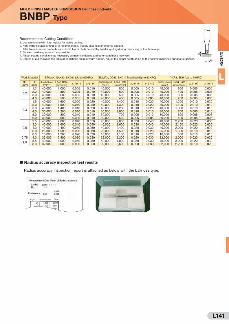
L141
SUM
IBORO
N
L
Radius accuracy inspection report is attached as below with the ballnose type.
Radius accuracy inspection test results
MOLD FINISH MASTER SUMIBORON Ballnose Endmills
BNBP Type
Recommended Cutting Conditions1. Use a machine with high rigidity for stable cutting.
2. Non-water soluble cutting oil is recommended. Supply as a mist or external coolant.
Take fire prevention precautions to avoid fire hazards caused by sparks igniting during machining or tool breakage.
3. Shorten overhang as much as possible.
4. Adjust cutting conditions as necessary as machine rigidity and other conditions may vary.
5. Depths of cut shown in the table of conditions are maximum depths. Adjust the actual depth of cut to the desired machined surface roughness.
Work Material STAVAX, NAK80, SKD61 (Up to 52HRC) ELMAX, DC53, SKD11 Modified (Up to 62HRC) YXR3, SKH (Up to 70HRC)
RE (mm)
LU (mm)
Spindle Speed (min-1)
Feed Rate
(mm/min)ap (mm) pf (mm)
Spindle Speed
(min-1)
Feed Rate
(mm/min)ap (mm) pf (mm)
Spindle Speed
(min-1)
Feed Rate
(mm/min)ap (mm) pf (mm)
0.2
1.2 40,000 1,000 0.005 0.010 40,000 800 0.005 0.010 40,000 600 0.005 0.0052.0 40,000 800 0.005 0.010 40,000 600 0.005 0.010 40,000 400 0.005 0.0053.0 40,000 600 0.005 0.010 40,000 500 0.005 0.010 40,000 300 0.005 0.0054.0 40,000 500 0.005 0.010 40,000 400 0.005 0.005 40,000 200 0.005 0.005
0.3
1.5 40,000 1,600 0.020 0.020 40,000 1,400 0.010 0.020 40,000 1,200 0.010 0.0202.0 40,000 1,500 0.010 0.020 40,000 1,300 0.010 0.020 40,000 1,100 0.010 0.0103.0 40,000 1,400 0.010 0.020 40,000 1,200 0.010 0.020 40,000 1,000 0.010 0.0104.0 30,000 1,200 0.010 0.010 30,000 1,000 0.010 0.010 30,000 700 0.005 0.0105.0 30,000 800 0.010 0.010 30,000 700 0.005 0.010 30,000 600 0.005 0.0056.0 30,000 600 0.005 0.010 30,000 500 0.005 0.005 30,000 400 0.005 0.005
0.5
2.5 40,000 2,800 0.040 0.050 40,000 2,800 0.030 0.040 40,000 2,200 0.020 0.0303.0 40,000 2,600 0.040 0.050 40,000 2,600 0.030 0.040 40,000 2,100 0.020 0.0304.0 40,000 2,400 0.030 0.050 40,000 2,400 0.020 0.030 40,000 2,000 0.020 0.0206.0 25,000 1,500 0.020 0.030 25,000 1,500 0.010 0.020 25,000 1,300 0.010 0.0108.0 16,000 1,200 0.020 0.020 16,000 1,100 0.010 0.020 16,000 850 0.010 0.010
0.75 4.0 32,000 2,400 0.030 0.030 32,000 2,200 0.020 0.030 32,000 2,000 0.020 0.020
1.05.5 40,000 4,000 0.050 0.050 40,000 4,000 0.030 0.030 40,000 3,000 0.020 0.0308.0 32,000 3,000 0.030 0.050 32,000 2,600 0.020 0.030 32,000 2,200 0.010 0.020
a p
pf
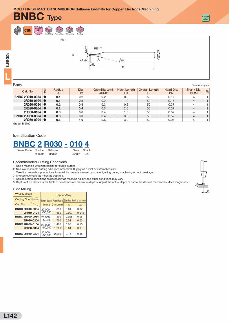
L142
SUM
IBO
RON
L
MOLD FINISH MASTER SUMIBORON Ballnose Endmills for Copper Electrode Machining
BNBC Type
FlutesFlutes Ballnose
Side Milling Face Milling R-Grooving Profiling
Fig 1
LFLU
DM
M h
6
DN
APMX 15˚
RE±0.005
DC
±0.
01Body Dimensions (mm)
Cat. No.
Sto
ck Radius
RE
Dia.
DC
Cutting Edge Length
APMX
Neck Length
LU
Overall Length
LF
Head Dia.
DN
Shank Dia.
DMMFig
BNBC 2R010-0034 D 0.1 0.2 0.2 0.3 50 0.17 4 1
BNBC 2R010-0104 D 0.1 0.2 0.2 1.0 50 0.17 4 1
BNBC 2R020-0054 D 0.2 0.4 0.3 0.5 50 0.37 4 1
BNBC 2R020-0204 D 0.2 0.4 0.3 2.0 50 0.37 4 1
BNBC 2R030-0104 D 0.3 0.6 0.4 1.0 50 0.57 4 1
BNBC 2R030-0304 D 0.3 0.6 0.4 3.0 50 0.57 4 1
BNBC 2R050-0304 D 0.5 1.0 0.6 3.0 50 0.97 4 1
Grade: BN700
Side Milling
Cat. No.
Work Material
Cutting Conditions
Copper Alloy
Spindle Speed
(min-1)
Feed Rate
(mm/min)
Standard depth of cut (mm)
ap pf
BNBC 2R010-0034 20,000 -50,000
350 0.01 0.02
2R010-0104 350 0.007 0.015
BNBC 2R020-0054 20,000 -50,000
800 0.025 0.05
2R020-0204 700 0.02 0.03
BNBC 2R030-0104 20,000 -50,000
1,400 0.05 0.15
2R030-0304 1,200 0.04 0.1
BNBC 2R050-030420,000 -50,000
2,200 0.15 0.35
Recommended Cutting Conditions1. Use a machine with high rigidity for stable cutting.
2. Non-water soluble cutting oil is recommended. Supply as a mist or external coolant.
Take fire prevention precautions to avoid fire hazards caused by sparks igniting during machining or tool breakage.
3. Shorten overhang as much as possible.
4. Adjust cutting conditions as necessary as machine rigidity and other conditions may vary.
5. Depths of cut shown in the table of conditions are maximum depths. Adjust the actual depth of cut to the desired machined surface roughness.
Identification Code
Number
of Teeth
BNBC 2 R030 - 010 4Ballnose
Radius
Neck
Length
Shank
Dia.
Series Code
a p
pf
Copper Alloy

L143
SUM
IBORO
N
LFig 1
±0.02
±0.
03
LF
DC
APMX
DM
M h
6
RE
Body Dimensions (mm)
Cat. No.
Sto
ck Radius
RE
Dia.
DC
Cutting Edge Length
APMX
Overall Length
LF
Shank Dia.
DMMFig
BNBS 2020S D 1.0 2.0 1.5 50 4 1
BNBS 2030S D 1.5 3.0 2.0 60 6 1
BNBS 2040S D 2.0 4.0 3.0 70 6 1
BNBS 2060S D 3.0 6.0 4.5 80 6 1
BNBS 2080S D 4.0 8.0 5.5 90 8 1
BNBS 2100S D 5.0 10.0 6.5 100 10 1
BNBS 2120S D 6.0 12.0 7.5 110 12 1
Grade: BN350
SUMIBORON Ballnose Endmills
BNBS Type
FlutesFlutes Ballnose
Side Milling Face Milling R-Grooving Profiling
Pre-hardened Steel
Hardened Steel
45 to 55HRC
Hardened Steel
55 to 60HRC
Hardened Steel
60 to 65HRC
D Combination of Special Grade and Spiral Cutting Edge Design:
The combination of a special tough SUMIBORON grade with a unique cutting edge design is a
breakthrough for high-efficiency and smooth endmilling of hardened steels.
Cutting Performance
×5,000 ×5,000
BN350250m/min
0.04mm/t
0.3mm
0.3mm
BNBS2100S
Cutting Speed
Feed Rate f
Pitch feed pf
Depth of Cut ap
Tool
Work Material: SKD11 (60HRC Hardness)
Actual Cutting Length : 110m, vB = 0.128mm Continuous Machining Possible
Finished Surface Roughness : Radial Feed Ry1.8μm,
Axial Feed Direction Ry2.2μm
Results
Radial Feed Feed Direction
Recommended Cutting Conditions1. Use a high-rigidity machine and select a high cutting speed with a low feed rate.
2. Use dry cutting conditions.
3. Make overhang as short as possible.
4. If the work material hardness is lower than 50HRC, try the GS MILL Hard Ballnose instead ( I132).
Radius Milling
RE(mm)
Work Material
Cutting Conditions
Hardened Steel
(50 to 57HRC)
Hardened Steel
(58 to 65HRC)
Spindle Speed
(min-1)
Feed Rate
(mm/min)
Spindle Speed
(min-1)
Feed Rate
(mm/min)
1.0 26,000 1,100 22,000 6701.5 18,000 700 15,000 4502.0 13,000 530 11,000 3303.0 8,800 610 7,400 4504.0 6,600 460 5,600 3305.0 5,300 630 4,500 4006.0 4,400 530 3,700 330
Standard Depth
of Cut
ap 0.01DC 0.01DCpf 0.02DC 0.02DC
pf
a p

L144


