
11451 Belcher Road South, Largo, FL 33773 • USA • Tel +1 (727) 447-6140 • Fax +1 (727) 442-5699 www.onicon.com • [email protected] 09-15
System-10 BTU MeterJohnson Controls Metasys® N2 Network Interface Installation Guide
Johnson Controls Metasys® N2
0655-6 / 18322
FLOW AND ENERGY MEASUREMENT

11451 Belcher Road South, Largo, FL 33773 • USA • Tel +1 (727) 447-6140 • Fax +1 (727) 442-5699 • [email protected] BTU Meter Installation and Operation Guide 09/15 - 0655-6 / 18322 Page 2
11451 Belcher Road South, Largo, FL 33773 • USA • Tel +1 (727) 447-6140 • Fax +1 (727) 442-5699 • [email protected] BTU Meter Installation and Operation Guide 09/15 - 0655-6 / 18322 Page 3
TABLE OF CONTENTS
1.0 INTRODUCTION ..................................................................................................5 1.1 PURPOSE OF THIS GUIDE .......................................................................5 1.2 TYPICAL SYSTEM-10 NETWORK INTERFACE MODULE .....................5 1.3 SPECIFICATIONS ......................................................................................5 1.4 NETWORK SIGNAL CONNECTIONS .......................................................6 1.4.1 RS485 ...............................................................................................6 1.4.2 Optional Network Interface with Isolated Digital Pulse Input (Di3) ...................................................7 1.5 RS485 BIASING AND TERMINATION ...................................................10 1.6 NETWORK ADDRESSING .......................................................................10 1.6.1 Changing the Device Address .......................................................102.0 POINT FILE (.ddl) ...............................................................................................12 2.1 .ddl OR POINT INFORMATION .............................................................12 2.1.1 Single Mode Point Information ....................................................12 2.1.2 Dual or Bi-Directional Mode Point Information ..........................13 2.1.3 Supplementary Tables ..................................................................14 2.1.4 Sample .ddl Files ..........................................................................173.0 NETWORK TROUBLESHOOTING TIPS ...........................................................19 3.1 TROUBLESHOOTING .............................................................................19
APPENDIX
A-1 SYSTEM-10 BTU METER COMPUTER BOARD
A-2 SYSTEM-10 BTU METER N2 BOARD
A-3 SYSTEM-10 BTU METER N2 BOARD with Optional Digital Input Pulse (Di3)

11451 Belcher Road South, Largo, FL 33773 • USA • Tel +1 (727) 447-6140 • Fax +1 (727) 442-5699 • [email protected] BTU Meter Installation and Operation Guide 09/15 - 0655-6 / 18322 Page 4
11451 Belcher Road South, Largo, FL 33773 • USA • Tel +1 (727) 447-6140 • Fax +1 (727) 442-5699 • [email protected] BTU Meter Installation and Operation Guide 09/15 - 0655-6 / 18322 Page 5
SECTION 1: INTRODUCTION
1.1 PURPOSE OF THIS GUIDE
The purpose of this guide is to provide installation and commissioning procedures and basic installation and operating instructions for the ONICON System-10-N2 serial interface.
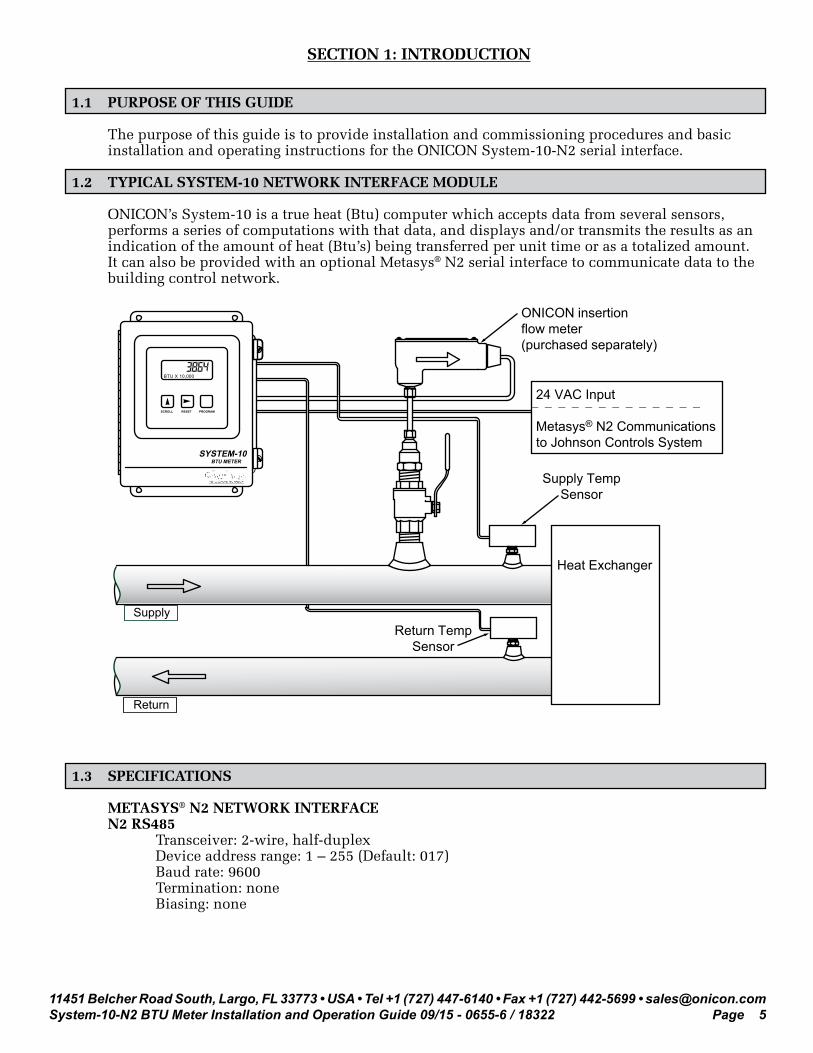
1.2 TYPICAL SYSTEM-10 NETWORK INTERFACE MODULE
ONICON’s System-10 is a true heat (Btu) computer which accepts data from several sensors, performs a series of computations with that data, and displays and/or transmits the results as an indication of the amount of heat (Btu’s) being transferred per unit time or as a totalized amount. It can also be provided with an optional Metasys® N2 serial interface to communicate data to the building control network.
1.3 SPECIFICATIONS
METASYS® N2 NETWORK INTERFACE N2 RS485 Transceiver: 2-wire, half-duplex Device address range: 1 – 255 (Default: 017) Baud rate: 9600 Termination: none Biasing: none
24 VAC Input
Metasys® N2 Communicationsto Johnson Controls System
Heat Exchanger
Return
Supply
SYSTEM-10BTU METER
Return TempSensor
Supply TempSensor
ONICON insertionflow meter(purchased separately)
SCROLL RESET PROGRAM
BTU X 10,000

11451 Belcher Road South, Largo, FL 33773 • USA • Tel +1 (727) 447-6140 • Fax +1 (727) 442-5699 • [email protected] BTU Meter Installation and Operation Guide 09/15 - 0655-6 / 18322 Page 6
1.4 NETWORK SIGNAL CONNECTIONS
1.4.1 RS485 N2 RS485, 2-wire (half-duplex) serial output connections are connected to terminal as shown. Do not exceed 4.4 in-lb (0.5 Nm) of torque when tightening.
CAUTION
Only qualified service personnel should make connections between the System-10-N2 BTU Meter and the user’s external equipment. ONICON assumes no responsibility for damage caused to the external equipment as a result of an improper installation.
!
CAUTION
Incoming and outgoing RS485 cable shield wires should be connected together, but must not be connected to the System-10.
!
N2 (-)
N2 (+)

11451 Belcher Road South, Largo, FL 33773 • USA • Tel +1 (727) 447-6140 • Fax +1 (727) 442-5699 • [email protected] BTU Meter Installation and Operation Guide 09/15 - 0655-6 / 18322 Page 7
1.4.2 Optional Network Interface With Isolated Digital Pulse Input (Di3)
The System-10 BTU Meter can be provided with an auxiliary pulse input for totalizing pulse outputs from external devices such as water or gas meters. Pulses are accumulated in an internal register, and the totalized value is available on the network. This register can be zeroed via the network. The maximum register total is 9,999,999. The register will rollover to zero when this value is exceeded.
If the auxiliary pulse input option was ordered at the same time the Btu meter was ordered, it will arrive fully configured and ready to use. If it was ordered after the Btu meter was delivered and is being installed as a field upgrade, it may be necessary to configure the pulse input. The information required to configure the input is provided below and on the following pages: The input pulse must meet the following criteria: 1. Frequency input range, 50 Hz maximum 2. 10 millisecond minimum pulse duration
Input Pulse Definition: In order to configure the communications card auxiliary pulse input, you must first determine which type of pulse your meter produces. The allowable types of input pulses are described on the following pages. Based on the type of pulse, set the selector switch (S1) on the communications circuit board (Fig. 1) to the correct setting.
Fig. 1 AUX. PULSE INPUT (Di3)

11451 Belcher Road South, Largo, FL 33773 • USA • Tel +1 (727) 447-6140 • Fax +1 (727) 442-5699 • [email protected] BTU Meter Installation and Operation Guide 09/15 - 0655-6 / 18322 Page 8
Powered Pulse:
This type of output refers to a pulse which has an associated voltage with it (see Fig. 2). Set the selector switch, S1 to Pwrd Pulse. The allowable voltage range is 5-24 VDC. The input impedance is set at the factory to be 11 KOHM via the impedance selector jumper (J1, see Fig. 1). A lower impedance, 3 KOHM can be selected if required by the instrument providing the pulse output. Consult the instrument manufacturer or ONICON if you are uncertain as to the proper jumper selection.
Fig. 2
Open Collector (Sourcing):
This type of output refers to an open Collector Switch configured for a sourcing function (see Fig. 3). Set the selector switch, S1 to SRC. The switch must be rated for at least 20mA at 20VDC.
Fig. 3
Di3 In (+)
Di3 In (-)
Di3 In (+)
Di3 In (-)
ONICON BTU Meter
ONICON BTU Meter

11451 Belcher Road South, Largo, FL 33773 • USA • Tel +1 (727) 447-6140 • Fax +1 (727) 442-5699 • [email protected] BTU Meter Installation and Operation Guide 09/15 - 0655-6 / 18322 Page 9
Open Collector Sinking or Dry Contact:
This type of output refers to an open collector switch configured in a current sinking arrangement or a dry contact switch (see Fig. 4 and 5). Set the selector switch, S1 to Sink. In either case, the switch must be rated for at least 20mA at 20 VDC.
Fig. 4
Fig. 5
Di3 In (+)
Di3 In (-)
Di3 In (+)
Di3 In (-)
ONICON BTU Meter
ONICON BTU Meter

11451 Belcher Road South, Largo, FL 33773 • USA • Tel +1 (727) 447-6140 • Fax +1 (727) 442-5699 • [email protected] BTU Meter Installation and Operation Guide 09/15 - 0655-6 / 18322 Page 10
1.5 RS485 BIASING AND TERMINATION
The ONICON System-10-N2 does not provide biasing voltage or termination to the RS485 network. A 120W termination resistor should be used when the meter is installed at the end of the line.
1.6 NETWORK ADDRESSING
Before the System-10 can communicate on the N2 network, the appropriate device address must be programmed into the meter. The N2 network address for ONICON System-10 BTU Meters may be set to any address from 001 to 255. This address is set at the Btu meter. Section 1.6.1 details the procedure for changing this address.
1.6.1 Changing the Device Address
Every ONICON System-10 is individually programmed at the factory with application specific data provided by the customer during the ordering process, and this may include network addressing information. If the device address information was provided, the meter will be programmed with that number. If no address is provided, ONICON Btu meters are programmed with a default address of 017. The address may be changed at the System-10 using the procedure outlined in the table below.
STEP ACTION REACTION COMMENT
0Obtain a device address from the network administrator.
The device address is a three digit number between 001 - 255, excluding zero.
1
With the meter running, open the front panel and locate switch DEV ADD/PROG ENAB. Press DEV ADD/PROG ENAB and then release it.
None
The DEV ADD/PROG ENAB is located on the heat computer board. (See appendix page A-1.)
2 Close the front panel.
3
Press the PROGRAM button. (If you do not press the PROGRAM button, the meter will revert to the RUN mode after 5 minutes.)
The System-10 changes to PROGRAM mode and the DEVICE ID page will appear with the first digit of the address flashing.
The PROGRAM button is on the front panel.

11451 Belcher Road South, Largo, FL 33773 • USA • Tel +1 (727) 447-6140 • Fax +1 (727) 442-5699 • [email protected] BTU Meter Installation and Operation Guide 09/15 - 0655-6 / 18322 Page 11
STEP ACTION REACTION COMMENT
4Successively press the SCROLL button to increment the number to the desired value from 0-9.
The number increments by one each time you press the button.
The SCROLL button is on the front panel.
5 Press the RESET button.The second character blinks.
The RESET button is on the front panel.
6Successively press the SCROLL button to increment the number to the desired value from 0-9.
The number increments by one each time you press the button.
The SCROLL button is on the front panel.
7 Press the RESET button.The third character blinks.
The RESET button is on the front panel
8Successively press the SCROLL button to increment the number to the desired value from 0-9.
The number increments by one each time you press the button.
The SCROLL button is on the front panel.
9Once the correct address is displayed, momentarily press the PROGRAM pushbutton.
The FM LOCN page appears with UNKNWN defaulted as the current location.
The PROGRAM button is on the front panel.
10 Press the SCROLL button.The setting will toggle between UNKNOWN, SUPPLY, and RETURN.
Refer to Section 4.5 of the System-10 Installation and Operation Guide if you with to change settings.
11 Press the PROGRAM button.The FRONT PANEL RESET page appears.
It is not necessary to change anything on this page.
12 Press the PROGRAM button.The SAVE CHANGES page appears.
The new device address must be saved to take effect.
13 Press the SCROLL button.The N changes to Y on the SAVE CHANGES page.
The Y must be selected in order for the new address to take effect.
14 Press the PROGRAM button.The new address is saved and the display reverts to the RUN mode.
15Open the front panel and locate the RESET switch. Press to reset the System-10.
When polled, the System-10 will automatically begin to communicate with the network.
RESET is located along the top of the heat computer board. (See appendix page A-1.)

11451 Belcher Road South, Largo, FL 33773 • USA • Tel +1 (727) 447-6140 • Fax +1 (727) 442-5699 • [email protected] BTU Meter Installation and Operation Guide 09/15 - 0655-6 / 18322 Page 12
SECTION 2.0: POINT FILE (.ddl)
2.1 ddl OR POINT FILE
The System-10 BTU Meter operates in one of three operating modes: single, dual or bi-directional. The dual and bi-directional modes utilize the same .ddl files. The tables below contain point information for each of the operating modes.
The .ddl file contains the information that identifies the device to the N2 supervisory controller. It also specifies the variables that are available to be transmitted to and from the device on the network.
The tables below contains .ddl file information
2.1.1 Single Mode Point Information
In single mode operation, only one register accumulates energy and one register accumulates volume.
NPT1 NPA2 UNITS POINT DESCRIPTION RANGE/VALUE
AI 1 Selectable(See Energy Rate
Table)
Energy Rate 0 - 999,999
AI 2 Selectable(See Volume Rate
Table)
Volume Rate 0 - 999,999
AI 3 Deg F Supply Temperature 0.0 Deg F - 500.0 Deg F
AI 4 Deg F Return Temperature 0.0 Deg F - 500.0 Deg F
BI 1 None Dual Mode Status Indicator- Heating (supply > return)- Cooling (supply < return)
OR- Forward flow- Reverse flow
(Refer to Section 3.3.3 of System-10 manual for flow direction information.)
0 - Heating1 - Cooling
0 - Forward1 - Reverse
ADF 1 Selectable(See Energy Total
Table)
Mode 1 Energy Total 0 – 999,999
ADF 2 Selectable(See Volume Total
Table)
Mode 1 Volume Total 0 – 999,999
ADF 5 User Defined Auxiliary Pulse Input Sum (Di3) 0 – 999,999
BO 1 None Reset (Zero)Energy Total, ADF-1
OVERRIDEBinary Output,Object 1 - ON

11451 Belcher Road South, Largo, FL 33773 • USA • Tel +1 (727) 447-6140 • Fax +1 (727) 442-5699 • [email protected] BTU Meter Installation and Operation Guide 09/15 - 0655-6 / 18322 Page 13
NPT1 NPA2 UNITS POINT DESCRIPTION RANGE/VALUE
BO 2 None Reset (Zero)Volume Total, ADF-2
OVERRIDEBinary Output,Object 2 - ON
BO 5 None Rest (Zero)Auxiliary Pulse Sum (Di3)
OVERRIDEBinary Output,Object 5 - ON
Note 1: Network Point Type Note 2: Network Point Address
2.1.2 Dual or Bi-Directional Mode Point Information
In either dual or bi-directional operation, two registers are available for the accumulation of energy and two are available for the accumulation of volume. Thus, four ADF points are required. Four binary output points are required to zero the four ADF energy and volume accumulation registers.
NPT1 NPA2 UNITS POINT DESCRIPTION RANGE / VALUE
AI 1 Selectable(See Energy Rate Table)
Energy Rate 0 – 999,999
AI 2 Selectable(See Volume Rate Table)
Volume Rate 0 – 999,999
AI 3 Deg F Supply Temperature 0.0 Deg F – 250.0 Deg F
AI 4 Deg F Return Temperature 0.0 Deg F – 250.0 Deg F
BI 1 None Heating – Cooling Indicator 0 – Heating; 1 - Cooling
ADF 1 Selectable(See Energy Total Table)
Mode 1 Energy Total 0 – 999,999
ADF 2 Selectable(See Volume Total Table)
Mode 1 Volume Total 0 – 999,999
ADF 3 Selectable(See Energy Total Table)
Mode 2 Energy Total 0 – 999,999
ADF 4 Selectable(See Volume Total Table)
Mode 2 Volume Total 0 – 999,999
ADF 5 User Defined Auxiliary Pulse Input Sum (Di3)
0 – 999,999
BO 1 None Reset Mode 1 Energy Total OVERRIDEBinary Output, Object 1 - ON
BO 2 None Reset Mode 1 Volume Total OVERRIDEBinary Output,Object 2 - ON
BO 3 None Reset Mode 2 Energy Total OVERRIDEBinary Output,Object 3 - ON

11451 Belcher Road South, Largo, FL 33773 • USA • Tel +1 (727) 447-6140 • Fax +1 (727) 442-5699 • [email protected] BTU Meter Installation and Operation Guide 09/15 - 0655-6 / 18322 Page 14
NPT1 NPA2 UNITS POINT DESCRIPTION RANGE / VALUE
BO 4 None Reset Mode 2 Volume Total OVERRIDEBinary Output,Object 4 - ON
BO 5 None Reset (Zero)Auxiliary Pulse Sum
OVERRIDEBinary Output,Object 5 - ON
Note 1: Network Point Type Note 2: Network Point Address
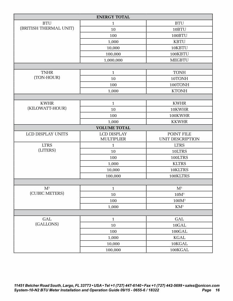
2.1.3 Supplementary Tables
The following tables illustrate the setting of unit descriptions in the .ddl file.
ENERGY RATELCD DISPLAY UNITS LCD DISPLAY MULTIPLIER POINT FILE UNIT
DESCRIPTIONBTU / HR 1 BTU / H
10 10BTU / H100 100BTU / H
1,000 KBTU / H10,000 10KBTU / H
100,000 100KBTU / H1,000,000 MEGBTU / H
TONS 1 TONS10 10TONS
100 100TONS
KW 1 KW10 10KW100 100KW
1,000 KKWVOLUME RATE
LCD DISPLAY UNITS LCD DISPLAY MULTIPLIER
POINT FILE UNIT DESCRIPTION
L / S(LITERS / SECOND)
1 L / S10 10L / S

11451 Belcher Road South, Largo, FL 33773 • USA • Tel +1 (727) 447-6140 • Fax +1 (727) 442-5699 • [email protected] BTU Meter Installation and Operation Guide 09/15 - 0655-6 / 18322 Page 15
L / M(LITERS / MINUTE)
1 L / M10 10L / M100 100L / M
1,000 KL / M10,000 10KL / M
100,000 100KL / M1,000,000 MEGKL / M
L / H(LITERS / HOUR)
1 L / H10 10L / H
100 100L / H1,000 KL / H
10,000 10KL / H100,000 100KL / H
1,000,000 MEGKL /H
M3H(METERS CUBED / HOUR)
1 M3H10 10M3H
GPM(GALLONS / MINUTE)
1 GPM10 10GPM
GPH(GALLONS / HOUR)
1 GPH10 10GPH
100 100GPH1,000 KGPH10,000 10KGPH
100,000 100KGPH1,000,000 MEGGPH
MGD(MILLION GALLONS / DAY)
1 MGD10 10MGC
11451 Belcher Road South, Largo, FL 33773 • USA • Tel +1 (727) 447-6140 • Fax +1 (727) 442-5699 • [email protected] BTU Meter Installation and Operation Guide 09/15 - 0655-6 / 18322 Page 16
ENERGY TOTALBTU
(BRITISH THERMAL UNIT)1 BTU10 10BTU
100 100BTU1,000 KBTU10,000 10KBTU
100,000 100KBTU1,000,000 MEGBTU
TNHR(TON-HOUR)
1 TONH10 10TONH
100 100TONH1,000 KTONH
KWHR(KILOWATT-HOUR)
1 KWHR10 10KWHR100 100KWHR
1,000 KKWHRVOLUME TOTAL
LCD DISPLAY UNITS LCD DISPLAY MULTIPLIER
POINT FILE UNIT DESCRIPTION
LTRS(LITERS)
1 LTRS10 10LTRS100 100LTRS
1,000 KLTRS10,000 10KLTRS100,000 100KLTRS
M3
(CUBIC METERS)1 M3
10 10M3
100 100M3
1,000 KM3
GAL(GALLONS)
1 GAL10 10GAL
100 100GAL1,000 KGAL10,000 10KGAL
100,000 100KGAL

11451 Belcher Road South, Largo, FL 33773 • USA • Tel +1 (727) 447-6140 • Fax +1 (727) 442-5699 • [email protected] BTU Meter Installation and Operation Guide 09/15 - 0655-6 / 18322 Page 17
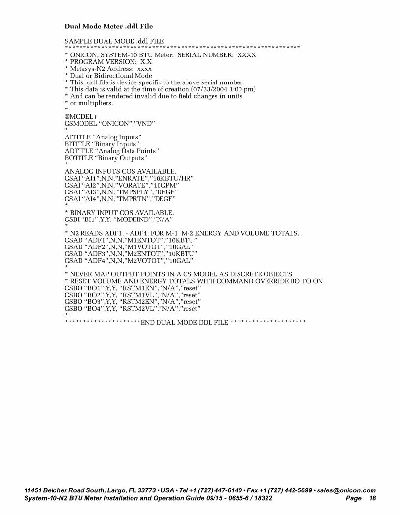
2.1.4 SAMPLE .ddl FILES
Single Mode Meter .ddl File
SAMPLE SINGLE MODE .ddl FILE***************************************************************** * ONICON, SYSTEM-10 BTU Meter: SERIAL NUMBER: XXXX* PROGRAM VERSION: X.X* Metasys-N2 Address: xxxx* Single Mode* This .ddl file is device specific to the above serial number.*.This data is valid at the time of creation (07/23/2004 1:00 pm)* And can be rendered invalid due to field changes in units* or multipliers.*@MODEL+CSMODEL “ONICON”,”VND”*AITITLE “Analog Inputs”BITITLE “Binary Inputs”ADTITLE “Analog Data Points”BOTITLE “Binary Outputs”*ANALOG INPUTS COS AVAILABLE.CSAI “AI1”,N,N,”ENRATE”,”10KBTU/HR”CSAI “AI2”,N,N,”VORATE”,”10GPM”CSAI “AI3”,N,N,”TMPSPLY”,”DEGF”CSAI “AI4”,N,N,”TMPRTN”,”DEGF”** BINARY INPUT COS AVAILABLE.CSBI “BI1”,Y,Y, “MODEIND”,”N/A”** N2 READS ADF1, ADF2 FOR ENERGY AND VOLUME TOTALS.CSAD “ADF1”,N,N,”ENERTOT”,”10KBTU”CSAD “ADF2”,N,N,”VOLMTOT”,”10GAL”CSAD “ADF5”,N,N,”CNTSTOT”,”PLSSUM”** NEVER MAP OUTPUT POINTS IN A CS MODEL AS DISCRETE OBJECTS.* RESET VOLUME AND ENERGY TOTALS WITH COMMAND OVERRIDE BO ONCSBO “BO1”,Y,Y, “RSTENTOT”,”N/A”,”reset”CSBO “BO2”,Y,Y, “RSTVLTOT”,”N/A”,”reset”CSBO “BO5”,Y,Y,”RSTAXTOT”,”N/A”,”reset”****************END SINGLE MODE DDLFILE***************************
11451 Belcher Road South, Largo, FL 33773 • USA • Tel +1 (727) 447-6140 • Fax +1 (727) 442-5699 • [email protected] BTU Meter Installation and Operation Guide 09/15 - 0655-6 / 18322 Page 18
Dual Mode Meter .ddl File
SAMPLE DUAL MODE .ddl FILE***************************************************************** * ONICON, SYSTEM-10 BTU Meter: SERIAL NUMBER: XXXX* PROGRAM VERSION: X.X* Metasys-N2 Address: xxxx* Dual or Bidirectional Mode* This .ddl file is device specific to the above serial number.*.This data is valid at the time of creation (07/23/2004 1:00 pm)* And can be rendered invalid due to field changes in units* or multipliers.*@MODEL+CSMODEL “ONICON”,”VND”*AITITLE “Analog Inputs”BITITLE “Binary Inputs”ADTITLE “Analog Data Points”BOTITLE “Binary Outputs”*ANALOG INPUTS COS AVAILABLE.CSAI “AI1”,N,N,”ENRATE”,”10KBTU/HR”CSAI “AI2”,N,N,”VORATE”,”10GPM”CSAI “AI3”,N,N,”TMPSPLY”,”DEGF”CSAI “AI4”,N,N,”TMPRTN”,”DEGF”** BINARY INPUT COS AVAILABLE.CSBI “BI1”,Y,Y, “MODEIND”,”N/A”** N2 READS ADF1, - ADF4, FOR M-1, M-2 ENERGY AND VOLUME TOTALS.CSAD “ADF1”,N,N,”M1ENTOT”,”10KBTU”CSAD “ADF2”,N,N,”M1VOTOT”,”10GAL”CSAD “ADF3”,N,N,”M2ENTOT”,”10KBTU”CSAD “ADF4”,N,N,”M2VOTOT”,”10GAL”** NEVER MAP OUTPUT POINTS IN A CS MODEL AS DISCRETE OBJECTS.* RESET VOLUME AND ENERGY TOTALS WITH COMMAND OVERRIDE BO TO ONCSBO “BO1”,Y,Y, “RSTM1EN”,”N/A”,”reset”CSBO “BO2”,Y,Y, “RSTM1VL”,”N/A”,”reset”CSBO “BO3”,Y,Y, “RSTM2EN”,”N/A”,”reset”CSBO “BO4”,Y,Y, “RSTM2VL”,”N/A”,”reset”**********************END DUAL MODE DDL FILE *********************

11451 Belcher Road South, Largo, FL 33773 • USA • Tel +1 (727) 447-6140 • Fax +1 (727) 442-5699 • [email protected] BTU Meter Installation and Operation Guide 09/15 - 0655-6 / 18322 Page 19
SECTION 3: NETWORK TROUBLESHOOTING TIPS
3.1 TROUBLESHOOTING
Reported Problem Possible SolutionsDevice will not communicate with the network controller.
• A unique address is required for each device on the network. Duplicate addresses will cause some or all of the devices on the network to quit working. (See section 1.6.1 of this manual for details.)
• The RS485 network cable connections are polarity sensitive and must be connected the same way on every device. (i.e. + to + and - to -). (See section 1.4.1 of this manual for details.)
• Shield drain connections should be daisy chained in the same manner as the signal cables for RS485. The shield drain wire should be left unterminated at the end of the cable and connected to earth only at the supervisory controller. Shield wires must not be connected to the RS485 connector on the System-10.
• The maximum number of devices allowed on a RS485 network segment without a repeater is 32. Adding more than 32 devices to a single segment may reduce the transceiver output voltage to a level that is too low to be distinguished from background noise on the cable.
• RS485 cable impedance should be matched to a termination resistor at the end of the cable. ONICON boards do not have a resistor for termination. A resistor should only be used if the display is the last device on the network cable. (See section 1.5.1 of this manual for details.)

11451 Belcher Road South, Largo, FL 33773 • USA • Tel +1 (727) 447-6140 • Fax +1 (727) 442-5699 • [email protected] BTU Meter Installation and Operation Guide 09/15 - 0655-6 / 18322 Page 20
Reported Problem Possible SolutionsNetwork communications are disrupted when the device is connected.
• The RS485 network cable connections are • polarity sensitive and must be connected • the same way on every device. (i.e. + to • + and - to -). (See section 1.4.1 of this • manual for details.)
• A unique address is required for each device on the network. Duplicate addresses will cause some or all of the devices on the network to quit working. (See section 1.6.1 of this manual for details.)
• Shield drain connections should be daisy • chained in the same manner as the signal cables for RS485. The shield drain wire should be left unterminated at the end of the cable and connected to earth only at the network master controller. Shield wires must not be connected to the RS485 connector on the System-10.

11451 Belcher Road South, Largo, FL 33773 • USA • Tel +1 (727) 447-6140 • Fax +1 (727) 442-5699 • [email protected] BTU Meter Installation and Operation Guide 09/15 - 0655-6 / 18322 Page 21
APPENDIX
A-1 SYSTEM-10 BTU METER COMPUTER BOARD
A-2 SYSTEM-10 BTU METER N2 BOARD
A-3 SYSTEM-10 BTU METER N2 BOARD with Auxiliary Input Pulse

11451 Belcher Road South, Largo, FL 33773 • USA • Tel +1 (727) 447-6140 • Fax +1 (727) 442-5699 • [email protected] BTU Meter Installation and Operation Guide 09/15 - 0655-6 / 18322 Page A-1
SYSTEM-10 BTU METER COMPUTER BOARD
Reset
Temp Test
Prog ModeEnable
Device AddressProgram Enable
Serial Comm
FLOW AND ENERGY MEASUREMENT
11451 Belcher Road South, Largo, FL 33773 • USA • Tel +1 (727) 447-6140 • Fax +1 (727) 442-5699 • [email protected] BTU Meter Installation and Operation Guide 09/15 - 0655-6 / 18322 Page A-2
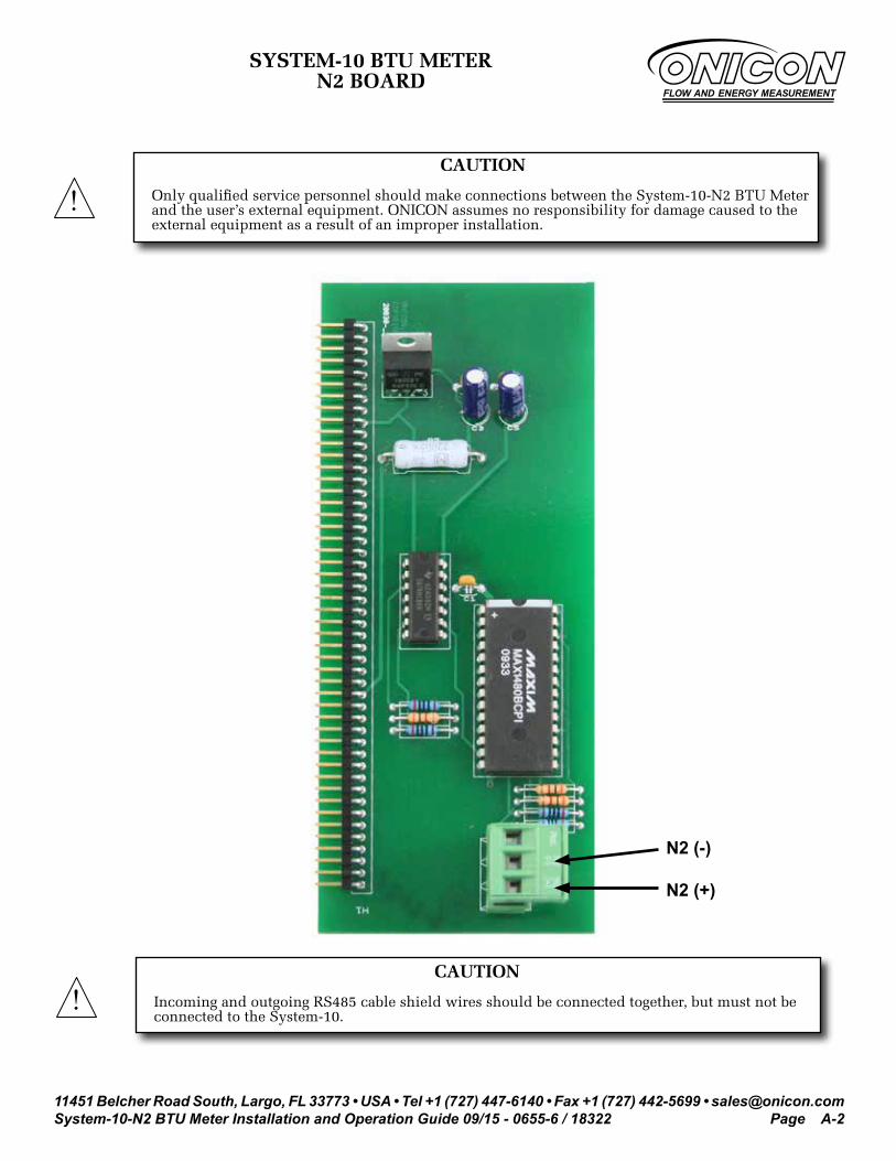
SYSTEM-10 BTU METER N2 BOARD
CAUTION
Only qualified service personnel should make connections between the System-10-N2 BTU Meter and the user’s external equipment. ONICON assumes no responsibility for damage caused to the external equipment as a result of an improper installation.
!
CAUTION
Incoming and outgoing RS485 cable shield wires should be connected together, but must not be connected to the System-10.
!
N2 (-)
N2 (+)
FLOW AND ENERGY MEASUREMENT
11451 Belcher Road South, Largo, FL 33773 • USA • Tel +1 (727) 447-6140 • Fax +1 (727) 442-5699 • [email protected] BTU Meter Installation and Operation Guide 09/15 - 0655-6 / 18322 Page A-3
+-
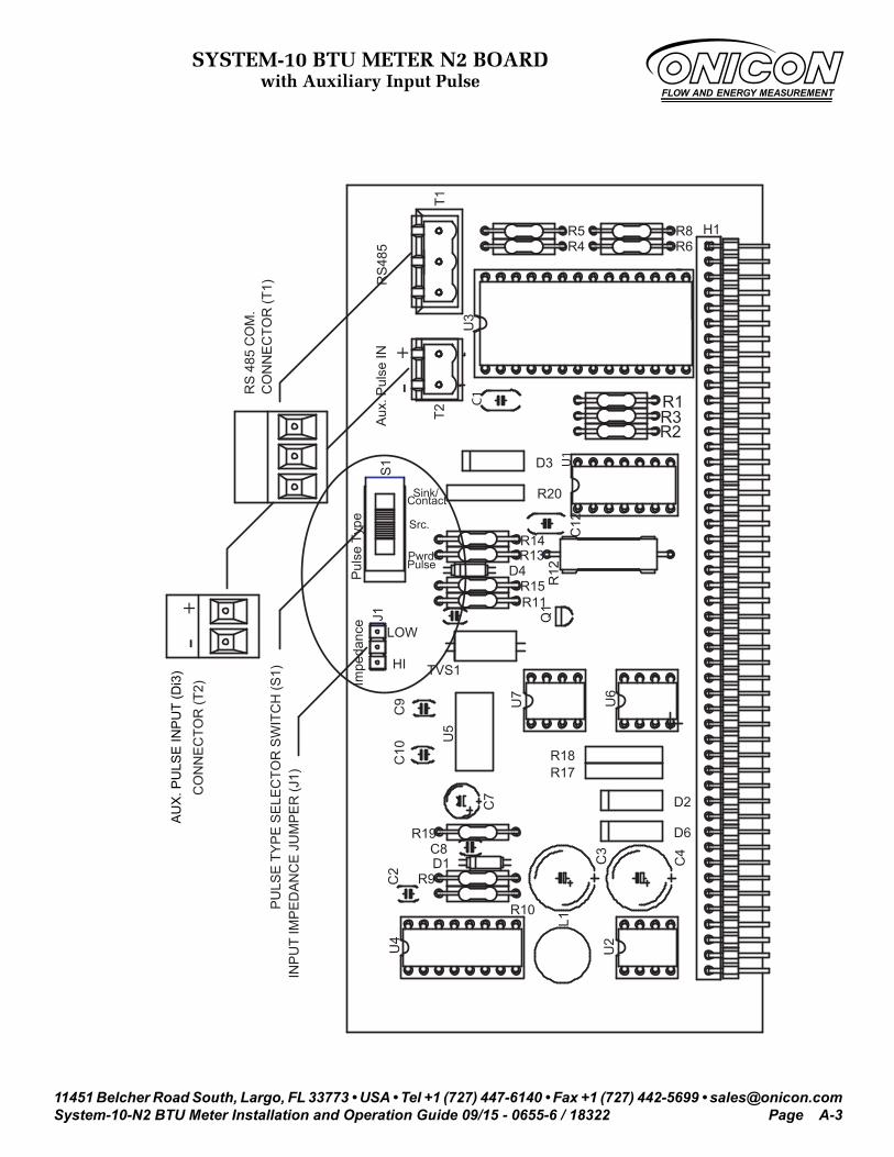
INP
UT
IMP
ED
AN
CE
JU
MP
ER
(J1)
PU
LSE
TY
PE
SE
LEC
TOR
SW
ITC
H (S
1)C
ON
NE
CTO
R (T
1)R
S 4
85 C
OM
.
CO
NN
EC
TOR
(T2)
AU
X. P
ULS
E IN
PU
T
R6R8
R4R5
Pul
se T
ype
-
C1
T2Aux
. Pul
se IN +
R3R1
R2
U3
Sink/
Src.
Contact R20
Pwrd.Pulse
LOW
R15R11
D4
R14R13
C12
U1
Q1
R12
D3S1
HI
C9
C10
C7
U5
U6
D2
R17R18
U7
C2
R10
D1R9
U4
C4
U2
L1
C3
R19C8
D6
J1
TVS1
Impe
danc
e
T1
H1
RS
485
SY
STE
M-1
0-N
2 B
TU M
ETE
RN
2 B
OA
RD
WIT
H A
UX
ILIA
RY
INP
UT
PU
LSE
12-8-04
A-12
0458
SYSTEM-10 BTU METER N2 BOARDwith Auxiliary Input Pulse
AU
X. P
ULS
E IN
PU
T (D
i3)
FLOW AND ENERGY MEASUREMENT

![PDF [727 KB]](https://cdn.vdocument.in/doc/165x107/586f55111a28ab3f228bbd63/pdf-727-kb.jpg)


