— ABB Limited Measurement & AnalyticsHoward Road, St. Neots Cambridgeshire, PE19 8EUUK Tel: +44 (0)870 600 6122 Fax: +44 (0)1480 213 339 Email: [email protected]
ABB Automation Products GmbH Measurement & AnalyticsSchillerstr. 72 32425 Minden Germany Tel: +49 571 830-0 Fax: +49 571 830-1806
abb.com/actuators
ABB Inc. Measurement & Analytics125 E. County Line Road Warminster, PA 18974 USA Tel: +1 215 674 6000 Fax: +1 215 674 7183
DS7
RH
D50
0/R
HD
800
-EN
Rev
. D
08.
2018
— We reserve the right to make technical changes or modify the contents of this document without prior notice. With regard to purchase orders, the agreed particulars shall prevail. ABB does not accept any responsibility whatsoever for potential errors or possible lack of information in this document. We reserve all rights in this document and in the subject matter and illustrations contained therein. Any reproduction, disclosure to third parties or utilization of its contents – in whole or in parts – is forbidden without prior written consent of ABB.Copyright© 2018 ABB All rights reserved 3KXE111002R1001
— ABB MEASUREMENT & ANALYTICS | DATA SHEET
RHD500 / RHD800 (Contrac) Electrical rotary actuator

2 RHD500 / RHD800 (CONTRAC) ELECTRICAL ROTARY ACTUATOR | DS7RHD500/RHD800-EN REV. D RHD500 / RHD800 (CONTRAC) ELECTRICAL ROTARY ACTUATOR | DS7RHD500/RHD800-EN REV. D 19
— For continuous control mode, nominal torque 500 / 800 Nm (400 / 600 lbf-ft)
— Process optimization thanks to maximum control precision
— Maintenance-free up to 10 years
— Electrical actuator for continuous positioning, three-point position control, or bus control
— Stall-proof without the need for position- or torque-dependent shut-off
— Adjustable mechanical limit stops for defined operating range
— Handwheel for emergency operation
— Signal and power input only via separate, microprocessor-controlled electronic unit
— Power supply 115 V AC or 230 V AC via electronic unit only
RHD500 / RHD800 (CONTRAC) ELECTRICAL ROTARY ACTUATOR | DS7RHD500/RHD800-EN REV. D 3
Change from one to two columns
— Brief description
Compact actuator for the operation of final control elements with rotary movement such as valve flaps, ball valves, etc. The torque is transferred via a lever-type actuator or the actuator is directly coupled to the shaft of the final control element. The actuator is controlled using a Contrac electronic unit. This electronic unit serves as the interface between the actuator and the control system. During continuous positioning, the electronic unit varies the motor torque steplessly until the actuator force and the control valve force are balanced. High response sensitivity and high positioning accuracy with short positioning time ensure an excellent control quality and a long actuator life.
Operating principles
The actuator continuously responds to a set point signal. The motor is permanently under voltage (operating mode S9 - 100 % stall-proof according to IEC 60034-1 / EN 60034-1) and gently increases or reduces the torque on the electronic unit in proportion to the ΔY signal (the difference between the Y set point and the Y position signal). The actuator is not subject to temperature derating, i.e., there are no restrictions, even at the maximum permissible ambient temperature. Where a state of balance exists, the actuator force and process force are equivalent and the actuator keeps the final control element in the required position. The classification of the ‘S9 - 100 % overload protected’ Contrac actuator in accordance with IEC 60034-1 / EN 60034-1 by far exceeds the requirements for the highest class, ‘continuous modulation, class D’ in accordance with EN 15714-2. The Contrac actuator offers extensive process optimization capabilities thanks to its high-precision and highly dynamic operation.
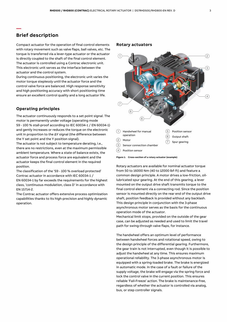
Rotary actuators
M10982
1 2
3
4
7
6
6
1 Handwheel for manual
operation
2 Motor
3 Sensor connection chamber
4 Position sensor
5 Position sensor
6 Output shaft
7 Spur gearing
Figure 1: Cross-section of a rotary actuator (example)
Rotary actuators are available for nominal actuator torque from 50 to 16000 Nm (40 to 12000 lbf-ft) and feature a common design principle. A motor drives a low-friction, oil-lubricated spur gearing. At the end of this gearing, a lever mounted on the output drive shaft transmits torque to the final control element via a connecting rod. Since the position sensor is mounted directly on the rear end of the output drive shaft, position feedback is provided without any backlash. This design principle in conjunction with the 3-phase asynchronous motor serves as the basis for the continuous operation mode of the actuator. Mechanical limit stops, provided on the outside of the gear case, can be adjusted as needed and used to limit the travel path for swing-through valve flaps, for instance. The handwheel offers an optimum level of performance between handwheel forces and rotational speed, owing to the design principle of the differential gearing. Furthermore, the gear train is not interrupted, even though it is possible to adjust the handwheel at any time. This ensures maximum operational reliability. The 3-phase asynchronous motor is equipped with a spring-loaded brake. The brake is energized in automatic mode. In the case of a fault or failure of the supply voltage, the brake will engage via the spring force and lock the control valve in the current position. This ensures reliable ‘Fail-Freeze’ action. The brake is maintenance-free, regardless of whether the actuator is controlled via analog, bus, or step controller signals.
4 RHD500 / RHD800 (CONTRAC) ELECTRICAL ROTARY ACTUATOR | DS7RHD500/RHD800-EN REV. D
— … Brief description
Analog signal and power input
For analog control, the set point entry is received from the control system through a 0 to 20 mA or 4 to 20 mA current value. Signal monitoring is possible. Should the signal leave the pre-defined limits, the actuator will perform the set safety procedure (e. g. ‘Lock in last position’ or ‘Drive to safety position’). The position feedback is also given through a 0 to 20 mA or 4 to 20 mA feedback signal. There are 3 digital inputs and 3 digital outputs available in addition to the analog signal. If a digital input is activated, it will take priority over the set point signal (manual mode takes priority over automatic mode). The following digital input configurations are possible:
Configuration Digital input 1 Digital input 2 Digital input 3
OFF No function No function No function
Manual
intervention
Manual mode /
Automatic mode
switching
Travel command in
OPEN direction
Travel command
in CLOSE direction
Rapid traverse Rapid traverse
mode / Automatic
mode switching
Rapid traverse
travel command in
OPEN direction
Rapid traverse
travel command in
CLOSE direction
Step controller ON / OFF step
controller activation
Step controller
pulses in OPEN
direction
Step controller
pulses in CLOSE
direction
The digital output function is freely selectable for each output. The following functions are available:
Function Description
Ready to operate Signaling of device status.
Signal end position 0 % Actuator has reached the 0 % position.
Signal end position
100 %
Actuator has reached the 100 % position.
Signal limit value 1 rising While the signal level is rising, the actuator has
reached the position defined as limit value 1.
Signal limit value 1
falling
While the signal level is falling, the actuator has
reached the position defined as limit value 1.
Signal limit value 2 rising While the signal level is rising, the actuator has
reached the position defined as limit value 2.
Signal limit value 2
falling
While the signal level is falling, the actuator has
reached the position defined as limit value 2.
Collective failure Drive function is no longer given. The actuator is
no longer available.
Collective alarm Parameters in the Contrac interface system have
adopted values, which make a failure in the near
future likely. The actuator remains functional.
Local operation The actuator is operated via the local control
station (ISF)
Rapid traverse +
direction
Actuator is moving at rapid traverse speed in +
direction (only for 2-motor version).
Rapid traverse control
−direction
Actuator is moving at rapid traverse speed in −
direction (only for 2-motor version).
Step controller operation
In the ‘step controller’ operating mode the incoming control commands are received as pulses at digital inputs 2 and 3 these are upward-integrated into an internal memory. The memory uses these pulses to generate an ‘artificial’ internal set point which the actuator then follows. This process is as easy on the control valve and actuator operation as the analog control process.
RHD500 / RHD800 (CONTRAC) ELECTRICAL ROTARY ACTUATOR | DS7RHD500/RHD800-EN REV. D 5
Rapid traverse mode
The actuator is operated exactly in the same operating mode as in the analog control mode. On activation of digital inputs 2 or 3, the actuator moves at twice the rated operating speed and half the torque in the corresponding direction. Just before the end position is reached, the actuator travel speed is automatically switched back to the set speed, at which the remaining distance is covered.
Speed
Contrac actuators offer different speed adjustments for both directions, independently of actuator torque or actuator force. Furthermore, a speed characteristics curve can be set with three different speed values for each direction. The actuator speed is steplessly adapted to the rate of change in speed of the set point value. This ensures a highly dynamic and extremely precise control process. In order to preserve the control valve, the actuator speed is automatically reduced before the end position is reached.
Torque/Force
The torque and actuator force setting options are comparable to the speed setting options. 50 %, 75 % and 100 % of the rated output value can be selected. The electronic unit alters the motor actuation according to the selected value.
Set point monitoring
The set point can be monitored for compliance with the adjustable limit values. Should the set point exceed the upper limit value or fall below the lower limit value, the actuator will perform the previously defined safety action. ‘Lock in current Position’ or ‘Move to pre-defined safety position’ are available as safety actions.
Ambient conditions
Temperature Different temperature versions are available, depending on the actuator type. The power-up period is not subject to derating, i.e. even at the maximum permissible ambient temperature, the actuator ensures maximum control precision and dynamics during a power-up period of 100 %. Corrosion protection Contrac actuators and electronic units have been designed for operation in extreme ambient conditions. They satisfy the requirements of atmospheric corrosivity category C5-I (highly polluted industrial atmospheres) for protection against external corrosion in accordance with DIN EN 15714 (Electric actuators for industrial valves – Basic requirements), and EN ISO 12944-2:1998 (Paints and varnishes. Corrosion protection of steel structures by protective paint systems. Classification of environments). Electronic cabinet modules satisfy the requirements of category C1 (low pollution) as per EN ISO 12944-2:1998 (Paints and varnishes. Corrosion protection of steel structures by protective paint systems. Classification of environments). Service life Contrac actuators and electronic units exceed the service life requirements for the highest class D, ‘continuous modulation’, as per DIN EN 15714 (Electric actuators for industrial valves – Basic requirements). The actuators remain maintenance-free for up to 10 years under ‘normal’ load.

6 RHD500 / RHD800 (CONTRAC) ELECTRICAL ROTARY ACTUATOR | DS7RHD500/RHD800-EN REV. D
— Communication
The PROFIBUS DP®, PROFIBUS DP®/V1 or HART® communication protocols are available for digital communication. PROFIBUS®
PROFIBUS DP® is an international, open field bus protocol which has been standardized in the field bus standard EN 50170. On a cyclic basis, the master reads the input information from the slaves and writes the output information to the slaves. In addition to this cyclic data transfer of the process representation (e. g. setpoint and actual value), Profibus DP also provides powerful functions for diagnostics and commissioning. PROFIBUS DP/V1 additionally offers the acyclic transfer of data for the configuration of slaves, for example. Data traffic is monitored through the monitoring functions on the master and slave sides. In addition to PROFIBUS® data transfer, ABB Contrac actuators provide two configurable binary outputs to for example signal that the end position has been reached. The two configurable digital outputs can be used independently of the bus communication. HART®
Contrac actuators also offer the option of using the HART® communication protocol for configuration and parameterization while operation is in progress. HART®-FSK communication enables simultaneous analog set point transmission and digital communication without additional installation. The HART signal is modulated on to the 4 to 20 mA analog set point signal. The HART® protocol works with Frequency Shift Keying (FSK) technology, based on the Bell 202 communication standard.
DTM
The DTM (Device Type Manager) for Contrac actuators is based on FDT / DTM technology (FDT 1.2 / 1.2.1) and can either be integrated into a control system or loaded on a PC with DAT200 Asset Vision Basic. This allows you to work with the same user interface in the commissioning phase, during operation, and for servicing tasks, involving monitoring the device, setting parameters, and reading out data. Communication is based on HART® protocol or PROFIBUS® communication. Reading out data from the device has no effect on the operation in progress. Newly set parameters are saved in the non-volatile memory directly upon download to the device, and become active immediately. EDD
Similar to DTM, the EDD (Electronic Device Description) provides the option of configuration and parameterization of the device through HART® communication by using a handheld terminal or an EDD integrated in the system.
Change from two to one column
RHD500 / RHD800 (CONTRAC) ELECTRICAL ROTARY ACTUATOR | DS7RHD500/RHD800-EN REV. D 7
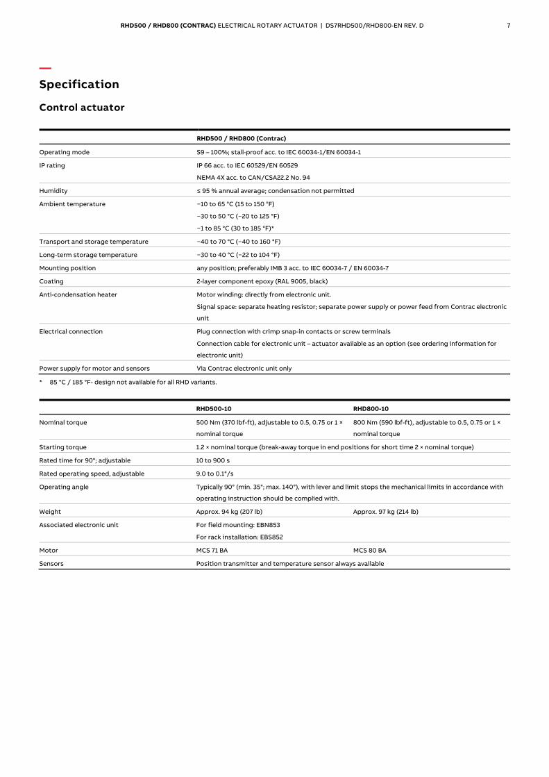
— Specification
Control actuator
RHD500 / RHD800 (Contrac)
Operating mode S9 – 100%; stall-proof acc. to IEC 60034-1/EN 60034-1
IP rating IP 66 acc. to IEC 60529/EN 60529
NEMA 4X acc. to CAN/CSA22.2 No. 94
Humidity ≤ 95 % annual average; condensation not permitted
Ambient temperature −10 to 65 °C (15 to 150 °F)
−30 to 50 °C (−20 to 125 °F)
−1 to 85 °C (30 to 185 °F)*
Transport and storage temperature −40 to 70 °C (−40 to 160 °F)
Long-term storage temperature −30 to 40 °C (−22 to 104 °F)
Mounting position any position; preferably IMB 3 acc. to IEC 60034-7 / EN 60034-7
Coating 2-layer component epoxy (RAL 9005, black)
Anti-condensation heater Motor winding: directly from electronic unit.
Signal space: separate heating resistor; separate power supply or power feed from Contrac electronic
unit
Electrical connection Plug connection with crimp snap-in contacts or screw terminals
Connection cable for electronic unit – actuator available as an option (see ordering information for
electronic unit)
Power supply for motor and sensors Via Contrac electronic unit only
* 85 °C / 185 °F- design not available for all RHD variants.
RHD500-10 RHD800-10
Nominal torque 500 Nm (370 lbf-ft), adjustable to 0.5, 0.75 or 1 ×
nominal torque
800 Nm (590 lbf-ft), adjustable to 0.5, 0.75 or 1 ×
nominal torque
Starting torque 1.2 × nominal torque (break-away torque in end positions for short time 2 × nominal torque)
Rated time for 90°; adjustable 10 to 900 s
Rated operating speed, adjustable 9.0 to 0.1°/s
Operating angle Typically 90° (min. 35°; max. 140°), with lever and limit stops the mechanical limits in accordance with
operating instruction should be complied with.
Weight Approx. 94 kg (207 lb) Approx. 97 kg (214 lb)
Associated electronic unit For field mounting: EBN853
For rack installation: EBS852
Motor MCS 71 BA MCS 80 BA
Sensors Position transmitter and temperature sensor always available
8 RHD500 / RHD800 (CONTRAC) ELECTRICAL ROTARY ACTUATOR | DS7RHD500/RHD800-EN REV. D
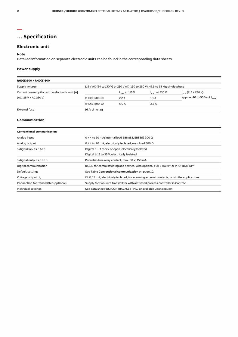
— … Specification
Electronic unit
Note Detailed information on separate electronic units can be found in the corresponding data sheets.
Power supply
RHD(E)500 / RHD(E)800
Supply voltage 115 V AC (94 to 130 V) or 230 V AC (190 to 260 V); 47.5 to 63 Hz; single-phase
Current consumption at the electronic unit [A]
(AC 115 V / AC 230 V)
lmax at 115 V lmax at 230 V lpos (115 + 230 V):
approx. 40 to 50 % of lmax RHD(E)500-10 2.2 A 1.1 A
RHD(E)800-10 5.0 A 2.5 A
External fuse 16 A; time-lag
Communication
Conventional communication
Analog input 0 / 4 to 20 mA; internal load EBN853, EBS852 300 Ω
Analog output 0 / 4 to 20 mA, electrically isolated, max. load 500 Ω
3 digital inputs, 1 to 3 Digital 0: −3 to 5 V or open, electrically isolated
Digital 1: 12 to 35 V, electrically isolated
3 digital outputs, 1 to 3 Potential-free relay contact, max. 60 V, 150 mA
Digital communication RS232 for commissioning and service, with optional FSK / HART® or PROFIBUS DP®
Default settings See Table Conventional communication on page 10.
Voltage output UV 24 V, 15 mA, electrically isolated, for scanning external contacts, or similar applications
Connection for transmitter (optional) Supply for two-wire transmitter with activated process controller in Contrac
Individual settings See data sheet ‘DS/CONTRAC/SETTING’ or available upon request.
RHD500 / RHD800 (CONTRAC) ELECTRICAL ROTARY ACTUATOR | DS7RHD500/RHD800-EN REV. D 9
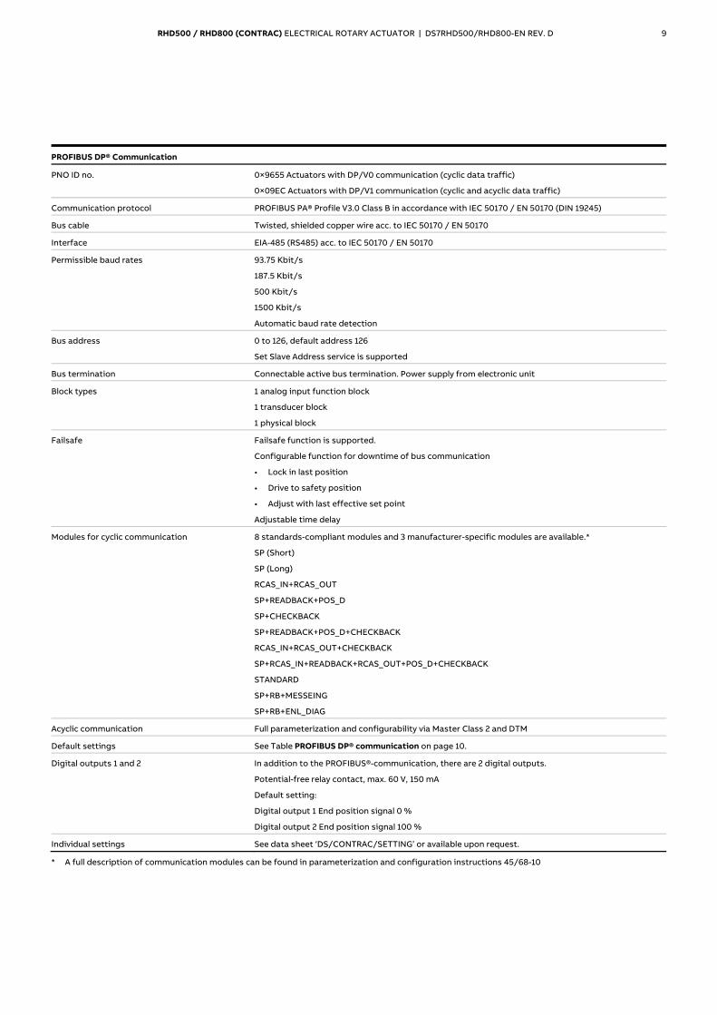
PROFIBUS DP® Communication
PNO ID no. 0×9655 Actuators with DP/V0 communication (cyclic data traffic)
0×09EC Actuators with DP/V1 communication (cyclic and acyclic data traffic)
Communication protocol PROFIBUS PA® Profile V3.0 Class B in accordance with IEC 50170 / EN 50170 (DIN 19245)
Bus cable Twisted, shielded copper wire acc. to IEC 50170 / EN 50170
Interface EIA-485 (RS485) acc. to IEC 50170 / EN 50170
Permissible baud rates 93.75 Kbit/s
187.5 Kbit/s
500 Kbit/s
1500 Kbit/s
Automatic baud rate detection
Bus address 0 to 126, default address 126
Set Slave Address service is supported
Bus termination Connectable active bus termination. Power supply from electronic unit
Block types 1 analog input function block
1 transducer block
1 physical block
Failsafe Failsafe function is supported.
Configurable function for downtime of bus communication
• Lock in last position
• Drive to safety position
• Adjust with last effective set point
Adjustable time delay
Modules for cyclic communication 8 standards-compliant modules and 3 manufacturer-specific modules are available.*
SP (Short)
SP (Long)
RCAS_IN+RCAS_OUT
SP+READBACK+POS_D
SP+CHECKBACK
SP+READBACK+POS_D+CHECKBACK
RCAS_IN+RCAS_OUT+CHECKBACK
SP+RCAS_IN+READBACK+RCAS_OUT+POS_D+CHECKBACK
STANDARD
SP+RB+MESSEING
SP+RB+ENL_DIAG
Acyclic communication Full parameterization and configurability via Master Class 2 and DTM
Default settings See Table PROFIBUS DP® communication on page 10.
Digital outputs 1 and 2 In addition to the PROFIBUS®-communication, there are 2 digital outputs.
Potential-free relay contact, max. 60 V, 150 mA
Default setting:
Digital output 1 End position signal 0 %
Digital output 2 End position signal 100 %
Individual settings See data sheet ‘DS/CONTRAC/SETTING’ or available upon request.
* A full description of communication modules can be found in parameterization and configuration instructions 45/68-10
Change from one to two columns
10 RHD500 / RHD800 (CONTRAC) ELECTRICAL ROTARY ACTUATOR | DS7RHD500/RHD800-EN REV. D
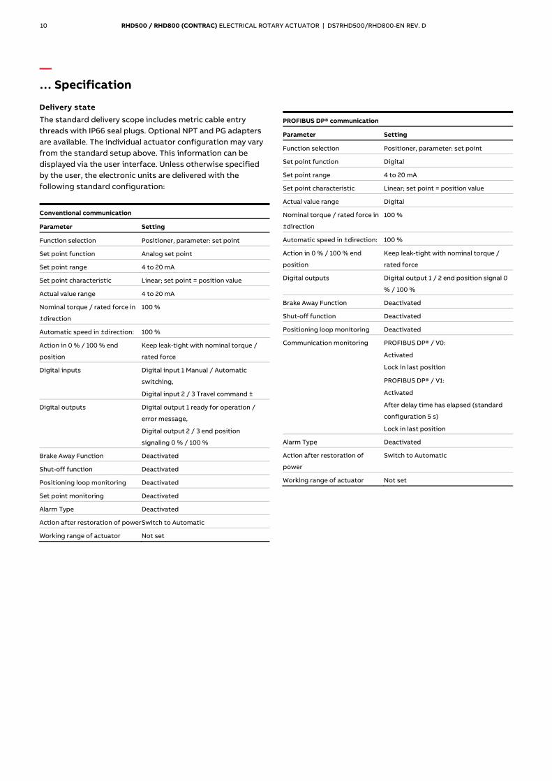
— … Specification
Delivery state
The standard delivery scope includes metric cable entry threads with IP66 seal plugs. Optional NPT and PG adapters are available. The individual actuator configuration may vary from the standard setup above. This information can be displayed via the user interface. Unless otherwise specified by the user, the electronic units are delivered with the following standard configuration:
Conventional communication
Parameter Setting
Function selection Positioner, parameter: set point
Set point function Analog set point
Set point range 4 to 20 mA
Set point characteristic Linear; set point = position value
Actual value range 4 to 20 mA
Nominal torque / rated force in
±direction
100 %
Automatic speed in ±direction: 100 %
Action in 0 % / 100 % end
position
Keep leak-tight with nominal torque /
rated force
Digital inputs Digital input 1 Manual / Automatic
switching,
Digital input 2 / 3 Travel command ±
Digital outputs Digital output 1 ready for operation /
error message,
Digital output 2 / 3 end position
signaling 0 % / 100 %
Brake Away Function Deactivated
Shut-off function Deactivated
Positioning loop monitoring Deactivated
Set point monitoring Deactivated
Alarm Type Deactivated
Action after restoration of power Switch to Automatic
Working range of actuator Not set
PROFIBUS DP® communication
Parameter Setting
Function selection Positioner, parameter: set point
Set point function Digital
Set point range 4 to 20 mA
Set point characteristic Linear; set point = position value
Actual value range Digital
Nominal torque / rated force in
±direction
100 %
Automatic speed in ±direction: 100 %
Action in 0 % / 100 % end
position
Keep leak-tight with nominal torque /
rated force
Digital outputs Digital output 1 / 2 end position signal 0
% / 100 %
Brake Away Function Deactivated
Shut-off function Deactivated
Positioning loop monitoring Deactivated
Communication monitoring PROFIBUS DP® / V0:
Activated
Lock in last position
PROFIBUS DP® / V1:
Activated
After delay time has elapsed (standard
configuration 5 s)
Lock in last position
Alarm Type Deactivated
Action after restoration of
power
Switch to Automatic
Working range of actuator Not set
RHD500 / RHD800 (CONTRAC) ELECTRICAL ROTARY ACTUATOR | DS7RHD500/RHD800-EN REV. D 11
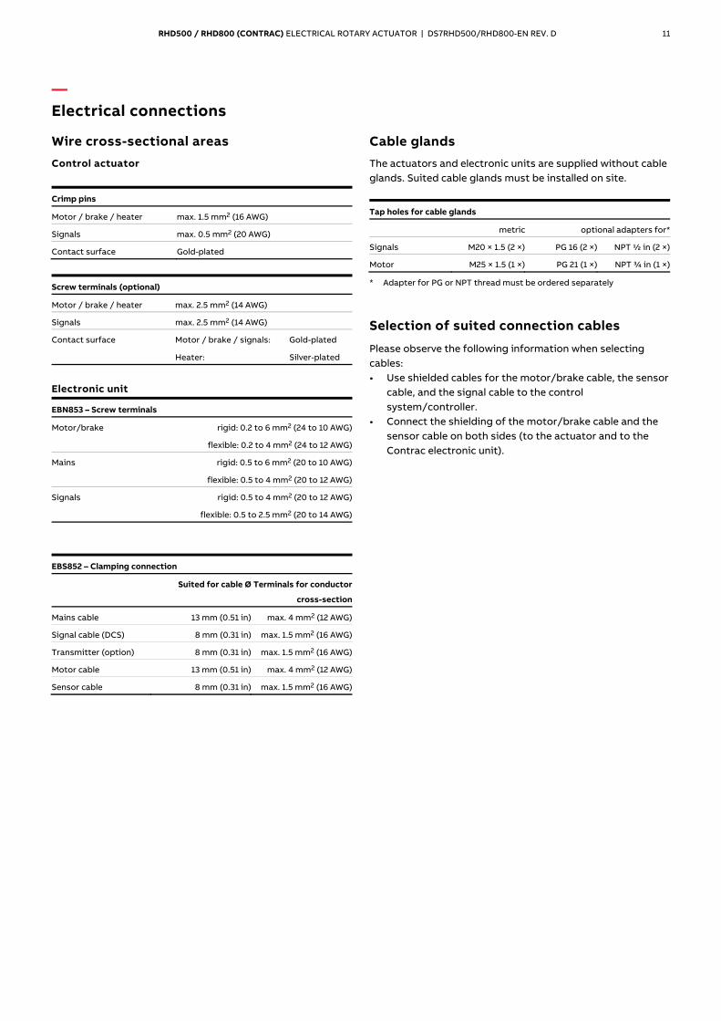
— Electrical connections
Wire cross-sectional areas
Control actuator
Crimp pins
Motor / brake / heater max. 1.5 mm2 (16 AWG)
Signals max. 0.5 mm2 (20 AWG)
Contact surface Gold-plated
Screw terminals (optional)
Motor / brake / heater max. 2.5 mm2 (14 AWG)
Signals max. 2.5 mm2 (14 AWG)
Contact surface Motor / brake / signals: Gold-plated
Heater: Silver-plated
Electronic unit
EBN853 – Screw terminals
Motor/brake rigid: 0.2 to 6 mm2 (24 to 10 AWG)
flexible: 0.2 to 4 mm2 (24 to 12 AWG)
Mains rigid: 0.5 to 6 mm2 (20 to 10 AWG)
flexible: 0.5 to 4 mm2 (20 to 12 AWG)
Signals rigid: 0.5 to 4 mm2 (20 to 12 AWG)
flexible: 0.5 to 2.5 mm2 (20 to 14 AWG)
EBS852 – Clamping connection
Suited for cable Ø Terminals for conductor
cross-section
Mains cable 13 mm (0.51 in) max. 4 mm2 (12 AWG)
Signal cable (DCS) 8 mm (0.31 in) max. 1.5 mm2 (16 AWG)
Transmitter (option) 8 mm (0.31 in) max. 1.5 mm2 (16 AWG)
Motor cable 13 mm (0.51 in) max. 4 mm2 (12 AWG)
Sensor cable 8 mm (0.31 in) max. 1.5 mm2 (16 AWG)
Cable glands
The actuators and electronic units are supplied without cable glands. Suited cable glands must be installed on site.
Tap holes for cable glands
metric optional adapters for*
Signals M20 × 1.5 (2 ×) PG 16 (2 ×) NPT ½ in (2 ×)
Motor M25 × 1.5 (1 ×) PG 21 (1 ×) NPT ¾ in (1 ×)
* Adapter for PG or NPT thread must be ordered separately
Selection of suited connection cables
Please observe the following information when selecting cables: • Use shielded cables for the motor/brake cable, the sensor
cable, and the signal cable to the control system/controller.
• Connect the shielding of the motor/brake cable and the sensor cable on both sides (to the actuator and to the Contrac electronic unit).
Change from two to one column
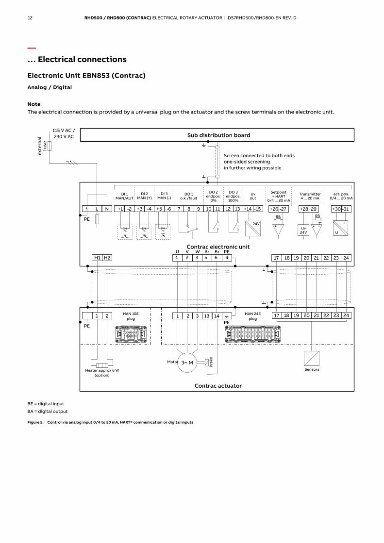
12 RHD500 / RHD800 (CONTRAC) ELECTRICAL ROTARY ACTUATOR | DS7RHD500/RHD800-EN REV. D
— … Electrical connections
Electronic Unit EBN853 (Contrac)
Analog / Digital
Note The electrical connection is provided by a universal plug on the actuator and the screw terminals on the electronic unit.
M10062
+28 29
RB
+ -Uv
24V
24V
+26 -27
RB
+ -
+30 -31
I
U
7 8 9 11 12 13 +14 -1510
1 2 3 5 6
1 2 3 13 14
17 18 19 20 2221 2423
17 19 20 2221 24231 2
L N
3~ M
PE
PE
PE
+1 -2 +3 -4 +5 -6
109876
1 2 3 4 5
PE
18
H1 H2
U V W Br Br
4
Motor
Bra
ke
Contrac actuator
SensorsHeater approx 6 W
(option)
Screen connected to both ends
one-sided screening
in further wiring possible
Transmitter4 ... 20 mA
Setpoint+ HART
0/4 ... 20 mA
act. pos.0/4 ... 20 mA
DO 1o.k./fault
DO 2endpos.
0%
DO 3endpos.
100%
DI 1/MAN AUT
DI 2(+)MAN
DI 3(-)MAN
Uvout
Sub distribution board
Contrac electronic unit
ex
tern
al
fus
e
115 V /AC
230 V AC
HAN 10E
plug
HAN 24E
plug
BE = digital input
BA = digital output
Figure 2: Control via analog input 0/4 to 20 mA, HART® communication or digital inputs
RHD500 / RHD800 (CONTRAC) ELECTRICAL ROTARY ACTUATOR | DS7RHD500/RHD800-EN REV. D 13
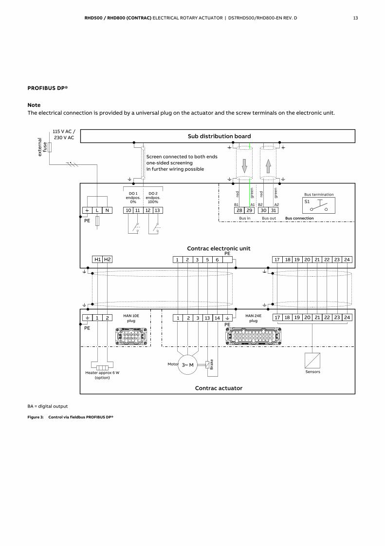
PROFIBUS DP®
Note The electrical connection is provided by a universal plug on the actuator and the screw terminals on the electronic unit.
M10230
1 2 3 5 6
1 2 3 13 14
17 18 19 20 2221 2423
17 19 20 2221 24231 2
L N
3~ M
PE
PE
PE
109876
1 2 3 4 5
PE
18
H1 H2
11 12 1310
S1
30 3128 29
B1 A1 B2 A2
Motor
Bra
ke
Contrac actuator
SensorsHeater approx 6 W
(option)
Screen connected to both ends
one-sided screening
in further wiring possible
DO 1endpos.
0%
DO 2endpos.
100%
Sub distribution board
Contrac electronic unit
ex
tern
al
fus
e
115 V /AC
230 V AC
HAN 10E
plug
HAN 24E
plug
red
gre
en
red
gre
en
Bus in Bus out
Bus termination
Bus connection
BA = digital output
Figure 3: Control via fieldbus PROFIBUS DP®
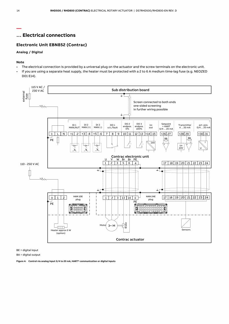
14 RHD500 / RHD800 (CONTRAC) ELECTRICAL ROTARY ACTUATOR | DS7RHD500/RHD800-EN REV. D
— … Electrical connections
Electronic Unit EBN852 (Contrac)
Analog / Digital
Note • The electrical connection is provided by a universal plug on the actuator and the screw terminals on the electronic unit. • If you are using a separate heat supply, the heater must be protected with a 2 to 6 A medium time-lag fuse (e.g. NEOZED
D01 E14).
M10216
+28 29
RB
+ -Uv
24V
24V
+26 -27
RB
+ -
+30 -31
I
U
7 8 9 11 12 13 +14 -1510
1 2 3 5 6
1 2 3 13 14
17 18 19 20 2221 2423
17 19 20 2221 24231 2
L N
3~ M
PE
PE
PE
+1 -2 +3 -4 +5 -6
109876
1 2 3 4 5
PE
18
4
U V W Br Br
Motor
Bra
ke
Contrac actuator
SensorsHeater approx 6 W
(option)
Screen connected to both ends
one-sided screening
in further wiring possible
Transmitter4 ... 20 mA
Setpoint+ HART
0/4 ... 20 mA
act. pos.0/4 ... 20 mA
DO 1o.k./fault
DO 2endpos.
0%
DO 3endpos.
100%
DI 1/MAN AUT
DI 2(+)MAN
DI 3(-)MAN
Uvout
Sub distribution board
Contrac electronic unit
ex
tern
al
fus
e
115 V /AC
230 V AC
110 - 250 V AC
HAN 10E
plug
HAN 24E
plug
BE = digital input
BA = digital output
Figure 4: Control via analog input 0/4 to 20 mA, HART® communication or digital inputs
RHD500 / RHD800 (CONTRAC) ELECTRICAL ROTARY ACTUATOR | DS7RHD500/RHD800-EN REV. D 15
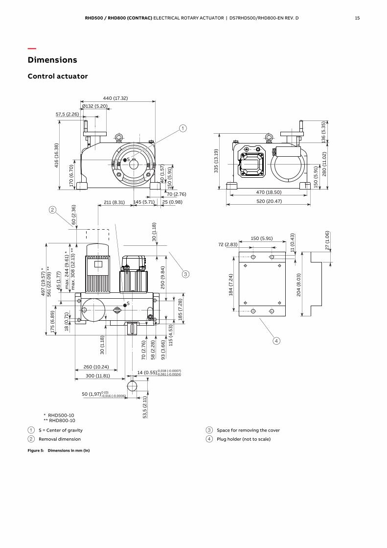
— Dimensions
Control actuator
M11050
70
(2
.76
)
30
(1.
18)
260 (10.24)
300 (11.81)
S
14 (0.55)
50 (1,97)
53
,5 (
2.1
1)
25
0 (
9.8
4)
30
(1.
18)
58
(2
.28
)
93
(3
.66
)
115
(4
.53
)
45
(1.
77
)
185
(7
.28
)
ma
x.
30
8 (
12.1
3)
**
49
7 (
19.5
7)
*
18 (
0.7
1)
175
(6
.89
)
60
(2
.36
)
-0,018 (-0.0007)-0,061 (-0.0024)
0 (0)-0,016 (-0.0006)
40
(1.
57
)
Ø132 (5.20)
440 (17.32)
57,5 (2.26)
416
(16
.38
)
150
(5
.91)
170
(6
.70
)
145 (5.71) 25 (0.98)211 (8.31)
70 (2.76)
S
150
(5.9
1)
28
0(1
1.0
2)
136
(5.3
5)
470 (18.50)
33
5(1
3.1
9)
520 (20.47)
11(0
.43
)
150 (5.91)
72 (2.83)
20
4(8
.03
)
27
(1.0
6)
184
(7.2
4)
56
1 (2
2.0
9)
**
ma
x.
24
4 (
9.6
1) *
* RHD500-10** RHD800-10
3
4
2
1
1 S = Center of gravity
2 Removal dimension
3 Space for removing the cover
4 Plug holder (not to scale)
Figure 5: Dimensions in mm (in)
16 RHD500 / RHD800 (CONTRAC) ELECTRICAL ROTARY ACTUATOR | DS7RHD500/RHD800-EN REV. D
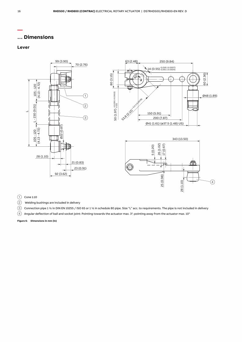
— … Dimensions
Lever
M11043
L
45°
14 (0.55)-0,018 (-0.0007)-0,061 (-0.0024)
53,8 (2
.12)
+ 0,2
(+0.0
078)
105
-12
0
(4.1
3-
4.7
2)
Ø2
2(0
.87
)
23 (0.91)
21 (0.83)
92 (3.62)
28 (1.10)
L-
23
0(9
.01)
99 (3.90)70 (2.76)
28
(1.1
0)
5(0
.20
)
25
(0.9
8)
343 (13.50)
26
(1.0
2)
17(0
.67
)
80
(3.1
5)
50
(1.9
7)
+0
.03
9(+
0.0
015
)0
(0)
60
(2.3
6)
150 (5.91)
200 (7.87)
250 (9.84)63 (2.48)
Ø48 (1.89)
Ø41 (1.61) (ø37.5 (1.48) US)
105
-12
0
(4.1
3-
4.7
2)
3
2
4
1
1 Cone 1:10
2 Welding bushings are included in delivery
3 Connection pipe 1 ½ in DIN EN 10255 / ISO 65 or 1 ½ in schedule 80 pipe. Size “L” acc. to requirements. The pipe is not included in delivery
4 Angular deflection of ball and socket joint: Pointing towards the actuator max. 3°; pointing away from the actuator max. 10°
Figure 6: Dimensions in mm (in)

RHD500 / RHD800 (CONTRAC) ELECTRICAL ROTARY ACTUATOR | DS7RHD500/RHD800-EN REV. D 17
— Ordering Information
RHD500 / RHD800
Basic model
RHD500 Rotary Actuator, rated torque 500 Nm (400 ft-lbs) (adjustable to 50 % / 75 % / 100 %) V68163 XXXX XXX XXX XXX
RHD800 Rotary Actuator, rated torque 800 Nm (600ft-lbs) (adjustable to 50 % / 75 % / 100 %) V68164 XXXX XXX XXX XXX
Rated Pos. Speed
9.0°/s (adjustable to 9.0 to 0.1°/s), only for RHD500 0111
9.0°/s (adjustable to 9.0 to 0.1°/s), only for RHD800 0112
Mechanical Connection
Shaft with key 370
Lever set, standard design (consists of lever, 2 ball-and-socket joints and 2 welding bushings) 496
Lever set, US design (consists of lever, 2 ball-and-socket joints and 2 US welding bushings) 374
Electrical Connection
Plug (24-pole) complete, crimped 277
Plug (24-pole) complete, terminals 278
Plug bottom part covered 279*
Ambient Temperature Range
−10 to 65 °C (15 to 150 °F) 344
−30 to 50 °C (−22 to 125 °F) 341
−1 to 85 °C (30 to 185 °F) 349
* Female plug with cables to be ordered with electronic unit
18 RHD500 / RHD800 (CONTRAC) ELECTRICAL ROTARY ACTUATOR | DS7RHD500/RHD800-EN REV. D
— … Ordering Information Additional ordering information RHD500 / RHD800
RHD500 / RHD800 Rotary Actuator XXX XXX XXX XXX XXX XXX XXX XXX XXX
Electrical Connection Thread
Set NPT adapter (junction metric / NPT thread) 680
Set PG adapter (junction metric / PG thread) 681
Anti-condensation Heater
Anti-condensation heater 360
Identification on Data Label
Alphanumeric, max. 32 characters 294
Data Label with US Units
Data label with US units 253
Accessories: Plug Cover
Cover for male plug (24 pole) 337
Accessories: Plug Holder
Plug holder 338
Factory Certificate 2.1 acc. to EN 10204
Factory certificate 2.1 acc. EN 10204 291
Certificate 3.1 acc. to EN 10204
Certificate 3.1 acc. EN 10204 292
Operating Instruction
German Z1D
English Z1E
Portuguese Z1P
Italian Z1I
French Z1F
Accessories
Description Order number
RHD(E) adapter plate for rotary actuators, type AP2 789191
Change from one to two columns
Sales Service
—
Trademarks
HART is a registered trademark of FieldComm Group, Austin, Texas, USA
PROFIBUS and PROFIBUS DP are registered trademarks of PROFIBUS &
PROFINET International (PI)

2 RHD500 / RHD800 (CONTRAC) ELECTRICAL ROTARY ACTUATOR | DS7RHD500/RHD800-EN REV. D RHD500 / RHD800 (CONTRAC) ELECTRICAL ROTARY ACTUATOR | DS7RHD500/RHD800-EN REV. D 19
— For continuous control mode, nominal torque 500 / 800 Nm (400 / 600 lbf-ft)
— Process optimization thanks to maximum control precision
— Maintenance-free up to 10 years
— Electrical actuator for continuous positioning, three-point position control, or bus control
— Stall-proof without the need for position- or torque-dependent shut-off
— Adjustable mechanical limit stops for defined operating range
— Handwheel for emergency operation
— Signal and power input only via separate, microprocessor-controlled electronic unit
— Power supply 115 V AC or 230 V AC via electronic unit only

— ABB Limited Measurement & AnalyticsHoward Road, St. Neots Cambridgeshire, PE19 8EUUK Tel: +44 (0)870 600 6122 Fax: +44 (0)1480 213 339 Email: [email protected]
ABB Automation Products GmbH Measurement & AnalyticsSchillerstr. 72 32425 Minden Germany Tel: +49 571 830-0 Fax: +49 571 830-1806
abb.com/actuators
ABB Inc. Measurement & Analytics125 E. County Line Road Warminster, PA 18974 USA Tel: +1 215 674 6000 Fax: +1 215 674 7183
DS7
RH
D50
0/R
HD
800
-EN
Rev
. D
08.
2018
— We reserve the right to make technical changes or modify the contents of this document without prior notice. With regard to purchase orders, the agreed particulars shall prevail. ABB does not accept any responsibility whatsoever for potential errors or possible lack of information in this document. We reserve all rights in this document and in the subject matter and illustrations contained therein. Any reproduction, disclosure to third parties or utilization of its contents – in whole or in parts – is forbidden without prior written consent of ABB.Copyright© 2018 ABB All rights reserved 3KXE111002R1001
— ABB MEASUREMENT & ANALYTICS | DATA SHEET
RHD500 / RHD800 (Contrac) Electrical rotary actuator


