
2010/09/13-17 INTDS2010 @ TRIUMFRIKEN Ayoshida : Beam spot temperature monitoring on production target of BigRIPS separator 1
Beam spot temperature monitoring onproduction target of BigRIPS separator
• Target system, targets in operation• Temperature monitoring
under high-radiation environment• Recent temperature data &
comparison with simulations (preliminary)
Atsushi Yoshida & Yoshiyuki Yanagisawa(BigRIPS team, RIKEN)
2010/09/13-17 INTDS2010 @ TRIUMFRIKEN Ayoshida : Beam spot temperature monitoring on production target of BigRIPS separator 2
RRCfRC
IRC
SRC
400
300
200
100
0
1 40 80 120 160 200 240
H O Ar Kr Xe Bi U
Atomic Mass
RRC
with fRC (IRC)
with fRC (SRC) 350 MeV/nucleonU88+ (8Tm)
BigRIPS
1 p μA (goal)
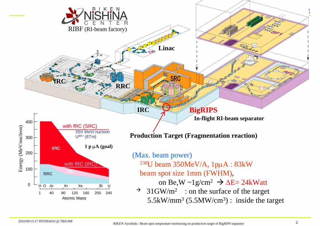
(Max. beam power)238U beam 350MeV/A, 1pμA : 83kWbeam spot size 1mm (FWHM),
on Be,W ~1g/cm2 ΔE= 24kWatt31GW/m2 : on the surface of the target5.5kW/mm3 (5.5MW/cm3) : inside the target
In-flight RI-beam separator
Production Target (Fragmentation reaction)
Linac
RIBF (RI-beam factory)En
ergy
(MeV
/nuc
leon
)
2010/09/13-17 INTDS2010 @ TRIUMFRIKEN Ayoshida : Beam spot temperature monitoring on production target of BigRIPS separator 3
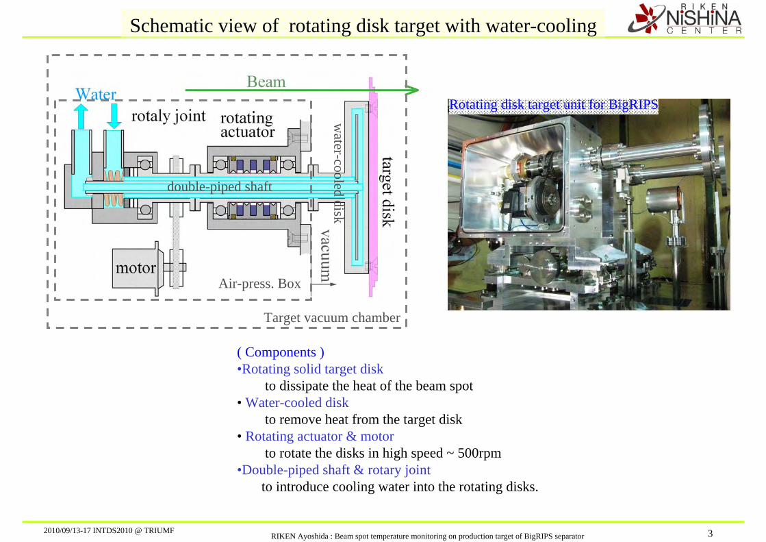
Schematic view of rotating disk target with water-cooling
Rotating disk target unit for BigRIPS
Air-press. Box
Target vacuum chamber
( Components )•Rotating solid target disk
to dissipate the heat of the beam spot• Water-cooled disk
to remove heat from the target disk• Rotating actuator & motor
to rotate the disks in high speed ~ 500rpm•Double-piped shaft & rotary joint
to introduce cooling water into the rotating disks.
double-piped shaft
water-cooled disk
2010/09/13-17 INTDS2010 @ TRIUMFRIKEN Ayoshida : Beam spot temperature monitoring on production target of BigRIPS separator 4
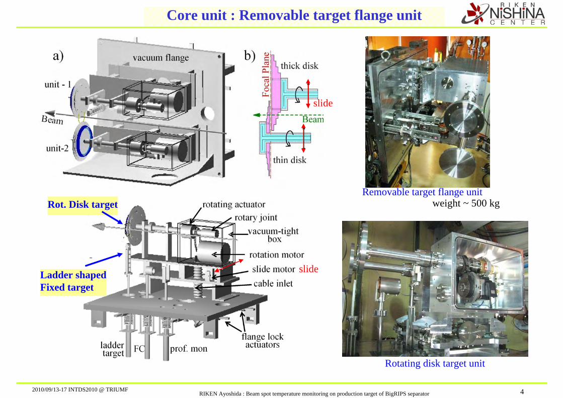
Core unit : Removable target flange unit
Rotating disk target unit
Removable target flange unitweight ~ 500 kg
slide
slide
Rot. Disk target
Ladder shapedFixed target
2010/09/13-17 INTDS2010 @ TRIUMFRIKEN Ayoshida : Beam spot temperature monitoring on production target of BigRIPS separator 5
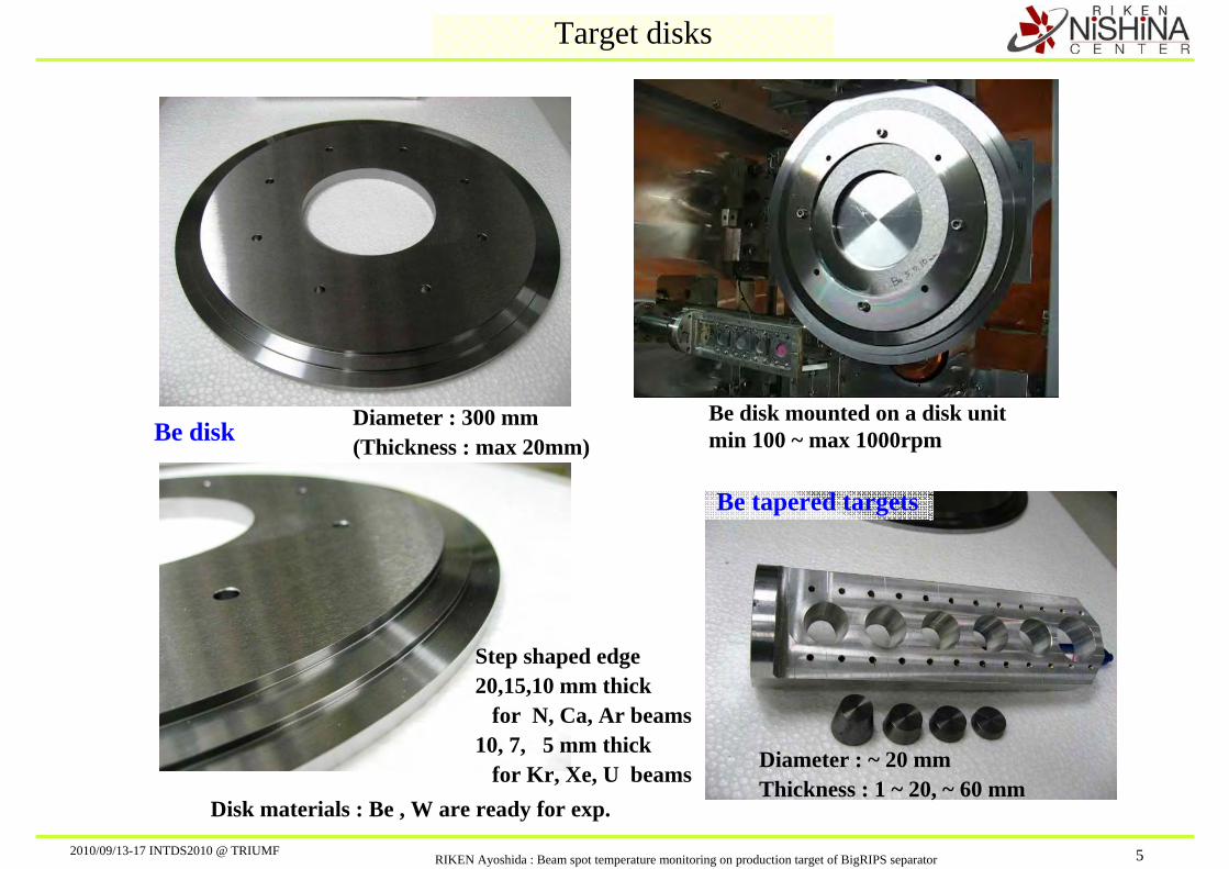
Target disks
Disk materials : Be , W are ready for exp.
Step shaped edge20,15,10 mm thick
for N, Ca, Ar beams 10, 7, 5 mm thick
for Kr, Xe, U beams
Be disk Diameter : 300 mm(Thickness : max 20mm)
Be disk mounted on a disk unitmin 100 ~ max 1000rpm
Be tapered targets
Diameter : ~ 20 mmThickness : 1 ~ 20, ~ 60 mm
2010/09/13-17 INTDS2010 @ TRIUMFRIKEN Ayoshida : Beam spot temperature monitoring on production target of BigRIPS separator 6
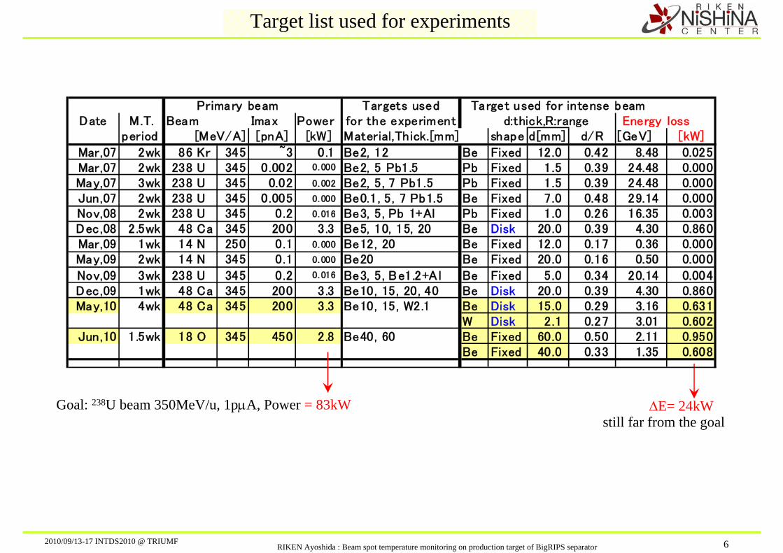
Target list used for experiments
ΔE= 24kWstill far from the goal
Primary beam Targets used Target used for intense beamDate M.T. Beam Imax Power for the experiment d:thick,R:range Energy loss
period [MeV/A] [pnA] [kW] Material,Thick.[mm] shape d[mm] d/R [GeV] [kW]
Mar,07 2wk 86 Kr 345 ~3 0.1 Be2, 12 Be Fixed 12.0 0.42 8.48 0.025Mar,07 2wk 238 U 345 0.002 0.000 Be2, 5 Pb1.5 Pb Fixed 1.5 0.39 24.48 0.000May,07 3wk 238 U 345 0.02 0. 002 Be2, 5, 7 Pb1.5 Pb Fixed 1.5 0.39 24.48 0.000Jun,07 2wk 238 U 345 0.005 0.000 Be0.1, 5, 7 Pb1.5 Be Fixed 7.0 0.48 29.14 0.000Nov,08 2wk 238 U 345 0.2 0. 016 Be3, 5, Pb 1+Al Pb Fixed 1.0 0.26 16.35 0.003Dec,08 2.5wk 48 Ca 345 200 3.3 Be5, 10, 15, 20 Be Disk 20.0 0.39 4.30 0.860Mar,09 1wk 14 N 250 0.1 0. 000 Be12, 20 Be Fixed 12.0 0.17 0.36 0.000May,09 2wk 14 N 345 0.1 0. 000 Be20 Be Fixed 20.0 0.16 0.50 0.000
Nov,09 3wk 238 U 345 0.2 0. 016 Be3, 5, Be1.2+A l Be Fixed 5.0 0.34 20.14 0.004Dec,09 1wk 48 Ca 345 200 3.3 Be10, 15, 20, 40 Be Disk 20.0 0.39 4.30 0.860May,10 4wk 48 Ca 345 200 3.3 Be10, 15, W2.1 Be Disk 15.0 0.29 3.16 0.631
W Disk 2.1 0.27 3.01 0.602Jun,10 1.5wk 18 O 345 450 2.8 Be40, 60 Be Fixed 60.0 0.50 2.11 0.950
Be Fixed 40.0 0.33 1.35 0.608
Goal: 238U beam 350MeV/u, 1pμA, Power = 83kW
2010/09/13-17 INTDS2010 @ TRIUMFRIKEN Ayoshida : Beam spot temperature monitoring on production target of BigRIPS separator 7
Target : BeBeam Spot radi : 0.5mmWater Cool radi : 5.0mm
10
100
1000
10000
0.001 0.01 0.1 1.Primary Beam [puA]
Bea
m S
pot T
emp
[C] U
XeKrArNeOC
Tmp(Be) =1278C
d/R0.80.50.2
Ar
NeO
C
Fixed target
UXe
Kr
31
17
11
6
3
2
[kW/1pμA]
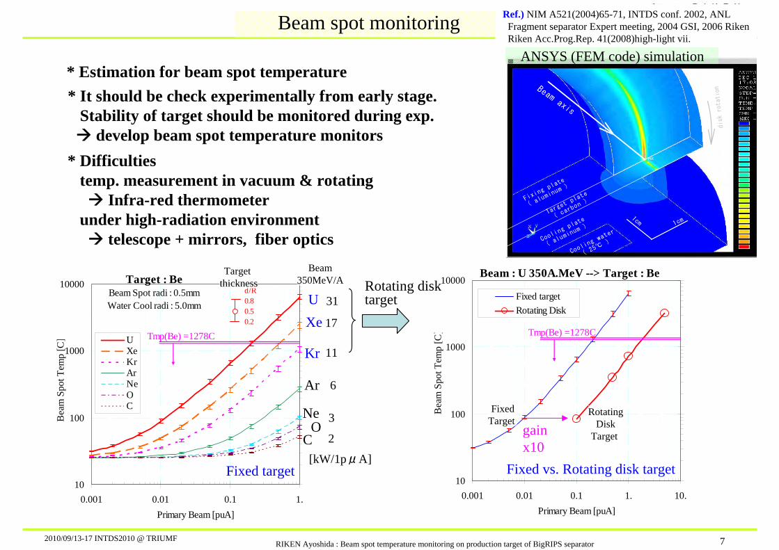
Beam spot monitoring
* Estimation for beam spot temperature
* Difficultiestemp. measurement in vacuum & rotating
Infra-red thermometerunder high-radiation environment
telescope + mirrors, fiber optics
Target thickness
Beam350MeV/A
* It should be check experimentally from early stage.Stability of target should be monitored during exp.
develop beam spot temperature monitors
Beam : U 350A.MeV --> Target : Be
10
100
1000
10000
0.001 0.01 0.1 1. 10.Primary Beam [puA]
Bea
m S
pot T
emp
[C]
Fixed targetRotating Disk
Tmp(Be) =1278C
Fixed vs. Rotating disk target
gain x10
Rotating disktarget
Fixi
ngpl
ate
( alum
inum
)
Coolin
gpla
te
(alu
minum
)
Target
plat
e
(ca
rbon
)
Cooli
ngwa
ter
( 25℃
)
Beamaxis
1cm
1cm
disk
rotation
ANSYS (FEM code) simulation
Ref.) NIM A521(2004)65-71, INTDS conf. 2002, ANLFragment separator Expert meeting, 2004 GSI, 2006 Riken Riken Acc.Prog.Rep. 41(2008)high-light vii.
FixedTarget
RotatingDisk
Target

2010/09/13-17 INTDS2010 @ TRIUMFRIKEN Ayoshida : Beam spot temperature monitoring on production target of BigRIPS separator 8
Target chamber
STQ
1 m
agne
t
Beam
Beam
Unit-2
Unit-1
View portfor
beam spotmonitoring
( Pill
ow se
al )
upperview
sideview
Pump unitAlignment
table
(1) Fiber
(2) CCD
(3) IR, Telescope
(2) (3)(1)
(3)
CCD
CCD

2010/09/13-17 INTDS2010 @ TRIUMFRIKEN Ayoshida : Beam spot temperature monitoring on production target of BigRIPS separator 9
Beam Time : 2010 05/14 – 06/1148Ca20+ 345A.MeV max ~ 300pnA
CCD camera : Radiation damage
5/19 15h 5/21 14h 5/24 10h 5/25 11h05/14 10h Exp. start 5/18 17h
CCD
Beam
CCD
1m
1day 2daystart 3day 7day 10day ~ ~ ~ End : 27day
Primary beam tuning
Secondary beam tuningfor RI beam production
Experiments start
become blind
CCD camera @ port (2)is used for checking
proper motions of targets mechanics
2010/09/13-17 INTDS2010 @ TRIUMFRIKEN Ayoshida : Beam spot temperature monitoring on production target of BigRIPS separator 10
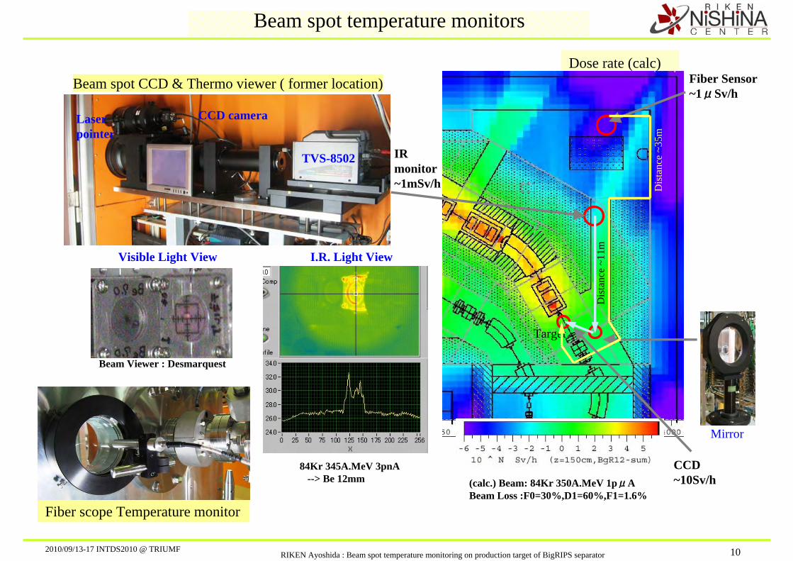
Dose rate (calc)
Beam spot temperature monitors
Target
Mirror
Visible Light View I.R. Light View
84Kr 345A.MeV 3pnA --> Be 12mm
Beam Viewer : Desmarquest
Beam spot CCD & Thermo viewer ( former location)
CCD camera
TVS-8502
Laser pointer
IR monitor~1mSv/h
Dis
tanc
e ~1
1m
Fiber Sensor~1μSv/h
Fiber scope Temperature monitor
Dis
tanc
e ~3
5m
(calc.) Beam: 84Kr 350A.MeV 1pμABeam Loss :F0=30%,D1=60%,F1=1.6%
CCD~10Sv/h
2010/09/13-17 INTDS2010 @ TRIUMFRIKEN Ayoshida : Beam spot temperature monitoring on production target of BigRIPS separator 11
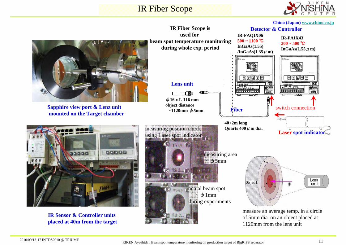
IR Fiber Scope
Lens unit
Detector & Controller
Sapphire view port & Lenz unitmounted on the Target chamber
measure an average temp. in a circle of 5mm dia. on an object placed at 1120mm from the lens unit
Fiber
Chino (Japan) www.chino.co.jp
IR-FAIX43 200 ~ 500 ℃InGaAs(1.55μm)
IR-FAQIX06 500 ~ 1100 ℃InGaAs(1.55)/InGaAs(1.35μm)
φ16 x L 116 mmobject distance
~1120mm φ5mm
40+2m longQuarts 400μm dia.
IR Sensor & Controller unitsplaced at 40m from the target
switch connection
Laser spot indicatormeasuring position checkusing Laser spot indicator
actual beam spot~ φ1mm
during experiments
measuring area~ φ5mm
IR Fiber Scope isused for
beam spot temperature monitoringduring whole exp. period

2010/09/13-17 INTDS2010 @ TRIUMFRIKEN Ayoshida : Beam spot temperature monitoring on production target of BigRIPS separator 12
170
190
210
230
250
270
06/25
18:0
0
06/26
06:0
0
06/26
18:0
0
06/27
06:0
0
06/27
18:0
0
Fib
er
Scope T
em
p. [C
]
18O8+ 345A.MeV Be 60mm (taper shape)Beam spot temperature measured
Beam Current
IR Fiber Scope
IR-FAIX43 ( 200 ~ 500 ℃)
IR-FAQIX06 (500 ~ 1100 ℃)InGaAs(1.55)/InGaAs(1.35μm)
Temp. calibration (ε=1.00)
1.E-02
1.E-01
1.E+00
1.E+01
1.E+02
0 100 200 300 400 500 600 700
Heater [C]
CH
INO
Raw
Data
500
550
600
650
700
750
CH
INO
Tem
p [
C]
Light=OFF 1.35um
Light=OFF 1.55um
Light=ON 1.35um
Light=ON 1.55um
Light=OFF ℃
Light=ON ℃
Room lightON
Room lightOFF
IR sensor output signal (measured)
[ arb
. Uni
t ]
2010/09/13-17 INTDS2010 @ TRIUMFRIKEN Ayoshida : Beam spot temperature monitoring on production target of BigRIPS separator 13
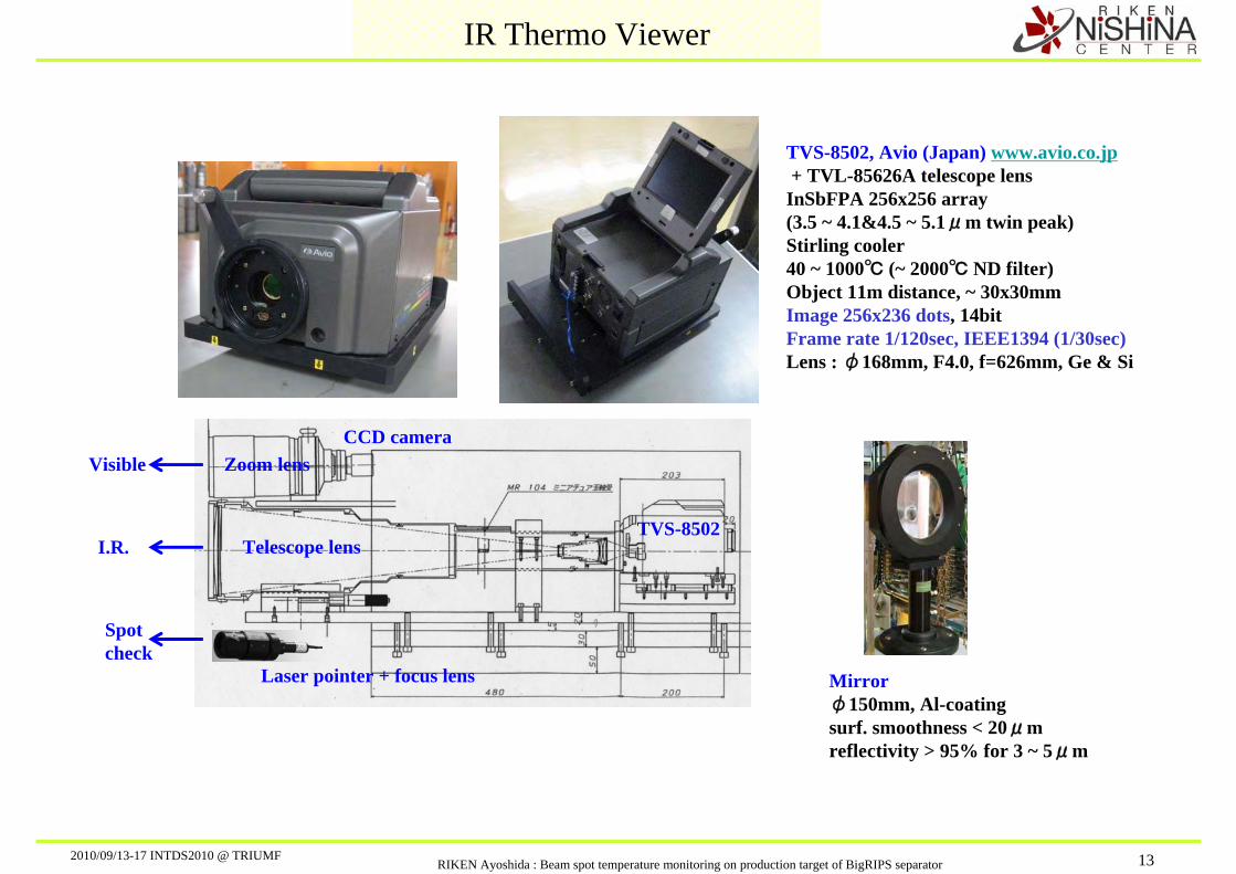
IR Thermo Viewer
TVS-8502, Avio (Japan) www.avio.co.jp+ TVL-85626A telescope lens InSbFPA 256x256 array (3.5 ~ 4.1&4.5 ~ 5.1μm twin peak) Stirling cooler40 ~ 1000℃ (~ 2000℃ ND filter)Object 11m distance, ~ 30x30mmImage 256x236 dots, 14bitFrame rate 1/120sec, IEEE1394 (1/30sec)Lens : φ168mm, F4.0, f=626mm, Ge & Si
Telescope lens
Zoom lensCCD camera
TVS-8502
Laser pointer + focus lens
Visible
I.R.
Spotcheck
Mirrorφ150mm, Al-coatingsurf. smoothness < 20μmreflectivity > 95% for 3 ~ 5μm
2010/09/13-17 INTDS2010 @ TRIUMFRIKEN Ayoshida : Beam spot temperature monitoring on production target of BigRIPS separator 14
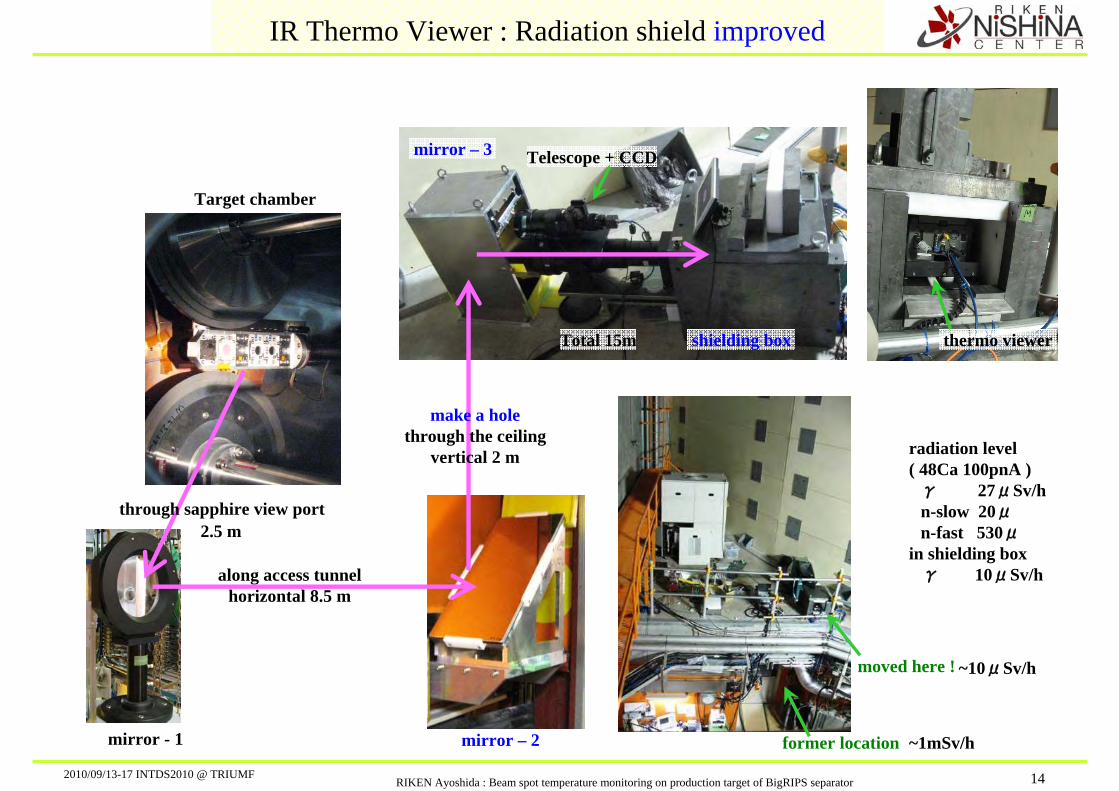
IR Thermo Viewer : Radiation shield improved
Target chamber
mirror - 1
through sapphire view port2.5 m
along access tunnelhorizontal 8.5 m
former location
mirror – 3
shielding box Total 15m
Telescope + CCD
moved here !
mirror – 2
make a holethrough the ceiling
vertical 2 m
thermo viewer
radiation level( 48Ca 100pnA )
γ 27μSv/hn-slow 20μn-fast 530μ
in shielding box γ 10μSv/h
~1mSv/h
~10μSv/h
2010/09/13-17 INTDS2010 @ TRIUMFRIKEN Ayoshida : Beam spot temperature monitoring on production target of BigRIPS separator 15
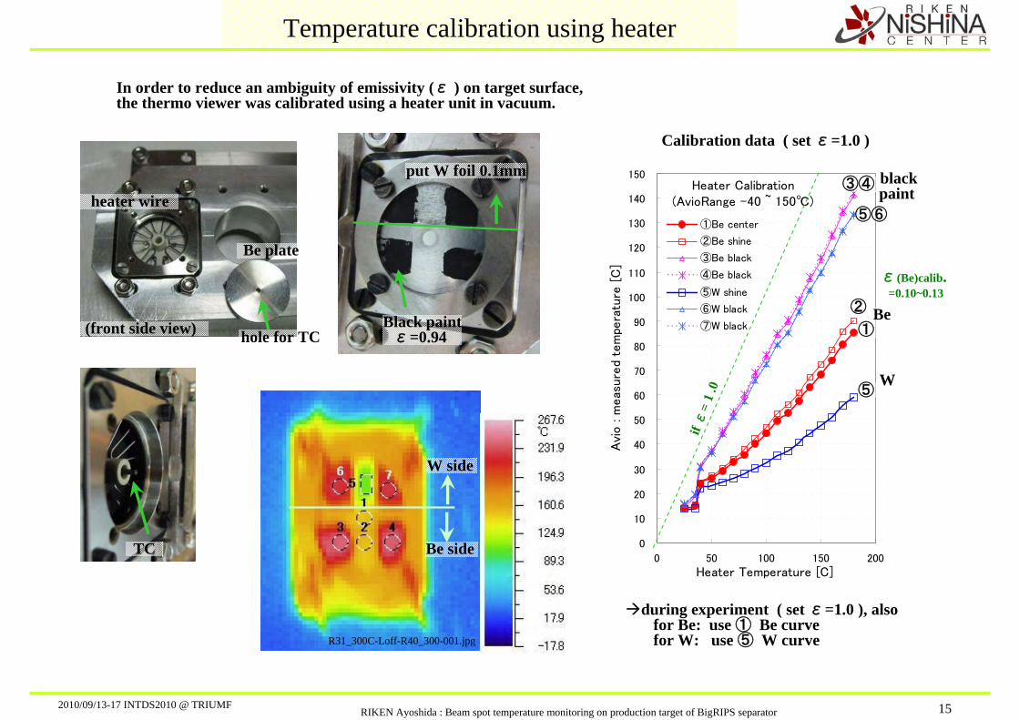
(front side view)
heater wire
Be plate
Temperature calibration using heater
TC
hole for TC
put W foil 0.1mm
Black paintε=0.94
R31_300C-Loff-R40_300-001.jpg
W side
Be side
during experiment ( set ε=1.0 ), alsofor Be: use ① Be curve for W: use ⑤ W curve
Heater Calibration(AvioRange -40 ~ 150℃)
0
10
20
30
40
50
60
70
80
90
100
110
120
130
140
150
0 50 100 150 200
Heater Temperature [C]
Avi
o : m
eas
ure
d te
mpe
ratu
re [
C]
①Be center
②Be shine
③Be black
④Be black
⑤W shine
⑥W black
⑦W black
blackpaint
Be
W
if ε
= 1
.0
Calibration data ( set ε=1.0 )
ε(Be)calib. =0.10~0.13
③④
⑤⑥
②
①
⑤
In order to reduce an ambiguity of emissivity (ε ) on target surface, the thermo viewer was calibrated using a heater unit in vacuum.
2010/09/13-17 INTDS2010 @ TRIUMFRIKEN Ayoshida : Beam spot temperature monitoring on production target of BigRIPS separator 16
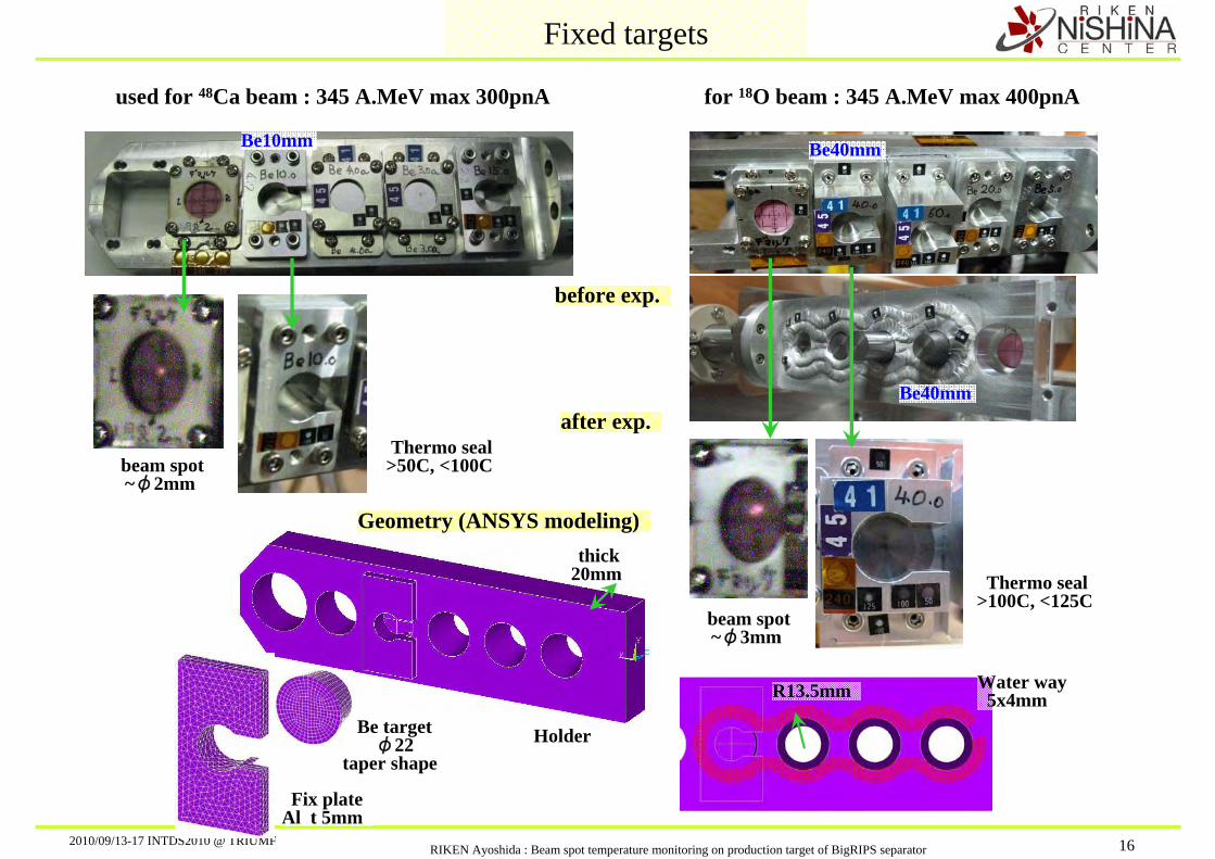
used for 48Ca beam : 345 A.MeV max 300pnA for 18O beam : 345 A.MeV max 400pnA
before exp.
Fixed targets
Be10mm
Be40mm
Be40mm
Water way5x4mm R13.5mm
Holder
thick20mm
Be targetφ22
taper shape
Fix plateAl t 5mm
Geometry (ANSYS modeling)
after exp.
Thermo seal >100C, <125C
Thermo seal >50C, <100C beam spot
~φ2mm
beam spot~φ3mm

2010/09/13-17 INTDS2010 @ TRIUMFRIKEN Ayoshida : Beam spot temperature monitoring on production target of BigRIPS separator 17
℃100.0
90.0
80.0
70.0
60.0
50.0
40.0
30.0
20.0
G1: Beam SpotG2: Al plate
G1
G2
G1
G2
R002_Be40Tp-Rng150c-G01-3500enA-Loff
18O 8+ beam : 345 A.MeV 438pnA (3500enA) Be 40mm thick (taper shape)
G1
G2
Temp.(non-calibrated)
Fixed target ; temperature data magnified view
whole view
18O R002: Be40Tp 438pnA ini_temp=25C
40
60
80
100
120
140
160
180
200
0 50 100 150 200 250
Time [sec]
Beam
Spot
[C
]
BeamSpotBmSpt-ANSYSBmSpt-AnsStaticAlumPlateAlPlt-AnsysAlPlt-AnsStatic
G1:exp
G2:exp
G1: simulation
G2: simulation
Static analysis
Transientanalysis
Thermo Seal : 100~125C
(( ANSYS params ))Convection @ water way = 3kW/(m2.K)
contact @ target taper= 100kW/(m2.K)Water Temp = 25C fix
Therm. Coduct. Be = 180W/(m.K) fixAl = 239W/(m.K) fix
Radiation = offBeam Spot = φ3.0mm fwhm
(( Cooling water data ))Water Flow = 5.4L/min Flow speed = 0.45m/sWater Press = in 0.43 out 0.21 MPaWater Temp = in 25.5C, dT~1.0C = 378WattHeat = dE:1.35GeV*438pnA=591.3Watt
2010/09/13-17 INTDS2010 @ TRIUMFRIKEN Ayoshida : Beam spot temperature monitoring on production target of BigRIPS separator 18
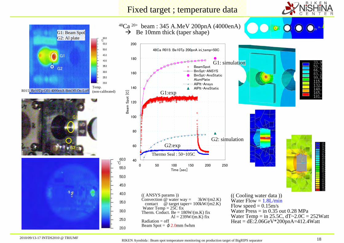
48Ca R015: Be10Tp 200pnA ini_temp=50C
40
60
80
100
120
140
160
180
200
0 50 100 150 200 250Time [sec]
Beam
Spot
[C]
BeamSpotBmSpt-ANSYSBmSpt-AnsStaticAlumPlateAlPlt-AnsysAlPlt-AnsStatic
G1: Beam SpotG2: Al plate
G1
G2
G1
G2
R015_Be10Tp-G01-4000enA-BmOff-On-Loff
48Ca 20+ beam : 345 A.MeV 200pnA (4000enA) Be 10mm thick (taper shape)
G1
G2
Temp.(non-calibrated)
Fixed target ; temperature data
(( ANSYS params ))Convection @ water way = 3kW/(m2.K)
contact @ target taper= 100kW/(m2.K)Water Temp = 25C fix
Therm. Coduct. Be = 180W/(m.K) fixAl = 239W/(m.K) fix
Radiation = offBeam Spot = φ2.0mm fwhm
(( Cooling water data ))Water Flow = 1.8L/min Flow speed = 0.15m/sWater Press = in 0.35 out 0.28 MPaWater Temp = in 25.5C, dT~2.0C = 252WattHeat = dE:2.06GeV*200pnA=412.4Watt
G1:exp
G2:exp
G1: simulation
G2: simulation
Thermo Seal : 50~105C

2010/09/13-17 INTDS2010 @ TRIUMFRIKEN Ayoshida : Beam spot temperature monitoring on production target of BigRIPS separator 19
Beam : 48Ca 345A.MeVTarget : Be 10mm (Taper)
y = 441.00 x + 40.12
0
50
100
150
200
250
0.0 0.1 0.2 0.3 0.4 0.5
I beam [puA]
Beam
Spot
Tem
p. [C
]
ExpC.Trg25C.Wtr25CA.Trg25CA.Wtr25CA.FitA.HtA.Hw,HtE Fit
φ2mm
checkANSYS vs Cyl.Model
Beam : 18O 345A.MeVTarget : Be 40mm (Taper)
y = 291.82 x + 46.35
0
50
100
150
200
250
0.0 0.1 0.2 0.3 0.4 0.5
I beam [puA]
Beam
Spot
Tem
p. [C
]
ExpC.Trg25C.Wtr25CA.Trg25CA.Wtr25CA.FitA.HtA.Hw,HtExpFit
Fixed target data ; compare with simulations
Spot sizeφ3mm
Be 40mm Taper side Thermal contact was good / bad ?
Beam
Qin[W]
Ltg[mm]
r 2[mm] Target Tr2 [℃] Tr1[℃]
r 1[mm]
Tr1 : Beam Spot Temp.= Tr2 + Qin*Ln(r2/r1) /(2πκLtg )
Qin = Ibeam * dE∝ dE / Ltg
(( Cylindrical model ))analytical model
checkANSYS vs Cyl.Model
(( ANSYS model ))3D model
Water way
Be 10mm, simple tapered shape, should correspond well with cylindrical model.
Thermal convection at Water way is too good?
A.Hw,Ht A.FitWater way : Hw = 30k 80k W /(m2.K)Taregt side : Ht = 100k 50k
Thermal contact( thermal convection )10kW/(m2.K) CPU heat-sink
Thermal co
nductivity
= ON
AHtHw = 25Cfix Ht = 100k
Ther
m. c
ond.
= O
N
Discrepancy at the Beam Off temperature Calibration wrong ? or other reasons ?

2010/09/13-17 INTDS2010 @ TRIUMFRIKEN Ayoshida : Beam spot temperature monitoring on production target of BigRIPS separator 20
℃30.0
28.8
27.5
26.3
25.0
23.8
22.5
21.3
20.0
R047: Be15mm Disk 100rpm 3300enA
℃60.0
55.0
50.0
45.0
40.0
35.0
30.0
25.0
20.0
R024: W 2.1mm Disk 150rpm 3700enA
Rotating disk target ; temperature data
48Ca + Be 15 DiskR47 100rpm 165pnA
40
42
44
46
48
50
52
54
0 20 40 60 80 100 120 140 160
Time [sec]
Beam
Spot
[C]
R47_100rpm
min. rotation speed : 100rpm
W disk ; we could observed, but .. Beam spot temperature shows vibration.
ANSYS calculation for disk experimental data has not done yet. ( sorry )
Be disk ; we cold not observe temp. rise.
G1: Beam SpotG1
G148Ca + W2.1DiskR24 150rpm 185pnA
40
60
80
100
120
140
0 50 100 150 200 250
Time [sec]
Beam
Spot
[C]
R24_150rpm
2010/09/13-17 INTDS2010 @ TRIUMFRIKEN Ayoshida : Beam spot temperature monitoring on production target of BigRIPS separator 21
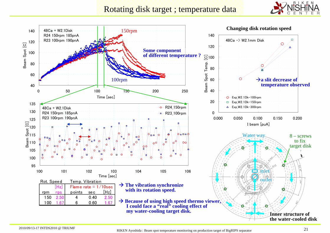
48Ca + W2.1DiskR24 150rpm 185pnAR23 100rpm 190pnA
40
60
80
100
120
140
0 50 100 150 200 250
Time [sec]
Beam
Spot
[C]
Rotating disk target ; temperature data
The vibration synchronizewith its rotation speed.
Some componentof different temperature ?
150rpm
100rpm
Inner structure ofthe water-cooled disk
Water way
inlet
outlet
8 – screwsto fix
target disk
48Ca -> W2.1mm Disk
0
20
40
60
80
100
120
140
0.000 0.050 0.100 0.150 0.200
I beam [puA]
Beam
Spot
Tem
p. [C
]
Exp_W2.1Dk-100rpm
Exp_W2.1Dk-150rpm
Exp_W2.1Dk-300rpm
Changing disk rotation speed
a slit decrease of temperature observed
Because of using high speed thermo viewer,I could face a “real” cooling effect ofmy water-cooling target disk.
48Ca + W2.1DiskR24 150rpm 185pnAR23 100rpm 190pnA
95
100
105
110
115
120
125
130
135
100 101 102 103 104 105 106Time [sec]
Beam
Spot
[C]
R24_150rpm
R23_100rpm
Rot. Speed Temp. Vibration[Hz] Flame rate = 1/10sec
rpm rps points sec [Hz]150 2.50 4 0.40 2.50100 1.67 6 0.60 1.67
2010/09/13-17 INTDS2010 @ TRIUMFRIKEN Ayoshida : Beam spot temperature monitoring on production target of BigRIPS separator 22
Target : WBeam 345MeV/ABeam Spot radi : 1mmWater Cool radi : 13.5mm
10
100
1000
10000
0.001 0.01 0.1 1 10Prim.Beam [puA]
Bea
m S
pot T
emp
[C]
UXeKrCaNeOCU-Disk
d/R0.80.50.2
Tmp(W) =3387C
( Fixed target ) U
Ca
O
Target : BeBeam 345 MeV/ABeam Spot radi : 1mmWater Cool radi : 13.5mm
10
100
1000
10000
0.001 0.01 0.1 1 10Prim.Beam [puA]
Bea
m S
pot T
emp
[C]
UXeKrCaNeOCU-Disk
Tmp(Be) =1278C
d/R0.80.50.2
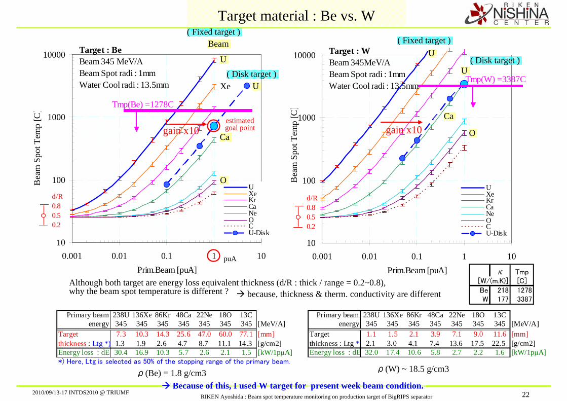
Target material : Be vs. W
Beam
U
Xe
Ca
O
( Fixed target )
gain x10
( Disk target ) U
gain x10
( Disk target ) U
Although both target are energy loss equivalent thickness (d/R : thick / range = 0.2~0.8),why the beam spot temperature is different ?
Primary beam 238U 136Xe 86Kr 48Ca 22Ne 18O 13C energy 345 345 345 345 345 345 345 [MeV/A]
Target 7.3 10.3 14.3 25.6 47.0 60.0 77.1 [mm]thickness : Ltg *) 1.3 1.9 2.6 4.7 8.7 11.1 14.3 [g/cm2]Energy loss : dE 30.4 16.9 10.3 5.7 2.6 2.1 1.5 [kW/1pμA]*) Here, Ltg is selected as 50% of the stopping range of the primary beam.
Primary beam 238U 136Xe 86Kr 48Ca 22Ne 18O 13C energy 345 345 345 345 345 345 345 [MeV/A]
Target 1.1 1.5 2.1 3.9 7.1 9.0 11.6 [mm]thickness : Ltg *) 2.1 3.0 4.1 7.4 13.6 17.5 22.5 [g/cm2]Energy loss : dE 32.0 17.4 10.6 5.8 2.7 2.2 1.6 [kW/1pμA]
κ Tmp[W/(m.K)] [C]
Be 218 1278W 177 3387
ρ(Be) = 1.8 g/cm3 ρ(W) ~ 18.5 g/cm3
because, thickness & therm. conductivity are different
Because of this, I used W target for present week beam condition.
estimated goal point
puA

2010/09/13-17 INTDS2010 @ TRIUMFRIKEN Ayoshida : Beam spot temperature monitoring on production target of BigRIPS separator 23
Target : W
10
100
1000
10000
0.001 0.01 0.1 1. 10. 100.
Heat Density [kW/mm]B
eam
spot
tem
p. [C
].
Target : Be
10
100
1000
10000
0.001 0.01 0.1 1. 10. 100.
Heat Density [kW/mm]
Bea
m sp
ot te
mp.
[C].
Target : Be
10
100
1000
10000
0.01 0.1 1. 10. 100.
Heat Load [kW]
Bea
m sp
ot te
mp.
[C].
Target : W
10
100
1000
10000
0.01 0.1 1. 10. 100.
Heat Load [kW]
Bea
m sp
ot te
mp.
[C].
Target : Be
10
100
1000
10000
0.001 0.01 0.1 1. 10.
Beam intensity [puA]
Bea
m sp
ot te
mp.
[C].
UCaOCa_Exp 10mmO_Exp 40mmU_Disk(ANSYS)
345MeV/A
Target : W
10
100
1000
10000
0.001 0.01 0.1 1. 10.
Beam intensity [puA]
Bea
m sp
ot te
mp.
[C].
U
Ca
O
Ca_Exp 100rpm
Ca_Exp 300rpm
U_Ansys 500rpm
345MeV/A
roadmap
Fix targetdata
Rot.Diskdata
Change X: Heat Load Change X: Heat Density up to1kW
Fixed target on a same line
Although present heat density is1/10 of the goal point,
Both target material data look like following estimation curves.
estimated goal point
Target : Be, W
10
100
1000
10000
0.001 0.01 0.1 1. 10. 100.
Heat Density [kW/mm]
Bea
m sp
ot te
mp.
[C].
Exp. used different target (Be,W),but we can compare them
in the unit of Heat Density.
( Fixed target )
( Disk target )
Be targ.
W targ.
Fixed & Disk target “nearly” on a same line
estimated goal point
(note) κ(Be) 218 ~ κ(W) 177 W/(m.K)
( Fixed target ) U
Ca
O
U ( Disk target )
( Fixed ) U
Ca
O U
( Disk )

2010/09/13-17 INTDS2010 @ TRIUMFRIKEN Ayoshida : Beam spot temperature monitoring on production target of BigRIPS separator 24
Summary
• Beam spot temperature monitoring under high radiation environment is readyFiber scope : for long time monitoring during an experimentThermo viewer : to check & compare temperature distribution with simulations.
•Both data of fixed target and disk target look like following the estimated temperature curve scalded in the unit of energy loss density.
• Although present beam power is less than 1/20 of goal value,beam spot temperature on Be, W target were measured.
( Issues )
• Discrepancy between ANSYS simulation and experimental data still remains.• Beam spot temperature of rotating disk target shows vibration.
Precise analysis should be necessary, in order to estimatethermal conductivity of water way and thermal contact.


