
btob
com
unic
a.co
mM
KTG
-10-
083/
14
Lafert S.p.A. Via J. F. Kennedy, 43 - I-30027 San Donà di Piave (Venezia), Italy
Tel. +39 / 0421 229 611 | Fax +39 / 0421 222 908 | [email protected]
www.lafert.com
CuSTomISeD moTorSThree-PhaSe moTorS
SIngle-PhaSe moTorSBraKe moTorS
TeChnICal CaTalogue 2014
IE3IE2
Te
Ch
nIC
al
Ca
Talo
gu
e 2
01
4 -
Th
ree
-ph
ase
, S
ing
le-p
ha
se,
Bra
ke
mo
tors

TeChnICal CaTalogue mKTg-10-083/14
CUSTOMISED Motors
HIGH PERFORMANCE Motors
SERVO Motors & Drives
ENERGY EFFICIENT Motors
LIFT Motors
Branches & Partners
Lafert GmbH olgastraße 34/1 D - 73728 esslingen - germany Phone +49 / (0) 711 540 3095 + 7 Fax +49 / (0) 711 540 3098 [email protected]
Lafert Electric Motors Ltd. electra house - electra Way Crewe, Cheshire CW1 6glunited Kingdom Phone +44 / (0) 1270 270 022 Fax +44 / (0) 1270 270 [email protected]
Lafert Moteurs S.A.S. l’Isle d’abeau Parc de Chesnes 75, rue de malacombe F - 38070 St. Quentin-Fallavier France Phone +33 / 474 95 41 01 Fax +33 / 474 94 52 28 [email protected]
Lafert Motores Eléctricos, S.L.Polígono Pignatelli, nave 27 e - 50410 Cuarte de huerva (Zaragoza) - SpainPhone +34 / 976 503 822 Fax +34 / 976 504 199 [email protected]
Lafert N.A. (north america)5620 Kennedy road - mississauga ontario l4Z 2a9 - Canada Phone +1 / 800/661 6413 - 905/629 1939Fax +1 / 905/629 2852 [email protected]
Lafert Electric Motors (australia)Factory 3, 117-123 abbott road,hallam - VIC 3803 - australiaPhone +61 / (0)3 95 46 75 15Fax +61 / (0)3 95 47 93 [email protected]
Lafert Singapore Pte Ltd48 hillview Terrace #03-08 hillview Building - Singapore 669269 Phone +65 / 67630400 - 67620400Fax +65 / [email protected]
Lafert (Suzhou) Co., Ltd.no.3 Industrial Plant Building Yue Xi Phase 3,Tian e Dang lu 2011, 15104 Wu Zhongeconomic Development Zone, Suzhou, ChinaPhone +86 / 512 6687 0618Fax +86 / 512 6687 [email protected]

1
General information 3Product range 4StandardS and regulationS 10condition of inStallation 17toleranceS 18Mechanical deSign 19 Degrees of protection Mounting arrangements Materials and painting Bearings Optional features Cooling, vibration and noiseelectrical deSign 28 Rated voltage, frequency and current Insulation and temperature rise Starting rate Thermal protection Connection Encoder order data 34
tHree-PHaSe motorS 37terMinal box 38connection diagraMS 40frequency converter 42 SPare PartS 43tyPe deSignation 44PerforMance data 45 Premium efficiency motors – IE3 High efficiency motors – IE2 Standard efficiency motors – IE1 Two speed motorsdiMenSionS 62
SinGle-PHaSe motorS 73terMinal box 74connection diagraMS 76electronic Starting device 77SPare PartS 78 tyPe deSignation 79PerforMance data 80 Standard motors Motors with starting capacitor Dual voltage motors Dual voltage motors with starting capacitordiMenSionS 84
BraKe motorS 87technical deScriPtion and SPare PartS 88 Motors with high torque DC brake Motors with high torque AC brake Motors with low torque DC brakeconnection diagraMS 94tyPe deSignation 97PerforMance data 98 Standard efficiency motors – IE1 High efficiency motors – IE2diMenSionS 106
CONTENTS


3GENERAL INFORMATION - Technical caTalogue 10-083/14
GENEral iNfOrmaTiON

4 GENERAL INFORMATION - Technical caTalogue 10-083/14
PrODUCT raNGE
miSSion
The Lafert Group, a leading European Motor Company, is committed to continuous growth by being the global leading manufacturer of customised engineered Electric Motors and Drives with specific focus on Industry Automation, Energy Saving, and Renewables.The Lafert Group will strive to be the ideal partner in the Electric Motors and Drives Industry through focus on meeting specific customer demands. Mutually beneficial partnerships are developed by continuous process improvements utilising state-of-the-art products and techniques by a skilled, motivated and professional workforce.
The Lafert Group’s range of products is divided in 5 product sectors:
ENERGY EFFICIENT Motors, Three-phase Motors High Efficiency, IE2 and Premium Efficiency, IE3
CUSTOMISED Motors, Single-phase, Three-phase and Brake motors in special execution
HIGH PERFORMANCE Motors, Permanent Magnet Synchronous Motors and Generators as well as the relevant drives
SERVO Motors & Drives, Brushless Servomotors and Drives for Industrial Automation
LIFT Motors, Permanent Magnet Synchronous Gearless Machines for Elevators
enerGY effiCient motors
CUStomiSeD motors
HiGH PerformanCe motors
SerVo motors & Drives
lift motors

5GENERAL INFORMATION - Technical caTalogue 10-083/14
PrODUCT raNGE
enerGY effiCient motorS
HIGH EFFICIENCY, ENERGY SAVING
The range of Energy Efficient Motors has been developed to meet the increasing demand for increased energy efficiency and energy saving products in Europe, North America and Australia after the introduction of directives imposing higher minimum efficiency levels.
High Efficiency and Premium Efficiency Three-phase Motors up to 200 kW meeting the requirements of IE2 and IE3 internationally efficiency levels in accordance with IEC 60034-30;2008 and test method IEC 60034-2-1;2007.
Motors conforming to the higher efficiency standards for the North American market in accordance with EPAct Regulation (Energy Policy Act, 1992) and EISA Directive (Energy Independence and Security Act, 2007).In addition these motors are verified by UL Underwriters Laboratories Inc..
The range of Energy Efficient Motors from Lafert is the first complete range of IE2 and IE3 motors available to worldwide Industry.
IE3IE2

6 GENERAL INFORMATION - Technical caTalogue 10-083/14
PrODUCT raNGE
CUStomiSeD motorS
CUSTOMISATION, OUR CORE bUSINESS
A wide range of Customised Motors with special execution, in order to optimise electrical and mechanical design for particular markets or specific OEM requests.
Single-phase, Three-phase and Brake Motors manufactured ad hoc for non-standard applications according to customer’s demands: customised flanges and shafts, special electrical design for each duty request, complete tailor-made design, AC or DC brake coil to fit any applications, solutions to special environmental conditions (Smoke and Heat Exhaust Ventilation, Dust Ignition for Zone 22, Non Sparking Exn).

7GENERAL INFORMATION - Technical caTalogue 10-083/14
PrODUCT raNGE
HiGH PerformanCe motorS
SYNCHRONOUS PM IE4 MOTORS: DON’T WAIT FOR THE FUTURE, IT’S HERE NOW!
High Performance (HP) is a generation of PM (Permanent Magnet) Synchronous Motors, achieving IE4 Super Premium Efficiency level, that offer improved electrical efficiency at stable and reduced production costs without applying rare earth magnets.
This uniquely engineered product combines the electrical design of Brushless Servomotors with the mechanical design of AC Induction Motors. The result is a compact motor primarily targeted toward HVAC applications in fans, compressors, and blowers, where there is emphasis on reducing the operating cost or weight and size of the motors.
The complete range 0.37 kW to 30 kW are supplied as stand-alone motors (HPS) to be controlled by a separate drive or as motor/drive integrated units (HPI), specifically designed for their energy saving potential.
Lafert PM Motors’ Awards
A separate catalogue is available.
ADI Index Design 2012: Best Italian design in manufacturing
2014 AHR Expo Innovation Awards: Green Building Category
2013 European New Product Innovation Leadership Award: Electric Motors for HeatingVentilation Air Conditioning (HVAC) Applications by Frost & Sullivan

8 GENERAL INFORMATION - Technical caTalogue 10-083/14
PrODUCT raNGE
SerVo motorS & DriVeS
A MODERN AND COMPLETE RANGE FOR INDUSTRIAL AUTOMATION
The range of brushless Servo Motors is one of the most complete available on the market, with nominal torques 0.20 Nm to 150 Nm. Direct Drive Motors cover torques 10 Nm to 500 Nm.Thanks to its whole integrated manufacturing process, Lafert is one of the few independent manufacturers of servo motors and can supply a wide range of standard and tailor-made products for Industrial Automation giving excellent flexibility and high level of cost efficiency.
The family of Servo Drives is especially engineering for brushless servo motors and DC motors providing particular versatility and adaptability when designing automated industrial machines.These products ensure high reliability and are subjected to strict tests in different loads and climatic conditions.
A separate catalogue is available.

9GENERAL INFORMATION - Technical caTalogue 10-083/14
PrODUCT raNGE
lift motorS
GEARLESS MACHINES FOR ELEVATORS
The Lift range allows the manufacturing of systems where the traction machine is inside the elevator shaft, so there is no need for a machine room, with obvious space and cost savings and a more rational layout of the all components. Permanent Magnet Gearless Synchronous Machines with compact design, reduced energy consumption, low noise level, high comfort and requiring less maintenance. Motors with torque up to 850 Nm for systems with a capacity load up to 1,600 kg, machines with TÜV SÜD Certifications, in compliance with the Specifications UNI EN 81-1:2010 and Lifts Directive 95/16/EC.
A separate catalogue is available.

10 GENERAL INFORMATION - Technical caTalogue 10-083/14
STaNDarDS aND rEGUlaTiONS
QUalitY SYStem CertifiCate
The strictness of our quality control assures the flawless operation and reliability of our products. Our quality is confirmed by the Certificate ISO 9001 awarded by CERMET, a certification body authorized by ACCREDIA.
SafetY StanDarDS
Our motors comply with the requirements of the International Standard IEC 60034 for rotating electrical machines as well as with the following European Directives: Low Voltage Directive (LV) 2006/95/EC, Electromagnetic Compatibility Directive (EMC) 2004/108/EC and RoHS Directive 2011/65/EC on the restriction of hazardous substances in electrical and electronic equipment.
All products comply with the requirements of the Directive Machines (MD) 2006/42/EC. In accordance with this Directive, induction motors are components and intended solely for integration into other machines. Commissioning is forbidden until conformity of the end-product with this Directive is proved.
The CE marking was applied for the first time in 1995.
When operating the motor, the observance of the Regulation EN 60204-1 and safety instructions indicated in our Operating Instructions must be complied with.
Motors complied with many other international standards are available on request:
Motors approved by UL Underwriters Laboratories Inc.
Motors approved by CSA
Motors approved by CQC (small motors up to 1.1 kW – AM, AMBY, AMF series)
effiCienCY StanDarDS
Efficiencies are harmonized to the International Standard IEC 60034-30;2008 that states new efficiency levels: Standard Efficiency IE1, High Efficiency IE2 and Premium Efficiency IE3.The efficiency levels are in accordance with the testing method IEC 60034-2-1;2007.
High Efficiency motors according to EPAct legislation.Verified by UL Underwriters Laboratories Inc.
Premium Efficiency motors according to EISA Directive.Verified by UL Environment.
IE3IE2IE1

11GENERAL INFORMATION - Technical caTalogue 10-083/14
Output Standard Efficiency - IE1 High Efficiency - IE2 Premium Efficiency - IE3
kW 2 poles 4 poles 4 poles 2 poles 4 poles 6 poles 2 poles 4 poles 6 poles
0.75 72.1 72.1 70.0 77.4 79.6 75.9 80.7 82.5 78.91.1 75.0 75.0 72.9 79.6 81.4 78.1 82.7 84.1 81.01.5 77.2 77.2 75.2 81.3 82.8 79.8 84.2 85.3 82.52.2 79.7 79.7 77.7 83.2 84.3 81.8 85.9 86.7 84.33 81.5 81.5 79.7 84.6 85.5 83.3 87.1 87.7 85.64 83.1 83.1 81.4 85.8 86.6 84.6 88.1 88.6 86.8
5.5 84.7 84.7 83.1 87.0 87.7 86.0 89.2 89.6 88.07.5 86.0 86.0 84.7 88.1 88.7 87.2 90.1 90.4 89.111 87.6 87.6 86.4 89.4 89.8 88.7 91.2 91.4 90.315 88.7 88.7 87.7 90.3 90.6 89.7 91.9 92.1 91.2
18.5 89.3 89.3 88.6 90.9 91.2 90.4 92.4 92.6 91.722 89.9 89.9 89.2 91.3 91.6 90.9 92.7 93.0 92.230 90.7 90.7 90.2 92.0 92.3 91.7 93.3 93.6 92.937 91.2 91.2 90.8 92.5 92.7 92.2 93.7 93.9 93.345 91.7 91.7 91.4 92.9 93.1 92.7 94.0 94.2 93.755 92.1 92.1 91.9 93.2 93.5 93.1 94.3 94.6 94.175 92.7 92.7 92.6 93.8 94.0 93.7 94.7 95.0 94.690 93.0 93.0 92.9 94.1 94.2 94.0 95.0 95.2 94.9110 93.3 93.3 93.3 94.3 94.5 94.3 95.2 95.4 95.1132 93.5 93.5 93.5 94.6 94.7 94.6 95.4 95.6 95.4160 93.7 93.8 93.8 94.8 94.9 94.8 95.6 95.8 95.6
200-375 94.0 94.0 94.0 95.0 95.1 95.0 95.8 96.0 95.8
0.75 77.0 78.0 73.0 75.5 82.5 80.0 77.0 85.5 82.51.1 78.5 79.0 75.0 82.5 84.0 85.5 84.0 86.5 87.51.5 81.0 81.5 77.8 84.0 84.0 86.5 85.5 86.5 88.52.2 81.5 83.0 78.5 85.5 87.5 87.5 86.5 89.5 89.53.7 84.5 85.0 83.5 87.5 87.5 87.5 88.5 89.5 89.55.5 86.0 87.0 85.0 88.5 89.5 89.5 89.5 91.7 91.07.5 87.5 87.5 86.0 89.5 89.5 89.5 90.2 91.7 91.011 87.5 88.5 89.0 90.2 91.0 90.2 91.0 92.4 91.715 88.5 89.5 89.5 90.2 91.0 90.2 91.0 93.0 91.7
18.5 89.5 90.5 90.2 91.0 92.4 91.7 91.7 93.6 93.022 89.5 91.0 91.0 91.0 92.4 91.7 91.7 93.6 93.030 90.2 91.7 91.7 91.7 93.0 93.0 92.4 94.1 94.137 91.5 92.4 91.7 92.4 93.0 93.0 93.0 94.5 94.145 91.7 93.0 91.7 93.0 93.6 93.6 93.6 95.0 94.555 92.4 93.0 92.1 93.0 94.1 93.6 93.6 95.4 94.575 93.0 93.2 93.0 93.6 94.5 94.1 94.1 95.4 95.090 93.0 93.2 93.0 94.5 94.5 94.1 95.0 95.4 95.0
110 93.0 93.5 94.1 94.5 95.0 95.0 95.0 95.8 95.8150 94.1 94.5 94.1 95.0 95.0 95.0 95.4 96.2 95.8
185-375 94.1 94.5 94.1 95.4 95.4 95.0 95.8 96.2 95.8
STaNDarDS aND rEGUlaTiONS
new international effiCienCY leVelS for motorS: ie CoDeS
The International standard IEC 60034-30;2008 states the new efficiency levels IE1, IE2 and IE3 for electric motors, ensuring an international common base for motor designing and classification, as well as for national legislative activities.
The efficiency measurement method for motors has also been reviewed.The new standard IEC 60034-2-1;2007 provides for test conditions and efficiency measurement methods which are more accurate and replaces the previous standard EN 60034-2;1996.
The efficiency levels provided for by the standard for single speed, three-phase – brake motors included -50 Hz or 50/60 Hz, motors with rated output between 0.75 kW and 375 kW, 2, 4 or 6 poles, on the basis of continuous duty operation S1 or intermittent periodic duty operation S3 are the following:
• IE1 = Standard Efficiency • IE2 = High Efficiency • IE3 = Premium Efficiency
However, IEC 60034-30 states only the requirements for the efficiency levels, thus creating shared measures worldwide. It does not state the motors to be supplied or the minimum efficiency level. This depends on any regional laws that are applicable.
EFFICIENCY VALUES FOR 50 Hz
ACCORDING TO IEC 60034-30;2008
efficiency standard calculation:
iec 60034-2-1;2007
EFFICIENCY VALUES FOR 60 Hz
ACCORDING TO IEC 60034-30;2008
efficiency standard calculation:
iec 60034-2-1;2007

12 GENERAL INFORMATION - Technical caTalogue 10-083/14
STaNDarDS aND rEGUlaTiONS
Country Product range Law / Regulation Minimum efficiency level Next steps
EUROPE 400 V ± 10%; 50 Hz 0.75 - 375 kW - 2-6 poles
EC 640/2009IEC 30034-30
IE2compulsory 16.06.2011
01.01.2015 - IE3 from 7.5 to 375 kW or IE2 motor with frequency converter 01.01.2017 - IE3 from 0.75 to 375 kW or IE2 motor with frequency converter
RUSSIA up to 690 V ± 10%; 50 Hz 1 - 400 kW - All poles
GOST R 51677-2000 -
SWITZERLAND 400 V ± 10%; 50 Hz 0.75 - 375 kW - 2-6 poles
EnV IE2compulsory 01.07.2011
For extension of regulations in 2015 and 2017, Swiss Energy Act will be revised in time
TURKEY 400 V ± 10%; 50 Hz 0.75 - 375 kW - 2-6 poles
EC 640/2009 IE1 No decision yet. Will follow probably the EU timeline state initiative and customer awareness for IE2
USA 460 V ± 10%; 60 Hz1 - 200 HP - 2-6 poles
Nema EPAct EISA 2007
IE3compulsory 19.12.2010
It is expected that the scope of EISA will be extended in the near future
CANADA 460 V/575 V ± 10%; 60 Hz1 - 200 HP - 2-6 poles
CSA C390-10 IE3compulsory 01.01.2011
As the latest changes were implemented in April 2012, no further changes are expected in the near future
MEXICO 460 V ± 10%; 60 Hz 1 - 200 HP - 2-6 poles
NOM-016-ENER 2010CSA 390
IE2compulsory 01.01.2011
Will follow USA model
BRAZIL 220/380/440/460/480 V ± 10%; 60 Hz 0.75 - 250 kW - 2-8 poles
NBR 17094-1 Regulation 553
IE2compulsory 08.12.2009
It is expected that the scope of regulation will be extended
CHILE 380/400/420/440/460/690 V± 10%; 50 Hz 0.75 Kw - 7.5 kW - 2-6 poles
NCH 3086 IE2compulsory 04.01.2011
CHINA 380 V ± 10%; 50 Hz 0.55 - 315 kW - 2-6 poles
GB 18613-2012 IE2 compulsory 01.07.2011
01.09.2015 - IE3 from 7.5 to 375 kW01.09.2017 - IE3 from 0.75 to 375 kW
HONG KONG 380 V ± 10%; 50 Hz0.75 - 375 kW - 2-6 poles
Mandatary Buildings Energy Efficiency Bill
IE2introduction stage since Dec 2009
01.01.2015 - IE3 from 7.5 to 375 kW or IE2 motor with frequency converter 01.01.2017 - IE3 from 0.75 to 375 kW or IE2 motor with frequency converter
INDIA 415 V/690 V ± 10%; 50 Hz0.37 - 315 kW - 2-8 poles
IS:12615 IE2compulsory 01.06.2011
IE3 from 01.01.2014
ISRAEL 400 V ± 10%; 50 Hz0.75 - 185 kW - 2-8 poles
IS:5289 IE2compulsory 01.02.2008
JAPAN 200/220/400/440 V ± 10%; 50/60 Hz 0.2 - 160 kW - 2-6 poles
JIS C 4210 JIS C 4212
IE2expected
No law, efficiency per JIS standards. IEC 60034-30 will be integrated into JIS in 2012
KOREA up to 600 V ± 10%; 60 Hz0.75 - 200 kW - 2-6 poles
IEC 60034-30 IE2compulsory 01.01.2010
Preliminary:01.01.2015 - IE3 from 37 to 200 kW01.01.2016 - IE3 from 15 to 37 kW01.01.2017 - IE3 from 0.75 to 15 kW
SINGAPORE 415 V ± 10%; 50 Hz1.1 - 90 kW - 2-4 poles
SS530:2006 IE2 Only government projects compulsory IE2
TAIWAN < 600 V ± 10%; 60 Hz0.37 - 200 kW - 2-8 poles
CNS14400 IE2 No plan to adapt IEC 60034-30. IE2 motors can be certified acc. to CNS 14400 as high efficiency motors
SAUDI ARABIA 380 V/ 460 V ± 5%; 60 Hzall kW - all poles
No regulation -
UNITED ARAB EMIRATES
400 V ± 10%; 50 Hz0.75 - 375 kW - 2-6 poles
No regulation IE1 No regional standards regarding a minimun efficiency
SOUTH AFRICA 400 V/525 V ± 10%;50 Hz 0.75 - 375 kW - 2-6 poles
IEC 60034-30 IE1
AUSTRALIANEW ZEALAND
415 V/690 V ± 10%; 50 Hz0.75 - 186 kW - 2-8 poles
AS/NZS 1359.5-2004 IE2compulsory 01.04.2006
IE3 expected for near future
GloBallY minimUm effiCienCY StanDarDS

13GENERAL INFORMATION - Technical caTalogue 10-083/14
STaNDarDS aND rEGUlaTiONS
eU – CommiSSion reGUlation eC 640/2009
The EcoDesign ErP Directive (2009/125/CE) states the ecodesign requirements for energy-using products. The Commission Regulation EC 640/2009 specifies efficiency requirements for electric motors and introduces in all countries of the European Community the obligation of the IE2 minimum efficiency level from June 2011.
The IE class must be marked on the rating plate, but it is not necessary to register products.Market surveillance is the responsibility of the individual member states.
At further dates, progressively higher minimum efficiency requirements will be established.The IE3 level will come in from 2015-2017.
Motors to be exclusively exported out of the EU (machine distributors or manufacturers) may be produced and distributed with IE1 efficiency level even after 16th June 2011. To that end, a statement will have to be made to the manufacturer.
USa – eiSa 2007
The Energy Independence and Security Act of 2007 (EISA) was signed into law on Dec 2007 and enforced in Dec 2010.EISA replaces the previous EPAct (Energy Policy Act 1992) approved by the U.S. Congress in 1992, and sets Nema Super Premium Efficiency IE3 as minimum level for general purpose, three-phase AC industrial motors from 1 to 500HP which are manufactured or imported for sale in USA.
The U.S. Department of Energy (DOE) is responsible for establishing the rules to implement. The rating plate must be market with the motor’s nominal full load efficiency (NEMA nominal efficiency) and the manufacturer’s CC-number (compliance certificate number).
Regulation-Standard EC 640/2009IEC 60034-30
Testing Method IEC 60034-2-1:2007 (now amended)
Product Range
•Three-phase squirrel cage asynchronous motors: 0.75 kW - 375 kW, 2,4 and 6 poles•Continuous duty S1 •Up to 1000 V•50 Hz or 50/60 Hz
Minimum Efficiency Since June 2011Energy Efficient (IE2)
Exclusions •Brake Motors•Motors for explosive atmospheres
Future IE3 from 1.1.2015 > 7.5-375 kW or IE2+inverterIE3 from 1.1.2017 > 0.75-375 kW or IE2+inverter
Regulation-Standard Epact 2007 EISA (NEMA-MG-1)
Testing Method IEEE 112-B or CSA390-10
Product Range
•Subtype I - General Purpose Motors: 1HP-200HP, 2 to 6 poles•Subtype II - General purpose motors (Subtype I) Configured: U frame, Design C, close
coupled pump, footless, vertical solid Shaft normal thrust (horizontal) and fire pumps : 1HP to 200HP (0.75kW-150kW) 2 to 8 poles
•General Purpose - 201HP-500HP, 2 to 8 poles, Up to 600V 60Hz
Minimum Efficiency
Since 19.12.2010NEMA Premium (IE3) - Subtype I Energy Efficient ( IE2) - Subtype IIEnergy Efficient (IE2) - General Purpose
Exclusions
•IEC frame size < 90 and 100•Not line started motors•Customized OEM mounting•Intermittent duty•Brake Motors with integral brake design (not removable)•TENV and TEAO enclosures•Hollow shaft motors•201HP to 500HP design A
Future It is expected that the scope of EISA will be extended in the near future

14 GENERAL INFORMATION - Technical caTalogue 10-083/14
Regulation-Standard EEA C390-10 (Nema-MG-1)
Testing Method CSA C390-10
Product Range
•Subtype I: NEMA T frame or IEC frame designation 90 or above, NEMA design A or B or IEC design N, Standard shaft , R-shaft or S-shaft or an IEC equivalent: 1HP-200HP (0.75kW-150kW) 2 to 6 poles
•Subtype II: NEMA U frame or equivalent IEC dimensions, NEMA design C, or IEC design H, close coupled pump, vertically-mounted solid shaft normal thrust(as tested in the horizontal position), footless:1HP-500HP (0.75kW-375kW), 2 to 8 poles
•General Purpose: NEMA design B:200HP-500HP, 2 to 8 poles, IEC design N: 150kW-375kW, 2 to 8 poles Up to 600V 60Hz or 50/60Hz
Minimum EfficiencySince 12.04.2012 NEMA Premium (IE3): Subtype IEnergy Efficient (IE2): Subtype II and General Purpose
Exclusions •Inverter duty motors•IEC frame size 80 and below
Future No further changes to the regulations are expected in the near future
CanaDa - enerGY effiCienCY aCt
Canada has had minimum energy performance standards in place since 1995. These standards were amended in 1997 to include Explosion Proof Motors and Integral Gear Assembly Motors.
The regulation regarding electric motors was again revised and, as of January 2010, have a more stringent scope and the minimum efficiency levels are either IE3 and IE2 depending on the output power or mounting position.
The rating plate must show NEMA nominal efficiency at 100% load and the safety certificate marking, such us CSA.
aUStralia – mePS SCHeme
The Australian MEPS Scheme was announced in 2001 by the Australian Greenhouse Office (AGO), and was revised in 2006. All motors covered by the scheme that will be sold in the Australian and New Zealand markets must be registered in a National online database system, www.energyrating.gov.au/appsearch/motors.asp.
Standards AS/NZS 1359,5:2004 stipulates two efficiency levels: the compulsory minimum efficiency level IE2 or better, and a voluntary high efficiency level IE3 or better. The scheme is monitored by a regulatory body which conducts random testing to ensure compliance. Importing unregistered motors is subject to strict penalties.
Regulation-Standard AS/NZS 1359,5:2004
Testing Method Method A (equivalent to IEC60034-2-1:2007 and IEEE112-B) or Method B (equivalent to the old IEC 60034-2)
Product Range •The phase electric motors: 0.73kW -185kW, 2 to 8 poles, Up to 1100V 50Hz
Minimum Efficiency Since 2001 (2002 in New Zealand), revision in both countries 2006Energy Efficient (IE2)
Exclusions
•Submersible motors•Integral geared motor systems•Variable or multispeed motors•Motors rated for short duty cycles
Future Discussion are on going about changing limits to match IEC 60034-30 efficiency classes and making IE3 compulsory
STaNDarDS aND rEGUlaTiONS

15GENERAL INFORMATION - Technical caTalogue 10-083/14
CHina – enerGY laBel SCHeme
The China Energy Label Scheme has been mandatory since 01.09.2008 and was revised in 2012. From 01.09.2012 motors must meet Grade 3 (IE2) requirements. China has taken a major step towards harmonizing its national standards with IEC standards.
Standard GB/T1032 defining the efficiency measuring method, has been updated and brought in line with IEC 60034-2-1 and the grades are in line with efficiency classes defined in IEC 60034-30.
In addition to energy efficiency requirements, low power motors are subject to CCC certification.
Regulation-Standard 553/NBR17094-1
Testing Method NBR17094
Product Range•Electric Motors, single speed for continuous duty IEC design N or Nema Design
A,B or C, TEFC and Exn 0.75kW-185kW, 2&4 poles; 0.75kW-150kW 6 poles; 0.75kW-110kW 8 poles, Up to 600V 60Hz
Minimum EfficiencyMEPS since Dec 2009Since 2012 Energy Efficient (IE2)
Exclusions
•Servo Motors•Permanent Magnet Motors•IP23•S2 to S10 according to NBR 7094.2003•Exd(e), EX(e), DIP
Future Include - Voltages up to 1000V - IP23 -S3 (>80%) - Non Ventilated Motors
Regulation-Standard GB 25958/GB 18613-2012
Testing Method IEC 60034-2-1, efficiency grades in line with IEC 60034-30 (IE2,IE3)
Product Range •Three phase electric induction motors, design N, TEFC 0.55kW to 315kW 2 to 6 poles, Up to 1000V 50Hz
Minimum Efficiency Since 01.07.2011 Energy Efficient (IE2)
Exclusions
•Marine motors•Brake motors•Motors completely integrated into a machine•Motors with electro-magnetic braking incorporated•Motors with a duty type other than S1, or S3 with cyclic factor of 80% or higher•Multispeed motors•Inverter fed motors
Future IE3 from 01.09.2015: 7.5kW-375kWIE3 from 01.09.2017: 0.75kW-375kW
BraZil – PBe laBelinG ProGram
The PbE brazilian Labeling Program has been in force since December 2009 and is overseen by INMETRO. From 2012 the minimum efficiency level is IE2.All motors covered by NBR standards must be provided with specific rating plate marking and additional stickers depending on a degree of protection.
All motors must be registered on the INMETRO, website at www.inmetro.gov.br.
STaNDarDS aND rEGUlaTiONS

16 GENERAL INFORMATION - Technical caTalogue 10-083/14
Korea – mePS SCHeme
The Korean MEPS Scheme was introduced on 1.7.2008 by the Ministry of Commerce, Industry and Energy (MOCIE) and implemented in three steps. Certification is granted by the Korea Energy Management Corporation (KEMCO).
Korean MEPS is identical to IE2 (60HZ). A specific sticker is required and all motors must be registered with the authorities. Motors that do not have the MEPS sticker will not be allowed into Korea.
Regulation-Standard IEC 60034-30
Testing Method IEC60034-2-1 or IEEE112-B
Product Range•Three phase induction motor, single speed, foot or flange design A or B
0.75kW-200kW (2,4 poles); 0.75kW-160kW (6 poles) 0.75kW-110kW (8 poles) Up to 600V 60Hz
Minimum Efficiency Since 2008Energy Effecient (IE2)
Exclusions•TENV motors•Air over motors•Permanent Magnet motors
Future
Preliminary plans:IE3 from 01.01.2015: 37kW-200kWIE3 from 01.01.2016: 15kW-37kWIE3 from 01.01.2017: 0.75kW-15kW
reSt of tHe worlD
Many Countries are recognizing the importance of Energy Efficiency in electric motors and its potential economic and environmental impact and are working on developing mandatory minimum energy performance standards to be implemented in the near future.These standards are expected to follow the IEC60034-30 classification.
STaNDarDS aND rEGUlaTiONS

17GENERAL INFORMATION - Technical caTalogue 10-083/14
MEC
HA
NIC
AL
Rating and performance IEC 60034-1
Methods for determining losses and efficiency using tests IEC 60034-2
Standard method for determing losses and efficiency from tests IEC 60034-2-1
Efficiency classes of single speed, three-phase, cage-induction motors (IE-code) IEC 60034-30
Terminal markings and direction of rotation IEC 60034-8
Starting performance IEC 60034-12
Standard voltages IEC 60038
Insulating materials IEC 60085
Dimensions and output ratings IEC 60072
Mounting dimensions and relationship frame sizes-output ratings, IM B3, IM B5, IM B14 IEC 60072
Cylindrical shaft ends for electric motors IEC 60072
Degrees of protection IEC 60034-5
Methods of cooling IEC 60034-6
Mounting arrangements IEC 60034-7
Noise limits IEC 60034-9
Mechanical vibration IEC 60034-14
Mounting flanges DIN 42948
Tolerances of mounting and shaft extensions DIN 42955
Classification of environmental conditions IEC 60721-2-1
Mechanical vibration; balancing ISO 8821
The motors comply with the relevant standards and regulations, especially:
ELEC
TRIC
AL
The motors are designed for operation at altitudes ≤ 1000 m above sea-level and at ambient temperatures of up to 40° C. Exceptions are indicated on the rating plate.The motors conform to degree of protection IP 55 to IEC 60034-51). Higher protection on request.
The standard design for horizontal mounting is suitable for indoor and protected outdoor installation, climate group moderate (see page 18) (temperature of coolant -20° to +40° C).For unprotected outdoor installation or severe climatic conditions (moisture category wet, climate group worldwide, extremely dusty site conditions, aggressive industrial atmosphere, danger of storm rain and coastal climate, danger of attack by termites, etc.), as well as vertical mounting, special protective measures are recommended, such as:
• Protective cowl (for vertical shaft-down motors)• For vertical shaft-up motors additional bearing seal and flange drainage• Special paint finish• Treatment of winding with protective moisture-proof varnish• Anti-condensation heating (possibly winding heating)• Condensation drain holes
The special measures to be applied have to be agreed with the factory once the conditions of installation have been settled.
The corresponding conditions of installation have to be clearly indicated in the order.
1) IP54 for brake motors AMS and for AMBZ, AMBY from size 63 to 132
CONDiTiONS Of iNSTallaTiON

18 GENERAL INFORMATION - Technical caTalogue 10-083/14
meCHaniCal toleranCeS
According to IEC 60072-1, the following tolerances on mechanical dimensions of electric motors are permitted:
Parameter Code Tolerance
Shaft height H - up to 250 -0.5 mm - over 250 -1 mm
- from 11 to 28 mm j6Diameter of shaft end1) D-DA - from 38 to 48 mm k6 - from 55 to 100 mm m6
Hub key width F-FA h9
Flange spigot N - up to 132 j6 - over size 132 h6
1) Centering holes in shaft extension to DIN 332 part 2
eleCtriCal toleranCeS
For industrial motors to EN 60034-1, certain tolerances must be allowed on guaranteed values, taking into consideration the necessary tolerances for the manufacture of such motors and the materials used. The standard includes the following remarks:
1- It is not intended that guarantees necessarily have to be given for all or any of the items involved. Quotations including guaranteed values subject to tolerances should say so, and the tolerances should be in accordance with the table.2- Attention is drawn to the different interpretation of the term guarantee. In some countries a distinction is made between guaranteed values and typical or declared values. 3- Where a tolerance is stated in only one direction, the value is not limited in the other direction.
Values for Tolerance
Efficiency (η) - 0.15 (1 - η) at PN ≤ 150 kW(by indirect determination) - 0.1 (1 - η) at PN > 150 kW
Power factor (cos ϕ) 1 - cos ϕ
, minimum 0.02, maximum 0.07
Slip (s) ± 20 % of the guaranteed slip at PN ≥ 1 kW(at rated load and at working temperature) ± 30 % of the guaranteed slip at PN < 1 kW
breakaway starting current (IA) + 20 % of the guaranteed starting current(in the starting circuit envisaged) (no lower limit)
breakaway torque (MA) - 15 % and + 25 % of the guaranteed breakaway torque (+ 25 % may be exceeded by agreement)
Pull-up torque (MS) - 15 % of the guaranteed value
Pull-out torque (MK) - 10 % of the guaranteed value (after allowing for this tolerance, MK /MN not less than 1.6)
Moment of inertia (J) ± 10 % of the guaranteed value
6
TOlEraNCES

19GENERAL INFORMATION - Technical caTalogue 10-083/14
mECHaNiCal DESiGN
DeGreeS of ProteCtion
Degrees of mechanical protection for machines are designated in accordance with IEC 60034-5 by the letters IP and two characteristic numerals.
IP Description
0 No special protection 1 Protection against solid foreign bodies larger than 50 mm (Example: inadvertent contact with the hand)
2 Protection against solid foreign bodies larger than 12 mm (Example: inadvertent contact with the fingers)
3 Protection against solid foreign bodies larger than 2.5 mm (Example: Wires, tools)
4 Protection against solid foreign bodies larger than 1 mm (Example: Wires, bands)
5 Protection against dust (harmful deposits of dust)
6 Complete protection against dust
IP Description
0 No special protection
1 Protection against vertically falling water drops (condensation)
2 Protection against dropping water when inclined by up to 15°
3 Protection against waterspray at up to 60° from vertical
4 Protection against water splashed from any direction
5 Protection against water projected by a nozzle from any direction
6 Protection against heavy seas or water projected in powerful jets
7 Protection when submerged between 0.15 and 1 m.
8 Protection when continuously submerged in water at conditions agreed between the manufacturer and the user
Second numeral:Protection against ingress of water
First numeral: Protection against contact and ingress of foreign bodies

20 GENERAL INFORMATION - Technical caTalogue 10-083/14
It is essential to state the desired mounting arrangement when ordering, as the constructive design depends partly on the mounting arrangement.
mECHaNiCal DESiGN
moUntinG arranGementS
Mounting arrangements for rotating electrical machines are designated according to IEC 60034-7, Code I (in brackets Code II).
Frame Size b3 b5 b35 based on b5 based on b3 based on b35
V1 V3 V5 V6 b6 b7 b8 V15 V36
56-160 √ √ √ √ √ √ √ √ √ √ √ √
180-225 √ √ √ √ * * * * * * * *
250-315 √ * √ * * * * * * * * *
* for high loads refer to us
Foot mounting Flange mounting Motors without endshield
IM b34 (IM 2101)Flange type C toDIN 42 948 at drive end
IM V6 (IM 1031)
IM V5 (IM 1011)
IM b8 (IM 1071)
IM b7 (IM 1061)
IM b6 (IM 1051)
IM b3 (IM 1001)
IM V19 (IM 3631)Flange type C toDIN 42 948 at drive end
IM V18 (IM 3611)Flange type C toDIN 42 948 at drive end
IM b14 (IM 3601)Flange type C toDIN 42 948 at drive end
IM b35 (IM 2001)Flange type A toDIN 42 948 at drive end
IM V3 (IM 3031)Flange type A toDIN 42 948 at drive end
IM V1 (IM 3011)Flange type A toDIN 42 948 at drive end
IM b5 (IM 3001)Flange type A toDIN 42 948 atdrive end
IM b15 (IM 1201)without endshield and withoutball bearings on drive end
IM V9 (IM 9131)without endshield and withoutball bearings on drive end
IM V8 (IM 9111)without endshield and withoutball bearings on drive end
IM b9 (IM 9101)without endshield and withoutball bearings on drive end
All standard motors can be installed according to the following mounting arrangements:

21GENERAL INFORMATION - Technical caTalogue 10-083/14
mECHaNiCal DESiGN
materialS
Paint finiSH
NORMAL FINISH
Suitable for climate group Moderate to IEC 60721-2-1, e.g. indoor and outdoor installation.For short periods: up to 100% rel. humidity at temperatures up to +30° C. Continuously: up to 85% rel. humidity at temperatures up to +25° C.Standard paint color: RAL 9005.
SPECIAL FINISH K1
Suitable for climate group Worldwide to IEC 60721-2-1, e.g. outdoor installation in corrosive chemical and marine atmospheres.For short periods: up to 100% rel. humidity at temperatures up to +35° C.Continuously: up to 98% rel. humidity at temperatures up to +30° C.
Motor parts Frame size Material
Motor housing 56 - 160 Aluminium alloy 180 - 315 Cast iron
Endshield 56 - 160 Aluminium alloy* 180 - 315 Cast iron Flanged endshield 56 - 160 Aluminium alloy* 180 - 315 Cast iron Fan cover 56 - 112 Plastics 56 - 112 Sheet steel (optional) 1)
132 - 315 Sheet steel Fan 56 - 315 Plastics 56 - 160 Aluminium alloy (optional) Terminal box 56 - 112 Plastics 56 - 112 Aluminium alloy (optional) 2)
132 - 160 Aluminium alloy 180 - 315 Cast iron
1) Standard for brake motors type AMBY and AMBZ and for AMS 1122) For three-phase motors only
* Cast iron option for 112-132

22 GENERAL INFORMATION - Technical caTalogue 10-083/14
BearinGS
CLASSIFICATION OF bEARINGS (STANDARD DESIGN) 1)
Bearings for standard design have permanent lubrication. Ball bearings to ISO15 (DIN 625).
Frame size Poles DE - NDE Dimension 56 2 + 4 6201-2Z 12x32x10 63 2 + 4 6202-2Z 15x35x11 71 2 - 8 6203-2Z 17x40x12 80 2 - 8 6204-2Z C3 20x47x14 90 2 - 8 6205-2Z C3 25x52x15 100 2 - 8 6206-2Z C3 30x62x16 112 2 - 8 6306-2Z C3 30x72x19 132 2 - 8 6208-2Z C3 40x80x18 160 2 - 8 6309-2Z C3 45x100x25 180 2 - 8 6311 C3 55x120x29 200 2 - 8 6312 C3 60x130x31 225 2 - 8 6313 C3 65x140x33 250 2 - 8 6314 C3 70x150x35 280 2 - 8 6316 C3 80x170x39 315 2 6317 C3 85x180x41 315 4 - 8 NU319 C3 - 6319 C3 95x200x45
1) With regard on bearings for special design, consult us
mECHaNiCal DESiGN
Frame size bearing DE bearing NDE Spring-loaded
56 - 160 Standard motors Non-locating bearing Non-locating bearing Non-drive end 63 - 160 brake motors Non-locating bearing Locating bearing Drive end180 - 315 Standard motors Locating bearing Non-locating bearing Non-drive end
bEARING ARRANGEMENT
LUbRICATION
Permanent lubrication up to 160 frame180 frame up with regreasing facility lubrication nipple is a flat M10x1 to DIN 3404
ROLLER bEARINGS
Roller bearings available as an option. Please consult us.
RELUbRICATION INTERVALS
Relubrication intervals for operating temperatures up to 70° C for 1000 hours
3000 RPM 1500 RPM 1000 RPM Quantity
Frame Size Horizontal Vertical Horizontal Vertical Horizontal Vertical gr
180 4.00 2.00 9.00 4.50 13.00 7.50 15200 3.50 1.75 8.00 4.00 12.00 6.00 20225 3.00 1.50 7.50 3.75 11.00 5.50 23250 2.00 1.00 7.00 3.50 10.00 5.00 26280 1.50 0.75 6.50 3.25 9.00 4.50 40315 1.00 0.50 4.00 2.00 8.00 4.00 55

23GENERAL INFORMATION - Technical caTalogue 10-083/14
mECHaNiCal DESiGN
Belt DriVe
The data apply only to the normal drive end shaft extension of IM B3 motors with one speed.Calculation of belt drive:
19120 · P · kFR = D1 · n
FR = Radial shaft load in N P = Output in kW n = Speed in min-1
D1 = Pulley diameter in m k = Belt tension factor, varying with the type of belt, assumed to be approximately: 3-4 for normal flat belt without idler pulley 2-2.5 for normal flat belt with idler pulley 2.2-2.5 for V-belt For exact data apply to the belt manufacturer.
PermiSSiBle axial forCeS
Maximum permissible axial forces without additional radial forces*
Frame Horizontal shaft Vertical shaft - force upwards Vertical shaft - force downwards size 3000 1500 1000 750 3000 1500 1000 750 3000 1500 1000 750 min -1 min -1 min -1 min -1 min -1 min -1 min -1 min -1 min -1 min -1 min -1 min -1
kN kN kN kN kN kN kN kN kN kN kN kN 56 0.16 0.21 - - 0.18 0.22 - - 0.15 0.19 - - 63 0.19 0.26 - - 0.21 0.28 - - 0.17 0.24 - - 71 0.23 0.33 0.33 0.37 0.26 0.35 0.36 0.39 0.21 0.30 0.31 0.34 80 0.32 0.44 0.46 0.50 0.34 0.47 0.48 0.53 0.29 0.41 0.43 0.47 90 0.34 0.48 0.49 0.54 0.38 0.47 0.53 0.58 0.31 0.44 0.46 0.51 100 0.48 0.68 0.70 0.77 0.54 0.74 0.76 0.83 0.43 0.62 0.64 0.71 112 0.48 0.68 0.70 0.77 0.56 0.75 0.77 0.84 0.40 0.60 0.62 0.69 132 S 0.80 1.13 1.16 1.28 1.00 1.32 1.36 1.47 0.61 0.93 0.97 1.08 132 M 0.78 1.09 1.13 1.24 0.99 1.30 1.33 1.45 0.58 0.89 0.92 1.03 160 M 0.84 1.18 1.21 1.33 1.18 1.52 1.56 1.68 0.50 0.83 0.87 0.99 160 L 0.82 1.15 1.18 1.30 1.18 1.51 1.55 1.67 0.46 0.79 0.82 0.94 180 0.82 1.15 1.18 1.30 1.18 1.51 1.55 1.67 0.46 0.79 0.82 0.94 200 0.82 1.15 1.18 1.30 1.18 1.51 1.55 1.67 0.46 0.79 0.82 0.94 225 1.10 1.60 1.90 2.40 2.10 2.60 2.90 3.40 0.30 0.70 1.00 1.50 250 1.00 1.60 2.00 2.50 2.30 2.70 3.20 3.70 0.20 0.60 1.10 1.50 280 1.70 1.90 2.40 2.90 2.90 3.10 3.60 3.70 0.15 0.30 0.80 1.00 315 2.00 14.00 14.00 14.00 3.60 8.00 9.20 7.40 1.00 1.90 2.40 2.90
Values for 50 Hz. For service on 60 Hz, reduce values by 10%
* Consult according to direction of force

24 GENERAL INFORMATION - Technical caTalogue 10-083/14
mECHaNiCal DESiGN
Frame 3000 1500 1000 750 size min -1 min -1 min -1 min -1
kN kN kN kN
56 0.34 0.42 - - 63 0.38 0.48 - - 71 0.46 0.58 0.67 0.73 80 0.59 0.83 0.86 0.94 90 0.67 0.94 0.97 1.07 100 0.92 1.29 1.33 1.47 112 0.93 1.30 1.34 1.48 132 S 1.35 1.90 1.96 2.15 132 M 1.40 1.97 2.03 2.23 160 M 1.55 2.17 2.23 2.46 160 L 1.58 2.22 2.29 2.52 180 M 3.00 4.44 4.55 4.76 180 L 3.02 4.47 4.58 4.79 200 5.24 6.85 8.01 8.94 225 6.11 7.80 9.09 10.12 250 6.79 8.82 10.31 11.45 280 S 7.76 11.90 13.87 15.44 280 M 7.79 11.99 13.97 15.55 315 S/M 7.02 11.35 13.40 15.13 315 L 7.03 11.37 13.35 15.09
PermiSSiBle raDial forCeS
Without additional axial force (Ball bearings)
Nominal life = 20.000 h (Lh10)
FR = permissible radial force in kN in load point corresponding to half shaft extension

25GENERAL INFORMATION - Technical caTalogue 10-083/14
mECHaNiCal DESiGN
SPeCial enDSHielDS anD flanGeS
Full range of smaller sized and over sized flanges
Cast iron endshields and flanges
A Available NA Not available 1) Not available for all motor ratings; consult us 2) Cast iron endshield with radial slotted holes 3) Not interchangeable with standard execution
4) Cast iron endshield 5) Only with oversized bearing (6308) 6) Special mechanical design7) Only with oversized bearing (6208)
Frame Endshield Endshield Regreasing device size DE NDE IM b5 IM b14 DE NDE IM b5 IM b14 71 NA NA NA NA NA NA NA NA 80 A 6) A 6) NA NA NA NA NA NA 90 S-L A 6) A 6) NA NA NA NA NA NA 100 L A 6) A 6) NA NA NA NA NA NA 112 M A 6) A 6) NA NA NA NA NA NA 132 S A A A A NA NA A A 132 M A A A A A A A A 160 M A A A A A A A A 160 L A A A A A A A A
Frame Smaller sized Flange Over sized Flange size IM b5 1) IM b14 IM b5 IM b14 56 NA NA NA 63 63 56 56 71 3) 71-80 71 56-63 63 80-90 80-90 80 63-71 63-71 NA 90-100 90 S-L 63-71 71-80 100 3) 100-112 100 L 71-80 90 NA 132 112 M 80 2) -90 2) 90 132 7) 132 132 S 112 2) 112 NA 160 1) 4)
132 M 112 112 160 4) 160 160 M NA 132 NA NA 160 L NA 132 NA NA
Aluminium endshields and flanges with steel insert Frame Endshield Endshield size DE NDE IM b5 IM b14
71 A A A NA 80 A A A A 90 S-L A A NA NA 100 L A A A NA 112 M A A A NA 132 S NA NA NA NA 132 M NA NA A 5) NA 160 M NA NA NA NA 160 L NA NA NA NA
Possibility to fit over sized bearings
Frame size IM b3 IM b5 IM b14
56 NA NA NA 63 6203-6205 6203 6203-6205 71 6204-6205 6204-6205 6204-6205 80 6205-6206 6205-6206 6205-6206 90 S-L 6206 6206-6308 6206 100 L 6306 6306-6208 6306 112 M 6208 6208 6208 132 S 6308-6309 6308 6308 4)
132 M 6308-6309 6308-6309 6309 160 M NA 6310 6310 160 L NA 6310 6310
For higher output (progressive motor) please consult us

26 GENERAL INFORMATION - Technical caTalogue 10-083/14
mECHaNiCal DESiGN
Frame Poles d x l1 b x h l2 l3 t size 56 9 x 20 3 x 3 15 2.5 10.2 63 11 x 23 4 x 4 15 4 12.5 71 14 x 30 5 x 5 20 6 16 80 19 x 40 6 x 6 30 6 21.5 90 24 x 50 8 x 7 40 6 27 100 28 x 60 8 x 7 50 6 31 112 28 x 60 8 x 7 50 6 31 132 38 x 80 10 x 8 70 6 41 160 42 x 110 12 x 8 100 6 45 180 48 x 110 14 x 9 90 5 51.5 200 55 x 110 16 x 10 90 5 59 225 2 55 x 110 16 x 10 90 5 59 225 4 60 x 140 18 x 11 110 5 64 250 2 60 x 140 18 x 11 110 5 64 250 4 65 x 140 20 x 11 110 5 74.5 280 2 65 x 140 18 x 11 110 5 69 280 4 75 x 140 20 x 12 140 5 85 315 2 65 x 140 18 x 11 125 5 69 315 4 80 x 170 22 x 14 160 5 85
Dimensions in mm.For larger shafts in special design the dimensions l2 and l3 are maintained.
POSITION AND DIMENSIONS OF KEY
CoolinG
Surface cooling, independent of the direction of rotation.Motors type AM available without internal fan as type AG, e.g. for installation in a directed air stream (outputs on request).
ViBration
The amplitude of vibration in electric motors is governed by EN 60034-14 Mechanical vibration of rotating electrical machines with shaft heights 56 and larger - methods of measurement and limits.Standard motors are designed to vibration grade A (normal). Vibration grade B is available at extra cost.
Rotors are at present dynamically balanced with half key fitted as per DIN ISO 8821. Other balancing only on request.The motors are identified as follows: “H” or “blank” means balanced with half key “F” means balanced with full key “N” means no key
l2
d
l1
l3
b
ht

27GENERAL INFORMATION - Technical caTalogue 10-083/14
mECHaNiCal DESiGN
Frame 2 poles 4 poles 6 poles 8 poles size LWA LpA LWA LpA LWA LpA LWA LpA
56 57 48 47 38 63 58 49 47 38 71 61 52 51 42 49 40 80 72 60 60 48 52 40 47 35 90 74 62 61 49 58 46 54 42 100 78 66 62 50 62 51 58 46 112 80 68 65 53 65 53 58 46 132 81 72 71 59 69 57 64 52 160 87 74 75 62 71 58 69 56 180 90 77 78 66 74 62 72 60 200 91 78 80 68 77 65 74 62 225 92 80 88 76 80 68 75 64 250 93 81 88 76 80 68 75 64 280 93 82 89 79 83 71 81 70 315 93 82 89 79 83 71 81 70
anti-ConDenSation Heater
On request, motors which due to strong temperature fluctuations are exposed to condensation during standstill, can be fitted against surcharge with an anti-condensation heater (space heater).For supply voltage and heater rating please refer to the following table:
During operation of the motor, the heating must be switched off.
noiSe
The noise level of an electrical machine is determined by measuring the sound pressure level in accordance with curve A of the sound level meter to EN 60651 and is indicated in dB (A).The permitted noise levels of electrical machines are fixed in EN 60034-9 (IEC 34-9). The noise level of our motors is well below these limit values.Air-borne sound measurements are carried out in an anechoic testing chamber to EN 21680-ISO 1680.Speed corresponding to a mains frequency of 50 Hz and the number of poles.
noiSe leVelS
The noise values listed below refer to 50 Hz at rated voltage with a tolerance of up to + 3 dB(A). Values for pole-changing motors on request. For 60 Hz supply values are 3-5 dB(A) higher.Sound pressure level LpA and sound power level LWA for three-phase single-speed motors with dimensions and output ratings to IEC 60072
Frame size Supply voltage (V) Heater rating per motor (W)
112 - 160 110 or 230 25 180 - 225 110 or 230 50 250 - 280 110 or 230 50 315 110 or 230 75

28 GENERAL INFORMATION - Technical caTalogue 10-083/14
ElECTriCal DESiGN
rateD VoltaGe
For the rated voltage of the motors, EN 60034-1 allows a tolerance of ± 5 %. According to IEC 60038, the mains voltages may have a tolerance of ± 10 %.
Therefore the three-phase motors are designed for the following rated voltage ranges (exceptions are shown in the data tables): Mains voltage to IEC 60038 Rated voltage range of motor
230 V ± 10% 218-242 V ± 5% 400 V ± 10% 380-420 V ± 5% 690 V ± 10% 655-725 V ± 5%
Within the rated motor voltage range, the permissible maximum temperature is not exceeded. When the motors are operated at the limits of the voltage tolerance, the permissible overtemperature of the stator winding may be exceeded by 10 K.
Nameplates are marked with the maximum rated currents within the stated voltage ranges.
For brake motors, for motors in 500 V, 50 Hz design, and all not standard voltages, no voltage range is marked. The voltage tolerances to EN 60034-1 apply.
rateD freQUenCY
Three-phase 50 Hz motors can also be operated on 60 Hz mains, provided the mains voltage increases proportionally to the frequency. The relative values for starting and breakaway torque remain nearly unchanged and slightly increase for the starting current. The rated speed increases by the factor 1.2 and output by factor 1.15. Should a motor designed for 50 Hz be operated at 60 Hz without the voltage being increased, the rated output of the motor cannot be increased. Under these operating conditions, rated speed increases by factor 1.2. The relative values for starting and breakaway torque are reduced by factor 0.82 and for starting current by factor 0.9.
Additionally to the voltage range for 50 Hz operation, three-phase single-speed motors (not brake motors) are also marked with the voltage range for 60 Hz operation.
Nameplates examples:

29GENERAL INFORMATION - Technical caTalogue 10-083/14
ElECTriCal DESiGN
rateD CUrrent
For three-phase motors the rated currents listed in the data tables apply to an operating voltage of 400 V. The conversion to other operating voltages, with output and frequency remaining unchanged, is to be made as follows:
Nominal voltage (V) 230 380 400 440 500 660 690 Conversion factor x lN 1.74 1.05 1.0 0.91 0.80 0.61 0.58
rateD torQUe Rated power in kWRated torque in Nm = 9550 x Rated speed in min-1
oUtPUt
The outputs stated in this catalogue are for constant load in continuous running duty S1 according to EN 60034-1, based on an ambient temperature of 40° C and installation at altitudes up to 1000 m above sea level.
For severe operating conditions, e.g. high switching rate, long run-up time or electric braking, a thermal reserve is necessary, which could call for higher thermal class or the use of a motor with a higher rating. In these cases we recommend to enquire with detailed information on the operating conditions.
oVerloaD
At operating temperature three-phase motors are capable of withstanding an overload for 15 seconds at 1.5 times the rated torque at rated voltage. This overload is according to EN 60034-1 and will not result in excessive heating.Utilizing thermal class F, motors can be operated continuously with an overload of 12%. Nevertheless this is not valid for motors which to catalogue are utilized to thermal class F.
ConneCtion
Motor output 230 V ∆ 400 V ∆ 500 V Y 500 V∆ 690 V∆ at 50 Hz 400 V Y 690 V Y
under 3 kW standard on request on request on request - 4 to 5.5 kW standard standard on request on request on request ≥ 7.5 kW on request standard on request on request on request

30 GENERAL INFORMATION - Technical caTalogue 10-083/14
ElECTriCal DESiGN
inSUlation anD temPeratUre riSe
Class F insulation to EN 60034-1 is used throughout.In standard design motors are intended for operation at 40° C ambient temperature with class b temperature rise only, with an overtemperature limit of 80 K. This also applies for the rated voltage range to IEC 60038. Exceptions are shown on the data tables.
Temperature rise (∆T*) and maximum temperatures at the hottest points of the winding (Tmax) according to the temperature classes of EN 60034-1.
∆T* Tmax
Class B 80 K 125° C Class F 105 K 155° C Class H 125 K 180° C
*Measurement by resistance method
Output reduction at ambient temperatures over 40° C
Ambient temperature 45° C 50° C 55° C 60° CClass b Reduction of nominal output to approx. 95 % 90 % 85 % 80 %
When a winding is utilized to temperature class F (105K), no output reduction is required up to an ambient temperature of 55° C. This does not apply to motors which in their standard design are already utilized to thermal class F.
Installation at altitudes of more than 1000 m above sea level (see also EN 60034-1)
Altitude of installation 2000 m 3000 m 4000 m
At 40°C ambient temperature and thermal class BRated output reduced to approx. 92 % 84 % 76 %
At 40°C ambient temperature and thermal class FRated output reduced to approx. 89 % 79 % 68 %
Full nominal output to data tables with thermal class B and ambient temperature of 32° C 24° C 16° C
Full nominal output to data tables with thermal class F and ambient temperature of 30° C 19° C 9° C

31GENERAL INFORMATION - Technical caTalogue 10-083/14
ElECTriCal DESiGN
StartinG rate
The permissible number of starts per hour can be taken as given in the table below, provided the following conditions are met.Additional moment of inertia ≤ moment of inertia of the rotor: load torque rising with the square of the speed up to nominal torque; starts at even intervals.
For permissible number of starts for pole-changing motors and brake motors please consult us, indicating the complete operating conditions.
For the motors AMME and AMDE series, time between stop and restart of the motor must be higher than 15 s.
Shaft height Permissible no. of starts per hour for 2 poles 4 poles ≥ 6 poles
56 - 71 100 250 350 80 - 100 60 140 160 112 - 132 30 60 80 160 - 180 15 30 50 200 - 225 8 15 30 250 - 315 4 8 12

32 GENERAL INFORMATION - Technical caTalogue 10-083/14
ElECTriCal DESiGN
tHermal ProteCtion
The decision on a particular type of thermal protection should be taken according to the actual operating conditions. Motors may be protected by means of current-dependent thermal protection switches, overcurrent relays and temperature detectors.
Thermal protection is possible as follows:• Thermal protection switch with bimetal release• Thermistor protection with semiconductor temperature detectors (PTC) in the stator winding in connection with release (if required, with additional motor protection switch). • Bimetal temperature detector as N/C or N/O in the stator winding (if required, with additional motor protection switch).• Resistance thermometer for monitoring winding and bearing temperature.
Should protection of the motor be required, we install protection switch with bimetal release (semiconductor temperature detectors on request).
NORMALLY OPEN
N/O TYPE
Tr = Reset temperatureTi = Activation temperature
1
Tr0 Ti K
NORMALLY CLOSE D
N/C TYPE
Tr = Reset temperatureTi = Activation temperature
KTi
1
Tr0
Operating specificationsThermal cut-out
PTC TYPE
Res
ista
nce
Ti = Activation temperature
0
OHM
KTi
Operating specificationsof the thermistors

33GENERAL INFORMATION - Technical caTalogue 10-083/14
ElECTriCal DESiGN
examPleS of ConneCtion
Protection method Motor protection switch with thermal and Protection against: electromagnetic overcurrent release •Overload in continuous service •Locked rotor
Contactor with overcurrent relay In service against:Thermistor protection and fuse •Overload in continuous service •Long starting and braking periods •High switching rate
In case of fault against: •Obstruction of cooling •Increased ambient temperature •Single-phase operation •Frequency fluctuations •Switching against locked rotor
Semiconductor temperature detector In service against:with release • Overload in continous service • Long starting and braking periods •High switching rate
In case of fault against: •Obstruction of cooling •Increased ambient temperature •Single-phase operation •Frequency fluctuations •Switching against locked rotor
aUxiliarieS
Encoder (standard design)
Pulses per revolution 200-2048Max outputs frequency 100 kHzPower supply 5Vdc
Electronics line driverCurrent consumption without load 100 mAOutputs 2 signals with rectangular pulses A, B 2 signals with inverted rectangular pulses A, B zero pulse and inverted zero pulsePulse displacement between outputs 90ºProtection IP 54Max speed 3000 (6000) min -1
Operating temperature -10ºC ÷ 85ºC

34 GENERAL INFORMATION - Technical caTalogue 10-083/14
OrDEr DaTa
motorS for normal ContinUoUS DUtY (S1) anD normal oPeratinG ConDitionS
Quotation (if submitted): No./DateQuantity: UnitsDesignation: TypeOutput (for pole-changing motors, outputs referred to speeds): kWSpeed (for pole-changing motors, outputs referred to speeds): min-1Direction of rotation (viewed on drive end)Mounting arrangement (to IEC 60034-7)Degree of protection, motor/terminal box (to IEC 60034-5)Mains voltage: VMains frequency: HzMethod of starting (direct-on-line or Y-∆)Location of terminal boxMachine to be driven
Dimensions of cables, if these differ from those allocated by VDE 0100, referred to an ambient temperature of 40° C, or when aluminum conductors are used. It should be stated when parallel connected conductors are used.
aDDitional information for SPeCial DeSiGnS
Second or non-standard shaft extensionRadial sealing ringPaint coatingCorrosive protectionVibration levelAnti-condensation heatingTemperature detectorsNoise requirementsMechanical or electrical brakeSpecial requests

35GENERAL INFORMATION - Technical caTalogue 10-083/14
aDDitional information for SPeCial DUtieS
S 2: ... min (short-time duty)S 3: ... % - ... min (intermittent duty)S 4: ... % - JM ... kgm2 - Jext ... kgm2 (intermittent duty with starting)S 5: ... % - JM ... kgm2 - Jext ... kgm2 (intermittent duty with electric braking)S 6: ... % - min (continuous-operation periodic duty with intermittent load)S 7: .JM ... kgm2 - Jext ... kgm2 (continuous-operation periodic duty with electric braking)S 8: .JM ... kgm2 - Jext ... kgm2 (continuous-operation periodic duty with speed changes)S 9: ... kW (continuous duty with non-periodic load and speed variations). For this duty type suitable full load values should be taken as the overload concept.S10: p/∆t .... r .... TL (Duty with discrete constant loads).
aDDitional information for SPeCial oPeratinG ConDitionS
Starting conditions (no-load or loaded starting)Shock loadsLoad torque curve during run-up (characteristic)Moment of inertia (Jext) referred to the motor shaft: kgm2
Description of the type of drive (direct coupling, flat or V-belt, straight or helical gears, sprocket, crank, eccentric cam, etc.) Radial force (or diameter of drive element): NDirection of force and point of application (distance from shaft shoulder or width of drive element): mmAxial force and direction of application (pull/thrust): NAmbient conditions (e.g. increased humidity, dust accumulation, corrosive gases or vapours, increased or extremely low ambient temperature, outdoor installation, installation at altitudes over 1000 m above sea level, external vibration, etc.)
OrDEr DaTa


37THREE-PHASE MOTORS - Technical caTalogue 10-083/14
THrEE-PHaSE mOTOrS

38 THREE-PHASE MOTORS - Technical caTalogue 10-083/14
Direction of cable entries
terminal Box
The location of the terminal box in standard design is on top; on the right or on the left are possible.
Motors 71-160 frame size have removable feet for easy change of terminal box position
For motors with mountings IM B6, IM B7, IM B8, IM V5, IM V6 the location of the terminal box is related to an IM B3 mounting.
The position of the entry openings can be adjusted to suit the existing connection facilities by turning through 90°. Should special accessories be used (temperature detectors, anti-condensation heating, etc.) please enquire.
For motors in standard design, the cable gland does not belong to our scope of delivery.
For plastic terminal boxes, only plastic glands may be used (shock protection).
When using screened leads, a metal terminal box is required.
mECHaNiCal DESiGN
Frame size Degree of Max. cable Terminal Max. external protection Thread for cable entry section thread cable diam.
Metric 1) Pg 2) mm 2 mm
56 - 71 IP 55 1 x M16/1 x M20 1 x Pg 11/1 x Pg 13.5 2.5 M4 12 80 IP 55 1 x M25/1 x M20 1 x Pg 13.5/1 x Pg 16 2.5 M4 16 90 - 112 IP 55 1 x M25/1 x M20 1 x Pg 13.5/1 x Pg 16 4 M5 16 132 IP 55 2 x M32 2 x Pg 21 4 M5 20 160 IP 55 2 x M40 2 x Pg 29 16 M6 28 180 IP 55 2 x M40/1 x M20 35 M8 28 200 IP 55 2 x M40/1 x M25 35 M8 34 225 IP 55 2 x M50/1 x M25 50 M10 34 250 - 280 IP 55 2 x M50/1 x M25 50 M10 40 315 IP 55 2 x M63/1 x M25 3) 185 M12 48
1) Pitch 1.52) Pg thread to DIN 40 430 (on request)3) Terminal box with unscrewable cable entry plate

39THREE-PHASE MOTORS - Technical caTalogue 10-083/14
Frame g4 A b Material size h
56 98 91 93 Plastic UL 94 V0 63 103 91 93 Plastic UL 94 V0 71 112 91 93 Plastic UL 94 V0 80 129 111 116 Plastic UL 94 V0 90 138 111 116 Plastic UL 94 V0 100 145 111 116 Plastic UL 94 V0 112 161 111 116 Plastic UL 94 V0 132 198 133 133 Aluminium 160 238 150 150 Aluminium 180 268 187 162 Cast Iron 200 300 233 186 Cast Iron 225 335 233 186 Cast Iron 250 366 260 218 Cast Iron 280 408 260 218 Cast Iron 315 530 320 280 Cast Iron
StanDarD DeSiGn
1) On frame size 56-63 the terminal box is
supplied displaced towards the non-drive end
Frame g4 A b Material size h
56 100 94 94 Aluminium 63 105 94 94 Aluminium 71 114 94 94 Aluminium 80 139 110 110 Aluminium 90 148 110 110 Aluminium 100 155 110 110 Aluminium 112 171 110 110 Aluminium 180 285 209 220 Cast Iron 200 310 241 246 Cast Iron 225 334 272 254 Cast Iron 250 375 272 254 Cast Iron 280 409 272 254 Cast Iron
SPeCial DeSiGn
Terminal box on top
B
A
g4
h
Terminal box at the side
A
B g4
h
right
A
B g4
h
left 1)
B
A
g4
h
mECHaNiCal DESiGN

40 THREE-PHASE MOTORS - Technical caTalogue 10-083/14
STAR-DELTA STARTINGStar-delta starting allows a peak current reduction. It can be used only when the reduced starting torque obtained is higher than the resistant torque. Actually, it should be noted that the torque of an induction squirrel-cage motor is directly proportional to the square of the voltage. Motors whose rated voltage with delta connection corresponds to the mains voltage, can be started with the star-delta method.
All motors can be supplied with windings designed for star-delta starting (for example: 400 V ∆ / 690 V Y).
V1W1
U1
L2 L3L1
U2
V1
W2
U1
V2
W1
Star connection
V2U2
L3
W1V1
L1
W2
U1
L2
V1
U1
W1
Delta connection
ConneCtion DiaGramS
Windings of standard three-phase single speed motors can be connected either in star or delta connection.
STAR CONNECTIONA star connection is obtained by connecting W2, U2, V2 terminals to eachother and the U1, V1, W1 terminals to the mains. The phase current and voltage are:
Iph = In ; Uph = Un / √3
where In is the line current and Un the line voltage referred to the star connection.
DELTA CONNECTIONA delta connection is obtained by connecting the end of a phase to the beginning of the next phase.The phase current Iph and the phase voltage Uph are:
Iph = In / √3 ; Uph = Un
where In and Un are referred to the delta connection.
ElECTriCal DESiGN

41THREE-PHASE MOTORS - Technical caTalogue 10-083/14
two SPeeD motorS
Standard pole-changing motors are designed for single voltage and direct-on-line starting.
When the ratio between the two speeds is from 1 to 2, the standard motors have one single winding (Dahlander connection). For the other speeds, the motors have two separate windings.
AM/AMV - two separate windings
2W
1W
2V
1V
L3
2U
1U
L1
Low speed
L2
L3
2W
1W
L2L1
2V
1V
2U
1U
High speed
AM - Dahlander connection ∆/YY
Low speed High speedL3L1 L2
2W
1W
2V
1V
2U
1U
2W2V
L3
1W1V
L1
2U
1U
L2
2U
2V2W2U
2W2V
1U
1V1W
1V
1U
1W
AMV - Dahlander connection Y/YY
High speed
2W 2V
1W1U
1V
2U
2U2V
2W
Low speed
1W
2W
1V
2V
L3L1
1U
2U
L2
2W2V
L3
1W1V
L1
2U
1U
L2
1V
1U
1W
ElECTriCal DESiGN

42 THREE-PHASE MOTORS - Technical caTalogue 10-083/14
Motors frame sizes 90 upwards in standard design are suitable for operation on static frequency converters, taking into account the following remarks:
•Maximum converter output voltage 500V at peak voltages Û ≤ 1460V and du/dt ≤ 13 kV/us. For higher converter output voltages or stresses, a special insulation is required.
• With square characteristic of the load torque, motors can be driven with their rated torque.
• For constant torque, the rated torque of motors with internal cooling must be reduced due to reduced cooling air inlet. Depending on the control range, the use of an external fan would be advisable.
•The motors frame sizes 90 – 112 are suitable for a maximum output frequency of the converter of 60 Hz (e.g. applications with square torque, control range 1:10, such as pumps and fans). For higher frequencies, a special range with type designation AMI is available on request. From frame size 132 upwards, motors designed ∆/Y 230/400 V, 50 Hz can be operated in delta with a maximum frequency of 87 Hz (observe mechanical limit speed).
The motors frame size 56 – 80 can be operated on single-phase converters up to maximum 60 Hz. (Special range with type designation AMI for operation on three-phase converters with output voltage ≥ 400 V and output frequency > 60 Hz).
The electrical values and dimensions of the range AMI in frame size 56 to 112 are identical to AM motors (see data tables pages 50-52).
Note: 75 kW, 2 poles and up - insulated bearing are recommended when inverter fed.
3
External coolin g1
2
3
2
1
Internal cooling motors 2p = 2
Internal cooling motors 2p = 4-8
no field weakenin g
with field weakenin g
f [Hz]
MU/MN
Torque caracteristics of
three-phase motors driven
by frequency converters.
CaGE mOTOrS DriVEN BY frEQUENCY CONVErTErS
NOISEDepending on the operating point and converter type, converter-fed motors produce between approx. 4 - 10 dB(A) higher noise values than when supplied from the mains. For motors driven with a frequency over 50 Hz, more fan noise is produced. We recommend the use of an external fan.

43THREE-PHASE MOTORS - Technical caTalogue 10-083/14
1 Shaft protection 2 Dust seal drive end 3 Endshield drive end 4 Bearing drive end 5 Stator frame 6 Terminal board 7 Fixing screw terminal board 8 Gasket terminal box 9 Terminal box
10 Fixing screw terminal box 11 Terminal box lid 12 Fixing screw terminal box lid 13 Gasket terminal box lid 14 Blank gland plug 15 Blank gland plug 16 Key 17 Rotor complete 18 Bearing non-drive end 19 Pre-load washer 20 Endshield non-drive end 21 Fan cover 22 Fixing screw fan cover 23 Fan 24 Fixing bolt endshield non-drive end 25 Fixing bolt endshield drive end 26 Fixing bolt motor feet 27 Motor feet 28 Fixing washer motor feet 29 Fixing nut motor feet
PART DESCRIPTION
SParE ParTS
Only motors 71-160 frame size have removable feet for easy change of terminal box position
In enquires and orders for spare parts please state always:
Designation of spare part, motor type, mounting arrangement, motor serial number (Product No. when available)
Enquires and orders cannot be handled without these data.

44 THREE-PHASE MOTORS - Technical caTalogue 10-083/14
TYPE DESiGNaTiON
Apart from other information, it is necessary to specify the exact type designation in all enquiries, when ordering spare parts or replacement motors or when asking for documentary information.
The type designation of our motors comprises 8 points of reference, each of which may consist of several letters and/or numerals. The meaning of each symbol can be seen from the following table. For motors not included in our standard range, special symbols may be used which are not listed here.
Example
Ref. Meaning Description of symbols used for our motorspoint
1 Type of motor A Asynchronous motor
2 Cooling M Surface cooled with external fan, cooling fins G Surface cooled without external fan, cooling fins MFV Surface cooled with forced ventilation, cooling fins
3 Type of motor blank Three-phase motor, standard efficiency IE1code EE Three-phase motor, high efficiency IE2 code H Three-phase motor, efficiency to EPACT regulations HE Three-phase motor, high efficiency IE2 code 50 - 60 Hz PE Three-phase motor, premium efficiency IE3 code PH Three-phase motor, premium efficiency EISA regulations V Three-phase two speed motor for driving fans I Special design for three-phase motor driven with frequency converter
4 Shaft centre height 56, 63, 71, 80, 90, 100, 112, 132,160, 180, 200, 225, 250, 280, 315
5 Frame length Z S Mechanical dimension (short) M Mechanical dimension (medium) L Mechanical dimension (long)
6 Mechanical A design and B output value ... Z
7 Frame material A Aluminium frame G Cast iron frame 8 Number of poles 2 - 4/2 4 - 8/4 6 - 4/6 8 - 6/8

45THREE-PHASE MOTORS - Technical caTalogue 10-083/14
IE3
PrEmiUm EffiCiENCY THrEE-PHaSE mOTOrS – iE3
EffiCiENCY lEVEl aCCOrDiNG TO iEC 60034-30;2008EffiCiENCY TESTiNG mETHOD iEC 60034-2-1;2007
NOmiNal fUll lOaD EffiCiENCY aCCOrDiNG TO iE3 CODE @ 400 V - 50 Hz
for mainS VoltaGe400 V - 50 HZ
MN IE3 η cos ϕ IN IA/IN MA/MN MS/MN MK/MN
Type kW HP min-1 Nm 50% 75% 100% 400V 10-3 kgm2 kg
3000 min-1 (2 poles)
AMPE 80z AA 2 0.75 1 2910 2.5 77.8 81.2 82.0 0.78 1.7 8.9 4.7 4.5 4.8 0.7 9.5 AMPE 80z bA 2 1.1 1.5 2870 3.7 78.7 81.7 82.7 0.76 2.4 9.3 5.0 4.9 5.3 0.9 11.1 AMPE 80z CA 2* 1.5 2 2810 5.1 78.8 82.2 84.2 0.76 3.6 7.8 4.9 3.7 4.3 1.1 13.5 AMPE 90S AA 2 1.5 2 2875 5.0 83.2 84.8 84.2 0.85 3.0 8.4 3.6 3.2 3.8 1.6 14.0 AMPE 90L bA 2 2.2 3 2880 7.3 85.0 86.2 86.5 0.82 4.6 9.2 4.0 3.8 4.2 1.8 16.0 AMPE 90L DA 2* 3 4 2865 10.0 85.2 86.3 87.1 0.80 6.3 8.7 4.5 4.0 4.6 2.0 18.0 AMPE 100L AA 2 3 4 2900 9.9 82.3 85.8 87.1 0.89 5.6 8.8 5.5 3.5 4.5 4.1 22.8 AMPE 100L bA 2* 4 5.5 2920 13.1 85.4 87.2 88.1 0.81 8.2 10.9 6.1 5.2 5.7 7.3 26.5 AMPE 112M AA 2 4 5.5 2910 13.1 86.8 87.8 88.1 0.93 7.0 9.6 3.6 3.0 4.0 6.5 27.4 AMPE 112M bA 2* 5.5 7.5 2935 17.9 85.6 88.3 89.2 0.87 10.2 11.2 4.2 3.5 4.3 8.6 33.6 AMPE 112M CA 2* 7.5 10 2930 24.5 88.0 89.7 90.1 0.84 14.4 10.4 4.5 3.5 4.6 10.5 36.0 AMPE 132S zA 2 5.5 7.5 2920 18.0 88.0 88.5 89.2 0.90 10.0 8.9 3.0 2.5 3.6 14.0 46.0 AMPE 132S TA 2 7.5 10 2910 24.6 88.6 89.2 90.1 0.92 13.1 8.9 3.0 2.6 3.6 16.0 53.0 AMPE 132M zA 2 9.2 12.4 2930 30.0 88.6 89.8 90.7 0.89 16.5 10.1 3.7 3.3 4.0 17.5 58.0 AMPE 132M RA 2* 11 15 2935 35.8 90.0 90.8 91.2 0.89 19.9 9.7 4.4 3.5 4.6 25.0 59.0 AMPE 132M TA 2* 15 20 2915 49.2 91.0 92.2 91.9 0.88 26.8 9.6 3.7 2.6 3.8 28.0 68.0 AMPE 160M YA 2 11 15 2950 35.6 87.4 89.8 91.2 0.89 19.7 9.1 4.0 3.0 4.2 51.7 87.8 AMPE 160M zA 2 15 20 2940 48.7 91.0 91.3 91.9 0.89 26.7 9.7 4.7 3.5 4.8 53.4 88.9 AMPE 160L zA 2 18.5 25 2950 59.9 91.6 92.8 92.4 0.88 33.0 10.7 4.6 3.1 4.7 64.0 104.0 AMPE 160L TA 2 22 30 2950 71.3 92.2 93.7 92.7 0.87 39.4 10.4 4.5 3.0 4.6 64.0 104.0
MN IE3 η cos ϕ IN IA/IN MA/MN MS/MN MK/MN Type kW HP min-1 Nm 50% 75% 100% 400V 10-3 kgm2 kg
1500 min-1 (4 poles)
AMPE 80z AA 4 0.75 1 1435 5.0 80.7 81.5 82.5 0.74 1.8 5.5 2.7 2.6 2.8 2.5 11.0 AMPE 90S AA 4 1.1 1.5 1440 7.3 83.3 84.3 84.1 0.75 2.5 7.1 4.3 3.4 4.4 3.6 15.8 AMPE 90L bA 4 1.5 2 1430 10.0 84.1 85.2 85.3 0.72 3.6 6.6 4.3 3.8 4.4 3.7 16.4 AMPE 100L AA 4 2.2 3 1455 14.4 83.2 86.2 86.7 0.63 5.9 7.2 3.7 3.0 3.9 5.9 22.8 AMPE 100L bA 4 3 4 1440 19.9 85.1 87.1 87.7 0.73 6.8 8.1 4.1 3.8 4.1 7.3 26.5 AMPE 112M bA 4 4 5.5 1450 26.4 87.2 88.3 88.6 0.80 8.2 8.5 2.7 2.4 3.5 16.4 36.0 AMPE 132S zA 4 5.5 7.5 1450 36.2 89.8 90.2 89.6 0.84 10.6 8.7 3.7 3.2 4.3 36.0 65.0 AMPE 132M zA 4 7.5 10 1465 48.9 89.9 90.9 90.4 0.78 15.3 8.2 4.4 3.1 5.1 45.0 79.0 AMPE 132M TA 4 9.2 12.4 1455 60.4 88.6 91.1 91.0 0.74 19.7 8.2 4.9 3.3 5.5 57.0 98.0 AMPE 160M zA 4 11 15 1475 71.3 90.5 91.5 91.4 0.77 22.4 10.1 2.5 2.2 3.1 105.0 108.0 AMPE 160L zA 4 15 20 1465 97.8 91.8 92.5 92.1 0.78 30.5 8.9 3.2 2.1 2.8 120.7 114.0
TEMPERATURE RISE TO CLASS B

46 THREE-PHASE MOTORS - Technical caTalogue 10-083/14
IE3
PrEmiUm EffiCiENCY THrEE-PHaSE mOTOrS – iE3EffiCiENCY lEVEl aCCOrDiNG TO iEC 60034-30;2008EffiCiENCY TESTiNG mETHOD iEC 60034-2-1;2007 NOmiNal fUll lOaD EffiCiENCY aCCOrDiNG TO iE3 CODE @ 400 V - 50 Hz
for mainS VoltaGe400 V - 50 HZ
TEMPERATURE RISE TO CLASS B
MN IE3 η cos ϕ IN IA/IN MA/MN MS/MN MK/MN
Type kW HP min-1 Nm 50% 75% 100% 460V 10-3 kgm2 kg
1000 min-1 (6 poles)
AMPE 90S AA 6 0.75 1 940 7.6 78.1 79.2 78.9 0.62 2.2 4.6 1.7 1.6 1.8 6.0 18.1
AMPE 90L bA 6 1.1 1.5 935 11.2 79.1 81.2 81.0 0.64 3.1 4.2 1.8 1.7 2.3 6.5 19.0
AMPE 100L AA 6 1.1 1.5 960 10.9 78.9 81.3 81.0 0.65 3.0 6.2 2.2 1.8 2.8 11.6 25.0
AMPE 100L bA 6 1.5 2 920 15.6 81.1 82.7 82.5 0.68 3.8 5.7 1.7 1.3 2.3 14.2 26.0
AMPE 112M bA 6 2.2 3 920 22.8 83.3 85.1 84.3 0.68 5.4 5.3 2.0 1.8 2.4 20.1 34.2
AMPE 132S YA 6 3 4 975 29.4 84.1 85.8 85.6 0.65 8.0 5.5 2.1 1.9 3.1 37.7 42.0
AMPE 132M YA 6 4 5.5 975 39.2 85.2 87.1 86.8 0.66 10.3 5.4 2.2 1.7 3.2 44.4 46.0
AMPE 132M TA 6 5.5 7.5 975 53.9 87.1 88.1 88.0 0.64 14.2 5.4 2.1 1.8 2.9 54.1 48.0
AMPE 160M YA 6 5.5 7.5 975 53.9 87.5 88.5 88.0 0.77 11.8 8.6 2.2 1.8 2.8 103.0 84.0
AMPE 160LM zA 6 7.5 10 980 73.1 88.3 89.3 89.1 0.78 15.7 8.7 2.4 1.9 3.1 132.0 97.0
AMPE 160L zA 6 9.2 12.4 970 87.6 88.9 90.1 89.8 0.74 19.9 8.3 3.1 2.2 3.5 136.0 105.0
AMPE 160L TA 6 11 15 970 108.3 89.1 90.4 90.3 0.78 22.9 8.0 2.7 2.4 3.2 136.0 105.0

47THREE-PHASE MOTORS - Technical caTalogue 10-083/14
IE3
PrEmiUm EffiCiENCY THrEE-PHaSE mOTOrS – iE3EffiCiENCY lEVEl aCCOrDiNG TO EiSaEffiCiENCY TESTiNG mETHOD CSa C390-10VErifiED BY Ul ENVirONmENT
EffiCiENCY lEVEl aCCOrDiNG TO iEC 60034-30;2008EffiCiENCY TESTiNG mETHOD iEC 60034-2-1;2007
NOmiNal fUll lOaD EffiCiENCY aCCOrDiNG TO NEma mG 1 - TaBlE 12-12 (PrEmiUm EffiCiENCY)
for mainS VoltaGe460 V - 60 HZ
TEMPERATURE RISE TO CLASS B
MN IE3 η cos ϕ IN IA/IN MA/MN MS/MN MK/MN
Type kW HP min-1 Nm 50% 75% 100% 460V 10-3 kgm2 kg
1800 min-1 (4 poles)
AMPH 90S AA 4 1.1 1.5 1745 6.0 82.8 85.6 86.5 0.7 2.2 8.2 4.4 4.3 4.6 3.7 18.8
AMPH 90L bA 4 1.5 2 1735 8.3 83.5 86.2 86.5 0.7 2.9 7.5 3.8 3.7 4.0 3.7 18.8
AMPH 90L CA 4 1.8 2.4 1730 9.9 85.2 86.7 86.5 0.7 3.8 7.8 3.9 3.8 4.1 3.7 18.8 AMPH 112M AA 4 3.7 5 1765 20.0 87.3 89.3 89.5 0.8 6.5 9.6 3.1 2.5 4.6 16.4 35.7
AMPH 112M bA 4 4 5.5 1760 21.7 87.7 89.4 89.5 0.8 6.9 9 2.9 2.3 4.3 16.4 35.7 AMPH 132S zA 4 5.5 7.5 1760 29.8 91.0 92.1 91.7 0.8 9.3 9.1 3.5 3 4.1 36.0 54.0
AMPH 132M zA 4 7.5 10 1760 40.7 90.8 91.5 91.7 0.8 13 9.4 4.1 3.5 4.8 45.0 60.6
AMPH 132M TA 4 9.2 12.4 1760 49.9 90.9 91.6 91.7 0.7 17.2 9.5 4.7 4 5.5 57.0 70.5 AMPH 160M zA 4 11 15 1770 59.3 91.5 92.5 92.4 0.8 18.7 9.8 4.4 3.1 4.6 120.7 104
AMPH 160L zA 4 15 20 1765 81.2 92.4 93.0 93.0 0.8 26.3 9.8 4.2 3 4.4 135.0 123
MN IE3 η cos ϕ IN IA/IN MA/MN MS/MN MK/MN
Type kW HP min-1 Nm 50% 75% 100% 460V 10-3 kgm2 kg
3600 min-1 (2 poles)
AMPH 90S AA 2 1.5 2 3515 4.1 81.2 84.7 85.5 0.78 2.8 10.0 3.7 3.6 4.3 1.6 16.4
AMPH 90L bA 2 2.2 3 3480 6.0 83.6 86.1 86.5 0.84 3.8 8.5 4.4 4 4.4 1.8 18.3 AMPH 100L AA 2 3 4 3515 8.2 85.8 88.1 88.5 0.86 4.9 10.5 5.6 5.3 5.3 4.0 23.6 AMPH 112M AA 2 3.7 5 3550 10.0 84.0 87.6 88.5 0.86 6.1 16.7 5.1 1.9 5.2 8.6 35.5
AMPH 112M bA 2 4 5.5 3540 10.8 85.3 88.0 88.5 0.87 6.5 15.7 4.7 1.7 4.8 8.6 35.5
AMPH 112M CA 2 5.5 7.5 3530 14.9 86.2 89.0 89.5 0.86 8.9 14.4 4.5 2.5 4.3 8.6 35.5 AMPH 132S zA 2 5.5 7.5 3540 14.8 87.3 89.6 89.5 0.88 8.8 10.2 3.0 2.6 3.3 20.5 42.0
AMPH 132S TA 2 7.5 10 3540 20.2 88.0 90.3 90.2 0.87 12.0 12.0 3.4 2.9 3.9 22.8 48.0
AMPH 132M TA 2 9.2 12.4 3545 24.8 87.7 90.1 90.2 0.88 14.5 10.0 4.0 3.5 4.7 25.0 50.0
AMPH 132M RA 2 11 15 3535 29.7 87.5 90.4 91.0 0.86 17.7 10.7 4.0 3.5 4.7 25.0 60.1 AMPH 160M YA 2 11 15 3550 29.6 86.6 90.0 91.0 0.89 17.0 10.8 3.5 2.5 4.5 51.7 90.0
AMPH 160M zA 2 15 20 3555 40.3 90.1 92.0 91.0 0.85 24.4 12.2 4.4 3.1 5.6 64.0 107
AMPH 160L zA 2 18.5 25 3555 49.7 90.0 92.2 91.7 0.82 31.0 12.5 4.6 3.3 6.0 64.0 108
AMPH 160L TA 2 22 30 3540 59.3 90.7 92.5 91.7 0.84 35.8 10.6 3.9 2.8 5.0 64.0 108

48 THREE-PHASE MOTORS - Technical caTalogue 10-083/14
IE2
HiGH EffiCiENCY THrEE-PHaSE mOTOrS – iE2EffiCiENCY lEVEl aCCOrDiNG TO iEC 60034-30;2008EffiCiENCY TESTiNG mETHOD iEC 60034-2-1;2007
NOmiNal fUll lOaD EffiCiENCY aCCOrDiNG TO iE2 CODE @ 400 V - 50 Hz; iE2 CODE @ 460 V - 60 HzaND NEma mG 1 - TaBlE 12-11 (EPaCT) @ 460 V - 60 Hz
Performance data referred @ 400 V - 50 Hz. for performance data @ 460 V - 60 Hz, please consult us.
for mainS VoltaGe400 V - 50 HZ460 V - 60 HZ
MN IE2 η cos ϕ IN IA/IN MA/MN MS/MN MK/MN
Type kW HP min-1 Nm 50% 75% 100% 400V 10-3 kgm2 kg
3000 min-1 (2 poles)
AMHE 71z AA 2* 0.75 1 2865 2.5 75.0 78.1 79.4 0.71 1.9 5.2 3.1 3.0 3.1 0.69 8.2
AMHE 80z AA 2 0.75 1 2900 2.5 77.3 78.5 80.5 0.78 1.7 8.4 3.6 3.4 3.6 0.7 9.5
AMHE 80z bA 2 1.1 1.5 2880 3.6 79.5 81.2 81.5 0.78 2.5 9.5 3.6 3.4 3.6 0.89 11.1
AMHE 80z CA 2* 1.5 2 2880 5.0 80.5 82.1 82.4 0.78 3.4 7.8 3.5 3.4 3.6 1.1 13.5
AMHE 90S AA 2 1.5 2 2880 5.0 81.0 82.8 82.8 0.80 3.2 10.1 3.6 3.1 4.0 1.56 14.0
AMHE 90L CA 2 2.2 3 2860 7.3 82.5 84.0 84.0 0.85 4.4 10.1 3.5 3.2 3.7 1.8 16.0
AMHE 90L DA 2* 3 4 2880 9.9 85.0 86.0 85.6 0.82 6.1 9.9 3.5 3.3 3.8 2.0 18.0
AMHE 100L AA 2 3 4 2920 9.8 84.1 85.8 85.5 0.84 5.9 10.3 3.5 3.0 4.0 4.05 22.8
AMHE 100L bA 2* 4 5.5 2920 13.1 85.2 86.4 86.1 0.86 7.8 10.4 3.3 3.0 3.8 4.1 22.8
AMHE 112M AA 2 4 5.5 2940 13.0 85.5 87.0 86.8 0.88 7.6 10.7 2.9 2.1 3.3 6.48 27.4
AMHE 112M bA 2* 5.5 7.5 2920 18.0 85.8 87.4 87.3 0.88 10.4 9.9 3.0 2.1 3.2 8.58 34.0
AMHE 112M CA 2* 7.5 10 2900 24.7 86.5 88.3 88.3 0.87 14.2 9.1 3.0 2.2 3.4 10.50 36.0
AMHE 132S YA 2 5.5 7.5 2900 18.1 86.0 88.0 87.9 0.89 10.2 8.6 2.7 2.3 3.2 14.0 46.0
AMHE 132S zA 2 7.5 10 2900 24.7 86.3 88.6 88.4 0.89 13.8 8.9 2.8 2.5 3.3 16.0 53.0
AMHE 132M zA 2 9.2 12.5 2920 30.1 88.4 89.9 90.0 0.87 16.9 9.4 3.2 3 3.8 17.5 58.0
AMHE 132M RA 2* 11 15 2920 36.0 88.1 90.0 89.7 0.90 19.8 9.7 3.8 2.6 4.0 17.5 58.0
AMHE 132M TA 2* 15 20 2920 49.1 88.9 90.6 90.3 0.89 27.0 9.7 3.8 2.2 4.0 21.0 64.0
AMHE 160M YA 2 11 15 2930 35.9 88.9 90.2 90.0 0.87 20.4 9.3 2.4 2.2 3.1 51.75 77.0
AMHE 160M zA 2 15 20 2930 48.9 90.0 91.0 90.8 0.88 27.2 9.6 2.5 2.3 3.1 55.4 87.1
AMHE 160L zA 2 18.5 25 2935 60.2 90.3 91.6 91.2 0.88 33.3 9.6 2.8 2.4 3.4 59.7 97.5
AMHE 160L TA 2* 22 30 2935 71.6 91.0 91.7 91.5 0.89 38.6 9.9 3.0 2.6 3.7 64.0 108.7
AMHE 180M zG 2 22 30 2930 71.7 90.9 91.8 91.4 0.89 39.04 7.5 2.3 2.0 2.8 98 163
AMHE 200L PG 2 30 40 2930 97.8 91.3 92.3 92.4 0.88 53.3 6.7 2.4 2.0 2.7 178 228
AMHE 200L RG 2 37 50 2930 120.6 91.6 92.9 92.8 0.90 64.0 6.3 2.3 2.0 2.7 204 242
AMHE 225M PG 2 45 60 2940 146.2 92.8 93.3 93.2 0.89 78.3 6.9 2.3 2.0 2.8 285 308
AMHE 250M PG 2 55 75 2950 178.0 92.9 93.8 93.7 0.90 94.1 8.0 2.3 1.9 2.7 411 405
AMHE 280S G 2 75 100 2960 242.0 93.2 94.5 94.1 0.90 127.8 8.0 2.2 1.9 2.7 791 542
AMHE 280M G 2 90 125 2960 290.4 93.6 94.3 94.4 0.91 151.2 7.7 2.2 1.9 2.6 907 596
AMHE 315S G 2 110 150 2970 353.7 93.7 94.6 94.8 0.90 186.0 7.7 2.0 1.8 2.3 1702 922
AMHE 315M G 2 132 180 2970 424.4 93.6 94.9 95.3 0.90 222.1 7.6 2.0 1.8 2.3 1908 1010
AMHE 315M RG 2 160 220 2970 514.5 94.1 95.2 95.3 0.91 266.3 7.8 2.0 1.8 2.3 2117 1085
AMHE 315L G 2 200 270 2975 642.0 94.1 95.3 95.4 0.90 336.2 7.9 2.0 1.8 2.3 2438 1220
* Higher output (progressive motor)
TEMPERATURE RISE TO CLASS B

49THREE-PHASE MOTORS - Technical caTalogue 10-083/14
IE2
MN IE2 η cos ϕ IN IA/IN MA/MN MS/MN MK/MN Type kW HP min-1 Nm 50% 75% 100% 400V 10-3 kgm2 kg
1500 min-1 (4 poles)
AMHE 80z AA 4 0.75 1 1430 5.0 79.2 80.3 80.2 0.76 1.8 5.5 2.8 2.7 3.0 2.5 11.0
AMHE 90S AA 4 1.1 1.5 1430 7.3 81.4 82.7 82.5 0.77 2.5 6.1 4.0 3.9 4.1 3.73 18.0
AMHE 90L bA 4 1.5 2 1430 10.0 81.0 83.5 83.0 0.77 3.4 7.9 3.9 3.8 4.0 3.73 19.0
AMHE 100L AA 4 2.2 3 1450 14.5 84.0 85.3 85.1 0.74 5.1 6.0 3.2 3 3.4 5.58 22.4
AMHE 100L bA 4 3 4 1440 19.9 82.6 84.7 86.4 0.77 6.5 8.5 3.4 3.1 3.6 7.3 26.5
AMHE 112M AA 4 4 5.5 1450 26.3 86.0 87.3 87.1 0.78 8.5 6.1 3.1 2.8 3.3 13.3 30.4
AMHE 132S RA 4 5.5 7.5 1450 36.2 87.5 88.3 88.1 0.78 11.4 7.4 3.3 2.7 3.6 30.0 55.0
AMHE 132M TA 4 7.5 10 1450 49.4 88.5 89.4 89.2 0.74 16.4 7.4 3.0 2.4 3.3 36.0 65.0
AMHE 160M zA 4 11 15 1460 71.9 89.4 90.3 90.1 0.82 22.0 7.9 2.3 2.1 2.9 105.0 108.0
AMHE 160L zA 4 15 20 1460 98.1 90.6 91.2 91.0 0.84 29.0 7.4 2.5 2.2 3.1 120.7 114.0
AMHE 180M zG 4 18.5 25 1455 121.4 90.9 91.6 91.4 0.85 34.4 7.8 2.4 2.1 3.0 156 160
AMHE 180L zG 4 22 30 1460 143.9 91.1 92.0 91.6 0.84 41.3 7.5 2.3 2.0 3.0 175 175 AMHE 200L RG 4 30 40 1460 196.2 90.2 92.8 92.5 0.88 53.2 7.9 2.4 2.0 2.7 281 238 AMHE 225S PG 4 37 50 1470 240.4 92.3 92.9 92.8 0.83 69.3 6.7 2.4 2.0 2.7 487 305
AMHE 225M PG 4 45 60 1480 290.4 92.5 93.2 93.3 0.83 83.9 7.0 2.3 2.0 2.8 575 310 AMHE 250M PG 4 55 75 1480 354.9 93.1 94.0 93.8 0.87 97.3 7.4 2.4 1.9 2.7 728 412 AMHE 280S G 4 75 100 1480 483.9 93.2 94.5 94.4 0.90 127.4 7.5 2.2 1.9 2.6 1741 560
AMHE 280M G 4 90 125 1480 580.7 93.4 94.8 94.7 0.90 152.4 7.7 2.2 1.9 2.6 2037 665 AMHE 315S G 4 110 150 1480 709.8 93.9 95.0 94.9 0.89 188.0 7.8 2.0 1.8 2.3 4026 910
AMHE 315M G 4 132 180 1480 851.8 94.0 95.2 95.1 0.90 222.6 7.8 2.0 1.8 2.3 4387 1120
AMHE 315M RG 4 160 220 1480 1032.4 94.2 95.3 95.3 0.90 269.3 7.9 2.0 1.8 2.3 4968 1185
AMHE 315LG 4 200 270 1480 1290.5 94.3 95.4 95.4 0.90 336.2 7.7 2.0 1.8 2.3 6488 1340
HiGH EffiCiENCY THrEE-PHaSE mOTOrS – iE2EffiCiENCY lEVEl aCCOrDiNG TO iEC 60034-30;2008EffiCiENCY TESTiNG mETHOD iEC 60034-2-1;2007
NOmiNal fUll lOaD EffiCiENCY aCCOrDiNG TO iE2 CODE @ 400 V - 50 Hz; iE2 CODE @ 460 V - 60 HzaND NEma mG 1 - TaBlE 12-11 (EPaCT) @ 460 V - 60 Hz
Performance data referred @ 400 V - 50 Hz. for performance data @ 460 V - 60 Hz, please consult us.
for mainS VoltaGe400 V - 50 HZ460 V - 60 HZ
TEMPERATURE RISE TO CLASS B

50 THREE-PHASE MOTORS - Technical caTalogue 10-083/14
IE2
HiGH EffiCiENCY THrEE-PHaSE mOTOrS – iE2EffiCiENCY lEVEl aCCOrDiNG TO iEC 60034-30;2008EffiCiENCY TESTiNG mETHOD iEC 60034-2-1;2007
for mainS VoltaGe400 V - 50 HZ
MN IE2 η cos ϕ IN IA/IN MA/MN MS/MN MK/MN
Type kW HP min-1 Nm 50% 75% 100% 400V 10-3 kgm2 kg
1000 min-1 (6 poles)
AMEE 90S AA 6 0.75 1 925 7.7 75.3 75.8 76.2 0.65 2.2 4.6 1.7 1.6 1.8 4.78 15.0
AMEE 90L bA 6 1.1 1.5 935 11.2 78.5 78.7 78.9 0.67 3.0 4.2 1.8 1.8 2.3 6.45 20.3 AMEE 100L AA 6 1.1 1.5 950 11.1 75.7 77.6 79.5 0.67 3.0 5.5 1.9 1.9 2.4 7.48 19.4
AMEE 100L bA 6 1.5 2 950 15.1 78.5 79.4 79.8 0.69 3.9 5.5 2.1 1.5 2.2 11.6 27.1 AMEE 112M AA 6 2.2 3 960 21.9 79.4 81.0 81.8 0.73 5.3 6.1 3.1 2.2 3.1 18.7 39.0 AMEE 132S YA 6 3 4 960 29.8 82.3 82.9 83.5 0.58 8.9 5.6 2.2 1.4 3.2 37.7 55.8
AMEE 132M YA 6 4 5.5 955 40.0 84.1 84.8 85.2 0.66 10.3 5.8 2.1 1.2 2.9 44.4 65.5
AMEE 132M TA 6 5.5 7.5 970 54.1 85.0 86.2 86.5 0.75 12.2 7.0 1.9 1.1 2.7 54.1 64.1 AMEE 160M YA 6 5.5 7.5 975 53.9 84.7 85.6 86.1 0.78 11.7 7.4 2.3 2.3 3.0 75.2 70.5
AMEE 160M zA 6 7.5 10 970 73.8 85.8 87.3 87.5 0.78 15.8 7.7 3.0 2.8 3.8 103 96.6
AMEE 160L zA 6 9.2 12.4 965 91.0 86.3 87.4 88.2 0.83 18.1 8.3 3.1 2.7 3.5 125 103
AMEE 160L TA 6 11 15 965 108.9 87.9 88.2 88.7 0.79 22.5 8.0 2.7 2.4 3.2 156 129
MN IE2 η cos ϕ IN IA/IN MA/MN MS/MN MK/MN
Type kW HP min-1 Nm 50% 75% 100% 400V 10-3 kgm2 kg
1000 min-1 (6 poles)
AMHE 180L zG 6 15 20 965 148.45 88.5 90.3 90.1 0.83 29.0 7.0 2.3 2.1 2.9 285 172 AMHE 200L PG 6 18.5 25 965 183.09 88.9 90.8 90.6 0.84 35.1 7.0 2.4 2.1 3.2 405 225
AMHE 200L RG 6 22 30 970 216.6 89.3 91.4 91.2 0.85 41.0 7.0 2.3 1.9 3.1 471 275 AMHE 225M PG 6 30 40 975 293.85 89.6 91.7 91.9 0.86 54.8 7.0 2.2 1.9 2.7 801 312 AMHE 250M PG 6 37 50 975 362.41 90.7 92.4 92.5 0.84 68.7 7.0 2.3 2.1 2.7 992 386 AMHE 280S G 6 45 60 980 438.52 91.6 92.9 92.9 0.85 82.3 7.0 2.3 2.0 2.8 1785 560
AMHE 280M G 6 55 75 980 536.0 92.1 93.4 93.3 0.86 98.9 7.0 2.2 1.9 2.7 2208 593 AMHE 315S G 6 75 100 985 727.16 93.1 93.8 93.8 0.87 132.7 7.0 2.1 1.9 2.5 4632 741
AMHE 315M G 6 90 125 985 872.59 93.3 94.1 94.2 0.88 156.7 7.0 2.0 1.8 2.3 5525 920
AMHE 315M RG 6 110 150 980 1071.94 93.2 94.5 94.6 0.89 188.6 6.7 2.0 1.8 2.3 6896 1243
AMHE 315L G 6 132 160 980 1286.33 93.7 94.7 94.8 0.88 228.4 6.7 2.0 1.8 2.3 8023 1428
TEMPERATURE RISE TO CLASS B
IE2for mainS VoltaGe400 V - 50 HZ460 V - 60 HZ
TEMPERATURE RISE TO CLASS B
NOmiNal fUll lOaD EffiCiENCY aCCOrDiNG TO iE2 CODE @ 400 V - 50 Hz; iE2 CODE @ 460 V - 60 HzaND NEma mG 1 - TaBlE 12-11 (EPaCT) @ 460 V - 60 Hz
Performance data referred @ 400 V - 50 Hz. for performance data @ 460 V - 60 Hz, please consult us.

51THREE-PHASE MOTORS - Technical caTalogue 10-083/14
IE2
MN IE2 η cos ϕ IN IA/IN MA/MN MS/MN MK/MN Type kW HP min-1 Nm 50% 75% 100% 460V 10-3 kgm2 kg
3600 min-1 (2 poles)
AMH 80z AA 2 0.75 1 3480 2.1 77.1 81.5 83.2 0.80 1.5 9.7 4.50 4.5 4.8 1.1 9.5
AMH 80z bA 2 1.1 1.5 3480 3.0 77.8 81.5 83.3 0.80 2.0 9.6 3.5 3.4 3.7 1.2 11.1
AMH 90S AA 2 1.5 2 3470 4.1 83.8 84.9 84.3 0.88 2.7 10.4 3.1 3 3.6 1.6 14.0
AMH 90L bA 2 2.2 3 3500 6.0 85.4 86.6 86.3 0.84 3.9 9.8 4.4 4 4.4 1.8 16.0
AMH 100L AA 2 2.2 3 3530 6.0 86.5 87.9 87.8 0.84 3.9 11.5 4.7 4.1 5.5 3.3 19.7
AMH 100L bA 2 3 4 3525 8.1 86.4 87.8 87.7 0.82 5.0 10.5 5.6 5.3 5.8 4.0 22.8
AMH 112M AA 2 3.7 5 3530 10.0 86.1 88.4 88.1 0.84 6.3 16.5 5.7 2.1 5.8 8.6 33.6
AMH 112M AA 2 4 5.5 3540 10.8 86.1 88.3 88.0 0.87 6.6 15.5 5.3 1.9 5.4 8.6 33.6
AMH 112M bA 2* 5.5 7.5 3500 15.0 85.0 88.6 88.5 0.85 9.3 13.6 4.5 2.5 4.3 8.6 34.0
AMH 132S zA 2 5.5 7.5 3520 14.9 86.1 88.2 88.5 0.87 9.2 10.9 3.3 2.9 3.7 20.5 53.0
AMH 132S TA 2 7.5 10 3510 20.4 89.7 90.1 89.5 0.91 11.0 12.9 3.4 2.9 3.9 20.5 53.0
AMH 132M TA 2 9.2 12.4 3520 25.0 88.8 89.9 89.5 0.91 14.0 12.1 3.3 2.9 3.9 25 59.0
AMH 160M YA 2 11 15 3550 29.6 90.1 91.0 91.0 0.88 17.3 13.6 2.8 2.2 3.6 51.7 87.8
AMH 160M zA 2 15 20 3545 40.4 91.2 89.9 91.0 0.88 23.5 12.2 2.8 2.2 3.6 64 104
AMH 160L zA 2 18.5 25 3550 49.8 91.5 92.0 91.7 0.87 28.8 12.4 2.8 2.2 3.6 64 105
* Higher output (progressive motor)
MN IE2 η cos ϕ IN IA/IN MA/MN MS/MN MK/MN
Type kW HP min-1 Nm 50% 75% 100% 460V 10-3 kgm2 kg
1800 min-1 (4 poles)
AMH 80z AA 4 0.75 1 1740 4.1 77.8 81.5 82.8 0.72 1.6 6.5 3.3 3.4 3.8 2.4 10.6
AMH 90L AA 4 1.1 1.5 1745 6.0 82.2 84.2 84.2 0.76 2.1 8 3.8 4 4.6 3.7 16.4
AMH 90L bA 4 1.5 2 1735 8.3 82.1 84.4 84.4 0.73 3.1 8.7 4 3.9 4.2 3.7 16.4
AMH 90L CA 4 1.8 2.4 1720 10.0 82.2 84.3 84.3 0.77 3.4 8.2 4.4 3.3 4 3.7 16.4
AMH 100L AA 4 2.2 3 1750 12.0 85.8 87.6 87.5 0.70 4.6 8.4 3.8 3.1 3.9 5.6 22.4
AMH 100L bA 4 3 4 1740 16.5 85.7 87.7 87.6 0.76 5.6 9.4 3 2.8 3.2 7.3 26.5
AMH 112M AA 4 3.7 5 1750 20.2 86.3 87.9 87.8 0.79 6.8 6.9 4.2 3.5 4.5 13.3 30.4
AMH 112M AA 4 4 5.5 1745 21.9 86.5 88.1 88 0.81 7.0 6.7 3.9 3.2 4.2 13.3 30.4
AMH 132S zA 4 5.5 7.5 1755 29.9 88.8 89.8 89.5 0.84 9.4 8.5 3.4 2.8 3.7 30 56.0
AMH 132M zA 4 7.5 10 1750 40.9 89.5 90.2 89.5 0.84 12.4 9.1 3.5 2.9 3.8 36 65.0
AMH 132M TA 4 9.2 12.4 1745 50.3 89.2 90.0 89.5 0.84 16.0 8.8 3.6 2.9 3.9 36 65.0
AMH 160M zA 4 11 15 1770 59.3 90.8 91.4 91 0.84 18.5 8.9 3.2 2.3 3.4 105.7 108
AMH 160L zA 4 15 20 1770 80.9 91.4 91.6 91 0.84 24.0 8.2 3.2 2.3 3.4 120.7 114
HiGH EffiCiENCY THrEE-PHaSE mOTOrS – iE2EffiCiENCY lEVEl aCCOrDiNG TO EPaCTEffiCiENCY TESTiNG mETHOD CSa C390VErifiED BY Ul UNDErWriTErS laBOraTOriES iNC.
NOmiNal fUll lOaD EffiCiENCY aCCOrDiNG TO NEma mG 1 - TaBlE 12-11 (EPaCT) aND iE2 CODE
for mainS VoltaGe460 V - 60 HZ
TEMPERATURE RISE TO CLASS BS.F. 1.15

52 THREE-PHASE MOTORS - Technical caTalogue 10-083/14
IE2
HiGH EffiCiENCY THrEE-PHaSE mOTOrS – iE2EffiCiENCY lEVEl aCCOrDiNG TO EiSaEffiCiENCY TESTiNG mETHOD CSa C390-10VErifiED BY Ul ENVirONmENT
NOmiNal fUll lOaD EffiCiENCY aCCOrDiNG TO NEma mG 1 - TaBlE 12-11
for mainS VoltaGe460 V - 60 HZ
TEMPERATURE RISE TO CLASS BS.F. 1.15
IEC - DESIGN H
MN IE2 η cos ϕ IN IA/IN MA/MN MS/MN MK/MN Type kW HP min-1 Nm 50% 75% 100% 460V 10-3 kgm2 kg
1200 min-1 (6 poles)
AMH 90S AA 6 0.75 1 1145 6.3 78.6 80.5 80.0 0.60 2.0 4.3 2.6 2.3 2.8 6.0 18.1
AMH 90L bA 6 0.9 1.2 1150 7.5 76.0 80.1 80.0 0.56 2.5 5.1 3.1 2.8 3.4 6.5 19.0
AMH 100L AA 6 1.1 1.5 1180 8.9 83.0 85.2 85.5 0.52 3.1 5.8 2.4 1.9 3.9 14.2 26.0
AMH 112M AA 6 1.1 1.5 1175 8.9 84.3 85.6 85.5 0.62 2.5 6.3 3.0 2.5 3.6 12.9 26.7
AMH 112M bA 6 1.5 2 1175 12.2 85.2 86.4 86.5 0.60 3.6 6.0 2.9 2.5 3.5 15.5 29.3
AMH 112M CA 6 2.2 3 1175 17.9 85.2 87.4 87.5 0.60 5.2 6.1 2.8 2.5 3.3 20.1 34.2
AMH 132S YA 6 3 4 1175 24.4 86.2 87.4 87.5 0.64 6.6 6.0 2.3 1.7 3.2 37.7 42.0
AMH 132M YA 6 4 5.5 1170 32.6 86.5 87.6 87.5 0.61 9.2 6.1 2.3 1.7 3.2 44.4 46.0
AMH 132M TA 6 5.5 7.5 1180 44.5 88.0 89.6 89.5 0.55 14.5 6.0 2.3 1.8 3.6 54.1 48.0
AMH 160M zA 6 7.5 10 1170 61.2 88.1 89.3 89.5 0.77 13.7 8.0 2.8 2.6 3.5 103.0 84.0
AMH 160L TA 6 11 15 1170 89.8 89.1 90.4 90.2 0.78 19.2 8.6 3.1 2.9 4.0 136.0 105.0

53THREE-PHASE MOTORS - Technical caTalogue 10-083/14
IE2
HiGH EffiCiENCY THrEE-PHaSE mOTOrS – iE2EffiCiENCY lEVEl aCCOrDiNG TO iEC 60034-30;2008EffiCiENCY TESTiNG mETHOD iEC 60034-2-1;2007
for mainS VoltaGe400 V - 50 HZ
MN IE2 η cos ϕ IN IA/IN MA/MN MS/MN MK/MN
Type kW HP min-1 Nm 50% 75% 100% 400V 10-3 kgm2 kg
3000 min-1 (2 poles)
AMEE 71z AA 2* 0.75 1 2820 2.5 73.3 76.5 77.5 0.74 1.9 5.5 3.4 3.2 3.4 0.61 7.2 AMEE 80z AA 2 0.75 1 2825 2.5 71.7 76.1 77.4 0.74 1.9 7.5 4.3 4.1 4.4 0.75 8.4
AMEE 80z bA 2 1.1 1.5 2820 3.7 77.6 80.0 79.6 0.78 2.5 7.6 4.3 4.1 4.4 0.96 12.0
AMEE 80z CA 2* 1.5 2 2880 5.0 80.5 82.1 82.3 0.83 3.4 7.7 4.3 4.1 4.4 1.1 13.5 AMEE 90S AA 2 1.5 2 2850 5.0 79.1 81.4 81.3 0.80 3.4 6.8 3.0 3.0 3.1 1.37 12.7
AMEE 90L CA 2 2.2 3 2870 7.3 80.5 83.2 83.6 0.81 4.7 6.8 3.0 3.0 3.2 1.8 16.0
AMEE 90L DA 2* 3 4 2870 10.0 82.4 84.5 84.6 0.79 6.6 6.8 3.4 3.4 3.9 2.1 18.7 AMEE 100L AA 2 3 4 2900 9.9 83.5 84.6 84.6 0.86 5.9 9.8 4.3 3.6 4.0 3.3 19.7
AMEE 100L bA 2* 4 5.5 2910 13.1 85.3 86.7 86.6 0.83 8.0 9.8 4.2 3.6 4.0 4.1 22.8 AMEE 112M AA 2 4 5.5 2900 13.2 82.8 85.2 85.8 0.82 8.3 9.1 3.2 3.2 3.5 12.2 29.5
AMEE 112M bA 2* 5.5 7.5 2920 18.0 85.8 87.4 87.3 0.88 10.4 8.7 3.1 2.6 3.5 8.58 34.0
AMEE 112M CA 2* 7.5 10 2900 24.7 86.5 88.3 88.3 0.92 13.2 9.6 3.4 2.8 3.7 10.5 36.0 AMEE 132S YA 2 5.5 7.5 2910 18.0 85.9 87.8 87.8 0.84 11.0 8.2 2.7 2.7 3.2 10.63 37.0
AMEE 132S zA 2 7.5 10 2910 24.6 89.3 89.5 88.9 0.86 14.1 8.2 2.7 2.7 3.2 13.8 42.6
AMEE 132M zA 2 9.2 12.5 2920 30.1 89.1 90.4 89.4 0.90 16.3 9.4 3.0 2.8 4.0 16.0 53.0
AMEE 132M RA 2* 11 15 2920 36.0 88.1 90.0 89.7 0.90 19.8 9.6 3.0 2.9 4.2 17.5 58.0
AMEE 132M TA 2* 15 20 2920 49.1 88.9 90.6 90.3 0.89 27.0 9.6 3.8 2.2 4.0 21.0 64.0 AMEE 160M YA 2 11 15 2935 35.8 87.7 89.4 89.6 0.81 22.0 8.6 3.6 2.8 3.1 40.0 77.0
AMEE 160M zA 2 15 20 2930 48.9 89.9 90.8 90.3 0.89 26.7 9.2 3.5 2.6 3.3 51.8 77.0
AMEE 160L zA 2 18.5 25 2930 60.3 89.0 90.6 90.9 0.81 36.3 8.7 3.3 3.1 3.9 53.4 88.9
AMEE 160L TA 2 22 30 2935 71.6 91.0 91.7 91.5 0.90 38.6 9.0 4.4 4.3 3.6 64.0 108.7
* Higher output (progressive motor)
TEMPERATURE RISE TO CLASS B

54 THREE-PHASE MOTORS - Technical caTalogue 10-083/14
IE2
MN IE2 η cos ϕ IN IA/IN MA/MN MS/MN MK/MN
Type kW HP min-1 Nm 50% 75% 100% 400V 10-3 kgm2 kg
1500 min-1 (4 poles)
AMEE 80z AA 4 0.75 1 1410 5.1 78.6 80.2 80.0 0.80 1.7 6.0 3.0 2.7 2.9 2.3 9.9
AMEE 80z bA 4* 1.1 1.5 1420 7.4 78.3 81.0 81.4 0.72 2.7 6.0 3.0 2.7 2.9 2.5 11.0 AMEE 90S AA 4 1.1 1.5 1420 7.4 78.5 81.1 81.4 0.72 2.7 7.7 3.8 3.7 3.8 2.7 11.5
AMEE 90L bA 4 1.5 2 1415 10.1 81.3 82.8 82.8 0.70 3.8 7.8 3.9 3.8 4.1 3.1 14.5
AMEE 90L CA 4 1.8 2.4 1420 12.1 84.1 84.9 84.0 0.77 4.0 7.8 3.9 3.8 4.1 3.7 16.4 AMEE 100L AA 4 2.2 3 1440 14.6 83.0 84.6 84.3 0.77 4.9 7.2 3.7 3.2 3.9 5.6 22.5
AMEE 100L bA 4 3 4 1430 20.0 83.7 84.9 85.5 0.74 6.8 7.3 3.7 3.2 3.9 6.05 25.0 AMEE 112M AA 4 4 5.5 1450 26.3 86.0 87.3 87.1 0.78 8.5 7.4 2.6 2.4 3.2 13.3 30.4
AMEE 112M bA 4* 5.5 7.5 1445 36.3 86.8 88.3 88.1 0.78 11.6 8.6 2.8 2.6 3.3 17.4 38.9 AMEE 132S RA 4 5.5 7.5 1455 36.1 86.2 86.9 87.8 0.76 11.8 7.9 3.7 3.5 3.8 26.5 49.0
AMEE 132M TA 4 7.5 10 1450 49.4 87.5 88.8 88.7 0.74 15.6 7.8 3.7 3.5 3.8 36.0 65.0
AMEE 132M zA 4 9.2 12.4 1450 60.6 86.9 89.2 89.3 0.77 19.5 8.1 3.6 3.5 3.9 42.0 76.0 AMEE 160M zA 4 11 15 1460 71.9 89.4 90.3 90.1 0.82 22.0 7.9 3.6 2.6 2.7 105.0 108.0
AMEE 160L zA 4 15 20 1460 98.1 90.6 91.2 91.0 0.84 29.0 7.9 3.6 2.6 2.7 120.7 114.0 * Higher output (progressive motor)
HiGH EffiCiENCY THrEE-PHaSE mOTOrS – iE2EffiCiENCY lEVEl aCCOrDiNG TO iEC 60034-30;2008EffiCiENCY TESTiNG mETHOD iEC 60034-2-1;2007
for mainS VoltaGe400 V - 50 HZ
TEMPERATURE RISE TO CLASS B
MN IE2 η cos ϕ IN IA/IN MA/MN MS/MN MK/MN
Type kW HP min-1 Nm 50% 75% 100% 400V 10-3 kgm2 kg
1000 min-1 (6 poles)
AMEE 90S AA 6 0.75 1 925 7.7 75.3 75.8 76.2 0.65 2.2 4.6 1.7 1.6 1.8 4.78 15.0
AMEE 90L bA 6 1.1 1.5 935 11.2 78.5 78.7 78.9 0.67 3.0 4.2 1.8 1.8 2.3 6.45 20.3 AMEE 100L AA 6 1.1 1.5 950 11.1 75.7 77.6 79.5 0.67 3.0 5.5 1.9 1.9 2.4 7.48 19.4
AMEE 100L bA 6 1.5 2 950 15.1 78.5 79.4 79.8 0.69 3.9 5.5 2.1 1.5 2.2 11.6 27.1 AMEE 112M AA 6 2.2 3 960 21.9 79.4 81.0 81.8 0.73 5.3 6.1 3.1 2.2 3.1 18.7 39.0 AMEE 132S YA 6 3 4 960 29.8 82.3 82.9 83.5 0.58 8.9 5.6 2.2 1.4 3.2 37.7 55.8
AMEE 132M YA 6 4 5.5 955 40.0 84.1 84.8 85.2 0.66 10.3 5.8 2.1 1.2 2.9 44.4 65.5
AMEE 132M TA 6 5.5 7.5 970 54.1 85.0 86.2 86.5 0.75 12.2 7.0 1.9 1.1 2.7 54.1 64.1 AMEE 160M YA 6 5.5 7.5 975 53.9 84.7 85.6 86.1 0.78 11.7 7.4 2.3 2.3 3.0 75.2 70.5
AMEE 160M zA 6 7.5 10 970 73.8 85.8 87.3 87.5 0.78 15.8 7.7 3.0 2.8 3.8 103 96.6
AMEE 160L zA 6 9.2 12.4 965 91.0 86.3 87.4 88.2 0.83 18.1 8.3 3.1 2.7 3.5 125 103
AMEE 160L TA 6 11 15 965 108.9 87.9 88.2 88.7 0.79 22.5 8.0 2.7 2.4 3.2 156 129

55THREE-PHASE MOTORS - Technical caTalogue 10-083/14
STaNDarD EffiCiENCY THrEE-PHaSE mOTOrS – iE1EffiCiENCY lEVEl aCCOrDiNG TO iEC 60034-30;2008EffiCiENCY TESTiNG mETHOD iEC 60034-2-1;2007
IE code not applicable to motors 2, 4, 6 poles with PN < 0.75 kW. Efficiency testing method: IEC 60034-2;1996
for mainS VoltaGe400 V - 50 HZ
MN IE1 η cos ϕ IN IA/IN MA/MN MS/MN MK/MN
Type kW HP min-1 Nm 50% 75% 100% 400V 380-420V 10-3 kgm2 kg
3000 min-1 (2 poles)
AM 56z AA 2 0.09 0.12 2810 0.3 49.0 53.0 59.0 0.67 0.35 0.40 3.9 3.8 3.8 3.9 0.09 3.4
AM 56z bA 2 0.12 0.16 2800 0.4 51.0 56.0 62.0 0.68 0.40 0.45 3.5 3.4 3.4 3.5 0.10 3.5
AM 63z AA 2 0.18 0.25 2790 0.6 54 58 63.0 0.73 0.60 0.65 3.7 3.0 3.0 3.1 0.14 3.6
AM 63z bA 2 0.25 0.33 2790 0.9 57 62 66.0 0.70 0.80 0.75 4.5 3.2 3.2 3.3 0.17 4.1
AM 63z CA 2* 0.37 1) 0.50 1) 2800 1.3 54 58 65.0 0.70 1.20 1.25 4.6 3.4 3.3 3.4 0.20 4.4 AM 71z AA 2 0.37 0.50 2820 1.3 58.0 64.0 70.0 0.78 1.0 1.2 4.7 3.6 3.4 3.6 0.32 5.8
AM 71z bA 2 0.55 0.75 2830 1.9 57.0 64.0 71.0 0.77 1.5 1.6 4.8 3.2 3.1 3.3 0.37 6.2
AM 71z CA 2* 0.75 1) 11) 2800 2.6 58.9 65.7 72.6 0.76 2.0 2.1 5.2 3.1 3.2 3.1 0.48 7.2
AM 80z AA 2 0.75 1 2840 2.5 66.3 71.5 73.0 0.78 1.9 2.0 5.0 2.8 2.8 2.9 0.6 8.4
AM 80z bA 2 1.1 1.5 2810 3.7 72.1 75.0 75.3 0.82 2.5 2.6 4.6 2.4 2.8 2.9 0.75 9.5
AM 80z CA 2* 1.5 1) 2 1) 2825 5.1 74.7 77.5 77.8 0.83 3.3 3.4 5.0 2.9 3.0 3.3 1.92 11.1
AM 90S AA 2 1.5 2 2830 5.1 75.6 78.7 78.6 0.82 3.4 3.5 5.0 3.1 2.9 3.0 1.23 12.7
AM 90S bA 2* 1.8 2.5 2805 6.1 74.9 78.0 78.2 0.80 4.2 4.3 4.5 2.6 2.4 2.5 1.23 12.7
AM 90L CA 2 2.2 3 2860 7.3 81.5 82.8 81.8 0.81 4.9 4.9 7.1 4.1 3.6 4.0 1.68 16.0
AM 90L DA 2* 3 1) 4 1) 2860 10.0 78.7 81.8 82.2 0.80 6.6 6.8 7.2 3.9 3.4 3.8 2.16 18.7
AM 100L AA 2 3 4 2860 10.0 78.9 81.4 81.5 0.85 6.4 6.7 6.0 3.1 3.1 3.3 2.36 19.3
AM 100L bA 2* 4 1) 5.5 1) 2835 13.5 81.1 82.5 81.7 0.88 8.0 8.1 6.2 2.9 2.5 2.9 2.90 19.7
AM 100L CA 2* 5.5 1) 7.5 1) 2865 18.3 83.7 84.6 83.3 0.86 11.1 11.3 7.2 3.5 3.4 4.1 3.90 25.9
AM 112M AA 2 4 5.5 2880 13.3 81.9 84.0 83.5 0.82 8.4 8.7 8.0 3.4 3.5 3.6 4.65 24.3
AM 112M bA 2* 5.5 7.5 2900 18.1 83.6 84.7 85.0 0.86 10.9 11.2 7.8 3.5 3.4 3.6 5.80 27.4
AM 112M CA 2* 7.5 10 2900 24.7 86.7 87.8 87.1 0.87 14.3 14.8 8.7 4.0 3.9 4.0 8.50 33.6
AM 132S YA 2 5.5 7.5 2890 18.2 83.2 84.7 85.0 0.83 11.3 11.4 6.0 2.2 2.1 2.3 9.50 37.0
AM 132S zA 2 7.5 10 2880 24.9 85.6 86.7 86.1 0.87 14.5 14.9 6.4 2.9 2.7 3.1 12.30 42.6
AM 132M zA 2* 9.2 12.5 2900 30.3 84.7 86.8 87.0 0.84 18.4 18.8 7.0 2.8 2.4 3.2 13.20 48.0
AM 132M RA 2* 11 15 2880 36.5 87.1 88.1 88.0 0.85 21.3 21.7 6.9 3.2 2.8 3.8 16.00 52.5
AM 132M TA 2* 15 1) 20 1) 2920 49.1 86.4 88.6 88.9 0.83 29.5 30.5 7.0 3.2 2.8 3.7 21.20 59.0
AM 160M VA 2 11 15 2940 35.7 83.4 86.4 87.7 0.83 21.9 22.7 7.4 2.5 2.3 3.1 33.10 77.0
AM 160M XA 2 15 20 2940 48.7 87.3 88.9 88.9 0.85 28.6 29.2 8.1 3.1 2.6 3.7 43.90 94.0
AM 160L XA 2 18.5 25 2950 59.9 88.2 89.7 89.6 0.87 34.3 34.8 8.5 3.6 3.0 4.2 57.00 107.8
AM 160L RA 2* 22 30 2940 71.5 88.7 90.5 90.4 0.90 39.1 39.4 8.4 3.0 2.6 3.7 57.00 108.7
1) Temperature rise to class F * Higher output (progressive motor)
TEMPERATURE RISE TO CLASS B

56 THREE-PHASE MOTORS - Technical caTalogue 10-083/14
STaNDarD EffiCiENCY THrEE-PHaSE mOTOrS – iE1EffiCiENCY lEVEl aCCOrDiNG TO iEC 60034-30;2008EffiCiENCY TESTiNG mETHOD iEC 60034-2-1;2007
IE code not applicable to motors 2, 4, 6 poles with PN < 0.75 kW. Efficiency testing method: IEC 60034-2;1996
for mainS VoltaGe400 V - 50 HZ
MN IE1 η cos ϕ IN IA/IN MA/MN MS/MN MK/MN
Type kW HP min-1 Nm 50% 75% 100% 400V 380-420V 10-3 kgm2 kg
1500 min-1 (4 poles)
AM 56z AA 4 0.06 0.08 1300 0.4 42.0 44.0 48.0 0.70 0.28 0.32 2.6 2.1 2.0 2.1 0.14 2.7
AM 56z bA 4 0.09 0.12 1330 0.6 43.0 47.0 51.0 0.74 0.35 0.40 2.5 2.2 2.1 2.2 0.16 2.9
AM 63z AA 4 0.12 0.16 1350 0.8 46.0 50.0 57.0 0.65 0.50 0.55 2.4 2.0 1.9 2.0 0.25 3.3
AM 63z bA 4 0.18 0.25 1330 1.3 47.0 50.0 58.0 0.70 0.65 0.70 2.3 1.9 1.8 1.9 0.27 4.1
AM 63z CA 4* 0.25 0.33 1360 1.8 49.0 52.5 58.0 0.74 0.85 0.90 2.7 2.2 2.0 2.1 0.30 4.2
AM 71z AA 4 0.25 0.33 1340 1.8 55.0 59.0 64.0 0.66 0.90 1.00 3.2 1.9 1.8 2.0 0.65 5.7
AM 71z bA 4 0.37 0.50 1370 2.6 60.0 63.0 67.0 0.67 1.20 1.25 3.3 2.2 2.1 2.2 0.76 6.0
AM 71z CA 4* 0.55 1) 0.75 1) 1380 3.8 61.0 64.0 69.0 0.68 1.70 1.80 3.6 2.4 2.3 2.4 1.00 7.3
AM 80z AA 4 0.55 0.75 1400 3.8 67.0 69.0 70.0 0.72 1.6 1.7 3.6 2.6 2.5 2.6 1.38 8.2
AM 80z bA 4 0.75 1 1410 5.1 68.7 70.8 72.4 0.72 2.1 2.2 4.4 2.8 2.3 2.8 1.78 9.3
AM 80z CA 4* 1.1 1) 1.5 1) 1385 7.6 73.4 75.7 75.2 0.77 2.8 2.9 4.4 2.5 2.5 2.6 2.18 10.6
AM 90S AA 4 1.1 1.5 1400 7.5 75.8 76.0 75.4 0.78 2.7 2.9 5.2 2.5 2.4 2.8 2.20 12.5
AM 90L bA 4 1.5 2 1400 10.2 77.6 77.8 77.5 0.78 3.6 3.7 5.7 2.8 2.6 3.0 2.80 14.5
AM 90L CA 4 1.8 1) 2.5 1) 1380 12.5 76.3 76.5 75.9 0.81 4.2 4.3 5.5 2.7 2.5 2.9 3.35 14.5
AM 90L DA 4* 2.2 1) 3 1) 1400 15.0 78.3 78.5 77.9 0.77 5.3 5.5 4.8 2.9 2.8 3.2 3.65 17.0
AM 100L AA 4 2.2 3 1435 14.6 76.5 79.1 79.9 0.74 5.4 5.6 5.3 2.5 2.4 2.7 4.50 19.5
AM 100L bA 4 3 4 1425 20.1 82.0 83.0 81.6 0.78 6.8 6.9 4.6 2.4 2.3 2.5 5.75 22.5
AM 100L CA 4* 41) 5.5 1) 1400 27.3 80.8 81.8 80.4 0.78 9.2 9.3 6.0 2.6 2.4 2.9 6.30 25.0
AM 112M AA 4 4 5.5 1430 26.7 83.2 83.9 83.1 0.82 8.5 8.8 6.3 2.2 2.0 2.8 10.70 29.5
AM 112M bA 4* 5.5 1) 7.5 1) 1430 36.7 84.1 84.8 84.0 0.83 11.4 11.7 6.5 2.2 2.0 2.9 13.50 34.0
AM 132S zA 4 5.5 7.5 1430 36.7 87.2 87.1 86.1 0.82 11.3 11.7 5.8 3.0 2.7 3.0 21.20 41.9
AM 132M zA 4 7.5 10 1440 49.7 87.3 87.2 86.2 0.83 15.3 15.5 6.8 3.1 2.7 3.1 27.80 51.0
AM 132M RA 4 9.2 12.5 1440 61.0 86.5 87.5 87.3 0.86 17.7 17.9 8.0 3.5 3.2 3.5 31.50 65.0
AM 132M TA 4* 11.0 1) 15 1) 1440 72.9 83.5 83.9 84.5 0.87 21.5 22.0 8.3 3.1 3.0 3.3 31.50 65.0
AM 160M XA 4 11 15 1460 71.9 88.5 89.3 88.7 0.80 22.4 22.7 7.5 2.5 2.2 3.1 66.8 88.5
AM 160L XA 4 15 20 1460 98.1 89.4 90.2 89.6 0.84 28.8 29.6 7.0 2.5 2.2 3.3 87.8 106.5
AM 160L zA 4* 18.5 25 1460 121.8 89.9 90.7 90.1 0.84 35.4 36 7.6 2.5 2.2 3.3 100.50 117.3
AM 160L RA 4* 22 30 1460 143.9 90.4 91.2 90.6 0.86 41.0 42 7.8 2.4 2.2 3.2 112.50 128.1
1) Temperature rise to class F * Higher output (progressive motor)
TEMPERATURE RISE TO CLASS B

57THREE-PHASE MOTORS - Technical caTalogue 10-083/14
STaNDarD EffiCiENCY THrEE-PHaSE mOTOrS – iE1EffiCiENCY lEVEl aCCOrDiNG TO iEC 60034-30;2008EffiCiENCY TESTiNG mETHOD iEC 60034-2-1;2007
IE code not applicable to motors 2, 4, 6 poles with PN < 0.75 kW. Efficiency testing method: IEC 60034-2;1996
for mainS VoltaGe400 V - 50 HZ
MN IE1 η cos ϕ IN IA/IN MA/MN MS/MN MK/MN Type kW HP min-1 Nm 50% 75% 100% 400V 380-420V 10-3 kgm2 kg
1000 min-1 (6 poles)
AM 71z AA 6 0.18 0.25 880 2.0 46.0 48.0 53.0 0.60 0.85 0.9 2.2 1.6 1.5 1.6 1.00 6.1 AM 71z bA 6 0.25 1) 0.33 1) 880 2.7 46.0 50.0 54.0 0.62 1.10 1.2 2.5 1.7 1.6 1.7 1.19 6.6
AM 80z AA 6 0.37 0.5 920 3.8 47.0 58.0 60.0 0.70 1.25 1.3 2.7 1.6 1.6 2.1 1.83 8.0 AM 80z bA 6 0.55 0.75 920 5.7 60.0 64.0 68.0 0.67 1.75 1.8 2.9 2.2 2.1 2.1 2.36 9.4
AM 90S AA 6 0.75 1 910 7.9 70.5 72.5 71.5 0.63 2.4 2.5 2.9 1.7 1.5 1.7 2.90 11.6 AM 90L bA 6 1.1 1.5 920 11.4 72.0 73.5 73.0 0.66 3.3 3.4 3.0 1.7 1.5 1.7 4.38 15.0
AM 100L AA 6 1.5 2 930 15.4 73.3 75.8 75.3 0.69 4.2 4.4 3.7 1.8 1.8 2.3 6.35 17.5 AM 100L bA 6 1.8 2.5 940 18.3 74.6 77.1 76.6 0.67 5.1 5.3 4.2 2.4 2.4 2.8 9.00 22.0
AM 112M AA 6 2.2 3 940 22.4 77.0 79.0 78.0 0.74 5.3 5.4 4.4 2.4 2.4 2.6 12.85 26.0 AM 112M CA 6* 3 4 940 30.5 81.8 82.8 82.8 0.74 7.0 7.2 5.3 2.9 2.9 2.9 17.90 39.0
AM 132S zA 6 3 4 950 30.2 79.5 81.5 81.3 0.72 7.4 7.5 4.9 2.0 1.8 2.4 21.40 36.7 AM 132M YA 6 4 5.5 950 40.2 81.4 83.1 82.7 0.71 9.9 10.5 4.5 2.2 2.0 2.5 28.90 42.5 AM 132M zA 6 5.5 7.5 950 55.3 82.2 83.6 83.6 0.71 13.5 13.5 4.1 2.2 1.9 2.2 37.40 55.5 AM 132M TA 6* 7.5 1) 10 1) 960 74.6 82.8 83.5 82.9 0.75 17.4 17.6 5.0 2.3 1.9 2.8 46.70 64.1 AM 160M zA 6 7.5 10 970 73.8 84.4 86.5 86.3 0.78 16.0 16.3 6.2 2.8 2.7 3.2 103 96.6 AM 160L zA 6 11 15 960 109.4 88.1 88.5 87.8 0.78 23.4 24.0 6.0 2.5 2.2 3.5 136 113.6
1) Temperature rise to class F * Higher output (progressive motor)
MN η cos ϕ IN IA/IN MA/MN MS/MN MK/MN Type kW HP min-1 Nm 50% 75% 100% 400V 380-420V 10-3 kgm2 kg
750 min-1 (8 poles)
AM 71z AA 8 0.12 0.16 670 1.7 40 44 50 0.55 0.65 0.7 2.4 2.5 2.4 2.5 0.76 6.0
AM 80z AA 8 0.25 0.33 680 3.5 40 47 51 0.62 1.1 1.2 2.2 1.8 1.9 2.0 1.83 8.0
AM 90S AA 8 0.37 0.5 680 5.2 52 58 59 0.53 1.7 1.8 2.1 1.4 1.3 1.6 2.91 11.4 AM 90L bA 8 0.55 0.75 680 7.7 52 58 59 0.54 2.5 2.7 2.1 1.4 1.3 1.6 4.40 15.0
AM 100L AA 8 0.75 1 690 10.4 59 64 65 0.65 2.6 2.8 3.0 1.6 1.5 1.7 6.35 17.6 AM 100L bA 8 1.1 1.5 690 15.2 59 67 68 0.62 3.9 4.0 3.0 1.9 1.3 1.6 9.00 22.6
AM 112M AA 8 1.5 2 696 20.6 66 69 70 0.66 4.6 4.8 4.0 1.8 2.0 2.4 15.35 35.0
AM 132S zA 8 2.2 3 710 29.6 79.3 80.5 78.8 0.64 6.4 6.6 3.4 1.7 1.6 1.7 28.90 45.5 AM 132M zA 8 3 4 710 40.4 81.3 82.0 79.8 0.67 8.1 9.2 3.6 1.7 1.6 1.9 37.40 54.5
AM 160M YA 8 4 5.5 700 54.6 84.9 84.5 84.4 0.72 9.5 9.7 4.5 1.8 1.6 2.2 76.70 75.0 AM 160M zA 8 5.5 7.5 720 72.9 85.6 85.2 85.0 0.73 12.8 13.3 4.0 1.8 1.6 2.3 103.70 92.0 AM 160L zA 8 7.5 10 710 100.9 86.3 85.8 85.5 0.74 17.1 17.8 4.0 1.8 1.6 2.3 136.00 113
TEMPERATURE RISE TO CLASS B
EffiCiENCY TESTiNG mETHOD iEC 60034-2-1;1996

58 THREE-PHASE MOTORS - Technical caTalogue 10-083/14
THrEE-PHaSE TWO SPEED mOTOrS
for mainS VoltaGe400 V - 50 HZ
DESiGNED fOr raNGE Of raTED VOlTaGE380-420 V ± 5% - 50 Hz
TEMPERATURE RISE TO CLASS B
MN η cos ϕ IN IA/IN MA/MN
Type kW HP min-1 Nm 100% 400V 380-420V 10-3 kgm2 kg
1500/3000 min-1 (4/2 poles) - Dahlander connection ∆/YY
AM 63z AA 4/2 0.20/0.30 0.27/0.40 1345/2700 1.4/1.1 56/65 0.65/0.81 0.8/0.83 0.89/0.88 2.4/3.2 2.1/2.1 0.40 4.6
AM 71z AA 4/2 0.30/0.45 0.40/0.65 1374/2830 2.1/1.5 61/66 0.78/0.73 1.0/1.35 1.2/1.5 3.3/3.0 2.3/2.1 0.76 6.3
AM 80z AA 4/2 0.45/0.60 0.65/0.80 1390/2760 3.1/2.1 64/68.8 0.75/0.80 1.4/1.6 1.5/1.7 3.8/4.0 2.3/2.2 1.58 8.3
AM 80z bA 4/2 0.55/0.75 0.75/1.0 1435/2850 3.7/2.5 70/71.2 0.67/0.77 1.7/2.0 1.8/2.1 4.5/5.0 2.6/2.8 2.00 11.5
AM 80z CA 4/2 0.8/1.1 1.1/1.5 1425/2830 5.4/3.7 76.1/77.2 0.70/0.79 2.2/2.6 2.5/2.8 4.5/4.9 2.5/2.7 2.41 14.7
AM 90L AA 4/2 1.2/1.55 1.6/2.1 1435/2850 8/5.2 77.4/78.3 0.71/0.79 3.2/3.7 3.4/3.9 4.7/5.1 2.6/2.7 3.10 15.6
AM 90L bA 4/2 1.6/2.0 1) 2.15/2.7 1) 1390/2810 11/6.8 73.5/75.5 0.78/0.86 4.0/4.6 4.1/4.7 4.1/5.5 2.7/2.6 3.73 17.1
AM 100L AA 4/2 1.8/2.5 2.5/3.35 1420/2865 12.1/8.3 78.5/77.4 0.76/0.84 4.5/5.6 4.7/5.8 5.2/5.5 2.2/2.2 4.60 21.4
AM 100L bA 4/2 2.2/3.0 3.0/4.0 1410/2830 14.9/10.1 74.6/71.4 0.72/0.82 5.9/7.4 6.1/7.7 4.2/4.3 1.8/2.0 4.60 22.5
AM 100L CA 4/2 2.6/3.3 3.5/4.4 1430/2890 17.4/10.9 82.6/78.6 0.78/0.76 5.9/8.0 6.1/8.5 4.7/5.5 1.9/2.2 5.58 23.2
AM 112M AA 4/2 3.3/4.4 4.4/5.9 1410/2800 22.4/15 77.4/75.4 0.82/0.85 7.5/9.9 7.8/10.6 4.5/5.1 2.1/2.4 13.30 36.1
AM 132S zA 4/2 4.4/5.5 6.0/7.5 1450/2925 29/18 83.0/84.6 0.70/0.87 11.0/10.8 12.0/11.8 4.4/7.2 2.2/2.7 13.83 42.6
AM 132M zA 4/2 6.6/8.1 9.0/11.0 1460/2920 43.2/26.5 85.4/84.5 0.76/0.90 14.7/15.4 15.5/16.4 5.5/7.5 2.6/2.9 17.13 51.4
AM 160M zA 4/2 8.8/11.0 12.0/15.0 1460/2940 57.6/35.7 87.1/87.5 0.79/0.91 18.5/20.0 19.0/21.0 5.5/7.5 2.0/1.9 51.75 94.0
AM 160L zA 4/2 12.5/15.0 17.0/20.4 1470/2955 81.2/48.5 89.4/90.0 0.74/0.90 27.4/26.8 29.0/28.2 4.8/7.4 2.1/2.3 64.00 108.7
MN η cos ϕ IN IA/IN MA/MN Type kW HP min-1 Nm 100% 400V 380-420V 10-3 kgm2 kg
750/1500 min-1 (8/4 poles) - Dahlander connection ∆/YY
AM 71z AA 8/4 0.09/0.15 0.12/0.20 610/1310 1.4/1.1 40/56 0.61/0.75 0.53/0.52 0.59/0.57 2.5/3.2 1.6/1.6 0.71 6.3
AM 80z AA 8/4 0.18/0.37 0.25/0.50 700/1370 2.5/2.6 43.2/58.7 0.63/0.83 1.0/1.1 1.1/1.2 2.6/3.4 1.8/1.6 1.97 7.9
AM 80z bA 8/4 0.26/0.51 0.35/0.68 700/1360 3.5/3.6 44.1/61.2 0.60/0.88 1.2/1.4 1.3/1.5 2.5/3.6 2.0/1.6 2.47 9.2
AM 90S AA 8/4 0.37/0.75 0.50/1.0 690/1385 5.1/5.2 52.2/67.1 0.58/0.82 1.8/2.0 1.9/2.1 2.8/3.9 1.9/1.8 3.18 13.5
AM 90L bA 8/4 0.5/1.0 0.67/1.34 690/1410 6.9/6.8 52.2/72.5 0.58/0.80 2.4/2.4 2.5/2.5 3.3/4.0 2.3/1.9 4.78 15.7
AM 100L AA 8/4 0.7/1.4 0.94/1.9 700/1440 9.5/9.3 57.2/78.5 0.50/0.78 3.5/3.3 3.7/3.4 2.8/4.3 2.1/1.9 5.58 21.9
AM 100L bA 8/4 0.9/1.8 1) 1.2/2.5 1) 690/1415 12.5/12.1 62/76 0.56/0.87 3.8/4.0 4.0/4.3 2.5/4.5 1.9/1.8 6.00 23.7
AM 112M AA 8/4 1/1.8 1.34/2.5 710/1445 13.5/11.9 66.1/78.5 0.61/0.82 4.1/4.1 4.4/4.2 3.9/6.3 2.2/2.1 14.18 31.7
AM 112M bA 8/4 1.3/2.6 1) 1.75/3.0 1) 705/1420 17.6/17.5 70.0/76.3 0.65/0.88 4.6/5.7 4.8/5.9 3.2/4.8 2.1/2.0 16.70 34.2
AM 132S zA 8/4 2.1/3.7 2.9/5.0 710/1440 28.2/24.5 70.2/76.1 0.66/0.84 6.5/8.4 6.7/8.6 4.0/5.2 1.9/1.7 29.50 42.5
AM 132M zA 8/4 2.6/4.8 3.5/6.5 715/1450 34.7/31.6 71.6/78.8 0.60/0.80 8.8/11.0 9.8/12.0 4.3/5.5 2.3/1.8 37.75 55.5
AM 160M YA 8/4 4.0/6.3 5.5/8.6 710/1410 53.8/42.7 80.0/81.0 0.64/0.88 11.3/12.8 12.3/13.5 4.6/6.5 1.8/ 1.7 81.25 88.5
AM 160L YA 8/4 4.8/7.5 6.5/10.0 730/1470 62.8/48.7 80.0/85.0 0.65/0.85 13.2/15.0 14.0/16.0 4.5/6.5 1.8/1.6 105.75 106.5
AM 160L zA 8/4 5.9/10.3 8.0/14.0 725/1450 77.7/67.8 81.0/87.0 0.66/0.88 16.1/19.5 17.0/20.4 5.0/6.0 1.9/1.6 127.50 110.5
1) Temperature rise to class F

59THREE-PHASE MOTORS - Technical caTalogue 10-083/14
THrEE-PHaSE TWO SPEED mOTOrS
for mainS VoltaGe400 V - 50 HZ
DESiGNED fOr raNGE Of raTED VOlTaGE380-420 V ± 5% - 50 Hz
TEMPERATURE RISE TO CLASS B
MN η cos ϕ IN IA/IN MA/MN
Type kW HP min-1 Nm 100% 400V 380-420V 10-3 kgm2 kg
1500/1000 min-1 (4/6 poles) - separate windings
AM 71z AA 4/6 0.22/0.15 0.30/0.20 1430/900 1.5/1.6 61/44 0.7/0.64 0.78/0.68 0.83/0.73 1.9/3.4 1.5/1.8 0.73 6.2
AM 80z AA 4/6 0.37/0.26 0.50/0.35 1385/905 2.6/2.7 61.4/48.1 0.82/0.80 1.1/1.0 1.1/1.1 3.7/2.6 1.7/1.3 1.97 8.3
AM 80z bA 4/6 0.55/0.37 0.75/0.50 1380/900 3.8/3.9 60.5/51.1 0.64/0.82 1.5/1.3 1.6/1.4 3.7/2.7 1.6/1.2 2.47 10.0
AM 90S AA 4/6 0.75/0.5 1.0/0.67 1400/930 5.1/5.1 63/64 0.81/0.61 2.2/1.9 2.3/2.1 3.0/3.5 1.4/1.8 4.10 13.4
AM 90L bA 4/6 1/0.65 1.34/0.87 1380/920 6.9/6.7 68.8/67.1 0.81/0.62 2.6/2.3 2.8/2.5 2.9/3.4 1.1/1.6 4.78 16.4
AM 100L AA 4/6 1.2/0.8 1.6/1.07 1460/940 7.8/8.1 76.0/67.9 0.66/0.70 3.5/2.5 3.8/2.6 4.7/3.0 2.1/1.5 4.60 24.4
AM 100L bA 4/6 1.6/1.0 2.15/1.34 1445/935 10.6/10.2 77.6/69.5 0.73/0.63 4.1/3.3 4.3/3.5 5.8/3.0 2.8/1.7 5.58 33.2
AM 112M AA 4/6 1.8/1.3 2.5/1.75 1445/950 11.9/13.1 74.6/69.5 0.85/0.78 4.2/3.6 4.4/3.7 5.9/3.8 1.9/1.3 14.18 33.3
AM 112M bA 4/6 2.6/1.85 3.5/2.5 1445/950 17.2/18.6 73.8/71.6 0.86/0.73 6.0/5.2 6.2/5.4 6.1/4.4 2.0/1.7 17.53 37.0
AM 132S zA 4/6 3.1/2.2 4.2/3.0 1440/965 20.6/21.8 80/78 0.80/0.74 7/5.5 7.5/6 5.8/5.6 2.1/2.0 22.4 41.9
AM 132M zA 4/6 4.0/2.6 5.5/3.5 1470/975 26/25.5 81.0/79.3 0.83/0.74 8.6/6.4 9.3/7.0 7.7/5.2 2.0/1.9 29.25 51.0
AM 160M YA 4/6 5.5/3.7 7.5/5.0 1480/970 35.5/36.4 84.0/81.4 0.79/0.73 12.0/9.0 12.9/9.6 7.5/4.5 2.5/1.6 81.25 88.5
AM 160M zA 4/6 7.5/4.8 10.2/6.5 1465/960 48.9/47.7 85.0/82.6 0.83/0.75 15..4/11.2 15.8/11.5 7.4/4.6 2.4/1.6 81.25 88.5
AM 160L zA 4/6 11.0/6.6 15.0/9.0 1470/960 71.5/65.7 86.0/83.8 0.86/0.75 21.6/15.2 22.5/16.0 7.2/5.0 2.3/1.8 105.75 106.5
MN η cos ϕ IN IA/IN MA/MN
Type kW HP min-1 Nm 100% 400V 380-420V 10-3 kgm2 kg
1000/750 min-1 (6/8 poles) - separate windings
AM 80z AA 6/8 0.37/0.18 0.50/0.25 915/700 3.9/2.5 51.1/44.2 0.81/0.65 1.3/1.0 1.4/1.0 2.8/2.5 1.4/1.7 2.47 9.5
AM 90L AA 6/8 0.55/0.30 0.75/0.40 950/710 5.5/4 65.2/45.1 0.62/0.52 2.0/1.8 2.1/1.9 3.9/2.6 2.5/1.9 4.78 16.2
AM 100L AA 6/8 0.75/0.45 1.0/0.60 960/720 7.5/6 72.6/61.8 0.67/0.54 2.2/2.0 2.3/2.1 4.1/2.9 1.9/1.9 6.73 23.4
AM 112M AA 6/8 0.95/0.65 1.3/0.90 965/715 9.4/8.7 65.2/62.1 0.78/0.70 3.0/2.2 3.2/2.3 4.5/3.8 1.4/1.7 14.18 32.0 AM 112M bA 6/8 1.5/0.75 2.0/1.0 970/720 14.8/9.9 75.3/64.6 0.66/0.60 4.4/2.8 4.6/3.0 4.6/3.8 2.2/2.1 18.70 36.2
AM 132S zA 6/8 2.2/1.2 3.0/1.6 970/730 21.7/15.7 73.5/66.0 0.69/0.60 6.3/4.4 6.6/4.8 4.5/3.7 1.6/1.7 29.5 42.5 AM 132M zA 6/8 3.0/1.7 4.1/2.3 980/730 29.2/22.2 78.2/72.5 0.72/0.64 7.7/5.3 8.2/5.9 5.4/4.3 1.7/1.7 37.75 55.5
AM 160M YA 6/8 4.8/2.6 6.5/3.5 970/730 47.3/34 83.0/74.0 0.80/0.70 10.5/7.3 11.0/7.7 4.8/3.6 1.9/1.8 112.7 88.0 AM 160M zA 6/8 5.9/3.3 8.0/4.5 970/730 58.1/43.2 83.2/73.0 0.76/0.60 13.5/10.9 14.5/11.4 6.5/5.0 2.2/2.1 150.25 97.5
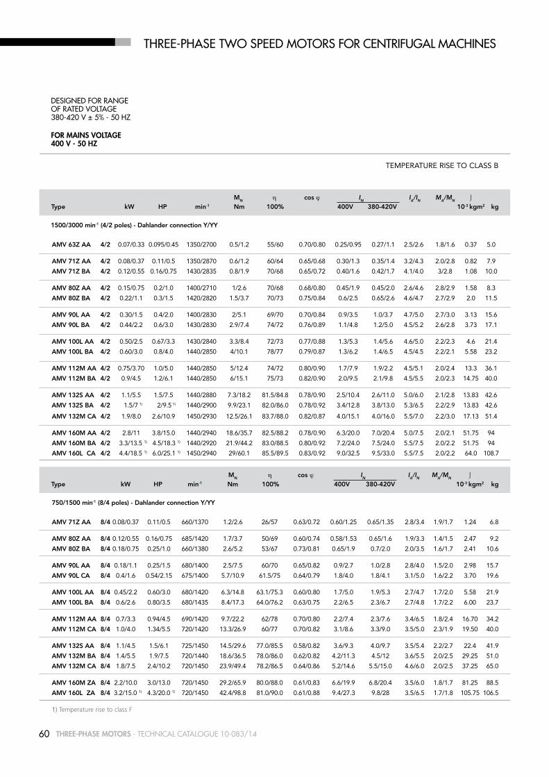
60 THREE-PHASE MOTORS - Technical caTalogue 10-083/14
THrEE-PHaSE TWO SPEED mOTOrS fOr CENTrifUGal maCHiNES
for mainS VoltaGe400 V - 50 HZ
DESiGNED fOr raNGE Of raTED VOlTaGE380-420 V ± 5% - 50 Hz
TEMPERATURE RISE TO CLASS B
MN η cos ϕ IN IA/IN MA/MN
Type kW HP min-1 Nm 100% 400V 380-420V 10-3 kgm2 kg
1500/3000 min-1 (4/2 poles) - Dahlander connection Y/YY
AMV 63z AA 4/2 0.07/0.33 0.095/0.45 1350/2700 0.5/1.2 55/60 0.70/0.80 0.25/0.95 0.27/1.1 2.5/2.6 1.8/1.6 0.37 5.0
AMV 71z AA 4/2 0.08/0.37 0.11/0.5 1350/2870 0.6/1.2 60/64 0.65/0.68 0.30/1.3 0.35/1.4 3.2/4.3 2.0/2.8 0.82 7.9
AMV 71z bA 4/2 0.12/0.55 0.16/0.75 1430/2835 0.8/1.9 70/68 0.65/0.72 0.40/1.6 0.42/1.7 4.1/4.0 3/2.8 1.08 10.0
AMV 80z AA 4/2 0.15/0.75 0.2/1.0 1400/2710 1/2.6 70/68 0.68/0.80 0.45/1.9 0.45/2.0 2.6/4.6 2.8/2.9 1.58 8.3
AMV 80z bA 4/2 0.22/1.1 0.3/1.5 1420/2820 1.5/3.7 70/73 0.75/0.84 0.6/2.5 0.65/2.6 4.6/4.7 2.7/2.9 2.0 11.5
AMV 90L AA 4/2 0.30/1.5 0.4/2.0 1400/2830 2/5.1 69/70 0.70/0.84 0.9/3.5 1.0/3.7 4.7/5.0 2.7/3.0 3.13 15.6
AMV 90L bA 4/2 0.44/2.2 0.6/3.0 1430/2830 2.9/7.4 74/72 0.76/0.89 1.1/4.8 1.2/5.0 4.5/5.2 2.6/2.8 3.73 17.1
AMV 100L AA 4/2 0.50/2.5 0.67/3.3 1430/2840 3.3/8.4 72/73 0.77/0.88 1.3/5.3 1.4/5.6 4.6/5.0 2.2/2.3 4.6 21.4
AMV 100L bA 4/2 0.60/3.0 0.8/4.0 1440/2850 4/10.1 78/77 0.79/0.87 1.3/6.2 1.4/6.5 4.5/4.5 2.2/2.1 5.58 23.2
AMV 112M AA 4/2 0.75/3.70 1.0/5.0 1440/2850 5/12.4 74/72 0.80/0.90 1.7/7.9 1.9/2.2 4.5/5.1 2.0/2.4 13.3 36.1
AMV 112M bA 4/2 0.9/4.5 1.2/6.1 1440/2850 6/15.1 75/73 0.82/0.90 2.0/9.5 2.1/9.8 4.5/5.5 2.0/2.3 14.75 40.0
AMV 132S AA 4/2 1.1/5.5 1.5/7.5 1440/2880 7.3/18.2 81.5/84.8 0.78/0.90 2.5/10.4 2.6/11.0 5.0/6.0 2.1/2.8 13.83 42.6
AMV 132S bA 4/2 1.5/7 1) 2/9.5 1) 1440/2900 9.9/23.1 82.0/86.0 0.78/0.92 3.4/12.8 3.8/13.0 5.3/6.5 2.2/2.9 13.83 42.6
AMV 132M CA 4/2 1.9/8.0 2.6/10.9 1450/2930 12.5/26.1 83.7/88.0 0.82/0.87 4.0/15.1 4.0/16.0 5.5/7.0 2.2/3.0 17.13 51.4
AMV 160M AA 4/2 2.8/11 3.8/15.0 1440/2940 18.6/35.7 82.5/88.2 0.78/0.90 6.3/20.0 7.0/20.4 5.0/7.5 2.0/2.1 51.75 94
AMV 160M bA 4/2 3.3/13.5 1) 4.5/18.3 1) 1440/2920 21.9/44.2 83.0/88.5 0.80/0.92 7.2/24.0 7.5/24.0 5.5/7.5 2.0/2.2 51.75 94
AMV 160L CA 4/2 4.4/18.5 1) 6.0/25.1 1) 1450/2940 29/60.1 85.5/89.5 0.83/0.92 9.0/32.5 9.5/33.0 5.5/7.5 2.0/2.2 64.0 108.7
MN η cos ϕ IN IA/IN MA/MN
Type kW HP min-1 Nm 100% 400V 380-420V 10-3 kgm2 kg
750/1500 min-1 (8/4 poles) - Dahlander connection Y/YY
AMV 71z AA 8/4 0.08/0.37 0.11/0.5 660/1370 1.2/2.6 26/57 0.63/0.72 0.60/1.25 0.65/1.35 2.8/3.4 1.9/1.7 1.24 6.8
AMV 80z AA 8/4 0.12/0.55 0.16/0.75 685/1420 1.7/3.7 50/69 0.60/0.74 0.58/1.53 0.65/1.6 1.9/3.3 1.4/1.5 2.47 9.2
AMV 80z bA 8/4 0.18/0.75 0.25/1.0 660/1380 2.6/5.2 53/67 0.73/0.81 0.65/1.9 0.7/2.0 2.0/3.5 1.6/1.7 2.41 10.6
AMV 90L AA 8/4 0.18/1.1 0.25/1.5 680/1400 2.5/7.5 60/70 0.65/0.82 0.9/2.7 1.0/2.8 2.8/4.0 1.5/2.0 2.98 15.7
AMV 90L CA 8/4 0.4/1.6 0.54/2.15 675/1400 5.7/10.9 61.5/75 0.64/0.79 1.8/4.0 1.8/4.1 3.1/5.0 1.6/2.2 3.70 19.6
AMV 100L AA 8/4 0.45/2.2 0.60/3.0 680/1420 6.3/14.8 63.1/75.3 0.60/0.80 1.7/5.0 1.9/5.3 2.7/4.7 1.7/2.0 5.58 21.9
AMV 100L bA 8/4 0.6/2.6 0.80/3.5 680/1435 8.4/17.3 64.0/76.2 0.63/0.75 2.2/6.5 2.3/6.7 2.7/4.8 1.7/2.2 6.00 23.7
AMV 112M AA 8/4 0.7/3.3 0.94/4.5 690/1420 9.7/22.2 62/78 0.70/0.80 2.2/7.4 2.3/7.6 3.4/6.5 1.8/2.4 16.70 34.2
AMV 112M CA 8/4 1.0/4.0 1.34/5.5 720/1420 13.3/26.9 60/77 0.70/0.82 3.1/8.6 3.3/9.0 3.5/5.0 2.3/1.9 19.50 40.0
AMV 132S AA 8/4 1.1/4.5 1.5/6.1 725/1450 14.5/29.6 77.0/85.5 0.58/0.82 3.6/9.3 4.0/9.7 3.5/5.4 2.2/2.7 22.4 41.9
AMV 132M bA 8/4 1.4/5.5 1.9/7.5 720/1440 18.6/36.5 78.0/86.0 0.62/0.82 4.2/11.3 4.5/12 3.6/5.5 2.0/2.5 29.25 51.0
AMV 132M CA 8/4 1.8/7.5 2.4/10.2 720/1450 23.9/49.4 78.2/86.5 0.64/0.86 5.2/14.6 5.5/15.0 4.6/6.0 2.0/2.5 37.25 65.0
AMV 160M zA 8/4 2.2/10.0 3.0/13.0 720/1450 29.2/65.9 80.0/88.0 0.61/0.83 6.6/19.9 6.8/20.4 3.5/6.0 1.8/1.7 81.25 88.5
AMV 160L zA 8/4 3.2/15.0 1) 4.3/20.0 1) 720/1450 42.4/98.8 81.0/90.0 0.61/0.88 9.4/27.3 9.8/28 3.5/6.5 1.7/1.8 105.75 106.5
1) Temperature rise to class F

61THREE-PHASE MOTORS - Technical caTalogue 10-083/14
THrEE-PHaSE TWO SPEED mOTOrS fOr CENTrifUGal maCHiNES
for mainS VoltaGe400 V - 50 HZ
DESiGNED fOr raNGE Of raTED VOlTaGE380-420 V ± 5% - 50 Hz
TEMPERATURE RISE TO CLASS B
MN η cos ϕ IN IA/IN MA/MN
Type kW HP min-1 Nm 100% 400V 380-420V 10-3 kgm2 kg
1500/1000 min-1 (4/6 poles) - separate windings
AMV 71z AA 4/6 0.25/0.08 0.33/0.11 1370/900 1.7/0.4 60/40 0.80/0.70 0.75/0.4 0.8/0.45 3.0/2.5 1.6/1.6 1.15 6.7
AMV 71z bA 4/6 0.37/0.13 0.50/0.18 1360/880 2.6/1.4 62/44 0.80/0.70 1.0/0.6 1.1/0.7 3.2/2.6 1.6/1.6 1.24 7.2
AMV 80z AA 4/6 0.55/0.18 0.75/0.25 1380/920 3.8/1.9 60/42 0.83/0.82 1.60/0.75 1.7/0.8 3.5/2.4 1.6/1.0 1.97 8.3
AMV 80z bA 4/6 0.75/0.25 1.0/0.33 1400/940 5.1/2.5 70/60 0.82/0.72 1.8/0.8 1.9/0.9 4.2/2.6 1.6/1.3 4.05 14
AMV 90S AA 4/6 0.75/0.24 1.0/0.32 1400/950 5.1/2.4 70/60 0.82/0.72 1.9/0.8 2.0/0.9 4.2/2.6 1.6/1.3 4.05 14
AMV 90L bA 4/6 1.1/0.37 1.5/0.50 1400/930 7.5/3.8 70/60 0.81/0.74 2.8/1.2 3.0/1.3 4.3/2.7 1.6/1.2 4.78 16.4
AMV 90L CA 4/6 1.5/0.5 2.0/0.67 1420/950 10.1/5 73/64 0.80/0.70 3.52/1.52 3.7/1.6 4.8/2.6 1.5/1.3 5.98 20.5
AMV 100L AA 4/6 1.85/0.60 2.5/0.75 1400/920 12.6/6.2 74/64 0.80/0.73 4.6/1.9 4.8/2.1 4.8/3.1 1.8/1.5 6.73 23.4
AMV 100L bA 4/6 2.2/0.75 3.0/1.0 1420/950 14.8/7.5 76/66 0.79/0.75 5.1/2.1 5.3/2.2 5.0/3.5 1.7/1.3 9.25 22.6
AMV 112M AA 4/6 3/1.0 4.0/1.34 1440/970 19.9/9.8 80/73 0.81/0.65 6.6/3.0 6.8/3.2 5.8/4.6 2.5/2.1 13.3 30.4
AMV 132S AA 4/6 3.8/1.3 5.2/1.8 1460/970 24.9/12.8 85.0/75.0 0.8/0.72 8.1/3.5 8.5/4 6.5/4.0 2.2/1.7 22.4 41.9
AMV 132M bA 4/6 4.4/1.5 6.0/2.0 1460/970 28.8/14.8 86.0/78.2 0.85/0.73 8.7/3.8 9.2/4.3 6.5/4.4 2.2/1.7 29.25 51.0
AMV 132M CA 4/6 5.5/1.8 7.5/2.4 1460/970 36/17.7 86.8/80.0 0.84/0.74 10.9/4.4 12.0/4. 7.0/4.7 2.6/1.8 37.25 65.0
AMV 132M DA 4/6 6.3/2.2 1) 8.6/3.0 1) 1460/970 41.2/21.7 86.8/81.0 0.84/0.73 12.5/5.4 13.5/5. 7.2/4.8 2.6/1.9 37.25 66.0
AMV 160M AA 4/6 7.5/2.5 10.0/3.4 1470/975 48.7/24.5 87.5/83.0 0.83/0.75 14.9/5.8 15.6/6.0 8.3/4.5 2.5/1.9 81.25 88.5
AMV 160L bA 4/6 11.0/3.7 15.0/5.0 1470/970 71.5/36.4 88.0/84.2 0.81/0.73 22.5/8.7 23.4/9.0 8.0/4.8 2.4/1.8 105.75 106.5
AMV 160L CA 4/6 13.0/4.0 1) 17.7/5.4 1) 1460/970 85/39.4 88.0/84.5 0.81/0.72 26.3/9.5 27.5/10 8.0/4.8 2.4/1.9 105.75 106.5
MN η cos ϕ IN IA/IN MA/MN
Type kW HP min-1 Nm 100% 400V 380-420V 10-3 kgm2 kg
1000/750 min-1 (6/8 poles) - separate windings
AMV 80z AA 6/8 0.25/0.11 0.33/0.15 930/720 2.6/1.5 53/49 0.79/0.62 0.9/0.55 1.0/0.7 2.9/3.0 1.6/1.8 1.97 7.9
AMV 80z bA 6/8 0.37/0.15 0.50/0.25 920/715 3.8/2 52/47 0.81/0.63 1.3/0.8 1.4/0.9 2.8/2.8 1.4/1.9 2.47 9.5
AMV 90L AA 6/8 0.55/0.22 0.75/0.30 960/740 5.5/2.8 65/47 0.62/0.51 2.0/1.4 2.1/1.5 3.9/2.9 2.5/2.1 4.78 16.2
AMV 90L bA 6/8 0.75/0.30 1.0/0.40 940/720 7.6/4 64/45.5 0.67/0.52 2.5/1.85 2.7/1.9 3.4/2.6 2.2/1.9 4.78 16.2
AMV 100L AA 6/8 1.1/0.45 1.5/0.60 950/710 11.1/6.1 70.6/58 0.71/0.67 3.1/1.7 3.3/1.8 4.3/2.8 2.0/1.3 9.43 22.0
AMV 112M AA 6/8 1.5/0.6 2.0/0.80 970/720 14.8/8 75.8/65 0.65/0.60 4.4/2.3 3.7/2.5 5.5/3.4 2.8/2.1 18.70 39.0
AMV 132S zA 6/8 2.2/0.9 3.0/1.2 970/715 21.7/12 78.0/69.0 0.67/0.55 6.1/3.5 6.7/4.0 4.8/4.0 1.6/1.6 29.5 42.5
AMV 132M YA 6/8 3/1.2 4.0/1.6 960/715 29.8/16 80/72 0.7/0.55 7.8/4.4 8.2/4.8 4.8/4.1 1.6/1.6 37.75 55.5
AMV 132M zA 6/8 4/1.6 5.5/2.2 960/715 39.8/21.4 81.0/74.0 0.78/0.6 9.2/5.2 9.8/5.6 5.3/4.4 1.7/1.7 44.5 64.1
AMV 160M YA 6/8 5.5/2.2 7.5/3.0 970/730 54.1/28.8 83/76 0.77/0.6 12.5/7 13.5/7.5 5.7/5.6 1.6/1.9 112.7 88.0
AMV 160M zA 6/8 7/3 9.5/4.1 970/730 68.9/39.2 84/77 0.80/0.65 15/8.7 16/9.3 6.0/5.8 1.7/2.2 150.25 97.5
1) Temperature rise to class F

62 THREE-PHASE MOTORS - Technical caTalogue 10-083/14
IEC Poles kW H A b C K 1) Ab bb CA AD 2) HD 2) AC HC 80 2 - 4 all 80 125 100 50 10 153 125 89 129 209 160 162
90S 2 - 4 - 6 all 90 140 100 56 10 170 150 116 138 228 180 181
90L 2 2.2 90 140 125 56 10 170 150 91 138 228 180 181
2 3 90 140 125 56 10 170 150 114 138 228 180 181
4 - 6 all 90 140 125 56 10 170 150 91 138 228 180 181 100L 2 all 100 160 140 63 11 192 166 110 145 245 196 198
4 2.2 100 160 140 63 11 192 166 110 145 245 196 198
4 3 100 160 140 63 11 192 166 125 145 245 194 198
6 1.1 100 160 140 63 11 192 166 110 145 245 196 198
6 1.5 100 160 140 63 11 192 166 125 145 245 194 198 112M 2 4 - 5.5 112 190 140 70 12.5 220 176 126 160 272 225 225
2 7.5 112 190 140 70 12.5 220 176 148 160 272 222 225
4-6 all 112 190 140 70 12.5 220 176 126 160 272 225 225 132S 2 5.5 132 216 140 89 12 256 180 134 194 326 248 261
2 7.5 132 216 140 89 12 256 180 154 194 326 248 261
4 - 6 all 132 216 140 89 12 256 180 134 194 326 248 261
132M 2 9.2 - 11 132 216 178 89 12 256 218 156 194 326 248 261
2 15 132 216 178 89 12 256 218 207 194 326 248 261
4 7.5 132 216 178 89 12 256 218 156 194 326 248 261
4 9.2 132 216 178 89 12 256 218 207 194 326 248 261
6 4 132 216 178 89 12 256 218 136 194 326 248 261
6 5.5 132 216 178 89 12 256 218 156 194 326 248 261 160M 2 - 4 - 6 all 160 254 210 108 14 320 270 180 238 398 317 316
160L 2 - 4 - 6 all 160 254 254 108 14 320 310 180 238 398 317 316
THrEE-PHaSE framE SizE 80 - 160 im B3amPE SEriES - alUmiNiUm allOY framE
HC
AD
ABA
K1
HD
AD
HAH
DAEA
AC
CA
AA
LLC
AFAL
E
DBA
BBB
LB
K
C
F
DBGA
GD

63THREE-PHASE MOTORS - Technical caTalogue 10-083/14
THrEE-PHaSE framE SizE 80 - 160 im B3amPE SEriES - alUmiNiUm allOY framE
HC
AD
ABA
K1
HD
AD
HAH
DAEA
AC
CA
AA
LLC
AFAL
E
DBA
BBB
LB
K
C
F
DBGA
GD
IEC Poles kW HA K1 L Lb LC AL AF bA AA D/DA E/EA F GD GA Db3)
80 2 - 4 all 9.5 14 272 232 319 79 116 28.5 34.5 19 40 6 6 21.5 M6
90S 2 - 4 - 6 all 11 15 317 267 372 85 116 28/53 37 24 50 8 7 27 M8
90L 2 2.2 11 15 317 267 372 85 116 28/53 37 24 50 8 7 27 M8
2 3 11 15 340 290 395 85 116 28/53 37 24 50 8 7 27 M8
4 - 6 all 11 15 317 267 372 85 116 28/53 37 24 50 8 7 27 M8 100L 2 all 12 17 366 306 433 91 116 38 44 28 60 8 7 31 M10
4 2.2 12 17 366 306 433 91 116 38 44 28 60 8 7 31 M10
4 3 12 17 381 321 448 91 116 38 44 28 60 8 7 31 M10
6 1.1 12 17 366 306 433 91 116 38 44 28 60 8 7 31 M10
6 1.5 12 17 381 321 448 91 116 38 44 28 60 8 7 31 M10 112M 2 4 - 5.5 15 19 388 328 456 92 116 46 48 28 60 8 7 31 M10
2 7.5 15 19 410 350 478 92 116 46 48 28 60 8 7 31 M10
4 all 15 19 388 328 456 92 116 46 48 28 60 8 7 31 M10 132S 2 5.5 17 20 445 365 523 100 133 45 59 38 80 10 8 41 M12
2 7.5 17 20 465 385 543 100 133 45 59 38 80 10 8 41 M12
4 - 6 all 17 20 445 365 523 100 133 45 59 38 80 10 8 41 M12
132M 2 9.2 - 11 17 20 505 425 583 120 133 45 59 38 80 10 8 41 M12
2 15 17 20 556 476 634 120 133 45 59 38 80 10 8 41 M12
4 7.5 17 20 505 425 583 120 133 45 59 38 80 10 8 41 M12
4 9.2 17 20 556 476 634 120 133 45 59 38 80 10 8 41 M12
6 4 17 20 485 405 563 120 133 45 59 38 80 10 8 41 M12
6 5.5 17 20 505 425 583 120 133 45 59 38 80 10 8 41 M12 160M 2 - 4 - 6 all 23 18 608 498 668 146 150 65 76 42/28 110/60 12/8 8/7 45/31 M16/M10
160L 2 - 4 -6 all 23 18 652 542 712 168 150 65 76 42/28 110/60 12/8 8/7 45/31 M16/M10
1) Clearance hole for screw 2) Maximun distance 3) Centering holes in shaft extensions to DIN 332 part 2

64 THREE-PHASE MOTORS - Technical caTalogue 10-083/14
THrEE-PHaSE framE SizE 90 - 160 im B3 amPH SEriES - alUmiNiUm allOY framE
HC
AD
ABA
K1
HD
AD
HAH
DAEA
AC
CA
AA
LLC
AFAL
E
DBA
BBB
LB
K
C
F
DBGA
GD
IEC Poles kW HA K1 L Lb LC AL AF bA AA D/DA E/EA F GD GA Db 3)
90S 2 - 4 all 11 15 317 267 372 85 116 28/53 37 24 50 8 7 27 M8
90L 2 - 4 all 11 15 317 267 372 85 116 28/53 37 24 50 8 7 27 M8 100L 2 all 12 17 366 306 433 91 116 38 44 28 60 8 7 31 M10 112M 2 - 4 all 15 19 388 328 456 92 116 46 48 28 60 8 7 31 M10 132S 2 5.5 17 20 445 365 523 100 133 45 59 38 80 10 8 41 M12
2 7.5 17 20 465 385 543 100 133 45 59 38 80 10 8 41 M12
4 5.5 17 20 445 365 523 100 133 45 59 38 80 10 8 41 M12
132M 2 all 17 20 505 425 583 120 133 45 59 38 80 10 8 41 M12
4 all 17 20 485 405 563 120 133 45 59 38 80 10 8 41 M12 160M 2-4 all 23 18 608 498 668 146 150 65 76 42/28 110/60 12/8 8/7 45/31 M16/M10
160L 2-4 all 23 18 652 542 712 168 150 65 76 42/28 110/60 12/8 8/7 45/31 M16/M10
1) Clearance hole for screw 2) Maximun distance 3) Centering holes in shaft extensions to DIN 332 part 2
IEC Poles kW H A b C K 1) Ab bb CA AD 2) HD 2) AC HC
90S 2 - 4 all 90 140 100 56 10 170 150 116 138 228 180 181
90L 2 - 4 all 90 140 125 56 10 170 150 91 138 228 180 181 100L 2 all 100 160 140 63 11 192 166 110 145 245 196 198 112M 2 - 4 all 112 190 140 70 12,5 220 176 126 160 272 225 225 132S 2 5.5 132 216 140 89 12 256 180 134 194 326 248 261
2 7.5 132 216 140 89 12 256 180 154 194 326 248 261
4 5.5 132 216 140 89 12 256 180 134 194 326 248 261
132M 2 all 132 216 178 89 12 256 218 156 194 326 248 261
4 all 132 216 178 89 12 256 218 136 194 326 248 261 160M 2-4 all 160 254 210 108 14 320 270 180 238 398 317 31
160L 2-4 all 160 254 254 108 14 320 310 180 238 398 317 316

65THREE-PHASE MOTORS - Technical caTalogue 10-083/14
HC
AD
ABA
K1
HD
AD
HAH
DAEA
AC
CA
AA
LLC
AFAL
E
D
BA
BBB
LB
K
C
F
DBGA
GD
THrEE-PHaSE framE SizE 71-160 imB3amHE SEriES - allUmiNiUm allOY framE
IEC Poles kW H A b C K 1) Ab bb CA AD 2) HD 2) AC HC 71 2 0.75 71 112 90 45 8 135 108 83 110 181 139 142 80 2 - 4 all 80 125 100 50 10 153 125 89 129 209 160 162
90S 2 - 4 all 90 140 100 56 10 170 150 116 138 228 180 18190L 2 2.2 90 140 125 56 10 170 150 91 138 228 180 181 2 3 90 140 125 56 10 170 150 114 138 228 180 181 4 all 90 140 125 56 10 170 150 91 138 228 180 181 100 2 all 100 160 140 63 11 192 166 110 145 245 196 198 4 2.2 100 160 140 63 11 192 166 110 145 245 196 198 4 3 100 160 140 63 11 192 166 125 145 245 194 198 112 2 4 - 5.5 112 190 140 70 12.5 220 176 126 160 272 225 225 2 7.5 112 190 140 70 12.5 220 176 148 160 272 222 225 4 all 112 190 140 70 12.5 220 176 126 160 272 225 225 132S 2 5.5 132 216 140 89 12 256 180 134 194 326 248 261 2 7.5 132 216 140 89 12 256 180 154 194 326 248 261 4 5.5 132 216 140 89 12 256 180 134 194 326 248 261132M 2 9.2 - 11 132 216 178 89 12 256 218 156 194 326 248 261 2 15 132 216 178 89 12 256 218 207 194 326 248 261 4 all 132 216 178 89 12 256 218 136 194 326 248 261 160M 2 - 4 all 160 254 210 108 14 320 270 180 238 398 317 316160L 2 - 4 all 160 254 254 108 14 320 310 180 238 398 317 316
IEC Poles kW HA K1 L Lb LC AL AF bA AA D/DA E/EA F GD GA Db3)
71 2 0.75 9 11 246 216 278 69 92 28 31 14 30 5 5 16 M5 80 2 - 4 all 9.5 14 272 232 319 79 116 28.5 34.5 19 40 6 6 21.5 M6 90S 2 - 4 all 11 15 317 267 372 85 116 28/53 37 24 50 8 7 27 M890L 2 2.2 11 15 317 267 372 85 116 28/53 37 24 50 8 7 27 M8 2 3 11 15 340 290 395 85 116 28/53 37 24 50 8 7 27 M8 4 all 11 15 317 267 372 85 116 28/53 37 24 50 8 7 27 M8 100L 2 all 12 17 366 306 433 91 116 38 44 28 60 8 7 31 M10 4 2.2 12 17 366 306 433 91 116 38 44 28 60 8 7 31 M10 4 3 12 17 381 321 448 91 116 38 44 28 60 8 7 31 M10 112M 2 4 - 5.5 15 19 388 328 456 92 116 46 48 28 60 8 7 31 M10 2 7.5 15 19 410 350 478 92 116 46 48 28 60 8 7 31 M10 4 all 15 19 388 328 456 92 116 46 48 28 60 8 7 31 M10 132S 2 5.5 17 20 445 365 523 100 133 45 59 38 80 10 8 41 M12 2 7.5 17 20 465 385 543 100 133 45 59 38 80 10 8 41 M12 4 5.5 17 20 445 365 523 100 133 45 59 38 80 10 8 41 M12132M 2 9.2 - 11 17 20 505 425 583 120 133 45 59 38 80 10 8 41 M12 2 15 17 20 556 476 634 120 133 45 59 38 80 10 8 41 M12 4 all 17 20 485 405 563 120 133 45 59 38 80 10 8 41 M12 160M 2 - 4 all 23 18 608 498 668 146 150 65 76 42/28 110/60 12/8 8/7 45/31 M16/M10160L 2 - 4 all 23 18 652 542 712 168 150 65 76 42/28 110/60 12/8 8/7 45/31 M16/M10
1) Clearance hole for screw 2) Maximun distance 3) Centering holes in shaft extensions to DIN 332 part 2

66 THREE-PHASE MOTORS - Technical caTalogue 10-083/14
THrEE-PHaSE framE SizE 80 - 160 im B3 amH SEriES - alUmiNiUm allOY framE
HC
AD
ABA
K1
HD
AD
HAH
DAEA
AC
CA
AA
LLC
AFAL
E
DBA
BBB
LB
K
C
F
DBGA
GD
IEC Poles kW HA K1 L Lb LC AL AF bA AA D/DA E/EA F GD GA Db 3)
80 2 - 4 all 9.5 14 272 232 319 79 116 28.5 34.5 19 40 6 6 21.5 M6 90S 2 - 4 all 11 15 317 267 372 85 116 28/53 37 24 50 8 7 27 M890L 2-4-6 all 11 15 317 267 372 85 116 28/53 37 24 50 8 7 27 M8 100L 2 all 12 17 366 306 433 91 116 38 44 28 60 8 7 31 M10 4 2.2 12 17 366 306 433 91 116 38 44 28 60 8 7 31 M10 4 3 12 17 381 321 448 91 116 38 44 28 60 8 7 31 M10 6 1.1 12 17 381 321 448 91 116 38 44 28 60 8 7 31 M10 112M 2-4-6 all 15 19 388 328 456 92 116 46 48 28 60 8 7 31 M10 132S 2 5.5 17 20 445 365 523 100 133 45 59 38 80 10 8 41 M12 2 7.5 17 20 465 385 543 100 133 45 59 38 80 10 8 41 M12 4 5.5 17 20 445 365 523 100 133 45 59 38 80 10 8 41 M12 6 3 17 20 445 365 523 100 133 45 59 38 80 10 8 41 M12132M 2 all 17 20 505 425 583 120 133 45 59 38 80 10 8 41 M12 4 all 17 20 485 405 563 120 133 45 59 38 80 10 8 41 M12 6 4 17 20 485 405 563 120 133 45 59 38 80 10 8 41 M12 6 5.5 17 20 505 425 583 120 133 45 59 38 80 10 8 41 M12 160M 2-4-6 all 23 18 608 498 668 146 150 65 76 42/28 110/60 12/8 8/7 45/31 M16/M10160L 2-4-6 all 23 18 652 542 712 168 150 65 76 42/28 110/60 12/8 8/7 45/31 M16/M10
1) Clearance hole for screw 2) Maximun distance 3) Centering holes in shaft extensions to DIN 332 part 2
IEC Poles kW H A b C K 1) Ab bb CA AD 2) HD 2) AC HC 80 2 - 4 all 80 125 100 50 10 153 125 89 129 209 160 162 90S 2 - 4 all 90 140 100 56 10 170 150 116 138 228 180 18190L 2-4-6 all 90 140 125 56 10 170 150 91 138 228 180 181 100L 2 all 100 160 140 63 11 192 166 110 145 245 196 198 4 2.2 100 160 140 63 11 192 166 110 145 245 196 198 4 3 100 160 140 63 11 192 166 125 145 245 194 198 6 1.1 100 160 140 63 11 192 166 125 145 245 194 198 112M 2-4-6 all 112 190 140 70 12.5 220 176 126 160 272 225 225 132S 2 5.5 132 216 140 89 12 256 180 134 194 326 248 261 2 7.5 132 216 140 89 12 256 180 154 194 326 248 261 4 5.5 132 216 140 89 12 256 180 134 194 326 248 261 6 3 132 216 140 89 12 256 180 134 194 326 248 261132M 2 all 132 216 178 89 12 256 218 156 194 326 248 261 4 all 132 216 178 89 12 256 218 136 194 326 248 261 6 4 132 216 178 89 12 256 218 136 194 326 248 261 6 5.5 132 216 178 89 12 256 218 156 194 326 248 261 160M 2-4-6 all 160 254 210 108 14 320 270 180 238 398 317 316160L 2-4-6 all 160 254 254 108 14 320 310 180 238 398 317 316

67THREE-PHASE MOTORS - Technical caTalogue 10-083/14
HC
AD
ABA
K1
HD
AD
HAH
DAEA
AC
CA
AA
LLC
AFAL
E
D
BA
BBB
LB
K
C
F
DBGA
GD
THrEE-PHaSE framE SizE 71-160 imB3amEE SEriES - allUmiNiUm allOY framE
IEC Poles kW H A b C K1) Ab bb CA AD2) HD2) AC HC
71 2 0.75 71 112 90 45 8 135 107 81 110 181 139 142
80 2-4 all 80 125 100 50 10 153 125 89 129 209 160 162
90S 2-4-6 all 90 140 100 56 10 170 150 116 138 228 180 18190L 2-4-6 all 90 140 125 56 10 170 150 91 138 228 180 181
100 2-4-6 all 100 160 140 63 11 192 166 110 145 245 196 198
112 2 4-5.5 112 190 140 70 12.5 220 176 126 160 272 225 225 2 7.5 112 190 140 70 12.5 220 176 148 160 272 222 225 4 4 112 190 140 70 12.5 220 176 126 160 272 225 225 4 5.5 112 190 140 70 12.5 220 176 148 160 272 222 225 6 all 112 190 140 70 12.5 220 176 126 160 272 225 225
132S 2-4-6 all 132 216 140 89 12 256 180 134 194 326 248 261132M 2 9.2 132 216 178 89 12 256 218 136 194 326 248 261 2 11 132 216 178 89 12 256 218 156 194 326 248 261 2 15 132 216 178 89 12 256 218 207 194 326 248 261 4 7.5 132 216 178 89 12 256 218 136 194 326 248 261 4 9.2 132 216 178 89 12 256 218 136 194 326 248 261 6 4 132 216 178 89 12 256 218 136 194 326 248 261 6 5.5 132 216 178 89 12 256 218 136 194 326 248 261
160M 2-4-6 all 160 254 210 108 14 320 270 180 238 398 317 316160L 2-4-6 all 160 254 254 108 14 320 310 180 238 398 317 316
IEC Poles kW HA K1 L Lb LC AL AF bA AA D/DA E/EA F GD GA Db3)
71 2 0.75 9 11 246 216 278 69 92 28 31 14 30 5 5 16 M5
80 2-4 all 9.5 14 272 232 319 79 116 29 35 19 40 6 6 21.5 M6
90S 2-4-6 all 11 15 317 267 372 85 116 28/53 37 24 50 8 7 27 M890L 2-4-6 all 11 15 317 267 372 85 116 28/53 37 24 50 8 7 27 M8
100 2-4-6 all 12 17 366 306 433 91 116 38 44 28 60 8 7 31 M10
112 2 4-5.5 15 19 388 328 456 92 116 46 48 28 60 8 7 31 M10 2 7.5 15 19 410 350 478 92 116 46 48 28 60 8 7 31 M10 4 4 15 19 388 328 456 92 116 46 48 28 60 8 7 31 M10 4 5.5 15 19 410 350 478 92 116 46 48 28 60 8 7 31 M10 6 all 15 19 388 328 456 92 116 46 48 28 60 8 7 31 M10
132S 2-4-6 all 17 20 445 365 523 102 133 45 59 38 80 10 8 41 M12132M 2 9.2 17 20 485 405 563 122 133 45 59 38 80 10 8 41 M12 2 11 17 20 505 425 583 122 133 45 59 38 80 10 8 41 M12 2 15 17 20 556 476 634 122 133 45 59 38 80 10 8 41 M12 4 7.5 17 20 485 405 563 122 133 45 59 38 80 10 8 41 M12 4 9.2 17 20 505 425 583 122 133 45 59 38 80 10 8 41 M12 6 4 17 20 485 405 563 122 133 45 59 38 80 10 8 41 M12 6 5.5 17 20 505 425 583 122 133 45 59 38 80 10 8 41 M12
160M 2-4-6 all 23 18 608 498 668 146 150 65 76 42/28 110/60 12/8 8/7 45/31 M16/M10160L 2-4-6 all 23 18 652 542 712 168 150 65 76 42/28 110/60 12/8 8/7 45/31 M16/M10
1) Clearance hole for screw 2) Maximun distance 3) Centering holes in shaft extensions to DIN 332 part 2

68 THREE-PHASE MOTORS - Technical caTalogue 10-083/14
THrEE-PHaSE framE SizE 56 - 160 im B3am SEriES - alUmiNiUm allOY framE
HC
AD
ABA
K1
HD
AD
HAH
DAEA
AC
CA
AA
LLC
AFAL
E
DBA
BBB
LB
K
C
F
DBGA
GD
1) Clearance hole for screw 2) Maximum dimension 3) Centering holes in shaft extensions to DIN 332 part 2
4) Only for MT A2 5) Only for LR A4
IEC H A b C K 1) Ab bb CA AD 2) HD 2) AC HC HA 56 56 90 71 36 6 107 86 64 92 148 110 109 8
63 63 100 80 40 7 120 100 72 96 159 124 120 8
71 71 112 90 45 8 135 108 83 110 181 139 142 9
80 80 125 100 50 10 153 125 89 129 209 160 162 9.5
90S 90 140 100 56 10 170 150 116 138 228 180 181 1190L 90 140 125 56 10 170 150 91 138 228 180 181 11
100 100 160 140 63 11 192 166 110 145 245 196 198 12
112 112 190 140 70 12.5 220 175 126 161 273 225 226 15
132S 132 216 140 89 12 256 180 134 195 327 248 261 17132M 132 216 178 89 12 256 218 136 195 327 248 261 17132M 4) 132 216 178 89 12 256 218 166 195 327 248 261 17
160M 160 254 210 108 14 320 270 180 238 398 317 316 23160L 160 254 254 108 14 320 310 180 238 398 317 316 23160L 5) 160 254 254 108 14 320 310 210 238 398 317 316 23
IEC K1 L Lb LC AL AF bA AA D/DA E/EA F GD GA Db3)
56 9 188 168 211 61 92 27 27 9 20 3 3 10.2 M3
63 11 211 188 238 63 92 29 30 11 23 4 4 12.5 M4
71 11 246 216 278 69 92 28 31 14 30 5 5 16 M5
80 14 272 232 319 79 116 28.5 34.5 19 40 6 6 21.5 M6
90S 15 317 267 372 85 116 28/53 37 24 50 8 7 27 M890L 15 317 267 372 85 116 28/53 37 24 50 8 7 27 M8
100L 17 366 306 433 91 116 38 44 28 60 8 7 31 M10
112M 19 388 328 456 91.5 116 46 48 28 60 8 7 31 M10
132S 20 442 362 523 100 133 45 59 38 80 10 8 41 M12132M 20 482 402 563 120 133 45 59 38 80 10 8 41 M12132M 4) 20 500 420 593 120 133 45 59 38 80 10 8 41 M12
160M 18 608 498 718 146 150 65 76 42 110 12 8 45 M16160L 18 652 542 762 168 150 65 76 42 110 12 8 45 M16160L 5) 18 678 568 678 168 150 65 76 42 110 12 8 45 M16

69THREE-PHASE MOTORS - Technical caTalogue 10-083/14
THrEE-PHaSE framE SizE 56 - 160 im B14, im B5amPE-amPH-amHE-amH-amEE-am SEriES - alUmiNiUm allOY framE
T
LA
E
P
D
N
E S
M
GD
GA
F
DB
MS
T
P
E
LA
D
NE
im B5im B14
IEC P N LA M T S P N LA M T S M N P T LA S1)
56 80 50 8 65 2.5 M5 105 70 8 85 2.5 M6 100 80 120 2.5 7 M6
63 90 60 8 75 2.5 M5 120 80 8 100 2.5 M6 115 95 140 3 8 M8
71 105 70 8 85 2.5 M6 140 95 8 115 3 M8 130 110 160 3.5 10 M8
80 120 80 9 100 3 M6 160 110 8.5 130 3.5 M8 165 130 200 3.5 10 M10
90 140 95 9 115 3 M8 160 110 9 130 3.5 M8 165 130 200 3.5 12 M10
100 160 110 10 130 3.5 M8 200 130 12 165 3.5 M10 215 180 250 4 14 M12
112 160 110 10 130 3.5 M8 200 130 12 165 3.5 M10 215 180 250 4 14 M12
132 200 130 30 165 3.5 M10 250 180 12 215 4 M12 265 230 300 4 14 M12
160 250 180 12 215 4 M12 300 230 12 265 5 M16 300 250 350 5 15 M16
1) Clearence hole for screw. Hole as standard for 132 to 160 frame size
SMALL FLANGE b14 LARGE FLANGE b14 FLANGE b5
GD
F
GA
D
E
EB ED
DB
EG
IEC D E F h9 GD GA Db1) EG Eb ED
56 9 j6 20 3 3 10.2 M3 10 15 2.5
63 11 j6 23 4 4 12.5 M4 10 15 4
71 14 j6 30 5 5 16 M5 12.5 20 4 80 19 j6 40 6 6 21.5 M6 16 30 4
90 24 j6 50 8 7 27 M8 19 40 4
100 28 j6 60 8 7 31 M10 22 50 4
112 28 j6 60 8 7 31 M10 22 50 4
132 38 k6 80 10 8 41 M12 28 70 4
160 42 k6 110 12 8 45 M16 36 100 4
1) Centering holes in shaft extension to DIN 332 part 2

70 THREE-PHASE MOTORS - Technical caTalogue 10-083/14
THrEE-PHaSE framE SizE 180 - 315 im B3amHE SEriES - CaST irON framE
IEC Poles HA L Lb AL AA D E F GD GA Db 2
180M ≥ 2 27 687 577 241 75 48 110 14 9 51.5 M16 180L ≥ 2 27 725 615 241 75 48 110 14 9 51.5 M16 200 ≥ 2 25 768 658 285 80 55 110 16 10 59 M20 225S ≥ 4 28 814 674 295 85 60 140 18 11 64 M20 225M 2 28 809 699 295 85 55 110 16 10 59 M20 ≥ 4 28 839 699 295 85 60 140 18 11 64 M20 250 2 30 918 778 342 80 60 140 18 11 64 M20 ≥ 4 30 918 778 342 80 65 140 18 11 69 M20 280S 2 34 984 844 400 100 65 140 18 11 69 M20 ≥ 4 34 984 844 400 100 75 140 20 12 79.5 M20 280M 2 34 1035 895 400 100 65 140 18 11 69 M20 ≥ 4 34 1035 895 400 100 75 140 20 12 79.5 M20 315S 2 45 1160 1205 292 120 65 140 18 11 69 M20 ≥ 4 45 1190 1235 292 120 80 170 22 14 85 M20 315M 2 45 1310 1355 292 120 65 140 18 11 69 M20 ≥ 4 45 1340 1385 292 120 80 170 22 14 85 M20 315L 2 45 1310 1355 292 120 65 140 18 11 69 M20 ≥ 4 45 1340 1385 292 120 80 170 22 14 85 M20
IEC Poles H A b C K 1) Ab bb AD HD AC 180M ≥ 2 180 279 241 121 15 354 311 268 439 360 180L ≥ 2 180 279 279 121 15 354 348 268 439 360 200 ≥ 2 200 318 305 133 19 393 370 297 497 399 225S ≥ 4 225 356 286 149 19 440 361 333 553 465 225M 2 225 356 311 149 19 440 386 333 553 465 ≥ 4 225 356 311 149 19 440 386 333 553 465 250 2 250 406 349 168 24 484 443 366 616 506 ≥ 4 250 406 349 168 24 484 443 366 616 506 280S 2 280 457 368 190 24 560 459 395 668 559 ≥ 4 280 457 368 190 24 560 459 395 668 559 280M 2 280 457 419 190 24 560 510 395 668 559 ≥ 4 280 457 419 190 24 560 510 395 668 559 315S 2 315 508 406 216 28 628 590 530 840 680 ≥ 4 315 508 406 216 28 628 590 530 840 680 315M 2 315 508 457 216 28 628 672 530 840 680 ≥ 4 315 508 457 216 28 628 672 530 840 680 315L 2 315 508 508 216 28 628 672 530 840 680 ≥ 4 315 508 508 216 28 628 672 530 840 680
HC
AD
ABA
K1
HD
AD
HAH
DAEA
AC
CA
AA
LLC
AFAL
E
D
BA
BBB
LB
K
C
F
DBGA
GD

71THREE-PHASE MOTORS - Technical caTalogue 10-083/14
THrEE-PHaSE framE SizE 180 - 315 im B5amHE SEriES - CaST irON framE
IEC Poles M N P T LA S 1) D E 180M ≥ 2 300 250 350 5 15 19 48 110180L ≥ 2 300 250 350 5 15 19 48 110
200 ≥ 2 350 300 400 5 17 19 55 110
225S ≥ 4 400 350 450 5 20 19 60 140225M 2 400 350 450 5 20 19 55 110 ≥ 4 400 350 450 5 20 19 60 140
250 2 500 450 550 5 20 19 60 140 ≥ 4 500 450 550 5 20 19 65 140
280S 2 500 450 550 5 22 19 65 140 ≥ 4 500 450 550 5 22 19 75 140280M 2 500 450 550 5 22 19 65 140 ≥ 4 500 450 550 5 22 19 75 140
315S 2 600 550 660 6 22 24 65 140 ≥ 4 600 550 660 6 22 24 80 170315M 2 600 550 660 6 22 24 65 140 ≥ 4 600 550 660 6 22 24 80 170315L 2 600 550 660 6 22 24 65 140 ≥ 4 600 550 660 6 22 24 80 170
IEC Poles F GD GA Db 2) Eb ED EG 180M ≥ 2 14 9 51.5 M16 90 10 36 180L ≥ 2 14 9 51.5 M16 90 10 36
200 ≥ 2 16 10 59 M20 90 10 42
225S ≥ 4 18 11 64 M20 110 15 42225M 2 16 10 59 M20 90 10 42 ≥ 4 18 11 64 M20 110 15
250 2 18 11 64 M20 110 20 42 ≥ 4 18 11 69 M20 110 20 42
280S 2 18 11 69 M20 110 18 42 ≥ 4 20 12 79.5 M20 110 18280M 2 18 11 69 M20 110 18 42 ≥ 4 20 12 79.5 M20 110 18 42
315S 2 18 11 69 M20 110 15 42 ≥ 4 22 14 85 M20 140 15 42315M 2 18 11 69 M20 110 15 42 ≥ 4 22 14 85 M20 140 15 42315L 2 18 11 69 M20 110 15 42 ≥ 4 22 14 85 M20 140 15 42
GDF
GA
D
E
EB ED
DB
EG
1) Clearence hole for screw. According to CEI EN 50347, 8 holes on the flange for 225 to 315 frame size 2) Centering holes in shaft extension to DIN 332 part 2


73SINGLE-PHASE MOTORS - Technical caTalogue 10-083/14
SiNGlE-PHaSE mOTOrS
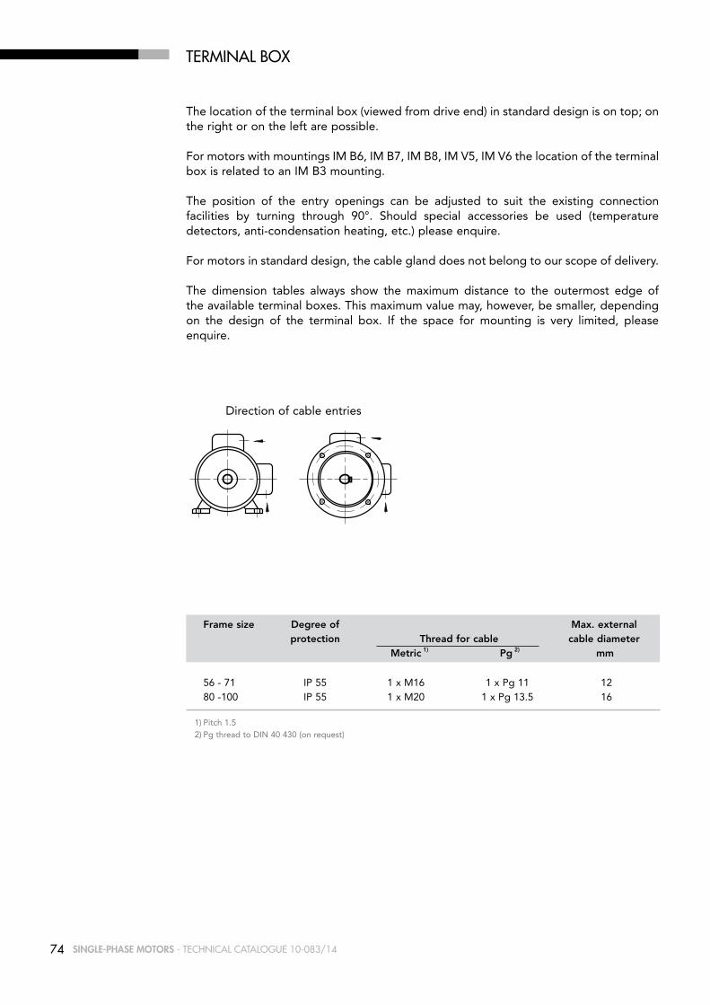
74 SINGLE-PHASE MOTORS - Technical caTalogue 10-083/14
TErmiNal BOx
The location of the terminal box (viewed from drive end) in standard design is on top; on the right or on the left are possible.
For motors with mountings IM B6, IM B7, IM B8, IM V5, IM V6 the location of the terminal box is related to an IM B3 mounting.
The position of the entry openings can be adjusted to suit the existing connection facilities by turning through 90°. Should special accessories be used (temperature detectors, anti-condensation heating, etc.) please enquire.
For motors in standard design, the cable gland does not belong to our scope of delivery.
The dimension tables always show the maximum distance to the outermost edge of the available terminal boxes. This maximum value may, however, be smaller, depending on the design of the terminal box. If the space for mounting is very limited, please enquire.
Direction of cable entries
Frame size Degree of Max. external protection Thread for cable cable diameter Metric 1) Pg 2) mm
56 - 71 IP 55 1 x M16 1 x Pg 11 12 80 -100 IP 55 1 x M20 1 x Pg 13.5 16
1) Pitch 1.52) Pg thread to DIN 40 430 (on request)

75SINGLE-PHASE MOTORS - Technical caTalogue 10-083/14
TErmiNal BOx
1) Frame size 80-100 the position of the terminal box is close to drive end
Terminal box on top
B
A
g4
h
Terminal box at the side
A
B g4
h
left 1)
B
A
g4
h
right
A
B g4
h
StanDarD DeSiGn
Frame g4 A b Material size h
56 115 120 148 Plastic UL 94 V0 63 120 120 148 Plastic UL 94 V0 71 129 120 148 Plastic UL 94 V0 80 150 135 173 Plastic UL 94 V0 90 160 135 173 Plastic UL 94 V0 100 166 135 173 Plastic UL 94 V0

76 SINGLE-PHASE MOTORS - Technical caTalogue 10-083/14
CONNECTiON DiaGramS
MAIN
MAIN
MAIN
Connection at high voltage rate
AUXILIARY
RUNNING CAPACITOR
Connection at low voltage rate
MAIN
AUXILIARY
RUNNING CAPACITOR
N
L
N
L
SERIES AMD
MAINMAIN
MAIN
N
L
AUXILIARY
MAIN
SExx
CAPACITORSTARTING
Connection at high voltage rate
CAPACITORRUNNING
Connection at low voltage rate
CAPACITORRUNNING
CAPACITORSTARTING
SExx
AUXILIARY
N
L
SERIES AMDE
for connection of starting capacitorSExx - electronic device
AUXILIARY
RUNNING CAPACITOR
MAIN
N
LA
AUXILIARY
MAIN
SExx
CAPACITORSTARTING
CAPACITORRUNNING
LI
N
SERIES AMM
for connection of starting capacitorSExx - electronic device
AUXILIARY
RUNNING CAPACITOR
MAIN
N
LA
AUXILIARY
MAIN
SExx
CAPACITORSTARTING
CAPACITORRUNNING
LI
N
SERIES AMME
Single-phase motors AMM and AMME series are designed for single-rated voltage; motors AMD and AMDE series for dual voltage. The windings (main and auxiliary winding) are connected to the capacitor supplied with the motor.
The direction of rotation can be reversed by inverting the winding ends as follows:
- main winding for motors with one supply voltage- auxiliary winding for dual voltage motors

77SINGLE-PHASE MOTORS - Technical caTalogue 10-083/14
ElECTrONiC STarTiNG DEViCE (SE xx)
Single-phase motors with one single capacitor generally have lower starting torques than the full load torque. When higher starting torques are required, the motor is equipped with an additional starting capacitor. It is connected by the electronic starting device (SE XX) in the moment of starting and disconnected automatically proximate to the pull-out torque (see figure). At this point the torque characteristic for the running capacitor (characteristic 2) applies again.
Characteristic 1 is not reversible. The starting capacitor is reconnected only when restarting the motor. In case of overload, characteristic 2 has to be applied.
Time between stop and restart of the motor must be higher than 15 s.
\\NTLAFERTSEGNI\SMRI\catalogo SMRI\catalogo monofase\curv-car monofase.dwg
0 0N
N
n
2
1
M
n
n
Nm

78 SINGLE-PHASE MOTORS - Technical caTalogue 10-083/14
1 Shaft protection 2 Dust seal drive end 3 Endshield drive end 4 Bearing drive end 5 Stator frame 6 Starter 7 Fixing device capacitor 8 Gasket terminal box 9 Terminal box
PART DESCRIPTION
In enquires and orders for spare parts please state always:
Designation of spare part, motor type, mounting arrangement, motor serial number (Product No. (E-No.) when available)
Enquires and orders cannot be handled without these data.
25
16
26
1
11
28
27
29
30
10
922
23
24
2
3
4
8
6
5
7
21
20
19
18
17
12
13
14
15
SParE ParTS
10 Fixing screw terminal box 11 Terminal box lid 12 Fixing screw terminal box lid 13 Gasket terminal box lid 14 Capacitor 15 Connecting block 16 Blank gland plug 17 Key 18 Rotor complete 19 Bearing non-drive end 20 Pre-load washer 21 Endshield non-drive end 22 Fan cover 23 Fixing screw fan cover 24 Fan 25 Fixing bolt endshield non-drive end 26 Fixing bolt endshield drive end 27 Fixing bolt motor feet 28 Motor feet 29 Fixing washer motor feet 30 Fixing nut motor feet

79SINGLE-PHASE MOTORS - Technical caTalogue 10-083/14
TYPE DESiGNaTiON
Apart from other information, it is necessary to specify the exact type designation in all enquiries, when ordering spare parts or replacement motors or when asking for documentary information.
The type designation of our motors comprises 8 points of reference, each of which may consist of several letters and/or numerals. The meaning of each symbol can be seen from the following table. For motors not included in our standard range, special symbols may be used which are not listed here.
Examples
Ref. Meaning Description of symbols used for our motorspoint
1 Type of motor A Asynchronous motor
2 Cooling M Surface cooled with external fan, cooling fins
3 Type of motor M Single-phase motor ME Single-phase motor with starting capacitor D Single-phase dual-voltage motor DE Single-phase dual-voltage motor with starting capacitor
4 Shaft centre height 56, 63, 71, 80, 90, 100
5 Frame length Z S Mechanical dimension (short) M Mechanical dimension (medium) L Mechanical dimension (long)
6 Mechanical A design and B output value C D
7 Frame material A Aluminium frame
8 Number of poles 2 4 6

80 SINGLE-PHASE MOTORS - Technical caTalogue 10-083/14
SiNGlE-PHaSE mOTOrS
for mainS VoltaGe230 V - 50 HZ
DESiGNED fOr raNGE Of raTED VOlTaGE220-240 V ± 5% - 50 Hz
MN η cos ϕ IN IA/IN MA/MN MK/MN
Type kW HP min-1 Nm 100% 230V 220-240V 10-3 kgm2 kg
3000 min-1 (2 poles)
AMM 56z AA 2 0.12 0.16 2600 0.4 47 0.90 1.2 1.3 1.3 1.3 1.8 0.09 3 AMM 63z AA 2 0.18 0.25 2710 0.6 58.5 0.98 1.2 1.3 3 1.2 1.8 0.14 5 AMM 63z bA 2 0.25 0.33 2760 0.9 68.6 0.95 1.7 1.9 3.2 1 1.6 0.18 5.5 AMM 71z AA 2 0.37 0.50 2780 1.3 57.6 0.89 3.1 3.3 3.1 0.8 1.9 0.41 7.1 AMM 71z bA 2 0.55 0.75 2740 1.9 69 0.89 3.9 4.1 3.5 0.7 1.7 0.55 8.5 AMM 80z AA 2 0.75 1 2800 2.6 65 0.95 5.3 5.5 4.1 0.6 2 1.05 11.4 AMM 80z bA 2 1.1 1.5 2730 3.8 74 0.97 6.5 6.6 3.6 0.5 1.6 1.08 11.8 AMM 90S AA 2 1.1 1.5 2830 3.7 68 0.94 7.5 8 4 0.4 2 1.62 15.3 AMM 90L bA 2 1.5 2 2835 5.1 73 0.90 9.3 9.6 3.9 0.5 2.1 1.87 17.3 AMM 90L CA 2 1.8 2.5 2790 6.2 73 0.99 10.8 11.2 4 0.6 2 2.09 18.7 AMM 90L DA 2 2.2 1) 3 1) 2770 7.6 73 0.90 14.6 15.4 4.3 0.2 1.8 2.11 19.3 AMM 100L AA 2 2.2 3 2795 7.5 75 0.98 12.8 13.1 4.3 0.4 1.5 4.05 24.5
1500 min-1 (4 poles) AMM 56z AA 4 0.09 0.12 1340 0.6 45 0.89 1 1.1 1.9 0.5 1.2 0.14 3.5 AMM 63z AA 4 0.12 0.16 1385 0.8 50 0.97 1 1.1 2.8 0.7 1.5 0.27 4.5 AMM 63z bA 4 0.18 0.25 1280 1.3 50 0.97 1.6 1.7 2 0.8 1.2 0.34 4.9 AMM 71z AA 4 0.25 0.33 1270 1.9 52.1 0.89 2.5 2.7 2.4 0.7 1.5 0.82 7.2 AMM 71z bA 4 0.37 0.50 1370 2.6 62 0.88 2.8 3.1 2.9 0.8 1.2 1.08 8.5 AMM 80z AA 4 0.37 0.50 1390 2.5 60 0.96 2.8 2.9 3.2 0.5 1.9 2 9.8 AMM 80z bA 4 0.55 0.75 1390 3.8 67 0.88 4 4.2 3.2 0.5 1.8 2.41 11.3 AMM 80z CA 4 0.75 1 1445 5.0 73 0.90 4.9 5.1 4.4 0.3 1.9 2.7 12.8 AMM 90L AA 4 1.1 1.5 1415 7.4 70 0.93 7.4 7.8 3.6 0.5 1.5 3.13 15.4 AMM 90L bA 4 1.5 1) 2 1) 1430 10.0 79 0.94 9 9.3 4.3 0.5 1.7 3.73 17.6 AMM 100L AA 4 1.8 2.5 1380 12.5 70 0.96 12 12.4 3.6 0.3 1.5 5.83 22.8 AMM 100L bA 4 2.2 1) 3 1) 1450 14.5 81 0.97 12.5 12.7 4.6 0.4 1.7 6 23.8
1000 min-1 (6 poles) AMM 71z AA 6 0.18 0.25 840 2.0 48.0 0.87 1.9 2 2.7 0.8 1.6 0.90 6.3 AMM 80z AA 6 0.25 0.33 900 2.7 56 0.95 2.2 2.4 2.3 0.3 1.8 2 8.8 AMM 80z bA 6 0.37 0.50 925 3.8 60 0.96 2.8 3 2.6 0.4 1.3 2.47 10 AMM 90L AA 6 0.55 0.75 950 5.5 72 0.95 3.4 3.5 3.4 0.4 1.2 5.2 16.5 AMM 90L bA 6 0.75 1 890 8.0 71 0.96 4.8 4.9 3.2 0.5 1.5 5.85 18 AMM 100L AA 6 1.1 1.5 950 11.1 69 0.96 7.1 7.7 2.9 0.2 1.3 6.73 19 AMM 100L bA 6 1.5 1) 2 1) 870 16.5 66 0.98 10 10.2 2.5 0.4 1.4 9.43 22.5
1) Temperature rise to class F

81SINGLE-PHASE MOTORS - Technical caTalogue 10-083/14
SiNGlE-PHaSE mOTOrS WiTH STarTiNG CaPaCiTOr
for mainS VoltaGe230 V - 50 HZ
DESiGNED fOr raNGE Of raTED VOlTaGE220-240 V ± 5% - 50 Hz
MN η cos ϕ IN IA/IN MA/MN MK/MN
Type kW HP min-1 Nm 100% 230V 220-240V 10-3 kgm2 kg
3000 min-1 (2 poles)
AMME 63z AA 2 0.12 0.16 2810 0.4 67.1 0.90 0.9 1 2.5 1.9 1.5 0.11 4.5 AMME 63z bA 2 0.18 0.25 2800 0.6 58.5 0.98 1.2 1.3 3 1.6 1.8 0.14 5 AMME 63z CA 2 0.25 0.33 2760 0.9 68.6 0.95 1.7 1.9 3.2 1.7 1.6 0.18 5.5 AMME 71z AA 2 0.37 0.50 2780 1.3 57.6 0.89 3.1 3.3 3.1 2.5 1.9 0.41 7.1 AMME 71z bA 2 0.55 0.75 2740 1.9 69 0.89 3.9 4.1 3.5 1.9 1.7 0.55 8.5 AMME 80z AA 2 0.75 1 2800 2.6 65 0.95 5.3 5.5 5.3 2.9 2 1.05 11.4 AMME 80z bA 2 1.1 1.5 2730 3.8 74 0.97 6.5 6.6 4 2.9 1.6 1.08 11.8 AMME 90S AA 2 1.1 1.5 2830 3.7 68 0.94 7.5 8 5.2 2.4 2 1.62 15.3 AMME 90L bA 2 1.5 2 2835 5.1 73 0.90 9.3 9.6 5.1 2.5 2.1 1.87 17.3 AMME 90L CA 2 1.8 2.5 2790 6.2 73 0.99 10.8 11.2 3.7 1.6 2.0 2.09 18.7 AMME 90L DA 2 2.2 1) 3 1) 2770 7.6 73 0.90 14.6 15.4 4 1.8 1.8 2.11 19.3 AMME 100L AA 2 2.2 3 2795 7.5 75 0.98 12.8 13.1 4.3 1.8 1.8 4.05 24.5
1500 min-1 (4 poles) AMME 63z AA 4 0.12 0.16 1385 0.8 50 0.97 1 1.1 2.8 1.2 1.5 0.27 4.5 AMME 63z bA 4 0.18 0.25 1280 1.3 50 0.97 1.6 1.7 2 1.9 1.2 0.34 4.9 AMME 71z AA 4 0.25 0.33 1270 1.9 52.1 0.89 2.5 2.7 2.4 3 1.5 0.82 7.2 AMME 71z bA 4 0.29 0.39 1275 2.2 56.1 0.95 2.4 2.5 4 3 1.6 0.95 7.8 AMME 71z CA 4 0.37 0.50 1370 2.6 62 0.88 2.8 3.1 2.9 2.5 1.2 1.08 8.5 AMME 80z AA 4 0.37 0.50 1390 2.5 60 0.96 2.8 2.9 2.5 1.8 1.9 2 9.8 AMME 80z bA 4 0.55 0.75 1390 3.8 67 0.88 4 4.2 3.3 2.3 1.8 2.41 11.3 AMME 80z CA 4 0.75 1 1445 5.0 73 0.90 4.9 5.1 5.4 2.4 2 2.7 12.8 AMME 90L AA 4 1.1 1.5 1415 7.4 70 0.93 7.4 7.8 4.8 2 1.5 3.13 15.4 AMME 90L bA 4 1.5 1) 2 1) 1430 10.0 79 0.94 9 9.3 4.7 1.8 1.7 3.73 17.6 AMME 100L AA 4 1.8 2.5 1380 12.5 70 0.96 12 12.4 3.2 1.5 1.5 5.83 22.8 AMME 100L bA 4 2.2 1) 3 1) 1450 14.5 81 0.97 12.5 12.7 4.6 1 1.7 6 23.8
1000 min-1 (6 poles)
AMME 71z AA 6 0.15 0.20 865 1.7 43 0.83 1.8 1.9 1.8 1.9 1.2 1.24 8 AMME 80z AA 6 0.25 0.33 900 2.7 56 0.95 2.2 2.4 2.3 1.3 1.8 2 8.8 AMME 80z bA 6 0.37 0.50 925 3.8 60 0.96 2.8 3 2.7 2 1.3 2.47 10 AMME 90L AA 6 0.55 0.75 950 5.5 72 0.95 3.4 3.5 3.8 2.5 1.2 5.2 16.5 AMME 90L bA 6 0.75 1 890 8.0 71 0.96 4.8 4.9 3 3.4 1.5 5.85 18 AMME 100L AA 6 1.1 1.5 950 11.1 69 0.96 7.1 7.7 2.4 1.4 1.3 6.73 19 AMME 100L bA 6 1.5 1) 2 1) 870 16.5 66 0.98 10 10.2 2.5 2 1.4 9.43 22.5
1) Temperature rise to class F

82 SINGLE-PHASE MOTORS - Technical caTalogue 10-083/14
SiNGlE-PHaSE DUal-VOlTaGE mOTOrS
for mainS VoltaGe115-230 V - 50 HZ
MN η cos ϕ IN IA/IN MA/MN MK/MN
Type kW HP min-1 Nm 100% 115-230V 10-3 kgm2 kg
3000 min-1 (2 poles)
AMD 63z AA 2 0.11 0.15 2760 0.4 52 0.93 2-1 2.8 0.6 1.5 0.11 4.5 AMD 63z bA 2 0.18 0.25 2800 0.6 55 0.98 2.9-1.45 3 0.5 1.6 0.14 5 AMD 63z CA 2 0.24 0.32 2815 0.8 56 0.98 3.8-1.9 3.1 0.6 1.8 0.18 5.5 AMD 71z AA 2 0.37 0.50 2730 1.3 55 0.90 6.6-3.3 3.3 0.9 2 0.41 7.1 AMD 71z bA 2 0.55 0.75 2840 1.8 64 0.94 8-4 4.2 0.5 1.9 0.55 8.5 AMD 80z AA 2 0.75 1 2800 2.6 60 0.78 13.8-7 3.5 0.4 2.1 1.05 11.4 AMD 80z bA 2 1.1 1.5 2770 3.8 72 0.93 14.2-7.2 3.5 0.5 1.6 1.08 11.8 AMD 90S AA 2 1.1 1.5 2815 3.7 70 0.78 17.5-8.8 3.8 0.4 1.9 1.62 15.3 AMD 90L bA 2 1.5 2 2800 5.1 69 0.87 22-11 3.6 0.4 1.8 1.87 17.3 AMD 90L CA 2 1.8 2.5 2810 6.1 70 0.89 25-12.5 3.7 0.3 1.9 2.09 18.7 AMD 90L DA 2 2.2 1) 3 1) 2880 7.3 76 0.93 27.2-13.6 5 0.3 1.9 2.10 19.3 AMD 100L AA 2 2.2 3 2810 7.5 75 0.92 28-14 4.6 0.2 1.8 4.05 24.5
1500 min-1 (4 poles) AMD 63z AA 4 0.11 0.15 1370 0.8 53 0.89 2.2-1.1 2 0.8 1.6 0.27 4.5 AMD 63z bA 4 0.18 0.25 1340 1.3 51 0.9 3.3-1.7 1.9 0.6 1.3 0.34 4.9 AMD 71z AA 4 0.24 0.32 1300 1.8 51 0.81 5.1-2.55 2.5 0.7 1.4 0.82 7.2 AMD 71z bA 4 0.29 0.39 1340 2.1 61 0.84 4.9-2.45 2.6 0.6 1.6 0.95 7.8 AMD 71z CA 4 0.37 0.5 1370 2.6 58 0.85 6.5-3.25 3.4 0.5 1.5 1.08 8.5 AMD 80z AA 4 0.37 0.5 1375 2.6 54 0.94 6.3-3.15 2.5 0.7 1.5 2 9.8 AMD 80z bA 4 0.55 0.75 1360 3.9 66 0.84 8.6-4.3 3.4 0.6 1.7 2.41 11.3 AMD 80z CA 4 0.75 1 1435 5.0 62 0.91 11.5-5.75 4.1 0.4 1.9 2.7 12.8 AMD 90L AA 4 1.1 1.5 1425 7.4 69 0.81 17-8.5 3.9 0.3 1.9 3.13 15.4 AMD 90L bA 4 1.5 1) 2 1) 1415 10.1 72 0.88 20.5-10.25 3.4 0.3 1.4 3.73 17.6 AMD 100L AA 4 1.8 2.5 1430 12.0 70 0.86 26-13 3.2 0.3 1.6 5.83 22.8 AMD 100L bA 4 2.2 1) 3 1) 1440 14.6 72 0.86 31-15.5 3.2 0.2 1.3 6 23.8
1000 min-1 (6 poles)
AMD 71z AA 6 0.15 0.20 910 1.6 58 0.80 2.8-1.4 2.2 0.5 1.4 1.24 8 AMD 80z AA 6 0.25 0.33 930 2.6 61 0.85 4.2-2.1 2.3 0.4 1.2 2 8.8 AMD 80z bA 6 0.37 0.50 940 3.8 61 0.82 6.4-3.2 2.9 0.4 1.6 2.47 10 AMD 90L AA 6 0.55 0.75 950 5.5 68 0.83 8.5-4.25 2.7 0.6 1.3 5.2 16.5 AMD 90L bA 6 0.75 1 950 7.5 58 0.79 14.2-7.1 3 0.4 1.6 5.85 18 AMD 100L AA 6 1.1 1.5 935 11.2 72 0.88 15-7.5 3.1 0.3 1.4 6.73 19 AMD 100L bA 6 1.5 1) 2 1) 890 16.1 74 0.98 18-9 2.9 0.5 1.4 9.43 22.5
1) Temperature rise to class F

83SINGLE-PHASE MOTORS - Technical caTalogue 10-083/14
SiNGlE-PHaSE DUal-VOlTaGE mOTOrS WiTH STarTiNG CaPaCiTOr
MN η cos ϕ IN IA/IN MA/MN MK/MN
Type kW HP min-1 Nm 100% 115-230V 10-3 kgm2 kg
3000 min-1 (2 poles)
AMDE 63z AA 2 0.11 0.15 2760 0.4 52 0.93 2-1 2.8 1.9 1.5 0.11 4.5 AMDE 63z bA 2 0.18 0.25 2800 0.6 55 0.98 2.9-1.45 3 1.6 1.6 0.14 5 AMDE 63z CA 2 0.24 0.32 2815 0.8 56 0.98 3.8-1.9 3.1 1.8 1.8 0.18 5.5 AMDE 71z AA 2 0.37 0.50 2730 1.3 55 0.90 6.6-3.3 3.3 2.5 2 0.41 7.1 AMDE 71z bA 2 0.55 0.75 2840 1.8 64 0.94 8-4 4.2 1.3 2 0.55 8.5 AMDE 80z AA 2 0.75 1 2800 2.6 60 0.78 13.8-7 3.5 1.3 2.2 1.05 11.4 AMDE 80z bA 2 1.1 1.5 2770 3.8 72 0.93 14.2-7.2 3.5 1.4 1.6 1.08 11.8 AMDE 90S AA 2 1.1 1.5 2815 3.7 70 0.78 17.5-8.75 3.8 2.6 1.9 1.62 15.3 AMDE 90L bA 2 1.5 2 2800 5.1 69 0.87 22-11 3.6 2.6 1.8 1.87 17.3 AMDE 90L CA 2 1.8 2.5 2810 6.1 70 0.89 25-12.5 3.7 1.6 1.9 2.09 18.7 AMDE 90L DA 2 2.2 3 2880 7.3 76 0.93 27.2-13.6 5 2.5 1.9 2.10 19.3 AMDE 100L AA 2 2.2 1) 3 1) 2810 7.5 75 0.92 28-14 4.6 1.8 1.8 4.05 24.5
1500 min-1 (4 poles) AMDE 63z AA 4 0.11 0.15 1370 0.8 53 0.89 2.2-1.1 2 1.9 1.6 0.27 4.5 AMDE 63z bA 4 0.18 0.25 1340 1.3 51 0.9 3.3-1.7 1.9 1 1.3 0.34 4.9 AMDE 71z AA 4 0.24 0.32 1300 1.8 51 0.81 5.1-2.55 2.5 2.3 1.4 0.82 7.2 AMDE 71z bA 4 0.29 0.39 1340 2.1 61 0.84 4.9-2.45 2.6 1.7 1.6 0.95 7.8 AMDE 71z CA 4 0.37 0.5 1370 2.6 58 0.85 6.5-3.25 3.4 1.4 1.5 1.08 8.5 AMDE 80z AA 4 0.37 0.5 1375 2.6 54 0.94 6.3-3.15 2.5 1.8 1.5 2 9.8 AMDE 80z bA 4 0.55 0.75 1360 3.9 66 0.84 8.6-4.3 3.4 2.1 1.7 2.41 11.3 AMDE 80z CA 4 0.75 1 1435 5.0 62 0.91 11.5-5.75 4.1 2 1.9 2.7 12.8 AMDE 90L AA 4 1.1 1.5 1425 7.4 69 0.81 17-8.5 3.9 2 1.9 3.13 15.4 AMDE 90L bA 4 1.5 1) 2 1) 1415 10.1 72 0.88 20.5-10.25 3.4 2 1.4 3.73 17.6 AMDE 100L AA 4 1.8 2.5 1430 12.0 70 0.86 26-13 3.2 2.1 1.6 5.83 22.8 AMDE 100L bA 4 2.2 1) 3 1) 1440 14.6 72 0.86 31-15.5 3.2 1.5 1.3 6 23.8
1000 min-1 (6 poles)
AMDE 71z AA 6 0.15 0.20 910 1.6 58 0.80 2.8-1.4 2.2 1.9 1.4 1.24 8 AMDE 80z AA 6 0.25 0.33 930 2.6 61 0.85 4.2-2.1 2.3 1.3 1.2 2 8.8 AMDE 80z bA 6 0.37 0.50 940 3.8 61 0.82 6.4-3.2 2.9 1.9 1.6 2.47 10 AMDE 90L AA 6 0.55 0.75 950 5.5 68 0.83 8.5-4.25 2.7 3 1.3 5.2 16.5 AMDE 90L bA 6 0.75 1 950 7.5 58 0.79 14.2-7.1 3 3.4 1.6 5.85 18 AMDE 100L AA 6 1.1 1.5 935 11.2 72 0.88 15-7.5 3.1 1.9 1.4 6.73 19 AMDE 100L bA 6 1.5 1) 2 1) 890 16.1 74 0.98 18-9 2.9 2 1.4 9.43 22.5
1) Temperature rise to class F
for mainS VoltaGe115-230V - 50 HZ

84 SINGLE-PHASE MOTORS - Technical caTalogue 10-083/14
SiNGlE-PHaSE framE SizE 56 - 100 im B3
GD
GA
C
K
LB
BB
B
BA
E
AL
L
AA
CA
EA
K1
A
AF AD
DB
D
LC
DA
AC
HD
AD
HAH
AB
HC
1) Clearance hole for screw2) Maximum dimension3) Centering holes in shaft extensions to DIN 332 part 2
IEC H A b C K 1) Ab bb CA AD 2) HD 2) AC HC HA K1
56 56 90 71 36 6 107 86 64 116 172 110 109 8 9 63 63 100 80 40 7 120 100 72 120 183 124 120 8 11 71 71 112 90 45 8 135 108 83 134 205 139 142 9 11 80 80 125 100 50 10 153 125 89 150 230 160 162 9.5 14 90S 90 140 100 56 10 170 150 116 160 250 180 181 11 15 90L 90 140 125 56 10 170 150 91 160 250 180 181 11 15 100 100 160 140 63 11 192 166 110 166 266 196 198 12 17
IEC L Lb LC AL AF bA AA D/DA E/EA F/FA GD GA/GC Db 3)
56 188 168 211 61 147 27 27 9 j6 20 3 3 10.2 M3
63 211 188 238 63 147 29 30 11 j6 23 4 4 12.5 M4 71 246 216 278 69 147 28 31 14 j6 30 5 5 16 M5 80 272 232 319 79 173 28.5 34.5 19 j6 40 6 6 21.5 M6 90S 317 267 372 85 173 28/53 37 24 j6 50 8 7 27 M8 90L 317 267 372 85 173 28/53 37 24 j6 50 8 7 27 M8 100 366 306 433 91 173 38 44 28 j6 60 8 7 31 M10

85SINGLE-PHASE MOTORS - Technical caTalogue 10-083/14
SiNGlE-PHaSE framE SizE 56 - 100 im B5, im B35, im V1
LB
E
AL
L
EA
E
LA
T
GD
GA
AF
F
DB
P N
D
DA
AC M
S
LC
K
C B
K1
C A A
AD
LB
BB AB
AABA
AD
HD
HAH
IEC AD 2) HD 2) AC HA K1 L Lb LC AL AF D/DA E/EA F/FA GD GA/GC Db 3)
56 116 172 110 8 9 188 168 211 61 147 9 j6 20 3 3 10.2 M3 63 120 183 124 8 11 211 188 238 63 147 11 j6 23 4 4 12.5 M4 71 134 205 139 9 11 246 216 278 69 147 14 j6 30 5 5 16 M5 80 150 230 160 9.5 14 272 232 319 79 173 19 j6 40 6 6 21.5 M6 90S 160 250 180 11 15 317 267 372 85 173 24 j6 50 8 7 27 M8 90L 160 250 180 11 15 317 267 372 85 173 24 j6 50 8 7 27 M8 100 166 266 196 12 17 366 306 433 91 173 28 j6 60 8 7 31 M10 1) Clearance hole for screw2) Maximum dimension3) Centering holes in shaft extensions to DIN 332 part 2
IEC M N P T LA S H A b C K 1) CA bb AA Ab bA
56 100 80 120 2.5 7 7 56 90 71 36 6 64 86 27 107 27 63 115 95 140 3 8 9.5 63 100 80 40 7 72 100 30 120 29 71 130 110 160 3.5 10 9.5 71 112 90 45 8 83 108 31 135 28 80 165 130 200 3.5 10 11.5 80 125 100 50 10 89 125 34.5 153 28.5 90S 165 130 200 3.5 12 11.5 90 140 100 56 10 116 150 37 170 28/5390L 165 130 200 3.5 12 11.5 90 140 125 56 10 91 150 37 170 28/53 100 215 180 250 4 14 14 100 160 140 63 11 110 166 44 192 38

86 SINGLE-PHASE MOTORS - Technical caTalogue 10-083/14
SiNGlE-PHaSE framE SizE 56 - 100 im B14, im B34
E
LA
LB
LC
E
T
AL
L
EA
GD
GA
AF
DB
F
P N
D
DA
AC
M
S
K
C B C A
K1A
AB
AA
LB
BB
AD
BA
HD
AD
H HA
HC
IEC GD GA/GC Db 3) H A b C K 1) Ab bb AA bA CA AD 2) HD 2) AC HC HA K1
56 3 10.2 M3 56 90 71 36 6 107 86 27 27 64 116 172 110 109 8 9 63 4 12.5 M4 63 100 80 40 7 120 100 30 29 72 120 183 124 120 8 11
71 5 16 M5 71 112 90 45 8 135 108 31 28 83 134 205 139 142 9 11
80 6 21.5 M6 80 125 100 50 10 153 125 34.5 28.5 89 150 230 160 162 9.5 14
90S 7 27 M8 90 140 100 56 10 170 150 37 28/53 116 160 250 180 181 11 1590L 7 27 M8 90 140 125 56 10 170 150 37 28/53 91 160 250 180 181 11 15
100 7 31 M10 100 160 140 63 11 192 166 44 38 110 166 266 196 198 12 17 1) Clearance hole for screw2) Maximum dimension3) Centering holes in shaft extensions to DIN 332 part 2
IEC P N LA M T S P N LA M T S L Lb LC AL AF D/DA E/EA F/FA
56 80 50 8 65 2.5 M5 105 70 8 85 2.5 M6 188 168 211 61 147 9j6 20 3
63 90 60 8 75 2.5 M5 120 80 8 100 2.5 M6 211 188 238 63 147 11j6 23 4
71 105 70 8 85 2.5 M6 140 95 8 115 3 M8 246 216 278 69 147 14j6 30 5
80 120 80 9 100 3 M6 160 110 8.5 130 3.5 M8 272 232 319 79 173 19j6 40 6
90S 140 95 9 115 3 M8 160 110 9 130 3.5 M8 317 267 372 85 173 24j6 50 8 90L 140 95 9 115 3 M8 160 110 9 130 3.5 M8 317 267 372 85 173 24j6 50 8
100 160 110 10 130 3.5 M8 200 130 12 165 3.5 M10 366 306 433 91 173 28j6 60 8
SMALL FLANGE LARGE FLANGE

87BRAKE MOTORS - Technical caTalogue 10-083/14
BraKE mOTOrS

88 BRAKE MOTORS - Technical caTalogue 10-083/14
tHree-PHaSe BraKe motor witH HiGH-torQUe D.C. BraKe
Frame sizes: 63 ... 160Output range: 0.12 ... 22kW Polarity: 2, 4, 6, 8 (pole-changing on request)Insulation class FStandard degree of protection: IP 54 (IP 55 on request) for frame size ≤ 132, IP 55 for frame size 160Double braking surface Asbestos-free friction surfaces Electromagnetic spring-loaded brake with release in case of power supply interruption Standard rectifier supply: 230 V - 50/60 Hz (others on request) Progressive and noiseless brakingHigh braking torque (Mb >1,5 MN) Step adjustment braking torque (~ 33%; 67%;100% Mb max)Fast acting rectifier available on request only for rectifier supply 230V 50/60Hz (sizes 63 ...112)Special execution for wind generator available on request (continuous braking torque adjustment in the range 30% Mb max … 100% Mb max), antisticking execution, corrosion resistance execution, reduced braking torque value, reduced range braking torque regulation, …)cURus approval on requestEfficiency class conform to Energy cURus on requestAvailable with a large number of options (i.e. encoder, axial independent cooling fan, hand release lever, special brake designs, flywheel, …) High number of starts/hour
Typical applications: Automation requiring a smooth intervention, transfer machinery, packaging machinery, gearmotors.
Mb1) [Nm] brake absorption [A] on
brake Motor braking spring number Air gap dc side @ rectifier size size 2 3 4 6 9 [mm] input 230V 50/60Hz
12 MV 63 1.8 3.5 0.25 …0.5 0.1 A 12 MV 71 1.8 3.5 0.25 …0.5 0.1 A 53 MV 2.5 5 7.5 0.25 …0.5 0.14 A 13 MV 80 2.5 5 7.5 0.25 …0.5 0.14 A 04 MV 5 10 15 0.3 …0.55 0.17 A 14 MV 90 5 10 15 0.3 …0.55 0.17 A 05 MV 13 26 40 0.3 …0.55 0.23 A 15 MV 100 13 26 40 0.3 …0.55 0.23 A 56S MV 25 50 75 0.35 …0.6 0.34 A 15 MV 112 13 26 40 0.3 …0.55 0.23 A 56S MV 25 50 75 0.35 …0.6 0.34 A 16S MV 132 25 50 75 0.35 …0.6 0.54 A 07 MV 50 100 150 0.4 …0.8 0.7 A 17 MV 160 50 100 150 0.4 …0.8 0.7 A 08 MV 85 170 250 0.5 …0.9 1.2 A
1) Rated values ± 20% For delays of release/braking consult us For max friction work for each braking consult us
taBle of tHe main BraKe featUreS
TECHNiCal DESCriPTiON - amBY SEriES

89BRAKE MOTORS - Technical caTalogue 10-083/14
1
41/1
3
2
4
5
22
23
24
25
8
9
10
11
12
1314
16
7
41/2
41/3
20
19
32
33
39/2
21
2627
28
3031
35
36
38
37
37
40
36
35
39/3
39/1
39/3
33
17
15
18
6
34
29
34
SParE ParTS fOr amBY mOTOrS
1 Shaft protection 2 Dust seal drive end 3 Endshield drive end 4 Pre-load washer 5 Bearing drive end 6 Stator frame 7 Motor terminal board 8 Fixing screw motor terminal board 9 Gasket terminal box 10 Terminal box 11 Fixing screw terminal box 12 Gasket terminal box lid 13 Terminal box lid 14 Fixing screw terminal box lid 15 Blank gland plug 16 Blank gland plug 17 Brake terminal board (for sizes 63 … 112a)) 18 Rectifier 19 Motor key 20 Rotor complete 21 Brake key 22 Circlip 23 Bearing non-drive end 24 Endshield non-drive endb)
25 Tie rod 26 Dust seal (for IP55 only) 27 Circlip 28 Brake hub 29 Anti-vibration spring/O-ring 30 Circlip 31 Brake disk 32 Brake gasket (for IP55 only) 33 Preassembled part of the brake (electromagnet, brake anchor, braking springs, fixing screws, guiding pipes, fastening nuts)
34 Dust seal (for IP55 only) 35 Fan 36 Circlip (only for sizes 100 and 112) 37 Fixing screw fan cover 38 Fan cover 39 Hand release: 39/1 hand lever 39/2 releasing lever 39/3 regulation/fixing kit 40 Fan cover for hand release 41 Foot kit (1 foot): 41/1 fixing screw 41/2 foot 41/3 fixing nutc)
a) for sizes >112 brake terminal board is on the rectifier b) for sizes 63 and 71 with braking flange c) for sizes 132-160 washer and nut
PART DESCRIPTION

90 BRAKE MOTORS - Technical caTalogue 10-083/14
TECHNiCal DESCriPTiON - amBz SEriES
tHree-PHaSe BraKe motor witH HiGH-torQUe a.C. BraKe Frame sizes: 63 ... 160Output range: 0.12 ... 22kW Polarity: 2, 4, 6, 8 (pole-changing on request)Insulation class FStandard degree of protection: IP 54 (IP 55 on request) for frame size 132, IP 55 for frame size 160Double braking surface Asbestos-free friction surfaces Electromagnetic spring-loaded brake with release in case of power supply interruption Standard brake supply: 230/400V - 50Hz (others on request) with separate terminal block High braking torque (Mb > 1.5 MN) Step adjustment braking torque as standard according to table below (< 33%; 67%;100% Mb max)Special execution for wind generator available on request (continuous braking torque adjustment (in the range 30% Mb max … 100% Mb max), antisticking execution, corrosion resistance execution, reduced braking torque value, reduced range braking torque regulation, …)cURus approval on requestEfficiency class conform to Energy cURus on requestAvailable with a large number of options (i.e. encoder, axial independent cooling fan, hand release lever, special brake designs, flywheel, …) Very high number of starts/hour
Typical applications: Automation with high intervention frequency, gearmotors, lifting, handling machinery.
taBle of tHe main BraKe featUreS
brake absorption brake Motor Mb
1) [Nm] Air gap [A] size size min average max (std) [mm] @ 230/400V
12 MS/MV 63 1.8 3.5 0.25 … 0.5 0.18/0.1 12 MS/MV 71 1.8 3.5 0.25 … 0.5 0.18/0.1 53 MS/MV 2.5 5 7.5 0.25 … 0.5 0.2/0.12 13 MS/MV 80 2.5 5 7.5 0.25 … 0.5 0.2/0.12 04 MS/MV 5 10 15 0.3 … 0.55 0.28/0.16 14 MS/MV 90 5 10 15 0.3 … 0.55 0.28/0.16 05 MS/MV 13 26 40 0.3 … 0.55 0.63/0.36 15 MS/MV 100 13 26 40 0.3 … 0.55 0.63/0.36 56S MS/MV 25 50 75 0.35 … 0.6 1.2/0.68 15 MS/MV 112 13 26 40 0.3 … 0.55 0.63/0.36 56S MS/MV 25 50 75 0.35 … 0.6 1.2/0.68 16S MS/MV 132 25 50 75 0.35 … 0.6 1.2/0.68 07 MS/MV 50 100 150 0.4 … 0.8 1.5/0.87 17 MS/MV 160 50 100 150 0.4 … 0.8 1.5/0.87 08 MS/MV 85 170 250 0.5 … 0.8 1.9/1.1
1) Rated values ± 20% For delays of release/braking consult us For max friction work for each braking consult us

91BRAKE MOTORS - Technical caTalogue 10-083/14
SParE ParTS fOr amBz mOTOrS
1 Shaft protection 2 Dust seal drive end 3 Endshield drive end 4 Pre-load washer 5 Bearing drive end 6 Stator frame 7 Terminal board support (for sizes 63 … 112) 8 Fixing screw terminal board support (for sizes 63 … 112) 9 Motor terminal board 10 Fixing screw motor terminal board 11 Gasket terminal box 12 Terminal box 13 Fixing screw terminal box 14 Gasket terminal box lid 15 Terminal box lid 16 Fixing screw terminal box lid 17 Blank gland plug 18 Blank gland plug 19 Fixing screw brake terminal board (for sizes 63 … 112) 20 Brake terminal board (for sizes 63 … 112) 21 Motor key 22 Rotor complete 23 Brake key 24 Circlip 25 Bearing non-drive end 26 Endshield non-drive enda)
27 Tie rod 28 Dust seal (for IP55 only) 29 Circlip 30 Brake hub 31 Anti-vibration spring/O-ring
32 Circlip 33 Brake disk 34 Brake gasket (for IP55 only) 35 Preassembled part of the brake (electromagnet,brake anchor,braking springs, fixing screws, guiding pipes, fastening nuts, spacers) 36 Dust seal (for IP55 only) 37 Fan 38 Circlip (only for sizes 100 and 112) 39 Fixing screw fan cover 40 Fan cover 41 Hand release: 41/1 hand lever 41/2 releasing lever 41/3 regulation/fixing kit 42 fan cover for hand release 43 foot kit (1 foot): 43/1 fixing screw 43/2 foot 43/3 fixing nutb)
a) for sizes 63 and 71 with braking flange b) for size ≥ 132 washer and nut
PART DESCRIPTION

92 BRAKE MOTORS - Technical caTalogue 10-083/14
tHree-PHaSe BraKe motor witH low-torQUe D.C. BraKe witH reDUCeD oVerall DimenSionS Frame sizes: 63 … 160 Output range: 0.12 … 22 kW Polarity: 2, 4, 6, 8 (pole changing on request) Insulation class F IP 54 as standard degree of protection (IP 55 on request) Electromagnetic spring-loaded brake with release in case of power supply interruption Standard rectifier supply: 230 V - 50/60 Hz (others on request) Standard version for easy air gap adjustment (version for manual rotation of the shaft front N-end available on request for size 63 ... 132)Single braking surface Asbestos-free friction surfaces Non adjustable braking torque (Mb ≤ MN) Soft, progressive and noiseless braking Very reduced overall dimensions (similar to standard motors series AM)Increased braking torque (+50% of the catalogue value) available on requestFast acting rectifier available on request only for rectifier supply 230V 50/60HzcURus Approval on requestEfficiency class conform to Energy cURus on requestAvailable with a large range of options (i.e. encoder, axial independent cooling fan, hand release lever, …)
Typical applications: Woodworking/cutting machinery, machinery requiring long braking periods and high braking duties.
brake absorption [A] on brake Motor M
b1) Air gap dc side @ rectifier input
size size [Nm] [mm] 200V 50/60Hz
63 63 3 0.25 …0.5 0.1 A 71 71 4 0.25 …0.5 0.1 A 80 80 7 0.25 …0.5 0.16 A 90 90 7 0.25 …0.5 0.16 A 100 100 13 0.3 …0.55 0.2 A 112 13 0.3 …0.55 0.2 A 132 L 132 30 0.35 … 0.6 0.27 A 160 30 0.35 …0.6 0.27 A
1) Rated values ± 20% For delays of release/braking consult us For max friction work for each braking consult us
taBle of tHe main BraKe featUreS
TECHNiCal DESCriPTiON - amS SEriES

93BRAKE MOTORS - Technical caTalogue 10-083/14
SParE ParTS fOr amS mOTOrS fOr EaSY air GaP aDjUSTmENT 1)
*
1
2
35/2
35/1
35/3
28
27
3
4
65
7
8
1817
19
2120
22
29
30
31
32
27
24
23
25
9
10
11
12
1314
15
26
33/1
33/2
33/3
28
29
30
3234
16
AMS
1) AMS for manual rotation of the shaft from NDE available on request
PART DESCRIPTION
1 Shaft protection 2 Dust seal drive end 3 Endshield drive end 4 Pre-load washer 5 Bearing drive end 6 Stator frame 7 Motor terminal board 8 Fixing screw motor terminal board 9 Gasket terminal box 10 Terminal box 11 Fixing screw terminal box 12 Gasket terminal box lid 13 Terminal box lid 14 Fixing screw terminal box lid 15 Blank gland plug 16 Blank gland plug 17 Brake terminal board 18 Rectifier 19 Motor key 20 Rotor complete 21 Brake key 22 Circlip 23 Bearing non-drive end 24 Endshield non-drive end 25 Tie rod 26 Main contrast spring 27 Preassembled part of the brake (electromagnet, brake anchor with friction surface, braking springs, fixing screws)
28 Brake fan (with fixed washer) 29 Auxiliary contrast spring 30 Air gap adjustment/fixing screw 31 Fan cover 32 Fixing screw fan cover 33 Hand release: 33/1 hand lever 33/2 releasing lever 33/3 regulation/fixing kit 34 Fan cover for hand release 35 Foot kit (1 foot) (for sizes 71 … 132a)) 35/1 fixing screw 35/2 foot 35/3 fixing nutb)
a) for size 63 feet integral with the case b) for size 132 washer and nut

94 BRAKE MOTORS - Technical caTalogue 10-083/14
CONNECTiON DiaGramS
MAX VOLTAGE
MIN VOLTAGE
W2 U2 V2
W1U1 V1
V2U2
W1V1U1
W2
V1U1 W1
V2U2W2
W2
U1 V1 W1
U2 V2
BRAKEMOTORS
Every brake motors has got, inside the terminal box, the connection diagram both for the motor and for the brake/rectifier.For brake motors with ac brakes (AMBZ series) the connection diagram is

95BRAKE MOTORS - Technical caTalogue 10-083/14
CONNECTiON DiaGramS
V1U1 W1
V2U2W2
MIN VOLTAGE
MAX VOLTAGE
W2
U1 V1 W1
U2 V2 - +
Bra
ke
RECTIFIER
- +
Bra
ke
RECTIFIER
For AMBY 132-160
RECTIFIER
REDBR
AK
E BLACK
BLACK
BR
AK
E
RED
RECTIFIER
V1U1 W1
V2U2W2
MIN VOLTAGE
MAX VOLTAGE
W2
U1 V1 W1
U2 V2
For AMS (63 ... 160) and AMBY (63 ...112)
For brake motors with dc brake (AMS and AMBY series) required at 230/400V 50Hz, the rectifier is directly connected to the motor terminal block as follows

96 BRAKE MOTORS - Technical caTalogue 10-083/14
For AMS (63 ... 160) and AMBY (63 ...112)
For AMBY 132-160
Supplying the rectifier separately from the motor terminal block allows to reduce the delay of braking; to achieve the fast braking on AMBY132-160 it is necessary to open even the dc side of the brake coil (according to previous figure).In case of pole-changing brake motors: for motor connection see three phase motors section , the brake/rectifier has to be supplied separately.
Warning: for the correct supply of both motor and brake refer to the values written on nameplate.
Bra
ke
+-
- +STANDARD BRAKING
FAST BRAKING
V1U1 W1
V2U2W2
MIN VOLTAGE
MAX VOLTAGE
W2
U1 V1 W1
U2 V2
Bra
ke
V1U1 W1
V2U2W2
MIN VOLTAGE
MAX VOLTAGE
W2
U1 V1 W1
U2 V2
RECTIFIER
RE
D
BRAKE
BLA
CK
For all other supply value, different from 230/400V 50Hz, since the standard rectifier supply is 230V 50/60Hz, and when an inverter supply is used the rectifier has to be separately supplied according to the diagrams:
CONNECTiON DiaGramS

97BRAKE MOTORS - Technical caTalogue 10-083/14
Apart from other information, it is necessary to specify the exact type designation in all enquiries, when ordering spare parts or replacement motors or when asking for documentary information.
The type designation of our brake motors comprises 10 points of reference, each of which may consist of several letters and/or numerals. The meaning of each symbol can be seen from the following table. For motors not included in our standard range, special symbols may be used which are not listed here
Ref. Meaning Description of symbols used for our motorspoint
1 Type of motor A Asynchronous motor
2 Cooling M Surface cooled with external fan, cooling fins G1) Surface cooled without external fan, cooling fins MFV Surface cooled with forced ventilation, cooling fins
3 Type of motor blank Three-phase motors, standard efficiency IE1 code HE Three-phase motors, high efficiency IE2 code
4 Type of brake BY High-torque dc brake BZ High-torque ac brake S Low-torque dc brake
5 Shaft centre height 63, 71, 80, 90, 100, 112, 132,160
6 Frame length Z S Mechanical dimension (short) M Mechanical dimension (medium) L Mechanical dimension (long)
7 Mechanical A design and ... output power ... Z
8 Frame material A Aluminium frame 9 Number of poles 2 (pole-changing on request) 4 6 8
10 Special features R3 High resistance rotor
1) For AMBY and AMBZ type only
Example
TYPE DESiGNaTiON

98 BRAKE MOTORS - Technical caTalogue 10-083/14
IE1
STaNDarD EffiCiENCY BraKE mOTOrS - iE1EffiCiENCY lEVEl aCCOrDiNG TO iEC 60034-30;2008EffiCiENCY TESTiNG mETHOD iEC 60034-2-1;2007
IE code not applicable to motors 2, 4, 6 poles with PN < 0.75 kW. Efficiency testing method: IEC 60034-2;1996
for mainS VoltaGe400 V - 50 HZ
MN IE1 η cos ϕ IN IA/IN MA/MN MK/MN
Type kW HP min-1 Nm 50% 75% 100% 400V 380-420V
3000 min-1 (2 poles)
AM... 63z AA 2 0.18 0.25 2790 0.6 54.0 58.0 63.0 0.73 0.60 0.65 3.7 3.0 3.1 AM... 63z bA 2 0.25 0.33 2790 0.9 57.0 62.0 66.0 0.70 0.80 0.75 4.5 3.2 3.3 AM... 63z CA 2* 0.37 0.5 2800 1.3 54.0 58.0 65.0 0.70 1.20 1.25 4.6 3.4 3.4 AM... 71z AA 2 0.37 0.5 2820 1.3 58.0 64.0 70.0 0.78 1.0 1.2 4.7 3.6 3.6 AM... 71z bA 2 0.55 0.75 2830 1.9 57.0 64.0 71.0 0.77 1.5 1.6 4.8 3.2 3.3 AM... 71z CA 2* 0.75 1 2800 2.6 58.9 65.7 72.6 0.76 2.0 2.1 5.2 3.1 3.1 AM... 80z AA 2 0.75 1 2840 2.5 66.3 71.5 73.0 0.78 1.9 2.0 5.0 2.8 2.9 AM... 80z bA 2 1.1 1.5 2810 3.7 72.1 75.0 75.3 0.82 2.5 2.6 4.6 2.4 2.9 AM... 80z CA 2* 1.5 2 2825 5.1 74.7 77.5 77.8 0.83 3.3 3.4 5.0 2.9 3.3 AM... 90S AA 2 1.5 2 2830 5.1 75.6 78.7 78.6 0.82 3.4 3.5 5.0 3.1 3.0 AM... 90S bA 2* 1.8 2.5 2805 6.1 74.9 78.0 78.2 0.80 4.2 4.3 4.5 2.6 2.5 AM... 90L CA 2 2.2 3 2860 7.3 81.5 82.8 81.8 0.81 4.9 4.9 7.1 4.1 4.0 AM... 90L DA 2* 3 4 2860 10.0 78.7 81.8 82.2 0.80 6.6 6.8 7.2 3.9 3.8 AM... 100L AA 2 3 4 2860 10.0 78.9 81.4 81.5 0.85 6.4 6.7 6.0 3.1 3.3 AM... 100L bA 2* 4 5.5 2835 13.5 81.1 82.5 81.7 0.88 8.0 8.1 6.2 2.9 2.9 AM... 100L CA 2* 5.5 7.5 2865 18.3 83.7 84.6 83.3 0.86 11.1 11.3 7.2 3.5 4.1 AM... 112M AA 2 4 5.5 2880 13.3 81.9 84.0 83.5 0.82 8.4 8.7 8.0 3.4 3.6 AM... 112M bA 2* 5.5 7.5 2900 18.1 83.6 84.7 85.0 0.86 10.9 11.2 7.8 3.5 3.6 AM... 112M CA 2* 7.5 10 2900 24.7 86.7 87.8 87.1 0.87 14.3 14.8 8.7 4.0 4.0 AM... 132S YA 2 5.5 7.5 2890 18.2 83.2 84.7 85.0 0.83 11.3 11.4 6.0 2.2 2.3 AM… 132S zA 2 7.5 10 2880 24.9 85.6 86.7 86.1 0.87 14.5 14.9 6.4 2.9 3.1 AM... 132M zA 2* 9.2 12.5 2900 30.3 84.7 86.8 87.0 0.84 18.4 18.8 7.0 2.8 3.2 AM... 132M RA 2* 11 15 2880 36.5 87.1 88.1 88.0 0.85 21.3 21.7 6.9 3.2 3.8 AM... 132M TA 2* 15 20 2920 49.1 86.4 88.6 88.9 0.83 29.5 30.5 7.0 3.2 3.7 AM... 160M VA 2 11 15 2940 35.7 83.4 86.4 87.7 0.83 21.9 22.7 7.4 2.5 3.1 AM... 160M XA 2 15 20 2940 48.7 87.3 88.9 88.9 0.85 28.6 29.2 8.1 3.1 3.7 AM... 160L XA 2 18.5 25 2950 59.9 88.2 89.7 89.6 0.87 34.3 34.8 8.5 3.6 4.2 AM... 160L RA 2* 22 30 2940 71.5 88.7 90.5 90.4 0.90 39.1 39.4 8.4 3.0 3.7
* Higher output (progressive motor)
For maximum friction work per stop consult us
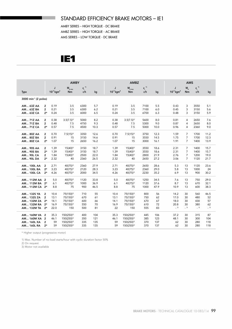
99BRAKE MOTORS - Technical caTalogue 10-083/14
STaNDarD EffiCiENCY BraKE mOTOrS – iE1amBY SEriES – HiGH TOrQUE - DC BraKE
amBz SEriES – HiGH TOrQUE - aC BraKE
amS SEriES – lOW TOrQUE - DC BraKE
J Mb max zL 1) J Mb max zL
1) J Mb zL 1)
Type 10-3 kgm2 Nm c/h kg 10-3 kgm2 Nm c/h kg 10-3 kgm2 Nm c/h kg 3000 min-1 (2 poles)
AM... 63z AA 2 AM... 63z bA 2 AM... 63z CA 2* AM... 71z AA 2 AM... 71z bA 2 AM... 71z CA 2* AM... 80z AA 2 AM... 80z bA 2 AM... 80z CA 2* AM... 90S AA 2 AM... 90S bA 2* AM... 90L CA 2 AM... 90L DA 2* AM... 100L AA 2 AM... 100L bA 2* AM... 100L CA 2* AM... 112M AA 2 AM... 112M bA 2* AM... 112M CA 2* AM... 132S YA 2 AM... 132S zA 2 AM... 132M zA 2* AM... 132M RA 2* AM... 132M TA 2* AM... 160M VA 2 AM... 160M XA 2 AM... 160L XA 2 AM... 160L RA 2*
* Higher output (progressive motor)
1) Max. Number of no-load starts/hour with cyclic duration factor 50% 2) On request 3) Motor not available
AMbY AMbz AMS
0.19 3.5 6300 5.7 0.19 3.5 7100 5.5 0.43 3 3550 5.1 0.21 3.5 6300 6.2 0.21 3.5 7100 6.0 0.45 3 3150 5.6 0.24 3.5 6000 6.5 0.24 3.5 6700 6.3 0.48 3 3150 5.9 0.38 3.5(7.5)2) 5000 8.2 0.38 3.5(7.5)2) 5600 8.0 0.81 4 2650 7.6 0.48 7.5 4750 9.3 0.48 7.5 5300 9.0 0.87 4 2650 8.0 0.57 7.5 4500 10.3 0.57 7.5 5000 10.0 0.96 4 2360 9.0 0.70 7.5(15)2) 3350 12.6 0.70 7.5(15)2) 3750 12.3 1.59 7 1700 11.2 0.91 15 3150 14.6 0.91 15 3550 14.5 1.75 7 1700 12.3 1.07 15 2650 16.2 1.07 15 3000 16.1 1.91 7 1400 13.9 1.39 15(40)2) 3150 18.7 1.39 15(40)2) 3550 18.6 2.31 7 1400 15.7 1.39 15(40)2) 3150 18.7 1.39 15(40)2) 3550 18.6 2.31 7 1400 15.7 1.84 15(40)2) 2500 22.0 1.84 15(40)2) 2800 21.9 2.76 7 1200 19.0 2.32 40 2360 26.5 2.32 40 2650 27.2 3.06 7 1120 21.7 2.71 40(75)2) 2360 27.9 2.71 40(75)2) 2650 28.6 5.3 13 1120 23.6 3.23 40(75)2) 2120 28.3 3.23 40(75)2) 2360 29.0 5.8 13 1000 24 4.26 40(75)2) 2000 34.5 4.26 40(75)2) 2230 35.2 6.9 13 900 30.2 5.0 40(75)2) 1120 33.8 5.0 40(75)2) 1250 34.5 7.6 13 750 29.0 6.1 40(75)2) 1000 36.9 6.1 40(75)2) 1120 37.6 8.7 13 670 32.1 8.8 75 900 46.5 8.8 75 1000 47.9 10.9 13 600 38.3 10.4 75(150)2) 710 55 10.4 75(150)2) 800 56 14.2 30 560 46.5 13.1 75(150)2) 670 61 13.1 75(150)2) 750 62 17.0 30 480 52 14.1 75(150)2) 600 66 14.1 75(150)2) 670 67 18.0 30 430 57 16.9 75(150)2) 550 70 16.9 75(150)2) 610 72 20.8 30 380 62 22.0 150 500 81 22 150 555 83 - 3) - 3) - 3) - 3)
35.3 150(250)2) 400 104 35.3 150(250)2) 445 106 37.2 30 315 87 46.1 150(250)2) 350 121 46.1 150(250)2) 385 123 48.1 30 300 104 59 150(250)2) 335 135 59 150(250)2) 370 137 62 30 280 118 59 150(250)2) 335 135 59 150(250)2) 370 137 62 30 280 118
IE1

100 BRAKE MOTORS - Technical caTalogue 10-083/14
IE1
STaNDarD EffiCiENCY BraKE mOTOrS - iE1EffiCiENCY lEVEl aCCOrDiNG TO iEC 60034-30;2008EffiCiENCY TESTiNG mETHOD iEC 60034-2-1;2007
IE code not applicable to motors 2, 4, 6 poles with PN < 0.75 kW. Efficiency testing method: IEC 60034-2;1996
for mainS VoltaGe400 V - 50 HZ
MN IE1 η cos ϕ IN IA/IN MA/MN MK/MN
Type kW HP min-1 Nm 50% 75% 100% 400V 380-420V 1500 min-1 (4 poles)
AM... 63z AA 4 0.12 0.16 1350 0.8 46.0 50.0 57.0 0.65 0.50 0.55 2.4 2.0 2.0 AM... 63z bA 4 0.18 0.25 1330 1.3 47.0 50.0 58.0 0.70 0.65 0.70 2.3 1.9 1.9 AM... 63z CA 4* 0.25 0.33 1360 1.8 49.0 52.5 58.0 0.74 0.85 0.90 2.7 2.2 2.1 AM... 71z AA 4 0.25 0.33 1340 1.8 55.0 59.0 64.0 0.66 0.90 1.00 3.2 1.9 2.0 AM... 71z bA 4 0.37 0.5 1370 2.6 60.0 63.0 67.0 0.67 1.20 1.25 3.3 2.2 2.2 AM... 71z CA 4* 0.55 0.75 1380 3.8 61.0 64.0 69.0 0.68 1.70 1.80 3.6 2.4 2.4 AM... 80z AA 4 0.55 0.75 1400 3.8 67.0 69.0 70.0 0.72 1.6 1.7 3.6 2.6 2.6 AM... 80z bA 4 0.75 1.0 1410 5.1 68.7 70.8 72.4 0.72 2.1 2.2 4.4 2.8 2.8 AM... 80z CA 4* 1.1 1.5 1385 7.6 73.4 75.7 75.2 0.77 2.8 2.9 4.4 2.5 2.6 AM... 90S AA 4 1.1 1.5 1400 7.5 75.8 76.0 75.4 0.78 2.7 2.9 5.2 2.5 2.8 AM... 90L bA 4 1.5 2.0 1400 10.2 77.6 77.8 77.5 0.78 3.6 3.7 5.7 2.8 3.0 AM... 90L CA 4* 1.8 2.5 1380 12.5 76.3 76.5 75.9 0.81 4.2 4.3 5.5 2.7 2.9 AM... 90L DA 4* 2.2 3.0 1400 15.0 78.3 78.5 77.9 0.77 5.3 5.5 4.8 2.9 3.2 AM... 100L AA 4 2.2 3.0 1435 14.6 76.5 79.1 79.9 0.74 5.4 5.6 5.3 2.5 2.7 AM... 100L bA 4 3.0 4.0 1425 20.1 82.0 83.0 81.6 0.78 6.8 6.9 4.6 2.4 2.5 AM... 100L CA 4* 4.0 5.5 1400 27.3 80.8 81.8 80.4 0.78 9.2 9.3 6.0 2.6 2.9 AM... 112M AA 4 4.0 5.5 1430 26.7 83.2 83.9 83.1 0.82 8.5 8.8 6.3 2.2 2.8 AM... 112M bA 4* 5.5 7.5 1430 36.7 84.1 84.8 84.0 0.83 11.4 11.7 6.5 2.2 2.9 AM... 132S zA 4 5.5 7.5 1430 36.7 87.2 87.1 86.1 0.82 11.3 11.7 5.8 3.0 3.0 AM... 132M zA 4 7.5 10 1440 49.7 87.3 87.2 86.2 0.83 15.3 15.5 6.8 3.1 3.1 AM... 132M RA 4* 9.2 12.5 1440 61.0 86.5 87.5 87.3 0.86 17.7 17.9 8.0 3.5 3.5 AM... 132M TA 4* 11.0 15 1440 72.9 83.5 83.9 84.5 0.87 21.5 22.0 8.3 3.1 3.3 AM... 160M XA 4 11 15 1460 71.9 88.5 89.3 88.7 0.80 22.4 22.7 7.5 2.5 3.1 AM... 160L XA 4 15 20 1460 98.1 89.4 90.2 89.6 0.84 28.8 29.6 7.0 2.5 3.3 AM ... 160L zA 4* 18.5 25 1460 121.8 89.9 90.7 90.1 0.84 35.4 36.0 7.6 2.5 3.3 AM ... 160L RA 4* 22 30 1460 143.9 90.4 91.2 90.6 0.86 41.0 42.0 7.8 2.4 3.2
* Higher output (progressive motor) For maximum friction work per stop consult us

101BRAKE MOTORS - Technical caTalogue 10-083/14
IE1
STaNDarD EffiCiENCY BraKE mOTOrS – iE1amBY SEriES – HiGH TOrQUE - DC BraKE
amBz SEriES – HiGH TOrQUE - aC BraKE
amS SEriES – lOW TOrQUE - DC BraKE
J Mb max zL 1) J Mb max zL
1) J Mb zL 1)
Type 10-3 kgm2 Nm c/h kg 10-3 kgm2 Nm c/h kg 10-3 kgm2 Nm c/h kg 1500 min-1 (4 poles)
AM... 63z AA 4 AM... 63z bA 4 AM... 63z CA 4* AM... 71z AA 4 AM... 71z bA 4 AM... 71z CA 4* AM... 80z AA 4 AM... 80z bA 4 AM... 80z CA 4* AM... 90S AA 4 AM... 90L bA 4 AM... 90L CA 4* AM... 90L DA 4* AM... 100L AA 4 AM... 100L bA 4 AM... 100L CA 4* AM... 112M AA 4 AM... 112M bA 4* AM... 132S zA 4 AM... 132M zA 4 AM... 132M RA 4* AM... 132M TA 4* AM... 160M XA 4 AM... 160L XA 4 AM... 160L zA 4* AM... 160L RA 4* * Higher output (progressive motor) 1) Max. Number of no-load starts/hour with cyclic duration factor 50% 2) On request 3) Motor not available
AMbY AMbz AMS
0.31 3.5 13200 5.4 0.31 3.5 15000 5.2 0.54 3 7500 4.8 0.35 3.5 12500 6.2 0.35 3.5 14000 6.0 0.59 3 7500 5.6 0.38 3.5 11800 6.3 0.38 3.5 13200 6.1 0.61 3 6700 5.7 0.70 3.5(7.5) 2) 7500 8.1 0.70 3.5(7.5) 2) 8500 7.9 1.13 4 5000 7.5 0.87 7.5 7250 9.1 0.87 7.5 8150 8.8 1.26 4 4850 7.8 1.11 7.5 6900 10.4 1.11 7.5 7800 10.1 1.50 4 4500 9.1 1.49 7.5(15) 2) 6700 12.4 1.49 7.5(15) 2) 6700 12.1 2.37 7 4250 11.0 1.93 15 6300 14.4 1.93 15 6300 14.3 2.77 7 4000 12.1 2.33 15 6000 15.7 2.33 15 6000 15.6 3.16 7 3750 13.4 2.36 15(40) 2) 5000 18.0 2.36 15(40) 2) 5650 17.9 3.28 7 3550 15.5 3.12 40 4750 21.1 3.12 40 5350 21.8 3.85 7 3350 16.3 3.69 40 4550 22.3 3.69 40 5150 23.0 4.43 7 3250 17.5 3.98 40 4300 24.8 3.98 40 4850 25.5 4.71 7 3150 20.0 4.83 40(75) 2) 4500 28.1 4.83 40(75) 2) 5050 28.8 7.4 13 2500 23.8 6.08 40(75) 2) 4250 31.1 6.08 40(75) 2) 4800 31.8 8.7 13 2350 26.8 7.24 75 4000 37.0 7.24 75 4500 38.4 9.3 13 2200 29.3 11.60 75 2500 42.4 11.60 75 2800 43.8 13.7 13 1500 34.2 14.42 75 2240 46.9 14.42 75 2500 48.3 16.5 13 1320 38.7 22.02 75(150) 2) 2000 60 22.02 75(150) 2) 2250 61 25.9 30 1180 51 28.70 75(150) 2) 1800 69 28.70 75(150) 2) 2000 70 32.6 30 1000 60 33.41 150 1500 87 33.41 150 1690 89 35.9 30 800 74 33.41 150 1500 87 33.41 150 1690 89 35.9 30 800 74 69 150(250) 2) 670 115 69 150(250) 2) 750 118 71 30 560 98 90 150(250) 2) 600 133 90 150(250) 2) 675 136 92 30 500 117 108 250 580 157 108 250 650 156 105 30 480 126 120 250 550 168 120 250 600 168 - 3) - 3) - 3) - 3)

102 BRAKE MOTORS - Technical caTalogue 10-083/14
IE1
STaNDarD EffiCiENCY BraKE mOTOrS - iE1EffiCiENCY lEVEl aCCOrDiNG TO iEC 60034-30;2008EffiCiENCY TESTiNG mETHOD iEC 60034-2-1;2007
IE code not applicable to motors 2, 4, 6 poles with PN < 0.75 kW. Efficiency testing method: IEC 60034-2;1996
for mainS VoltaGe400 V - 50 HZ
MN IE1 η cos ϕ IN IA/IN MA/MN MK/MN
Type kW HP min-1 Nm 50% 75% 100% 400V 380-420V 1000 min-1 (6 poles)
AM… 71z AA 6 0.18 0.25 880 2.0 46.0 48.0 53.0 0.60 0.85 0.9 2.2 1.6 1.6 AM… 71z bA 6 0.25 0.33 880 2.7 46.0 50.0 54.0 0.62 1.10 1.2 2.5 1.7 1.7 AM… 80z AA 6 0.37 0.5 920 3.8 47.0 58.0 60.0 0.70 1.25 1.3 2.7 1.6 2.1 AM… 80z bA 6 0.55 0.75 920 5.7 60.0 64.0 68.0 0.67 1.75 1.8 2.9 2.2 2.1 AM… 90S AA 6 0.75 1 910 7.9 70.5 72.5 71.5 0.63 2.4 2.5 2.9 1.7 1.7 AM… 90L bA 6 1.1 1.5 920 11.4 72.0 73.5 73.0 0.66 3.3 3.4 3.0 1.7 1.7 AM… 100L AA 6 1.5 2 930 15.4 73.3 75.8 75.3 0.69 4.2 4.4 3.7 1.8 2.3 AM… 100L bA 6* 1.8 2.5 940 18.3 74.6 77.1 76.6 0.67 5.1 5.3 4.2 2.4 2.8 AM… 112M AA 6 2.2 3 940 22.4 77.0 79.0 78.0 0.74 5.3 5.4 4.4 2.4 2.6 AM… 112M CA 6* 3 4 940 30.5 81.8 82.8 82.8 0.74 7.0 7.2 5.3 2.9 2.9 AM... 132S zA 6 3 4 950 30.2 79.5 81.5 81.3 0.72 7.4 7.5 4.9 2.0 2.4 AM... 132M YA 6 4 5.5 950 40.2 81.4 83.1 82.7 0.71 9.9 10.5 4.5 2.2 2.5 AM... 132M zA 6 5.5 7.5 950 55.3 82.2 83.6 83.6 0.71 13.5 13.5 4.1 2.2 2.2
AM... 160M zA 6 7.5 10 970 73.8 84.4 86.5 86.3 0.78 16.0 16.3 6.2 2.8 3.2 AM... 160L zA 6 11 15 960 109.4 88.1 88.5 87.8 0.78 23.4 24.0 6.0 2.5 3.5
* Higher output (progressive motor)
MN η cos ϕ IN IA/IN MA/MN MK/MN
Type kW HP min-1 Nm 50% 75% 100% 400V 380-420V 750 min-1 (8 poles)
AM… 71z AA 8 0.12 0.16 670 1.7 40 44 50 0.55 0.65 0.70 2.4 2.5 2.5 AM… 80z AA 8 0.25 0.33 680 3.5 40 47 51 0.62 1.1 1.2 2.2 1.8 2.0 AM… 90S AA 8 0.37 0.5 680 5.2 52 58 59 0.53 1.7 1.8 2.1 1.4 1.6 AM… 90L bA 8 0.55 0.75 680 7.7 52 58 59 0.54 2.5 2.7 2.1 1.4 1.6 AM… 100L AA 8 0.75 1.0 690 10.4 59 64 65 0.65 2.6 2.8 3.0 1.6 1.7 AM… 100L bA 8 1.1 1.5 690 15.2 59 67 68 0.62 3.9 4.0 3.0 1.9 1.6 AM… 112M AA 8 1.5 2.0 696 20.6 66 69 70 0.66 4.6 4.8 4.0 1.8 2.4 AM... 132S zA 8 2.2 3.0 710 29.6 79.3 80.5 78.8 0.64 6.40 6.6 3.4 1.7 1.7 AM... 132M zA 8 3.0 4.0 710 40.4 81.3 82.0 79.8 0.67 8.10 8.4 3.6 1.7 1.9
AM... 160M YA 8 4.0 5.5 700 54.6 84.9 84.5 84.4 0.72 9.50 9.7 4.5 1.8 2.2 AM... 160M zA 8 5.5 7.5 720 72.9 85.6 85.2 85.0 0.73 12.80 13.3 4.0 1.8 2.3
For maximum friction work per stop consult us
EffiCiENCY TESTiNG mETHOD iEC 60034-2;1996

103BRAKE MOTORS - Technical caTalogue 10-083/14
STaNDarD EffiCiENCY BraKE mOTOrS – iE1amBY SEriES – HiGH TOrQUE - DC BraKE
amBz SEriES – HiGH TOrQUE - aC BraKE
amS SEriES – lOW TOrQUE - DC BraKE
J Mb max zL 1) J Mb max zL
1) J Mb zL 1)
Type 10-3 kgm2 Nm c/h kg 10-3 kgm2 Nm c/h kg 10-3 kgm2 Nm c/h kg 1000 min-1 (6 poles)
AM... 71z AA 6 AM... 71z bA 6 AM... 80z AA 6 AM... 80z bA 6 AM... 90S AA 6 AM... 90L bA 6 AM... 100L AA 6 AM... 100L bA 6* AM... 112M AA 6 AM... 112M CA 6* AM... 132S zA 6 AM... 132M YA 6 AM... 132M zA 6 AM... 160M zA 6 AM... 160L zA 6
* Higher output (progressive motor) 1) Max. Number of no-load starts/hour with cyclic duration factor 50% 2) On request
AMbY AMbz AMS
1.14 7.5 16000 9.2 1.14 7.5 18000 8.9 1.53 4 10000 7.9 1.30 7.5 15000 9.7 1.30 7.5 16800 9.4 1.68 4 9500 8.4 1.94 7.5(15) 2) 9000 12.2 1.94 7.5(15) 2) 10100 11.9 2.82 7 6300 10.8 2.52 15 8500 14.5 2.52 15 9550 14.4 3.35 7 6000 12.2 3.07 15(40) 2) 6700 17.6 3.07 15(40) 2) 7500 17.5 4 7 5300 14.6 4.73 40 6300 22.8 4.73 40 7050 23.5 5 7 5000 18.0 6.7 40(75) 2) 5600 26.1 6.7 40(75) 2) 6300 26.8 9 13 4500 21.8 9.3 40(75) 2) 4750 30.6 9.3 40(75) 2) 5300 31.3 12 13 3750 26.3 13.2 40(75) 2) 3150 35.5 13.2 40(75) 2) 3500 36.2 16 13 2650 30.7 18.8 75 3000 52 18.8 75 3350 53 21 13 2500 43.7 22.3 75(150) 2) 2000 55 22.3 75(150) 2) 2250 56 26 30 1600 46.2 29.8 75(150) 2) 1800 60 29.8 75(150) 2) 2000 62 34 30 1500 52 39.7 150 1700 77 39.7 150 1900 80 42 30 1400 65 106 150(250) 2) 1120 119 106 150(250) 2) 1260 122 108 30 900 103 139 150(250) 2) 1000 140 139 150(250) 2) 1120 143 141 30 850 124
J Mb max zL 1) J Mb max zL
1) J Mb zL 1)
Type 10-3 kgm2 Nm c/h kg 10-3 kgm2 Nm c/h kg 10-3 kgm2 Nm c/h kg 750 min-1 (8 poles)
AM... 71z AA 8 AM... 80z AA 8 AM... 90S AA 8 AM... 90L bA 8 AM... 100L AA 8 AM... 100L bA 8 AM... 112M AA 8 AM... 132S zA 8 AM... 132M zA 8 AM... 160M YA 8 AM... 160M zA 8 AM... 160L zA 8
1) Max. Number of no-load starts/hour with cyclic duration factor 50% 2) On request
AMbY AMbz AMS
0.87 7.5 18000 9.1 0.87 7.5 20250 8.8 1.26 4 15000 7.8 1.94 7.5(15) 2) 15000 12.2 1.94 7.5(15) 2) 16750 11.9 2.82 7 11200 10.8 3.07 15(40) 2) 8000 17.4 3.07 15(40) 2) 9000 17.3 4.00 7 6300 14.4 4.54 15(40) 2) 7500 21.0 4.54 15(40) 2) 8400 20.9 5.5 7 6000 18.0 6.7 40(75) 2) 6700 26.2 6.7 40(75) 2) 7550 26.9 9.3 13 5000 21.9 9.3 40(75) 2) 6000 31.2 9.3 40(75) 2) 6750 31.9 11.9 13 4500 26.9 15.7 40(75) 2) 3550 44.5 15.7 40(75) 2) 4000 45.2 18.3 13 3150 39.7 29.8 75(150) 2) 2500 63 29.8 75(150) 2) 2800 65 33.7 30 2000 55 39.7 150 2240 76 39.7 150 2500 74 42.2 30 1800 64 79 150(250) 2) 1320 102 79 150(250) 2) 1475 104 80 30 1000 85 106 150(250) 2) 1120 119 106 150(250) 2) 1250 121 108 30 900 102 139 150(250) 2) 1000 140 139 150(250) 2) 1120 142 141 30 850 123
IE1

104 BRAKE MOTORS - Technical caTalogue 10-083/14
MN IE2 η cos ϕ IN IA/IN MA/MN MK/MN
Type kW HP min-1 Nm 50% 75% 100% 400V 1500 min-1 (4 poles)
AMHE ... 80z AA 4 0.75 1 1430 5.0 79.2 80.3 80.2 0.76 1.8 5.5 2.8 3.0
AMHE ... 90S AA 4 1.1 1.5 1430 7.3 81.4 82.7 82.5 0.77 2.5 6.1 4.0 4.1 AMHE ... 90L bA 4 1.5 2 1430 10.0 82.0 83.5 83.0 0.77 3.4 6.4 3.9 4.0 AMHE ... 100L AA 4 2.2 3 1450 14.5 84.0 85.3 85.1 0.74 5.1 6.0 3.2 3.4 AMHE ... 100L bA 4 3 4 1440 19.9 85.3 86.6 86.4 0.77 6.5 6.3 3.4 3.6 AMHE ... 112M AA 4 4 5.5 1450 26.3 86.0 87.3 87.1 0.78 8.5 6.1 3.1 3.3 AMHE ... 132S RA 4 5.5 7.5 1450 36.2 87.5 88.3 88.1 0.84 10.8 7.4 3.0 3.3 AMHE ... 132M TA 4 7.5 10 1450 49.4 88.5 89.4 89.2 0.85 14.4 7.4 3.0 3.3 AMHE ... 160M zA 4 11 15 1460 71.9 89.4 90.3 90.1 0.82 22.0 6.9 2.3 2.9 AMHE ... 160L zA 4 15 20 1460 98.1 90.6 91.2 91.0 0.84 29.0 7.4 2.5 3.1
* Higher output (progressive motor)
For maximum friction work per stop consult us
Motors @ 460 V - 60 Hz available on request
MN IE2 η cos ϕ IN IA/IN MA/MN MK/MN
Type kW HP min-1 Nm 50% 75% 100% 400V 3000 min
-1 (2 poles)
AMHE ... 71z AA 2* 0.75 1 2865 2.5 75.0 78.1 79.4 0.71 1.9 5.2 3.1 3.1
AMHE ... 80z AA 2 0.75 1 2900 2.5 77.3 78.5 80.5 0.78 1.7 7.0 3.6 3.6 AMHE ... 80z bA 2 1.1 1.5 2880 3.6 79.5 81.2 81.5 0.78 2.5 6.8 3.6 3.6 AMHE ... 80z CA 2* 1.5 2 2880 5.0 80.5 82.1 82.4 0.78 3.4 7.0 3.5 3.6 AMHE ... 90S AA 2 1.5 2 2880 5.0 81.0 82.8 82.8 0.80 3.2 8.1 3.6 4.0 AMHE ... 90L CA 2 2.2 3 2860 7.3 82.5 84.0 84.0 0.85 4.4 8.5 3.5 3.7 AMHE ... 100L AA 2 3 4 2920 9.8 84.1 85.8 85.5 0.84 5.9 8.0 3.5 4.0 AMHE ... 100L bA 2* 4 5.5 2920 13.1 85.2 86.4 86.1 0.86 7.8 8.2 3.3 3.8 AMHE ... 112M AA 2 4 5.5 2940 13.0 85.5 87.0 86.8 0.88 7.6 8.0 2.9 3.3 AMHE ... 112M bA 2* 5.5 7.5 2920 18.0 85.8 87.4 87.3 0.88 10.4 8.0 3.0 3.2 AMHE ... 132S YA 2 5.5 7.5 2900 18.1 86.0 88.0 87.9 0.89 10.2 7.3 2.7 3.2 AMHE ... 132S zA 2 7.5 10 2900 24.7 86.3 88.6 88.4 0.89 13.8 7.5 2.8 3.3 AMHE ... 132M zA 2* 9.2 12.5 2920 30.1 88.4 89.9 90.0 0.87 16.9 8.8 3.2 3.8 AMHE ... 132M RA 2* 11 15 2920 36.0 88.1 90.0 89.7 0.90 19.8 7.5 2.8 3.4 AMHE ... 160M YA 2 11 15 2930 35.9 88.9 90.2 90.0 0.87 20.4 7.3 2.4 3.1 AMHE ... 160M zA 2 15 20 2930 48.9 90.0 91.0 90.8 0.88 27.2 7.6 2.5 3.1 AMHE ... 160L zA 2 18.5 25 2935 60.2 90.3 91.6 91.2 0.88 33.3 7.9 2.8 3.4 AMHE ... 160L TA 2* 22 30 2935 71.6 91.0 91.7 91.5 0.90 38.6 8.3 3.0 3.7
HiGH EffiCiENCY BraKE mOTOrS – iE2EffiCiENCY lEVEl aCCOrDiNG TO iEC 60034-30;2008EffiCiENCY TESTiNG mETHOD iEC 60034-2-1;2007
for mainS VoltaGe400 V - 50 HZ IE2

105BRAKE MOTORS - Technical caTalogue 10-083/14
J Mb max zL 1) J Mb max zL
1) J Mb zL 1)
Type 10-3 kgm2 Nm c/h kg 10-3 kgm2 Nm c/h kg 10-3 kgm2 Nm c/h kg
3000 min-1 (2 poles)
AMHE ... 71z AA 2* AMHE ... 80z AA 2 AMHE ... 80z bA 2 AMHE ... 80z CA 2* AMHE ... 90S AA 2 AMHE ... 90L CA 2 AMHE ... 100L AA 2 AMHE ... 100L bA 2*
AMHE ... 112M AA 2 AMHE ... 112M bA 2* AMHE ... 132S zA 2 AMHE ... 132S TA 2 AMHE ... 132M zA 2* AMHE ... 132M RA 2* AMHE ... 160M YA 2 AMHE ... 160M zA 2 AMHE ... 160L zA 2 AMHE ... 160L TA 2*
J Mb max zL 1) J Mb max zL
1) J Mb zL 1)
Type 10-3 kgm2 Nm c/h kg 10-3 kgm2 Nm c/h kg 10-3 kgm2 Nm c/h kg
1500 min-1 (4 poles)
AMHE ... 80z AA 4
AMHE ... 90S AA 4 AMHE ... 90L bA 4 AMHE ... 100L AA 4 AMHE ... 100L bA 4 AMHE ... 112M AA 4 AMHE ... 132S RA 4 AMHE ... 132M TA 4 AMHE ... 160M zA 4 AMHE ... 160L zA 4
* Higher output (progressive motor) 1) Max. Number of no-load starts/hour with cyclic duration factor 50% 2) On request
HiGH EffiCiENCY BraKE mOTOrS – iE2amHEBY SEriES – HiGH TOrQUE - DC BraKE
amHEBz SEriES – HiGH TOrQUE - aC BraKE
amHES SEriES – lOW TOrQUE - DC BraKE
AMHEbY
AMHEbY
AMHEbz
AMHEbz
AMHES
AMHES
0.63 7.5 4500 10.3 0.63 7.5 5000 10.0 1.02 3 2360 9.0
0.86 7.5(15)3) 2650 15.3 0.86 7.5(15)3) 3000 15 1.75 7 1400 13.9 1.07 15 2500 17.5 1.07 15 2800 17.2 1.91 7 1300 16.0 1.31 15 2650 16.2 1.31 15 3000 16.1 2.15 7 1400 13.9 1.69 15(40)2) 2500 22.0 1.69 15(40)2) 2800 21.9 2.61 7 1250 19.0 2.13 15(40)2) 2400 25.6 2.13 15(40)2) 2700 26.1 3.06 7 1120 21.7 3.23 40(75)2) 2060 32.2 3.23 40(75)2) 2290 32.9 5.8 13 950 27.9 3.87 40(75)2) 2000 34.5 3.87 40(75)2) 2230 35.2 6.5 13 900 30.2 6.1 40(75)2) 950 42.9 6.1 40(75)2) 1065 44.0 8.7 13 630 36.0 8.3 40(75)2) 900 45.8 8.3 40(75)2) 1000 46.5 10.9 13 600 38.3 13.1 75(150)2) 670 61 13.1 75(150)2) 750 62 17.0 30 480 52.0 15.0 75(150)2) 550 70 15.0 75(150)2) 610 72 18.9 30 380 62.0 18.7 75(150)2) 500 77 18.7 75(150)2) 555 78 - 3) - 3) - 3) - 3)
18.7 75(150)2) 500 77 18.7 75(150)2) 555 78 - 3) - 3) - 3) - 3)
35.3 150(250)2) 350 121 35.3 150(250)2) 385 123 37.2 30 315 87.0 46 150(250)2) 335 135 46 150(250)2) 370 137 48 30 280 118 50 150(250)2) 335 135 50 150(250)2) 370 137 52 30 280 118 59 150(250)2) 335 135 59 150(250)2) 370 137 62 30 280 118
2.6 15 5800 15.7 2.6 15 5800 15.7 3.5 7 3500 14.3 2.9 15(40)2) 4650 20.5 2.9 15(40)2) 5250 20.4 3.8 7 3250 17.5 3.7 40 4150 24.8 3.7 40 4700 25.5 4.4 7 3000 20.0 5.7 40(75)2) 4250 31.1 5.7 40(75)2) 4800 31.8 8.3 13 2350 26.8 7.2 40(75)2) 4050 33.6 7.24 40(75)2) 4550 34.3 9.3 13 2000 29.3 13.0 75 2370 44.7 13.0 75 2650 46.1 15.1 13 1410 36.5 25.4 75(150)2) 1800 69 25.4 75(150)2) 2000 70 29.2 30 1000 60 33.4 75(150)2) 1500 87 33.4 75(150)2) 1690 89 35.9 30 800 74 90 150(250)2) 600 133 90 150(250)2) 675 136 92 30 500 117 102 150(250)2) 585 143 102 150(250)2) 655 145 105 30 480 126
IE2

106 BRAKE MOTORS - Technical caTalogue 10-083/14
BraKE mOTOrS framE SizE 63-160 im B3amBY-amBz SEriES
HC
AD
AB
A
K1
HD
AD
HA
H
AC
AA
L
AF
AL
E
D
BA
B
BB
LB
K
C
F DB
GA
GD
IEC K1 L Lb AL AF bA AA D E F GD GA Db 3)
63
71
80
90S 90L
100
112
132S 132M
160M 160L160L 4)
11 267 244 63 92 29 30 11 23 4 4 12.5 M4
11 300 270 69 92 28 31 14 30 5 5 16 M5
14 350 310 79 116 29 35 19 40 6 6 21.5 M6
15 403 353 85 116 28/53 37 24 50 8 7 27 M8 15 403 353 85 116 28/53 37 24 50 8 7 27 M8
17 465 405 91 116 38 44 28 60 8 7 31 M10
19 487 427 92 116 46 48 28 60 8 7 31 M10
20 592 512 100 133 45 59 38 80 10 8 41 M12 20 612 532 120 133 45 59 38 80 10 8 41 M12
18 721 611 146 150 65 76 42 110 12 8 45 M16 18 763 653 168 150 65 76 42 110 12 8 45 M16 18 790 680 168 150 65 76 42 110 12 8 45 M16
1) Clearance hole for screw2) Maximum dimension3) Centering holes in shaft extensions to DIN 332 part 24) Only for LR A4
IEC H A b C K 1) Ab bb AD 2) HD 2) AC HC HA
63
71
80
90S 90L
100
112
132S 132M
160M 160L160L 4)
63 100 80 40 7 120 100 96 159 124 120 8
71 112 90 45 8 135 108 110 181 138 142 8
80 125 100 50 10 153 125 129 208 156 161 9.5
90 140 100 56 10 170 150 137 227 178 180 11 90 140 125 56 10 170 150 137 227 178 180 11
100 160 140 63 11 192 166 144 244 192 197 12
112 190 140 70 12.5 220 175 160 272 222 225 15
132 216 140 89 12 256 180 194 326 259 261 17 132 216 178 89 12 256 218 194 326 259 261 17
160 254 210 108 14 320 270 237 397 316 317 23 160 254 254 108 14 320 310 237 397 316 317 23 160 254 254 108 14 320 310 237 397 316 317 23

107BRAKE MOTORS - Technical caTalogue 10-083/14
BraKE mOTOrS framE SizE 63-160 im B3amS SEriES
1) Clearance hole for screw2) Maximum dimension3) Centering holes in shaft extensions to DIN 332 part 2
HC
AD
AB
A
K1
HD
AD
HA
H
AC
AA
L
AF
AL
E
D
BA
B
BB
LB
K
C
F DB
GA
GD
IEC H A b C K 1) Ab bb AD 2) HD 2) AC HC HA
63
71
80
90S 90L
100
112
132S 132M
160M 160L
63 100 80 40 7 120 100 96 159 124 120 8
71 112 90 45 8 135 108 110 181 139 142 9
80 125 100 50 9.5 153 125 128 208 157 161 9.5
90 140 100 56 10 170 150 137 227 177 180 11 90 140 125 56 10 170 150 137 227 177 180 11
100 160 140 63 11 192 166 144 244 196 197 12
112 190 140 70 12.5 220 176 160 272 222 225 15
132 216 140 89 12 256 180 194 326 248 261 17 132 216 178 89 12 256 218 194 326 248 261 17
160 254 210 108 14 320 270 237 397 316 317 23 160 254 254 108 14 320 310 237 397 316 317 23
IEC K1 L Lb AL AF bA AA D E F GD GA Db 3)
63
71
80
90S 90L
100
112
132S 132M
160M 160L
11 226 203 63 92 29 30 11 23 4 4 12.5 M4
11 255 225 69 92 28 31 14 30 5 5 16 M5
14 294 254 79 116 29 35 19 40 6 6 21.5 M6
15 340 290 85 116 28/53 37 24 50 8 7 27 M8 15 340 290 85 116 28/53 37 24 50 8 7 27 M8
17 379 319 91 116 38 44 28 60 8 7 31 M10
19 396 336 92 116 46 48 28 60 8 7 31 M10
20 480 400 100 133 45 59 38 80 10 8 41 M12 20 500 420 120 133 45 59 38 80 10 8 41 M12
18 614 504 146 150 65 76 42 110 12 8 45 M16 18 658 548 168 150 65 76 42 110 12 8 45 M16

108 BRAKE MOTORS - Technical caTalogue 10-083/14
T
LA
E
P
D
N
E S
M
GD
GA
F
DB
MS
T
P
E
LA
D
NE
im B5im B14
IEC P N LA M T S P N LA M T S M N P T LA S1)
63 90 60 8 75 2.5 M5 120 80 8 100 2.5 M6 115 95 140 3 8 M8
71 105 70 8 85 2.5 M6 140 95 8 115 3 M8 130 110 160 3.5 10 M8
80 120 80 9 100 3 M6 160 110 8.5 130 3.5 M8 165 130 200 3.5 10 M10
90 140 95 9 115 3 M8 160 110 9 130 3.5 M8 165 130 200 3.5 12 M10
100 160 110 10 130 3.5 M8 200 130 12 165 3.5 M10 215 180 250 4 14 M12
112 160 110 10 130 3.5 M8 200 130 12 165 3.5 M10 215 180 250 4 14 M12
132 200 130 30 165 3.5 M10 250 180 12 215 4 M12 265 230 300 4 14 M12
160 250 180 12 215 4 M12 300 230 12 265 5 M16 300 250 350 5 15 M16
1) Clearence hole for screw. Hole as standard for 132 to 160 frame size
SMALL FLANGE b14 LARGE FLANGE b14 FLANGE b5
GD
F
GA
D
E
EB ED
DB
EG
IEC D E F h9 GD GA Db1) EG Eb ED
63 11 j6 23 4 4 12.5 M4 10 15 4
71 14 j6 30 5 5 16 M5 12.5 20 4
80 19 j6 40 6 6 21.5 M6 16 30 4
90 24 j6 50 8 7 27 M8 19 40 4
100 28 j6 60 8 7 31 M10 22 50 4
112 28 j6 60 8 7 31 M10 22 50 4
132 38 k6 80 10 8 41 M12 28 70 4
160 42 k6 110 12 8 45 M16 36 100 4
1) Centering holes in shaft extension to DIN 332 part 2
BraKE mOTOrS framE SizE 63-160 im B5-im B14amBY - amBz - amS SEriES


All technical data, outputs, dimensions and weights stated in this catalogue are subject to change without prior notice.
The illustrations are not binding.
Printed in March 2014.

TeChnICal CaTalogue mKTg-10-083/14
CUSTOMISED Motors
HIGH PERFORMANCE Motors
SERVO Motors & Drives
ENERGY EFFICIENT Motors
LIFT Motors
Branches & Partners
Lafert GmbH olgastraße 34/1 D - 73728 esslingen - germany Phone +49 / (0) 711 540 3095 + 7 Fax +49 / (0) 711 540 3098 [email protected]
Lafert Electric Motors Ltd. electra house - electra Way Crewe, Cheshire CW1 6glunited Kingdom Phone +44 / (0) 1270 270 022 Fax +44 / (0) 1270 270 [email protected]
Lafert Moteurs S.A.S. l’Isle d’abeau Parc de Chesnes 75, rue de malacombe F - 38070 St. Quentin-Fallavier France Phone +33 / 474 95 41 01 Fax +33 / 474 94 52 28 [email protected]
Lafert Motores Eléctricos, S.L.Polígono Pignatelli, nave 27 e - 50410 Cuarte de huerva (Zaragoza) - SpainPhone +34 / 976 503 822 Fax +34 / 976 504 199 [email protected]
Lafert N.A. (north america)5620 Kennedy road - mississauga ontario l4Z 2a9 - Canada Phone +1 / 800/661 6413 - 905/629 1939Fax +1 / 905/629 2852 [email protected]
Lafert Electric Motors (australia)Factory 3, 117-123 abbott road,hallam - VIC 3803 - australiaPhone +61 / (0)3 95 46 75 15Fax +61 / (0)3 95 47 93 [email protected]
Lafert Singapore Pte Ltd48 hillview Terrace #03-08 hillview Building - Singapore 669269 Phone +65 / 67630400 - 67620400Fax +65 / [email protected]
Lafert (Suzhou) Co., Ltd.no.3 Industrial Plant Building Yue Xi Phase 3,Tian e Dang lu 2011, 15104 Wu Zhongeconomic Development Zone, Suzhou, ChinaPhone +86 / 512 6687 0618Fax +86 / 512 6687 [email protected]

btob
com
unic
a.co
mM
KTG
-10-
083/
14
Lafert S.p.A. Via J. F. Kennedy, 43 - I-30027 San Donà di Piave (Venezia), Italy
Tel. +39 / 0421 229 611 | Fax +39 / 0421 222 908 | [email protected]
www.lafert.com
CuSTomISeD moTorSThree-PhaSe moTorS
SIngle-PhaSe moTorSBraKe moTorS
TeChnICal CaTalogue 2014
IE3IE2
Te
Ch
nIC
al
Ca
Talo
gu
e 2
01
4 -
Th
ree
-ph
ase
, S
ing
le-p
ha
se,
Bra
ke
mo
tors


