Download - Technology Expertise - HEITEC Elektronik

WE CREATE YOUR ELECTRONIC WORLD
TECHNOLOGY EXPERTISE

HEITEC ELECTRONIC PACKAGING SYSTEMS
TECHNOLOGY EXPERTISE19-INCH PACKAGING SYSTEM
Overview of standards
Designs for electronic systems (dimensions for 19-inch design)
IEC 60297-3-100 Basic dimensions of front panels, subracks, rack-mount systems, racks and cabinets
IEC 60297-3-101 Subracks and assembly modules
IEC 60297-3-102 Injector/extractor handle
IEC 60297-3-103 Keying and guide pin
IEC 60297-3-104 Connector dependent interface dimensions of subracks and assembly modules
IEC 60297-3-105 Dimensions and layout of 1 U high rack-mount systems
IEC 60297-3-106 Adaptation dimensions for subracks and rack-mount systems applicable with metric cabi-
nets or racks in accordance with IEC 60917-2-1
Environmental conditions for designs as per IEC 60917, IEC 60297
DIN EN 61587-1 Climatic and mechanic tests and safety aspects for cabinets, racks, subracks and rack-
mount systems
DIN EN 61587-2 Seismic tests for cabinets and racks
DIN EN 61587-3 Electromagnetic shielding performance tests for cabinets and subracks
VG 95373, part 15 Electromagnetic compatibility of equipment
Part 15: Measuring method for coupling and shielding
Safety
IEC 60950-1 Information Technology Equipment – Safety
Part 1: General requirements
Rail
EN 50155 Electronic equipment used on rail vehicles

WE CREATE YOUR ELECTRONIC WORLD
TECHNOLOGY EXPERTISE19-INCH PACKAGING SYSTEM
19-inch technology: dimensional relationships
Level IV19-inch cabinet
Level IIISubrack
Level IIModule
Level I
Printed circuit board (PCB)
The 19” packaging system is based on internationally applicable dimensional standards that describe the coordinated,
modular system structure. The various parts making up the IEC 60297 series of standards describes the mechanical
structure of the system.
The objective of these provisions is to ensure that different devices and modules from all potential manufacturers can be
combined and substituted without difficulty.
The 19” packaging system is now used in almost every area of industrial electronics:
transportation, energy, IT and industrial control.
More specifically, the 19” packaging system can be divided
into the following four levels:
HEITEC ELECTRONIC PACKAGING SYSTEMS
TECHNOLOGY EXPERTISE19-INCH PACKAGING SYSTEM
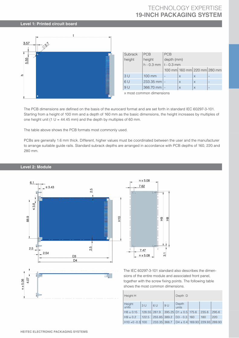
Level 1: Printed circuit board
Subrack
height
PCB
height
h - 0.3 mm
PCB
depth (mm)
t - 0.3 mm
100 mm 160 mm 220 mm 280 mm
3 U 100 mm - x x -
6 U 233.35 mm - x x -
9 U 366.70 mm - x x -
x most common dimensions
The PCB dimensions are defined on the basis of the eurocard format and are set forth in standard IEC 60297-3-101.
Starting from a height of 100 mm and a depth of 160 mm as the basic dimensions, the height increases by multiples of
one height unit (1 U = 44.45 mm) and the depth by multiples of 60 mm.
The table above shows the PCB formats most commonly used.
PCBs are generally 1.6 mm thick. Different, higher values must be coordinated between the user and the manufacturer
to arrange suitable guide rails. Standard subrack depths are arranged in accordance with PCB depths of 160, 220 and
280 mm.
Level 2: Module
The IEC 60297-3-101 standard also describes the dimen-
sions of the entire module and associated front panel,
together with the screw fixing points. The following table
shows the most common dimensions.
Height H Depth D
Height units
3 U 6 U 9 UDepth
units
H8 ± 0.15 128.55 261.9 395.25 D1 ± 0.5 175.6 235.6 295.6
H9 ± 0.2 122.5 255.85 389.2 D3 – 0.3 160 180 220
H10 +0 -0.3 100 233.35 366.7 D4 ± 0.4 169.93 229.93 289.93

WE CREATE YOUR ELECTRONIC WORLD
TECHNOLOGY EXPERTISE19-INCH PACKAGING SYSTEM
Level 3: Subrack
DIN EN 60297-3-101 provides a figure of 482.6 mm (19 inches) for the width of the subrack front.
The maximum subrack height is given as a multiple of one height unit (1 U), or 44.45 mm. This ensures that the subrack
height is coordinated with the height of the plug-in units used. Typical sizes are 3 U, 6 U and 9 U (refer to table).
The installation space for the modules is divided into horizontal pitch units (HP) of 5.08 mm (0.2 inch), or 84 HP for a
subrack width of 19 inches.
Height units 3 U 6 U 9 U
H1 ± 0.4 132.55 265.90 399.25
H5 ≥ 112.00 245.35 378.70
H6 ± 0.2 122.50 255.85 389.20
H7 + 0.5 -0 100.20 233.55 366.90
HE = U
TE = HP
HEITEC ELECTRONIC PACKAGING SYSTEMS
TECHNOLOGY EXPERTISE19-INCH PACKAGING SYSTEM
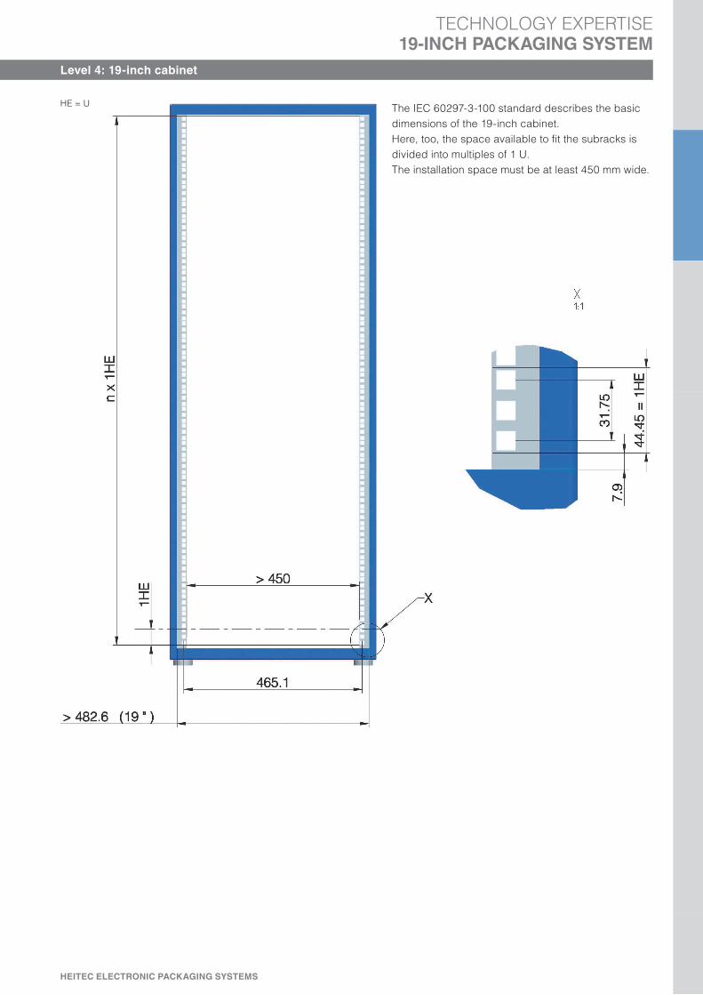
Level 4: 19-inch cabinet
The IEC 60297-3-100 standard describes the basic
dimensions of the 19-inch cabinet.
Here, too, the space available to fit the subracks is
divided into multiples of 1 U.
The installation space must be at least 450 mm wide.
HE = U

WE CREATE YOUR ELECTRONIC WORLD
TECHNOLOGY EXPERTISE19-INCH PACKAGING SYSTEM
Backplane
Backplane with plug connector as per
DIN 41612/IEC 60603-2 and IEC 61076-4-113
Typical application: VME/VME64 systems
Backplane with plug connector as per
IEC 61076-4-101
Typical application: CPCI systems
The IEC 60297-3-104 standard describes the dimensions of the
backplanes for the most common height variations (refer to table).Height units 3 U 6 U 9 U
H6 ± 0.2 122.50 255.85 389.20
H8 ± 0.15 128.55 261.90 395.25
HEITEC ELECTRONIC PACKAGING SYSTEMS
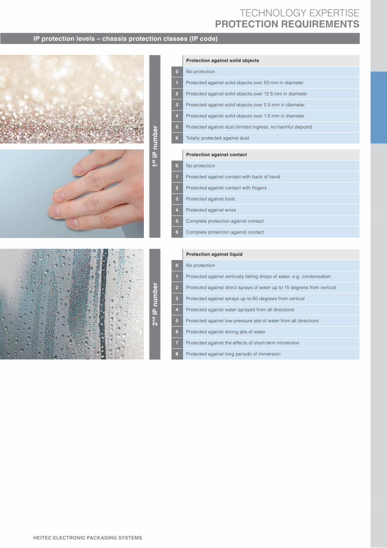
IP protection levels – chassis protection classes (IP code)
TECHNOLOGY EXPERTISEPROTECTION REQUIREMENTS
Protection against solid objects
0 No protection
1 Protected against solid objects over 50 mm in diameter
2 Protected against solid objects over 12.5 mm in diameter
3 Protected against solid objects over 2.5 mm in diameter
4 Protected against solid objects over 1.0 mm in diameter
5 Protected against dust (limited ingress, no harmful deposit)
6 Totally protected against dust
Protection against contact
0 No protection
1 Protected against contact with back of hand
2 Protected against contact with fingers
3 Protected against tools
4 Protected against wires
5 Complete protection against contact
6 Complete protection against contact
Protection against liquid
0 No protection
1 Protected against vertically falling drops of water, e.g. condensation
2 Protected against direct sprays of water up to 15 degrees from vertical
3 Protected against sprays up to 60 degrees from vertical
4 Protected against water sprayed from all directions
5 Protected against low-pressure jets of water from all directions
6 Protected against strong jets of water
7 Protected against the effects of short-term immersion
8 Protected against long periods of immersion
1s
t IP
nu
mb
er
2n
d I
P n
um
be
r

WE CREATE YOUR ELECTRONIC WORLD
Electromagnetic compatibility (EMC)
TECHNOLOGY EXPERTISEPROTECTION REQUIREMENTS
1
1
4
2
34
3
1
2
3
EMC gaskets, vertical
EMC gaskets, horizontal
EMC gaskets for cover plates
Mounting blocks4
The above diagram shows the extent to which EMC shielding influences the attenuation of the electromagnetic field. The attenua-
tion of a standard chassis with no suitable EMC components is thus much lower than that of a HeiPac Vario EMC subrack.
Of particular interest is the shielding factor provided by the attenuation.
HF attenuation (dB) Shielding (%)
6 50
20 90
40 99
60 99.9
Testing of measurements of the shielding effectiveness of empty chassis is based on DIN EN 61587-3 or military standards, e.g. MIL
STD 285 (US) or VG 95373 Part 15 (GER).
International EMC standards are published mainly by IEC (International Electrotechnical Commission) and CISPR (International Spe-
cial Committee on Radio Interference).
Key series of EMC standards with global importance: IEC 61000
MHz = frequency
dB = HF attenuation
1 E-Field = electric field (V/m)
EMC chassis
2 E-Field standard chassis
3 H-Field = magnetic field (A/m)
EMC chassis
4 H-Field standard chassis
1
23
4
EMC (electromagnetic compatibility) refers to the ability of an electrical device to function
satisfactorily in its electromagnetic environment without influencing this environment more
than is admissible. These requirements were taken into account when developing the
HEITEC subracks.
They are made entirely from metal and coated with a conductive surface finish.
Stainless steel EMC gaskets ensure a conductive connection between the separate parts.

HEITEC ELECTRONIC PACKAGING SYSTEMS
Nuts
TECHNOLOGY EXPERTISEMOUNTING ACCESSORIES
Screws
Screws are used to achieve a tight connection between
two or more components. They form part of a screw gear
consisting of two standardised, paired components.
Friction on the wedge-shaped thread under load prevents the
screws from coming loose.
Nuts are the counterpart to the screws. They have a standar-
dised inside thread that matches the thread of the screw.
The prismatic outside contour is shaped to accommodate a
wrench, which is used to tighten the nut. In terms of dimensi-
ons, the height of a nut is approximately half the width across
the flats.
Examples
Examples
Hexagonal head screw ISO 4017 - M12 x 100 - A4 - 50 - H
Screw plug DIN 910 - M24 x 2.5 - St
Panhead screw ISO 4762 - M10 x 65 - 9.8
Designation Reference standard,
e.g. ISO, DIN, EN
Dimensions and other
ratings, e.g.
M Metric thread
24 Nominal diameter d
100 Shank length l
Strength class, e.g.
9.8, 12.9, A2 - 50
Material, e.g.
St steel
Hexagonal nut ISO 4032 - M10 - St
Castellated nut DIN 935 - M4 x 1 - St
Hexagonal nut EN 1661 - M12 - 8
Designation Reference standard,
e.g. ISO, DIN, EN
Dimensions and other
ratings, e.g.
M Metric thread
10 Nominal diameter d
1 Thread pitch for
fine threads
Strength class, e.g
8, 12
Material, e.g.
St steel
Drive, e.g.
H Phillips
Z Pozidriv
T Torx


