
Scorpion Technology
Program Overview
DARPAPOC: Dr. Steve Walker
GTRIPOC: Dr. Jim McMichael
ARLPOC: Dr. Peter [email protected]: Mr. David Lyon
NDIA Fire Power Symposium
Parsipanny, NJ, 12 June 2007
J. McMichael, A. Glezer and A. Lovas, GTRIP. Plostins, G. Brown and J. Sahu, USARL
“Micro Adaptive Flow Control Applied to a Spinning Projectile”
SCORPIONSelf-Correcting Projectile
for Infantry Operation
in collaboration with:Mike Heiges, Kevin Massey, GTRI
Dave Lyon, Dave Hepner, Tom Harkin, USARLMark Allen, Brian English, Chris Rinehart, Georgia Tech
`
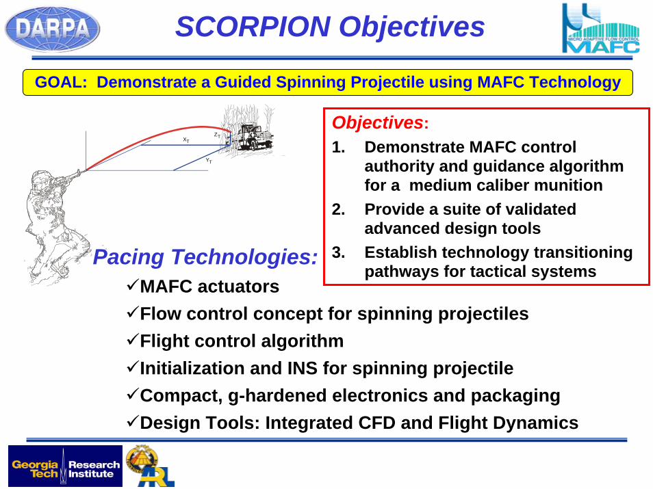
Pacing Technologies:MAFC actuatorsFlow control concept for spinning projectilesFlight control algorithm Initialization and INS for spinning projectileCompact, g-hardened electronics and packagingDesign Tools: Integrated CFD and Flight Dynamics
Objectives:1. Demonstrate MAFC control
authority and guidance algorithm for a medium caliber munition
2. Provide a suite of validated advanced design tools
3. Establish technology transitioning pathways for tactical systems
SCORPION Objectives
GOAL: Demonstrate a Guided Spinning Projectile using MAFC Technology
Z
Y
X T
T
T
-6-5-4-3-2-10123456
-10 -9 -8 -7 -6 -5 -4 -3 -2 -1 0 1 2 3 4 5 6 7 8 9 10
Psi
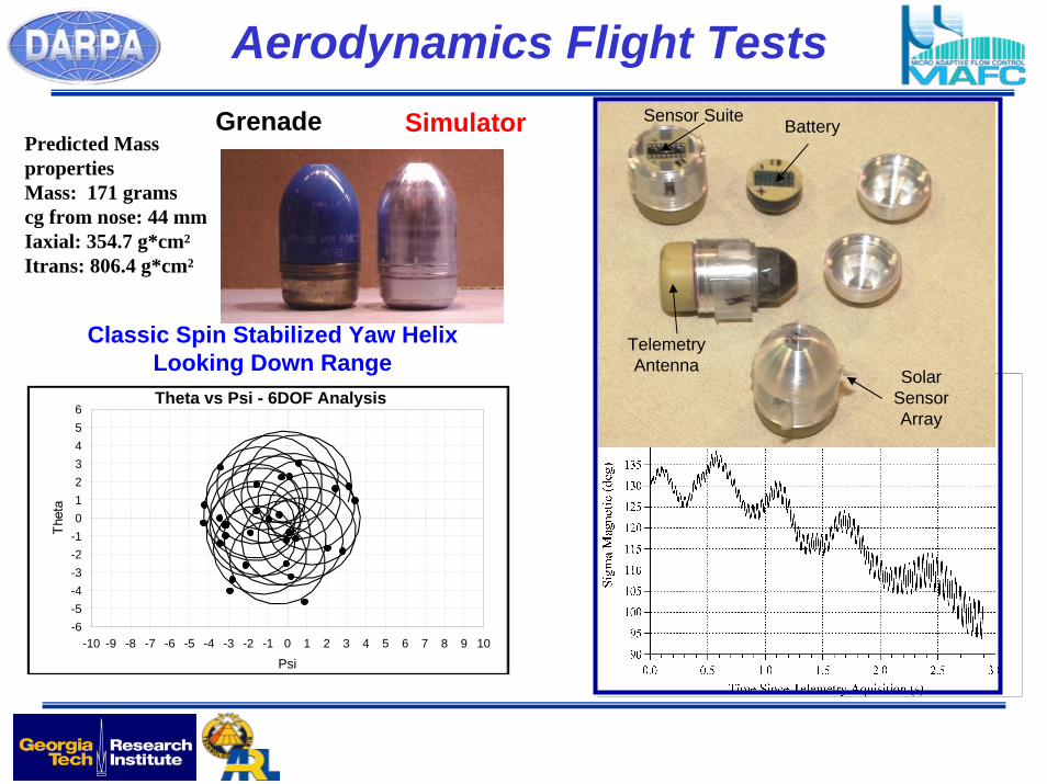
Theta vs Psi - 6DOF Analysis
Classic Spin Stabilized Yaw Helix Looking Down Range
Predicted Mass propertiesMass: 171 gramscg from nose: 44 mmIaxial: 354.7 g*cm²Itrans: 806.4 g*cm²
SimulatorGrenade
Aerodynamics Flight TestsBatterySensor Suite
TelemetryAntenna Solar
Sensor Array
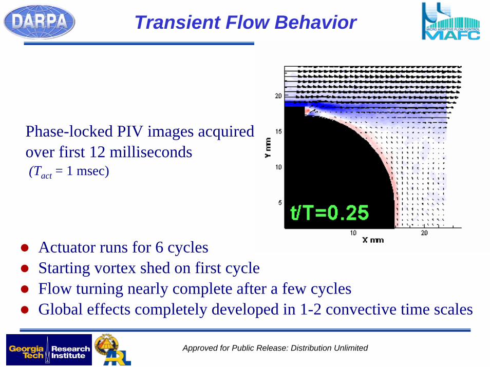
Transient Flow Behavior
Actuator runs for 6 cyclesStarting vortex shed on first cycleFlow turning nearly complete after a few cycles
Phase-locked PIV images acquiredover first 12 milliseconds(Tact = 1 msec)
Global effects completely developed in 1-2 convective time scales
Approved for Public Release: Distribution Unlimited
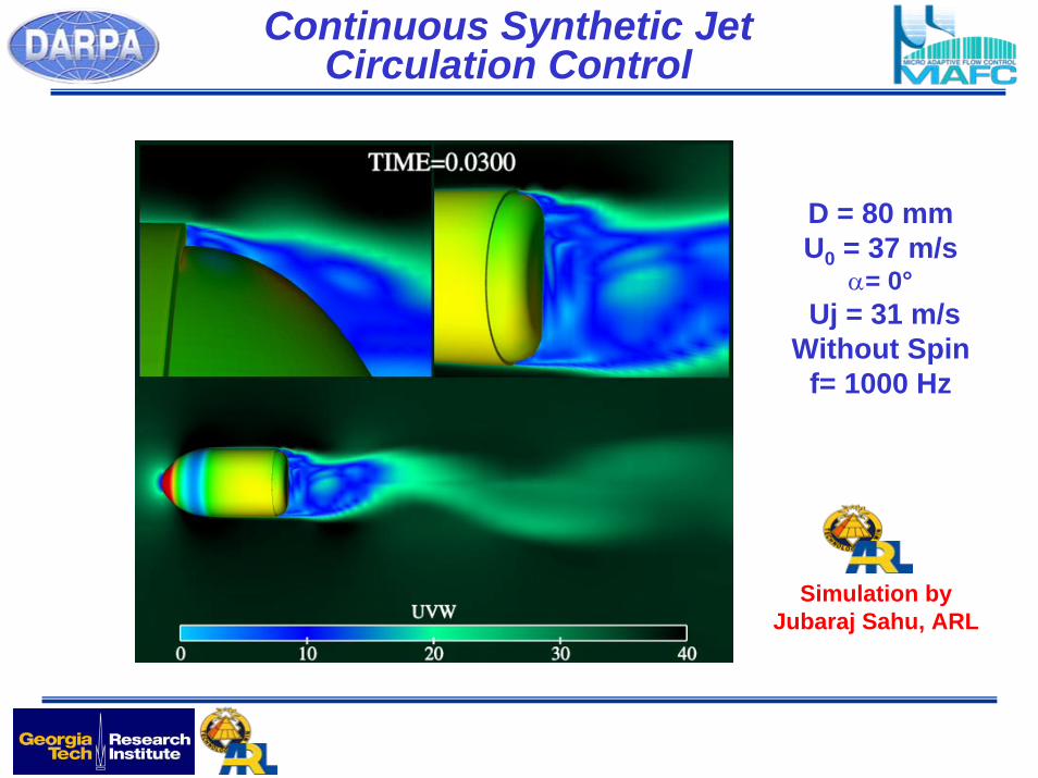
D = 80 mmU0 = 37 m/s
α= 0°Uj = 31 m/s
Without Spinf= 1000 Hz
Simulation byJubaraj Sahu, ARL
Continuous Synthetic Jet Circulation Control
-4.00
-3.00
-2.00
-1.00
0.00
1.00
2.00
3.00
40.0 45.0 50.0 55.0 60.0
Range, m
Forc
e, F
y
Fy - Jetoff
Fy - Jeton
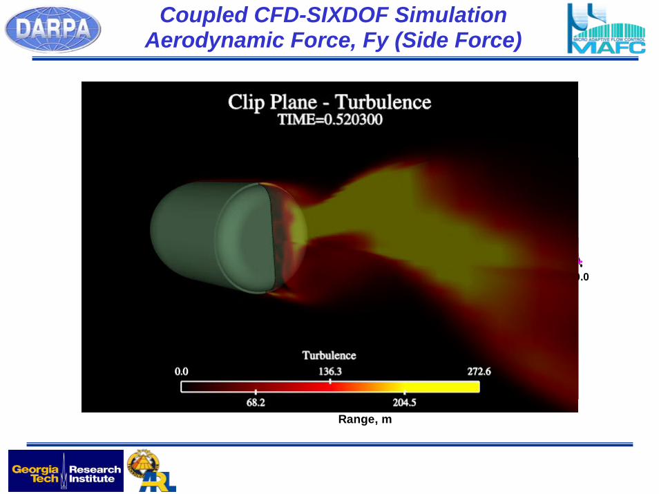
Coupled CFD-SIXDOF Simulation Aerodynamic Force, Fy (Side Force)
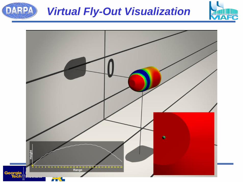
Virtual Fly-Out Visualization
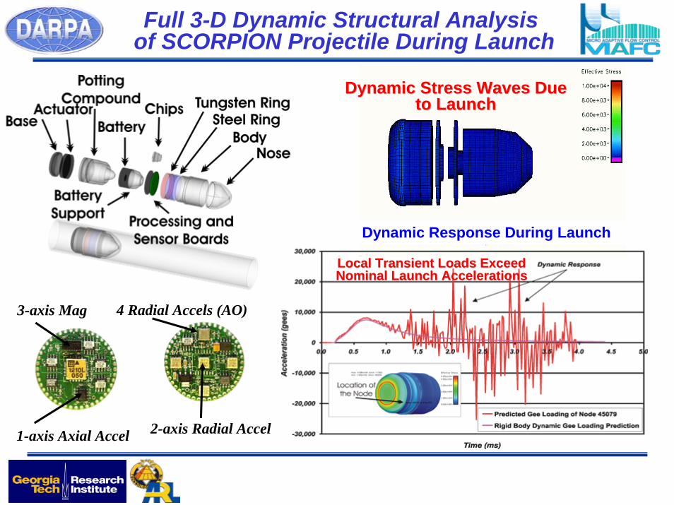
Dynamic Stress Waves Due Dynamic Stress Waves Due to Launchto Launch
Local Transient Loads Exceed Local Transient Loads Exceed Nominal Launch AccelerationsNominal Launch Accelerations
4 Radial Accels (AO)
1-axis Axial Accel 2-axis Radial Accel
3-axis Mag
Full 3-D Dynamic Structural Analysis of SCORPION Projectile During Launch
Dynamic Response During Launch
strake-like fences
Cartridge CaseObturator
BoattailBody
Ogive
Scorpion AssemblyOpen Loop Test
After ShockBefore Shock
• Developed High-G packaging to survive launch acceleration. GTRI-supplied electronic boards.
• Unit functioned appropriately after shockSimulating Magnetic Field
Spin simulated to initiate maneuver
High-G Shock (8,000 G’s)
Hot Wire Flow Measurements
AssembledJet
Velocity34 m/s
Control Electronics Calibration and High-G Ground Experiments
Scorpion Open Loop Controller Flow M easurement
0102030405060
0 0.005 0.01 0.015 0.02Time (sec)
Flow
Vel
ocity
(m/s
)
Open Loop Electronics Assembly
Processor Board
Boost Converter
Driver Board
Battery
Interface Connector
Open Loop Electronics and Control System Assembly
Open Loop Electronics and Control System Assembly
FlightHardware
Divert Flight Test Firing Protocol
After launch, wait 0.5 seconds, then activate at maximum voltage at same roll angle each revolution.Activate for 1/4 revolution (about 4 diaphragm cycles) such that force generated will be horizontal (left or right, as selected)On approximately 4 ms, and off 12 ms each revolution
On
Off
BoostConverter/Actuator
Driver Board
DC-DC
ActuatorH-Bridge
IMU Sensors
2 Rate
3 axis Mag
3 axis Accel
Radial Accels
Processor Board
Processor
G-Switch 3.3 V Oscillator
Battery
Divert Flight Test Firing Protocol
Actuator Timing
0.0
0.5
1.0
1.5
2.0
2.5
3.0
0 0.005 0.01 0.015 0.02 0.025 0.03 0.035 0.04
Time (sec)
Am
plitu
de Mag JMag KTrigger IndexDriver
Phase
Duration
Period
L2L1
M3M2M1 M4 M5
Data after Removing
Earth’s Field
Initialization of the Flight Control System
SCORPION ONBOARD SENSORS
Onboard Sensors include:
Axial and 2-axis Radial Accelerometer (3Components of Translational Accelerations)
3-axis Magnetometer (Along Projectile Principal Axes – Same as Accelerometers)
Pitch and Yaw Rate Sensors
2 Centripetal Acceleration Sensors (Roll Rate)
The inertial sensors respond to the projectile dynamics of launch and flight and provide measurements needed for projectile guidance. The sequence of events in a typical maneuvering Scorpion flight are readily apparent in the sensor data.
4 Radial Accels (AO)
1-axis Axial Accel 2-axis Radial Accel
3-axis Mag
DispersionControl
Holes in the Target!!!
Scorpion Test ResultsWith Closed LoopMuzzle Velocity
Control
Flight Configuration
Experimentally Demonstrated Novel Aerodynamic Control Methodology Capable
of Diverting Medium Caliber Munitions
Micro Adaptive Flow Control Actuation
Scorpion Technology ProgramAccomplishments
Demonstrated Micro-Adaptive Flow Control for divert of subsonic guided 40 mm grenade
Demonstrated Multi-disciplinary physics modeling – flew munition through the computer using High Performance Computing
First divert ever of a spin stabilized munition system at 60 hertz spin rateDeveloped a miniature, G hard, on board flight control systemDemonstrated initialization at muzzle exit – Velocity - OrientationDemonstrated open loop divert Demonstrated closed loop guidance to the target on major error source - VelocityCut on target dispersion due to muzzle velocity variation to one third of the system
value
25mm Scorpion
25mm Scorpion Projectile
Control Mechanism
Module
Inertial Sensor and Control
Module
Integrated Inertial Sensor and Control Electronics
17mm IMU (ARL) tightly integrated with processor (GTRI), power management (ARL/GTRI), interface hardware (GTRI), and control mechanism module (ARL)
IMU and
ProcessorInterface Electronics
Removable Micro-Squib
Control Mechanism Module
Tightly Integrated IMU and
Processor
25 mm Divert Video
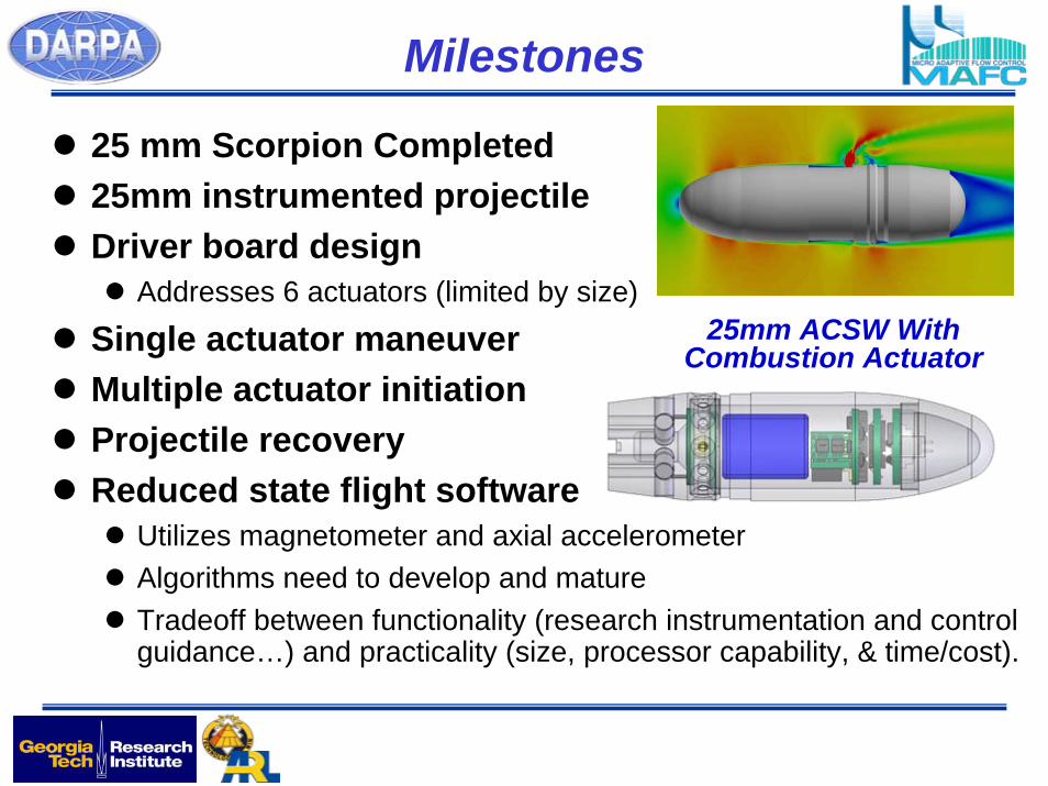
Milestones
25 mm Scorpion Completed25mm instrumented projectileDriver board design
Addresses 6 actuators (limited by size)
Single actuator maneuver Multiple actuator initiationProjectile recoveryReduced state flight software
Utilizes magnetometer and axial accelerometerAlgorithms need to develop and matureTradeoff between functionality (research instrumentation and control guidance…) and practicality (size, processor capability, & time/cost).
25mm ACSW With Combustion Actuator
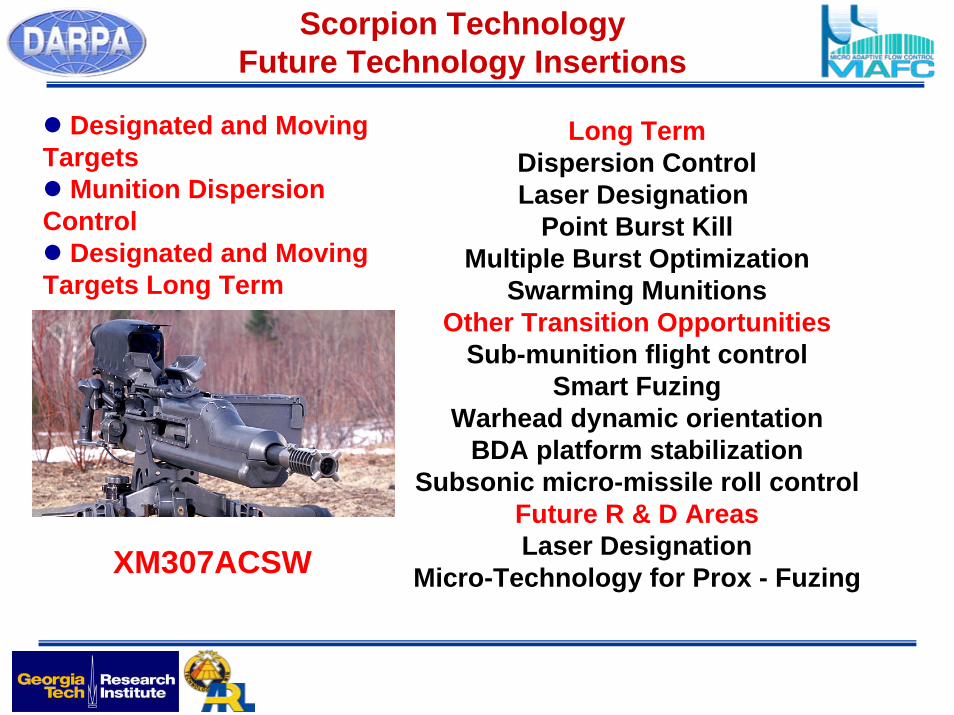
Scorpion TechnologyFuture Technology Insertions
Long TermDispersion ControlLaser Designation
Point Burst KillMultiple Burst Optimization
Swarming MunitionsOther Transition Opportunities
Sub-munition flight controlSmart Fuzing
Warhead dynamic orientationBDA platform stabilization
Subsonic micro-missile roll controlFuture R & D AreasLaser Designation
Micro-Technology for Prox - Fuzing
Designated and Moving Targets
Munition Dispersion Control
Designated and Moving Targets Long Term
XM307ACSW


