
PRODUCT CATALOGUE 2019
TEK4EDU Italy – Technology for Education Rev.1
TE
K4E
DU
Via
Don
Ce
sare
Pe
llizz
ari 1
30
- 3
002
0 M
eolo
(V
E)
- I
TALY
ww
w.T
EK
4E
DU
.co
min
fo@
tek
4ed
u.c
om
+3
9-(0
)421
.61
8.7
20
TEK4EDU Italy – Technology for Education
TEK4EDU (Technology for Education) is an Italian company based in Meolo (VE) which deals exclusively with educational products and equipment for experimentation, to be used in the laboratories of schools of all levels and universities.
DESIGN - PRODUCTION - MARKETING - TRAINING
Our products are designed to be used by Students and Teachers.This is why we design our products using the best possible quality so that they are Safe, Reliable,
Environmentally Friendly and Ergonomic.
Our products are accompanied by Manuals, which describe exercises and experiments written in English.
INDEXINTRODUCTION 4
PROCESS SIMULATORS and ARDUINO 6hydroSIM mod.T4E-SIM-01 greenhouseSIM mod.T4E-SIM-02 solarSIM mod.T4E-SIM-03 wirelessSIM mod.T4E-SIM-04 hydroSIM-Easy mod.T4E-SIM-01-E GreenhouseSIM-Easy mod.T4E-SIM-02-EsolarSIM-Easy mod.T4E-SIM-03-EwirelessSIM-Easy mod.T4E-SIM-04-E
BASIC ELECTRICITY AND ACCESSORIES FOR LABORATORY 10Basic Electricity Board mod.T4E-BCB-01Power Supply & Func.Generator mod.T4E-BOX-04Power amplifier mod.T4E-BOX-03myLAB mod.T4E-LAB-01Multimeter mod.T4E-INS-01Adjustable power supply mod.T4E-INS-02Function generator mod.T4E-INS-03Sound level meter mod.T4E-INS-04Lux level meter mod.T4E-INS-05
EDUCATIONAL ELECTRONICS MODULES AND ARDUINO 16Multifunction Power Supply mod.T4E-MOD-01DDS Function Generator mod.T4E-MOD-10Prototype Kit 1 mod.T4E-ACC-01
ARDUINO SHIELD BOARD 18BT & DDS Function Generator mod.T4E-ASB-01 EDU shield mod.T4E-ASB-02
PHISICS 20 Timer mod.T4E-BOX-01Timer Buetooth ver. mod.T4E-BOX-01-BTPhotogate mod.T4E-TAC-01 "g" measurement kit mod.T4E-TAC-03
MEDICAL DEVICES 23 Drop Buzzer mod.T4E-BOX-02
ACCESSORIES 24 HDMI Receiver mod.T4E-ACC-08
TEK4EDU Italy – Technology for Education
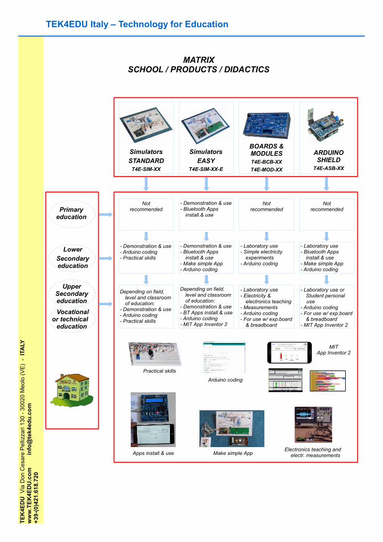
MATRIXSCHOOL / PRODUCTS / DIDACTICS
Primary education
Lower
Secondary education
Simulators
STANDARDT4E-SIM-XX
Simulators
EASYT4E-SIM-XX-E
BOARDS & MODULEST4E-BCB-XX
T4E-MOD-XX
ARDUINO SHIELD
T4E-ASB-XX
Not recommended
- Demonstration & use- Bluetooth Apps
install.& use
Depending on field, level and classroom of education:
- Demonstration & use- Arduino coding- Practical skills
- Demonstration & use- Bluetooth Apps
install.& use- Make simple App- Arduino coding
- Demonstration & use- Arduino coding- Practical skills
Depending on field, level and classroom of education:
- Demonstration & use- BT Apps install.& use- Arduino coding- MIT App Inventor 2
Not recommended
Not recommended
- Laboratory use- Simple electricity
experiments- Arduino coding
- Laboratory use- Bluetooth Apps
install.& use- Make simple App- Arduino coding
- Laboratory use- Electricity &
electronics teaching- Measurements - Arduino coding- For use w/ exp.board
& breadboard
- Laboratory use or Student personal
use- Arduino coding- For use w/ exp.board
& breadboard- MIT App Inventor 2
MIT App Inventor 2
Arduino coding
Practical skills
Make simple AppApps install.& useElectronics teaching and
electr. measurements
Upper Secondary education
Vocational or technical
education
TE
K4E
DU
Via
Don
Ce
sare
Pe
llizz
ari 1
30
- 3
002
0 M
eolo
(V
E)
- I
TALY
ww
w.T
EK
4E
DU
.co
min
fo@
tek
4ed
u.c
om
+3
9-(0
)421
.61
8.7
20

INTRODUCTION
This document contains an extract of the information available for each product.For more details, please consult the website www.tek4edu.com where you can download the brochure for each
product and view the video tutorials showing the operation of the products.
We have developed a series of products that we propose for the setting of educational laboratories, for experiments in electricity, electronics and coding.They are flexible. They can be used and adapted to the needs and skills required by the educational institution:
from simple demonstrative use to the in-depth analysis of specific programming topics.They are functional. The hardware and software have already been designed so that they can be used quickly
and without the need for specific professors' skills.
The design philosophy is open-source, so all the software or codes used are provided, so that the Student has a complete and functional project model to study and eventually modify.
The products have been developed as proposals:
- to support school staff in identifying an experimental technological path compatible with the guidelines of the Ministry of Education and
- for schools or institutes of the highest grade who wish to give their students the opportunity to carry out active experimentation applied to new technologies.
DocFile:T4E_CAT_2019_R.1_EN 4/24
TE
K4E
DU
di
GIA
NL
UIG
I LA
GA
NA
RA
Via
Don
Ce
sare
Pe
llizz
ari,1
30
- 30
020
Me
olo
(VE
) –
ITA
LYP.
IVA
: IT
0435
435
0276
– N
.RE
A:
VE
-40
4611
- N
.AE
E:
IT16
0800
000
094
56w
ww
.tek
4ed
u.co
m
info
@te
k4ed
u.c
om
+
39-0
421-
618-
720
TEK4EDU Italy – Technology for Education intro 1/2
Primary school solutions:
"Easy" simulators are geared towards demonstrating and using hardware and software technology.
They deal in a simple and intuitive way with current topics such as the operation of a hydroelectric power station or a domestic solar plant or a greenhouse for protected cultivation or a wireless transmission system, using an attractive color design relating to the subject in question.
The child must not have specific knowledge: he must perform new but simple and stimulating manual operations (for example, turn a small potentiometer in order to simulate changing the water level in the water basin) and check its effects.
He will have more INPUTs to modify in order to obtain a particular and defined OUTPUT: by playing and confronting himself with his companions, he will learn that to get a certain goal he must be in a certain combination of conditions.
Example Simulator "Easy"
We believe that this "logical" approach to achieving a goal is helpful for the development of a child's computational thinking.
In addition, each child will be able to carry out operations with the tablet supplied to the School: read a QRcode, install and use the App relevant to the topic, contributing to the demolition of the digital divide present among companions of different economic or social conditions.
The teacher must not have specific electronic or computer skills: the simulator is ready to use because every electronic card present is already mounted or configured.
Solutions for lower secondary school:
1) The "Easy" simulators, just described, are a valid solution to address the topics of the TECHNOLOGY course: they offer food for thought, discussion and in-depth analysis of the topics covered during frontal lessons. In addition to what has already been described, they allow you to enter the world of coding using the popular Arduino board, which will allow the Teacher to:
- show the written code that defines and regulates the operation of the simulator- perform even simple changes to the code to show different or even incorrect operation
The kids will learn how to use simple free applications, which will allow them to create simple and personalized Android Apps that will communicate between the simulator and the Android device.

DocFile:T4E_CAT_2019_R.1_EN 5/24
TE
K4E
DU
di
GIA
NL
UIG
I LA
GA
NA
RA
Via
Don
Ce
sare
Pe
llizz
ari,1
30
- 30
020
Me
olo
(VE
) –
ITA
LYP.
IVA
: IT
0435
435
0276
– N
.RE
A:
VE
-40
4611
- N
.AE
E:
IT16
0800
000
094
56w
ww
.tek
4ed
u.co
m
info
@te
k4ed
u.c
om
+
39-0
421-
618-
720
TEK4EDU Italy – Technology for Education intro 2/2
Example"Standard" Simulator
2) The "Standard" Simulators are a valid solution to address the topics of the TECHNOLOGY teaching with a greater practical / manual approach.
The kids will not be mere passive users of the technology around them: they will have to interact actively with the technology (Tinkering zone). In fact they will have to:
- build and experiment- learn to recognize materials, mechanical, electrical and
electronic components- understand the main function of the individual component
and that which characterizes it in the context of a complex system to which it belongs
All the necessary components are supplied in order to be able to assemble a simple electrical circuit without the need to perform risky operations.
The kid will be able to directly touch and know the components that make up the simulator.
Moreover, using the diagrams, drawings and images provided, he will learn to assemble his simulator.
3) Edu Shield is an educational board for Arduino that allows you to perform 12 coding experiments.It fits on the Arduino board and contains all the necessary
electrical components: no wiring must be performed, eliminating the risk of errors and eliminating the time required to prepare the circuits.
For each experiment the appropriate code is provided, functioning and commented.
For some experiments using Android devices, the App is provided, which the boy will learn to install and use.
4) educational modules Power supply and Function generator are flexible products that can be part of the TECHNOLOGY laboratory: they are complete with all the accessories that allow them to be used with experimental circuits created in the laboratory.
5) myLAB is a complete solution for setting up the TECHNOLOGY laboratory that allows you to perform simple electrical and electronic experiments by building circuits and prototypes, as well as coding executions.
6) the Basic Electricity Board is a board that allows simple electricity experiments.
Solutions for upper secondary school:1) Both the "Easy" and "Standard" Simulators can be used to
perform coding exercises in all those schools that want to use the Arduino platform, compatible with the address of the institution. The boys using:- the Standard version, they can modify the code or add
components to develop their creativity,
- vice versa with, the Easy version, they will be able to become familiar with the programming of Android Apps using the free development environment MIT App Inventor 2 for open-source Android applications managed by MIT (Massachusetts Institute of Technology). They will be able to understand how the App was developed and modify it.
2) with the Edu Shield, in addition to executing the Arduino coding exercises, they will understand how the Android Apps were developed and how they can be modified and customized.
3) with the BT&DDS Function Generator shield will have a compact and portable generator of functions controlled via the App, ideal for performing electricity and electronic experiments and for learning to manage a DDS Generator module and the Bluetooth interface
4) with the educational modules Power supply and Function generator, they will be able to study their design and management with microprocessors, make Arduino coding exercises, and use them as laboratory instruments with experimental circuits.
5) with the Basic Electricity Board they can perform experiments and learn how to use laboratory instruments: sound level meter, lux meter, function generator, oscilloscope ...
6) our Power Amplifier is the essential accessory when you want to experiment the characteristics of lamps, speakers, motors ... and the power of the function generator is not enough.
Edu Shield for Arduino
Exampls educational module
Basic Electricity Board
TEK4EDU Italy – Technology for Education
Hydroelectric power stationhydroSIM mod.T4E-SIM-01
TE
K4E
DU
Via
Don
Ce
sare
Pe
llizz
ari 1
30
- 3
002
0 M
eolo
(V
E)
- I
TALY
ww
w.T
EK
4E
DU
.co
min
fo@
tek
4ed
u.c
om
(+3
9) 0
421
.61
8.7
20
DocFile:T4E_CAT_2019_R.1_EN 6/24
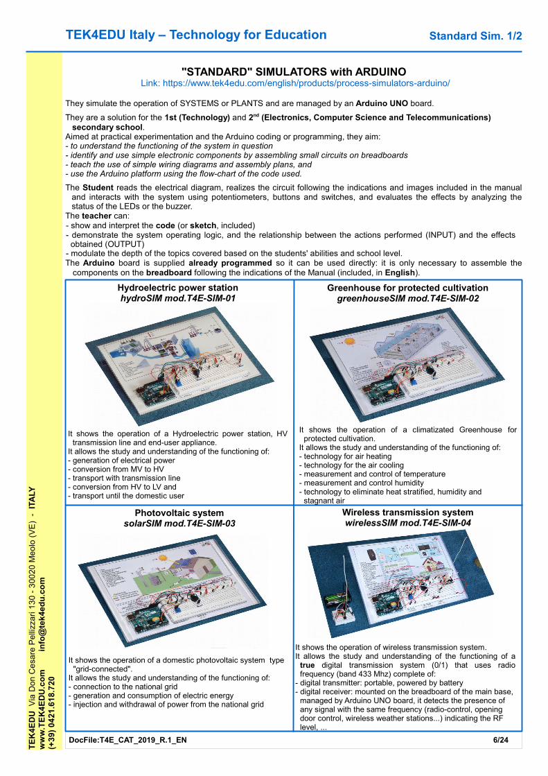
"STANDARD" SIMULATORS with ARDUINO Link: https://www.tek4edu.com/english/products/process-simulators-arduino/
They simulate the operation of SYSTEMS or PLANTS and are managed by an Arduino UNO board.
They are a solution for the 1st (Technology) and 2nd (Electronics, Computer Science and Telecommunications) secondary school.
Aimed at practical experimentation and the Arduino coding or programming, they aim:- to understand the functioning of the system in question- identify and use simple electronic components by assembling small circuits on breadboards- teach the use of simple wiring diagrams and assembly plans, and- use the Arduino platform using the flow-chart of the code used.
The Student reads the electrical diagram, realizes the circuit following the indications and images included in the manual and interacts with the system using potentiometers, buttons and switches, and evaluates the effects by analyzing the status of the LEDs or the buzzer.
The teacher can:- show and interpret the code (or sketch, included)- demonstrate the system operating logic, and the relationship between the actions performed (INPUT) and the effects
obtained (OUTPUT)- modulate the depth of the topics covered based on the students' abilities and school level.The Arduino board is supplied already programmed so it can be used directly: it is only necessary to assemble the
components on the breadboard following the indications of the Manual (included, in English).
Greenhouse for protected cultivationgreenhouseSIM mod.T4E-SIM-02
Photovoltaic systemsolarSIM mod.T4E-SIM-03
Wireless transmission systemwirelessSIM mod.T4E-SIM-04
Standard Sim. 1/2
It shows the operation of wireless transmission system.It allows the study and understanding of the functioning of a
true digital transmission system (0/1) that uses radio frequency (band 433 Mhz) complete of:
- digital transmitter: portable, powered by battery- digital receiver: mounted on the breadboard of the main base,
managed by Arduino UNO board, it detects the presence of any signal with the same frequency (radio-control, opening door control, wireless weather stations...) indicating the RF level, ...
It shows the operation of a Hydroelectric power station, HV transmission line and end-user appliance.
It allows the study and understanding of the functioning of:- generation of electrical power- conversion from MV to HV- transport with transmission line- conversion from HV to LV and - transport until the domestic user
It shows the operation of a climatizated Greenhouse for protected cultivation.
It allows the study and understanding of the functioning of: - technology for air heating- technology for the air cooling- measurement and control of temperature- measurement and control humidity- technology to eliminate heat stratified, humidity and
stagnant air
It shows the operation of a domestic photovoltaic system type "grid-connected".
It allows the study and understanding of the functioning of:- connection to the national grid- generation and consumption of electric energy- injection and withdrawal of power from the national grid
DocFile:T4E_CAT_2019_R.1_EN 7/24
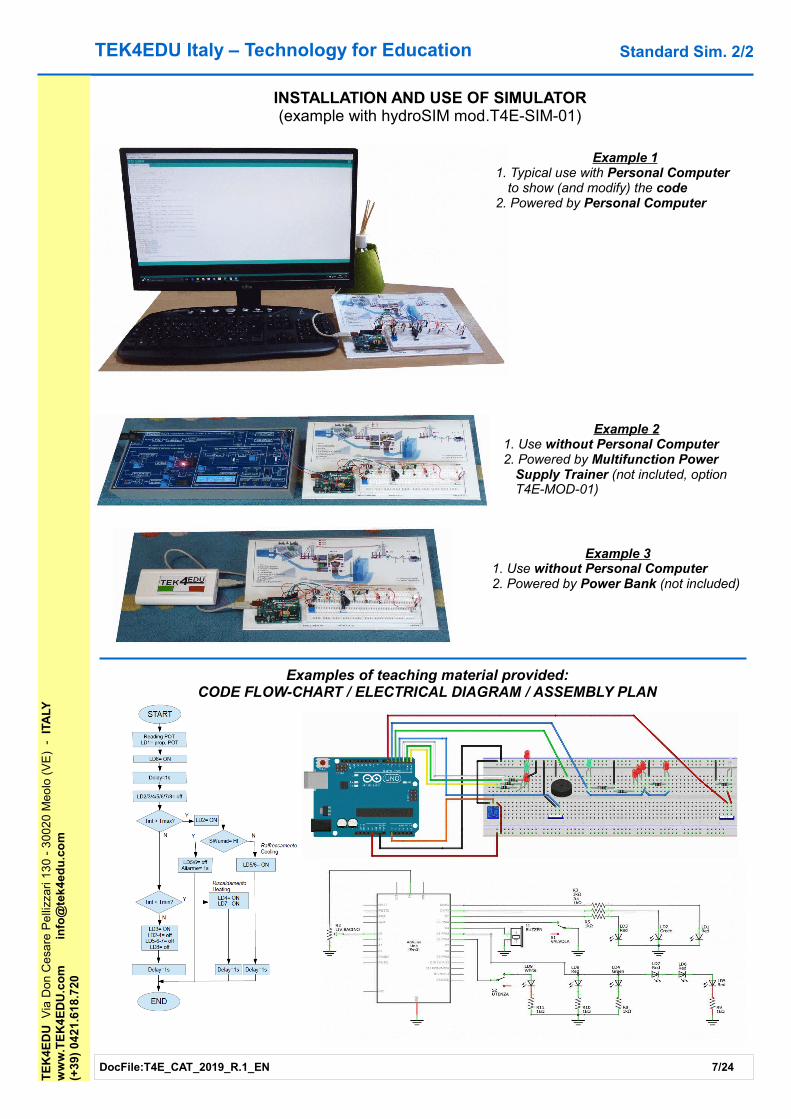
Example 21. Use without Personal Computer2. Powered by Multifunction Power
Supply Trainer (not incluted, option T4E-MOD-01)
INSTALLATION AND USE OF SIMULATOR(example with hydroSIM mod.T4E-SIM-01)
Example 31. Use without Personal Computer2. Powered by Power Bank (not included)
Example 11. Typical use with Personal Computer
to show (and modify) the code2. Powered by Personal Computer
TEK4EDU Italy – Technology for Education T
EK
4ED
U V
ia D
on C
esa
re P
elli
zzar
i 13
0 -
300
20
Meo
lo (
VE
) -
ITA
LYw
ww
.TE
K4
ED
U.c
om
info
@te
k4e
du
.co
m(+
39)
04
21.6
18.
720
Examples of teaching material provided:CODE FLOW-CHART / ELECTRICAL DIAGRAM / ASSEMBLY PLAN
Standard Sim. 2/2
TEK4EDU Italy – Technology for EducationT
EK
4ED
U V
ia D
on C
esa
re P
elli
zzar
i 13
0 -
300
20
Meo
lo (
VE
) -
ITA
LYw
ww
.TE
K4
ED
U.c
om
info
@te
k4e
du
.co
m(+
39)
04
21.6
18.
720
DocFile:T4E_CAT_2019_R.1_EN 8/24
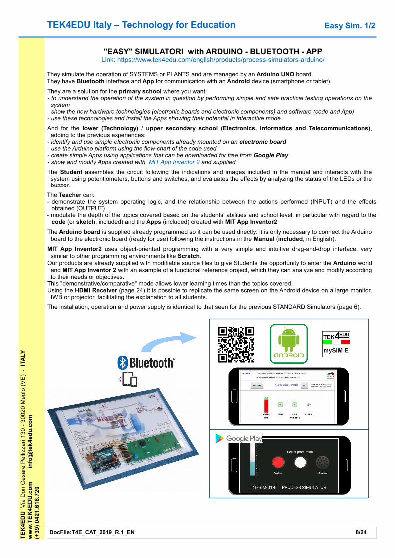
"EASY" SIMULATORI with ARDUINO - BLUETOOTH - APPLink: https://www.tek4edu.com/english/products/process-simulators-arduino/
They simulate the operation of SYSTEMS or PLANTS and are managed by an Arduino UNO board.They have Bluetooth interface and App for communication with an Android device (smartphone or tablet).
They are a solution for the primary school where you want:- to understand the operation of the system in question by performing simple and safe practical testing operations on the
system- show the new hardware technologies (electronic boards and electronic components) and software (code and App)- use these technologies and install the Apps showing their potential in interactive mode
And for the Iower (Technology) / upper secondary school (Electronics, Informatics and Telecommunications), adding to the previous experiences:
- identify and use simple electronic components already mounted on an electronic board- use the Arduino platform using the flow-chart of the code used- create simple Apps using applications that can be downloaded for free from Google Play- show and modify Apps created with MIT App Inventor 2 and supplied
The Student assembles the circuit following the indications and images included in the manual and interacts with the system using potentiometers, buttons and switches, and evaluates the effects by analyzing the status of the LEDs or the buzzer.
The Teacher can:- demonstrate the system operating logic, and the relationship between the actions performed (INPUT) and the effects
obtained (OUTPUT)- modulate the depth of the topics covered based on the students' abilities and school level, in particular with regard to the
code (or sketch, included) and the Apps (included) created with MIT App Inventor2
The Arduino board is supplied already programmed so it can be used directly: it is only necessary to connect the Arduino board to the electronic board (ready for use) following the instructions in the Manual (included, in English).
MIT App Inventor2 uses object-oriented programming with a very simple and intuitive drag-and-drop interface, very similar to other programming environments like Scratch.
Our products are already supplied with modifiable source files to give Students the opportunity to enter the Arduino world and MIT App Inventor 2 with an example of a functional reference project, which they can analyze and modify according to their needs or objectives.
This "demonstrative/comparative" mode allows lower learning times than the topics covered. Using the HDMI Receiver (page 24) it is possible to replicate the same screen on the Android device on a large monitor,
IWB or projector, facilitating the explanation to all students.
The installation, operation and power supply is identical to that seen for the previous STANDARD Simulators (page 6).
Easy Sim. 1/2

TEK4EDU Italy – Technology for EducationT
EK
4ED
U V
ia D
on C
esa
re P
elli
zzar
i 13
0 -
300
20
Meo
lo (
VE
) -
ITA
LYw
ww
.TE
K4
ED
U.c
om
info
@te
k4e
du
.co
m(+
39)
04
21.6
18.
720
DocFile:T4E_CAT_2019_R.1_EN 9/24
Easy Sim. 2/2
Design Blocks
Screenshot examples of MIT APP INVENTOR2(esempio con greenhouseSIM-Easy mod.T4E-SIM-02-E)
Hydroelectric power stationhydroSIM-Easy mod.T4E-SIM-01-E
Greenhouse for protected cultivationgreenhouseSIM-Easy mod.T4E-SIM-02-E
Photovoltaic systemsolarSIM-Easy mod.T4E-SIM-03-E
Wireless transmission systemwirelessSIM-Easy mod.T4E-SIM-04-E
It shows the operation of wireless transmission system.It allows the study and understanding of the functioning of a
true digital transmission system (0/1) that uses radio frequency (band 433 Mhz) complete of:
- digital transmitter: portable, powered by battery- digital receiver: mounted on the breadboard of the main base,
managed by Arduino UNO board, it detects the presence of any signal with the same frequency (radio-control, opening door control, wireless weather stations...) indicating the RF level, ...
It shows the operation of a Hydroelectric power station, HV transmission line and end-user appliance.
It allows the study and understanding of the functioning of:- generation of electrical power- conversion from MV to HV- transport with transmission line- conversion from HV to LV and - transport until the domestic user
It shows the operation of a climatizated Greenhouse for protected cultivation.
It allows the study and understanding of the functioning of: - technology for air heating- technology for the air cooling- measurement and control of temperature- measurement and control humidity- technology to eliminate heat stratified, humidity and
stagnant air
It shows the operation of a domestic photovoltaic system type "grid-connected".
It allows the study and understanding of the functioning of:- connection to the national grid- generation and consumption of electric energy- injection and withdrawal of power from the national grid

TEK4EDU Italy – Technology for Education
The Basic Electricity Board mod.T4E-BCB-01 has been designed to allow the experimentation of simple electrical circuits that will be realized using the included crocodile cables.
You can:- study the electrical and functional characteristics- understand its functional limits and- analyze the effects of their presence in the circuitsof all the electrical and mechanical components on the board.It can be used by students of any level of educational
institutions, to support frontal lessons.For those of the lower secondary school (science and
technology), it will be possible to perform simple electricity experiments and learn about the components using the power supply and the multimeter.
For those of upper secondary school, depending on whether high schools or technical institutes, it will be possible to perform further and more advanced experiments:
- in direct current using an adjustable power supply- in alternating current using a function generator- in alternating current to observe the variables that change
over time, learning to use an oscilloscope- of acoustic physics (sound): for measurements of the sound
intensity emitted by the included buzzer, learning to use a sound level meter
- of optical physics: experimentally verifying the effects that have the amplitude and the frequency of a signal that feeds a light bulb on the perception of the human eye, using a function generator and a power amplifier and learning to use a luxmeter
- to study the technical characteristics of components not included in the card: motors, loudspeakers, ..
The board allows the practical demonstration of the laws that regulate the phenomena analyzed:
- Laws of Ohm and Kirchhoff- Joule effect and calculation of the power dissipated by a
resistor- Series and parallel resistors and capacitors- Functional limits of the resistor, condenser and bulb- RL, RC and RLC circuits: capacitor charge, current passing
through an inductor, ...- DC circuits: use of variable (tensions) constant over time- AC circuits: use of variables that vary over time. The
waveform and the concept of period and frequency
(Cont.)To understand the phenomena that surround us it is important to know how to use the measuring instruments. By using this board the Students will learn how to use the instrumentation and execute measurements correctly:
- direct measures: e.g. voltage, current ...- indirect measures: e.g. carrying out the voltage and current measurements you can calculate the resistance R as V: I
They will learn to use:- the power supply: suggested the use of an adjustable DC power supply with a maximum voltage of + 12VDC
- the multimeter for voltage and current measurements, in direct current (DC) and alternating current (AC)
- the function generator: use of a sinusoidal waveform for experiments in alternating current and square wave for measurement of transients (e.g. charge of a capacitor)
- the oscilloscope: to observe signals that vary over time
The educational manual supplied with the board, provides all the information necessary to understand the characteristics of the components inside it and how to use the board to carry out the suggested experiments.
For each experiment it is described:- the circuit to be set up, any theoretical laws and / or mathematical formulas that regulate it
- the mode to perform the experiment and the operations not to be performed
- the suggested instrumentation and how it must be connected and set up
- the comment of the experimental results obtainedThe Teacher, based on the subject of teaching and the level of the class, will choose in the manual the experiments to be carried out to the Students, who are proposed with the level of knowledge required increasing.
The simplest are the cognitive type of the component under examination, in which only the multimeter is used, without even the need to use the power supply.
They follow:- experiments in which the circuit is powered and the multimeter is used to carry out direct current measurements (DC)
- experiments in which a function generator is used to analyze the behavior of the circuit when the waveform used varies and its frequency (AC)
- experiments in which a function generator and a power amplifier are used to analyze the visual behavior of the light bulbs
TE
K4E
DU
Via
Don
Ce
sare
Pe
llizz
ari 1
30
- 3
002
0 M
eolo
(V
E)
-
ITA
LYw
ww
.TE
K4
ED
U.c
om
info
@te
k4e
du
.co
m(+
39)
04
21.6
18.
720
DocFile:T4E_CAT_2019_R.1_EN 10/24
BASIC ELECTRICITY BOARDmod.T4E-BCB-01
Basic Circuits 1/6
TEK4EDU Italy – Technology for EducationT
EK
4ED
U V
ia D
on C
esa
re P
elli
zzar
i 13
0 -
300
20
Meo
lo (
VE
) -
IT
ALY
ww
w.T
EK
4E
DU
.co
min
fo@
tek
4ed
u.c
om
(+3
9) 0
421
.61
8.7
20
DocFile:T4E_CAT_2019_R.1_EN 11/24
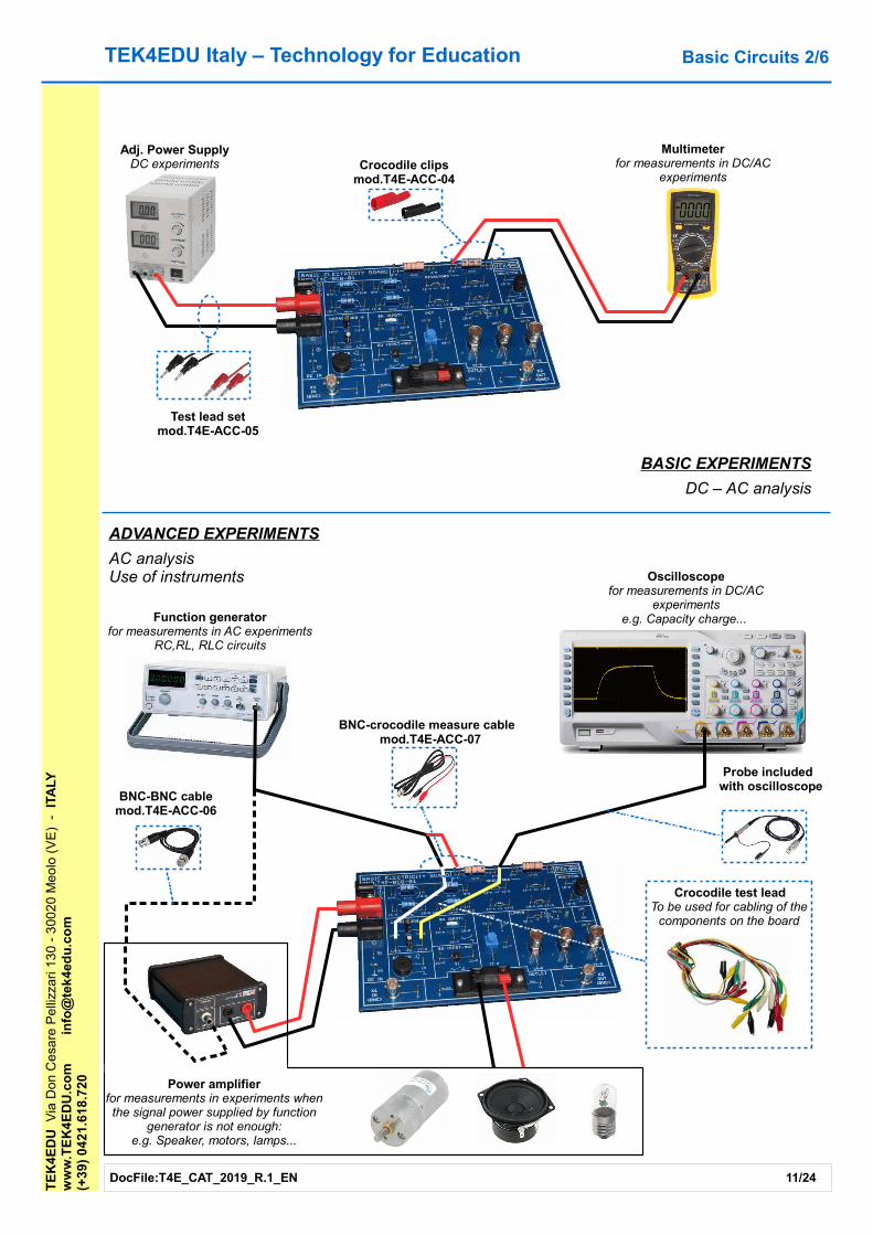
BASIC EXPERIMENTS
DC – AC analysis
Crocodile test leadTo be used for cabling of the
components on the board
Adj. Power SupplyDC experiments
Multimeterfor measurements in DC/AC
experiments
ADVANCED EXPERIMENTS
AC analysis Use of instruments Oscilloscope
for measurements in DC/AC experiments
e.g. Capacity charge... Function generatorfor measurements in AC experiments
RC,RL, RLC circuits
Power amplifierfor measurements in experiments when the signal power supplied by function
generator is not enough:e.g. Speaker, motors, lamps...
Test lead setmod.T4E-ACC-05
Crocodile clipsmod.T4E-ACC-04
BNC-crocodile measure cable mod.T4E-ACC-07
BNC-BNC cablemod.T4E-ACC-06
Probe included with oscilloscope
Basic Circuits 2/6
TEK4EDU Italy – Technology for Education
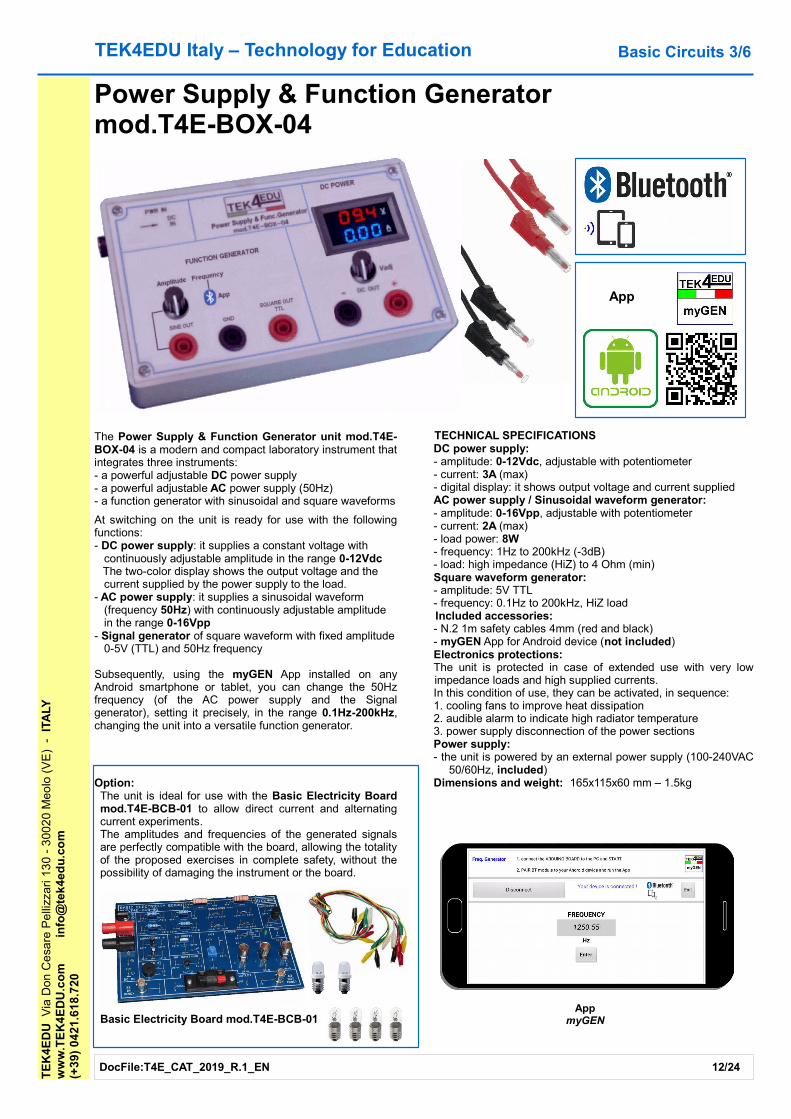
The Power Supply & Function Generator unit mod.T4E-BOX-04 is a modern and compact laboratory instrument that integrates three instruments:- a powerful adjustable DC power supply- a powerful adjustable AC power supply (50Hz)- a function generator with sinusoidal and square waveforms
At switching on the unit is ready for use with the following functions:- DC power supply: it supplies a constant voltage with
continuously adjustable amplitude in the range 0-12VdcThe two-color display shows the output voltage and the current supplied by the power supply to the load.
- AC power supply: it supplies a sinusoidal waveform (frequency 50Hz) with continuously adjustable amplitude in the range 0-16Vpp
- Signal generator of square waveform with fixed amplitude 0-5V (TTL) and 50Hz frequency
Subsequently, using the myGEN App installed on any Android smartphone or tablet, you can change the 50Hz frequency (of the AC power supply and the Signal generator), setting it precisely, in the range 0.1Hz-200kHz, changing the unit into a versatile function generator.
Option:The unit is ideal for use with the Basic Electricity Board mod.T4E-BCB-01 to allow direct current and alternating current experiments.The amplitudes and frequencies of the generated signals are perfectly compatible with the board, allowing the totality of the proposed exercises in complete safety, without the possibility of damaging the instrument or the board.
Basic Electricity Board mod.T4E-BCB-01
TECHNICAL SPECIFICATIONSDC power supply:- amplitude: 0-12Vdc, adjustable with potentiometer - current: 3A (max)- digital display: it shows output voltage and current supplied AC power supply / Sinusoidal waveform generator:- amplitude: 0-16Vpp, adjustable with potentiometer- current: 2A (max)- load power: 8W- frequency: 1Hz to 200kHz (-3dB)- load: high impedance (HiZ) to 4 Ohm (min)Square waveform generator:- amplitude: 5V TTL- frequency: 0.1Hz to 200kHz, HiZ loadIncluded accessories: - N.2 1m safety cables 4mm (red and black)- myGEN App for Android device (not included)Electronics protections:The unit is protected in case of extended use with very low impedance loads and high supplied currents.In this condition of use, they can be activated, in sequence:1. cooling fans to improve heat dissipation2. audible alarm to indicate high radiator temperature3. power supply disconnection of the power sectionsPower supply:- the unit is powered by an external power supply (100-240VAC
50/60Hz, included) Dimensions and weight: 165x115x60 mm – 1.5kg
AppmyGEN
Power Supply & Function Generatormod.T4E-BOX-04
TE
K4E
DU
Via
Don
Ce
sare
Pe
llizz
ari 1
30
- 3
002
0 M
eolo
(V
E)
-
ITA
LYw
ww
.TE
K4
ED
U.c
om
info
@te
k4e
du
.co
m(+
39)
04
21.6
18.
720
DocFile:T4E_CAT_2019_R.1_EN 12/24
App
Basic Circuits 3/6

TEK4EDU Italy – Technology for Education
The mAMP power amplifier unit mod.T4E-BOX-03 has been designed to be used in experiments where you want to use signals and waveforms that can not be provided by the typical signal or waveform generators present in the laboratories, due to their insufficient capacity to supply current or power.
Its main features are:- High impedance input compatible with signals provided by any signal generator or waveform- Output with very low impedance to drive any kind of resistive, inductive or capacitive load- High output current (> 2.5A)- Voltage gain (Output / Input) equal to 10 (20dB) to allow the use of signal generators or waveform with limited voltage range
provided- Accept any kind of signal or waveform with the presence of continuous or non-continuous component- AC / DC selector which allows to output a signal without a DC component (eg + 10V/-10V, AC mode) or with a DC
component (eg 0V-10V, DC mode). In particular, in DC mode, by supplying a constant voltage (DC, positive or negative), the unit behaves like a variable DC power supply and can supply a positive or negative voltage on the load.
- Protection circuits for incorrect supply voltage, for overcurrent, short circuit to ground and overtemperature- The amplitude of the input signal can saturate the output stage without problems for the unitThe unit can be used in experiments where you want to "test" the electrical characteristics of:- engines: rotation, absorbed current ...- passive speakers and loudspeakers: frequency response curve, sensitivity, ...- RLC circuits: characteristic curves, ...- lamps in DC and AC: absorption, control with sinusoidal waveform signals or variable frequency square, analysis of the
response of the human eye to varying the frequency, ...The supplied manual explains the electrical characteristics and the use of the unit.
TE
K4E
DU
Via
Don
Ce
sare
Pe
llizz
ari 1
30
- 3
002
0 M
eolo
(V
E)
-
ITA
LYw
ww
.TE
K4
ED
U.c
om
info
@te
k4e
du
.co
m(+
39)
04
21.6
18.
720
DocFile:T4E_CAT_2019_R.1_EN 13/24
mAMP POWER AMPLIFIERmod.T4E-BOX-03
Basic Circuits 4/6
Input: battery 1,3V AAOutput: +13,4V (open circuit)
Input: battery -1,3V AA (battery positive pole to ground)Output: -12,8V (open circuit)
Input: SINE 1kHzOutput: +22,4Vpp (4 Ohm, AC)
Input: SQUARE 1kHzOutput: 13,2V (4 Ohm, DC)

TE
K4E
DU
Via
Don
Ce
sare
Pe
llizz
ari 1
30
- 3
002
0 M
eolo
(V
E)
- I
TALY
ww
w.T
EK
4E
DU
.co
min
fo@
tek
4ed
u.c
om
+3
9-(0
)421
.61
8.7
20
TEK4EDU Italy – Technology for Education
myLAB mod.T4E-LAB-01 is a complete solution to set up the laboratory in which you will want to perform experiments of electricity and electronics, making circuits and prototypes.
The solution is designed to allow the learning of basic electronics, the use of electronic components and Arduino UNO board, and the code programming (sketch).
To enable Students to build, assemble and wire electric and electronic prototypes, myLAB includes all the accessories and tools needed to complete the lab and make it standalone:
- 1 Power Supply Trainer- 1 Arduino UNO board - 1 digital multimeter- various electrical and electronic components, integrated
circuits, terminated and not terminated cables, and tools for preparation of cables.
Particularly, the Power Supply Trainer can be connected to the Arduino UNO board to allow Students to:
- Analyzing the code contained in its mC, edit and- Upload it from PC to mC to evaluate their effects.
All these components are compatible with each other and myLAB, including more experiment manuals, does not need another!
myLAB MOD. T4E-LAB-01
DocFile:T4E_CAT_2019_R.1_EN 14/24
BreadboardI/F
Arduino UNOI/F
Arduino UNO board
USB
Arduino Software IDE w/ code
Example of installation and use
PC(not included)
Power Supply Trainer
Basic Circuits 5/6
TEK4EDU Italy – Technology for Education
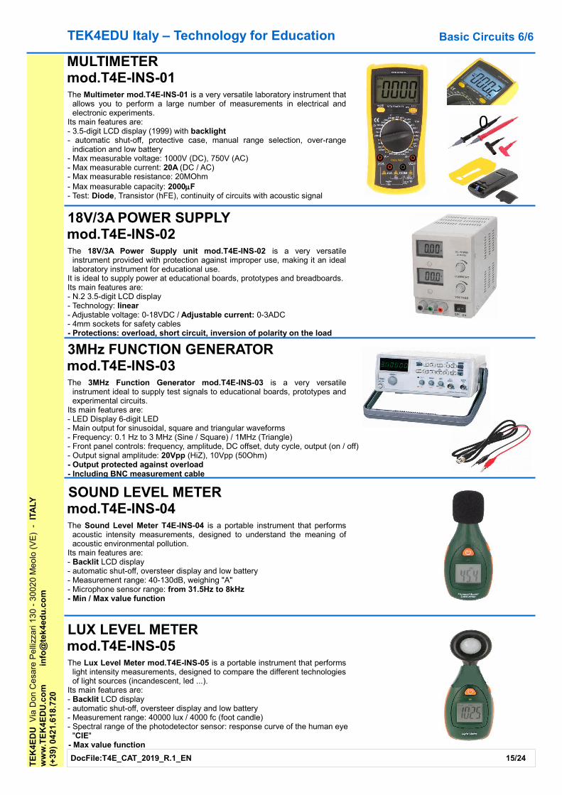
MULTIMETERmod.T4E-INS-01The Multimeter mod.T4E-INS-01 is a very versatile laboratory instrument that
allows you to perform a large number of measurements in electrical and electronic experiments.
Its main features are:- 3.5-digit LCD display (1999) with backlight- automatic shut-off, protective case, manual range selection, over-range
indication and low battery- Max measurable voltage: 1000V (DC), 750V (AC)- Max measurable current: 20A (DC / AC)- Max measurable resistance: 20MOhm- Max measurable capacity: 2000mF- Test: Diode, Transistor (hFE), continuity of circuits with acoustic signal
18V/3A POWER SUPPLYmod.T4E-INS-02The 18V/3A Power Supply unit mod.T4E-INS-02 is a very versatile
instrument provided with protection against improper use, making it an ideal laboratory instrument for educational use.
It is ideal to supply power at educational boards, prototypes and breadboards.Its main features are:- N.2 3.5-digit LCD display- Technology: linear- Adjustable voltage: 0-18VDC / Adjustable current: 0-3ADC- 4mm sockets for safety cables- Protections: overload, short circuit, inversion of polarity on the load
3MHz FUNCTION GENERATORmod.T4E-INS-03The 3MHz Function Generator mod.T4E-INS-03 is a very versatile
instrument ideal to supply test signals to educational boards, prototypes and experimental circuits.
Its main features are:- LED Display 6-digit LED- Main output for sinusoidal, square and triangular waveforms- Frequency: 0.1 Hz to 3 MHz (Sine / Square) / 1MHz (Triangle)- Front panel controls: frequency, amplitude, DC offset, duty cycle, output (on / off)- Output signal amplitude: 20Vpp (HiZ), 10Vpp (50Ohm)- Output protected against overload- Including BNC measurement cable
SOUND LEVEL METER mod.T4E-INS-04The Sound Level Meter T4E-INS-04 is a portable instrument that performs
acoustic intensity measurements, designed to understand the meaning of acoustic environmental pollution.
Its main features are:- Backlit LCD display- automatic shut-off, oversteer display and low battery- Measurement range: 40-130dB, weighing "A"- Microphone sensor range: from 31.5Hz to 8kHz- Min / Max value function
LUX LEVEL METERmod.T4E-INS-05The Lux Level Meter mod.T4E-INS-05 is a portable instrument that performs
light intensity measurements, designed to compare the different technologies of light sources (incandescent, led ...).
Its main features are:- Backlit LCD display- automatic shut-off, oversteer display and low battery- Measurement range: 40000 lux / 4000 fc (foot candle)- Spectral range of the photodetector sensor: response curve of the human eye
"CIE"- Max value function
TE
K4E
DU
Via
Don
Ce
sare
Pe
llizz
ari 1
30
- 3
002
0 M
eolo
(V
E)
-
ITA
LYw
ww
.TE
K4
ED
U.c
om
info
@te
k4e
du
.co
m(+
39)
04
21.6
18.
720
DocFile:T4E_CAT_2019_R.1_EN 15/24
Basic Circuits 6/6
0

TEK4EDU Italy – Technology for Education Educational Module 1/2
INSTRUMENTATION and LABORATORY ACCESSORIESLink: https://www.tek4edu.com/english/products/modules/
Link: https://www.tek4edu.com/english/products/kits-and-accessories/
These are the devices needed to set up the laboratory that will be used to perform electricity and electronic experiments.
They are educational modules (trainers) and useful accessories for each laboratory where you want to carry out electricity and electronic experiments, especially for technical / professional institutes.
To power experimental circuits, breadboards, Arduino boards or our simulators correctly, we offer the Educational Power supply module mod.T4E-MOD-01.
It supplies N.7 Voltage outputs (+ 15V, + 12V, + 5V, -15V, -12V, adjustable adjustable and negative adjustable) and N.1 Current output.
To supply the desired signals to the experimental circuits and breadboards (sine, square and impulsive waves) we propose the Educational Function generator module mod.T4E-MOD-10.
Both modules use a mC with code (included) that manages display, keyboard and relay, which is compatible with the Arduino Software IDE.
They can be interfaced directly to Arduino for coding exercises and allow the teaching of the power supply and the function generator.
In order to carry out experiments on breadboard we propose the Educational kit mod.T4E-ACC-01 which is complete with all the types of accessories and tools needed.
Educational Power SupplyMulti-Function Power Supply
mod.T4E-MOD-01
Educational GeneratorDDS Function Generator
mod.T4E-MOD-10
TE
K4E
DU
Via
Don
Ce
sare
Pe
llizz
ari 1
30
- 3
002
0 M
eolo
(V
E)
- I
TALY
ww
w.T
EK
4E
DU
.co
min
fo@
tek
4ed
u.c
om
(+3
9) 0
421
.61
8.7
20
Educational kitPrototype Kit
mod.T4E-ACC-01
DocFile:T4E_CAT_2019_R.1_EN 16/24
TEK4EDU Italy – Technology for Education Educational Module 2/2T
EK
4ED
U V
ia D
on C
esa
re P
elli
zzar
i 13
0 -
300
20
Meo
lo (
VE
) -
ITA
LYw
ww
.TE
K4
ED
U.c
om
info
@te
k4e
du
.co
m(+
39)
04
21.6
18.
720
DocFile:T4E_CAT_2019_R.1_EN 17/24
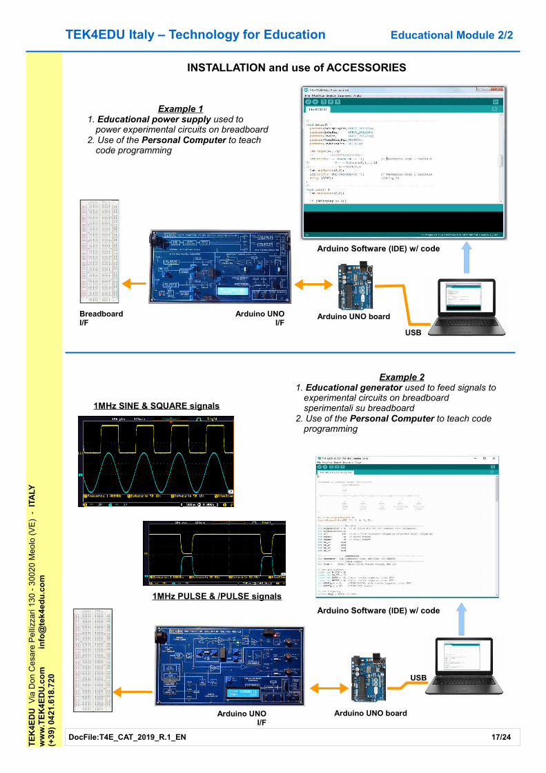
INSTALLATION and use of ACCESSORIES
BreadboardI/F
Arduino UNOI/F
Arduino UNO board
USB
Arduino Software (IDE) w/ code
Example 11. Educational power supply used to
power experimental circuits on breadboard2. Use of the Personal Computer to teach
code programming
Arduino UNOI/F
Arduino UNO board
USB
Arduino Software (IDE) w/ code
Example 21. Educational generator used to feed signals to
experimental circuits on breadboard sperimentali su breadboard
2. Use of the Personal Computer to teach code programming
1MHz SINE & SQUARE signals
1MHz PULSE & /PULSE signals

TEK4EDU Italy – Technology for EducationT
EK
4ED
U V
ia D
on C
esa
re P
elli
zzar
i 13
0 -
300
20
Meo
lo (
VE
) -
ITA
LYw
ww
.TE
K4
ED
U.c
om
info
@te
k4e
du
.co
m(+
39)
04
21.6
18.
720
DocFile:T4E_CAT_2019_R.1_EN 18/24
SHIELD for ARDUINO with BLUETOOTH and APPLink: https://www.tek4edu.com/english/products/arduino-shield/
Our shields are boards that fit on top of an Arduino UNO board.They have Bluetooth interface and App for communication with an Android device (smartphone or tablet).
They are a solution for the 1st level (Technology) / 2nd secondary school (Physics, Electronics, Computer Science and Telecommunications).
We propose the shield DDS Bluetooth Function Generator mod.T4E-ASB-01 to generate sinusoidal, square and impulsive waveform signals.
Together with the Arduino board it becomes a compact signal generator controlled via App (included) with settable frequency, from a few Hertz to a few MHz.
The signals generated can be supplied to:- experimental circuits and breadboards. For example by providing the sinusoidal signal to an audio amplifier,
you can check its frequency response or band, measure its output power at a given frequency, or perform other experiments.
- an oscilloscope, to show students how to use this instrument to perform measurements (amplitude, frequency, period, ...). Moreover if the instrument allows the FFT analysis it will be possible to show the characteristics of a periodic signal in the frequency domain.
We propose the shield EDU SHIELD mod.T4E- ASB-02 to teach Arduino coding and the MIT App Inventor 2 development environment with an electronic board ready for use and without having to prepare experimental circuits on breadboard and perform complex and often confusing wiring.
Allows you to perform 12 experiments. For each experiment the Arduino code and the App (if necessary) for communication between the shield and an Android device are provided.
It is only necessary to load the code (sketch) of the desired experiment that will allow to activate the transducer or read the status of a sensor or show on the display the desired information, etc.
It has 2 analogue interfaces (compatible with the BTA Vernier analog sensors).Using the HDMI Receiver (page 24) it is possible to replicate the same screen on the Android device on a large monitor, IWB or projector, facilitating the explanation to all students.
Both shields can have portable use if powered with a Power Bank.On our site the files for 3D printing of the storage box are available.
Arduino Shields 1/2
BT & DDS FUNCTION GENERATORmod.T4E-ASB-01
EDU SHIELDmod.T4E-ASB-02
Temperature probe
Remote RemoteMonitoring Control
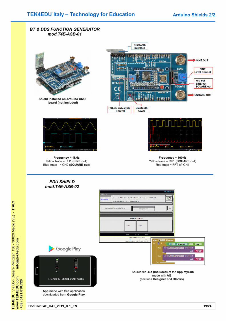
TEK4EDU Italy – Technology for Education
Shield installed on Arduino UNO board (not included)
TE
K4E
DU
Via
Don
Ce
sare
Pe
llizz
ari 1
30
- 3
002
0 M
eolo
(V
E)
-
ITA
LYw
ww
.TE
K4
ED
U.c
om
info
@te
k4e
du
.co
m(+
39)
04
21.6
18.
720
DocFile:T4E_CAT_2019_R.1_EN 19/24
Arduino Shields 2/2
BT & DDS FUNCTION GENERATORmod.T4E-ASB-01
Frequency = 1kHzYellow trace = CH1 (SINE out)
Blue trace = CH2 (SQUARE out)
Frequency = 100HzYellow trace = CH1 (SQUARE out)
Red trace = FFT of CH1
App made with free applicationdownloaded from Google Play
Source file .aia (included) of the App myEDU made with AI2
(sections Designer and Blocks)
EDU SHIELDmod.T4E-ASB-02

TEK4EDU Italy – Technology for Education Physics 1/3
TIMER – PHOTOGATE - ELECTROMAGNET Link: https://www.tek4edu.com/english/products/physics/
We have designed products for physics experiments with high performance and flexibility of use, which can be used with accessories (track or rail, electromagnet, ...) from other manufacturers.
The Timer mod.T4E-BOX-01 unit is a modern and compact time counter (chronometer) managed by a microcontroller that can directly manage an external electromagnet and from one up to three photogates with a resolution of 1/100000 sec (0.01ms).
It's available a Bluetooth version with Android App that allows simultaneous display of all data collected on a larger screen (smartphone or tablet).Using the HDMI Receiver (page 24) it is possible to replicate the same screen on the Android device on a large monitor, IWB or projector, facilitating the explanation to all students.
It can be used in experiments for the calculation of "g" or with use of track or rail.It has two operating modes (switch selectable): Manual and Automatic.
Manual: the electromagnet is powered and when the operator presses the green START button, the electromagnet is de-energized and the measurement starts. It is possible to connect from one to three photogates.
Automatic: the electromagnet is not powered and the measurement starts "automatically" (without pressing any key from the operator) when the object arrives at the first photogate. It is possible to connect two to three photogates: the first photogate is necessary to start the measurement.
In both manual and automatic modes it is possible to use the red STOP button to stop the measurement instead of the photogate. In this way it is possible to use the Timer for experiments in which photogates are not used, such as a manual stopwatch.
The unit measures both the time of arrival and the crossing time of the photogate, allowing the calculation of the speed of the object.
The display shows the information to allow the configuration of the measurement in step-by-step mode.Also information on the status of the power supply and activation of the protections are shown.The voltage available to power the electromagnet can be selected between +12VDC(1A) and +6VDC
(500mA). Other voltages are available upon request.
The Photogate mod.T4E-TAC-01 is supplied complete with support rod (D.10mm) and cable (L=1.5m).The Photogate stand mod.T4E-TAC-02 is an accessory of photogate.The "g" measurement kit mod.T4E-TAC-03 allows calculation of "g" and includes electromagnet, steel ball,
plexiglass tube (L=1m), stand and cable (L=1.5m).
TE
K4E
DU
Via
Don
Ce
sare
Pe
llizz
ari 1
30
- 3
002
0 M
eolo
(V
E)
-
ITA
LYw
ww
.TE
K4
ED
U.c
om
info
@te
k4e
du
.co
m(+
39)
04
21.6
18.
720
DocFile:T4E_CAT_2019_R.1_EN 20/24
TIMER CONNECTION DIAGRAM- Photogates with "in series" connection- Electromagnet powered by Timer
Android App myTIMER(only for Bluetooth version
mod.T4E-BOX-01-BT)
P.G. #1
P.G. #2
P.G. #3
+12VDC
E.M.
+6/+12VDC
L=1,5m (x3)
L=1,5m
TIMER

TEK4EDU Italy – Technology for Education Physics 2/3T
EK
4ED
U V
ia D
on C
esa
re P
elli
zzar
i 13
0 -
300
20
Meo
lo (
VE
) -
IT
ALY
ww
w.T
EK
4E
DU
.co
min
fo@
tek
4ed
u.c
om
(+3
9) 0
421
.61
8.7
20
DocFile:T4E_CAT_2019_R.1_EN 21/24
Measurements in MAN mode: start by pressing the START button
Measurements in AUTO mode: start the arrival of the object on the first photogate P.G.#1
START
P.G.#1 P.G.#2 P.G.#3
T=0
T1 w1
w2T2
w3T3
P.G.#1 P.G.#2 P.G.#3
T=0
w1
w2T21
w3T31
TIMER OPERATION MODE
Automatic mode (AUTO):The electromagnet is not powered.The measurement starts "automatically" (without the operator pressing any button) when the object arrives at the first
photogate.It is possible to connect from two to three photogates: first photogate is necessary to start the measurement.For example, with two photogates, the Timer measures:- the elapsed time from arrival to the first photogate (T=0) until the arrival at the second photogate (T21),- the crossing time of the first photogate (w1), e- the crossing time of the second photogate (w2).If the third photogate is also connected, the Timer also measures:- the time elapsed from arrival to the first photogate (T=0) until the arrival at the third photogate (T31), and- the crossing time of the third photogate (w3).
Manual mode (MAN):The electromagnet is powered.When the operator presses the green START button, the electromagnet is de-energized and the measurement starts.It is possible to connect from one to three photogates.The Timer measures:- the time elapsed from start-up (T=0) until arrival at the first photogate (T1), and- the crossing time of the first photogate (w1).Similar measurements will follow for the subsequent photogates.For example for the second photogate will be measured:- the time elapsed from start-up (T=0) to the arrival at the second photogate (T2), and- the crossing time of the second photo frame (w2).
TEK4EDU Italy – Technology for Education Physics 3/3T
EK
4ED
U V
ia D
on C
esa
re P
elli
zzar
i 13
0 -
300
20
Meo
lo (
VE
) -
IT
ALY
ww
w.T
EK
4E
DU
.co
min
fo@
tek
4ed
u.c
om
(+3
9) 0
421
.61
8.7
20
DocFile:T4E_CAT_2019_R.1_EN 22/24
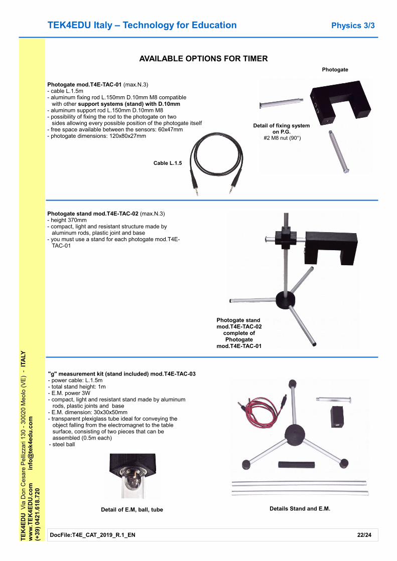
Detail of fixing systemon P.G.
#2 M8 nut (90°)
Photogate stand mod.T4E-TAC-02
complete ofPhotogate
mod.T4E-TAC-01
Photogate
Details Stand and E.M.
Photogate mod.T4E-TAC-01 (max.N.3)- cable L.1.5m- aluminum fixing rod L.150mm D.10mm M8 compatible
with other support systems (stand) with D.10mm- aluminum support rod L.150mm D.10mm M8- possibility of fixing the rod to the photogate on two
sides allowing every possible position of the photogate itself- free space available between the sensors: 60x47mm- photogate dimensions: 120x80x27mm
Photogate stand mod.T4E-TAC-02 (max.N.3)- height 370mm- compact, light and resistant structure made by
aluminum rods, plastic joint and base- you must use a stand for each photogate mod.T4E-
TAC-01
AVAILABLE OPTIONS FOR TIMER
"g" measurement kit (stand included) mod.T4E-TAC-03- power cable: L.1.5m- total stand height: 1m- E.M. power 3W- compact, light and resistant stand made by aluminum
rods, plastic joints and base- E.M. dimension: 30x30x50mm- transparent plexiglass tube ideal for conveying the
object falling from the electromagnet to the table surface, consisting of two pieces that can be assembled (0.5m each)
- steel ball
Detail of E.M, ball, tube
Cable L.1.5

TEK4EDU Italy – Technology for Education Medical devices 1/1
The Drop Buzzer mod.T4E-BOX-02 is a medical device that has been developed to be used by people with difficulties in visual perception (visually impaired or blind) to improve their autonomy during everyday life.
It's a complete kit, which contains (see main image):- an acoustic sensor for passing drops- a fixing system- an electric power supply- an adapter for the delivery system (syringe or flask)
Detects the passage of a drop of liquid and activates an internal buzzer.It works with colorless or colored liquids, with drops falling by a minimum diameter of 2.5 mm, which must pass
through the through hole on the device.At each passage of a drop, the audible beeper is activated, which emits a beep allowing the count of the drops
that have fallen into the container (or glass) present under the sensor.It can be used in two ways:- dropping the drops directly into the upper hole of the sensor (fig.A) or- using an adapter (fig.B), which will be inserted in the upper hole of the sensor, and will allow a simpler
centering of the drop of the drops to the whole of the sensor hole
DocFile:T4E_CAT_2019_R.1_EN 23/24
On request and free of charge, an adapter similar to the one shown in the figures (main and fig.B) made with a 3D printer will be provided.For the design and construction of the adapter, the dimensions of the delivery device to be used must be provided and be compatible with the characteristics of the hole on the sensor
TE
K4E
DU
Via
Don
Ce
sare
Pe
llizz
ari 1
30
- 3
002
0 M
eolo
(V
E)
-
ITA
LYw
ww
.TE
K4
ED
U.c
om
info
@te
k4e
du
.co
m(+
39)
04
21.6
18.
720
DROP BUZZERmod. T4E-BOX-02
Delivery system (not included)
Adapter
Sensor
Fixing system
Electric power supply
fig.A: hole of the sensor fig.B: adapter
TEK4EDU Italy – Technology for EducationT
EK
4ED
U V
ia D
on C
esa
re P
elli
zzar
i 13
0 -
300
20
Meo
lo (
VE
) -
IT
ALY
ww
w.T
EK
4E
DU
.co
min
fo@
tek
4ed
u.c
om
(+3
9) 0
421
.61
8.7
20
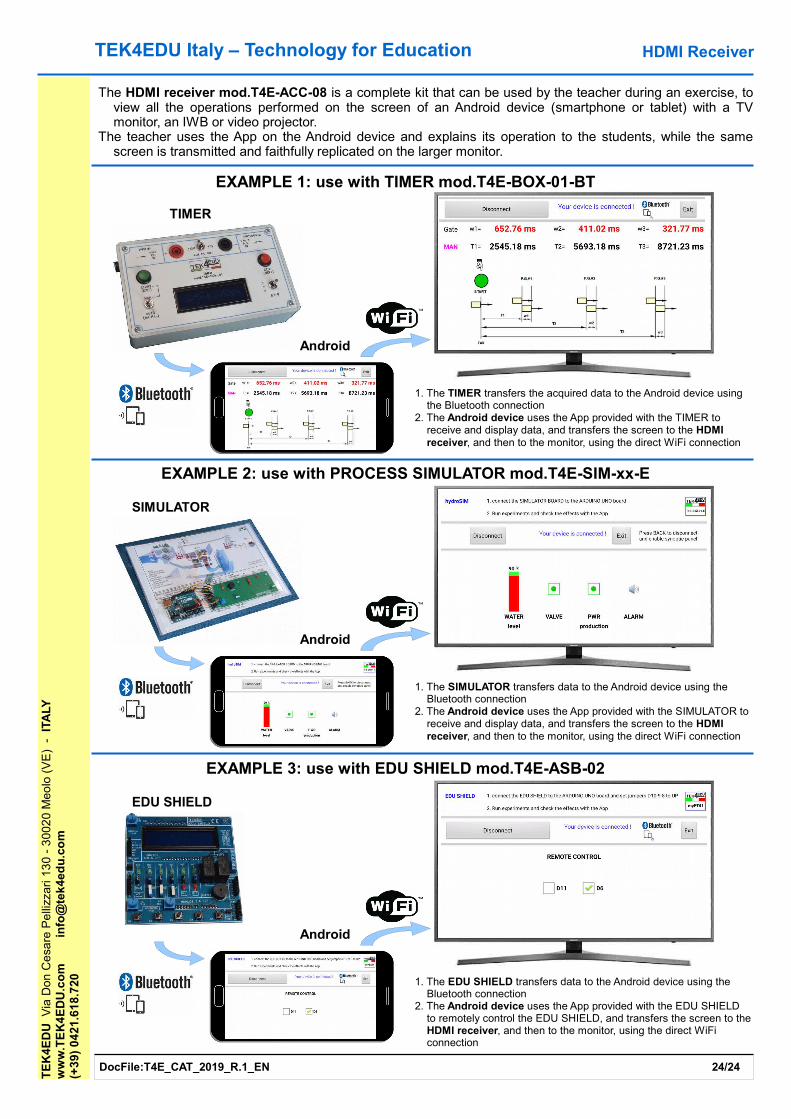
1. The TIMER transfers the acquired data to the Android device using the Bluetooth connection
2. The Android device uses the App provided with the TIMER to receive and display data, and transfers the screen to the HDMI receiver, and then to the monitor, using the direct WiFi connection
EXAMPLE 1: use with TIMER mod.T4E-BOX-01-BT
TIMER
Android
EXAMPLE 2: use with PROCESS SIMULATOR mod.T4E-SIM-xx-E
SIMULATOR
Android
1. The SIMULATOR transfers data to the Android device using the Bluetooth connection
2. The Android device uses the App provided with the SIMULATOR to receive and display data, and transfers the screen to the HDMI receiver, and then to the monitor, using the direct WiFi connection
EXAMPLE 3: use with EDU SHIELD mod.T4E-ASB-02
EDU SHIELD
Android
1. The EDU SHIELD transfers data to the Android device using the Bluetooth connection
2. The Android device uses the App provided with the EDU SHIELD to remotely control the EDU SHIELD, and transfers the screen to the HDMI receiver, and then to the monitor, using the direct WiFi connection
HDMI Receiver
The HDMI receiver mod.T4E-ACC-08 is a complete kit that can be used by the teacher during an exercise, to view all the operations performed on the screen of an Android device (smartphone or tablet) with a TV monitor, an IWB or video projector.
The teacher uses the App on the Android device and explains its operation to the students, while the same screen is transmitted and faithfully replicated on the larger monitor.
DocFile:T4E_CAT_2019_R.1_EN 24/24


