Download - Test Joints / Fixed Earthing Terminals
131
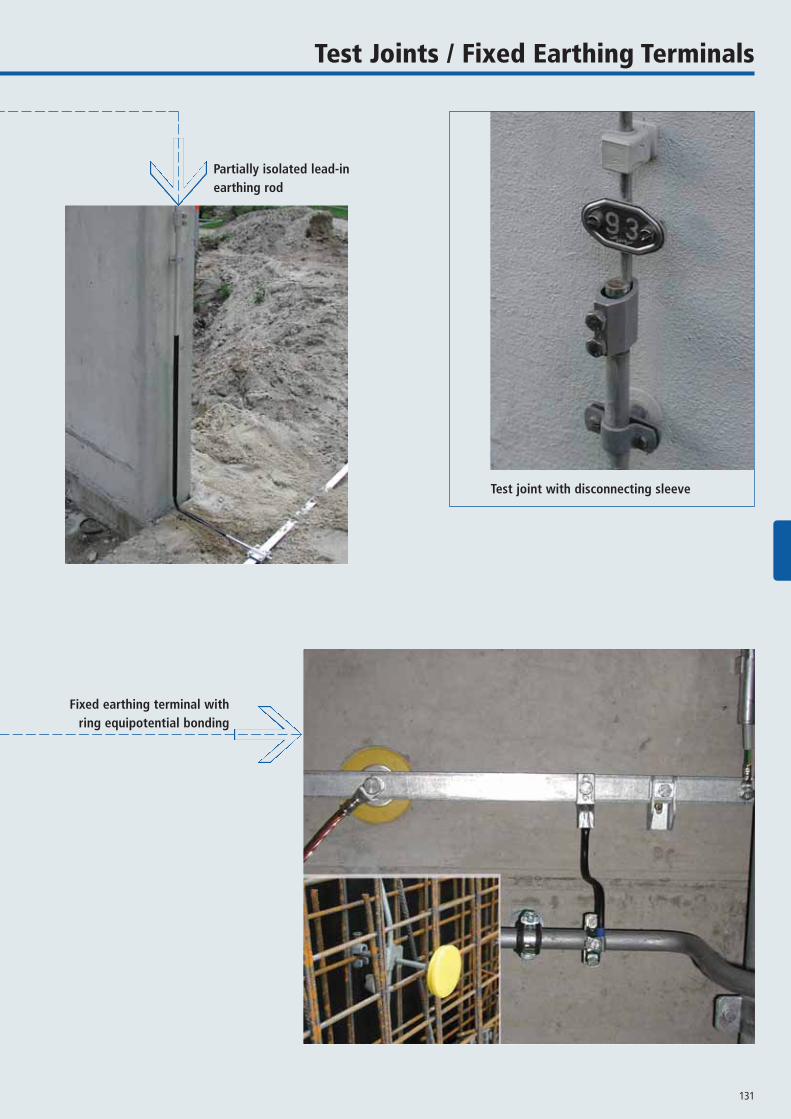
Test Joints / Fixed Earthing Terminals
Test joint with disconnecting sleeve
Partially isolated lead-inearthing rod
Fixed earthing terminal withring equipotential bonding

132
TEST JOINTSFIXED EARTHING TERMINALS
www.dehn.de
Disconnecting Sleeves
For connecting the down conductors with the earthentries
450 000450 007450 001
450 101450 011
A B C D
Clamping range Screw Screw PU PartMaterial Rd / Rd type material pc(s) No.
A MODELOpen unit for lead-in earthing rodsZDC 7-10 / 16 mm di M8x16 mm StSt (V2A) 50 450 000RCB 7-10 / 16 mm di M8x16 mm StSt (V2A) 50 450 007
B MODELOpen unit for lead-in earthing rodsAl 8-10 / 16 mm di M8x16 mm StSt (V2A) 50 450 001
C MODELClosed unit for wires Ø10 mmAl 8-10 / 8 mm di M8x16 mm StSt (V2A) 50 450 101
D MODELClosed unit for lead-in earthing rodsZDC 7-10 / 16 mm di M8x16 mm StSt (V2A) 50 450 011
A
B
C
D
tested tested tested tested
Tested according to DIN EN 50164-1(VDE 0185 Part 201): 2000-04tested
133
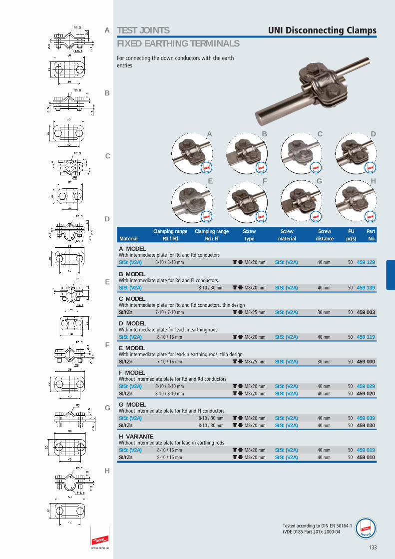
TEST JOINTSFIXED EARTHING TERMINALS
www.dehn.de
UNI Disconnecting Clamps
For connecting the down conductors with the earthentries
459 129459 139459 003459 119459 000459 029
459 020459 039459 030459 019459 010
A B C D
E F G H
Clamping range Clamping range Screw Screw Screw PU PartMaterial Rd / Rd Rd / Fl type material distance pc(s) No.
A MODELWith intermediate plate for Rd and Rd conductorsStSt (V2A) 8-10 / 8-10 mm di M8x20 mm StSt (V2A) 40 mm 50 459 129
B MODELWith intermediate plate for Rd and Fl conductorsStSt (V2A) 8-10 / 30 mm di M8x20 mm StSt (V2A) 40 mm 50 459 139
C MODELWith intermediate plate for Rd and Rd conductors, thin designSt/tZn 7-10 / 7-10 mm di M8x25 mm StSt (V2A) 30 mm 50 459 003
D MODELWith intermediate plate for lead-in earthing rodsStSt (V2A) 8-10 / 16 mm di M8x20 mm StSt (V2A) 40 mm 50 459 119
E MODELWith intermediate plate for lead-in earthing rods, thin designSt/tZn 7-10 / 16 mm di M8x25 mm StSt (V2A) 30 mm 50 459 000
F MODELWithout intermediate plate for Rd and Rd conductorsStSt (V2A) 8-10 / 8-10 mm di M8x20 mm StSt (V2A) 40 mm 50 459 029St/tZn 8-10 / 8-10 mm di M8x20 mm StSt (V2A) 40 mm 50 459 020
G MODELWithout intermediate plate for Rd and Fl conductorsStSt (V2A) 8-10 / 30 mm di M8x20 mm StSt (V2A) 40 mm 50 459 039St/tZn 8-10 / 30 mm di M8x20 mm StSt (V2A) 40 mm 50 459 030
H VARIANTEWithout intermediate plate for lead-in earthing rodsStSt (V2A) 8-10 / 16 mm di M8x20 mm StSt (V2A) 40 mm 50 459 019St/tZn 8-10 / 16 mm di M8x20 mm StSt (V2A) 40 mm 50 459 010
A
B
C
D
E
F
G
H
tested tested tested tested
tested tested tested tested
tested
Tested according to DIN EN 50164-1(VDE 0185 Part 201): 2000-04

134
TEST JOINTSFIXED EARTHING TERMINALS
www.dehn.de
ES Disconnecting Clamps
Single-screw unit
463 010
Clamping range Screw Screw/Nut PU PartMaterial Rd / Rd type material pc(s) No.
MCI/tZn 8 / 10 mm e M10x30 mm StSt (V2A) 50 463 010
ÖN Disconnecting Clamps
With connecting screw
460 213460 214
A B
Clamping range Screw Screw/Nut PU PartMaterial Rd / Rd type material pc(s) No.
A MODELFor solid round conductorsZDC 7-10 / 7-10 mm dj M6x12 / di M8x25 mm StSt (V2A) 50 460 213
B MODELFor lead-in earthing rodsZDC 7-10 / 16 mm dj M6x12 / di M8x25 mm StSt (V2A) 25 460 214
A
B
tested tested
tested
Tested according to DIN EN 50164-1(VDE 0185 Part 201): 2000-04tested

135
TEST JOINTSFIXED EARTHING TERMINALS
www.dehn.de
Connecting / Disconnecting Clamps
Two- or three-part connection system with threadedbase part
454 100454 107454 000
455 000
A B C
Clamping range Clamping range Screw PU PartMaterial Rd / Fl Fl / Fl Screw type material pc(s) No.
A MODELTwo-part unit for Rd / Fl conductorsSt/tZn 7-10 / 30-40 mm di M8x20 mm StSt (V2A) 25 454 100Cu 7-10 / 30-40 mm di M8x20 mm StSt (V2A) 25 454 107
B MODELThree-part unit (with intermediate plate) for Rd / Fl conductorsSt/tZn 5-10 / 30-40 mm di M8x30 mm StSt (V2A) 25 454 000
C MODELTwo-part unit for Fl / Fl conductorsMCI/tZn 30 / 30 mm di M8x25 mm StSt (V2A) 25 455 000
A
B
C
FIX Test Joints
With isolating unit and disconneting sleeve
453 100
Clamping range Screw Screw/Nut PU PartMaterial Rd / Fl type material Isolating unit pc(s) No.
St/tZn 8-10 / 30 mm di M8x16/M8x20 mm StSt (V2A) plastic1 10 453 100
Unit for Rd 8-10 and Rd 8-10 conductors available on request
tested tested tested
tested
tested
Tested according to DIN EN 50164-1(VDE 0185 Part 201): 2000-04
136
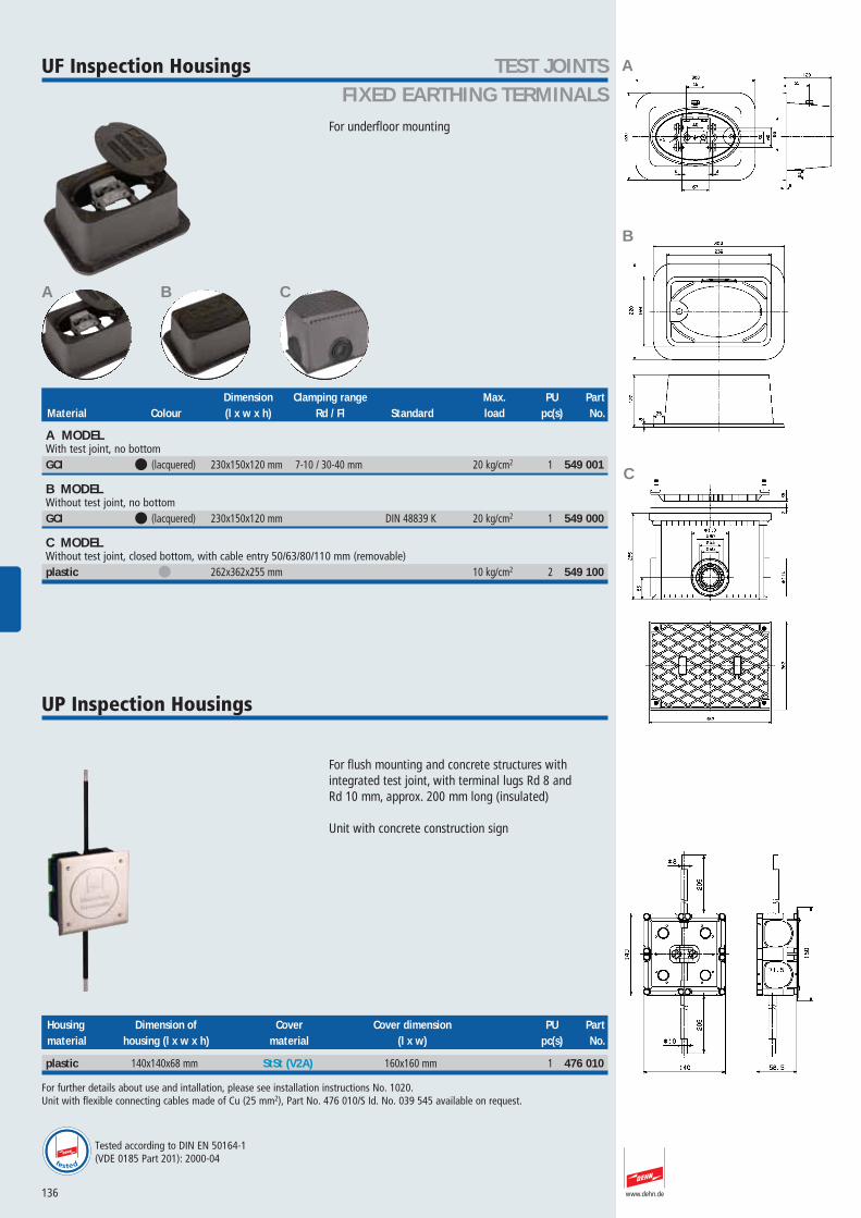
TEST JOINTSFIXED EARTHING TERMINALS
www.dehn.de
UF Inspection Housings
For underfloor mounting
549 001549 000
549 100
A B C
Dimension Clamping range Max. PU PartMaterial Colour (l x w x h) Rd / Fl Standard load pc(s) No.
A MODELWith test joint, no bottomGCI 1 (lacquered) 230x150x120 mm 7-10 / 30-40 mm 20 kg/cm2 1 549 001
B MODELWithout test joint, no bottomGCI 1 (lacquered) 230x150x120 mm DIN 48839 K 20 kg/cm2 1 549 000
C MODELWithout test joint, closed bottom, with cable entry 50/63/80/110 mm (removable)plastic 1 262x362x255 mm 10 kg/cm2 2 549 100
UP Inspection Housings
For flush mounting and concrete structures with integrated test joint, with terminal lugs Rd 8 and Rd 10 mm, approx. 200 mm long (insulated)
Unit with concrete construction sign
476 010
Housing Dimension of Cover Cover dimension PU Partmaterial housing (l x w x h) material (l x w) pc(s) No.
plastic 140x140x68 mm StSt (V2A) 160x160 mm 1 476 010
For further details about use and intallation, please see installation instructions No. 1020. Unit with flexible connecting cables made of Cu (25 mm2), Part No. 476 010/S Id. No. 039 545 available on request.
A
B
C
Tested according to DIN EN 50164-1(VDE 0185 Part 201): 2000-04tested

137
TEST JOINTSFIXED EARTHING TERMINALS
www.dehn.de
Inspection Doors
For flush-mounted test joints
476 020476 001
Mounting Dimension Based on PU PartMaterial dimension (l x w) (l x w) standard pc(s) No.
A MODELStSt unit for screwing (hole Ø8-10 mm), with removable door and square spannerStSt (V2A) 205x145 mm 285x225 mm DIN 48839 1 476 020
B MODELLight unit for immuring/plastering, with claws (length: 60 mm, distance: 100 mm), with square spannerSt/tZn 205x155 mm 230x180 mm 10 476 001
B
A
A B
138
TEST JOINTSFIXED EARTHING TERMINALS
www.dehn.de
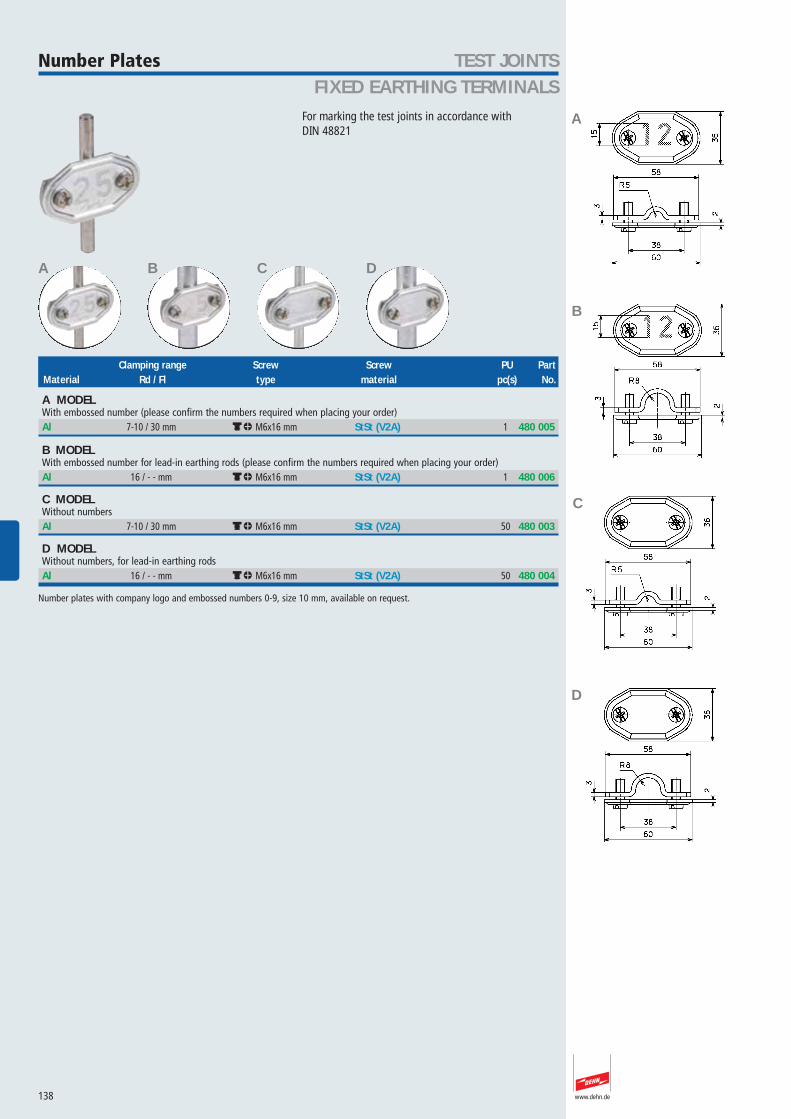
Number Plates
For marking the test joints in accordance with DIN 48821
480 005480 006480 003
480 004
A B C D
Clamping range Screw Screw PU PartMaterial Rd / Fl type material pc(s) No.
A MODELWith embossed number (please confirm the numbers required when placing your order)Al 7-10 / 30 mm dm M6x16 mm StSt (V2A) 1 480 005
B MODELWith embossed number for lead-in earthing rods (please confirm the numbers required when placing your order)Al 16 / - - mm dm M6x16 mm StSt (V2A) 1 480 006
C MODELWithout numbersAl 7-10 / 30 mm dm M6x16 mm StSt (V2A) 50 480 003
D MODELWithout numbers, for lead-in earthing rodsAl 16 / - - mm dm M6x16 mm StSt (V2A) 50 480 004
Number plates with company logo and embossed numbers 0-9, size 10 mm, available on request.
A
B
C
D

New Products 139
TEST JOINTSFIXED EARTHING TERMINALS
www.dehn.de
Support for VDB Test Badge480 113480 114
480 110
A
Clamping range Screw Cleat Dimension PU PartMaterial Rd / Fl Screw type material material (l x w x d) pc(s) No.
A MODELFor Rd 7-10 and Fl 30 mm conductors StSt (V2A) 7-10 / 30 mm dm M6x16 mm StSt (V2A) StSt (V2A) 84x58x1 mm 50 480 113
B MODELFor Rd 16 mm lead-in earthing rodsStSt (V2A) 16 / - - mm dm M6x16 mm StSt (V2A) StSt (V2A) 84x58x1 mm 50 480 114
C MODELWithout cleatStSt (V2A) 84x58x1 mm 50 480 110
Set of Lead-in Earthing Rods
Complete with disconnecting sleeve and terminals (KS screws)
480 150480 175
480 157
A B
Length KS screw Sleeve PU PartMaterial Standard (l1) connection Rd connection Rd / Rd pc(s) No.
A MODELSt/tZn with disconnecting sleeve (Part No. 450 000) and KS screws (Part No. 300 000)St/tZn DIN EN 50164-2 1500 mm 7-10 mm 7-10 / 16 mm 1 480 150St/tZn DIN EN 50164-2 1750 mm 7-10 mm 7-10 / 16 mm 1 480 175
B MODELCu with disconnecting sleeve (Part No. 450 007) and KS screws (Part No. 300 007)Cu DIN EN 50164-2 1500 mm 6-10 mm 7-10 / 16 mm 1 480 157
B C
A / B
C
B
N
N
N
N
A

140
TEST JOINTSFIXED EARTHING TERMINALS
www.dehn.de
Lead-in Earthing Rods
For connecting the down conductors with the earth-termination system
483 150483 200104 903104 905104 906101 150479 150
479 157480 018480 019480 020480 021480 022
A B C D
Length Hole Partial length Partial length PU PartMaterial Standard Diameter (l1) distance Ø16 mm (l2) Ø10 mm (l3) pc(s) No.
A MODELChamfered on both sidesSt/tZn DIN EN 50164-2 16 mm 1500 mm 10 483 150St/tZn DIN EN 50164-2 16 mm 2000 mm 10 483 200StSt (V4A) DIN EN 50164-2 16 mm 1000 mm 10 104 903StSt (V4A) DIN EN 50164-2 16 mm 1500 mm 10 104 905StSt (V4A) DIN EN 50164-2 16 mm 2000 mm 10 104 906
B MODELWith welded flat tap (hole Ø11 mm)St/tZn DIN EN 50164-2 16 mm 1500 mm 22 mm 10 101 150
C MODELWith welded tap for e.g. 2 KS screws (not included in delivery)St/tZn DIN EN 50164-2 16 mm 1500 mm 30 mm 10 479 150Cu DIN EN 50164-2 16 mm 1500 mm 30 mm 10 479 157
D MODELDiminished (notched conductor Ø10 mm), partly insulated (length approx. 700 mm)St/tZn DIN EN 50164-2 16/10 mm 1500 mm 1000 mm 500 mm 10 480 018St/tZn DIN EN 50164-2 16/10 mm 1750 mm 750 mm 1000 mm 10 480 019St/tZn DIN EN 50164-2 16/10 mm 2000 mm 1000 mm 1000 mm 10 480 020St/tZn DIN EN 50164-2 16/10 mm 2500 mm 1500 mm 1000 mm 10 480 021St/tZn DIN EN 50164-2 16/10 mm 2250 mm 1250 mm 1000 mm 10 480 022
A
B
D
C
141
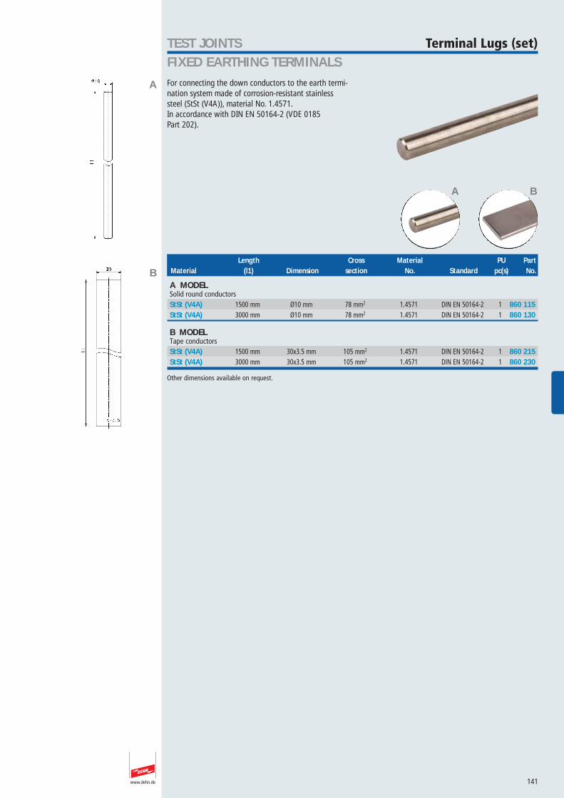
TEST JOINTSFIXED EARTHING TERMINALS
www.dehn.de
Terminal Lugs (set)
For connecting the down conductors to the earth termi-nation system made of corrosion-resistant stainlesssteel (StSt (V4A)), material No. 1.4571.In accordance with DIN EN 50164-2 (VDE 0185 Part 202).
860 115860 130860 215
860 230
A B
Length Cross Material PU PartMaterial (l1) Dimension section No. Standard pc(s) No.
A MODELSolid round conductorsStSt (V4A) 1500 mm Ø10 mm 78 mm2 1.4571 DIN EN 50164-2 1 860 115StSt (V4A) 3000 mm Ø10 mm 78 mm2 1.4571 DIN EN 50164-2 1 860 130
B MODELTape conductorsStSt (V4A) 1500 mm 30x3.5 mm 105 mm2 1.4571 DIN EN 50164-2 1 860 215StSt (V4A) 3000 mm 30x3.5 mm 105 mm2 1.4571 DIN EN 50164-2 1 860 230
Other dimensions available on request.
B
A

142
TEST JOINTSFIXED EARTHING TERMINALS
www.dehn.de
Fixed Earthing Terminals
For connection with the reinforcement of buildings, con-necting point for down conductors (earth terminationsystem), also measuring point (transient/resistance test)at the same timeNote:For connections M10 and M12, the screws used musthave the following minimum lengths:M10: 35 mm (thread length 40 mm)M12: 15 mm (thread length 20 mm)
– Allows for connection at the terminal axis with across unit, e.g. Part No. 319 201, or connecting termi-nal, e.g. Part No. 308 025, for the reinforcement
– Using 2 fixed earthing terminals, a wall duct (adjust-able to wall thicknesses of up to 360 mm) can beinstalled with a parallel connector, Part No. 306 020,for connection on both sides of earth conductors
– Allows for connection of an equipotential bondingbar, e.g. sealing units, Part Nos. 363 001, 390 479,390 489,
– Allows for connection of flat conductors at the con-necting plate (front) or without terminal axis (back),e.g terminal, Part No. 478 141
– Screwable or compressed terminal axis
– Snap-on (yellow) plastic cover
478 011478 019478 012478 200478 041
478 049478 241478 249
A B C D E
Terminal Plate Axis Connecting PU Partthread (d1) material material plate Ø pc(s) No.
A MODELType M with terminal axis (l= 195 mm, Ø10 mm)M10 / 12 StSt (V4A) St/tZn 80 mm 10 478 011M10 / 12 StSt (V4A) StSt (V2A) 80 mm 10 478 019
B MODELType M without terminal axisM10 / 12 StSt (V4A) 80 mm 10 478 012
C MODELType K with plastic ring and terminal axis (l= 195 mm, Ø10 mm)M10 / 12* StSt (V4A) St/tZn 47 mm 10 478 200
*tested with 50 Hz currents.
D MODELType M with compressed terminal axis (l= 180 mm, Ø10 mm)M10 /12 StSt (V4A) St/tZn 80 mm 10 478 041M10 / 12 StSt (V4A) StSt (V2A) 80 mm 10 478 049
E MODELType K with compressed terminal axis (l= 180 mm, Ø10 mm)M10 /12 StSt (V4A) St/tZn 47 mm 10 478 241M10 / 12 StSt (V4A) StSt (V2A) 47 mm 10 478 249
For further details on use and installation, please see installation instructions No. 1476.
A
B
D
E
tested tested tested tested
C
tested
Tested according to DIN EN 50164-1(VDE 0185 Part 201): 2000-04tested

143
TEST JOINTSFIXED EARTHING TERMINALS
www.dehn.de
Sealing Units
For screwing to the fixed earthing terminal for connec-tion of e.g. an equipotential bonding barFor connecting parts of the construction (e.g. steel supports, or suchlike) by screwing or welding
390 489390 479363 001363 010
363 000390 450390 459
A B C D E F
Hole Hole Clamping Screw Screw/Nut PU PartMaterial distance Ø range Rd type material pc(s) No.
A MODELWith square holes 11x11 mm, for connection of Rd conductors, e.g. with KS connector (Part No. 301 019), or for connection of Fl conductors with M10 screws and nutsStSt (V2A) 30 mm square hole 11 mm 50 390 489
B MODELWith square holes 11x11 mm, for connection of Rd conductors, e.g. with KS connector (Part No. 301 019), or for connection of Fl conductors with M10 screws and nutsStSt (V2A) 30 mm 13 mm 50 390 479
C MODELWithout connecting holes, for connection of Rd and Fl conductors, e.g. by isolating clamp, Part No. 454 100 and 455 000St/tZn 13 mm 50 363 001
D MODELWith connecting holes Ø11 mm and KS connectorSt/tZn 22 mm 11 mm 7-10 mm 50 363 010
E MODELWith connecting holes Ø11 mm, without KS connectorSt/tZn 22 mm 11 mm 50 363 000
F MODELWith square holes 11x11 mm and double cleatSt/tZn 30 mm square hole 11 mm 8-10 mm di M8x30 mm StSt (V2A) 50 390 450StSt (V2A) 30 mm square hole 11 mm 8-10 mm di M8x30 mm StSt (V2A) 50 390 459
B
C
D
E
F
A
tested tested
tested
Tested according to DIN EN 50164-1(VDE 0185 Part 201): 2000-04

144
TEST JOINTSFIXED EARTHING TERMINALS
www.dehn.de
Connecting Terminalswith threaded bolt
For connecting Rd and Fl conductors to fixed earthingterminals with M10/M12 thread (e.g. Part Nos. 478 011,478 200)Can also be mounted on the back side of the fixedearthing terminal without terminal axis, e.g. for flatstripTerminal thread: M10
478 141
Bushing for Roofs, Walls and Earthing Electrodes
For water-proof and presswater-proof duct of walls andflat roofs (against stagnant water), with threaded M12rod made of StSt (V2A)
478 310478 320478 330
478 340
Clamp Clamping range Bolt Screw Screw/Nut Dimension PU Partmaterial Rd / Fl material type material (l x w x t1/t2) pc(s) No.
St/tZn 7-10 / 30-40 mm StSt (V2A) di M10x45, M8x25 mm StSt (V2A) 70x70x4 mm 10 478 141
Lead-through Length of Sealing Plate PU Partlength (l2) threaded rod (l1) Sealings plate Ø material pc(s) No.
100-200 mm 300 mm chloropren rubber 80 mm StSt (V4A) 1 478 310200-300 mm 400 mm chloropren rubber 80 mm StSt (V4A) 1 478 320300-400 mm 500 mm chloropren rubber 80 mm StSt (V4A) 1 478 330400-600 mm 700 mm chloropren rubber 80 mm StSt (V4A) 1 478 340
For further details, please see installation instructions No. 1332.
tested
Tested according to DIN EN 50164-1(VDE 0185 Part 201): 2000-04tested


