
TeSys model UMotor starters - open version
06CatalogueJanuary


1
General contents TeSys model U Motor starters - open version
1 – TeSys model UMotor starters - open version
2 – Altistart U01 soft starters and TeSys model U

1/0
1

1/1
Contents 0
1
1 - TeSys model UMotor starters - open version
Selection guide . . . . . . . . . . . . . . . . . . . . . . . . . . . . . . . . . . . . . pages 1/2 and 1/3
b Presentation . . . . . . . . . . . . . . . . . . . . . . . . . . . . . . . . . . . . . . . . pages 1/4 to 1/7
b Application examples. . . . . . . . . . . . . . . . . . . . . . . . . . . . . . . . . pages 1/8 to 1/13
b Reversing and non-reversing power bases . . . . . . . . . . . . . pages 1/14 and 1/15
b Add-on contact blocks and auxiliary contact modules . . . . . . . . . . . . . . page 1/16
b Power connection pre-wired system . . . . . . . . . . . . . . . . . . . . . . . . . . . page 1/17
b Control units, multifunction control units and
function modules . . . . . . . . . . . . . . . . . . . . . . . . . . . . . . . . . . . pages 1/18 to 1/21
b PowerSuite software workshop . . . . . . . . . . . . . . . . . . . . . . . . pages 1/22 to 1/25
b Model U controllers . . . . . . . . . . . . . . . . . . . . . . . . . . . . . . . . . pages 1/26 to 1/29
b Parallel wiring module and
pre-wired coil connection components . . . . . . . . . . . . . . . . . pages 1/30 and 1/31
b AS-Interface cabling system :
dedicated components . . . . . . . . . . . . . . . . . . . . . . . . . . . . . pages 1/32 and 1/33
b Modbus communication modules and
pre-wired coil connection components . . . . . . . . . . . . . . . . . pages 1/34 and 1/35
b Communication gateways LUF P . . . . . . . . . . . . . . . . . . . . . pages 1/36 and 1/37
b Characteristics . . . . . . . . . . . . . . . . . . . . . . . . . . . . . . . . . . . . . pages 1/38 to 1/45
b Curves . . . . . . . . . . . . . . . . . . . . . . . . . . . . . . . . . . . . . . . . . . . pages 1/46 to 1/49
b Selection guide . . . . . . . . . . . . . . . . . . . . . . . . . . . . . . . . . . . pages 1/50 and 1/51
b Dimensions . . . . . . . . . . . . . . . . . . . . . . . . . . . . . . . . . . . . . . pages 1/52 and 1/53
b Schemes . . . . . . . . . . . . . . . . . . . . . . . . . . . . . . . . . . . . . . . . . pages 1/54 to 1/61
b Basic schemes . . . . . . . . . . . . . . . . . . . . . . . . . . . . . . . . . . . . pages 1/62 to 1/65

1/2
1
Selection guide 1 TeSys motor starters - open version 1
Selectable overload class
Detection of overtorque, no-load running, long starting timesEarth fault protection (equipment protection only)
Protection against phase imbalanceProtection against phase loss
Fault differentiation With contact block
Reset on thermal overload Manual or automatic
Manual Manual or automatic Manual
Alarms (thermal overload, overcurrent, ...)
Indication of motor load
Protection function parameter entry"Log" function, monitoring
Remote motor starter status and commands via serial or parallel link
Motor starter management via serial link (status, commands, selection and parameter entry for alarms, log, monitoring)
Modbus port built-in
Isolation function
Protection against overloads and short-circuits
Power at 400 V With circuit-breaker 0.06…75 kW 30…450 kW 0.06…450 kW 0.06…110 kW
With fuses 0.06…75 kW 30…450 kW 0.06…450 kW
Magnetic circuit-breaker or fuses
Magnetic circuit-breakeror fuses
Magnetic circuit-breakeror fuses
Thermal magnetic circuit-breaker
Contactor Contactor Contactor Contactor
Thermal overload relay
Electronic thermal overload relay
Multifunction protection relay
Function performed Function not performed

1/3
1
11
With function module Indication on front panel,processing by communication
Manual Remote or automatic with function module Reset parameters can be set to manual or automatic
With function module Indication on front panel,processing by communication
With function module Indication on front panel,processing by communication
Indication on front panel, processing by communication
With communication module or control splitter box
With AS-Interface or Modbus communication module
With AS-Interface or Modbus communication module(indication of motor load and thermal overload alarm only with Modbus communication module)
(1) (1) (1)
With Modbus communication module
0.06…11 kW 0.06…15 kW 0.06…15 kW 16.5…450 kW 0.06…15 kW 16.5…450 kW
0.06…450 kW 0.06…450 kW
Quickfit solution Starter-controller with standard control unit
Starter-controller with advanced control unit
Magneticcircuit-breaker or fuses
Starter-controller with multifunction control unit
Magneticcircuit-breaker or fuses
Contactor Contactor
Controller with advanced control unit
Controller with multifunction control unit
(1) Parallel wiring module

1/4
1
Presentation 1 TeSys motor starters - open version 1
Model U starter-controllers
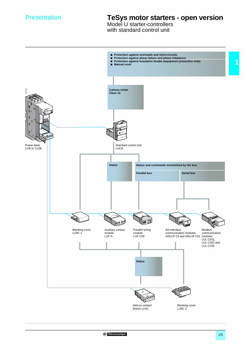
PresentationThe TeSys model U starter controller is a D.O.L. starter (1) which performs the following functions:b protection and control of single-phase or 3-phase motors:v breaking function,v overload and short-circuit protection,v thermal overload protection and power switching,b control of the application: v protection function alarms,v application monitoring (running time, number of faults, motor current values, ...),v logs (last 5 faults saved, together with motor parameter values).
These functions can be added by selecting control units and function modules which simply clip into the power base. The product can therefore be customised at the last moment. Setting-up accessories simplify or completely eliminate wiring between components.
Basic starter-controllerConsists of a power base and a control unit. Power base
Is independent of the control voltage and of the motor power.It incorporates the breaking function with a breaking capacity of 50 kA at 400 V, total coordination (continuity of service) and the switching function.b 2 ratings are available: 0…12 A and 0…32 A.b Non-reversing (LUB) and reversing (LU2B). Control units
These must be selected according to the control voltage, the power of the motor to be protected and the type of protection required.b Standard control unit (LUCA): satisfies the basic protection requirements for motor starters:
thermal overload and short-circuit (for details see page 1/5).b Advanced control unit (LUCB, LUCC or LUCD): allows additional advanced functions such
as alarm, fault differentiation, … (for details see page 1/6).b Multifunction control unit (LUCM): suitable for the most sophisticated control and protection
requirements (for details see page 1/7). The control units are interchangeable without rewiring and without using tools. They have a wide range of adjustment (range of 4) and low heat dissipation.
Control optionsFunction modules can be used to increase the functions of the starter-controller.Function modules
Must be used with advanced control units. 4 types are available:b thermal overload alarm (LUF W10),b thermal fault and manual reset (LUF DH11),b thermal fault and automatic or remote reset (LUF DA01 and LUF DA10),b indication of motor load (LUF V), which can also be used with the multifunction control unit.
All alarm and fault information processed by these modules is available on digital contacts.
Communication modules The information processed is exchanged:b via a parallel bus:v parallel wiring module (LUF C00),b via a serial bus:v AS-Interface modules (ASILUF C5 and ASILUF C51),v Modbus modules (LUL C031, LUL C032 and LUL C033).
They must be used in conjunction with a c 24 V control unit and require a c 24 V control voltage. Connection to other protocols such as FIPIO, Profibus-DP and DeviceNet is possible via gateway modules (LUFP).Auxiliary contact modules (LUFN)
3 possible configurations 2 N/O, 1 N/O + 1 N/C or 2 N/C.Add-on contact blocks
Indicate the following status of power base: ready, fault and pole status.
Power optionsReverser block
Allows a non-reversing power base to be converted to reversing operation.The reverser block (LU2M) is mounted directly beneath the power base without modifying the width of the product (45 mm). The reverser block LU6M is mounted separately from the power base when the height available is limited.Limiter-disconnector LUA LB
This unit is mounted directly on the power base. It allows the breaking capacity to be increased up to 130 kA at 400 V.
Setting-up accessoriesPlug-in terminal blocks
The control terminal blocks are of the plug-in type, so allowing wiring to be prepared away from the machine or the replacement of products without rewiring.Control circuit pre wiring system
Numerous pre-wired accessories provide simple, clip-in connections (e.g. connection of reverser control terminals, ...(1) For use with resistive and inductive loads. Control of d.c. or capacitive loads is not possible.
6
5
7
1
2
3
4
8
5212
88
1
2
3
3
3
4
5
6
7
8
1/5
1
Presentation 1 TeSys motor starters - open version 1
Model U starter-controllers with standard control unit
Power baseLUB or LU2B
3-phase motorClass 10
Status and commands transmitted by the bus
Blanking coverLU9C 1
Modbuscommunication modulesLUL C031, LUL C032 and LUL C033
Standard control unitLUCA
AS-Interface communication modulesASILUF C5 and ASILUF C51
Auxiliary contact moduleLUF N
Parallel wiring moduleLUF C00
Add-on contact blocks LUA1
Parallel bus Serial bus
Status
Blanking coverLU9C 2
Status
b Protection against overloads and short-circuitsb Protection against phase failure and phase imbalance b Protection against insulation breaks (equipment protection only)b Manual reset
5207
26

1/6
1
Presentation 1 TeSys motor starters - open version 1
Model U starter-controllerswith advanced control unit
3-phase motorClass 10
3-phase motorClass 20
Single-phase motorClass 10
Thermal overload signalling and manual reset
Thermal overload signalling and automatic reset
Alarm Indication of motor load (analogue)
Status and commands transmitted by the bus
b Thermal overload signalling and manual, remote or automatic reset
b Alarmb Indication of motor
load
Auxiliary contact moduleLUF N
Function moduleLUF DH11
Function modulesLUF DA01 and UF DA10
Function moduleLUF W10
Function moduleLUF V
Power baseLUB or LU2B
Advanced control unit LUCB
Advanced control unit LUCD
Advanced control unit LUCC
b Protection against overloads and short-circuitsb Protection against phase failure and phase imbalance b Protection against insulation breaks (equipment protection only)b Manual reset (remote or automatic with a function module)
Modbus communication modulesLUL C031, LUL C032 and LUL C033
Blanking cover LU9C 1
Add-on contact blocks LUA1
Parallel bus Serial bus
Status
Blanking cover LU9C 2
AS-Interface communication modulesASILUF C5 and ASILUF C51
Parallel wiring moduleLUF C00
Status
5338
42

1/7
1
Presentation 1 TeSys motor starters - open version 1
Model U starter-controllers with multifunction control unit
Blanking coverLU9C 1
b Protection against overloads and short-circuitsb Protection against phase failure and phase imbalance b Protection against insulation breaks (equipment protection only)b Reset parameters can be set to manual or automaticb Protection function alarm b Indication on front panel or on remote terminal via Modbus RS 485 portb "Log" functionb "Monitoring" function, indication of main motor parameters on front panel of the
control unit or via a remote terminalb Fault signallingb Overtorque, no-load running
Single-phase or 3-phase motorsClass 5, 10, 15, 20, 25, 30
Indication of motor load (analogue)
Status and commands transmitted by the bus
Remote programming and monitoring of all functions
Power baseLUB or LU2B
Multifunction control unitLUCM
Function moduleLUF V
AS-Interface communication modulesASILUF C5 and ASILUF C51
Aduxiliary contact moduleLUF N
Add-on contact blocksLUA1
Modbus communication modulesLUL C031, LUL C032 and LUL C033
Parallel wiring moduleLUF C00
Blanking coverLU9C 2
Status
Parallel bus Serial bus
Status
5653
97

1/8
1
Application examples 1 TeSys motor starters - open version 1
Model U starter-controllers
Starting and protection of a pump.
b Power: 4 kW at 400 V.b In: 9 A.b Maximum of 10 class 10 starts per hour.b Duty class S3.b 3-wire control:v Start button (S2),v Stop button (S1),b Control circuit voltage: a 230 V.
b Short-circuit protection with level of protection of 50 kA at 400 V.b Total coordination of protection devices conforming to EN 60947-6-2 (continuity of service) in case of a short-circuit.b Electronic protection against thermal overloads with an adjustment range of 4.b Load switching (2 million operating cycles in category AC-43 at In).b Indication of motor status by N/C or N/O contact.b Interlock between the motor starter control and the selector knob position; not possible to start the motor when the knob is in the OFF position.
Application
Operating conditions
Products used
5209
65
Products used Item Quantity Reference PagePower base 12 A with screw clamp connections
1 1 LUB 12 1/14
Standard control unit 2 1 LUCA 12FU 1/19
Functions performed
Scheme
5616
80
1/L1
3/L2
5/L3
2/T
1
4/T
2
6/T
3
A2
A1
1314
–
M3
230 V
U1
V1
W1
C.U.
1/9
1
Application examples 1 TeSys motor starters - open version 1
Model U starter-controllers
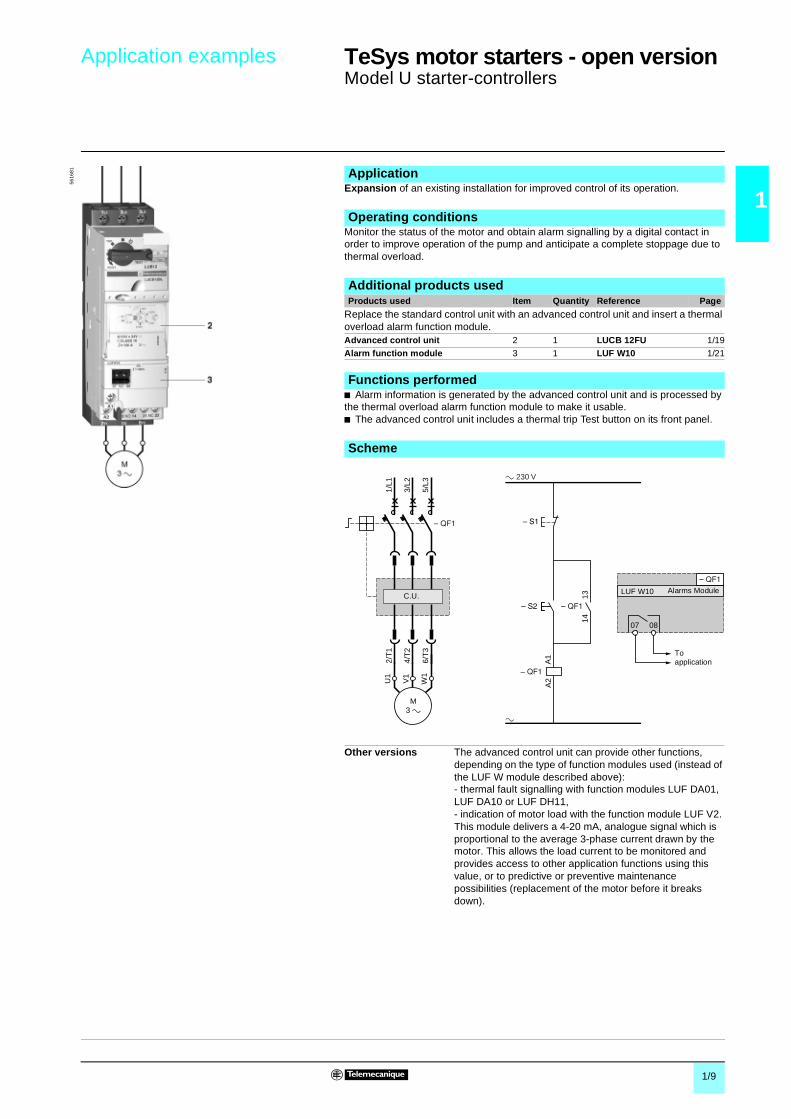
Expansion of an existing installation for improved control of its operation.
Monitor the status of the motor and obtain alarm signalling by a digital contact in order to improve operation of the pump and anticipate a complete stoppage due to thermal overload.
b Alarm information is generated by the advanced control unit and is processed by the thermal overload alarm function module to make it usable.b The advanced control unit includes a thermal trip Test button on its front panel.
Application
Operating conditions
Additional products used
5616
81
Products used Item Quantity Reference Page
Replace the standard control unit with an advanced control unit and insert a thermal overload alarm function module.Advanced control unit 2 1 LUCB 12FU 1/19
Alarm function module 3 1 LUF W10 1/21
Functions performed
Scheme
Other versions The advanced control unit can provide other functions, depending on the type of function modules used (instead of the LUF W module described above):- thermal fault signalling with function modules LUF DA01, LUF DA10 or LUF DH11,- indication of motor load with the function module LUF V2. This module delivers a 4-20 mA, analogue signal which is proportional to the average 3-phase current drawn by the motor. This allows the load current to be monitored and provides access to other application functions using this value, or to predictive or preventive maintenance possibilities (replacement of the motor before it breaks down).
LUF W10
1/L1
3/L2
5/L3
2/T
1
4/T
2
6/T
3
A2
A1
1314
–
M3 a
a 230 V
a
U1
V1
W1
07 08
C.U.
To application
Alarms Module

1/10
1
Application examples 1 TeSys motor starters - open version 1
Model U starter-controllers
Monitoring operation of a surface pump in a water treatment plant to avoid running empty, which could lead to destruction of the pump.
b Power: 15 kW at 400 V.b In: 28.5 A.b Duty class S1.b Control circuit voltage: c 24 V.b Control-command by PLC and serial link using the Modbus protocol.
b Short-circuit protection with level of protection of 50 kA at 400V.b Total coordination of protection devices conforming to EN 60947-6-2 (continuity of service) in case of a short-circuit.b Electronic protection against thermal overloads with an adjustment range of 4.b Load ing (1.5 million operating cycles in category AC-43 at In).b Measurement of load current and detection of no-load running by the multifunction control unit.b Interlock between the motor starter control and the selector knob position; not possible to start the motor when the knob is in the OFF position.b No-load running or operation under load. To use this function, the following parameters must be entered:v trip: the answer yes/no enables or disables the function,v time before tripping: the time period during which the value of the current must be below the tripping threshold in order to cause tripping (adjustable from 1 to 200 s).v tripping threshold: value as a % of the load current ratio in relation to the setting current. If the ratio remains below this threshold for the time specified in the previous parameter, the product trips (adjustable from 30 to 100 %).b Indication of the various motor starter status and currents.
The multifunction control unit incorporates other control and protection functions, such as: monitoring and control of phase current, alarm, …Module LUL C032 also provides a programmable output and two programmable discrete inputs.
Application
Operating conditions
Products used
5209
6951
0301
Products used Item Quantity Reference PagePower base 32 A without connections 1 1 LUB 320 1/14Multifunction control unit 2 1 LUCM 32BL 1/20
Modbus communication module 3 1 LUL C032 1/35Pre-wired coil connectionConnection of communication module output terminals to the coil terminals
4 1 LU9B N11C 1/35
Connection cable for connecting the communication module to the serial bus
– 1 VW3 A8 306 Rpp 1/35
T-junction – 1 VW3 A8 306 TF03 1/35
Functions performed
Schemes
4 5 8
Modbus
4 5 8
VW3 A8 306 TF03
1/L1
3/L2
5/L3
2/T
1
4/T
2
6/T
3
M3 a
U1
V1
W1
D (
B)
D (
A)
Gnd
+c 24 V
LO1
LI1
LI2 D (
B)
D (
A)
Gnd
LUCM LUL C032
C.U.
LU9B N11CPre wired coil
Modbus ModuleMultifunction Control Unit
24 V Aux24 Vc
24 VAux COM
Other functions
Modbus profile IEC 64915Commands (Register 704) Status (Register 455)Forward running Bit 0 Ready (available)Reverse running Bit 1 Poles closed
Reserved Bit 2 FaultReset Bit 3 Alarms
Reserved Bit 4 TrippedConnection test Bit 5 Reserved reset enabled
Reserved Bit 6 A1-A2 poweredReserved Bit 7 Motor runningReserved Bit 8 Motor current % (bit 0)
Reserved Bit 9 Motor current % (bit 1)Reserved Bit 10 Motor current % (bit 2)
Reserved Bit 11 Motor current % (bit 3)Reserved 3-phase control Bit 12 Motor current % (bit 4)Reserved Bit 13 Motor current % (bit 5)
Reserved Bit 14 ReservedReserved Bit 15 Motor starting

1/11
1
Application examples 1 TeSys motor starters - open version 1
Model U starter-controllers
Starting and control of a packing machine conveyor belt.
b Power: 0.37 kW at 400 V.b In: 0.98 A.b Duty class S1.b Control circuit voltage: c 24 Vb Control and command by the AS-Interface cabling system.
b Short-circuit protection with level of protection of 50 kA at 400 V.b Total coordination of protection devices conforming to EN 60947-6-2 (continuity of service) in case of a short-circuit.b Electronic protection against thermal overloads with an adjustment range of 4.b Load switching (2 million operating cycles in category AC-43 at In).b Indication of motor status by N/C or N/O contact.b Interlock between the motor starter control and the selector knob position; not possible to start the motor when the knob is in the OFF position.b Start/Stop commands and Ready, Running and Stopped motor status are transmitted by the bus. The AS-Interface 7.D.F.O profile of the new AS-Interface V2 protocol, implemented in the starter-controller, ensures total compatibility with that of the LF enclosed starter range.b Indication of module operation and communication status by 2 LEDs on the front panel of the communication module.b Addressing of the module is achieved using adjustment console ASI TERV2 or console XZ MC11. Using pre-wired coil connector LU9B N11C avoids having to wire the control connections. However, easy access to the control connector on the front panel of the starter allows any control schemes required by the user to be included in the line (local controls, emergency stop, safety contact, .....)
Application
Operating conditions
Products used
5209
6752
1489
Products used Item Quantity Reference PagePower base 12 A without connections 1 1 LUB 120 1/14Standard control unit 2 1 LUCA 1XBL 1/19
AS-InterfaceCommunication module
3 1 ASILUF C5 1/32
Tap-off for connecting the communication module to the serial bus
– 1 XZ CG0142 1/33
Pre-wired coil connectionConnection of communication module output terminals to the coil terminals
4 1 LU9B N11C 1/33
Functions performed
Scheme
24 V AS-i
+ +
24 V
+
AS-i
1/L1
3/L2
5/L3
2/T
1
4/T
2
6/T
3
M3
U1
V1
W1
XZ CG0142
ASILUF C5
C.U.
LU9B N11CPre wired coil
AS-Interface Module
1/12
1
Application examples 1 TeSys motor starters - open version 1
Model U starter-controllers
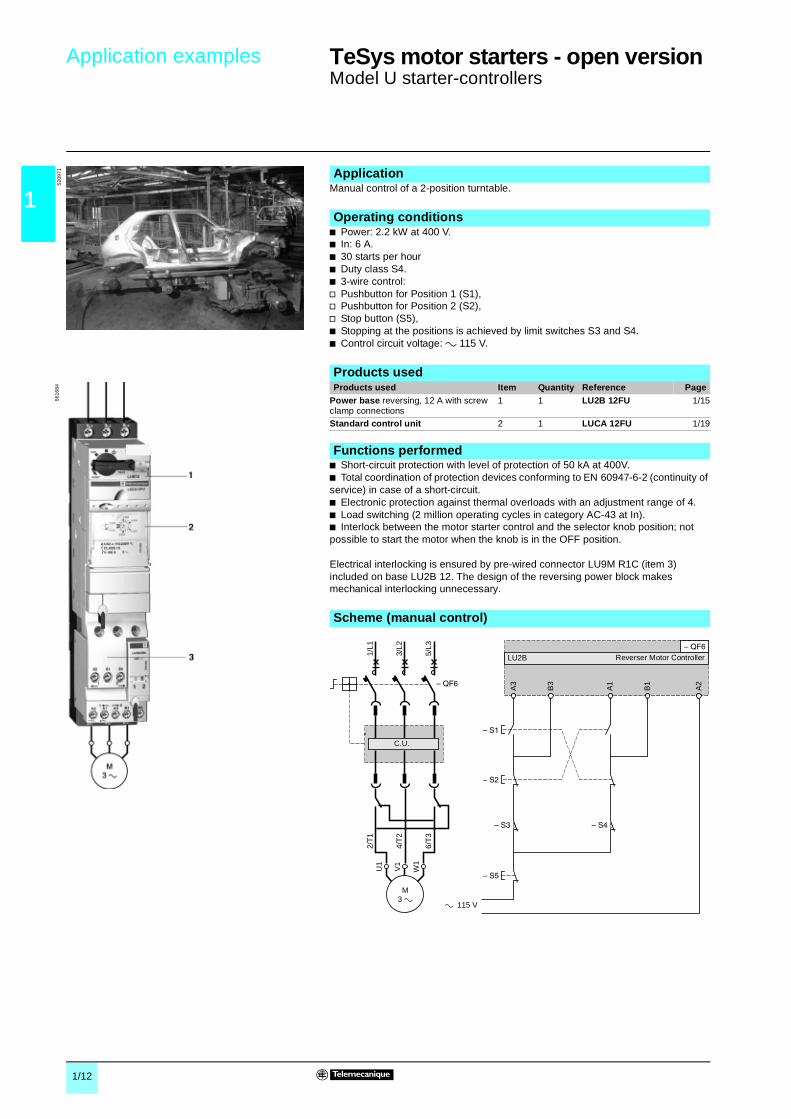
Manual control of a 2-position turntable.
b Power: 2.2 kW at 400 V.b In: 6 A.b 30 starts per hourb Duty class S4.b 3-wire control:v Pushbutton for Position 1 (S1),v Pushbutton for Position 2 (S2),v Stop button (S5),b Stopping at the positions is achieved by limit switches S3 and S4.b Control circuit voltage: a 115 V.
b Short-circuit protection with level of protection of 50 kA at 400V.b Total coordination of protection devices conforming to EN 60947-6-2 (continuity of service) in case of a short-circuit.b Electronic protection against thermal overloads with an adjustment range of 4.b Load switching (2 million operating cycles in category AC-43 at In).b Interlock between the motor starter control and the selector knob position; not possible to start the motor when the knob is in the OFF position.
Electrical interlocking is ensured by pre-wired connector LU9M R1C (item 3) included on base LU2B 12. The design of the reversing power block makes mechanical interlocking unnecessary.
Application
Operating conditions
Products used
5209
7156
1684 Products used Item Quantity Reference Page
Power base reversing, 12 A with screw clamp connections
1 1 LU2B 12FU 1/15
Standard control unit 2 1 LUCA 12FU 1/19
Functions performed
Scheme (manual control)
1/L1
3/L2
5/L3
2/T
1
4/T
2V
1
U1
W1
6/T
3
M3
A3
B3
A1
B1
A2
LU2B
115 V
C.U.
Reverser Motor Controller
1/13
1
Application examples 1 TeSys motor starters - open version 1
Model U controllers
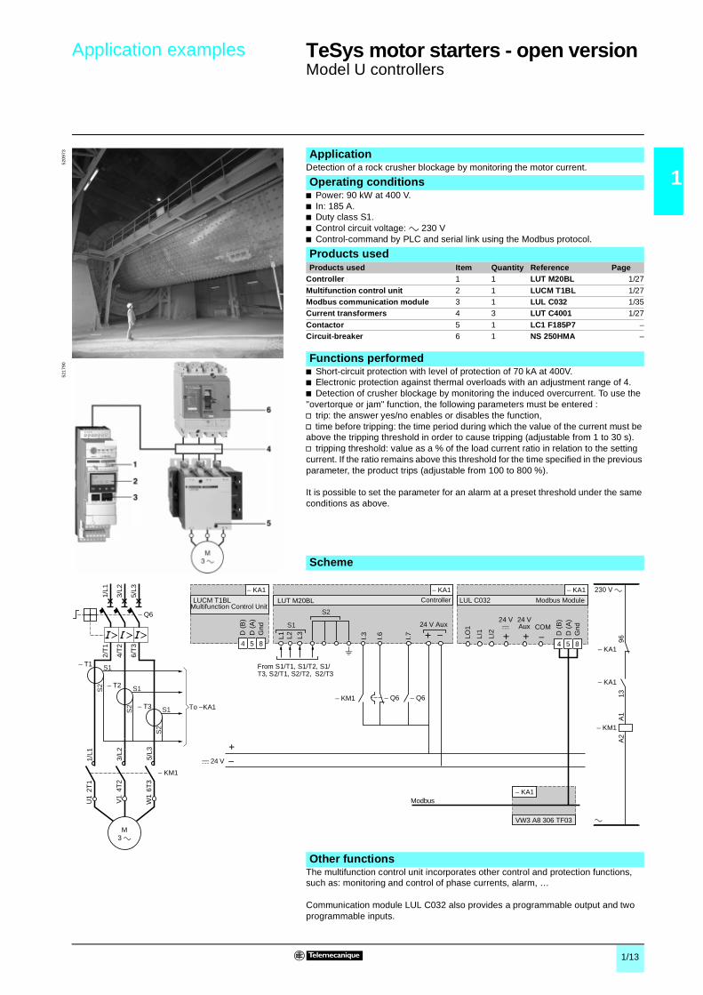
Detection of a rock crusher blockage by monitoring the motor current.
b Power: 90 kW at 400 V.b In: 185 A.b Duty class S1.b Control circuit voltage: a 230 Vb Control-command by PLC and serial link using the Modbus protocol.
b Short-circuit protection with level of protection of 70 kA at 400V.b Electronic protection against thermal overloads with an adjustment range of 4.b Detection of crusher blockage by monitoring the induced overcurrent. To use the "overtorque or jam" function, the following parameters must be entered :v trip: the answer yes/no enables or disables the function,v time before tripping: the time period during which the value of the current must be above the tripping threshold in order to cause tripping (adjustable from 1 to 30 s).v tripping threshold: value as a % of the load current ratio in relation to the setting current. If the ratio remains above this threshold for the time specified in the previous parameter, the product trips (adjustable from 100 to 800 %).
It is possible to set the parameter for an alarm at a preset threshold under the same conditions as above.
The multifunction control unit incorporates other control and protection functions, such as: monitoring and control of phase currents, alarm, …
Communication module LUL C032 also provides a programmable output and two programmable inputs.
Application
Operating conditions
Products used
5209
73
Products used Item Quantity Reference PageController 1 1 LUT M20BL 1/27
Multifunction control unit 2 1 LUCM T1BL 1/27Modbus communication module 3 1 LUL C032 1/35Current transformers 4 3 LUT C4001 1/27
Contactor 5 1 LC1 F185P7 –Circuit-breaker 6 1 NS 250HMA –
Functions performed
5217
90
Scheme
Other functions
230 V a
a
4 5 8
Modbus
4 5 8
VW3 A8 306 TF03
D (
B)
D (
A)
Gnd
+c 24 V
LO1
LI1
LI2 D (
B)
D (
A)
Gnd
I.3 I.6 I.7 9613
A1
A2
LUCM T1BL LUT M20BL
L1 L2 L3
LUL C032
2/T
1
4/T
2
6/T
3
1/L1
3/L2
5/L3
1/L1
2T1
3/L2
4T2
5/L3
6T3
U1
W1
V1
M3 a
– T1
– Q6
– Q6 – Q6
– KA1
– KM1
– KA1 – KA1
– KM1
– KA1
– KA1
– KA1
S1
S2 S1
S2 S1
S2
– T2
– T3
– KM1
S1
S2
Modbus ModuleController
From S1/T1, S1/T2, S1/T3, S2/T1, S2/T2, S2/T3
To –KA1
24 V Aux
Multifunction Control Unit
24 Vc
24 VAux COM
1/14
1
References TeSys motor starters - open version 0
Model U starter-controllersNon-reversing power bases
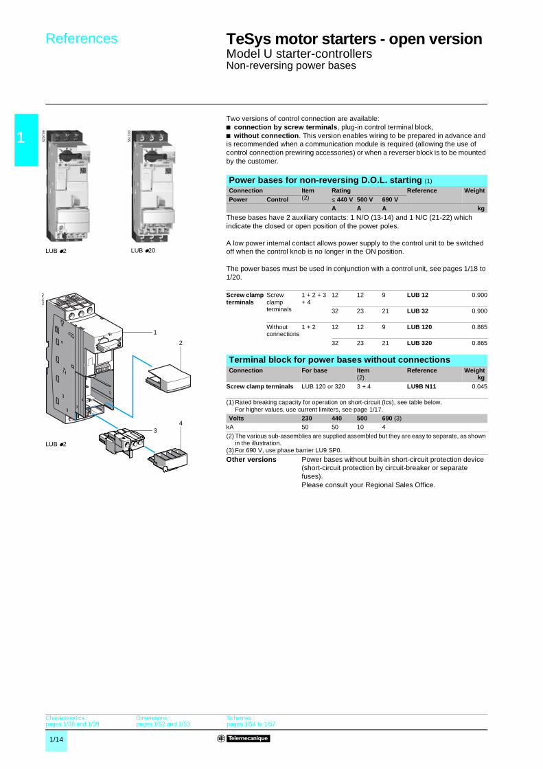
Two versions of control connection are available:b connection by screw terminals, plug-in control terminal block,b without connection. This version enables wiring to be prepared in advance and is recommended when a communication module is required (allowing the use of control connection prewiring accessories) or when a reverser block is to be mounted by the customer.
Power bases for non-reversing D.O.L. starting (1)
Connection Item(2)
Rating Reference WeightPower Control ≤ 440 V 500 V 690 V
A A A kg
These bases have 2 auxiliary contacts: 1 N/O (13-14) and 1 N/C (21-22) which indicate the closed or open position of the power poles.
A low power internal contact allows power supply to the control unit to be switched off when the control knob is no longer in the ON position.
The power bases must be used in conjunction with a control unit, see pages 1/18 to 1/20.
Screw clamp terminals
Screw clamp terminals
1 + 2 + 3+ 4
12 12 9 LUB 12 0.900
32 23 21 LUB 32 0.900
Without connections
1 + 2 12 12 9 LUB 120 0.865
32 23 21 LUB 320 0.865
Terminal block for power bases without connectionsConnection For base Item
(2)Reference Weight
kgScrew clamp terminals LUB 120 or 320 3 + 4 LU9B N11 0.045
(1) Rated breaking capacity for operation on short-circuit (Ics), see table below.For higher values, use current limiters, see page 1/17.
Volts 230 440 500 690 (3)kA 50 50 10 4
(2) The various sub-assemblies are supplied assembled but they are easy to separate, as shown in the illustration.
(3) For 690 V, use phase barrier LU9 SP0.
Other versions Power bases without built-in short-circuit protection device (short-circuit protection by circuit-breaker or separate fuses).Please consult your Regional Sales Office.
LUB p2
5207
39
LUB p20
5613
30
1
2
43
5207
40
Characteristics : pages 1/38 and 1/39
Dimensions : pages 1/52 and 1/53
Schemes :pages 1/54 to 1/57
LUB p2

1/15
1
References TeSys motor starters - open version 0
Model U starter-controllersReversing power bases
Two versions of control connection are available:b connection by screw terminals, plug-in control terminal block,b without connection. This version enables wiring to be prepared in advance and is recommended when a communication module is required, allowing the use of control connection pre-wiring accessories.
Power bases for reversing D.O.L. starting, pre-assembledConnection Item
(1)Rating Reference,
to be completed (2)
WeightPower Control ≤ 440 V 500 V 690 V
A A A kg
These bases have two N/O common point contacts (81-82-84) which indicate non-reversing and reversing operating status.Screw clamp terminals
Screw clamp terminals
1 + 2 + 3+ 4 + 5
12 12 9 LU2B 12pp 1.270
32 23 21 LU2B 32pp 1.270
Without connections
1 + 2 + 3 + 5
12 12 9 LU2B A0pp 1.270
32 23 21 LU2B B0pp 1.250
Power bases for reversing D.O.L. starting, for customer assemblyA reverser block should preferably be combined with a non-reversing power base without connections to create a reversing starter-controller.The built-in N/O (13-14) and N/C (21-22) contacts are used for electrical interlocking between the reverser block and the base; they are therefore no longer available as output contacts.The reverser block has two N/O common point contacts (81-82-84) which indicate non-reversing and reversing operating status.32 A reverser block Connection Item (1) Reference,
to be completed (2)
WeightkgPower Control
For mounting directly beneath the power base
Screw clamp terminals
Without connections
3 LU2M B0pp 0.400
For mounting separately from the base(screw or rail fixing)
Screw clamp terminals
Without connections
6 LU6M B0pp 0.425
AccessoriesDescription Item Application Reference Weight
kgControl terminal block
4 Reversing power base without connections LU2B A0pp or B0pp
LU9 M1 0.025
Reverser block LU2M B0pp for direct mounting beneath power base
LU9 M1 0.025
Reverser block LU6M B0pp for mounting separately from power base
LU9 M1 0.025
7 Reverser block LU6M B0pp for mounting separately from power base
LU9M R1 0.030
Control circuit pre-wiring componentsDescription Item Reference Weight
kgPre-wired connector (3) 5 LU9M R1C 0.035(1) The various sub-assemblies are supplied assembled but they are easy to separate, as shown
in the illustration.(2) Select the same control voltage as that of the control unit.
Standard control circuit voltages:
Volts 24 48…72 110…240c BL – –
a B – –c or a – ES (4) FU (5)(3) For control connection between a power base and a reverser block, for direct mounting.(4) c : 48…72 V, a : 48 V.(5) c : 110…220 V, a : 110...240 V.
Other versions Power bases without built-in short-circuit protection device (short-circuit protection by circuit-breaker or separate fuses). Please consult your Regional Sales Office.
LU2B p2
5612
70
4
3
5
1
2
LU2B p2
6
7
4
LU6M + LU9 M1 + LU9M R1
5207
4152
0826
Characteristics : pages 1/38 and 1/39
Dimensions : pages 1/52 and 1/53
Schemes :pages 1/54 to 1/57

1/16
1
Presentation,references 1
TeSys motor starters - open version 1
Model U starter-controllersAdd-on contact blocks and auxiliary contact modules
Contact statesProduct status Position of
control handle
Indication on front panel
N/O pole contact
N/C pole contact
N/O contact any fault
N/C contact any fault
N/O contact product ready
References of add-on contact blocks and auxiliary contact modulesTerminal referencing
– – – LUF N11 31-32
LUA1 C2097-98
LUA1 C11 95-96
LUA1 C2017-18
or – – – LUF N02 31-3241-42
LUA1 C200no terminal block
LUA1 C110no terminal block
LUA1 C200no terminal block
or – – LUF N20 33-3443-44
LU9B N1121-22
– – LUA1 C1117-18
or – – LUF N1143-44
– – – LUA1 C110no terminal block
or – – LU9B N11 13-14
– – – –
Off 0
Ready to operate 0
Start 1
Tripped on short-circuit I>>
Tripped on thermal overload
Manual reset mode 0
Automatic reset on thermal overload fault mode
0
Remote reset mode 0
N/O contact in closed position. N/O contact in open position
References
OFF
TRIP
TRIP
Add-on contact blocksSignalling and composition Connection Item Reference Weight
kg1 N/C fault signalling contact (95-96) and 1 N/O contact (17-18) indicating control handle in “ready” position
Screw clamp terminals
1 + 2 LUA1 C11 0.030
Without connections
1 LUA1 C110 0.012
1 N/O fault signallingcontact (97-98) and 1 N/O contact (17-18) indicating control handle in “ready” position
Screw clamp terminals
1 + 2 LUA1 C20 0.030
Without connections
1 LUA1 C200 0.012
Auxiliary contact modules for connection by screw clamp terminalsModule with 2 contacts indicating the status of the starter-controller power polesOperation: a or c 24…250 V, I th: 5 A Composition Item Reference Weight
kg
2 N/O contacts (33-34 and 43-44) 3 LUF N20 0.0501 N/C contact (31-32) and 1 N/O contact (43-44) 3 LUF N11 0.0502 N/C contacts (31-32 and 41-42) 3 LUF N02 0.050
AccessoriesDescription For use on Item Reference Weight
kgScrew clamp terminal blocks
LUA1 C110 2 LU9B C11 0.022LUA1 C200 2 LU9B C20 0.022
Blanking covers Location for auxiliary contact, communication or function module
4 LU9C 1 0.020
Location for add-on contact blocks 5 LU9C 2 0.010
3
4
2
1
5
5615
21
LUB + LUA1 + LUF N
Characteristics :page 1/40
Schemes :page 1/38

1/17
1
References 1 TeSys motor starters - open version 1
Model U starter-controllersPower connection pre-wired system, limiter blocks and accessories
(1) The maximum permissible peak current for power sockets AK5 PCpp is 6 kA. When used in association with power bases LUBpp, the prospective short-circuit current must not exceed 7 kA
(2) Supplied with limiter cartridge.(3) These devices make it possible to increase the breaking capacity of the power base.(4) Sold in lots of 100.(5) The fixing kit includes a shaft extension (maximum depth 508 mm).(6) The limiter must be mounted on an LUB or LU2B power base. The limiter can therefore not
be common to several motor starters.(7) To use the fixing kit with a D.O.L. reversing power base, only reverser block LU6 M must be
used.
Pre-wired system for power connections up to 63 ADescription Application Pitch
mmItem Sold in
lots ofUnitreference
Weightkg
Sets of 3-pole 63 A busbars
2 tap-offs 45 2 1 GV2 G245 0.03654 – 1 GV2 G254 0.038
3 tap-offs 45 – 1 GV2 G345 0.058
54 – 1 GV2 G354 0.0604 tap-offs 45 1 1 GV2 G445 0.077
54 – 1 GV2 G454 0.0855 tap-offs 54 – 1 GV2 G554 0.100
Protectiveend cover
For unused busbar outlets
– 4 5 GV1 G10 0.005
Terminal block for supply to one or more busbar sets
Connection from the top
– 3 1 GV1 G09 0.040
Pre-wired system for power connections up to 160 AThe busbar system can be screw-mounted onto any type of support.Set of 4-pole busbars: 3-phase + neutral or 3-phase + commonNumber of tap-offs at 18 mm intervals
Item Lengthmm
For mounting in enclosure widthmm
Reference Weight
kg18 5 452 800 AK5 JB144 0.900
Removable 3-phase power socketsNumber of points used on the busbar system
Thermal current
Item Cable lengths
Sold in lots of
Unit reference
Weight
kg2 16 6 200 6 AK5 PC13 (1) 0.040
32 6 250 6 AK5 PC33 (1) 0.045
1000 6 AK5 PC33L (1) 0.060
Limiter blocks and accessoriesApplication Item Breaking
capacity IqMounting Unit
referenceWeight
≤ 440 V 690 VkA kA kg
Limiter-disconnector (3) (6)
7 + 10 130 70 Direct on power base
LUA LB1 (2) 0.310
Current limiters (3)
8 100 35 Separate LA9 LB920 0.320
Limiter cartridge 10 130 70 Limiter-disconnector LUA LF1 0.135
Clip-in marker holder
– – – On power base, on reverser block, on parallel link splitter box
LAD 90 (4) 0.001
Phase barrierPhase barrier LU9 SP0 must be used:b To build a UL 508 type E certified starter (Self Protected Starter).Without the phase barrier, the starter-controller is certified UL 508.b If the starter-controller is to be used on an operational voltage of 690 V.Description Item Application Mounting Reference Weight
kgPhase barrier 9 LUB or LU2B 12 or 120
LUB or LU2B 32 or 320LUA LB1
Direct on terminalsL1, L2, L3
LU9 SP0 0.030
Door interlock mechanismsDescription Item Reference Weight
kgFixing kit (5) (7) 11 + 12 LU9 AP00 0.490
Door-mounted black handle/blue front plate, IP54 13 LU9 AP11 0.150Door-mounted red handle/yellow front plate, IP54 13 LU9 AP12 0.150
5 6
7
8
10
12
11
13
3
8 14 2
9
5614
2553
3845
5338
4453
3843
5615
24
Dimensions : pages 1/52 and 1/53
1/18
1
Selection 1 TeSys motor starters - open version 1
Model U starter-controllersControl units
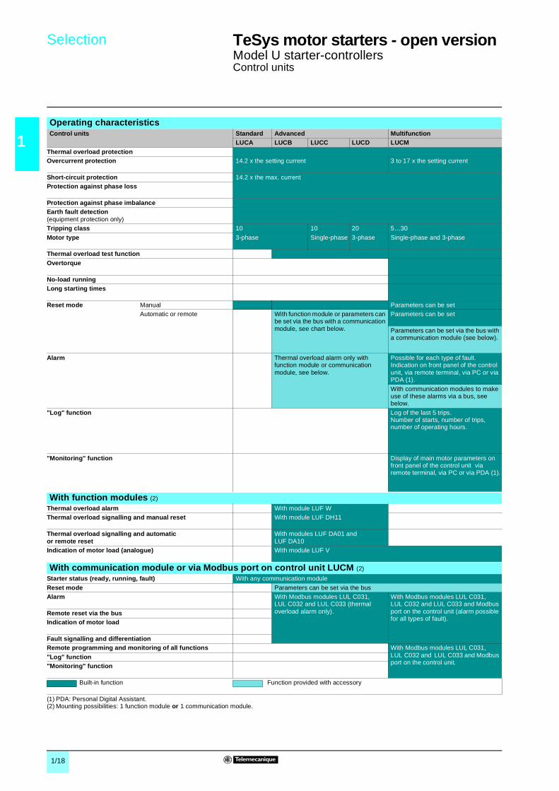
Operating characteristicsControl units Standard Advanced Multifunction
LUCA LUCB LUCC LUCD LUCMThermal overload protectionOvercurrent protection 14.2 x the setting current 3 to 17 x the setting current
Short-circuit protection 14.2 x the max. currentProtection against phase loss
Protection against phase imbalanceEarth fault detection(equipment protection only)Tripping class 10 10 20 5…30
Motor type 3-phase Single-phase 3-phase Single-phase and 3-phase
Thermal overload test functionOvertorque
No-load runningLong starting times
Reset mode Manual Parameters can be setAutomatic or remote With function module or parameters can
be set via the bus with a communication module, see chart below.
Parameters can be set
Parameters can be set via the bus with a communication module (see below).
Alarm
Thermal overload alarm only with function module or communication module, see below.
Possible for each type of fault. Indication on front panel of the control unit, via remote terminal, via PC or via PDA (1).
With communication modules to make use of these alarms via a bus, see below.
"Log" function Log of the last 5 trips. Number of starts, number of trips, number of operating hours.
"Monitoring" function Display of main motor parameters on front panel of the control unit via remote terminal, via PC or via PDA (1).
With function modules (2)
Thermal overload alarm With module LUF WThermal overload signalling and manual reset With module LUF DH11
Thermal overload signalling and automatic or remote reset
With modules LUF DA01 and LUF DA10
Indication of motor load (analogue) With module LUF V
With communication module or via Modbus port on control unit LUCM (2)
Starter status (ready, running, fault) With any communication module
Reset mode Parameters can be set via the busAlarm With Modbus modules LUL C031,
LUL C032 and LUL C033 (thermal overload alarm only).
With Modbus modules LUL C031, LUL C032 and LUL C033 and Modbus port on the control unit (alarm possible for all types of fault).
Remote reset via the busIndication of motor load
Fault signalling and differentiationRemote programming and monitoring of all functions With Modbus modules LUL C031,
LUL C032 and LUL C033 and Modbus port on the control unit.
"Log" function"Monitoring" function
Built-in function Function provided with accessory
(1) PDA: Personal Digital Assistant.(2) Mounting possibilities: 1 function module or 1 communication module.

1/19
1
References 1 TeSys motor starters - open version 1
Model U starter-controllersStandard and advanced control units
Description1 Extraction and locking handle2 Test button (on advanced control unit only)3 Ir adjustment dial4 Locking of settings by sealing the transparent cover5 Sealing of locking handle
Standard control unitsMaximum standard power ratings of 3-phase motors50/60 Hz
Setting range
Clip-in mounting on power baseRating
Referenceto be completed by adding the voltage code (1)
Weight
400/440 V 500 V 690 VkW kW kW A A kg
0.09 – – 0.15…0.6 12 and 32 LUCA X6pp 0.1350.25 – – 0.35…1.4 12 and 32 LUCA 1Xpp 0.135
1.5 2.2 3 1.25…5 12 and 32 LUCA 05pp 0.1355.5 5.5 9 3…12 12 and 32 LUCA 12pp 0.135
7.5 9 15 4.5…18 32 LUCA 18pp 0.13515 15 18.5 8…32 32 LUCA 32pp 0.135
Advanced control unitsPressing the Test button on the front panel simulates tripping on thermal overload.Class 10 for 3-phase motors
0.09 – – 0.15…0.6 12 and 32 LUCB X6pp 0.140
0.25 – – 0.35…1.4 12 and 32 LUCB 1Xpp 0.1401.5 2.2 3 1.25…5 12 and 32 LUCB 05pp 0.140
5.5 5.5 9 3…12 12 and 32 LUCB 12pp 0.1407.5 9 15 4.5…18 32 LUCB 18pp 0.14015 15 18.5 8…32 32 LUCB 32pp 0.140
Class 10 for single-phase motors– – – 0.15…0.6 12 and 32 LUCC X6pp 0.1400.09 – – 0.35…1.4 12 and 32 LUCC 1Xpp 0.1400.55 – – 1.25…5 12 and 32 LUCC 05pp 0.140
2.2 – – 3…12 12 and 32 LUCC 12pp 0.1404 – – 4.5…18 32 LUCC 18pp 0.140
7.5 – – 8…32 32 LUCC 32pp 0.140
Class 20 for 3-phase motors0.09 – – 0.15…0.6 12 and 32 LUCD X6pp 0.1400.25 – – 0.35…1.4 12 and 32 LUCD 1Xpp 0.140
1.5 2.2 3 1.25…5 12 and 32 LUCD 05pp 0.1405.5 5.5 9 3…12 12 and 32 LUCD 12pp 0.140
7.5 9 15 4.5…18 32 LUCD 18pp 0.14015 15 18.5 8…32 32 LUCD 32pp 0.140
(1) Standard control circuit voltages:Volts 24 48…72 110…240c BL (2), (3) – –a B – –c or a – ES (4) FU (5)
(2) Voltage code to be used for a starter-controller with communication module.(3) d.c. voltage with maximum ripple of ± 10 %.(4) c : 48…72 V, a : 48 V.(5) c : 110…220 V, a : 110...240 V.
5
1
2
34
5306
55
LUCA ppppLUCB pppp
LUB p2 + LUCA pppp
5207
35
LUB p2 + LUCB pppp
5207
36
Characteristics : pages 1/38 and 1/41
Schemes :pages 1/54 to 1/57

1/20
1
References 1 TeSys motor starters - open version 1
Model U starter-controllersMultifunction control units
Description1 Extraction and locking handle2 Built-in display window (2 lines, 12 characters)3 4-button keypad4 c 24 V auxiliary power supply5 Modbus RS485 communication port. Connection by RJ45 connector.6 Sealing of locking handleThe display window 2 and keypad 3 allow:b in configuration mode: local configuration of protection functions and alarms,b in run mode: display of parameter values and events.The Modbus communication port 5 is used to connect:b an operator terminal,b a PC,b a Personal Digital Assistant (PDA).
Multifunction control unitsParameter entry, monitoring of parameter values and consultation of logs are carried out:b either on the front panel, using the built-in display window/keypad,b or via an operator terminal,b or via a PC or a PDA with PowerSuite software,b or remotely, via a Modbus communication bus.Programming of the product via the keypad requires a c 24 V auxiliary power supply.Maximum standard power ratings of 3-phase motors 50/60 Hz
Setting range
Clip-in mounting on power baseRating
Reference (1)
Weight
400/415 V 500 V 690 VkW kW kW A A kg
0.09 – – 0.15…0.6 12 and 32 LUCM X6BL 0.175
0.25 – – 0.35…1.4 12 and 32 LUCM 1XBL 0.1751.5 2.2 3 1.25…5 12 and 32 LUCM 05BL 0.175
5.5 5.5 9 3…12 12 and 32 LUCM 12BL 0.1757.5 9 15 4.5…18 32 LUCM 18BL 0.175
15 15 18.5 8…32 32 LUCM 32BL 0.175
TeSys model U user's manual (2)
Application Language Reference Weightkg
On CD-Rom Multi-language (3) LU9 CD1 0.022
Operator terminalThis compact Magelis terminal enables the parameters of multifunction control unit LUCM to be read and modified. It is supplied pre-configured to provide dialogue with 8 model U starter-controllers (Modbus protocol, application pages and alarm pages loaded). Starter-controller alarm and fault management takes priority.Language Display window Supply voltage Reference Weight
kgMulti-language (3) 4 lines of
20 charactersc 24 V XBT NU400 0.150
Connecting cable (4)
Function Length Type Reference Weightkg
Connects terminal XBT NU400 to a multifunction control unit.
2.5 m SUB-D 25-way female - RJ45
XBT Z938 0.200
(1) Input voltage c 24 V with maximum ripple of ± 10 %.(2) The CD-Rom contains user's manuals for the AS-Interface and Modbus communication
modules, multifunction control units and gateway modules, as well as the gateway programming software.
(3) English, French, German, Italian, Spanish(4) If a terminal is used with several control units, this cable can be connected to a Modbus hub
or to T-junctions (see page 1/35).
6
1
2
3
5
4
5306
56
LUCM ppBL
LUB p2 + LUCM ppBL
5207
37
XBT NU400
5213
35
Characteristics : pages 1/38 and 1/41
Schemes :pages 1/54 to 1/57

1/21
1
References 1 TeSys motor starters - open version 1
Model U starter-controllersFunction modules
Function modulesOutput Item Application Reference Weight
kg
Thermal overload signalling and manual resetModule LUF DH11 makes it possible to differentiate thermal overload and short-circuit faults. (The short-circuit fault can then be signalled via add-on contact blocks LUA1 C). The module includes two contacts for thermal overload signalling, as well as an LED on the front panel. To reset the motor starter, the operator must use the rotary knob on the power base. The module can only be used with an advanced control unit and requires an a/c 24…240 V external powr supply.
1 N/O + 1 N/C 3 a or c 24…250 V LUF DH11 0.060
Thermal overload signalling and automatic or remote resetThese modules make it possible to differentiate thermal overload and short-circuit faults. (The short-circuit fault can then be signalled via add-on contact blocks LUA1 C). The modules include one contact for thermal overload signalling, as well as an LED on the front panel. A second contact (terminals Z1-Z2) must be wired in series with terminal A1 of the motor starter. In the event of a thermal overload fault, this wiring allows motor control to be switched off. The rotary knob on the power base will then stay in the "ready position" .Resetting of the motor starter is automatic after the required motor cooling time if terminals X1-X2 are linked by a strap, or remote by pulsed closing of a volt-free contact connected to terminals X1-X2.
These modules can only be used with an advanced control unit and require an a/c 24…240 V external powr supply.
Note : Terminals X1-X2 are not isolated from the signalling module power supply.For remote resetting, use a volt-free contact specifically for each module to be reset.
1 N/C 4 a or c 24…250 V LUF DA01 0.0551 NO 4 a or c 24…250 V LUF DA10 0.055
Thermal overload alarmThrough load shedding, this module makes it possible to avoid stoppages in operation due to overload tripping.Imminent thermal overload tripping is displayed as soon as the thermal state exceeds the threshold of 105 % (hysteresis = 5 %).Signalling is possible via an LED on the front panel of the module and externally by an N/O relay output.It can only be used with an advanced control unit, from which it takes its power.
1 N/O 1 a or c 24…250 V LUF W10 0.055
Indication of motor loadThis module provides a signal which is representative of the motor load status (I average/Ir).b I average = average value of the rms currents in the 3 phases,b Ir = value of the setting current.The value of the signal (4-20 mA) corresponds to a load status of 0 to 200 % (0 to 300 % for a single-phase load).It can be used with an advanced or multifunction control unit.Module LUF V2 requires a c 24 V external power supply.
4 - 20 mA 2 – LUF V2 0.050
2
3
4
1
12
3
100
200%
20 mA4 12 mA
LUB p2 + LUCB pppp + LUFW 10 or LUF Vp
5338
4651
0445
1 2.2 kW2 4 kW3 7.5 kW
Characteristics : pages 1/38 and 1/43
Schemes :pages 1/54 to 1/57

1/22
1
Presentation,functions 1
PowerSuite software workshop 1
The PowerSuite software workshop for PC is a user-friendly tool designed for setting up control devices for the following Telemecanique brand motors:b TeSys model U controller-startersb Altistart soft start/soft stop unitsb Altivar variable speed drives.It includes various functions designed for setup phases such as:b Preparing configurationsb Start-upb Maintenance.In order to simplify the start-up and maintenance phases, the PowerSuite software workshop can use the Bluetooth® wireless link.
The PowerSuite software workshop can be used on its own to generate the device configuration. It can be saved, printed and exported to office automation software.
The PowerSuite software workshop can also be used to convert:b An Altivar 28 drive configuration to an Altivar 31 drive configurationb An Altivar 38 drive configuration to an Altivar 61 drive configurationb An Altivar 58 or Altivar 58F drive configuration to an Altivar 71 drive configuration.
When the PC is connected to the device, the PowerSuite software workshop can be used to:b Transfer the generated configurationb Adjustb Monitor. This option has been enhanced with new functions such as:v The oscilloscopev The high speed oscilloscope (minimum time base: 2 ms)v Displaying communication parametersb Controlb Save the final configuration.
In order to simplify maintenance operations, the PowerSuite software workshop can be used to:b Compare the configuration of a device currently being used with a saved configurationb Manage the user’s installed base of equipment, in particular:v Organize the installed base into folders (electrical equipment, machinery, workshops, etc.)v Store maintenance messagesv Simplify Ethernet connection by storing the IP address.
The PowerSuite software workshop can be used to:b Present the device parameters arranged by function in the form of illustrated views of diagrams or simple tablesb Customize the parameter namesb Create:v A user menu (choice of particular parameters)v Monitoring control panels with graphic elements (cursors, gauges)b Perform sort operations on the parametersb Display text in five languages (English, French, German, Italian and Spanish). The language changes immediately and there is no need to restart the program.
It also has online contextual help:b On the PowerSuite toolb On the device functions by direct access to the user manuals.
(1) Some functions are not available for all devices. See the table of function availability, page 1/23.
Presentation
Functions (1) Preparing configurations
5345
13
PowerSuite screen on PCInstalled base management
5331
81
PowerSuite screen on PCView of PI regulator function parameters
5331
82
PowerSuite screen on PCMonitoring control panel (cursor, gauge)
Start-up
Maintenance
User interface
References:page 1/24
1/23
1
Functions (continued) 1 PowerSuite software workshop 1
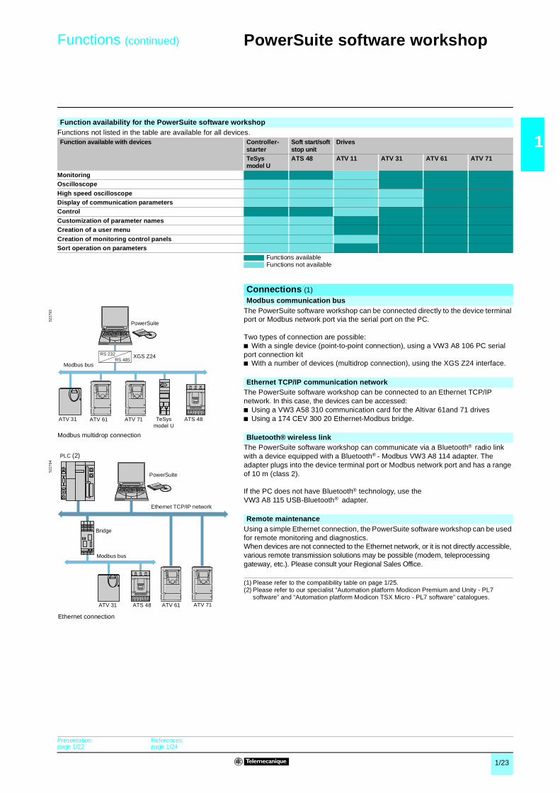
Function availability for the PowerSuite software workshopFunctions not listed in the table are available for all devices.Function available with devices Controller-
starterSoft start/soft stop unit
Drives
TeSys model U
ATS 48 ATV 11 ATV 31 ATV 61 ATV 71
MonitoringOscilloscopeHigh speed oscilloscopeDisplay of communication parametersControlCustomization of parameter namesCreation of a user menuCreation of monitoring control panelsSort operation on parameters
Functions available Functions not available
Connections (1)
Modbus communication bus The PowerSuite software workshop can be connected directly to the device terminal port or Modbus network port via the serial port on the PC.
Two types of connection are possible:b With a single device (point-to-point connection), using a VW3 A8 106 PC serial port connection kit b With a number of devices (multidrop connection), using the XGS Z24 interface.
Ethernet TCP/IP communication networkThe PowerSuite software workshop can be connected to an Ethernet TCP/IP network. In this case, the devices can be accessed:b Using a VW3 A58 310 communication card for the Altivar 61and 71 drivesb Using a 174 CEV 300 20 Ethernet-Modbus bridge.
Bluetooth® wireless link
The PowerSuite software workshop can communicate via a Bluetooth® radio link with a device equipped with a Bluetooth® - Modbus VW3 A8 114 adapter. The adapter plugs into the device terminal port or Modbus network port and has a range of 10 m (class 2).
If the PC does not have Bluetooth® technology, use theVW3 A8 115 USB-Bluetooth® adapter.
Remote maintenanceUsing a simple Ethernet connection, the PowerSuite software workshop can be used for remote monitoring and diagnostics.When devices are not connected to the Ethernet network, or it is not directly accessible, various remote transmission solutions may be possible (modem, teleprocessing gateway, etc.). Please consult your Regional Sales Office.
(1) Please refer to the compatibility table on page 1/25.(2) Please refer to our specialist “Automation platform Modicon Premium and Unity - PL7
software” and “Automation platform Modicon TSX Micro - PL7 software” catalogues.
RS 232RS 485
5227
93
Modbus multidrop connection
Modbus bus
ATV 31 ATV 61 ATV 71 TeSys model U
PowerSuite
ATS 48
XGS Z24
5227
94
Ethernet connection
Bridge
PLC (2)
Ethernet TCP/IP network
ATV 31 ATS 48 ATV 61 ATV 71
Modbus bus
PowerSuite
Presentation:page 1/22
References:page 1/24

1/24
1
References 1 PowerSuite software workshop 1
PowerSuite software workshopDescription Composition Reference Weight
kgPowerSuite CD-ROM b 1 program for PC in English, French, German, Italian
and Spanish b Variable speed drive and starter technical manuals.
VW3 A8 104 0.100
PowerSuite update CD-ROM (1)
b 1 program for PC in English, French, German, Italian and Spanish
b Variable speed drive and starter technical manuals.
VW3 A8 105 0.100
Connection kit for PC serial portfor point-to-point Modbus connection
b 1 x 3 m cable with 2 RJ45 connectorsb 1 RS 232/RS 485 converter with one 9-way female SUB-D
connector and 1 RJ45 connectorb 1 converter for the ATV 11 drive, with one 4-way male
connector and one RJ45 connectorb 1 RJ45/9-way male SUB-D adapter for connecting
ATV 38/58/58F drivesb 1 RJ45/9-way female SUB-D adapter for connecting
ATV 68 drives.
VW3 A8 106 0.350
RS 232-RS 485 interfacefor multidrop Modbus connection
1 multidrop Modbus converter for connection to screw terminals. Requires a 24 Vc (20...30 V), 20 mA power supply (3).
XGS Z24 0.105
Modbus-Bluetooth®
adapter (2)b 1 Bluetooth® adapter (10 m range, class 2)
with 1 RJ45 connectorb 1 x 0.1 m cable with 2 RJ45 connectors
for PowerSuiteb 1 x 0.1 m cable with 1 RJ45 connector and 1 mini DIN
connector for TwidoSoftb 1 RJ45/9-way male SUB-D adapter for connecting
ATV 38/58/58F drives.
VW3 A8 114 0.155
USB-Bluetooth® adapter for PC
This adapter is required for a PC which is not equippedwith Bluetooth® technology. It is connected to a USB port on the PC.Range of 10 m (class 2).
VW3 A8 115 0.290
(1) Updates a version u V1.50 with the latest available version. For versions < V1.50, you should order the PowerSuite CD-ROM, VW3 A8 104.
(2) Can also be used to communicate between a Twido PLC and the TwidoSoft software workshop.(3) Please consult our “Interfaces, I/O splitter boxes and power supplies” catalogue.
VW3 A8 104
5228
38
VW3 A8 114
5331
88
Presentation:page 1/22
Functions:pages 1/22 and 1/23
1/25
1
Compatibility 1 PowerSuite software workshop 1
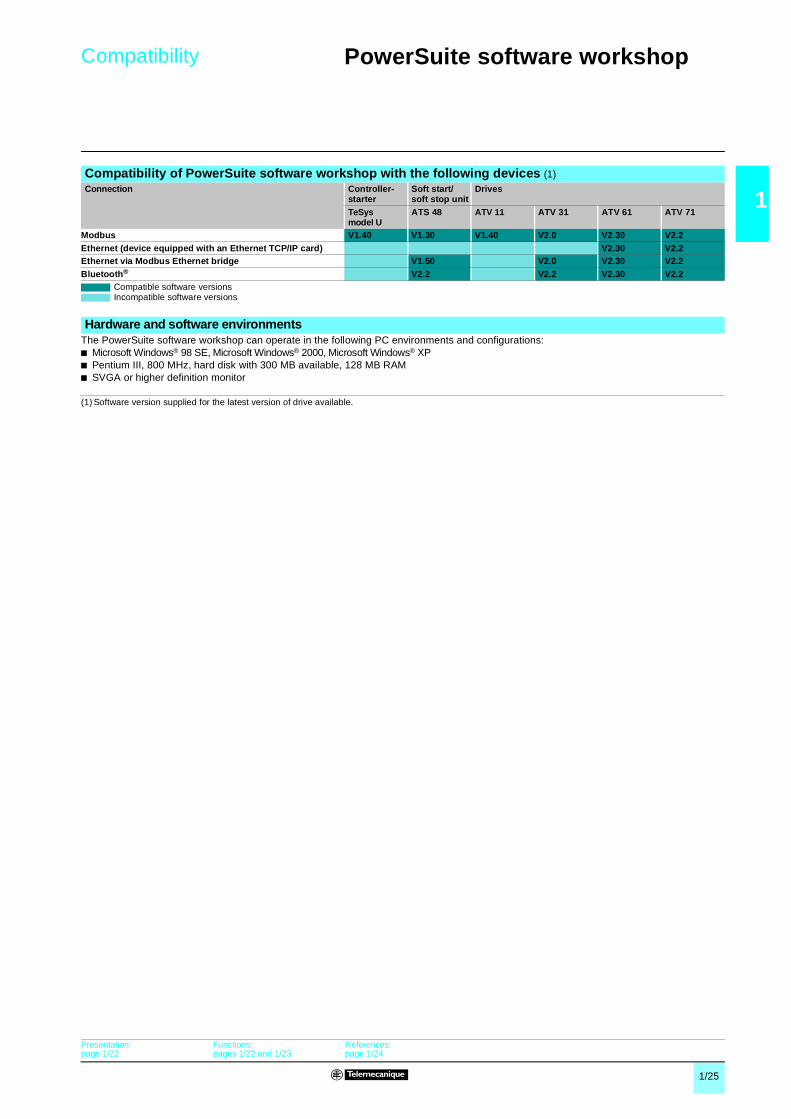
Compatibility of PowerSuite software workshop with the following devices (1)Connection Controller-
starterSoft start/soft stop unit
Drives
TeSys model U
ATS 48 ATV 11 ATV 31 ATV 61 ATV 71
Modbus V1.40 V1.30 V1.40 V2.0 V2.30 V2.2Ethernet (device equipped with an Ethernet TCP/IP card) V2.30 V2.2Ethernet via Modbus Ethernet bridge V1.50 V2.0 V2.30 V2.2Bluetooth® V2.2 V2.2 V2.30 V2.2
Compatible software versionsIncompatible software versions
Hardware and software environmentsThe PowerSuite software workshop can operate in the following PC environments and configurations:b Microsoft Windows® 98 SE, Microsoft Windows® 2000, Microsoft Windows® XPb Pentium III, 800 MHz, hard disk with 300 MB available, 128 MB RAMb SVGA or higher definition monitor
(1) Software version supplied for the latest version of drive available.
Presentation:page 1/22
Functions:pages 1/22 and 1/23
References:page 1/24

1/26
1
Presentation,combinations 1
TeSys control components 1
Model U controllers
PresentationAbove 32 A, the model U controller provides a motor starter management solution identical to that provided by TeSys model U starter-controllers.
Used in conjunction with a short-circuit protection device and a contactor, it provides a motor starter whose functions are the same as those of a TeSys model U starter-controller and, in particular, provides the following functions: overload protection, motor starter control and application monitoring.
CompositionIt consists of a control unit whose adjustment range is compatible with the secondary of current transformers, plus a control base which also allows fitment of a function module or a communication module.
It requires a c 24 V external power supply.
The secondaries of current transformers, the c 24 V power supply, the 10 inputs and the 5 outputs are connected by screw terminal block.
Combinations providing type 2 coordinationWith circuit-breakerStandard power ratings of 3-phase motors 50-60 Hzin category AC-3 400/415 V
Circuit-breaker (1) Contactor Model U controller Current transformers
PkW
IeA
Reference RatingA
Irm (2)A
Reference (3) Reference Reference
18,5 35 NS80HMA 50 500 LC1 D40 LUTM + LUCp 3 x LUT C050122 42 NS80HMA 50 650 LC1 D50 LUTM + LUCp 3 x LUT C100130 57 NS80HMA 80 880 LC1 D65 LUTM + LUCp 3 x LUT C100137 69 NS80HMA 80 1040 LC1 D80 LUTM + LUCp 3 x LUT C100145 81 NS100HMA 100 1300 LC1 D95 LUTM + LUCp 3 x LUT C100155 100 NS160HMA 150 1350 LC1 D115 LUTM + LUCp 3 x LUT C200175 135 NS160HMA 150 1800 LC1 D150 LUTM + LUCp 3 x LUT C200190 165 NS250HMA 220 2200 LC1 F185 LUTM + LUCp 3 x LUT C2001110 200 NS250HMA 220 2640 LC1 F225 LUTM + LUCp 3 x LUT C4001132 240 NS400HMA 320 3200 LC1 F265 LUTM + LUCp 3 x LUT C4001160 285 NS400HMA 320 4160 LC1 F330 LUTM + LUCp 3 x LUT C4001200 352 NS630HMA 500 5000 LC1 F400 LUTM + LUCp 3 x LUT C4001220 388 NS630HMA 500 5500 LC1 F400 LUTM + LUCp 3 x LUT C4001250 437 NS630HMA 500 6000 LC1 F500 LUTM + LUCp 3 x LUT C8001
With fusesStandard power ratings of 3-phase motors 50-60 Hz in category AC-3 400/415 V
Switch disconnector-fuse
aM fuses Contactor Model U controller Current transformers
PkW
IeA
Reference Size RatingA
Reference (3) Reference Reference
18,5 35 GS1 F 14 x 51 40 LC1 D40 LUTM + LUCp 3 x LUT C050122 42 GS1 J 22 x 58 50 LC1 D50 LUTM + LUCp 3 x LUT C100130 57 GS1 J 22 x 58 80 LC1 D65 LUTM + LUCp 3 x LUT C100137 69 GS1 J 22 x 58 100 LC1 D80 LUTM + LUCp 3 x LUT C100145 81 GS1 J 22 x 58 100 LC1 D95 LUTM + LUCp 3 x LUT C100155 100 GS1 L T0 125 LC1 D115 LUTM + LUCp 3 x LUT C200175 135 GS1 L T0 160 LC1 D150 LUTM + LUCp 3 x LUT C200190 165 GS1 N T1 200 LC1 F185 LUTM + LUCp 3 x LUT C2001110 200 GS1 N T1 250 LC1 F225 LUTM + LUCp 3 x LUT C4001132 240 GS1 QQ T2 315 LC1 F265 LUTM + LUCp 3 x LUT C4001160 285 GS1 QQ T2 400 LC1 F330 LUTM + LUCp 3 x LUT C4001200 352 GS1 S T3 500 LC1 F400 LUTM + LUCp 3 x LUT C4001220 388 GS1 S T3 500 LC1 F400 LUTM + LUCp 3 x LUT C4001250 437 GS1 S T3 500 LC1 F500 LUTM + LUCp 3 x LUT C8001315 555 GS1 S T3 630 LC1 F630 LUTM + LUCp 3 x LUT C8001(1) Product marketed under the Merlin Gerin brand.(2) Irm: setting current of the magnetic trip(3) For reversing operation, replace the prefix LC1 with LC2.
References :page 1/27
Characteristics : pages 1/44 and 1/45
Dimensions, mounting : page 1/28
Schemes : page 1/29

1/27
1
References 1 TeSys control components 1
Model U controllers
ReferencesControl bases (control circuit voltage c 24 V)Connection For use
with contactorReference Weight
kgCurrent transformers Control
Screw Screw LC1 Dpp LUT M10BL 0.800
LC1 Fppp LUT M20BL 0.800
Control unitsDescription Class For motor
typeSetting range Reference Weight
kgAdvanced 10 3-phase 0.35…1.05 LUCB T1BL 0.140
20 3-phase 0.35…1.05 LUCD T1BL 0.140
Multifunction 5 to 30 3-phase 0.35…1.05 LUCM T1BL 0.175
Current transformersOperating current Reference Weight
kgPrimary Secondary30 1 LUT C0301 0.200
50 1 LUT C0501 0.200
100 1 LUT C1001 0.200
200 1 LUT C2001 0.200
400 1 LUT C4001 0.430
800 1 LUT C8001 0.600
Function modules and communication modulesThe TeSys model U controller is compatible with the modules listed below.b Thermal overload alarm module LUF W10 (1), see page 1/21.b Motor load indication module LUF V2, see page 1/21.b Modbus communication modules LUL C032 and LUL C033, see page 1/34.
(1) Module LUF W10 is only compatible with control units LUCB T1BL and LUCD T1BL.
5320
83
LUT M + LUCM T1BL + LUTC pp
Presentation : page 1/26
Characteristics : pages 1/44 and 1/45
Dimensions, mounting :page 1/28
Schemes : page 1/29

1/28
1
Dimensions,mounting 1
TeSys control components 1
Model U controllers
Dimensions
Mounting
114 45
163
173
114 30Ø4
171
73
Presentation : page 1/26
Characteristics : pages 1/44 and 1/45
References :page 1/27
Schemes : page 1/29

1/29
1
Schemes 1 TeSys control components 1
Model U controllers
SchemesReversing controller LUT M
3-wire control, pulsed start with maintaining contact
Control for Modbus communication modules LUL C032 and LUL C033
(1) The contacts are represented with controller powered up and not in a fault condition.
L1 L2 L3
LUTM
13/N
O
23/N
O
95 96/N
O
97/N
C
LUTM
98 05 06/N
C
I.1 I.2 I.3 I.4
+
LUTM
I.5 I.6 I.7 I.8 I.9 I.10
LUTM
S1
S2
(1)(1)
24 V Aux.
I.9 I.10
I.1 I.2 I.3 I.4 I.5 R
ST
I.6 S
F
I.7 S
R
I.8 + + –
13
– KM1 – KM2
23 95 96 97 98 05 06
24 V c24…250 V a
– KM1AV – KM2 – Q1AR 24 V c
24 V cChannel 1 Channel 2
Any fault
Control unit fault
External fault
Trip
Stop
Reset
I.9 I.10
I.1 I.2 I.3 I.4 I.5 R
ST
I.6 S
F
I.7 S
R
I.8 + + –
13
– KM1 – KM2
23 95 96 97 98 05 06
24 V c24…250 V a
– KM1 – KM2
– Q1– Q1 24 V c
24 V c
– KM1 – KM2 AU
CO
M
OA
1
OA
3
LO1
LI1
LI2
AU
Channel 1 Channel 2
Any fault
Control unit fault
“Local”/“remote”
Trip
Stop
Reset
Man 1 Man 2
Any fault
Free Free On
Modbus network port
Communication module
“Local”/“remote”
Présentation : page 1/26
Characteristics : pages 1/44 and 1/45
References :page 1/27
Dimensions, mounting : page 1/28
1/30
1
References 1 TeSys motor starters - open version 1
Model U starter-controllersParallel wiring module and pre-wired coil connection components
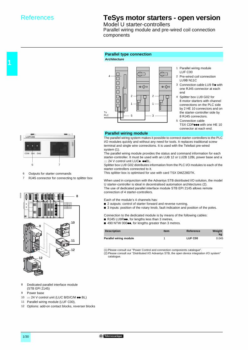
The parallel wiring system makes it possible to connect starter-controllers to the PLC I/O modules quickly and without any need for tools. It replaces traditional screw terminal and single wire connections. It is used with the Telefast pre-wired system (1).The parallel wiring module provides the status and command information for each starter-controller. It must be used with an LUB 12 or LU2B 12BL power base and a c 24 V control unit LUCp ppBL.Splitter box LU9 G02 distributes information from the PLC I/O modules to each of the starter-controllers connected to it.This splitter box is optimised for use with card TSX DMZ28DTK.
When used in conjunction with the Advantys STB distributed I/O solution, the model U starter-controller is ideal in decentralised automation architectures (2). The use of dedicated parallel interface module STB EPI 2145 allows remote connection of 4 starter-controllers.
Each of the module’s 4 channels has:b 2 outputs: control of starter forward and reverse running,b 3 inputs: position of the rotary knob, fault indication and position of the poles.
Connection to the dedicated module is by means of the following cables: b RJ45 LU9Rpp, for lengths less than 3 metres,b 490 NTW 000pp, for lengths greater than 3 metres.
Parallel type connectionArchitecture
1 Parallel wiring module LUF C00
2 Pre-wired coil connection LU9B N11C
3 Connection cable LU9 Rp with one RJ45 connector at each end
4 Splitter box LU9 G02 for 8 motor starters with channel connections on the PLC side by 2 HE 10 connectors and on the starter-controller side by 8 RJ45 connectors.
5 Connection cable TSX CDPppp with one HE 10 connector at each end.
Parallel wiring module
1
35
2
1
2
4
ToPLC
Description Item Reference Weightkg
Parallel wiring module 1 LUF C00 0.045
12
910
11
12
8
5318
10
8 Dedicated parallel interface module (STB EPI 2145)
9 Power base10 c 24 V control unit (LUC B/D/C/M pp BL)11 Parallel wiring module (LUF C00),12 Options: add-on contact blocks, reverser blocks
6 Outputs for starter commands7 RJ45 connector for connecting to splitter box
6 7
5208
36
(1) Please consult our "Power Control and connection components catalogue”.(2) Please consult our "Distributed I/O Advantys STB, the open device integration I/O system"
catalogue.

1/31
1
References 1 TeSys motor starters - open version 1
Model U starter-controllersParallel wiring module and pre-wired coil connection components
Pre-wired components simplify wiring and reduce wiring errors.
By pre-wired connector or wire link.
b Pre-wired connector: pre-wired coil connectionThe use of a power base without pre-wired connections is recommended.
b Wire link:Allows insertion, for example, of an emergency stop control or a voltage interface.This type of connection must be used for a reversing starter-controller assembled using an LU6M reverser block for separate mounting. When reverser block LU6M and the power base are mounted side-by-side, a pre-wired connector LU9M RC may be used.
No tools are required to connect the parallel wiring module to the PLC. Connection is via a splitter box which allows up to 8 starter-controllers to be connected; a maximum of 4 reversing starters per splitter box is allowed.The splitter box requires a c 24 V power supply.
(1) Allows "run" and "fault" status of each starter-controller to be fed back to the PLC and transmits commands.
1
2
5208
13
LUB + LUF C00 + LU9B
1
8
5614
20
LU2B + LUF C00 + LU9M
Connection of communication module output terminals to the coil terminals
Description For use withpower base
Item Reference Weightkg
Pre-wired coil connection
LUB pp 2 LU9B N11C 0.045
LU2B pp 8 LU9M RC 0.030
Connection of parallel wiring module to the PLC
Splitter blockConnectors Item Reference Weight
kgPLC side(16I/12O)
Starter-controller side
2 x HE 10 20-way
8 x RJ45 4 LU9 G02 (1) 0.260
Connection cables to the splitter boxConnectors Item Length
mReference Weight
kg2 x RJ45 connectors 3 0.3 LU9 R03 0.045
1 LU9 R10 0.0653 LU9 R30 0.125
Connection cables from splitter box to PLCType of connection Gauge C.s.a. Length Reference WeightPLC side Splitter
box sideAWG mm2 m kg
HE 10 20-way HE 10 20-way
22 0.324 0.5 TSX CDP 053 0.0851 TSX CDP 103 0.150
2 TSX CDP 203 0.2803 TSX CDP 303 0.410
5 TSX CDP 503 0.670
28 0.080 1 ABF H20 H100 0.080
2 ABF H20 H200 0.1403 ABF H20 H300 0.210
Bare wires HE 10 20-way
22 0.324 3 TSX CDP 301 0.4005 TSX CDP 501 0.660
Characteristics : pages 1/38 and 1/43
Schemes :pages 1/54 to 1/57

1/32
1
References 1 AS-Interface cabling system 1
Dedicated componentsTeSys Model U starter-controllers
The AS-Interface communication modules make it easy to connect starter-controllers to the AS-Interface cabling system, and therefore allow remote control and command of these starter-controllers.
Module ASILUF C51 incorporates wide mounting rail.
The various operating states of the modules (AS-Interface voltage present, communication fault, addressing fault,…) are indicated on the front panel by 2 LEDs (green 4 and red 5).
Operation of the modules is continuously monitored by auto-testing, in a way that is totally transparent to the user.
The incorporation of AS-Interface V.2.1 functions allows diagnostics to be performed on the modules, either remotely via the line or locally via the ASI TERV2 addressing terminal.
The communication modules must be connected to a c 24 V auxiliary supply and must be used in conjunction with a c 24 V control unit, LUCp ppBL.The product is supplied with a yellow connector 6 for connection to the AS-Interface system, a black connector 7 for connection to the c 24 V auxiliary supply and a black connector 8 for connection of the outputs.
Series type connectionArchitecture
1 Communication modules ASI LUF C5 or ASI LUF C51
2 Tap-off XZ CG01423 Pre-wired coil connection LU9B N11C
Information transmitted by the AS-Interface system
c 24 V
AS-Interface
13
2
AS-Interface profiles 7.D.F.0 profile and 7.A.7.E profileData bits (command) Bit value = 0 = 1
Command D0 (O) Stop forward Forward runningCommand D1 (O) Stop reverse Reverse running
Command D2 (O) Not used Not usedCommand D3 (O) Not used Not used
Data bits(status)
Bit value = 0 = 1Status D0 (I) Not ready or fault Ready
Status D1 (I) Stopped RunningStatus D2 (I) Not used Not usedStatus D3 (I) Not used Not used
AS-Interface communication modules
Description Item Reference Weightkg
Communication modules 1 ASI LUF C5 0.065
1 ASI LUF C51 r
4 5
6 7 8
4 Green LED: AS-Interface voltage present5 Red LED: AS-Interface or module fault6 Outputs for starter commands7 Yellow connector for connection to the AS-Interface
system8 Black connector for connection to c 24 V auxiliary
power supply
5311
18
r Available 1st half 2006.

1/33
1
References (continued) 1 AS-Interface cabling system 1
Dedicated componentsTeSys Model U starter-controllers
Pre-wired components simplify wiring and reduce wiring errors.
By pre-wired connector or wire link.
b Pre-wired connector: pre-wired coil connectionThe use of a power base without pre-wired control circuit connections is recommended.
b Wire linkAllows insertion, for example, of an Emergency stop control or a voltage interface.This type of connection must be used for a reversing starter-controller assembled using an LU6M reverser block for separate mounting. When reverser block LU6M and the power base are mounted side-by-side, a pre-wired coil connection LU9M RC may be used.
AS-Interface configuration is carried out using PL7 Micro/Junior/Pro software. From the module declaration screen, it is possible to configure all the slave devices corresponding to all the AS-Interface I/O.Configuration is carried out by following the instructions on the screen.
1
3
1
5
5311
21
LUB + ASILUF C5 + LU9B
5311
22
LU2B + ASILUF C5 + LU9M
Connection of communication module output terminals to the coil terminals
Description For use with power base
Item Reference Weightkg
Pre-wired coil connection
LUB pp 3 LU9B N11C 0.045
LU2B pp 5 LU9M RC 0.030
Connection of the communication module (1)
Achieved by using a tap-off for connection to 2 ribbon cables: b 1 for AS-Interface (yellow).b 1 for separate c 24 V supply (black).
Description Lengthm
Reference Weightkg
Tap-off 2 XZ CG0142 0.265
Consoles and cable adaptersDescription Reference Weight
kgAddressing terminalBattery operated. Battery charger suppliedAS-Interface V.1 and V.2.1 compatible
XZ MC11 0.550
Adjustment and diagnostics consoleRuns on LR6 batteriesAllows addressing of AS-Interface V.2.1 interfaces and diagnostics
ASI TERV2 0.500
Cable adapterFor console XZ MC11
XZ MG12 0.070
XZ MC11
5208
98
ASI TERV2
5208
99
Software set-up
TeSys model U user's manual (2)
Application Language Reference Weightkg
On CD-Rom Multi-language (3)
LU9 CD1 0.022
(1) Degree of protection IP 54. Connection by 4 x 0.34 mm2 wires.Black wire: + 24 V.White wire: 0 V.Blue wire: AS-Interface (–).Brown wire: AS-Interface (+).
(2) The CD-Rom contains user's manuals for the AS-Interface and Modbus communication modules, multifunction control units and gateway modules, as well as the gateway programming software.
(3) English, French, German, Italian, Spanish.
Configuration example with Premium TSX SAY 1000 module
5614
21
1/34
1
References 1 TeSys motor starters - open version 1
Model U starter-controllersModbus communication modules and pre-wired coil connection components
For more detailed information, please refer to User's Manual LU9 CD1, see page opposite.
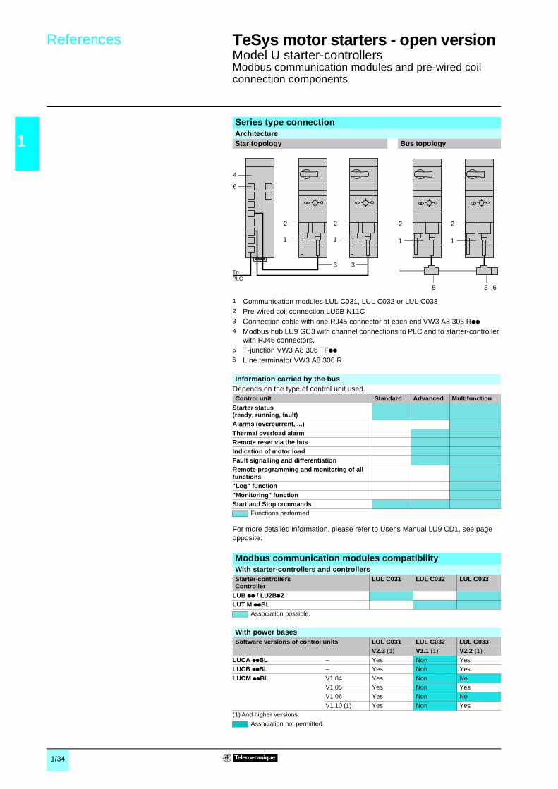
Series type connectionArchitectureStar topology Bus topology
1 Communication modules LUL C031, LUL C032 or LUL C0332 Pre-wired coil connection LU9B N11C3 Connection cable with one RJ45 connector at each end VW3 A8 306 Rpp4 Modbus hub LU9 GC3 with channel connections to PLC and to starter-controller
with RJ45 connectors,5 T-junction VW3 A8 306 TFpp6 LIne terminator VW3 A8 306 R
1
3
2
1
3
2
4
6
ToPLC
5 6
2
5
2
11
Information carried by the busDepends on the type of control unit used.Control unit Standard Advanced Multifunction
Starter status(ready, running, fault)Alarms (overcurrent, ...)Thermal overload alarmRemote reset via the busIndication of motor loadFault signalling and differentiationRemote programming and monitoring of all functions"Log" function"Monitoring" functionStart and Stop commands
Functions performed
Modbus communication modules compatibility With starter-controllers and controllersStarter-controllersController
LUL C031 LUL C032 LUL C033
LUB pp / LU2Bp2LUT M ppBL
Association possible.
With power basesSoftware versions of control units LUL C031 LUL C032 LUL C033
V2.3 (1) V1.1 (1) V2.2 (1)
LUCA ppBL – Yes Non YesLUCB ppBL – Yes Non Yes
LUCM ppBL V1.04 Yes Non NoV1.05 Yes Non YesV1.06 Yes Non No
V1.10 (1) Yes Non Yes(1) And higher versions.
Association not permitted.
1/35
1
References 1 TeSys motor starters - open version 1
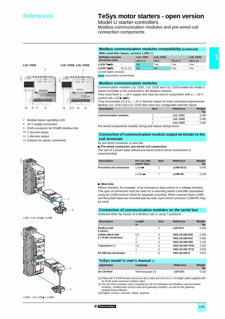
Model U starter-controllersModbus communication modules and pre-wired coil connection components
Communication modules LUL C031, LUL C032 and LUL C033 enable the model U starter-controller to be connected to the Modbus network.They must have a c 24 V supply and must be used in conjunction with a c 24 V control unit, LUCp ppBL.They incorporate a 0.5 A, c 24 V discrete output for local command requirements. Module LUL C032 and LUL C033 also have two configurable discrete inputs.
Pre-wired components simplify wiring and reduce wiring errors.
By pre-wired connector or wire link.b Pre-wired connector: pre-wired coil connectionThe use of a power base without pre-wired control circuit connections is recommended.
b Wire link:Allows insertion, for example, of an emergency stop control or a voltage interface.This type of connection must be used for a reversing starter-controller assembled using an LU6M reverser block for separate mounting. When reverser block LU6M and the power base are mounted side-by-side, a pre-wired connector LU9M RC may be used.
Achieved either by means of a Modbus hub or using T-junctions.
Modbus communication modules compatibility (continued)With controller bases, version 1.200 (1) Software versions of control units
LUL C031 LUL C032 LUL C033V2.3 (1) V1.1 V1.2 (1) V2.1 (1)
LUCB TppBL – No Yes Yes Yes
LUCM TppBL V2.11 (1) No No Yes Yes(1) And higher versions.
Association not permitted.
Modbus communication modules
Description Item Reference Weightkg
Communication modules 1 LUL C031 0.0801 LUL C032 0.080
1 LUL C033 0.080
5351
76
LUL C032, LUL C033
5351
75
LUL C031
7 Module status signalling LED8 24 V supply connection9 RJ45 connector for RS485 Modbus link10 2 discrete inputs11 1 discrete output12 Outputs for starter commands
1
2
5208
10
LUB + LUL C03p + LU9B
1
7
5208
11
LU2B + LUL C03p + LU9M
Connection of communication module output terminals to the coil terminals
Description For use with power base
Item Reference Weightkg
Pre-wired coil connection LUB pp 2 LU9B N11C 0.045
LU2B pp 7 LU9M RC 0.030
Connection of communication modules on the serial bus
Description Lengthm
Item Reference Weightkg
Modbus hub8 slaves
– 4 LU9 GC3 0.260
Cables fitted with2 x RJ45 connectors
0.3 3 VW3 A8 306 R03 0.0451 3 VW3 A8 306 R10 0.065
3 3 VW3 A8 306 R30 0.125T-junctions (1) 0.3 5 VW3 A8 306 TF03 0.032
1 5 VW3 A8 306 TF10 0.032
RS 485 line terminator – 6 VW3 A8 306 R 0.012
TeSys model U user's manual (2)
Application Language Reference Weightkg
On CD-Rom Multi-language (3) LU9 CD1 0.022
(1) Fitted with 2 RJ45 female connectors (bus side) and a 0.3 m or 1 m length cable supplied with an RJ45 male connector (station side).
(2) The CD-Rom contains user's manuals for the AS-Interface and Modbus communication modules, multifunction control units and gateway modules, as well as the gateway programming software.
(3) English, French, German, Italian, Spanish.
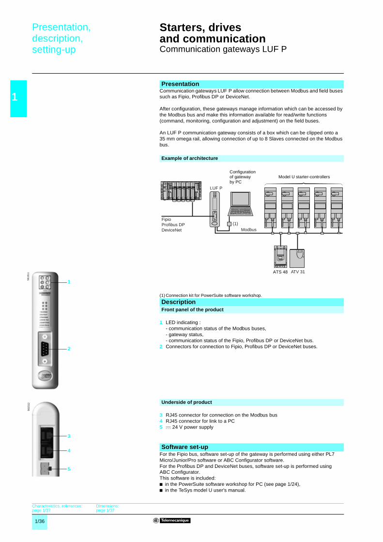
1/36
1
Presentation,description,setting-up 1
Starters, drivesand communication 1
Communication gateways LUF P
Communication gateways LUF P allow connection between Modbus and field buses such as Fipio, Profibus DP or DeviceNet.
After configuration, these gateways manage information which can be accessed by the Modbus bus and make this information available for read/write functions (command, monitoring, configuration and adjustment) on the field buses.
An LUF P communication gateway consists of a box which can be clipped onto a 35 mm omega rail, allowing connection of up to 8 Slaves connected on the Modbus bus.
(1) Connection kit for PowerSuite software workshop.
For the Fipio bus, software set-up of the gateway is performed using either PL7 Micro/Junior/Pro software or ABC Configurator software.For the Profibus DP and DeviceNet buses, software set-up is performed using ABC Configurator.This software is included:b in the PowerSuite software workshop for PC (see page 1/24),b in the TeSys model U user's manual.
Presentation
Example of architecture
Modbus
ATV 31
LUF P
ATS 48
FipioProfibus DPDeviceNet
(1)
Configurationof gatewayby PC
Model U starter-controllers
DescriptionFront panel of the product
1 LED indicating :- communication status of the Modbus buses,- gateway status,- communication status of the Fipio, Profibus DP or DeviceNet bus.
2 Connectors for connection to Fipio, Profibus DP or DeviceNet buses.
Underside of product
3 RJ45 connector for connection on the Modbus bus4 RJ45 connector for link to a PC5 c 24 V power supply
5615
1156
1512
1
2
3
5
4Software set-up
Characteristics, references:page 1/37
Dimensions:page 1/37
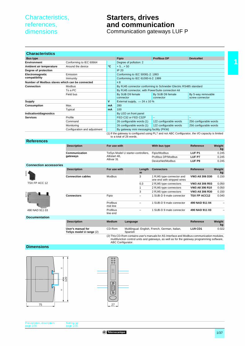
1/37
1
Characteristics,references,dimensions 1
Starters, drivesand communication 1
Communication gateways LUF P
CharacteristicsBus type Fipio Profibus DP DeviceNet
Environment Conforming to IEC 60664 Degree of pollution: 2
Ambient air temperature Around the device °C + 5…+ 50Degree of protection IP 20
Electromagneticcompatibility
Emission Conforming to IEC 50081-2: 1993Immunity Conforming to IEC 61000-6-2: 1999
Number of Modbus slaves which can be connected y 8
Connection Modbus By RJ45 connector conforming to Schneider Electric RS485 standardTo a PC By RJ45 connector, with PowerSuite connection kit
Field bus By SUB D9 female connector
By SUB D9 female connector
By 5-way removablescrew connector
Supply V External supply, c 24 ± 10 %
Consumption Max. mA 280Typical mA 100
Indication/diagnostics By LED on front panelServices Profile FED C32 or FED C32P – –
Command 26 configurable words (1) 122 configurable words 256 configurable words
Monitoring 26 configurable words (1) 122 configurable words 256 configurable wordsConfiguration and adjustment By gateway mini messaging facility (PKW)
(1) If the gateway is configured using PL7 and not ABC Configurator, the I/O capacity is limited to a total of 26 words.
ReferencesDescription For use with With bus type Reference Weight
kgCommunicationgateways
TeSys Model U starter-controllers,Altistart 48,Altivar 31
Fipio/Modbus LUF P1 0.245Profibus DP/Modbus LUF P7 0.245
DeviceNet/Modbus LUF P9 0.245
Connection accessoriesDescription For use with Length
mConnectors Reference Weight
kgConnection cables Modbus 3 1 RJ45 type connector and
one end with stripped wiresVW3 A8 306 D30 0.150
0.3 2 RJ45 type connectors VW3 A8 306 R03 0.0501 2 RJ45 type connectors VW3 A8 306 R10 0.050
3 2 RJ45 type connectors VW3 A8 306 R30 0.150Connectors Fipio – 1 SUB-D 9 male connector TSX FP ACC12 0.040
Profibus mid line
– 1 SUB-D 9 male connector 490 NAD 911 04 –
Profibus line end
– 1 SUB-D 9 male connector 490 NAD 911 03 –
DocumentationDescription Medium Language Reference Weight
kgUser's manual forTeSys model U range (2)
CD-Rom Multilingual: English, French, German, Italian, Spanish
LU9 CD1 0.022
(2) This CD-Rom contains user's manuals for AS-Interface and Modbus communication modules, multifunction control units and gateways, as well as for the gateway programming software, ABC Configurator.
Dimensions
8226
31
TSX FP ACC 12
490 NAD 911 03
8227
13
75 27
120
==
Presentation, description:page 1/36
Setting-up:page 1/36
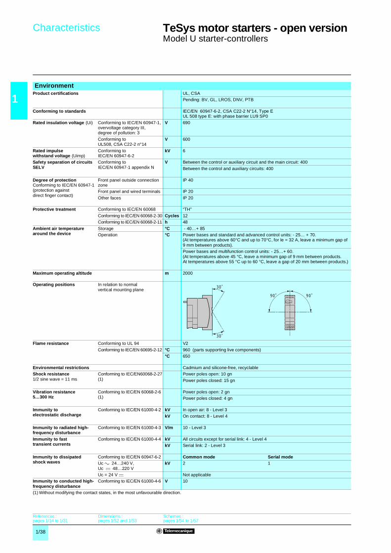
1/38
1
Characteristics 1 TeSys motor starters - open version 1
Model U starter-controllers
EnvironmentProduct certifications UL, CSA
Pending: BV, GL, LROS, DNV, PTB
Conforming to standards IEC/EN 60947-6-2, CSA C22-2 N°14, Type EUL 508 type E: with phase barrier LU9 SP0
Rated insulation voltage (Ui) Conforming to IEC/EN 60947-1, overvoltage category III,degree of pollution: 3
V 690
Conforming to UL508, CSA C22-2 n°14
V 600
Rated impulse withstand voltage (Uimp)
Conforming to IEC/EN 60947-6-2
kV 6
Safety separation of circuits SELV
Conforming to IEC/EN 60947-1 appendix N
V Between the control or auxiliary circuit and the main circuit: 400
Between the control and auxiliary circuits: 400
Degree of protectionConforming to IEC/EN 60947-1(protection against direct finger contact)
Front panel outside connection zone
IP 40
Front panel and wired terminals IP 20
Other faces IP 20
Protective treatment Conforming to IEC/EN 60068 “TH”
Conforming to IEC/EN 60068-2-30 Cycles 12Conforming to IEC/EN 60068-2-11 h 48
Ambient air temperature around the device
Storage °C - 40…+ 85Operation °C Power bases and standard and advanced control units: - 25… + 70.
(At temperatures above 60°C and up to 70°C, for Ie = 32 A, leave a minimum gap of 9 mm between products).Power bases and multifunction control units: - 25…+ 60. (At temperatures above 45 °C, leave a minimum gap of 9 mm between products. At temperatures above 55 °C up to 60 °C, leave a gap of 20 mm between products.)
Maximum operating altitude m 2000
Operating positions In relation to normal vertical mounting plane
Flame resistance Conforming to UL 94 V2
Conforming to IEC/EN 60695-2-12 °C 960 (parts supporting live components)°C 650
Environmental restrictions Cadmium and silicone-free, recyclableShock resistance1/2 sine wave = 11 ms
Conforming to IEC/EN60068-2-27(1)
Power poles open: 10 gn
Power poles closed: 15 gn
Vibration resistance5…300 Hz
Conforming to IEC/EN 60068-2-6(1)
Power poles open: 2 gnPower poles closed: 4 gn
Immunity to electrostatic discharge
Conforming to IEC/EN 61000-4-2 kV In open air: 8 - Level 3kV On contact: 8 - Level 4
Immunity to radiated high-frequency disturbance
Conforming to IEC/EN 61000-4-3 V/m 10 - Level 3
Immunity to fast transient currents
Conforming to IEC/EN 61000-4-4 kV All circuits except for serial link: 4 - Level 4kV Serial link: 2 - Level 3
Immunity to dissipated shock waves
Conforming to IEC/EN 60947-6-2 Common mode Serial modeUc a 24…240 V,Uc c 48…220 V
kV 2 1
Uc = 24 V c Not applicableImmunity to conducted high-frequency disturbance
Conforming to IEC/EN 61000-4-6 V 10
(1) Without modifying the contact states, in the most unfavourable direction.
30˚
30˚
90˚ 90˚
References :pages 1/14 to 1/31
Dimensions : pages 1/52 and 1/53
Schemes : pages 1/54 to 1/57

1/39
1
Characteristics 1 TeSys motor starters - open version 1
Model U starter-controllersPower bases and control units
Power base and control unit type LUB 12 + LUCAor LUCB or LUCCor LUCD
LUB 32 + LUCAor LUCB or LUCCor LUCD
LUB 12 + LUCM
LUB 32 + LUCM
LU2MLU6M
Power circuit connection characteristicsConnection to Ø 4 mm screw clamp terminals
Flexible cablewithout cable end
1 conductor mm2 2.5…10 2.5…10 2.5…10 2.5…10 2.5…10
2 conductors mm2 1.5…6 1.5…6 1.5…6 1.5…6 1.5…6Flexible cablewith cable end
1 conductor mm2 1…6 1…6 1…6 1…6 1…6
2 conductors mm2 1…6 1…6 1…6 1…6 1…6Solid cablewithout cable end
1 conductor mm2 1…10 1…10 1…10 1…10 1…10
2 conductors mm2 1…6 1…6 1…6 1…6 1…6Screwdriver Philips n° 2 or flat screwdriver: Ø 6 mmTightening torque N.m 1.9…2.5 1.9…2.5 1.9…2.5 1.9…2.5 1.9…2.5
Control circuit connection characteristicsConnection to Ø 3 mm screw clamp terminals
Flexible cablewithout cable end
1 conductor mm2 0.75…1.5 0.75…1.5 0.75…1.5 0.75…1.5 0.75…1.52 conductors mm2 0.75…1.5 0.75…1.5 0.75…1.5 0.75…1.5 0.75…1.5
Flexible cablewith cable end
1 conductor mm2 0.34…1.5 0.34…1.5 0.34…1.5 0.34…1.5 0.34…1.52 conductors mm2 0.34…1.5 0.34…1.5 0.34…1.5 0.34…1.5 0.34…1.5
Solid cablewithout cable end
1 conductor mm2 0.75…1.5 0.75…1.5 0.75…1.5 0.75…1.5 0.75…1.5
2 conductors mm2 0.75…1.5 0.75…1.5 0.75…1.5 0.75…1.5 0.75…1.5Screwdriver Philips n° 1 or flat screwdriver: Ø 5 mm
Tightening torque N.m 0.8…1.2 0.8…1.2 0.8…1.2 0.8…1.2 0.8…1.2
Control circuit characteristicsRated voltageof control circuit
a 50/60 Hz V 24…240 24…240 – – –c V 24…220 24…220 24 24 –
Voltage limits c 24 V (1) V 20…27 20…27 20…28 20…28 –
Operation a 24 V V 20…26.5 20…26.5 – – –a or c 48…72 V V a 38.5…72. c 38.5…93 – – –
a 110…240 V V a 88…264 a 88…264 – – – c 110…220 V V c 88…242 c 88…242 – – –
Drop-out c 24 V V 14.5 14.5 14.5 14.5 –a 24 V V 14.5 14.5 – – –a or c 48…72 V V 29 29 – – –
a 110…240 V, c 110…220 V V 55 55 – – –Typical consumption c 24 V mA 130 220 150 200 120
I max while closing a 24 V mA 140 220 – – 2360a or c 48…72 V mA 280 280 – – 2300a 110…240 V, c 110…220 V mA 280 280 – – 1000
I rms sealed c 24 V mA 60 80 70 75 120a 24 V mA 70 90 – – (2)
a or c 48…72 V mA 35 45 – – (2)a 110…240 V, c 110…220 V mA 35 25 – – (2)
Heat dissipation W 2 3 1.7 1.8 –Operating time Closing ms 24 V : 70 ; 48 V : 60 ; ≥ 72 V : 50 75 65 –
Opening ms 35 35 35 35 –
Resistance to micro-breaks ms 3 3 3 3 –Resistance to voltage drops IEC/EN 61000-4-11 At least 70 % of Uc for 500 ms –
Mechanical durability In millions of operating cycles 15 15 15 15 –Maximum operating rate In operating cycles per hour 3600 3600 3600 3600 –
Main pole characteristicsNumber of poles 3 3 3 3 –Isolation functionTo IEC/EN 60947-1
Possible Yes Yes Yes Yes –
Padlocking 1 padlock with Ø 6.9 mm shank –Rated thermal current A 12 32 12 32 –
Rated operating current (Ue ≤ 440V)
To IEC/EN 60947-6-2
In cat. AC-41 θ ≤ 70°C: 12A θ ≤ 70°C: 32A θ ≤ 55°C: 12A θ ≤ 55°C: 32A –In cat. AC-43 θ ≤ 70°C: 12A θ ≤ 70°C: 32A θ ≤ 55°C: 12A θ ≤ 55°C 32A –
Rated operating voltage V 690 (3) 690 (3) 690 (3) 690 (3) –Frequency limits Of the operating current Hz 40…60 40…60 40…60 40…60 –Power dissipated in the power circuits
Operating current A 3 6 9 12 18 25 32 –
Power dissipated in all three poles W 0.1 0.3 0.6 1.1 2.4 4.6 7.5 –Rated breaking capacity on short-circuit V 230 440 500 690 –
kA 50 50 10 4 –Total breaking time ms 2 2 2 –Thermal stress limit With Isc max on 440 V kA²s 90 120 90 120 –
(1) Voltage with maximum ripple of ± 10 %.(2) No consumption sealed. (3) For 690 V, use phase barrier LU9 SP0.
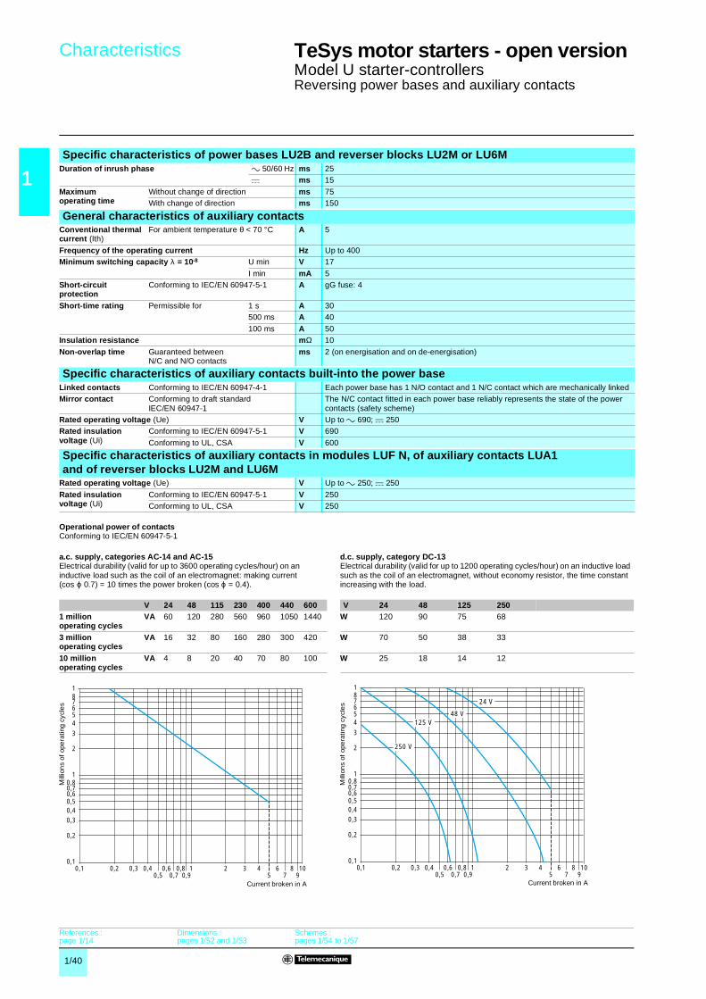
1/40
1
Characteristics 1 TeSys motor starters - open version 1
Model U starter-controllersReversing power bases and auxiliary contacts
Specific characteristics of power bases LU2B and reverser blocks LU2M or LU6MDuration of inrush phase a 50/60 Hz ms 25
c ms 15
Maximum operating time
Without change of direction ms 75With change of direction ms 150
General characteristics of auxiliary contactsConventional thermal current (Ith)
For ambient temperature θ < 70 °C A 5
Frequency of the operating current Hz Up to 400Minimum switching capacity λ = 10-8 U min V 17
I min mA 5Short-circuit protection
Conforming to IEC/EN 60947-5-1 A gG fuse: 4
Short-time rating Permissible for 1 s A 30500 ms A 40
100 ms A 50Insulation resistance mΩ 10
Non-overlap time Guaranteed between N/C and N/O contacts
ms 2 (on energisation and on de-energisation)
Specific characteristics of auxiliary contacts built-into the power baseLinked contacts Conforming to IEC/EN 60947-4-1 Each power base has 1 N/O contact and 1 N/C contact which are mechanically linkedMirror contact Conforming to draft standard
IEC/EN 60947-1The N/C contact fitted in each power base reliably represents the state of the power contacts (safety scheme)
Rated operating voltage (Ue) V Up to a 690; c 250Rated insulation voltage (Ui)
Conforming to IEC/EN 60947-5-1 V 690
Conforming to UL, CSA V 600
Specific characteristics of auxiliary contacts in modules LUF N, of auxiliary contacts LUA1and of reverser blocks LU2M and LU6M
Rated operating voltage (Ue) V Up to a 250; c 250
Rated insulation voltage (Ui)
Conforming to IEC/EN 60947-5-1 V 250Conforming to UL, CSA V 250
Operational power of contactsConforming to IEC/EN 60947-5-1
a.c. supply, categories AC-14 and AC-15Electrical durability (valid for up to 3600 operating cycles/hour) on an inductive load such as the coil of an electromagnet: making current (cos ϕ 0.7) = 10 times the power broken (cos ϕ = 0.4).
d.c. supply, category DC-13Electrical durability (valid for up to 1200 operating cycles/hour) on an inductive load such as the coil of an electromagnet, without economy resistor, the time constant increasing with the load.
V 24 48 115 230 400 440 600 V 24 48 125 2501 million operating cycles
VA 60 120 280 560 960 1050 1440 W 120 90 75 68
3 million operating cycles
VA 16 32 80 160 280 300 420 W 70 50 38 33
10 million operating cycles
VA 4 8 20 40 70 80 100 W 25 18 14 12
0,1 0,2 0,3 0,40,5
0,60,7
0,80,9
1 2 3 45
67
8910
0,1
0,2
0,30,4
0,60,5
0,80,7
7
1
2
3
54
6
81
Mill
ion
s of
ope
ratin
g c
ycle
s
Current broken in A
0,1 0,2 0,3 0,40,5
0,60,7
0,80,9
1 2 3 45
67
8910
0,1
0,2
0,30,4
0,60,5
0,80,7
7
1
2
3
54
6
81
48 V
250 V
125 V
24 V
Mill
ion
s of
ope
ratin
g c
ycle
s
Current broken in A
References :page 1/14
Dimensions : pages 1/52 and 1/53
Schemes : pages 1/54 to 1/57
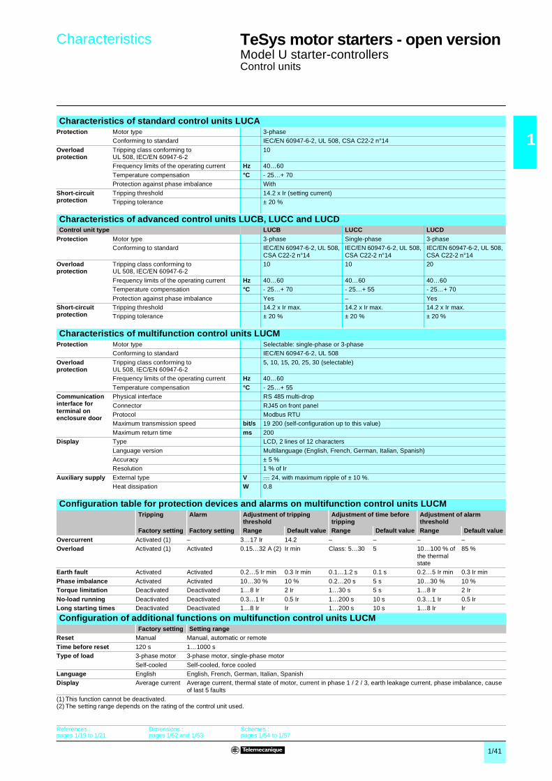
1/41
1
Characteristics 1 TeSys motor starters - open version 1
Model U starter-controllersControl units
Characteristics of standard control units LUCAProtection Motor type 3-phase
Conforming to standard IEC/EN 60947-6-2, UL 508, CSA C22-2 n°14
Overload protection
Tripping class conforming toUL 508, IEC/EN 60947-6-2
10
Frequency limits of the operating current Hz 40…60
Temperature compensation °C - 25…+ 70Protection against phase imbalance With
Short-circuit protection
Tripping threshold 14.2 x Ir (setting current)Tripping tolerance ± 20 %
Characteristics of advanced control units LUCB, LUCC and LUCDControl unit type LUCB LUCC LUCD
Protection Motor type 3-phase Single-phase 3-phaseConforming to standard IEC/EN 60947-6-2, UL 508,
CSA C22-2 n°14IEC/EN 60947-6-2, UL 508, CSA C22-2 n°14
IEC/EN 60947-6-2, UL 508, CSA C22-2 n°14
Overload protection
Tripping class conforming toUL 508, IEC/EN 60947-6-2
10 10 20
Frequency limits of the operating current Hz 40…60 40…60 40…60Temperature compensation °C - 25…+ 70 - 25…+ 55 - 25…+ 70
Protection against phase imbalance Yes – YesShort-circuit protection
Tripping threshold 14.2 x Ir max. 14.2 x Ir max. 14.2 x Ir max.Tripping tolerance ± 20 % ± 20 % ± 20 %
Characteristics of multifunction control units LUCMProtection Motor type Selectable: single-phase or 3-phase
Conforming to standard IEC/EN 60947-6-2, UL 508
Overload protection
Tripping class conforming toUL 508, IEC/EN 60947-6-2
5, 10, 15, 20, 25, 30 (selectable)
Frequency limits of the operating current Hz 40…60
Temperature compensation °C - 25…+ 55Communication interface for terminal on enclosure door
Physical interface RS 485 multi-drop
Connector RJ45 on front panelProtocol Modbus RTUMaximum transmission speed bit/s 19 200 (self-configuration up to this value)
Maximum return time ms 200Display Type LCD, 2 lines of 12 characters
Language version Multilanguage (English, French, German, Italian, Spanish)Accuracy ± 5 %Resolution 1 % of Ir
Auxiliary supply External type V c 24, with maximum ripple of ± 10 %.Heat dissipation W 0.8
Configuration table for protection devices and alarms on multifunction control units LUCMTripping Alarm Adjustment of tripping
thresholdAdjustment of time before tripping
Adjustment of alarm threshold
Factory setting Factory setting Range Default value Range Default value Range Default valueOvercurrent Activated (1) – 3…17 Ir 14.2 – – – –Overload Activated (1) Activated 0.15…32 A (2) Ir min Class: 5…30 5 10…100 % of
the thermal state
85 %
Earth fault Activated Activated 0.2…5 Ir min 0.3 Ir min 0.1…1.2 s 0.1 s 0.2…5 Ir min 0.3 Ir min
Phase imbalance Activated Activated 10…30 % 10 % 0.2…20 s 5 s 10…30 % 10 %Torque limitation Deactivated Deactivated 1…8 Ir 2 Ir 1…30 s 5 s 1…8 Ir 2 Ir
No-load running Deactivated Deactivated 0.3…1 Ir 0.5 Ir 1…200 s 10 s 0.3…1 Ir 0.5 IrLong starting times Deactivated Deactivated 1…8 Ir Ir 1…200 s 10 s 1…8 Ir Ir
Configuration of additional functions on multifunction control units LUCMFactory setting Setting range
Reset Manual Manual, automatic or remote
Time before reset 120 s 1…1000 sType of load 3-phase motor 3-phase motor, single-phase motor
Self-cooled Self-cooled, force cooledLanguage English English, French, German, Italian, SpanishDisplay Average current Average current, thermal state of motor, current in phase 1 / 2 / 3, earth leakage current, phase imbalance, cause
of last 5 faults(1) This function cannot be deactivated.(2) The setting range depends on the rating of the control unit used.
References :pages 1/19 to 1/21
Dimensions : pages 1/52 and 1/53
Schemes : pages 1/54 to 1/57
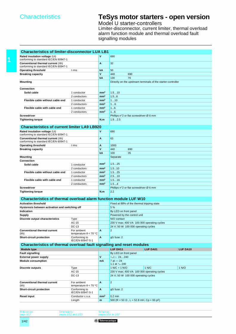
1/42
1
Characteristics 1 TeSys motor starters - open version 1
Model U starter-controllersLimiter-disconnector, current limiter, thermal overload alarm function module and thermal overload fault signalling modules
Characteristics of limiter-disconnector LUA LB1Rated insulation voltage (Ui)conforming to standard IEC/EN 60947-1
V 690
Conventional thermal current (Ith)conforming to standard IEC/EN 60947-1
A 32
Operating threshold I rms kA 50
Breaking capacity V 440 690kA 130 70
Mounting Directly on the upstream terminals of the starter-controller
ConnectionSolid cable 1 conductor mm2 1.5…10
2 conductors mm2 1.5...6
Flexible cable without cable end 1 conductor mm2 1…102 conductors mm2 1…6
Flexible cable with cable end 1 conductor mm2 1...6
2 conductors mm2 1...6Screwdriver Phillips n°2 or flat screwdriver Ø 6 mm
Tightening torque N.m 1.9…2.5
Characteristics of current limiter LA9 LB920Rated insulation voltage (Ui)conforming to standard IEC/EN 60947-1
V 690
Conventional thermal current (Ith)conforming to standard IEC/EN 60947-1
A 63
Operating threshold I rms A 1000Breaking capacity V 440 690
kA 100 35
Mounting SeparateConnection
mm2 1.5…25Solid cable 1 conductor2 conductors mm2 1.5...10
Flexible cable without cable end 1 conductor mm2 1.5…25
2 conductors mm2 2.5…10Flexible cable with cable end 1 conductor mm2 1.5…16
2 conductors mm2 1.5…4Screwdriver Phillips n°2 or flat screwdriver Ø 6 mm
Tightening torque N.m 2.2
Characteristics of thermal overload alarm function module LUF W10Activation threshold Fixed at 88% of the thermal tripping stateHysteresis between activation and switching off 5 %
Indication By LED on front panelSupply Powered by the control unitDiscrete output characteristics Type N/O contact
AC-15 230 V max; 400 VA 100 000 operating cyclesDC-13 24 V; 50 W 100 000 operating cycles
Conventional thermal current(Ith)
For ambient temperature θ < 70 °C
A 2
Short-circuit protection Conforming to IEC/EN 60947-5-1
A gG fuse: 2
Characteristics of thermal overload fault signalling and reset modulesModule type LUF DH11 LUF DA01 LUF DA10
Fault signalling By LED on front panel
External power supply V a/c 24…240Module consumption mA 7 at c 24
1.1 at a 240
Discrete outputs Type 1 N/C + 1 N/O 1 N/C 1 N/OAC-15 230 V max; 400 VA 100 000 operating cycles
DC-13 24 V; 50 W 100 000 operating cycles
Conventional thermal current(Ith)
For ambient temperature θ < 70 °C
A 2
Short-circuit protection Conforming to IEC/EN 60947-5-1
A gG fuse: 2
Reset input Conductor c.s.a. mm2 0.2 minLength m 500 (R = 50 Ω , L = 52.8 mH, Cp = 93 pF)
References :page 1/17
Dimensions : pages 1/52 and 1/53
Schemes : pages 1/54 to 1/57

1/43
1
Characteristics 1 TeSys motor starters - open version 1
Model U starter-controllersFunction modules and communication modules
Characteristics of motor load indication function module LUF V2Analogue output 4 - 20 mASignal delivered Value of I average/Ir ratio within the range of 0 to 2 for LUCB and LUCD
Value of I average/Ir ratio within the range of 0 to 3 for LUCCLoad impedance Minimum kΩ –
Maximum Ω 500Typical Ω 100
Signal characteristics with advanced control unit
Precision ± 6 %
Signal characteristics with multifunction control unit
Precision ± 10 %
Resolution 1 % of IrSupply External c 24 V
Characteristics of AS-Interface communication modules ASILUF C5 and ASILUF C51Modules type ASILUF C5 ASILUF C51
Product certification AS-Interface V2.1 n° 52901 AS-Interface V2.1 n° 52303
AS-Interface profile 7.D.F.0 7.A.7.EAmbient air temperature °C Operation - 25…+ 70
Cycle time ms 5 10AS-Interface supply V 29.5...31.5Current consumption By the AS-Interface system mA Normal operation: 25
mA Fault condition: 30On 24 V supply for the outputs mA 200
Auxiliary supply V c 24 ± 30 %Number of outputs 2 dedicated to starter-controller coil operation
Switching capacity of the solid state outputs 0.5 A/24 V (outputs protected against short-circuits)Indication/diagnostics By 2 LEDs on front panel
Characteristics of Modbus communication modules LUL C03pModule type LUL C031 LUL C032 and LUL C033
Physical interface RS 485 multi-drop
Connector RJ45 on front panelProtocol Modbus RTU
Maximum transmission speed bit/s 19 200 (self-configuration up to this value)Maximum return time ms 30Addressing By switches: from 0...31
Ambient air temperature °C Operation - 25…+ 55Logic inputs Number – 2 (to be assigned according to configuration)
Supply V – c 24Input current mA – 7
Nominal input values Voltage V c 24 (positive logic)
Current mA 7Response time Change to state 1 ms 10 (± 30 %)
Change to state 0 ms 10 (± 30 %)Input type Resistive
Solid state outputs Number 3, of which 2 dedicated to starter-controller coil operationSupply V c 24Max. current mA 500
Protection gI fuse A 1Current consumption On 24 V supply for the outputs mA 200
Switching capacity of the solid state outputs 0.5 A/24 VIndication/diagnostics By 3 LEDs on front panel
Connection characteristicsModule type LUF W10,
DH11, DA01 and DA10
LUF V2 ASILUF C5 and ASILUF C51 LUL C031LUL C032LUL C033
LUFC 00Inputs and 24 V auxiliary
Outputs
Connectors Pitch 5.08 3.81 5.08 3.81 3.81 3.81
Flexible cable without cable end 1 conductor mm² 0.2…1.5 0.14…1 0.2…1.5 0.14…1 0.14…1 0.14…12 identical conductors mm² 0.2…1 0.14…0.75 0.2…1 0.14…0.75 0.14…0.75 0.14…0.75
Flexible cable with cable end
Without insulated ferrule
1 conductor mm² 0.25…1.5 0.25…1 0.25…1.5 0.25…1 0.25…1 0.25…1
2 identical conductors mm² 0.25…1 0.25…0.34 0.25…1 0.25…0.34 0.25…0.34 0.25…0.34With insulated ferrule
1 conductor mm² 0.25…1.5 0.25…0.5 0.25…1.5 0.25…0.5 0.25…0.5 0.25…0.5
2 identical conductors(Use a double cable end)
mm² 0.5…1 0.5 0.5…1 0.5 0.5 0.5
Solid cable without cable end 1 conductor mm² 0.2…1.5 0.14…1 0.2…1.5 0.14…1 0.14…1 0.14…1
2 identical conductors mm² 0.2…1 0.14…0.5 0.2…1 0.14…0.5 0.14…0.5 0.14…0.5Conductor size 1 conductor AWG 24 to
AWG 16AWG 26 to AWG 16
AWG 24 to AWG 16
AWG 26 to AWG 16
AWG 26 to AWG 16
AWG 26 to AWG 16
Tightening torque N.m 0.5…0.6 0.22…0.25 0.5…0.6 0.22…0.25 0.22…0.25 0.22…0.25Flat screwdriver mm 3.5 2.5 3.5 2.5 2.5 2.5

1/44
1
Characteristics 1 TeSys control components 1
Model U controllersControl bases and control units
EnvironmentControl base and control unit type LUT M + LUCB T1BL or LUCD T1BL
without LUL CLUT M + LUCM T1BL or LUL C
Product certifications UL, CSAPending: BV, GL, LROS, DNV, PTB
Conforming to standards IEC/EN 60947-4-1, UL 508, CSA C22-2 N°14
Rated insulation voltage of the outputs(Ui)
Conforming to IEC/EN 60947-1, overvoltage category III, degree of pollution: 3
V 250
Conforming to UL508, CSA C22-2 n°14
V 250
Rated impulse withstand voltage of the outputs (Uimp)
Conforming to IEC/EN 60947-4-1 kV 4
Degree of protectionTo IEC/EN 60947-1(protection against direct finger contact)
Front panel (outside connection zone) IP 40Front panel and wired terminals IP 20
Other faces IP 20
Protective treatment Conforming to IEC/EN 60068 “TH”
Conforming to IEC/EN 60068-2-30 Cycles 12
Conforming to IEC/EN 60068-2-11 h 48Ambient air temperature around the device
Storage °C - 40…+ 85
Operation °C - 25…+ 70 - 25…+ 60Maximum operating altitude m 2000
Operating positionsWithout derating
In relation to normal vertical mounting plane
Flame resistance Conforming to UL 94 V2Conforming to IEC/EN 60695-2-12 °C 960 (parts supporting live components)
°C 650
Shock resistance1/2 sine wave = 11 ms
Conforming to IEC/EN60068-2-27(1)
15 gn
Vibration resistance5…300 Hz
Conforming to IEC/EN 60068-2-6(1)
4 gn
Immunity to electrostatic discharge
Conforming to IEC/EN 61000-4-2 kV In open air: 8 - Level 3kV On contact: 6 - Level 3
Immunity toradiated fields
Conforming to IEC/EN 61000-4-3 V/m 10 - Level 3
Immunity to fast transient currents
Conforming to IEC/EN 61000-4-4 kV CT outputs and inputs: 4 - Level 4kV Inputs and supply: 2 - Level 3
Immunity to radio electrical fields
Conforming to IEC/EN 61000-4-6 V 10
Control base and control unit relaysImmunity to dissipated shock waves
Conforming to IEC/EN 60947-4-1 Common mode Serial mode
Output relays / power line kV 4 2Inputs kV 2 1
Serial communication kV 2 –
(1) Without modifying the contact states, in the most unfavourable direction.
30˚
30˚
90˚ 90˚
References : page 1/27
Dimensions : page 1/27
Schemes : page 1/27
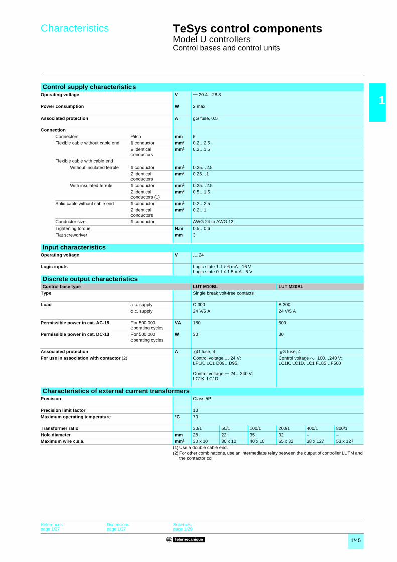
1/45
1
Characteristics 1 TeSys control components 1
Model U controllersControl bases and control units
(1) Use a double cable end.(2) For other combinations, use an intermediate relay between the output of controller LUTM and
the contactor coil.
Control supply characteristicsOperating voltage V c 20.4…28.8
Power consumption W 2 max
Associated protection A gG fuse, 0.5
ConnectionConnectors Pitch mm 5Flexible cable without cable end 1 conductor mm2 0.2…2.5
2 identical conductors
mm2 0.2…1.5
Flexible cable with cable end
Without insulated ferrule 1 conductor mm2 0.25…2.52 identical conductors
mm2 0.25…1
With insulated ferrule 1 conductor mm2 0.25…2.52 identical conductors (1)
mm2 0.5…1.5
Solid cable without cable end 1 conductor mm2 0.2…2.52 identical conductors
mm2 0.2…1
Conductor size 1 conductor AWG 24 to AWG 12Tightening torque N.m 0.5…0.6
Flat screwdriver mm 3
Input characteristicsOperating voltage V c 24
Logic inputs Logic state 1: I u 6 mA - 16 VLogic state 0: I y 1.5 mA - 5 V
Discrete output characteristicsControl base type LUT M10BL LUT M20BL
Type Single break volt-free contacts
Load a.c. supply C 300 B 300
d.c. supply 24 V/5 A 24 V/5 A
Permissible power in cat. AC-15 For 500 000 operating cycles
VA 180 500
Permissible power in cat. DC-13 For 500 000 operating cycles
W 30 30
Associated protection A gG fuse, 4 gG fuse, 4
For use in association with contactor (2) Control voltage c 24 V:LP1K, LC1 D09…D95.
Control voltage c 24…240 V:LC1K, LC1D.
Control voltage a 100…240 V: LC1K, LC1D, LC1 F185…F500
Characteristics of external current transformersPrecision Class 5P
Precision limit factor 10
Maximum operating temperature °C 70
Transformer ratio 30/1 50/1 100/1 200/1 400/1 800/1
Hole diameter mm 28 22 35 32 – –Maximum wire c.s.a. mm2 30 x 10 30 x 10 40 x 10 65 x 32 38 x 127 53 x 127
References : page 1/27
Dimensions : page 1/27
Schemes : page 1/29
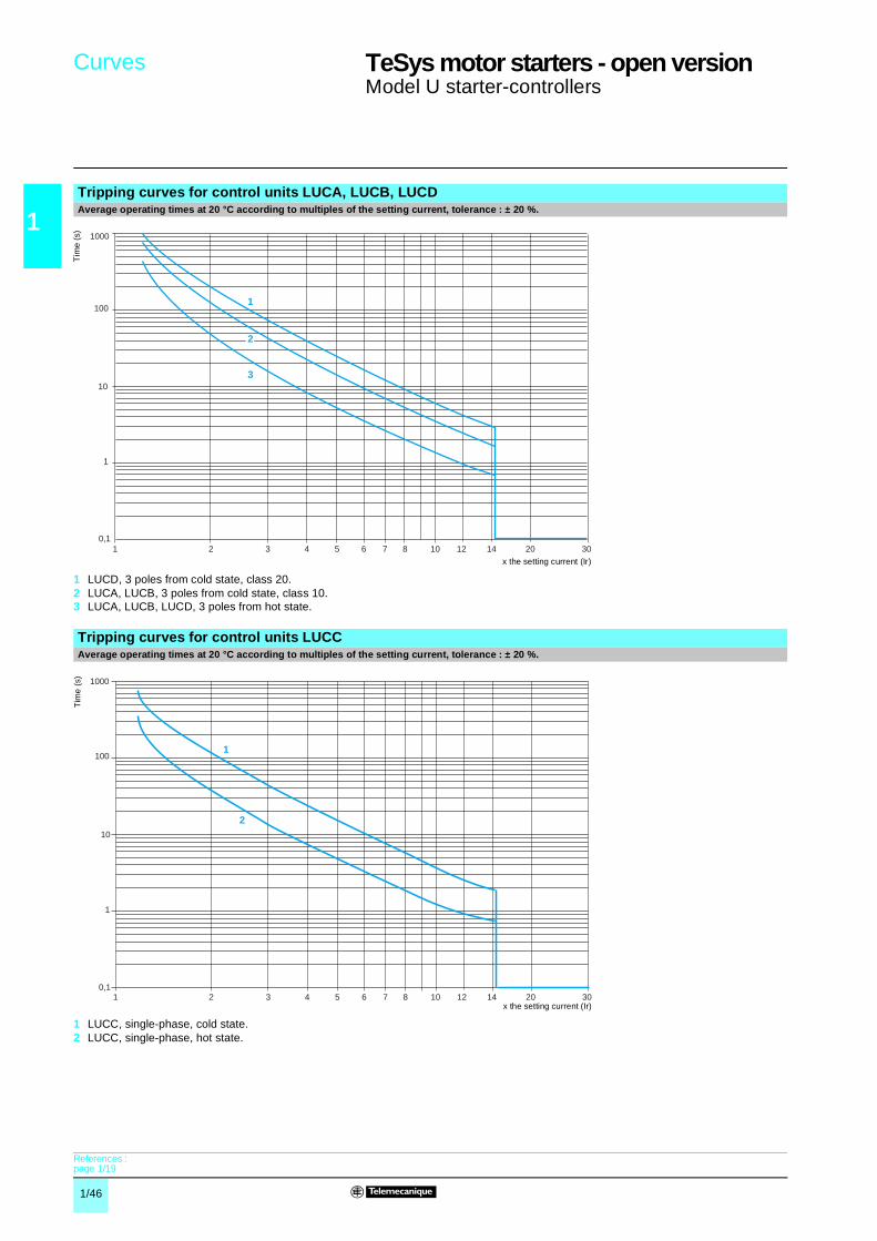
1/46
1
Curves 1 TeSys motor starters - open version 1
Model U starter-controllers
Tripping curves for control units LUCA, LUCB, LUCDAverage operating times at 20 °C according to multiples of the setting current, tolerance : ± 20 %.
1 LUCD, 3 poles from cold state, class 20.2 LUCA, LUCB, 3 poles from cold state, class 10.3 LUCA, LUCB, LUCD, 3 poles from hot state.
Tripping curves for control units LUCCAverage operating times at 20 °C according to multiples of the setting current, tolerance : ± 20 %.
1 LUCC, single-phase, cold state.2 LUCC, single-phase, hot state.
10,1
1
10
100
1000
102 3 4 5 6 7 8 12 20 3014
1
3
2
Tim
e (s
)
x the setting current (Ir)
1 102 3 4 5 6 7 8 12 20 30140,1
1
10
100
1000
2
1
Tim
e (
s)
x the setting current (Ir)
References : page 1/19

1/47
1
Curves (continued) 1 TeSys motor starters - open version 1
Model U starter-controllers
Tripping curves for control units LUCMCold state curvesAverage operating times at 20 °C according to multiples of the setting current, tolerance : ± 20 %.
10,1
1
10
100
1000
1011
2 3 4 5 6 7 8 9 1213 15 17 19
2014 16 18
10000
30
x the setting current (Ir)
Tim
e (s
)
Class 30Class 25Class 20Class 15Class 10Class 5
References : page 1/20

1/48
1
Curves (continued) 1 TeSys motor starters - open version 1
Model U starter-controllers
Tripping curves for control units LUCMHot state curvesAverage operating times at 20 °C according to multiples of the setting current, tolerance : ± 20 %
10,1
1
10
100
1000
1011
2 3 4 5 6 7 8 9 1213 15 17 19
2014 16 18
10000
30
x the setting current (Ir)
Tim
e (s
)
Class 30Class 25Class 20Class 15Class 10Class 5
References : page 1/20

1/49
1
Curves (continued) 1 TeSys motor starters - open version 1
Model U starter-controllers
Current limitation on short-circuitUe = 460 V
1 Maximum peak current2 32 A power base3 12 A power base
Thermal limit on short-circuitUe = 460 V
1 32 A power base2 12 A power base
10,1
1
10
100
12 0,4 0,6 0,8 102 3 4 6 8 10020 30 40 60 80
1
2
3
Ma
xim
um
pe
ak c
urr
ent (
kA)
Prospective Isc (kA)
11
10
100
1000
12 0,4 0,6 0,8 102 3 4 6 8 10020 30 40 60 80
1
2
Sum
of
I²dt
(A
²s)
103
Prospective Isc (kA)
References : pages 1/14 to 1/20
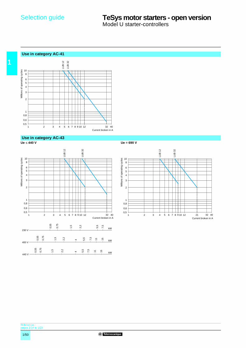
1/50
1
Selection guide 1 TeSys motor starters - open version 1
Model U starter-controllers
Use in category AC-41
Use in category AC-43Ue ≤ 440 V Ue = 690 V
21 3 4 5 6 7 8 9 10 12 32 400,5
0,6
0,8
1
2
3
5
4
6
8
10
LUB
12
LUB
32
Mill
ion
s of
op
era
ting
cyc
les
Current broken in A
21 3 4 5 6 7 8 9 10 12 32 400,5
0,6
0,8
1
2
4
5
3
6
8
10
LUB
12
LUB
32
0,55
0,75
1,5
2,2
4
5,5
7,5
230 V
400 V
0,75
0,55
1,5
2,2
4 5,5
7,5
11 15
kW
1,5
2,2
5,5
7,5
11 15
440 VkW
kW
0,55
0,75
Mill
ions
of o
pera
ting
cycl
es
Current broken in A21 3 4 5 6 7 8 9 2110 12 32 40
0,5
0,6
0,8
1
2
4
3
5
6
8
10LU
B 1
2
LUB
32
Mill
ions
of o
pera
ting
cycl
es
Current broken in A
References : pages 1/14 to 1/20

1/51
1
Selection guide 1 TeSys motor starters - open version 1
Model U starter-controllers
Use in category AC-44Ue ≤ 440 V Ue = 690 V
21 3 5 10 20 1003017080
666040
50 200
0,1
0,2
0,4
0,3
0,50,6
0,81
0,01
0,02
0,04
0,03
0,050,06
0,08
LUB
12
LUB
32
Current broken in A
Mill
ions
of o
pera
ting
cycl
es
21 3 5 10 20 100301268054
6040
50 200
0,1
0,2
0,4
0,3
0,50,6
0,81
0,01
0,02
0,04
0,03
0,050,06
0,08
LUB
12
LUB
32
Current broken in A
Mill
ions
of o
pera
ting
cycl
es
References : pages 1/14 to 1/20

1/52
1
Dimensions 1 TeSys motor starters - open version 1
Model U starter-controllers
Starter-controllersNon-reversing Reversing
Rail mounting Screw fixing Rail mounting Screw fixing
Minimum electrical clearance: X1 = 50 mm for Ue = 440 V and 70 mm for Ue = 500 and 690 V,X2 = 0(1) Maximum depth (with Modbus communication module)
Reverser block for mounting separately from power baseRail mounting Screw fixing
Sets of busbars and plug-in power socketsGV2 G445 and GV2 G454 GV2 Gppp with terminal block GV1 G09 GV2 G245 and G254
IGV2 G245 (2 x 45) 89GV2 G254 (2 x 54) 98
I P GV2 G554 GV2 G345 and G354GV2 G445 (2 x 45) 179 45
GV2 G454 (2 x 54) 206 54
aNumber of tap-offs 5 6 7 8 IGV2 G445 (2 x 45) 224 269 314 359 GV2 G345 (2 x 45) 134GV2 G454 (2 x 54) 260 314 368 422 GV2 G354 (2 x 54) 152
AK5 JB144 AK5 PC13, PC33, PC33L
126
135 (1)
154
X1
X1 45
X2
X2
126
135 (1)
73
30 Ø4
163
224
45
120/
125
233
29 Ø4
45113
115
113 36
104
Ø4
95
l
a
18
pGV1 G09
30
l
260 l
79
82
30
4581
438
452
45,5
35,538

1/53
1
Dimensions 1 TeSys motor starters - open version 1
Model U starter-controllers
Limiter-disconnector LUA LB1Disconnector LUA LB10
Current limiter LA9 LB920
(1) Maximum depth (with Modbus communication module).
Door interlock mechanismsLU9 AP00 Door cut-out
Addressing consolesXZ MC11 ASI TERV2
Modbus hub LU9 CG3Splitter box LU9 G02
135 (1) 45
9315
4
6
53,5
146
2ØM4
103
115
51
= =
==
54
54
508 11,5 8
55
230
162
Ø7
3080
209
195
84 35
128 45
154
30Ø4128
163

1/54
1
Schemes 1 TeSys motor starters - open version 1
Model U starter-controllers
Starter-controllers, 12 or 32 AWith standard, advanced or multifunction control unitNon-reversing Reversing
With control unit LUCC or LUCMConnection of a single-phase motor
Control terminal block
Reverser blocksLU2M LU6M
Control terminal blocks
With pre-wired connector LU9M RC
Control terminal block Basic scheme
S1 Start next stageS2 Electrical interlockingS3 Maintaining contactB1 Maintain forward runningB3 Maintain reverse runningA1 Pulse forward runningA2 CommonA3 Pulse reverse running(1) Electronically operated bistable
electromagnet.
Add-on contact blocks Add-on contact modulesLUA1 C11 LUA1 C20 LUFN 20 LUFN 11 LUFN 02
13/N
O
14/N
O
21/N
C
22/N
C
2/T
1
4/T
2
6/T
3
A1
A2
1/L1
3/L2
5/L3
Control Unit
84 8281
2/T
1
4/T
2
6/T
3
2/T
1
4/T
2
6/T
3
A3
B3
A1
B1
A2
1/L1
3/L2
5/L3
Control Unit
Pre-wired
Reverser
13/N
O
14/N
O
21/N
C
22/N
C
2 4 6
A1
A2
1 3 5
L1 L2
M
U V
Control Unit
A3
B3
A1
B1
A2
LU2B Reverser Motor Controller
1/L1
3/L2
5/L3
A3
2/T
1
4/T
2
6/T
3
B3
A1
S1
S2
S3
B1
A2 84 8281
Reverser
S1
S2
S3
A3
B3
A1
B1
A2
LU6M Reverser Block
S1
S2
S3
LU6M
LU9M RC
Reverser Block
Pre-wired coil
A3
B3
A1
B1
A2
LU2M Reverser Motor ControllerLU6M
A1
A3
A2
S1
22
A2
A1
21
1413
S3
B1
B3
S2
(1)
Re
vers
e
Fo
rwa
rd
Rev
ers
e
For
war
d
17/NO 18/NO
95/NC 96/NC
17/NO 18/NO
97/NO 98/NO
33/NO 34/NO
43/NO 44/NO 31/NC 32/NC
43/NO 44/NO 31/NC 32/NC
41/NC 42/NC

1/55
1
Schemes (continued) 1 TeSys motor starters - open version 1
Model U starter-controllers
Control unitsStandard control unit LUCA Advanced control unit (LUCB, LUCC, LUCD)
Basic scheme
1 and 2 Trips3 and 4 Electromagnet5 Power base rating6 N/C
Basic scheme
1 and 2 Trips3 and 4 Electromagnet5 Power base rating6 N/C7 Weight8 Thermal status/Set9 Reset mode/Reset10 (lm/Ir)11 Vc2 12 Vc1
Multifunction control unit LUCMControl terminal block
Basic scheme
1 and 2 Trips3 and 4 Electromagnet5 Power base rating6 N/C7 Weight8 N/C9 Weight10 (lm/Ir)11 Rx/Tx 12 Vc1
A1
A2
LUCA
1 2 3 4
tr
5 6
SensorL1
SensorL2
SensorL3
Power Base Interface
ControlA.S.I.C.
Supply and Detection of
start sequence
Thermal overload memory
A1
7 8 9 10 11 12
1 2 3 4 5 6
A2
LUCp
tr
SensorL1
SensorL2
SensorL3
Power Base Interface
ControlA.S.I.C.
Supply and Detection of
start sequence
Thermal overload memory
Interface module
Test
654
D(B
)D
(A)
+ 5
V
754
LUCM
0 V
8
24 V Aux
Multifonction Control Unit
A1
7 8 9 10 11 12
1 2 3 4 5 6
A2
LUCM
D(B)D(A)
+ 5 V0 V
ESC ENT
RS485
4578
RJ45
SensorL1
SensorL2
SensorL3
Power Base Interface
ControlA.S.I.C.
Supply and detection of
start sequence
Thermal overload memory
Interface module
Display and Parameter Entry
Supply
24 V Aux

1/56
1
Schemes (continued) 1 TeSys motor starters - open version 1
Model U starter-controllers
Function modulesAlarm Indication of motor loadLUF W10 LUFV 2
4-20 mA output
Basic scheme
Basic scheme
100 Ω < load < 500 Ω c 30 V max and 40 mA min
07 08
LUFW 10 Alarms Module
4...20 mANC
LUFV 2
24 V Aux
Analogue output Module
24 V Aux
07 08
LUFW 10
Advanced Control Unit or Multifunction Control Unit
Input interface Supply
Bistable Relay
LED
LUFV 2
4...20 mA c 24 V
Input interface Supply
Advanced Control Unit or Multifunction Control Unit
µP - Analogue/Digital converter
Isolation
Digital/Analogue converter
Voltage/Current converter
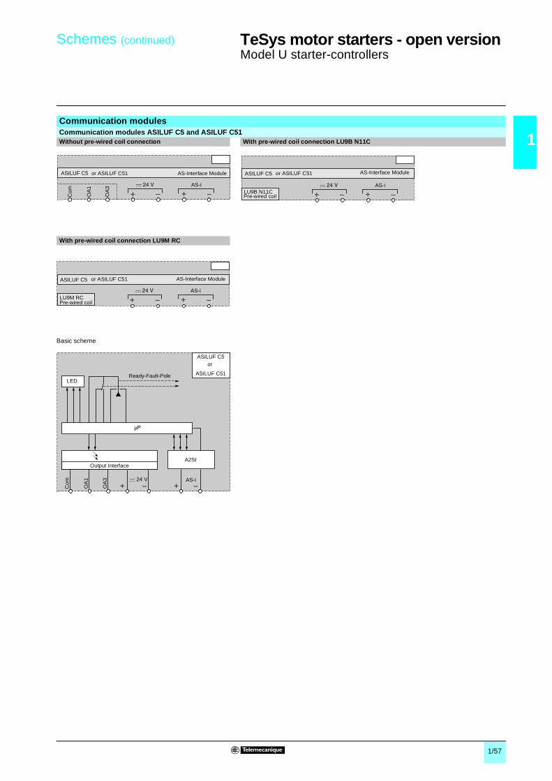
1/57
1
Schemes (continued) 1 TeSys motor starters - open version 1
Model U starter-controllers
Communication modulesCommunication modules ASILUF C5 and ASILUF C51Without pre-wired coil connection With pre-wired coil connection LU9B N11C
With pre-wired coil connection LU9M RC
Basic scheme
Com
OA
1
OA
3 AS-i
ASILUF C5 AS-Interface Moduleor ASILUF C51
AS-i
ASILUF C5
LU9B N11CPre-wired coil
AS-Interface Moduleor ASILUF C51
AS-i
ASILUF C5
LU9M RCPre-wired coil
AS-Interface Moduleor ASILUF C51
c 24 V
ASILUF C5
Com
OA
1
OA
3 AS-i
A2SI
ASILUF C51
Output Interface
Ready-Fault-PoleLED
or

1/58
1
Schemes (continued) 1 TeSys motor starters - open version 1
Model U starter-controllers
Communication modules (continued)
Modbus communication modules LUL C031 Modbus communication modules LUL C032 and LUL C033Without pre-wired coil connection Without pre-wired coil connection
With pre-wired coil connection LU9B N11C With pre-wired coil connection LU9B N11C
With pre-wired coil connection LU9M RC With pre-wired coil connection LU9M RC
Basic scheme Basic scheme
Com
OA
1
Com
LO1
OA
3
654
D(B
)D
(A)
0 V
854
LUL C031
24 V Aux
Modbus Module
Com
OA
1
LI1
LI2
LO1
OA
3
654
D(B
)D
(A)
0 V
854
LUL C032
24 Vc
Modbus Module
24 VAux COM
or LUL C033
Com
LO1
654
D(B
)D
(A)
0 V
854
LUL C031
LU9B N11C24 V Aux
Modbus Module
Pre-wired coil LI1
LI2
LO1
654
D(B
)D
(A)
0 V
854
LUL C032
LU9B N11C
Modbus Module
Pre wired coil
24 Vc
24 VAux COM
or LUL C033
Com
LO1
54
D(B
)D
(A)
0 V
854
LUL C031
LU9M RC24 V Aux
Modbus Module
Pre wired coil LI1
LI2
LO1
54
D(B
)D
(A)
0 V
854
LUL C032
LU9M RC
Modbus Module
Pre wired coil
24 Vc
24 VAux COM
or LUL C033
LULC 031
Com
Com
OA
1
OA
3
LO1
D(B)
D(A)
0 VRS485
AL1
AL2
4
5
8
ModbusRJ45
24 V
Supply
24 V Aux
Address
Input interface
Advanced Control Unit or Multifunction Control Unit
Ready-Fault-PoleLED
Output Interface
LULC 032
Com LI1
LI2
OA
1
OA
3
LO1
D(B)
D(A)
0 VRS485
AL1
AL2
4
5
8
ModbusRJ45
x 6
LULC 033
I/O interfaceSupply
Address
Control unit interface
Advanced Control Unit or Multifunction Control Unit
Ready-Fault-PoleLED
Controller interface
Output Interface
Controller
24 Vc
24 VAux COM
or

1/59
1
Schemes (continued) 1 TeSys motor starters - open version 1
Model U starter-controllers
Communication modules (continued)
Parallel wiring modulesWithout pre-wired coil connection With pre-wired coil connection LU9M RC
With pre-wired coil connection LU9B N11C
Basic scheme
87654321Com
OA
1
OA
3
LUF C00
Link // RJ45
Parallel bus Module
87654321
LUF C00
LU9M RC Link // RJ45
Parallel bus Module
Pre-wired coil
87654321
LUF C00
LU9B N11C Link // RJ45
Parallel bus Module
Pre-wired coil
Com
OA
3
OA
1
87654321
LUF C00
RJ45
PolesReady-Fault
1 Forward running2 Reverse running3 Output common4 Knob in position5 Pole state6 Reserved7 Fault8 Input common

1/60
1
Schemes (continued) 1 TeSys motor starters - open version 1
Model U starter-controllers
Communication modules (continued)
Wiring hub and splitter boxModbus hub LU9G C3 Parallel wiring splitter box LU9 G02
(1) Not connected on connectors X1 to X8. Only present on RJ45 IN and OUT connectors.(2) 20-way HE 10 input connector.(3) 20-way HE 10 output connector.(4) Correspondence between wire colours and HE 10 connector pin numbers.
GatewaysLUF P1 LUF P7 LUF P9
LU9 GC3
0 V
0 V
D (
A) +
D (
B) –
12
34
56
78
RJ 45
X1
12
34
56
78
RJ 45
X9
X2
X3
X4
X5
X6
X7
X8
X10
RJ 45
RJ 45
RJ 45
RJ 45
RJ 45
RJ 45
RJ 45
RJ 45
Sh
ield
ing
Sh
ield
ing
Sh
ield
ing
LU9 G02
c 24 V
Com
Com
12
34
56
78
910
1112
1314
1516
1718
1920
12
34
56
78
910
1112
1314
1516
1718
1920
(2)
12
34
56
78
(3)
RJ 45
X1
X2
X3
X4
X5
X6
X7
X8
X10
X9
RJ 45
RJ 45
RJ 45
RJ 45
RJ 45
RJ 45
12
34
56
78
RJ 45
Forward runningReverse runningOutput common
N/CPole state
N/CFault
Input common
Forward runningN/C
Output commonN/C
Pole stateN/C
FaultInput common
Out
puts
Inpu
ts
24 V Aux
87654321
LUF P1
X2 Fip I/O
54
D(B
)D
(A)
0 V
8549
X1
Gateway Fip I/O - Modbus
24 V Aux
87654321
LUF P7
X2 Profibus
54
D(B
)D
(A)
0 v
8549
X1
Gateway Profibus - Modbus
24 V Aux
54321
LUF P9
X2 DeviceNet
54
D(B
)D
(A)
0 V
854
X1
Gateway DeviceNet - Modbus
24 V Aux
Colours of TSX CDPppp connection cable wires (4)
1 White2 Brown3 Green4 Yellow5 Grey6 Pink7 Blue8 Red9 Black10 Violet11 Grey-pink12 Red-blue13 White-green14 Brown-green15 White-yellow16 Yellow-brown17 White-grey18 Grey-brown19 White-pink20 Pink-brown
N/CN/CN/CD (B) –D (A) +N/C24 V (1)0 V
N/C N/C N/C
D (B) –D (A) +
N/CN/C 0 V
Fault X1Fault X2Fault X3Fault X4Fault X5Fault X6Fault X7Fault X8Pole state X1Pole state X2Pole state X3Pole state X4Pole state X5Pole state X6Pole state X7Pole state X8+ 24 V Aux- 24 V Aux+ 24 V Aux- 24 V Aux
Forward running X1Forward running X2Forward running X3Forward running X4Forward running X5Forward running X6Forward running X7Forward running X8Reverse running X1Reverse running X2Reverse running X3Reverse running X4N/CN/CN/CN/C+ c 24 V- c 24 V+ c 24 V- c 24 V
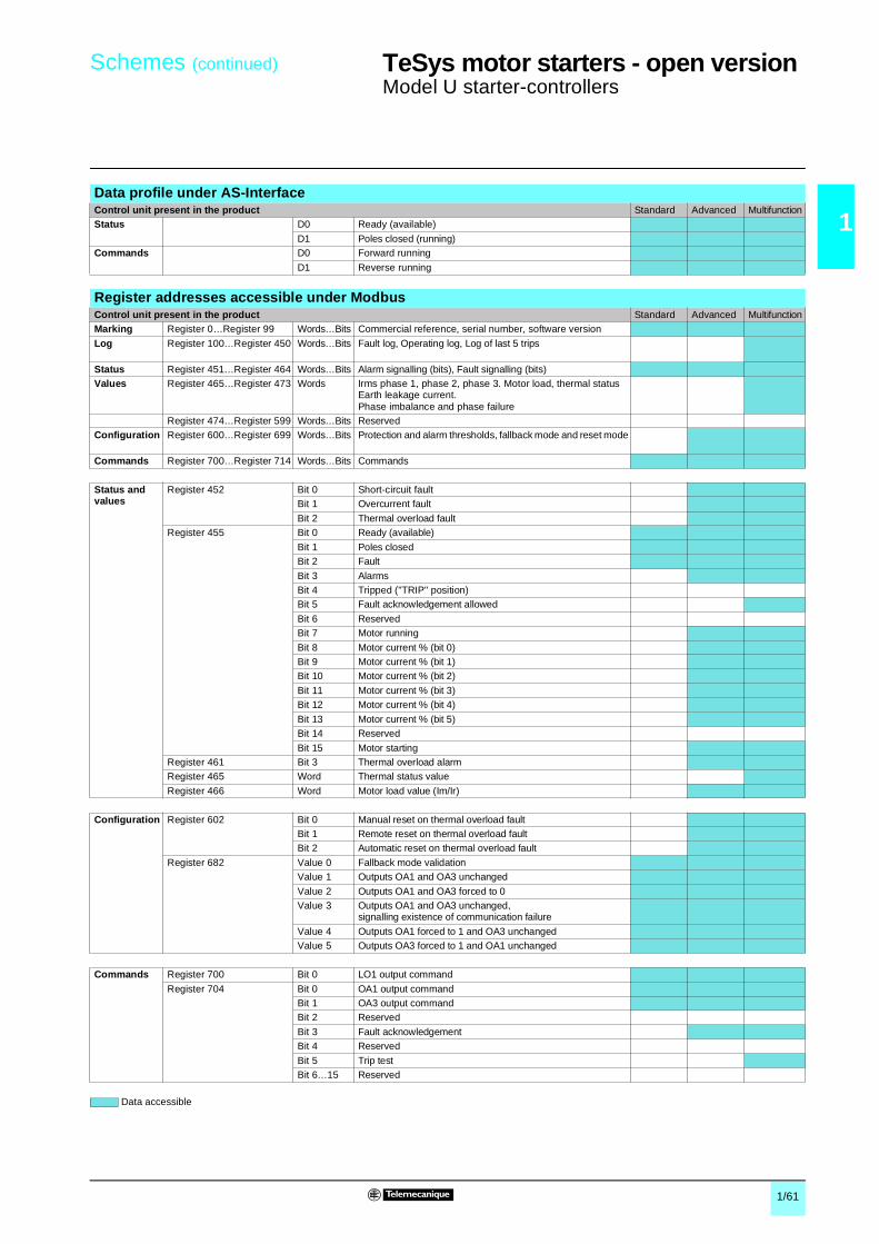
1/61
1
Schemes (continued) 1 TeSys motor starters - open version 1
Model U starter-controllers
Data accessible
Data profile under AS-InterfaceControl unit present in the product Standard Advanced MultifunctionStatus D0 Ready (available)
D1 Poles closed (running)Commands D0 Forward running
D1 Reverse running
Register addresses accessible under ModbusControl unit present in the product Standard Advanced MultifunctionMarking Register 0…Register 99 Words…Bits Commercial reference, serial number, software version
Log Register 100…Register 450 Words…Bits Fault log, Operating log, Log of last 5 trips
Status Register 451…Register 464 Words…Bits Alarm signalling (bits), Fault signalling (bits)Values Register 465…Register 473 Words Irms phase 1, phase 2, phase 3. Motor load, thermal status
Earth leakage current. Phase imbalance and phase failure
Register 474…Register 599 Words…Bits ReservedConfiguration Register 600…Register 699 Words…Bits Protection and alarm thresholds, fallback mode and reset mode
Commands Register 700…Register 714 Words…Bits Commands
Status and values
Register 452 Bit 0 Short-circuit faultBit 1 Overcurrent fault
Bit 2 Thermal overload faultRegister 455 Bit 0 Ready (available)
Bit 1 Poles closedBit 2 Fault
Bit 3 AlarmsBit 4 Tripped ("TRIP" position)Bit 5 Fault acknowledgement allowed
Bit 6 ReservedBit 7 Motor running
Bit 8 Motor current % (bit 0)Bit 9 Motor current % (bit 1)Bit 10 Motor current % (bit 2)
Bit 11 Motor current % (bit 3)Bit 12 Motor current % (bit 4)
Bit 13 Motor current % (bit 5)Bit 14 Reserved
Bit 15 Motor startingRegister 461 Bit 3 Thermal overload alarmRegister 465 Word Thermal status value
Register 466 Word Motor load value (Im/Ir)
Configuration Register 602 Bit 0 Manual reset on thermal overload faultBit 1 Remote reset on thermal overload faultBit 2 Automatic reset on thermal overload fault
Register 682 Value 0 Fallback mode validationValue 1 Outputs OA1 and OA3 unchanged
Value 2 Outputs OA1 and OA3 forced to 0Value 3 Outputs OA1 and OA3 unchanged,
signalling existence of communication failure
Value 4 Outputs OA1 forced to 1 and OA3 unchangedValue 5 Outputs OA3 forced to 1 and OA1 unchanged
Commands Register 700 Bit 0 LO1 output command
Register 704 Bit 0 OA1 output commandBit 1 OA3 output commandBit 2 Reserved
Bit 3 Fault acknowledgementBit 4 Reserved
Bit 5 Trip testBit 6…15 Reserved

1/62
1
Basic schemes 1 TeSys motor starters - open version 1
Model U starter-controllersNon-reversing
Non-reversing starter-controllers LUB
2-wire control via 2-position switch 3-wire control, pulsed start with maintaining contact
Connection of a motor load indicator module LUFV 2
Connection of thermal overload fault signalling modules LUF DA10Automatic reset Remote reset
Control via Modbus communication module LUL C031
Control via Modbus communication modules LUL C032 and LUL C033
Without pre-wired coil connection Without pre-wired coil connection
1/L1
3/L2
5/L3
2/T
1
4/T
2
6/T
3
M3 a
U1
V1
W1
Control Unit
A2A1
Start
Stop
A2A1
13 144...20 mA
NC
LUFV 2 Analogue output Module
24 V Aux24 V Aux
Z1
Z2
07 08
LUF DA10
A1
24…230 V
A2
X1
X2
– QF1
– V1
– S1
Automatic or remote reset
Z1
Z2
07 08
LUF DA10
A1
24…230 V
A2
X1
X2
– QF1 – S2
– V1
– S1
Automatic or remote reset
A1A2
Com
OA
1
Com
LO1
OA
3
654
D(B
)D
(A)
GN
D
854
Modbus
LULC 031 Modbus Module
24 V Aux
A1A2
Com
OA
1
LI1
LI2
LO1
OA
3
654
D(B
)D
(A)
GN
D
854
Modbus
LUL C032
– S2– S1
Modbus Module
24 Vc
24 VAux COM
or LUL C033

1/63
1
Basic schemes (continued) 1 TeSys motor starters - open version 1
Model U starter-controllersNon-reversing
Non-reversing starter controllers LUB (continued)
Control via communication modules ASILUF C5 and ASILUF C51Without pre-wired coil connection Without pre-wired coil connection
With local control
With pre-wired coil connection LU9B N11C Without pre-wired coil connectionWith local control
Without pre-wired coil connectionWith multifunction control unit LUCM
A1A2
Com
OA
1
OA
3
AS-Interface
ASILUF C5 AS-Interface Module
AS-Interface line
or ASILUF C51
A1A2
Com
OA
1
OA
3
AS-Interface
ASILUF C5
Adj
ustm
ent
Nor
ma
l
AS-Interface Module
AS-Interface line
or ASILUF C51
AS-Interface
ASILUF C5 AS-Interface Module
LU9B N11CPre wired coil
AS-Interface line
or ASILUF C51
A1A2
Com
OA
1
OA
3
AS-Interface
ASILUF C5A
djus
tme
nt
No
rma
l
AS-Interface Module
AS-Interface line
or ASILUF C51
A1A2
Com
OA
1
OA
3
AS-Interface
654
D(B
)D
(A)
GN
D
854
RJ45
Bus Modbus RS 485
ASILUF C5
LUCM Multifonction Control Unit
24 V Aux
AS-Interface Module
AS-Interface line
or ASILUF C51
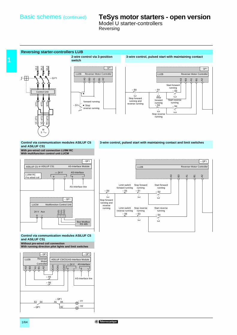
1/64
1
Basic schemes (continued) 1 TeSys motor starters - open version 1
Model U starter-controllersReversing
Reversing starter-controllers LUB2-wire control via 3-position switch
3-wire control, pulsed start with maintaining contact
Control via communication modules ASILUF C5 and ASILUF C51
3-wire control, pulsed start with maintaining contact and limit switches
With pre-wired coil connection LU9M RCWith multifunction control unit LUCM
Control via communication modules ASILUF C5 and ASILUF C51 Without pre-wired coil connectionWith running direction pilot lights and limit switches
2/T
1
4/T
2
6/T
3
2/T
1
4/T
2
6/T
3
U1
W1
V1
M 3
1/L1
3/L2
5/L3
Control Unit
A3
B3
A1
B1
A2
LU2B Reverser Motor Controller
Stop
forward running
reverse running
A3
B3
A1
B1
A2
LU2B
Stop forward running and
reverse running
Reverser Motor Controller
Stop forward running
Stop reverse running
Start forward running
Start reverse running
AS-Interface
654
D(B
)D
(A)
GN
D
854
Bus Modbus RS 485
LUCM
ASILUF C5
24 V Aux
AS-Interface Module
Multifonction Control Unit
LU9M RC Pre wired coil
AS-Interface line
or ASILUF C51
A3
B3
A1
B1
A2
LU2B
Stop forward running and
reverse running
Reverser Motor Controller
Stop forward running
Stop reverse running
Start forward running
Start reverse running
Limit switch forward running
Limit switch reverse running
53 54 81 84
82
A3
B3
A1
B1
A2
Com
OA
1
OA
3 AS-Interface
LU2B ASILUF C5/C51AS-Interface ModuleReverserMotor
Controller
AS-Interface line
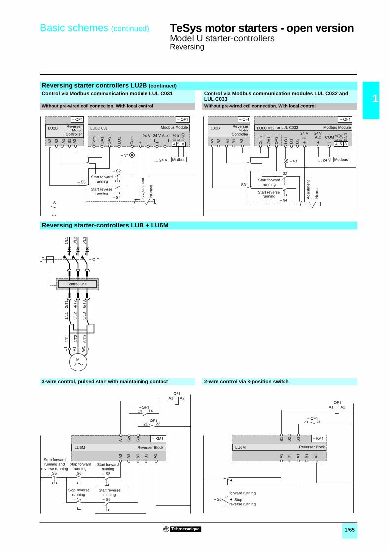
1/65
1
Basic schemes (continued) 1 TeSys motor starters - open version 1
Model U starter-controllersReversing
Reversing starter controllers LU2B (continued)
Control via Modbus communication module LUL C031 Control via Modbus communication modules LUL C032 and LUL C033
Without pre-wired coil connection. With local control Without pre-wired coil connection. With local control
Reversing starter-controllers LUB + LU6M
3-wire control, pulsed start with maintaining contact 2-wire control via 3-position switch
A3
B3
A1
B1
A2
Com
OA
1
Com
LO1
OA
3
654
D(B
)D
(A)
GN
D
854
Modbus
LU2B LULC 031 Modbus Module
24 V Aux
Ad
just
me
nt
NO
rmal
Start reverse running
Start forward running
ReverserMotor
Controller
A3
B3
A1
B1
A2
Com
OA
1
LI1
LI2
LO1
OA
3
654
D(B
)D
(A)
GN
D
854
Modbus
LU2B LULC 032 Modbus Module
Ad
just
men
t
Nor
mal
Start reverse running
Start forward running
ReverserMotor
Controller 24 Vc
24 VAux COM
or LUL C033
2/T
1
4/T
2
6/T
3
2/T
1
4/T
2
6/T
3
U1
W1
V1
M 3
1/L1
3/L2
5/L3
1/L1
3/L2
5/L3
Control Unit
A3
B3
A1
B1
A2
21 22
S1
S2
S3
13 14
A2A1
LU6M
S5 S6 S8
S7 S9
Reverser Block
Stop forward running and
reverse runningStop forward
running
Stop reverse running
Start forward running
Start reverse running
A3
B3
A1
B1
A2
21 22
S1
S2
S3
A2A1
LU6M Reverser Block
Stop
forward running
reverse running

2/0
0
2

2/1
Contents 0
2
2 - Altistart U01 soft starters and TeSys model U
b References . . . . . . . . . . . . . . . . . . . . . . . . . . . . . . . . . . . . . . . . . . . . . . . page 2/2
b Dimensions . . . . . . . . . . . . . . . . . . . . . . . . . . . . . . . . . . . . . . . . . . . . . . . page 2/3
b Schemes . . . . . . . . . . . . . . . . . . . . . . . . . . . . . . . . . . . . . . . . . . . pages 2/4 to 2/7

2/2
2
References 2 Soft startersfor asynchronous motors 2
Altistart U01 and TeSys model U
Soft start/soft stop unit for 0.75 to 15 kW motors(can be combined with the TeSys model U starter)Motor StarterMotor power (1) Nominal
currentReference Weight
230 V 230 V 400 V 460 VkW HP kW HP A kg
3-phase supply voltage: 200…480 V 50/60 Hz0.751.1
11.5
1.52.23
23
6 ATSU 01N206LT 0.340
1.5–
2–
–4
5–
9 ATSU 01N209LT 0.340
2.23
3–
5.5–
7.5–
12 ATSU 01N212LT 0.340
45.5
57.5
7.511
1015
22 ATSU 01N222LT 0.490
7.5 10 15 20 32 ATSU 01N232LT 0.490
AccessorieDescription Used for starter Reference Weight
kgPower connector between ATSU 01N2ppLT andTeSys model U
ATSU 01N2ppLT VW3 G4104 0.020
TeSys model U starter and soft start unit combinations Numerous possibilities for combinations and options are offered.Please consult the “TeSys model U Starters-open version” specialist catalogue.
Motor power Soft starter TeSys model UVoltage Power base Control unit (2)230 VkW/HP
400 VkW
460 VHP
0.75/1 1.5 2 ATSU 01N206LT LUB 12 LUCp 05BL1.1/1.5 2.2/3 3 ATSU 01N206LT LUB 12 LUCp 12BL
1.5/2 – – ATSU 01N209LT LUB 12 LUCp 12BL– 4 5 ATSU 01N209LT LUB 12 LUCp 12BL
2.2/3 – – ATSU 01N212LT LUB 12 LUCp 12BL3/– 5.5 7.5 ATSU 01N212LT LUB 32 LUCp 18BL4/5 7.5 10 ATSU 01N222LT LUB 32 LUCp 18BL
5.5/7.5 11 15 ATSU 01N222LT LUB 32 LUCp 32BL7.5/10 15 20 ATSU 01N232LT LUB 32 LUCp 32BL
Example of a starter-motor combination with:1 non-reversing power base for DOL starting (LUBp2BL)2 control unit (LUCM ppBL)3 power connector (VW3 G4104)4 Altistart U01soft start/soft stop unit (ATSU 01N2ppLT)
(1) Standard motor power ratings, HP power ratings indicated according to standard UL 508.(2) Depending on the configuration of the chosen TeSys model U starter, replace the p with A for
standard, B for expandable, and M for multifunction.
ATSU 01N222LT
DF
5317
14
1
2
4
LUBp2BL
LUCM ppBL
ATSU 01N2ppLT
3
DF
5103
62
Dimensions:page 2/3
Schemes:pages 2/4 and 2/5

2/3
2
Dimensions 2 Soft startersfor asynchronous motors 2
Altistart U01 and TeSys model U
TeSys model U combination (non-reversing power base) and ATSU 01N206LT to ATSU 01N212LT
TeSys model U combination (non-reversing or reversing power base) and ATSU 01N206LT to ATSU 01N212LT
Mounting on 5 (35 mm) rail with VW3 G4104 connector Side by side mounting
TeSys model U combination (non-reversing power base) and ATSU 01N222LT to ATSU 01N232LT
TeSys model U combination (non-reversing or reversing power base) and ATSU 01N222LT to ATSU 01N232LT
Mounting on 5 (35 mm) rail with VW3 G4104 connector Side by side mounting
VW3 G4104 connector
15028
4
45
9
99135
154
72,2
9
124
314
45
170
9
99135
72,2
154
9
44,820
646
,6
28
References:page 2/2
Schemes:pages 2/4 and 2/5
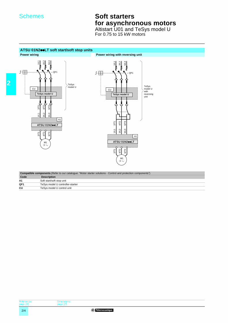
2/4
2
Schemes 2 Soft startersfor asynchronous motors 2
Altistart U01 and TeSys model UFor 0.75 to 15 kW motors
ATSU 01N2ppLT soft start/soft stop unitsPower wiring Power wiring with reversing unit
Compatible components (Refer to our catalogue: “Motor starter solutions - Control and protection components”)Code Description
A1 Soft start/soft stop unitQF1 TeSys model U controller-starterCU TeSys model U control unit
2/T
1
4/T
2
6/T
3
2/T
1
4/T
2
6/T
3
1/L1
3/L2
5/L3
1/L1
3/L2
5/L3
M1 3
A1
CU
– QF1
ATSU 01N2ppLT
TeSys model U
TeSys model U
2/T
1
4/T
2
6/T
3
2/T
1
4/T
2
6/T
3
1/L1
3/L2
5/L3
1/L1
3/L2
5/L3
M1 3
CU
– QF1
A1
ATSU 01N2ppLT
TeSys model U
TeSys model U with reversing unit
References:page 2/2
Dimensions:page 2/3
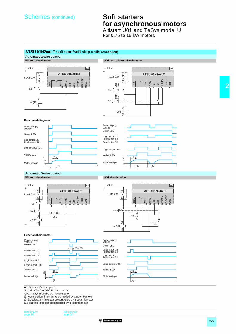
2/5
2
Schemes (continued) 2 Soft startersfor asynchronous motors 2
Altistart U01 and TeSys model UFor 0.75 to 15 kW motors
ATSU 01N2ppLT soft start/soft stop units (continued)
Automatic 2-wire control Without deceleration With and without deceleration
Functional diagrams
Automatic 3-wire control Without deceleration With deceleration
Functional diagrams
A1: Soft start/soft stop unitS1, S2: XB4 B or XB5 B pushbuttonsQF1: TeSys model U controller-startert1: Acceleration time can be controlled by a potentiometert2: Deceleration time can be controlled by a potentiometerU1: Starting time can be controlled by a potentiometer
– QF1
– S1
LUA1 C20
R1A
A1
A2
1718
R1C
LI1
LI2
+ 2
4 V
BO
OS
T
LO1
CO
MA1
+
–
c 24 V
ATSU 01N2ppLT
– QF1
– S2
A1
A2
A1+
–
c 24 V
– S1
ATSU 01N2ppLT
R1A
R1C
LI1
LI2
+ 2
4 V
BO
OS
T
LO1
CO
M
LUA1 C20
1718
Sto
pR
un
Sto
pR
un
10 s
tt1
U1
Power supplyvoltage
Green LED
Logic input LI2Pushbutton S1
Logic output LO1
Yellow LED
Motor voltaget2 tt1
10 s
U1
Power supplyvoltageGreen LED
Logic input LI2Pushbutton S2
Logic output LO1
Yellow LED
Motor voltage
Pushbutton S1
– QF1
– S2
– QF1
14 13
A1
A2
A1+
–
c 24 V
– S1
R1A
R1C
ATSU 01N2ppLT
LI1
LI2
+ 2
4 V
BO
OS
T
LO1
CO
M
LUA1 C20
1718
– QF1
– QF1
– S2
A1
1413
A2
A1+
–
c 24 V
– S1
ATSU 01N2ppLT
R1A
R1C
LI1
LI2
+ 2
4 V
BO
OS
T
LO1
CO
M
LUA1 C20
1718
500 ms
tt1
10 s
U1
Power supplyvoltageGreen LED
Pushbutton S1
Logic output LO1
Yellow LED
Motor voltage
Logic input LI2
Pushbutton S2
t
10 s
t1
Power supply voltage
Green LED
Logic output LO1
Yellow LED
Motor voltage
Logic input LI2Pushbutton S2
Logic input LI1Pushbutton S1
References:page 2/2
Dimensions:page 2/3
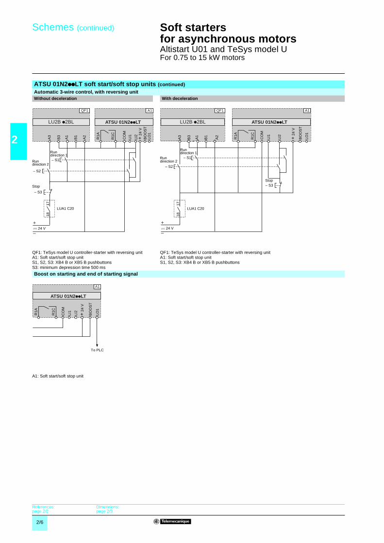
2/6
2
Schemes (continued) 2 Soft startersfor asynchronous motors 2
Altistart U01 and TeSys model UFor 0.75 to 15 kW motors
ATSU 01N2ppLT soft start/soft stop units (continued)
Automatic 3-wire control, with reversing unit Without deceleration With deceleration
QF1: TeSys model U controller-starter with reversing unitA1: Soft start/soft stop unitS1, S2, S3: XB4 B or XB5 B pushbuttonsS3: minimum depression time 500 ms
QF1: TeSys model U controller-starter with reversing unitA1: Soft start/soft stop unitS1, S2, S3: XB4 B or XB5 B pushbuttons
Boost on starting and end of starting signal
A1: Soft start/soft stop unit
A3
B3
A1
A2
B1
A1
ATSU 01N2ppLT
R1A
R1C
CO
M
BO
OS
TLO
1
LI2
LI1
+ 2
4 V
– S2
– S1
– S3
c 24 V+
–
LUA1 C20
1718
QF1
LU2B p2BL
Run direction 1
Run direction 2
Stop
A3
B3
A1
A2
B1
LU2B p2BL
A1QF1
ATSU 01N2ppLT
R1A
R1C
CO
M
BO
OS
T
LO1
LI2
LI1
+ 2
4 V
– S2
– S1
c 24 V
– S3
+
–
LUA1 C20
1718
Run direction 1
Run direction 2
Stop
A1
ATSU 01N2 LT
R1A
R1C
LI1
LI2
+ 2
4 V
BO
OS
T
LO1
CO
M
To PLC
References:page 2/2
Dimensions:page 2/3

2/7
2
Schemes (continued) 2 Soft startersfor asynchronous motors 2
Altistart U01 and TeSys model UFor 0.75 to 15 kW motors
ATSU 01N2ppLT soft start/soft stop units (continued)
Automatic control with Modbus communication module, with and without decelerationWithout reversing unit With reversing unit
Function Register Bit Value Function Register Bit ValuePowering down TeSys U and ATSU Powering up TeSys U and ATSU
– 704 0 0 Forward 704 0 1Reverse 704 1 1
Automatic control without deceleration Powering down TeSys U and ATSURun 700 0 1 Forward 704 0 0
Stop 704 0 0 Reverse 704 1 0Automatic control with deceleration Automatic control without deceleration
Run 700 0 1 Run 700 0 1
Soft stop 700 0 0 Stop forward 704 0 0Stop reverse 704 1 0
Automatic control with deceleration (forward or reverse)Run 700 0 1
Soft stop 700 0 0A1: Soft start/soft stop unit A1: Soft start/soft stop unit
QF1: TeSys model U controller-starter with reversing unit
Automatic control with AS-Interface communication module, without decelerationWithout reversing unit With reversing unit
Function Bit Value Function Bit ValuePower-up and automatic control without deceleration Power-up and automatic control without deceleration
Run D0 1 Run forward D0 1Stop D0 0 Stop D0 0
Run reverse D1 1
Stop D1 0A1: Soft start/soft stop unit A1: Soft start/soft stop unit
QF1: TeSys model U controller-starter with reversing unit
A1
LO1
CO
M D(B
)D
(A)
Gnd
A1
–+–+c 24 VLU9B N11C
LUL C031
4 5 8
ATSU 01N2ppLT
R1A
R1C
Modbus Module
CO
M
BO
OS
T
LO1
LI2
LI1
+ 2
4 V
c 24 V
+
1314
Pre-wired coil24 V Aux.
A1
LO1
CO
M D(B
)D
(A)
Gnd
A1
–+–+c 24 V
LUL C031
4 5 8OA
1
OA
3
CO
M
ATSU 01N2ppLT
R1A
R1C
Modbus Module
CO
M
BO
OS
T
LO1
LI2
LI1
+ 2
4 V
c 24 V
+
A3
B3
A1
A2
B1
LU2B p2BL
QF1
24 V Aux.
CO
M
BO
OS
T
LO1
LI2
LI1
+ 2
4 V
A1
++AS-Interfacec 24 VLU9B N11C
ASI LUFC5
ATSU 01N2ppLT
R1A
R1C
1314
c 24 V
+
Pre-wired coil
CO
M
BO
OS
T
LO1
LI2
LI1
+ 2
4 V
A1
++AS-Interfacec 24 V
ASI LUFC5
ATSU 01N2ppLT
R1A
R1C
A3
B3
A1
A2
B1
LU2B p2BL
QF1
OA
1
OA
3
CO
M
c 24 V
+
References:page 2/2
Dimensions:page 2/3

ART. 807144 01 / 2006 - V2.0
DIA
1ED
2050
405E
N
Schneider Electric Industries SAS
Head Office89, bd Franklin Roosevelt92506 Rueil-Malmaison CedexFrance
www.schneider-electric.comwww.telemecanique.com
Due to evolution of standards and equipment, the characteristics indicated in texts and images of thisdocument do not constitute a commitment on our part without confirmation.Design: Schneider ElectricPhotos: Schneider ElectricPrinted by:
Simply Smart !
The efficiency of Telemecanique branded solutionsUsed in combination, Telemecanique products provide quality solutions, meeting all your Automation & Control applications requirements.
A worldwide presence
Constantly availableb More than 5 000 points of sale in 130 countries.b You can be sure to find the range of products that are right for you and which complies fully with the standards in the country where they are used.
Technical assistance wherever you areb Our technicians are at your disposal to assist you in finding the optimum solution for your particular needs.b Schneider Electric provides you with all necessary technical assistance, throughout the world.


