O & M Manual of Thanwar Dam June 2020
Page i
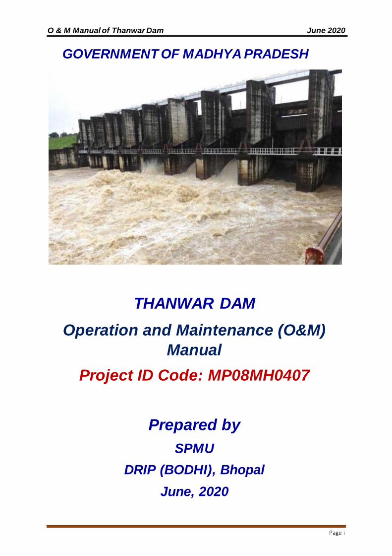
GOVERNMENT OF MADHYA PRADESH
THANWAR DAM
Operation and Maintenance (O&M)
Manual
Project ID Code: MP08MH0407
Prepared by
SPMU
DRIP (BODHI), Bhopal
June, 2020
O & M Manual of Thanwar Dam June 2020
Page ii
This page is left blank intentionally
O & M Manual of Thanwar Dam June 2020
Page iii
Government of Madhya Pradesh
Water Resources Department
Disclaimer
This Operation and Maintenance Manual for Thanwar Dam no way restricts the
dam owner in digressing from her/his responsibilities. The State Dam Safety
Organization or the Central Water Commission cannot be held responsible for the
efficacy of this manual developed based on documents provided by the dam owner.
The Dam Owner and her/his Operators must exercise appropriate discretion when
implementing and using the operation and maintenance manual for managing the
workings of the dam and appurtenant structures.
The manual was developed for the purpose of organizing and managing the
operation, inspection and maintenance of the dam for reducing risk and optimizing
performance of the dam.
Executive Engineer
Water Resources Division, Mandla, Water Resources Department District, Mandla
Ph-07642-252220 Email – [email protected]
Copy right @2019 Water Resources Department. All rights reserved. This publication is copy right
and may not be resold or reproduced in any manner without the prior consent of WRD, MP.

O & M Manual of Thanwar Dam June 2020
Page iv
This page is left blank intentionally

O & M Manual of Thanwar Dam June 2020
Page v
Government of Madhya Pradesh
Water Resources Department
PREFACE
This Operation and Maintenance (O&M) Manual for Thanwar Dam is a detailed
written description of step-by-step procedures for ensuring that the dam is safely
operated and properly maintained. Timely inspection and maintenance are
necessary for the safe functioning of the dam and continued productive use of the
dam and reservoir. The term “O&M” as employed in this manual includes operation,
inspection, maintenance and repair of dam components, replacement of equipment
and appurtenant structures, as required.
This manual is provided to assist the dam owner in management of their project in a
safe and efficient manner. The Dam Safety Bill, 2019, was passed by Lok Sabha
after the Cabinet approval. The Dam Safety Bill 2019 requires State Dam Safety
Organizations (SDSO) to keep perpetual vigilance, carry out inspections regularly,
and monitor the operation and maintenance of all dams for prevention of dam
failure related disasters and to provide for institutional mechanism to ensure their
safe functioning.
This manual was prepared following the Guidelines for preparing O&M Manuals for
dams (Doc. No. CDSO_GUD_DS_O3_v1.0) published by CWC in the year 2018
under DRIP.
Director, State Project Management Unit,
DRIP, Bhopal.

O & M Manual of Thanwar Dam June 2020
Page vi
This page is left blank intentionally

O & M Manual of Thanwar Dam June 2020
Page vii
Team Members Involved in Preparing this O&M Manual.
Shri G. P. Soni
Chief Engineer BODHI
Water Resources Department,
Bhopal.
Overall review & Approval
Shri Rajesh Shrivastava Chief Engineer,
Wainganga Basin, Seoni Reviewer
Shri B. P. Dubey
Director, State Project
Management Unit,
DRIP, Bhopal.
Reviewer
Shri P. K. Gupta
Superintending Engineer,
Water Resources Circle, Jabalpur
Reviewer
Shri B. K. Singh
Executive Engineer,
Water Resources Division, Mandla
Reviewer
Shri C. S. Dhurvey
Sub Divisional Officer
Water Resources Sub Division, Water Resources Division,
Mandla
Assisted in making available all
necessary information.
Shri Makrand Golwalkar Deputy Director, SPMU, DRIP,
Bhopal Prepared original
Draft
Ms Shweta Kushwaha Assistant Director, SPMU,
DRIP, Bhopal Prepared original
Draft
Shri Sameer Soni Assistant Director, SPMU,
DRIP, Bhopal Prepared original
Draft
Shri Sanjay Agrawal Assistant Director, SPMU,
DRIP, Bhopal
Prepared original
Draft

O & M Manual of Thanwar Dam June 2020
Page viii
This page is left blank intentionally

O & M Manual of Thanwar Dam June 2020
Page ix
Contents
Disclaimer ................................................................................................................................iii
PREFACE................................................................................................................................. v
Team Members Involved in Preparing this O&M Manual. ............................................... vii
CHAPTER 1 GENERAL INFORMATION ............................................................................ 1
1.1. Purpose, Location, Description of Dam: ........................................................... 1
1.1.1.Purpose ......................................................................................................... 1
1.1.2.Description of dam....................................................................................... 1
1.2. Assignment of Responsibility: ............................................................................ 2
1.3. Collection &Reporting of Dam and Reservoir Data: ....................................... 2
1.4. Public Utilities and Safety: .................................................................................. 3
1.5. Restricted Area ..................................................................................................... 3
1.6. Communication& Warning system: ................................................................... 3
1.6.1.Communication system: ............................................................................. 3
1.6.2.Warning System:.......................................................................................... 3
1.7. Distribution of Operation & Maintenance Manual: .......................................... 4
1.8. List of Supporting Documents & Reference Material: .................................... 4
1.9. Schedule of duties for operating personnel: .................................................... 5
CHAPTER 2 PROJECT OPERATION................................................................................ 7
2.1. Basic data: ............................................................................................................. 7
2.1.2. Area capacity curve.................................................................................... 9
2.1.3. Data of Historic floods .............................................................................. 10
2.1.4. Latest Design Inflow Flood and Flood Routing Studies: .................... 11
2.2. Operation Plan: ................................................................................................... 11
2.3 Normal Operation Procedures:.......................................................................... 12
2.3.1. Rule Curve/Reservoir Operations. ........................................................ 12
2.3.2. Discharge through gated spillway for different reservoir levels. ..... 12
2.3.3. Operating instructions for gates and hoists of irrigation outlet. ....... 13
2.3.4. Methodology to work out gate opening for passing the required discharge through the irrigation outlet at different reservoir levels. ..................... 16
2.3.5. Safety Aspects: ......................................................................................... 18
2.4. Emergency Operation: ....................................................................................... 18
2.5. Reservoir Capacities: ......................................................................................... 18
2.6. Record Keeping: ................................................................................................. 18
CHAPTER 3.PROJECT INSPECTION ............................................................................. 21
3.1. Objective of Dam inspection: ............................................................................ 21
3.2. Types of Dam Safety Inspections: ................................................................... 21
3.2.1. Informal Inspections ................................................................................. 21
3.2.2. Scheduled Inspections:............................................................................ 22
O & M Manual of Thanwar Dam June 2020
Page x
3.2.3. Special (Unscheduled) Inspections: ...................................................... 23
3.2.4 Comprehensive Evaluation Inspections: ................................................ 23
3.2.4.1. Details to be provided to DSRP before inspection:.......................... 24
CHAPTER 4 PROJECT MAINTENANCE ........................................................................ 27
4.1. Maintenance Plan:.............................................................................................. 27
4.2. Maintenance Priorities: ...................................................................................... 27
4.2.1. Immediate Maintenance .......................................................................... 27
4.2.2. Condition based maintenance ................................................................ 27
4.2.3. Routine Maintenance ............................................................................... 28
4.3. Procedures for undertaking routine Maintenance works:............................. 28
4.3.1. Earth work in earthen dam ...................................................................... 28
4.3.2. Upstream Riprap ....................................................................................... 30
4.3.3.Controlling Vegetation............................................................................... 31
4.3.4. Controlling Animal Damage .................................................................... 31
4.3.5. Controlling Ants and Termites (White Ants) ......................................... 32
4.3.6. Controlling Damage from Vehicular Traffic .......................................... 32
4.3.7. Masonry/Concrete Spillway (Surplus Escape)..................................... 33
4.3.8. Gates and Hoisting Equipments............................................................. 33
4.3.8.1. Radial Gates........................................................................................... 35
4.3.8.2 Electrically operated fixed hoists.......................................................... 37
4.3.8.3 Maintenance of Electrical components of Fixed Rope Drum Hoists39
4.3.9. Electrical System: ..................................................................................... 46
4.3.10. Metal Component maintenance: .......................................................... 46
4.3.11. Access Road: .......................................................................................... 46
4.4. Material Requirements during monsoon period: ........................................... 48
4.5. Establishment structure at Thanwar dam. ...................................................... 48
4.6. Preparation of O&M Budget:............................................................................. 49
4.7. Maintenance of records: .................................................................................... 49
CHAPTER 5 INSTRUMENTATION AND MONITORING ...................................... ……51
CHAPTER 6: PREVIOUS REHABILITATION EFFORTS. ............................................ 53
CHAPTER 7: UPDATING THE MANUAL. ....................................................................... 57
7.1 Training and Exercises: ...................................................................................... 57
Appendix-I Scheduled Dam Safety Inspection Form: ..................................................... 59
Appendix-II: Checklist of various instruments installed on large dams: ...................... 93
Appendix-III: Summary Table for Annual O&M Budget: ................................................ 97
Appendix- IV: Emergency Action Plan .................................................................... 99
2. Dam Owner’s Responsibilities ......................................................................................100
4. Responsibilities for Notification.......................................................................... 103
5. Responsibilities for Evacuation......................................................................... 105
O & M Manual of Thanwar Dam June 2020
Page xi
Police Department(s) Responsibilities............................................................ 106
Fire Department(s), Army & Navy Forces Responsibilities......................... 106
6. Responsibilities for Termination and Follow-Up ............................................. 106
Appendix-IV: Basic Drawings of the Dam &Spillway. .................................... .. ……. 111
1. Index Map: ........................................................................................................... 113
2. Satellite map and Layout Plan of Thanwar Dam:.......................................... 114
3. Location Map: ..................................................................................................... 115
4. X-Cross section of dam: .................................................................................... 116
5. X-Cross section of Spillway of dam:................................................................ 117
6. L-Section of Dam:............................................................................................... 118
7. Area Capacity Curve:......................................................................................... 119
Appendix-VI: References ........................................................................................ 120
Appendix-VII: Glossary............................................................................................ 121
List of Tables
Table 1 – Assignment of Responsibilities…………………………………………………
2
Table 2- Schedule of Duties for operating personnel……………………………………… 5
Table 3- Area Capacity Curve……………………………………………………………… 9
Table 4- Data of Historic Floods………………………………………………… ………… 10
Table 5- Discharge through gated spillway for different reservoir levels…………… 12
Table 6- Inspection Schedules……………………………………………………………… 22
Table 7 a- Radial Gates and Screw Hoists………………………………………………...
Table 7 b- Head Regulator Gates and Screw Hoists………………………………………
44
45
Table 8- Frequency of measurements……………………………………………………… 51
Table 9- Dam Owner’s Responsibilities…………………………………………………… 100
Table 10- Responsibilities for Notification………………………………………………… 103
Table 11- Termination and Follow-up Responsibilities …………………………………. 107

O & M Manual of Thanwar Dam June 2020
Page xii
This page is left blank intentionally
O & M Manual of Thanwar Dam June 2020
Page 1
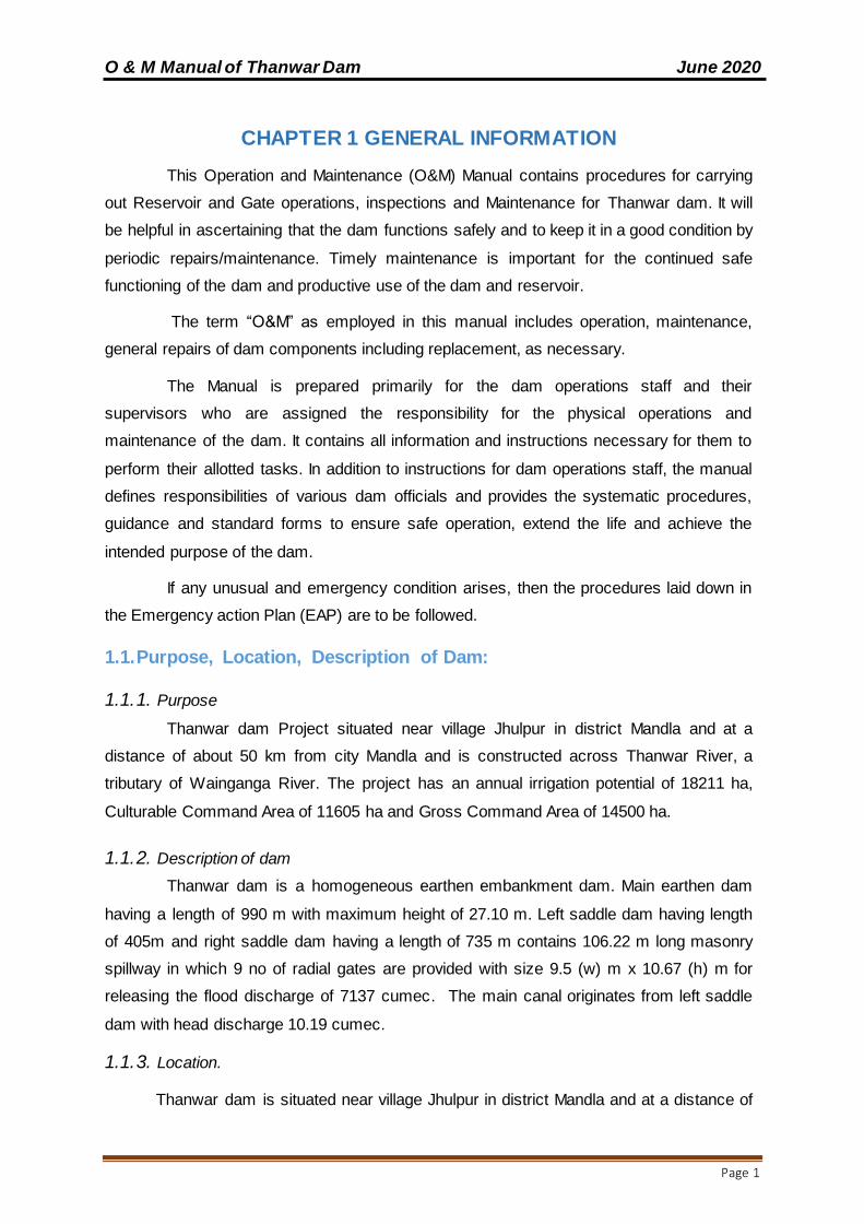
CHAPTER 1 GENERAL INFORMATION
This Operation and Maintenance (O&M) Manual contains procedures for carrying
out Reservoir and Gate operations, inspections and Maintenance for Thanwar dam. It will
be helpful in ascertaining that the dam functions safely and to keep it in a good condition by
periodic repairs/maintenance. Timely maintenance is important for the continued safe
functioning of the dam and productive use of the dam and reservoir.
The term “O&M” as employed in this manual includes operation, maintenance,
general repairs of dam components including replacement, as necessary.
The Manual is prepared primarily for the dam operations staff and their
supervisors who are assigned the responsibility for the physical operations and
maintenance of the dam. It contains all information and instructions necessary for them to
perform their allotted tasks. In addition to instructions for dam operations staff, the manual
defines responsibilities of various dam officials and provides the systematic procedures,
guidance and standard forms to ensure safe operation, extend the life and achieve the
intended purpose of the dam.
If any unusual and emergency condition arises, then the procedures laid down in
the Emergency action Plan (EAP) are to be followed.
1.1.Purpose, Location, Description of Dam:
1.1.1. Purpose
Thanwar dam Project situated near village Jhulpur in district Mandla and at a
distance of about 50 km from city Mandla and is constructed across Thanwar River, a
tributary of Wainganga River. The project has an annual irrigation potential of 18211 ha,
Culturable Command Area of 11605 ha and Gross Command Area of 14500 ha.
1.1.2. Description of dam
Thanwar dam is a homogeneous earthen embankment dam. Main earthen dam
having a length of 990 m with maximum height of 27.10 m. Left saddle dam having length
of 405m and right saddle dam having a length of 735 m contains 106.22 m long masonry
spillway in which 9 no of radial gates are provided with size 9.5 (w) m x 10.67 (h) m for
releasing the flood discharge of 7137 cumec. The main canal originates from left saddle
dam with head discharge 10.19 cumec.
1.1.3. Location.
Thanwar dam is situated near village Jhulpur in district Mandla and at a distance of

O & M Manual of Thanwar Dam June 2020
Page 2
about 50 km from city Mandla. Its latitude is 220-34’-54” N and longitude is 800-04’-33’’E. It
is located in Wainganga Basin.
The dam site is approachable by all-weather motorable road from SH-44 which is at
a distance of 8 km from it. Pindrai Railway Station is nearest railway station at a distance of
12 km from the dam site. Jabalpur airport is 127 km away from project site.
1.2.Assignment of Responsibility:
Table 1
Sl. No.
Function Officers having responsibility
1. Project Administration-Officer-in-Charge Executive Engineer, Water Resources Division, Mandla
2. Operations of Equipment at the dam Assistant Engineer/SDO (Civil), Water Resources Division, Mandla
5. Authorizing releases for irrigation and water supply,
Executive Engineer, Water Resources Division, Mandla
6. Recording reservoir data Assistant Engineer/SDO, Water Resources Division, Mandla
7. Routine inspection
Assistant Engineer/SDO Water Resources Division, Mandla
& Executive Engineer, Water Resources Division, Mandla
8. Maintenance
Assistant Engineer/SDO, Water Resources Division, Mandla
&Executive Engineer, Water Resources Division, Mandla
9. Dam safety surveillance including instrumentation. Executive Engineer, Water Resources Division, Mandla
1.3.Collection &Reporting of Dam and Reservoir Data:
Routine data for the following is to be recorded
Reservoir water surface elevation – on daily basis during non-monsoon and hourly
basis during monsoon
Spillway outflow on hourly basis during monsoon.
Irrigation releases on daily basis.
Hydro – Meteorological data on daily basis.
Surveillance and monitoring
O & M Manual of Thanwar Dam June 2020
Page 3
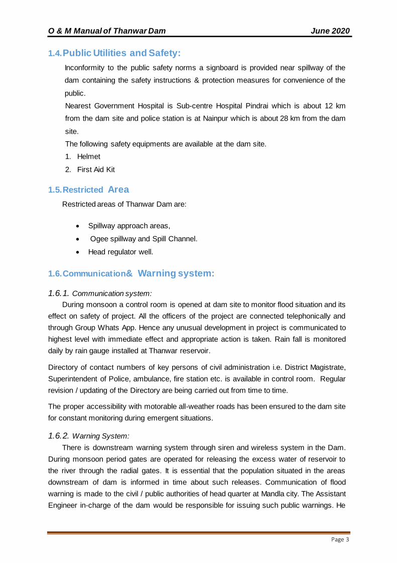
1.4.Public Utilities and Safety:
Inconformity to the public safety norms a signboard is provided near spillway of the
dam containing the safety instructions & protection measures for convenience of the
public.
Nearest Government Hospital is Sub-centre Hospital Pindrai which is about 12 km
from the dam site and police station is at Nainpur which is about 28 km from the dam
site.
The following safety equipments are available at the dam site.
1. Helmet
2. First Aid Kit
1.5.Restricted Area
Restricted areas of Thanwar Dam are:
Spillway approach areas,
Ogee spillway and Spill Channel.
Head regulator well.
1.6.Communication& Warning system:
1.6.1. Communication system:
During monsoon a control room is opened at dam site to monitor flood situation and its
effect on safety of project. All the officers of the project are connected telephonically and
through Group Whats App. Hence any unusual development in project is communicated to
highest level with immediate effect and appropriate action is taken. Rain fall is monitored
daily by rain gauge installed at Thanwar reservoir.
Directory of contact numbers of key persons of civil administration i.e. District Magistrate,
Superintendent of Police, ambulance, fire station etc. is available in control room. Regular
revision / updating of the Directory are being carried out from time to time.
The proper accessibility with motorable all-weather roads has been ensured to the dam site
for constant monitoring during emergent situations.
1.6.2. Warning System:
There is downstream warning system through siren and wireless system in the Dam.
During monsoon period gates are operated for releasing the excess water of reservoir to
the river through the radial gates. It is essential that the population situated in the areas
downstream of dam is informed in time about such releases. Communication of flood
warning is made to the civil / public authorities of head quarter at Mandla city. The Assistant
Engineer in-charge of the dam would be responsible for issuing such public warnings. He
O & M Manual of Thanwar Dam June 2020
Page 4
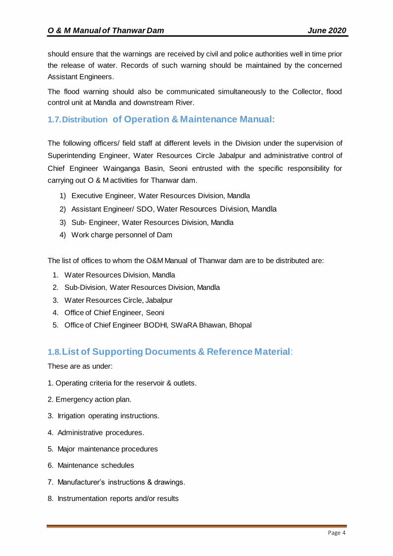
should ensure that the warnings are received by civil and police authorities well in time prior
the release of water. Records of such warning should be maintained by the concerned
Assistant Engineers.
The flood warning should also be communicated simultaneously to the Collector, flood
control unit at Mandla and downstream River.
1.7.Distribution of Operation & Maintenance Manual:
The following officers/ field staff at different levels in the Division under the supervision of
Superintending Engineer, Water Resources Circle Jabalpur and administrative control of
Chief Engineer Wainganga Basin, Seoni entrusted with the specific responsibility for
carrying out O & M activities for Thanwar dam.
1) Executive Engineer, Water Resources Division, Mandla
2) Assistant Engineer/ SDO, Water Resources Division, Mandla
3) Sub- Engineer, Water Resources Division, Mandla
4) Work charge personnel of Dam
The list of offices to whom the O&M Manual of Thanwar dam are to be distributed are:
1. Water Resources Division, Mandla
2. Sub-Division, Water Resources Division, Mandla
3. Water Resources Circle, Jabalpur
4. Office of Chief Engineer, Seoni
5. Office of Chief Engineer BODHI, SWaRA Bhawan, Bhopal
1.8.List of Supporting Documents & Reference Material:
These are as under:
1. Operating criteria for the reservoir & outlets.
2. Emergency action plan.
3. Irrigation operating instructions.
4. Administrative procedures.
5. Major maintenance procedures
6. Maintenance schedules
7. Manufacturer’s instructions & drawings.
8. Instrumentation reports and/or results
O & M Manual of Thanwar Dam June 2020
Page 5
9. Report on design flood review and flood routing study carried out under DRIP
10. All drawings of the dam (Civil, Mechanical, Electrical)
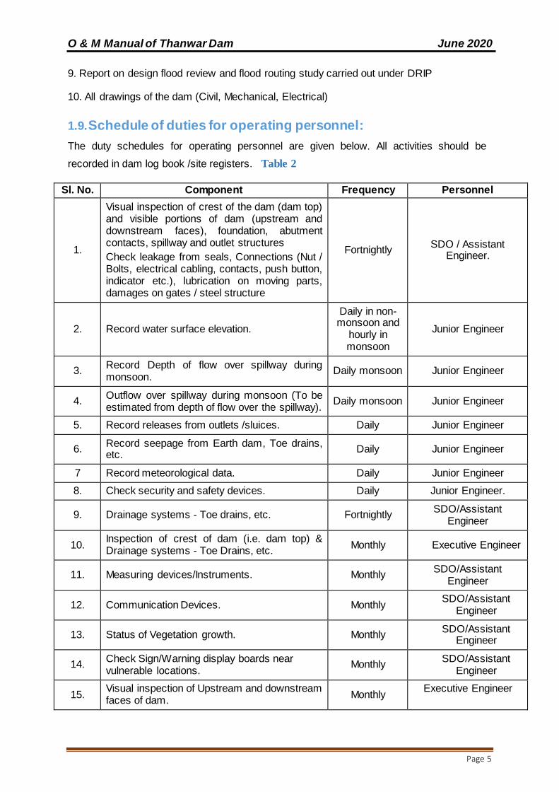
1.9.Schedule of duties for operating personnel:
The duty schedules for operating personnel are given below. All activities should be
recorded in dam log book /site registers. Table 2
Sl. No. Component Frequency Personnel
1.
Visual inspection of crest of the dam (dam top) and visible portions of dam (upstream and downstream faces), foundation, abutment contacts, spillway and outlet structures
Check leakage from seals, Connections (Nut / Bolts, electrical cabling, contacts, push button, indicator etc.), lubrication on moving parts, damages on gates / steel structure
Fortnightly SDO / Assistant
Engineer.
2. Record water surface elevation.
Daily in non-monsoon and
hourly in monsoon
Junior Engineer
3. Record Depth of flow over spillway during monsoon.
Daily monsoon Junior Engineer
4. Outflow over spillway during monsoon (To be estimated from depth of flow over the spillway).
Daily monsoon Junior Engineer
5. Record releases from outlets /sluices. Daily Junior Engineer
6. Record seepage from Earth dam, Toe drains, etc.
Daily Junior Engineer
7 Record meteorological data. Daily Junior Engineer
8. Check security and safety devices. Daily Junior Engineer.
9. Drainage systems - Toe drains, etc. Fortnightly SDO/Assistant
Engineer
10. Inspection of crest of dam (i.e. dam top) & Drainage systems - Toe Drains, etc.
Monthly Executive Engineer
11. Measuring devices/Instruments. Monthly SDO/Assistant
Engineer
12. Communication Devices. Monthly SDO/Assistant
Engineer
13. Status of Vegetation growth. Monthly SDO/Assistant
Engineer
14. Check Sign/Warning display boards near vulnerable locations.
Monthly SDO/Assistant
Engineer
15. Visual inspection of Upstream and downstream faces of dam.
Monthly Executive Engineer
O & M Manual of Thanwar Dam June 2020
Page 6
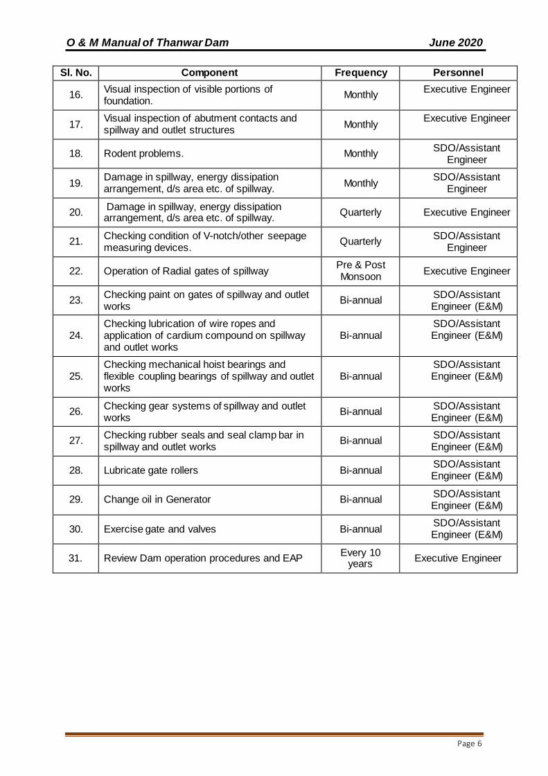
Sl. No. Component Frequency Personnel
16. Visual inspection of visible portions of foundation.
Monthly Executive Engineer
17. Visual inspection of abutment contacts and spillway and outlet structures
Monthly Executive Engineer
18. Rodent problems. Monthly SDO/Assistant
Engineer
19. Damage in spillway, energy dissipation arrangement, d/s area etc. of spillway.
Monthly SDO/Assistant
Engineer
20. Damage in spillway, energy dissipation arrangement, d/s area etc. of spillway.
Quarterly Executive Engineer
21. Checking condition of V-notch/other seepage measuring devices.
Quarterly SDO/Assistant
Engineer
22. Operation of Radial gates of spillway Pre & Post Monsoon
Executive Engineer
23. Checking paint on gates of spillway and outlet works
Bi-annual SDO/Assistant Engineer (E&M)
24. Checking lubrication of wire ropes and application of cardium compound on spillway and outlet works
Bi-annual SDO/Assistant Engineer (E&M)
25. Checking mechanical hoist bearings and flexible coupling bearings of spillway and outlet works
Bi-annual SDO/Assistant Engineer (E&M)
26. Checking gear systems of spillway and outlet works
Bi-annual SDO/Assistant Engineer (E&M)
27. Checking rubber seals and seal clamp bar in spillway and outlet works
Bi-annual SDO/Assistant Engineer (E&M)
28. Lubricate gate rollers Bi-annual SDO/Assistant Engineer (E&M)
29. Change oil in Generator Bi-annual SDO/Assistant Engineer (E&M)
30. Exercise gate and valves Bi-annual SDO/Assistant Engineer (E&M)
31. Review Dam operation procedures and EAP Every 10
years Executive Engineer
O & M Manual of Thanwar Dam June 2020
Page 7
CHAPTER 2 PROJECT OPERATION
The operation of Thanwar dam will involve regulation of its reservoir as per project
specific requirements, keeping records and ensuring public safety. Proper operating
procedures are crucial for maintaining a safe structure.
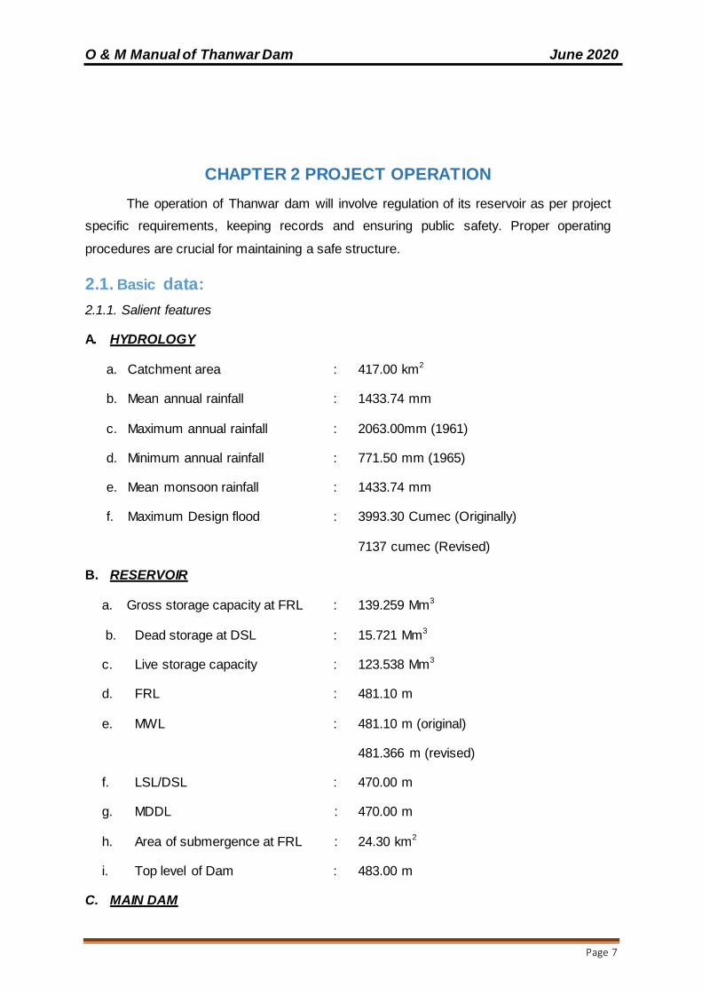
2.1. Basic data:
2.1.1. Salient features
A. HYDROLOGY
a. Catchment area : 417.00 km2
b. Mean annual rainfall : 1433.74 mm
c. Maximum annual rainfall : 2063.00mm (1961)
d. Minimum annual rainfall : 771.50 mm (1965)
e. Mean monsoon rainfall : 1433.74 mm
f. Maximum Design flood : 3993.30 Cumec (Originally)
7137 cumec (Revised)
B. RESERVOIR
a. Gross storage capacity at FRL : 139.259 Mm3
b. Dead storage at DSL : 15.721 Mm3
c. Live storage capacity : 123.538 Mm3
d. FRL : 481.10 m
e. MWL : 481.10 m (original)
481.366 m (revised)
f. LSL/DSL : 470.00 m
g. MDDL : 470.00 m
h. Area of submergence at FRL : 24.30 km2
i. Top level of Dam : 483.00 m
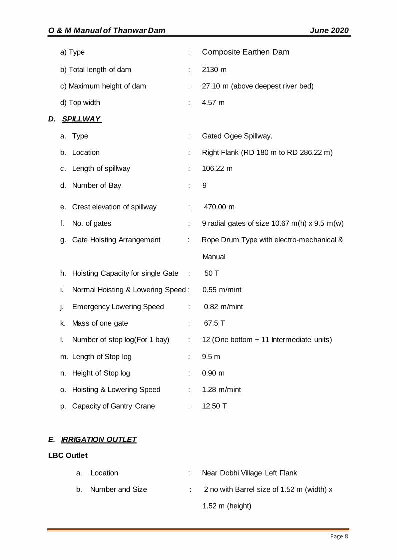
C. MAIN DAM
O & M Manual of Thanwar Dam June 2020
Page 8
a) Type : Composite Earthen Dam
b) Total length of dam : 2130 m
c) Maximum height of dam : 27.10 m (above deepest river bed)
d) Top width : 4.57 m
D. SPILLWAY
a. Type : Gated Ogee Spillway.
b. Location : Right Flank (RD 180 m to RD 286.22 m)
c. Length of spillway : 106.22 m
d. Number of Bay : 9
e. Crest elevation of spillway : 470.00 m
f. No. of gates : 9 radial gates of size 10.67 m(h) x 9.5 m(w)
g. Gate Hoisting Arrangement : Rope Drum Type with electro-mechanical &
Manual
h. Hoisting Capacity for single Gate : 50 T
i. Normal Hoisting & Lowering Speed : 0.55 m/mint
j. Emergency Lowering Speed : 0.82 m/mint
k. Mass of one gate : 67.5 T
l. Number of stop log(For 1 bay) : 12 (One bottom + 11 Intermediate units)
m. Length of Stop log : 9.5 m
n. Height of Stop log : 0.90 m
o. Hoisting & Lowering Speed : 1.28 m/mint
p. Capacity of Gantry Crane : 12.50 T
E. IRRIGATION OUTLET
LBC Outlet
a. Location : Near Dobhi Village Left Flank
b. Number and Size : 2 no with Barrel size of 1.52 m (width) x
1.52 m (height)

O & M Manual of Thanwar Dam June 2020
Page 9
c. Invert level : 470.00 m
d. Outlet Discharge : 10.19 cumec
F. GATES & HOISTS OF IRRIGATION
LBC Outlet
a. size : 2 no gate with size of 1.52 m (width) x
1.52 m (height)
b. Sill Level : 470.00 m
c. Operation arrangement : Manually (Rope-Drum Type)
d. Capacity of Hoist : 20 T
e. Maximum vertical lift of the gate : 1.5 m
f. Type of gate : Wheeled type
G. DISTRIBUTION SYSTEM
a. Gross command area : 14500 ha
b. Cultivable command area : 11605 ha
c. Area irrigated during kharif : 8884 ha
d. Area irrigated during Rabi : 7552 ha
e. Total Annual irrigation : 18211 ha
f. Total length of distribution system,
Main canal : LBC 48.00 km
Distributary : LBC 88.67 km
Minors : LBC 100.77 km
Sub-minor : LBC 42.23 km
g. Sill level of head regulator : LBC 470.00 m
h. Bed width of canal at head : LBC 6.705 m
i. Bed level of canal at head : LBC 470.00 m
2.1.2. Area capacity curve.
A drawing showing area-capacity curves of Thanwar dam is at Appendix-IV
In tabular form it is given as under Table 3

O & M Manual of Thanwar Dam June 2020
Page 10
RL (m)
Area (Msqm)
Capacity (MCM)
Remark
470 4.4 15.721 LSL
471 4.48 21.249
472 5.5 27.491
472.2 5.7 29.141
473 5.8 34.741
474 8.29 44.241
475 9.7 54.499
476 11 63.987
477 12.5 74.747
478 14 91.624
479 15.8 104.312
480 17.5 116.996
481.1 24.3 139.259 FRL
2.1.3. Data of Historic floods
The project was completed during the year 1984. The spillway outflow during flood period
in Thanwar dam is given below in tabular format.
Table 4
S.
No. Year Date
Outflow Discharge
over Spillway (cusec)
Outflow Discharge
over Spillway (cumec)
1 1993-94 09-09-1993 13899.00 393.58
2 1994-95 17-07-1994 55383.00 1568.27
3 1995-96 29-07-1995 5813.00 164.61
4 1996-97 18-08-1996 8755.00 247.91
5 1997-98 06-08-1997 10741.00 304.15
6 1998-99 15-08-1998 7572.00 214.42
7 1999-00 17-09-1999 69680.00 1973.12
8 2002-03 08-09-2002 3036.00 85.97
9 2003-04 10-09-2003 3914.53 110.85
10 2004-05 22-08-2004 18605.86 526.86
11 2005-06 14-09-2005 34916.00 988.71

O & M Manual of Thanwar Dam June 2020
Page 11
12 2006-07 14-08-2006 12614.00 357.19
13 2008-09 12-08-2008 2880.00 81.55
14 2010-11 08-09-2010 7799.00 220.84
15 2011-12 14-09-2011 22156.00 627.39
16 2012-13 06-08-2012 8595.00 243.38
17 2013-14 18-08-2013 48025.00 1359.92
18 2014-15 12-09-2014 4054.00 114.80
19 2016-17 08-07-2016 39723.00 1124.83
20 2019-20 08-09-2019 55670.76 1576.42
2.1.4. Latest Design Inflow Flood and Flood Routing Studies:
In terms of the Indian Standard IS 11223:1985 classification criteria, Thanwar Dam is
classified as an “Large Dam” and, therefore, qualifies for PMF (Probable Maximum
Flood) as the design flood. The originally Design Flood for the dam is 3993.30 cumec. The
design flood studies submitted to CWC and PMF examined for the project by the Hydrology
(DSR) Directorate, CWC is 7137 cumec. Flood routing studies were carried out by the
State DSO. The maximum routed outflow comes out to be 6502 cumec and the MWL
reaches EI. 481.366 m, this is 1.634 m below than the TBL (453.28 m) and project was
designed is found to be safe and there is no need of revision.
2.2. Operation Plan:
The operation of the dam includes observation of reservoir levels, keeping records
and ensuring both dam and public safety. This Manual covers the normal operation
procedures to be followed during both monsoon and non-monsoon. Special operational
procedures are to be followed during an emergency situation as per the Emergency Action
Plan.
Proper communication and information is provided for the downstream inhabitants
regarding discharge of flood water through the spillway when there is a forecast of heavy
rain fall in catchment areas.
Mock drills and exercising of the service gates of the head regulator is carried out
before every crop season.
All the gates and hoists of the head regulator are inspected and their parts
lubricated and repaired as necessary before operation.
The O & M Manuals of the Gates Manufacturer’s would however govern the overall
maintenance of Gates & Hoists whenever there is any contradiction with the instructions
given in the Manual.
O & M Manual of Thanwar Dam June 2020
Page 12
2.3 Normal Operation Procedures:
2.3.1. Rule Curve/Reservoir Operations.
Thanwar dam has gated spillway with 9 radial gates of size 10.67 m (h) x 9.5 m (w).
Presently there is no rule curve available. The reservoir generally starts to fill from RL
470.00 m (MDDL) in the 2nd week of June to RL 481.10 m (FRL) and it is maintained at
same level till end of October. Then it slowly starts to deplete as per irrigation requirement
taking into consideration the reservoir position.
During normal period, various observations such as reservoir water level, tail water
level, general behavior of dam, seepage, gallery seepage and pressures, observation of
dam temperature and deflection of dam are recorded throughout the year. The dam and
reservoir is closely watched round the clock during the rainy season.
The reading of tank gauge is taken daily at 8.00 a.m. by the gauge reader during
normal period and hourly during rainy season.
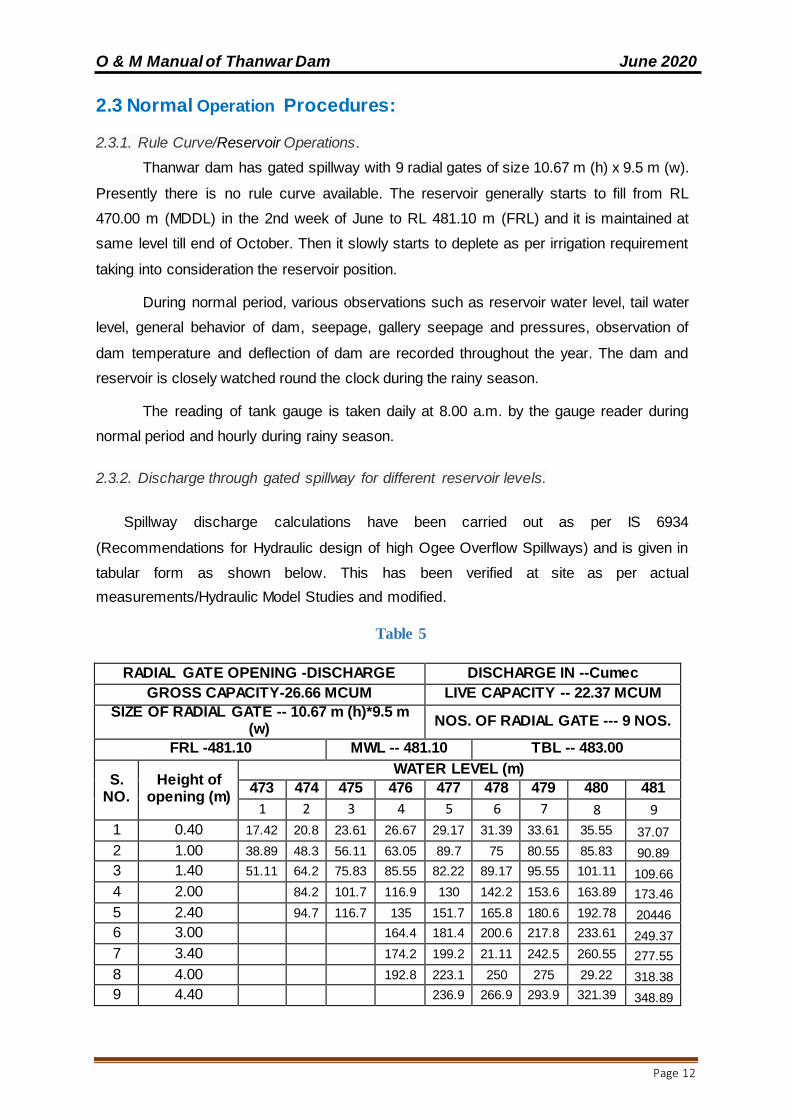
2.3.2. Discharge through gated spillway for different reservoir levels.
Spillway discharge calculations have been carried out as per IS 6934
(Recommendations for Hydraulic design of high Ogee Overflow Spillways) and is given in
tabular form as shown below. This has been verified at site as per actual
measurements/Hydraulic Model Studies and modified.
Table 5
RADIAL GATE OPENING -DISCHARGE DISCHARGE IN --Cumec
GROSS CAPACITY-26.66 MCUM LIVE CAPACITY -- 22.37 MCUM
SIZE OF RADIAL GATE -- 10.67 m (h)*9.5 m (w)
NOS. OF RADIAL GATE --- 9 NOS.
FRL -481.10 MWL -- 481.10 TBL -- 483.00
S. NO.
Height of opening (m)
WATER LEVEL (m)
473 474 475 476 477 478 479 480 481
1 2 3 4 5 6 7 8 9
1 0.40 17.42 20.8 23.61 26.67 29.17 31.39 33.61 35.55 37.07
2 1.00 38.89 48.3 56.11 63.05 89.7 75 80.55 85.83 90.89
3 1.40 51.11 64.2 75.83 85.55 82.22 89.17 95.55 101.11 109.66
4 2.00 84.2 101.7 116.9 130 142.2 153.6 163.89 173.46
5 2.40 94.7 116.7 135 151.7 165.8 180.6 192.78 20446
6 3.00 164.4 181.4 200.6 217.8 233.61 249.37
7 3.40 174.2 199.2 21.11 242.5 260.55 277.55
8 4.00 192.8 223.1 250 275 29.22 318.38
9 4.40 236.9 266.9 293.9 321.39 348.89
O & M Manual of Thanwar Dam June 2020
Page 13
10 5.00 289.2 321.9 352.5 383.07
11 5.40 304.4 340.3 371.94 403.6
12 6.00 360.8 399.44 438.32
13 6.40 375.6 416.39 458.03
14 7.00 438.61 475.21
15 7.40 492.49
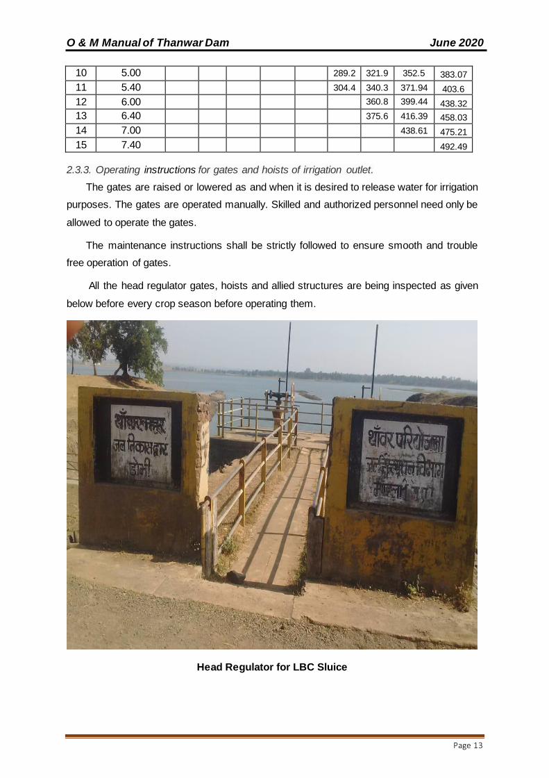
2.3.3. Operating instructions for gates and hoists of irrigation outlet.
The gates are raised or lowered as and when it is desired to release water for irrigation
purposes. The gates are operated manually. Skilled and authorized personnel need only be
allowed to operate the gates.
The maintenance instructions shall be strictly followed to ensure smooth and trouble
free operation of gates.
All the head regulator gates, hoists and allied structures are being inspected as given
below before every crop season before operating them.
Head Regulator for LBC Sluice
O & M Manual of Thanwar Dam June 2020
Page 14
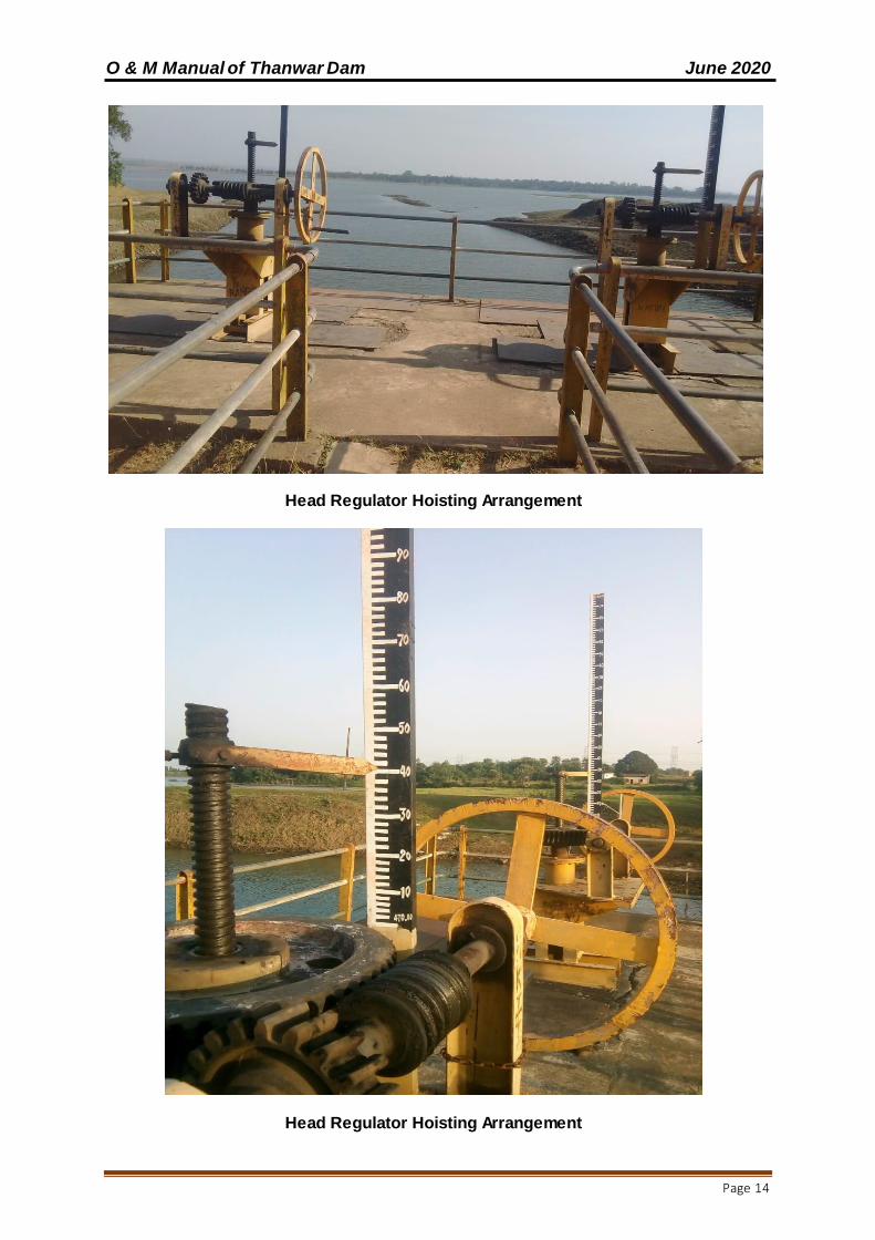
Head Regulator Hoisting Arrangement
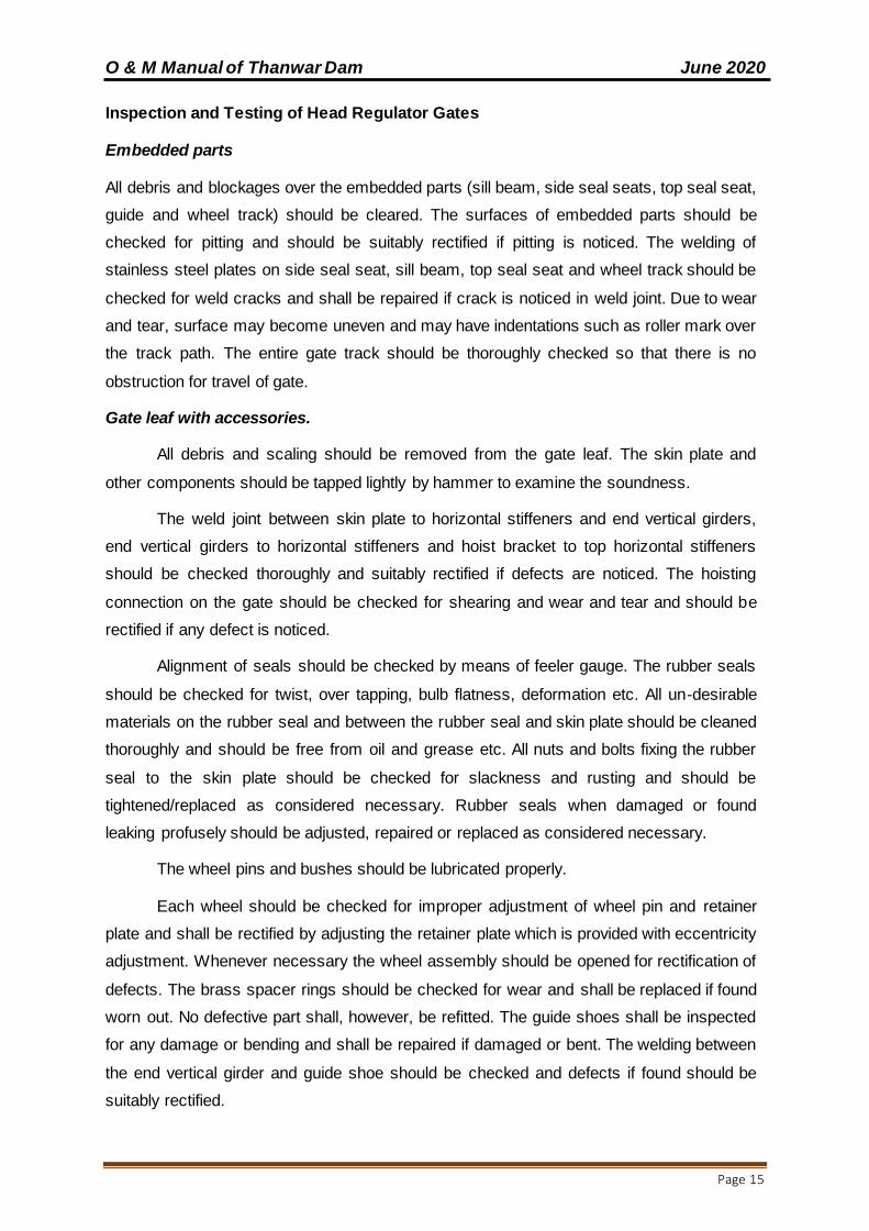
Head Regulator Hoisting Arrangement
O & M Manual of Thanwar Dam June 2020
Page 15
Inspection and Testing of Head Regulator Gates
Embedded parts
All debris and blockages over the embedded parts (sill beam, side seal seats, top seal seat,
guide and wheel track) should be cleared. The surfaces of embedded parts should be
checked for pitting and should be suitably rectified if pitting is noticed. The welding of
stainless steel plates on side seal seat, sill beam, top seal seat and wheel track should be
checked for weld cracks and shall be repaired if crack is noticed in weld joint. Due to wear
and tear, surface may become uneven and may have indentations such as roller mark over
the track path. The entire gate track should be thoroughly checked so that there is no
obstruction for travel of gate.
Gate leaf with accessories.
All debris and scaling should be removed from the gate leaf. The skin plate and
other components should be tapped lightly by hammer to examine the soundness.
The weld joint between skin plate to horizontal stiffeners and end vertical girders,
end vertical girders to horizontal stiffeners and hoist bracket to top horizontal stiffeners
should be checked thoroughly and suitably rectified if defects are noticed. The hoisting
connection on the gate should be checked for shearing and wear and tear and should be
rectified if any defect is noticed.
Alignment of seals should be checked by means of feeler gauge. The rubber seals
should be checked for twist, over tapping, bulb flatness, deformation etc. All un-desirable
materials on the rubber seal and between the rubber seal and skin plate should be cleaned
thoroughly and should be free from oil and grease etc. All nuts and bolts fixing the rubber
seal to the skin plate should be checked for slackness and rusting and should be
tightened/replaced as considered necessary. Rubber seals when damaged or found
leaking profusely should be adjusted, repaired or replaced as considered necessary.
The wheel pins and bushes should be lubricated properly.
Each wheel should be checked for improper adjustment of wheel pin and retainer
plate and shall be rectified by adjusting the retainer plate which is provided with eccentricity
adjustment. Whenever necessary the wheel assembly should be opened for rectification of
defects. The brass spacer rings should be checked for wear and shall be replaced if found
worn out. No defective part shall, however, be refitted. The guide shoes shall be inspected
for any damage or bending and shall be repaired if damaged or bent. The welding between
the end vertical girder and guide shoe should be checked and defects if found should be
suitably rectified.
O & M Manual of Thanwar Dam June 2020
Page 16
The hoist pin should be lubricated. All nuts, bolts and screws etc. should be
checked for slackness and should be tightened if necessary. The wheel assemblies should
be adjusted by the eccentric arrangement provided in retainer plates to ensure that all
wheels bear uniformly on wheel tracks, particularly in closed position of gates.
Restraining Arrangements.
The welding of eye piece and flanges to the stems should be checked thoroughly
and defects, if noticed, shall be rectified suitably. The split bushes and the stems should be
lubricated properly. All bolts and nuts should be checked for slackness and shall be
tightened if necessary. The defective Bolts, nuts and screws etc. should be replaced. The
stem nuts should be checked for straightness and shall be rectified if found bent. The screw
rod and the intermediate stems should be checked for binding and rectified it found bent.
Testing.
1) The gate should be tested for smooth travel throughout the groove without appreciable
swing. All wheels shall always be in contact with the wheel track face during the entire
travel.
2) The gate should neither be subjected to under pressure nor any extra effort be
needed to operate the gate in no load condition.
3) There should not be undue vibration in the gate and structure during its travel while
on load. If undue vibrations are noticed the reasons should be investigated and the
reservoir level at which this occurs should be recorded. The gate shall not be kept in
the position where vibration is noticed until remedial measures are taken.
4) In closed position, the gate should be watched against any leakage under maximum
head condition during the year.
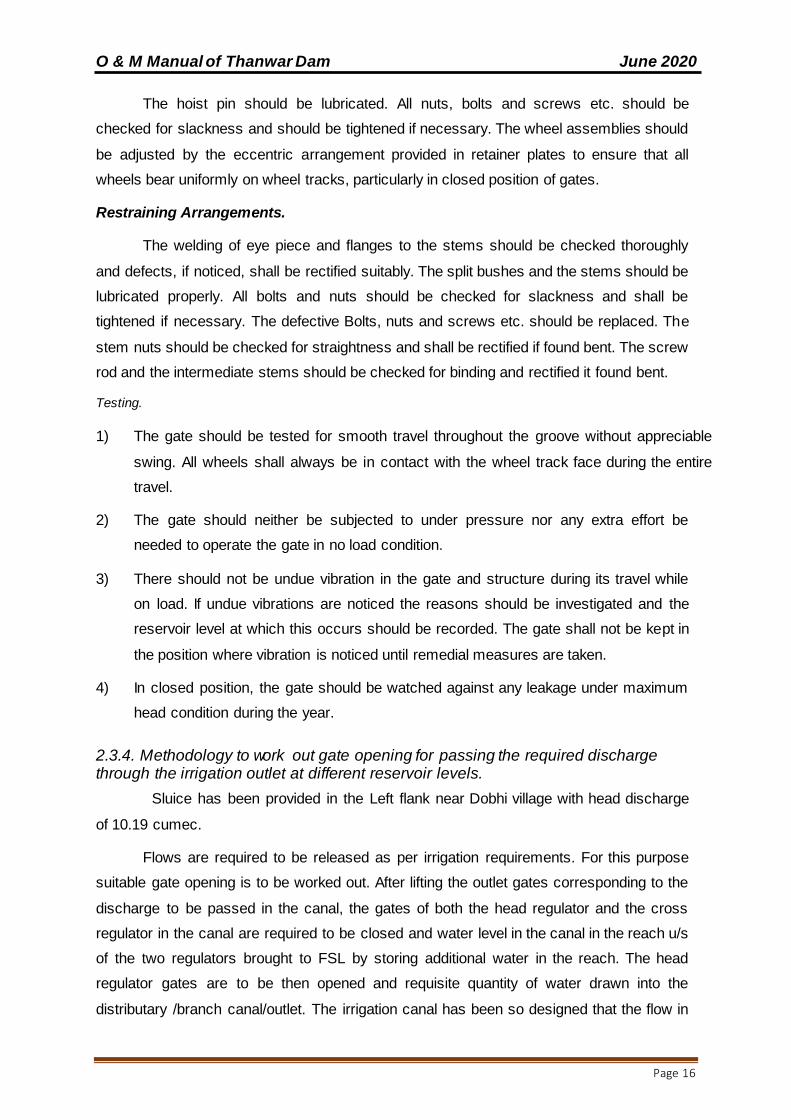
2.3.4. Methodology to work out gate opening for passing the required discharge through the irrigation outlet at different reservoir levels.
Sluice has been provided in the Left flank near Dobhi village with head discharge
of 10.19 cumec.
Flows are required to be released as per irrigation requirements. For this purpose
suitable gate opening is to be worked out. After lifting the outlet gates corresponding to the
discharge to be passed in the canal, the gates of both the head regulator and the cross
regulator in the canal are required to be closed and water level in the canal in the reach u/s
of the two regulators brought to FSL by storing additional water in the reach. The head
regulator gates are to be then opened and requisite quantity of water drawn into the
distributary /branch canal/outlet. The irrigation canal has been so designed that the flow in

O & M Manual of Thanwar Dam June 2020
Page 17
the system is to be maintained at FSL all the time during supply. Depending upon
requirement the flow through these outlets are controlled to optimize the use.
The shutter in head regulator is operated by rotational method. The flow into the
canal system depends upon the Reservoir water level and gate opening.
Approach Channel of Left Bank Main Canal
Left Bank Main Canal Sluice
O & M Manual of Thanwar Dam June 2020
Page 18
Left Bank Main Canal at Head
2.3.5. Safety Aspects:
The safety and security of dam against the structural damages by vandals, public
and unauthorized operation of outlet gates is of paramount importance. The Division has
formed the water users’ association among the cultivators. The combined effort of the both
dam authorities and water users’ association ensures proper O & M of the irrigation outlet.
The water users’ association is imparted capacity building training in this regard from time
to time by WALMI, Govt. of Madhya Pradesh.
2.4. Emergency Operation:
The emergency operation will be carried out following the Emergency Action Pan
(EAP). The emergency conditions are outlined in Chapter 4 under clause 4.2.1 on
Immediate Maintenance. The EAP together with this Manual will be present at site at all
times.
2.5. Reservoir Capacities:
The reservoir capacity may reduce with time because of reservoir sedimentation.
Bathymetric survey on a periodic basis is to be considered after every 10 years.
2.6. Record Keeping: Following records of reservoir operations are being maintained:

O & M Manual of Thanwar Dam June 2020
Page 19
1. Rainfall record on daily basis throughout the year.
2. Reservoir levels on daily basis during non-monsoon and hourly basis during
monsoon.
3. Depth of outflow over the spillway on hourly basis during monsoon.
4. Estimated spillway outflows during monsoon on hourly basis.
5. Irrigation releases.
6. Water audit register to be maintained for estimating the inflows on hourly basis
during monsoon and daily basis during non-monsoon by accounting all the
releases/outflows and the incremental change in storage in the reservoir.
7. All operating procedures

O & M Manual of Thanwar Dam June 2020
Page 20
This page is left blank intentionally
O & M Manual of Thanwar Dam June 2020
Page 21
CHAPTER 3.PROJECT INSPECTION
An effective inspection programme is essential for identifying problems and
providing safe performance of the dam.
The current practice of Inspection is adopted as per Madhya Pradesh Water
Resources Department, Operation and Maintenance series technical circular no. 3,
“August 2015, Periodical (Bi-annual) Inspection of Dams (Head Works)”.
3.1. Objective of Dam inspection:
The main purpose of dam safety inspections is to determine whether the structural
and operational aspects of the dam and its component parts are functioning safely in
accordance with the design and established standard/ acceptable practices. It helps to
identify deficiencies or concerns that potentially affect the safety of the dam and to take
corrective actions to remedy those deficiencies before serious consequences develop.
Detailed description on project inspections is available in the Guideline for Safety
Inspection of dams (DocNo.CDSO_GUD_DS_07_ v1.0), CWC 2018
(https://damsafety.in/ecm includes/PDFs/Guidelines_for_Safety_Inspection_of_Dams.pdf).
However an overview of the various types of inspections to be carried out in Thanwar dam
is given below. Note that for uploading Inspection Data into DHARMA, the Inspection
Instructions & Forms given in the aforementioned Guideline for Safety Inspection of Dams
should be used.(see Appendix-I)
3.2. Types of Dam Safety Inspections:
The type of inspection to be conducted will depend on the purpose of the inspection.
Dam safety inspections are conducted to determine the status of a dam and its features
relative to its structural and operational safety.
Four types of dam safety inspections are to be carried out. They are:
1) Informal inspections
2) Scheduled inspections
3) Special (unscheduled) inspections
4) Comprehensive evaluation inspections.
3.2.1. Informal Inspections
The informal inspections are performed by the Engineer-in-charge of the dam and
his staff while carrying out their regular duties. Informal inspections assist in a continuous
surveillance of the dam which is critical to proper operation and maintenance of the dam.

O & M Manual of Thanwar Dam June 2020
Page 22
They consist of frequent inspections for observing the general issues/problems and
functioning of the dam and appurtenant structures. The informal inspections are important
and performed at every available opportunity. The informal inspections are not as detailed
as comprehensive, scheduled, and special inspections. They require that a formal report
be submitted to the dam authorities only if a condition is detected that might endanger the
dam.
3.2.2. Scheduled Inspections:
Scheduled inspections are performed to gather information on the current condition
of the dam and its appurtenant works. The scheduled inspections consist of pre-monsoon
and post monsoon inspections and other scheduled inspections. The Pre- & Post monsoon
inspections are conducted by field engineers every year as per the inspection schedule
below.
The deficiencies, thus noticed, and shall be endorsed to State Dam Safety
Organization for scrutiny and suggestion for possible remedial measures.
Table 6 Inspection Schedules
Type of Inspection
Last date for
Completion of inspection Sending inspection reports to SDSO
Pre- monsoon 15th May 15th June
Post-monsoon 15th November 31st December
(Note – To be conducted by Executive Engineer, Water resources Division Mandla and
Superintending Engineer, Water Resources Circle, Jabalpur)
Other scheduled inspections are conducted at least once in every 3 years by the engineers
of State DSO along with Geologist and representative of Mechanical Wing.
All scheduled inspections are to be carried out as per the Guideline for Safety Inspection of
dams (Doc No. CDSO_GUD_DS_07_ v1.0), CWC 2018 (https://damsafety.in/ecm-
includes/PDFs/Guidelines_for_Safety_Inspection_of_Dams.pdf).These inspections will
include the following components as a minimum:
1. Review of the past inspection reports, Monitoring data & photographs, Maintenance
records and other pertinent data.
2. Inspection of the dam and its appurtenant works.
3. Preparation of a report with relevant documentation and photographs.

O & M Manual of Thanwar Dam June 2020
Page 23
3.2.3. Special (Unscheduled) Inspections:
Special inspections are performed to resolve specific problems of the dam. This is
performed by an Independent Expert Panel or Dam Authorities. Special inspections are not
regularly scheduled activities but are usually made before or immediately after the dam or
appurtenant works have been subjected to unusual events or conditions, such as an
unusually high flood or a significant earthquake.
Japan Water Agency (JWA) has developed an excellent system of carrying out
inspections after an earthquake event. For details refer “Inspection Manual for Dam Field
Engineers after Seismic Events, Ichari Dam, Uttarakhand (CDSO_GUD_DS_0_v1.0,
September2017). The manual is available at the followinglink:https://damsafety.in/ecm-
includes/PDFs/Inspection_Manual_for_Dam_Field_Engineers_After_Seismic_Events.pdf.
3.2.4 Comprehensive Evaluation Inspections:
For comprehensive dam safety evaluation an independent panel of experts known
as Dam Safety Review Panel (DSRP), is to be set up by the MPWRD which shall consist
of experts from the fields of Geology, Hydrology, Designs, and Construction for
determining the condition of dam and appurtenant works. The main objective of the DSRP
is to carry out an independent expert review of the overall health status of the dam and to
propose remedial action, prior to the initiation of rehabilitation activities. The panel would
undertake the evaluation of the dam once in 10years or after occurrence of any extreme
events, if required. The State Dam Safety Organization arranges the meetings and site
visits of DSRP.
Terms of Reference (TOR) of comprehensive dam safety evaluation shall include
but will not to be limited to:
1. General assessment of hydrologic and hydraulic conditions, review of design flood,
flood routing for revised design flood and mitigation measures.
2. Review and analysis of available data of dam design, construction, operation
maintenance and performance of dam structure and appurtenant works.
3. A visual inspection or field examination of the dam, its appurtenant works, and the
surrounding areas.
4. Review of the instrumentation records and structural behavior reports, if any.
5. Evaluation of procedures for operation, maintenance and inspection of dam and to
suggest improvements / modifications.
6. Evaluation of any possible hazardous threat to the dam structure such as dam
abutment slope stability failure or slope failures along the reservoir periphery.
O & M Manual of Thanwar Dam June 2020
Page 24
3.2.4.1. Details to be provided to DSRP before inspection:
All relevant details / data / drawings for the dam project to be examined by the
DSRP shall be provided at least 3 months in advance of the proposed visit.
This will include:-
a) General Information
1. Scope of project
2. Basic data and salient features
3. Issues related to safety of dam including any earlier dam safety related incidents
4. Emergency preparedness – Communications, Auxiliary power, Downstream
Warning system and security at site.
b) Hydrology
1. Description of drainage basin
2. Original inflow design flood, MWL and routed outflow
3. Revised design flood and flood routing study carried out by the project authorities
and approved by CWC.
4. Area – Capacity curves.
c) Geology
1. Dam site geology including geological reports.
2. Any Special problems and their treatment.
3. Reservoir competency as per geological report.
4. Slope stability issues along reservoir rim.
d) Drawings of the dam and HM works
1. Layout plan
2. Upstream & Downstream Elevation.
3. Cross – Sections of the Dam and Spillway
4. Foundation treatment details
5. Junction between Earthen embankment & Concrete/Masonry abutment of spillway.
6. Irrigation Outlet details
7. Layout details of Gates and Hoists of Irrigation outlet
8. Instrumentation details
e) Dam and Spillway
1. Geological reports
2. Special problems encountered, if any.

O & M Manual of Thanwar Dam June 2020
Page 25
3. Foundation treatment including treatment of faults / shear zones / weak zones,
curtain / consolidation grouting, drainage provisions, any other special treatment,
cut-off trench, etc.
4. Design criteria and result of stability analysis
5. Adequacy of design – from dam safety considerations
6. Hydraulic design of Spillway
7. Pre-construction material testing reports including adequacy of field and laboratory
investigations, appropriateness of materials selected etc.
8. Post-construction testing reports, if any,
3.2.4.2. Field Inspection – Observation & Recommendations regarding Remedial Measures:
Each component of the project is inspected; evaluated and specific problems are to be
brought out. Recommendations for necessary remedial measures need to be included in
the panel’s report.
Various project components to be inspected include:
a) Dam
1. Upstream face
2. Downstream face
3. Top of dam
4. Structural behaviour as observed visually and as per evaluation of instrumentation
data (any visible cracking, deflections etc.)
5. Seepage assessment
6. Condition of natural / excavated slopes in the abutments, both on u/s and d/s of the
dam.
7. Any specific problems / deficiencies.
b) Surplus Escape (Spillway)
1. Civil structure
2. Spill channel, drop structures etc.
3. Downstream safe carrying capacity of river / channel
c) River / Canal Outlets
1. Civil structures
2. Conduits / outlets through Embankment dam.
d) Flood Hydrology
1. Extent & Sufficiency of data available

O & M Manual of Thanwar Dam June 2020
Page 26
2. Method used for estimating the design flood.
3. Design flood review study.
4. Flood routing studies with the revised flood.
5. Adequacy of free board available.
f) Miscellaneous services / facilities
1. Access Roads
2. Communication facilities (Telephone, Mobile etc.)
3.2.4.3. Components Involved
A comprehensive evaluation inspection of a dam typically consists of five components:
1. Project records review (i.e. study of all design / construction records / drawings,
history of the dam’s performance, past inspection notes / reports, notes on distress
observed etc.).
2. Inspection of the dam and its appurtenant works.
3. Preparation of a detailed report of the inspection.
4. Education and training of the dam engineers on the issues observed during dam
inspection, identification of potential dam failure modes & to carryout additional
field investigations & laboratory testing as required. Dam engineers should be
made part of the inspection process so that they take ownership and are committed
to implementing the recommended remedial measures.
5. Design studies e.g. review of design flood, checking of the adequacy of spillway
capacity, freeboard requirements, dam stability, any special study as required &
submission of the report.
O & M Manual of Thanwar Dam June 2020
Page 27
CHAPTER 4 PROJECT MAINTENANCE
A good maintenance program will protect a dam against deterioration, prolong its life,
and greatly reduce the chance of failure. The dam authorities and operating and main-
tenance personnel must be aware of the potential problems which can lead to failure of a
dam. Nearly all the components of a dam and its materials are susceptible to damage and
deterioration if not well maintained.
This Manual is to be referred to mainly for routine maintenance works.
The designs, drawings and technical specifications for most of the condition based
and immediate maintenance works will need to be provided by the State DSO/Designs
offices. Guidance of experienced engineers/panel of experts will need to be taken.
4.1. Maintenance Plan:
Timely maintenance assures that a dam and reservoir would remain in a good working
condition and prevents more harmful conditions from developing.
4.2. Maintenance Priorities:
Maintenance activities need to be prioritized.
4.2.1. Immediate Maintenance
The following conditions are critical and require immediate action by Dam authorities.
Evidence of excessive seepage through the Earth dam, exiting on its
downstream face or anywhere on the downstream of the dam and increasing in
volume.
Earth Dam showing signs of piping or internal erosion indicated by increasingly
cloudy seepage or other symptoms.
An increase in the reservoir level to near the top of the dam.
Water overtopping the earthen dam.
An Earth dam about to be breached by erosion, slope failure etc.
An EAP is to be activated when any of the above conditions are noted.
4.2.2. Condition based maintenance
The following maintenance works are undertaken as soon as possible after the defective
condition is noted which may include:
Removal of all vegetation and bushes from the dam and restoring any eroded
areas and to establish good grass cover.

O & M Manual of Thanwar Dam June 2020
Page 28
Fill animal burrows.
Repair livestock trails and fences to keep livestock off dam.
Restore and reseed eroded areas and gullies on embankment dams.
Repairs of any cracks in earth dam.
Cleaning and repair of drains.
Repair of defective gates and other hydro-mechanical equipment.
Repair any concrete or metal components that have deteriorated.
Repair for any damages on the spillway including its glacis, piers, training
walls/abutments, energy dissipaters, downstream fall structures, spill channel
etc.
4.2.3. Routine Maintenance
Following tasks are performed on a continuous basis. These include:
To measure flow rate of seepage and turbidity from Earth dam.
Maintain turfing on d/s slope of Earth dam.
Repair any gullies formation in Earth dam
Clean the surface drains on the downstream slope of Earth dam
Remove silt from the d/s toe drain and outfall drains of Earth dam.
Rodent damage: Remove or destroy the rodents and fill any burrow holes
immediately.
Upstream slope riprap: Repair the upstream riprap disturbed due to high water or
wave action.
Noxious weeds: Remove any noxious weeds on and around the dam embankment,
reservoir, and spillways.
Remove any vegetation growing on the earth dam and spillway.
Ensure approach road to the dam to be in good condition.
Test the communication equipment.
Checking the operation of instruments in the dam.
Servicing and lubrication of gates of Head Regulator,
Keeping the gate slots clear of silt/debris.
4.3. Procedures for undertaking routine Maintenance works:
4.3.1. Earth work in earthen dam
The surfaces of an earthen dam may deteriorate due to several reasons. For
example, wave action may cut into the upstream slope, vehicles may cause ruts in the crest
or slopes, trails left by livestock can result in erosion, or runoff waters may leave erosion
O & M Manual of Thanwar Dam June 2020
Page 29
gullies on the downstream slope. Other special problems, such as shrinkage cracks or
rodent damage, may also occur. Damage of this nature must be repaired constantly.
The maintenance procedures to be described in the O&M Manual will be used for
repairs of routine earthwork problems. However, this section is not intended to be a technical
guide, and the methods discussed should not be used to solve serious problems. Conditions
such as embankment slides, structural cracking, and sinkholes threaten the immediate
safety of a dam and require immediate repair under the directions of experienced
engineers/Expert panels.
The material selected for repairing embankments should be free from vegetation,
organic materials, trash, and large rocks.
If flow-resistant portions of an embankment (such as impervious core) are being
repaired, materials that are high in clay or silt content should be used. If the area is to be
free draining or highly permeable (such as pervious shell of an embankment dam) the
material should have a higher percentage of sand and gravel. It is usually satisfactory to
replace or repair damaged areas with soils like those originally in place.
An important soil property affecting compaction is moisture content. Soils that are too
dry or too wet do not compact well. One may test repair material by squeezing it into a tight
ball. If the sample keeps its shape without cracking and falling apart (which means it is too
dry), and without depositing excess water onto the hand (which means it is too wet), the
moisture content is near the proper level.
Before placement of earth, the repair area needs to be prepared by removing all
inappropriate material. All vegetation, such as bushes, roots, and tree stumps, along with
any large rocks or trash need to be removed. Also, unsuitable earth, such as organic or
loose soils, should be removed, so that the work surface consists of exposed, firm, clean
embankment material.
Following cleanup, shape and dress the affected area so that the new fill can be
compacted to the level specified in the technical specifications. Also it should properly key
with the existing fill for which benches of suitable dimensions need to be made in the
existing fill. Further trim the slopes and roughen the surfaces by scarifying or plowing to
improve the bond between the new and existing fill and to provide a good base to compact
against.
Place soils in loose layers up to 20 centimeters thick and compact manually with
pneumatic tampers or mechanically to form a dense mass free from large rock or organic
O & M Manual of Thanwar Dam June 2020
Page 30
material. Keep soil moisture in the proper range. The fill should be watered and mixed to the
proper wetness and allowed to dry if too wet.
Erosion is one of the most common maintenance problems in embankment
structures. Erosion is a natural process and its continuous forces will eventually wear down
almost any surface or structure. Periodic and prompt maintenance is essential to prevent
continuous deterioration and possible failure.
Turfing, free from weeds and bushes, is an effective means of preventing erosion.
Rills and gullies should be filled with suitable soil, compacted, and then seeded for
growing the turfing. Erosion in large gullies can be slowed by stacking bales of hay or straw
across the gully until permanent repairs can be made.
Paths due to pedestrian, livestock, or vehicular traffic (two and four-wheeled) are a
problem on many embankments. If a path has become established, vegetation will not
provide adequate protection and more durable cover will be required unless traffic is
eliminated. Stones may be used effectively to cover such footpaths.
In addition, steps can be provided/ constructed at regular intervals along the length of
the dam for going from downstream toe to the dam top. All vehicular traffic, except for
maintenance, should be restricted from the dam.
Erosion is also common at the point where an embankment and the concrete walls of
a spillway or other structure meet. Poor compaction adjacent to such walls during
construction and later settlement can result in an area along the wall that is lower than the
grade of the embankment.
Runoff, therefore, often concentrates along these structures, resulting in erosion.
People also often walk along these walls, wearing down the vegetative cover. Workable
solutions include re-grading the area so that its slopes away from the wall, adding more
resistant surface protection, or constructing steps.
4.3.2. Upstream Riprap
The upstream face of a dam is required to be protected against wave erosion. Rip-rap is
normally provided for the purpose with filter layers below.
Nonetheless, erosion can still occur in existing riprap. Water running down the slope under
the riprap can erode the embankment. Sections of riprap that have slumped downward are
often signs of this kind of erosion.
Effective slope protection must prevent soil from being removed from the embankment.
O & M Manual of Thanwar Dam June 2020
Page 31
When erosion occurs on the upstream slope of a dam, repairs should be made as soon as
possible. Repairs can be made following the same design details as provided in the
embankment dam. Proper preparation of surface of the existing embankment as described
in the earlier para including cutting benches as per site conditions for better bonding is
necessary. IS 8237- Code of practice for protection of Slopes for Reservoir Embankments
may also be referred too.
4.3.3. Controlling Vegetation
Keep the entire dam clear of unwanted vegetation such as bushes or trees. Excessive
growth may cause several problems such as:
It can obscure the surface of an embankment and not allow a proper inspection of
the dam.
Large trees can be uprooted by high wind or erosion and leave large holes that can
lead to breaching of the dam.
Some root systems can decay and rot, creating passageways for water, and thus
causing erosion.
Growing root systems can lift concrete slabs or structures.
Rodent habitats can develop.
All bushes/trees should be as far as possible removed by roots. The resulting holes
should be filled with well compacted earth. It would be desirable to remove the
plants/vegetation at their early stage to prevent their growing into big tree/bushes. In cases
where trees and bushes cannot be removed, the root systems should be treated with
herbicide (properly selected and applied) to retard further growth. Use of harmful chemicals
should be avoided. Concerned Government Agencies should be consulted for selection of
appropriate herbicides & their use for control of vegetation on dam structures.
Further, it is desirable that there are no trees or bushes within 500 m of the toe drain
on the downstream side of the dam.
4.3.4. Controlling Animal Damage
Livestock should not be allowed to graze on an embankment surface. When soil is
wet, livestock can damage vegetation and disrupt the uniformity of the surface. Moreover,
livestock tend to walk in established paths and thus can promote erosion. Such paths should
be re-graded and seeded, and the livestock permanently fenced out of the area.
The burrows and tunnels of burrowing animals (beaver, muskrat, groundhogs and
others) weaken earthen embankments and serve as pathways for seepage from the

O & M Manual of Thanwar Dam June 2020
Page 32
reservoir. Large burrows on an embankment should be filled by mud packing. This method
involves placing vent pipe in a vertical position over the entrance of the den. Making sure
that the pipe connection to the den does not leak, the mud-pack mixture is poured into the
pipe until the burrow and pipe are filled with the soil-water mixture. The pipe is removed and
more dry earth is tamped into the entrance. As per some US publications, the mud pack is
generally made by adding water to 90% earth & 10% cement mixture until a slurry or thin
cement consistency is attained. For bigger holes, bentonite coated stones can also be used.
All entrances should be plugged with well-compacted earth & vegetation re-established.
Dens should be eliminated without delay. Different repair measures will be necessary if a
dam has been damaged by extensive small rodent tunneling or large rodent activity. The
area around the entrance can be excavated and then backfilled with impervious material.
This plugs the passage entrance so that water is prevented from saturating the dam’s
interior.
4.3.5. Controlling Ants and Termites (White Ants)
Ants and termites have become one of the most serious pests for Embankment
dams. They both need water to survive and have been found on most of the embankment
dams in India including in the Thanwar dam. These insects can create problems in the dam
itself and with any of its electrical components.
In some habitats, ants and termites can move as much or more soil as earthworms,
thereby reducing soil compaction. Nest galleries can penetrate in a V-shaped pattern below
the nest, penetrating as much as more than one meter deep in the soil. These galleries can
create pathways for surface water to penetrate in the dam, resulting in internal eros ion and
collapse of the surface.
Ants and termites left undisturbed can build mounds that can become quite large.
These can create problems for mowing. However, frequent mowing can induce the colonies
to migrate to neighboring, undisturbed areas.
There are many options for managing ants and termites. Use only pesticides labeled
as suitable for the location you want to treat. Make every effort to avoid contaminating water
with pesticides.
4.3.6. Controlling Damage from Vehicular Traffic
Vehicular traffic is restricted on top of dam. Regular maintenance of the road at dam
top is mandatory.
O & M Manual of Thanwar Dam June 2020
Page 33
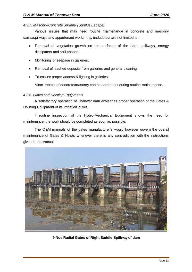
4.3.7. Masonry/Concrete Spillway (Surplus Escape)
Various issues that may need routine maintenance in concrete and masonry
dams/spillways and appurtenant works may include but are not limited to:
Removal of vegetation growth on the surfaces of the dam, spillways, energy
dissipaters and spill channel.
Monitoring of seepage in galleries.
Removal of leached deposits from galleries and general cleaning.
To ensure proper access & lighting in galleries.
Minor repairs of concrete/masonry can be carried out during routine maintenance.
4.3.8. Gates and Hoisting Equipments
A satisfactory operation of Thanwar dam envisages proper operation of the Gates &
Hoisting Equipment of its Irrigation outlet.
If routine inspection of the Hydro-Mechanical Equipment shows the need for
maintenance, the work should be completed as soon as possible.
The O&M manuals of the gates manufacturer’s would however govern the overall
maintenance of Gates & Hoists whenever there is any contradiction with the instructions
given in the Manual.
9 Nos Radial Gates of Right Saddle Spillway of dam

O & M Manual of Thanwar Dam June 2020
Page 34
Spillway Trunnion Bridge
O & M Manual of Thanwar Dam June 2020
Page 35
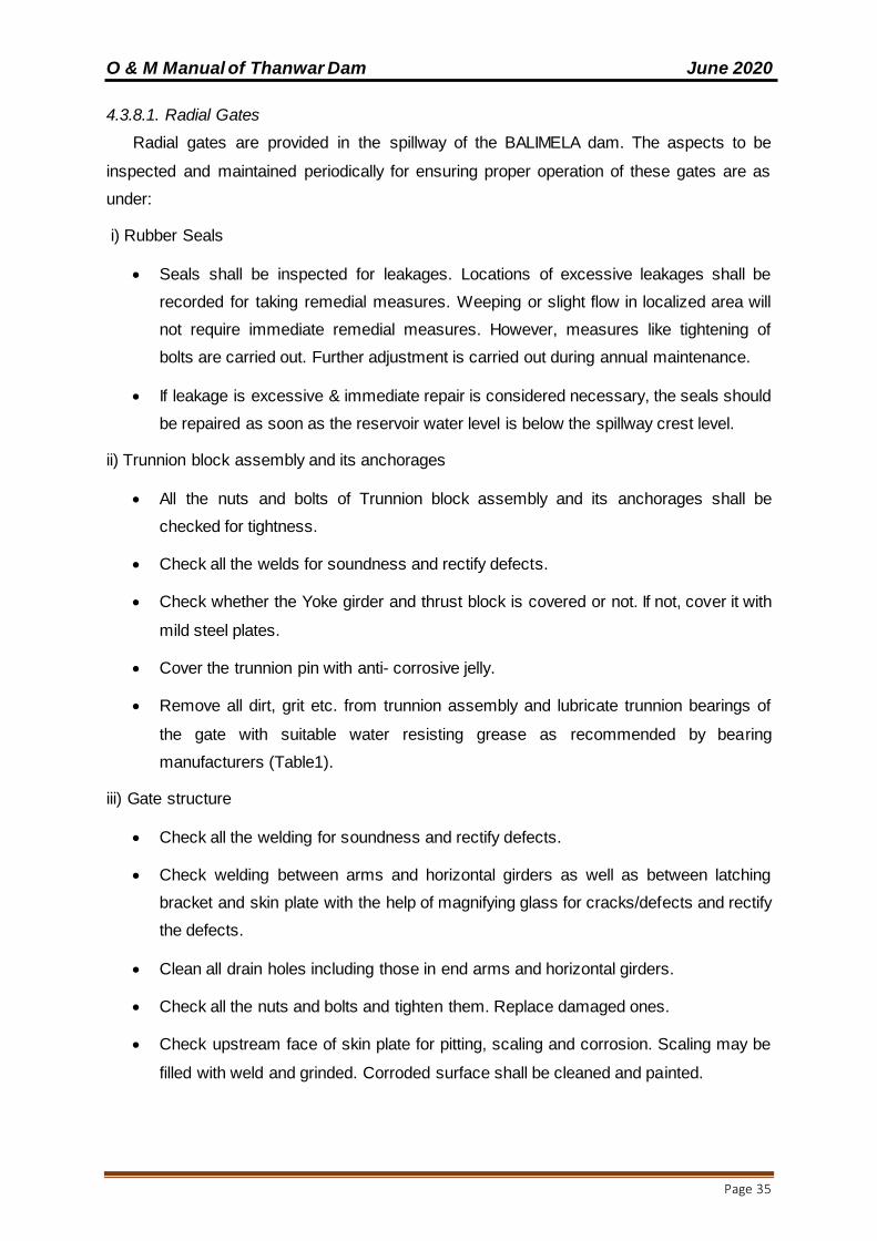
4.3.8.1. Radial Gates
Radial gates are provided in the spillway of the BALIMELA dam. The aspects to be
inspected and maintained periodically for ensuring proper operation of these gates are as
under:
i) Rubber Seals
Seals shall be inspected for leakages. Locations of excessive leakages shall be
recorded for taking remedial measures. Weeping or slight flow in localized area will
not require immediate remedial measures. However, measures like tightening of
bolts are carried out. Further adjustment is carried out during annual maintenance.
If leakage is excessive & immediate repair is considered necessary, the seals should
be repaired as soon as the reservoir water level is below the spillway crest level.
ii) Trunnion block assembly and its anchorages
All the nuts and bolts of Trunnion block assembly and its anchorages shall be
checked for tightness.
Check all the welds for soundness and rectify defects.
Check whether the Yoke girder and thrust block is covered or not. If not, cover it with
mild steel plates.
Cover the trunnion pin with anti- corrosive jelly.
Remove all dirt, grit etc. from trunnion assembly and lubricate trunnion bearings of
the gate with suitable water resisting grease as recommended by bearing
manufacturers (Table1).
iii) Gate structure
Check all the welding for soundness and rectify defects.
Check welding between arms and horizontal girders as well as between latching
bracket and skin plate with the help of magnifying glass for cracks/defects and rectify
the defects.
Clean all drain holes including those in end arms and horizontal girders.
Check all the nuts and bolts and tighten them. Replace damaged ones.
Check upstream face of skin plate for pitting, scaling and corrosion. Scaling may be
filled with weld and grinded. Corroded surface shall be cleaned and painted.
O & M Manual of Thanwar Dam June 2020
Page 36
iv) Embedded Parts
All the sill beams and wall plates shall be inspected for crack, pitting etc. and defects
shall be rectified.
The guide roller pins shall be lubricated (Table-1).
v) General Maintenance
Defective welding should be chipped out and it should be re-welded duly following
the relevant Codal provision (IS: 10096, Part-3).
Damaged nuts, bolts, rivets, screws etc. should be replaced.
Any pitting should be filled up by welding and finished by grinding if necessary.
The gate leaf, exposed embedded metal parts, hoists and hoist supporting structure
etc., should be thoroughly cleaned and repainted when required keeping in view the
original painting system adopted and as per the guidelines contained in IS: 14177.
Trunnion bearing should be greased as and when required (Table-1). Keeping
trunnion bearings in perfect working condition is very important. All other bolted
connections should also be checked up for proper tightness.
Bolts and Trunnion bearing housing should be tightened wherever required.
The seals of the gate should be checked for wear and tear and deterioration. These
should be adjusted/replaced as and when necessary.
The wall plates, sill beams shall be checked and repaired if necessary.
Wire ropes should be properly lubricated (Table-1).
Oil level in the worm reduction unit should be maintained by suitable replenishment.
Oil seals should also be replaced if required. Lubrication of other parts of hoists such
as chains, position indicators and limit switches should also be done (Table-1).
The stroke of the brake should be reset to compensate for lining wear. Worn out
brake linings should be replaced in time.
Flexible couplings should be adjusted if required. • Repairs and replacements of all
electrical relays and controls should be attended to.
Maintenance of alternative sources of Power such as Diesel Generating sets and
alternative drives wherever provided should be carried out.
O & M Manual of Thanwar Dam June 2020
Page 37
The list of essential spare parts to be kept available should be reviewed and updated
periodically. The condition of spares should be checked periodically and protective
coating given for use.
4.3.8.2 Electrically operated fixed hoists
i) General Instructions
Operation of fixed hoist without lifting the gate is not possible and need not therefore
be attempted. It will be possible to operate the unit and observe operation of load
carrying hoist component when gate is being lifted or lowered.
Never open any bolt or nut on motor, gear boxes, rope drums and other load carrying
hoist components when the gate is in raised position. The gate should be fully closed
or rested on the gate latches before carrying out any work on hoist components
including motor brake and other electrical equipment.
b) Inspection and Maintenance
The aspects to be inspected and maintained periodically for ensuring proper
operation of Rope drum hoists are as under;
Entrance to all hoist platforms shall be kept locked. All keys shall remain with the
shift supervisor.
A cursory daily inspection shall be made of hoist and gate to ensure that there is no
unusual happening.
Clean all hoisting equipment and hoist platform.
Check oil level in gearboxes and replenish as and when required with oil of proper
grade.
Apply grease of suitable grade by grease gun (Table-1).
Lubricate all bearings, bushings, pins, linkages etc. (Table-1).
Check all the fuses on the power lines.
All bolts and nuts on gear boxes, hoist drum and shaft couplings should be checked
for tightness.
Check the supply voltage.
Drain sample gear oil from each of the gear boxes. If excessive foreign particles or
sludge is found, the gear box shall be drained, flushed and filled with new oil.
All the geared couplings shall be greased (Table-1).

O & M Manual of Thanwar Dam June 2020
Page 38
Raise and lower the gate by hoist motor and check for smooth, and trouble free
operation of gate without excessive vibration.
Observe current drawn by motor at the time of lifting and check if it is more than
normal. If so, stop the hoist and investigate the cause and rectify.
Check the condition of painting of various components and remove rust wherever
noticed and repaint the portion after proper cleaning as per painting schedule.
All trash, sediments and any other foreign material shall be cleared off the lifting rope
and lifting attachment.
All ropes shall be checked for wear and tear and if broken wires are noticed, the rope
shall be replaced.
All the wire ropes shall be checked and all visible oxidation shall be removed.
All wire ropes shall be greased with cadmium compound (Table-1).
Check the overload relays for proper functioning.
Check all the nuts, bolts, rivets, welds and structural components for hoisting
platform and its supporting structure for wear, tear and damage. All damages shall
be rectified. All bolts shall be tightened. The portion with damaged painting shall be
touched up.
Check the pulleys, sheaves and turn-buckles.
Raise and lower the gate for its full lift several times (at least three to four) and
observe the following: -
- Check the limit switches and adjust for design limits
- The effectiveness and slip of the breaks shall be checked by stopping the gate in
raising and lowering operations. The brakes shall be adjusted if needed.
- When the gate is operated, there should not be any noise or chatter in the gears.
Adjust the rope tension of wires if unequal.
Check for all gears and pinions for uneven wear and adjust for proper contact.
Grease the gears (Table-1).
Repaint the hoist components, hoisting platform and its supporting structures as per
requirement.
The periodic maintenance of commercial equipment like motors, brakes, thrusts etc.
shall be carried out as per manufacturers operation and maintenance manual.

O & M Manual of Thanwar Dam June 2020
Page 39
4.3.8.3 Maintenance of Electrical components of Fixed Rope Drum Hoists
The Electrical components to be inspected and maintained periodically are as under;
Starters should be cleaned free of moisture and dust.
Each individual contactor should be tried by hand to make sure that it operates
freely.
All wearing parts should be examined in order to take note of any wear which may
have occurred during operation.
If the contactor hums, the contact faces should be cleaned.
Examine all connections to see that no wires are broken and no connections are
loose.
Clean the surface of the moving armature and magnet core which comes together
when the contactor closes, free of dust or grease of any kind.
Examine the mechanical interlocks between the reversing contactor and see when
the contact tips of one of the contactor units are touching, it is impossible to get the
contact tips of the other unit to touch.
The contact tips should be kept free from burns or pits by smoothening with fine sand
paper or emery paper.
Replace the contact tips which have worn away half-way.
Do not lubricate the contacts.
Blow out windings thoroughly by clean and dry air to clear air passage in the stator
and the rotor of any accumulated dirt. The air pressure shall not be too high to
damage the insulation.
Examine earth connections and motor leads.
Examine motor windings for overheating
Examine control equipment’s
Examine starting equipment for burnt contacts
Check and tighten all nuts and bolts
Clean and tighten all terminals and screw connections all contact surfaces shall be
made clean and smooth.
Lubricate the bearings

O & M Manual of Thanwar Dam June 2020
Page 40
Overhaul the controllers
Inspect and clean circuit breakers.
Wipe brush holders and check bedding of brushes.
Blow out windings thoroughly by clean and dry air. The pressure shall not be so high
that insulation may get damaged.
Check the insulation resistance of the motor between any terminal and the frame. If
the measured resistance is less than the prescribed value, then steps shall be taken
to dry- out the motors either by passing a low voltage current through the windings or
by placing the stator and rotor only in a warm dry place for a day or so.
Important: The complete motor shall never be put in an oven for drying as that may melt the
grease out of bearings.
Coat the windings with an approved high temperature resisting insulation enamel or
varnish.
Over haul the motor, if required.
Check the switch fuse units and renew, if required.
Check resistance or earth connections.
Check air gap.
Solenoids Operated Brakes
All fixing bolts shall be checked and tightened at least once in three months.
The magnet stroke should be reset to compensate for wear.
Re-adjust the brake when the magnet stroke reaches the value given on the
instruction plate.
Brake lining should be checked and replaced when required.
Examine all electrical leads and connections.
Rubber bushes or couplings should be checked and replaced if defective.
The pins should be tightened.
Brake drum shall be cleaned to remove any dust or grease.
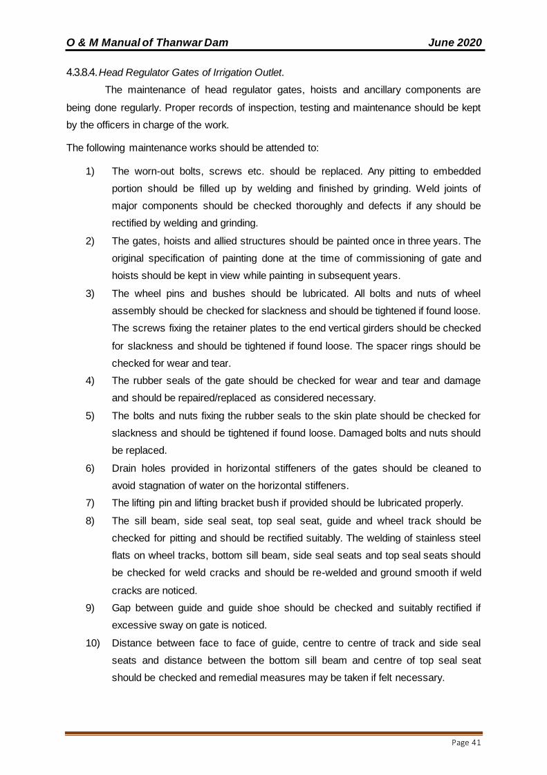
O & M Manual of Thanwar Dam June 2020
Page 41
4.3.8.4. Head Regulator Gates of Irrigation Outlet.
The maintenance of head regulator gates, hoists and ancillary components are
being done regularly. Proper records of inspection, testing and maintenance should be kept
by the officers in charge of the work.
The following maintenance works should be attended to:
1) The worn-out bolts, screws etc. should be replaced. Any pitting to embedded
portion should be filled up by welding and finished by grinding. Weld joints of
major components should be checked thoroughly and defects if any should be
rectified by welding and grinding.
2) The gates, hoists and allied structures should be painted once in three years. The
original specification of painting done at the time of commissioning of gate and
hoists should be kept in view while painting in subsequent years.
3) The wheel pins and bushes should be lubricated. All bolts and nuts of wheel
assembly should be checked for slackness and should be tightened if found loose.
The screws fixing the retainer plates to the end vertical girders should be checked
for slackness and should be tightened if found loose. The spacer rings should be
checked for wear and tear.
4) The rubber seals of the gate should be checked for wear and tear and damage
and should be repaired/replaced as considered necessary.
5) The bolts and nuts fixing the rubber seals to the skin plate should be checked for
slackness and should be tightened if found loose. Damaged bolts and nuts should
be replaced.
6) Drain holes provided in horizontal stiffeners of the gates should be cleaned to
avoid stagnation of water on the horizontal stiffeners.
7) The lifting pin and lifting bracket bush if provided should be lubricated properly.
8) The sill beam, side seal seat, top seal seat, guide and wheel track should be
checked for pitting and should be rectified suitably. The welding of stainless steel
flats on wheel tracks, bottom sill beam, side seal seats and top seal seats should
be checked for weld cracks and should be re-welded and ground smooth if weld
cracks are noticed.
9) Gap between guide and guide shoe should be checked and suitably rectified if
excessive sway on gate is noticed.
10) Distance between face to face of guide, centre to centre of track and side seal
seats and distance between the bottom sill beam and centre of top seal seat
should be checked and remedial measures may be taken if felt necessary.
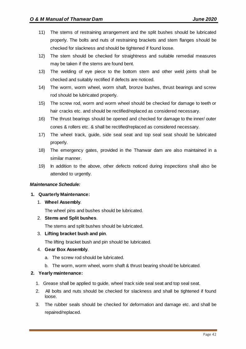
O & M Manual of Thanwar Dam June 2020
Page 42
11) The stems of restraining arrangement and the split bushes should be lubricated
properly. The bolts and nuts of restraining brackets and stem flanges should be
checked for slackness and should be tightened if found loose.
12) The stem should be checked for straightness and suitable remedial measures
may be taken if the stems are found bent.
13) The welding of eye piece to the bottom stem and other weld joints shall be
checked and suitably rectified if defects are noticed.
14) The worm, worm wheel, worm shaft, bronze bushes, thrust bearings and screw
rod should be lubricated properly.
15) The screw rod, worm and worm wheel should be checked for damage to teeth or
hair cracks etc. and should be rectified/replaced as considered necessary.
16) The thrust bearings should be opened and checked for damage to the inner/ outer
cones & rollers etc. & shall be rectified/replaced as considered necessary.
17) The wheel track, guide, side seal seat and top seal seat should be lubricated
properly.
18) The emergency gates, provided in the Thanwar dam are also maintained in a
similar manner.
19) In addition to the above, other defects noticed during inspections shall also be
attended to urgently.
Maintenance Schedule:
1. Quarterly Maintenance:
1. Wheel Assembly.
The wheel pins and bushes should be lubricated.
2. Stems and Split bushes.
The stems and split bushes should be lubricated.
3. Lifting bracket bush and pin.
The lifting bracket bush and pin should be lubricated.
4. Gear Box Assembly.
a. The screw rod should be lubricated.
b. The worm, worm wheel, worm shaft & thrust bearing should be lubricated.
2. Yearly maintenance:
1. Grease shall be applied to guide, wheel track side seal seat and top seal seat.
2. All bolts and nuts should be checked for slackness and shall be tightened if found loose.
3. The rubber seals should be checked for deformation and damage etc. and shall be
repaired/replaced.
O & M Manual of Thanwar Dam June 2020
Page 43
4.3.8.5. Painting of Spillway & Head Regulator Gates and Hoists.
i) Protection of painted surfaces is considered essential for protection & enhancement of
service life.
Gates, its embedded parts, gate leaf, hoists and its supporting structures need to be
protected against corrosion due to climatic condition, weathering, biochemical reaction
and abrasion etc. These equipments are likely to deteriorate/ damage to the extent that
replacement of parts may become necessary and such replacement may become
difficult and costly.
ii) Surface preparation & Painting requirements.
Painting for hydro-mechanical works is to be carried out as prescribed in IS 14177 for
both newly manufactured as well as old & used gates, hoists and associated works after
proper surface preparation. The preparation includes thorough cleaning, smoothing
irregular surfaces, rusted surfaces, weld spatters, oil, grease, dirt, earlier applied
damaged layers of primers/paint by use of mechanical tools, by use of solvents, wire
brush etc. The sand/grit blasting process is used for surface preparation to a level of Sa
2½ of the Swedish standard.
iii) Surfaces not requiring painting & their protection during surface preparation, painting &
transportation process.
a) The following surfaces are not to be painted unless or otherwise specified:
• Machine finished or similar surface
• Surfaces which will be in contact with concrete
• Stainless steel overlay surfaces.
• Surfaces in sliding or rolling contact
• Galvanized surfaces, brass and bronze surfaces.
• Aluminum alloy surfaces
b) The Surfaces of stainless steel, nickel, bronze and machined surface adjacent to
metal work being cleaned or painted shall be protected by using sticky protective
tape or by other suitable means over the surfaces not to be painted.
c) All embedded parts which come in contact with concrete shall be cleaned as
detailed above and given two coats of cement latex to prevent rusting during the
shipment while awaiting installation.
iv) Application of primer & finish coats on embedded parts and gates
a) Embedded parts

O & M Manual of Thanwar Dam June 2020
Page 44
• The prescribed primer shall be applied as soon as the surface preparation is
complete and prior to the development of surface rusting and within the specified
time prescribed by Indian Standards or the Paint Manufacturer. In case there is
lapse of considerable time beyond the prescribed time limit, the surfaces shall be
again cleaned prior to priming.
• Two coats of zinc rich primer with epoxy resin shall be applied to all embedded
parts surfaces which are not in contact with concrete and shall remain exposed to
atmosphere or submerged in water to obtain a dry film thickness of 75 microns.
• This shall be followed by three coats at an interval of 24 hours of coal-tar blend
epoxy resin so as to get a dry film thickness of 80 microns in each coat. Total dry
film thickness of paint shall not be less than 300 microns.
b) Gates
Primer Coat
Over the prepared surface one coat of inorganic zinc silicate primer giving a dry film
thickness of 70 ± 5 microns should be applied. Alternatively two coats of zinc rich
primer, which should contain not less than 85% zinc on dry film should be applied to
give a total dry film thickness of 75 ± 5 microns.
Finished paint
Two coats of solvent less coal tar epoxy paints. These shall be applied at an interval
of about 24 hours. Each coat shall give a dry film thickness of 150±5 microns. The
total dry film thickness of all the coats including primer coating shall not be less than
350 microns.
Table – 7 a (Radial Gates and Hoists)
Sl. No.
Parts to be Lubricated
Method of Lubrication
When to Lubricate Lubricants
Recommended
1 Trunnion Assembly (Brushes and Pins)
Volume grease gun
Quarterly Mobil Grease
No. 2
2 Guide roller
Assembly (bushes and pins)
Hand grease gun Quarterly Mobil Grease
No. 2
3 Gerars and Pinions
of end reduction gear boxes
By brush/hand Quarterly Dorcia 150
4
Hinges, pins and spring of
Electromagnetic brake
Hand grease gun Quarterly Mobil Grease
No. 2
5 Gears and pinions
of position Indicators
By brush/hand Quarterly Dorcia 150

O & M Manual of Thanwar Dam June 2020
Page 45
6 Bushes of position
Indicators By oil can Quarterly DTE oil Medium
7 Electric Motor
Bearings Hand grease gun Yearly
Mobil Grease No. 2
8 Wire ropes By brush/Hand Half Yearly Cadmium compound
9 Worm gear reducer Fill upto mark on
dip stick Change oil in alternate year
Servo C-60 or Servo Mark 59
SAE-140
10 Anti-friction bearings
Hand grease gun Yearly Mobil Grease No. 2
11
Pins of Wire rope attachment turn
buckles and equaliser plate turn-
buckle thread
By grease gun Yearly Mobil Grease
No. 2
12 Drum shaft bushing Volume grease
gun Yearly
Mobil Grease
No. 2
13 Limit Switches By oil can Yearly Mobil Oil
Table – 7 b (Head Regulator Gates and Screw Hoists)
Sl. No.
Parts to be Lubricated
Method of Lubrication
When to Lubricate Lubricants
Recommended
1. Wheel Assembly (Pin & Bushes)
Volume Grease Gun
Quarterly Mobil Grease
No. 2
2. Worm Wheel,
Worm, Worm shaft and screw rod
Smear Quarterly Mobil Grease
3. Bushes of Gear Box By Oilcan Quarterly DTE Oil
4. Restraining stems &
split bushes Smear Quarterly Mobil Grease
5. Lifting Bracket Bush
and Pin Smear Quarterly Mobil Grease
6. Thrust Bearing Smear Quarterly Mobil Grease
No. 2
7. Guide, Wheel Track
side Seal Seat & Top Seal Seat
Smear Yearly Dorcia 150
Note: Lubricants of other make equivalent to the lubricants specified above can also be
used.
(1) Keep a list of spare parts.
(2) Detail of DG set (Capacity, Capability to operate the nos. of gates and facilities, its
operation and maintenance) in event of emergency / power failure should be readily
available at site.
(3) Details of control panels used for operation of gates should be readily available at
site.
O & M Manual of Thanwar Dam June 2020
Page 46
4.3.9. Electrical System:
Head regulator shutters are operated manually and spillway is gated. There is supply of
electricity to the project site. Lighting arrangement has been made at site till date.
4.3.10. Metal Component maintenance:
Head regulator shutters of bare ferrous metal will tend to rust. To prevent corrosion,
shutters must be either appropriately painted (following the paint manufacturer’s directions)
or heavily greased in respect of moving parts & on surfaces like guide channels on which
there is movement of gates. When areas are repainted, it should be ensured that paint is not
applied to gate seats, wedges, or stems (where they pass through the stem guides), or on
other friction surfaces where paint could cause binding. Heavy grease should be applied on
friction surfaces to avoid binding. As rust is especially damaging to contact surfaces, existing
rust is to be removed before periodic application of grease.
4.3.11. Access Road:
For a dam to be operated and maintained there must be a safe means of access to it
at all times. Access road surfaces must be maintained to allow safe passage of automobiles
and any required equipment for servicing the dam in any weather conditions. Routine
observations of any cut and fill slopes along the sides of the road should be made. If
unstable conditions develop assistance of experienced Engineers/Expert Panels should be
obtained and remedial measures initiated.
Drains are required to be provided and maintained along roads to remove surface
and subsurface drainage. This will prolong the life of the road and help reduce deterioration
from rutting. Road surfacing should be repaired or replaced as necessary to maintain the
required traffic loadings. In most cases, specialized contractors will be required to perform
this maintenance.
An all-weather black topped approach road with carriage way width of 3.5 m to the
dam has been constructed for movement of machines and dam authorities throughout the
year.
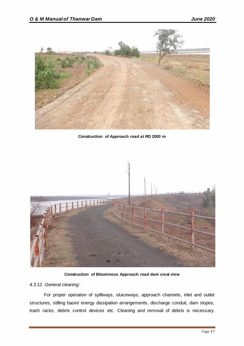
O & M Manual of Thanwar Dam June 2020
Page 47
Construction of Approach road at RD 2000 m
Construction of Bituminous Approach road dam crest view
4.3.12. General cleaning:
For proper operation of spillways, sluiceways, approach channels, inlet and outlet
structures, stilling basin/ energy dissipation arrangements, discharge conduit, dam slopes,
trash racks, debris control devices etc. Cleaning and removal of debris is necessary.
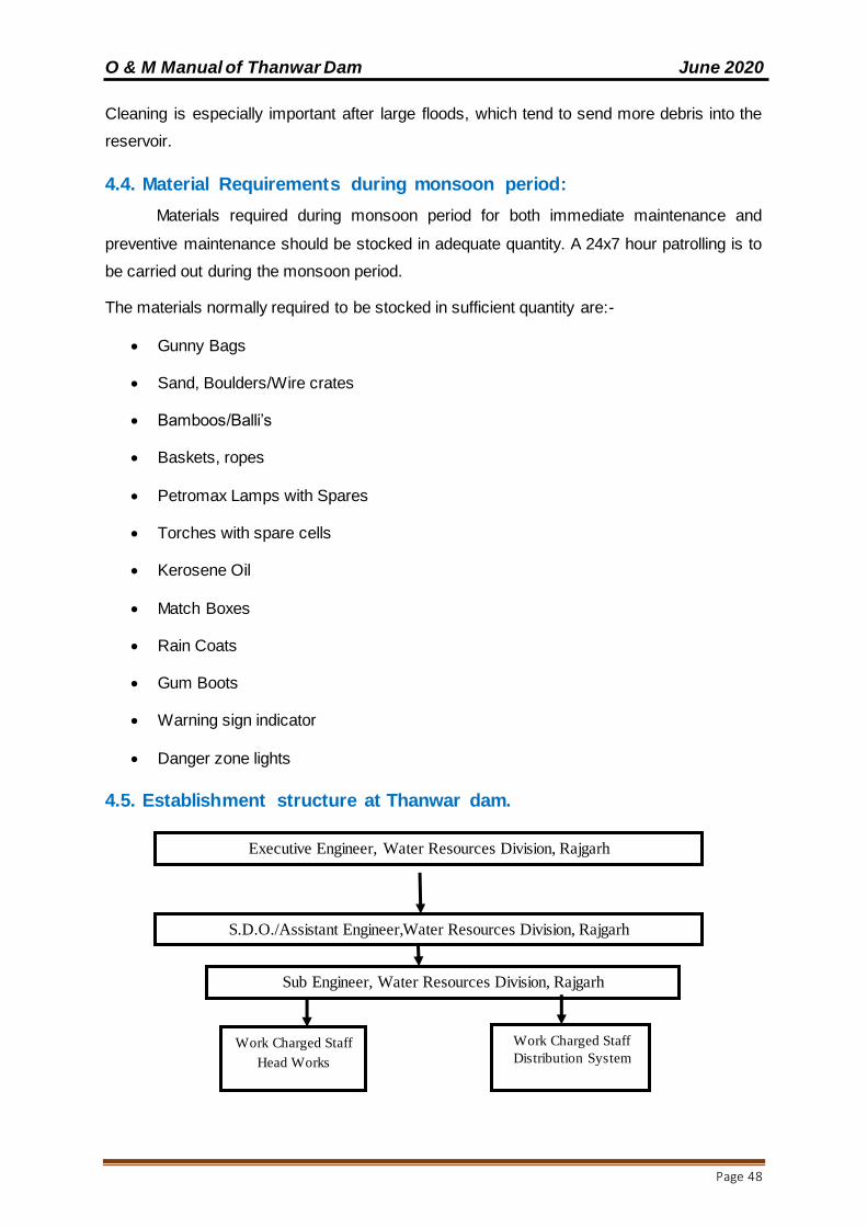
O & M Manual of Thanwar Dam June 2020
Page 48
Cleaning is especially important after large floods, which tend to send more debris into the
reservoir.
4.4. Material Requirements during monsoon period:
Materials required during monsoon period for both immediate maintenance and
preventive maintenance should be stocked in adequate quantity. A 24x7 hour patrolling is to
be carried out during the monsoon period.
The materials normally required to be stocked in sufficient quantity are:-
Gunny Bags
Sand, Boulders/Wire crates
Bamboos/Balli’s
Baskets, ropes
Petromax Lamps with Spares
Torches with spare cells
Kerosene Oil
Match Boxes
Rain Coats
Gum Boots
Warning sign indicator
Danger zone lights
4.5. Establishment structure at Thanwar dam.
Executive Engineer, Water Resources Division, Rajgarh
S.D.O./Assistant Engineer,Water Resources Division, Rajgarh
Sub Engineer, Water Resources Division, Rajgarh
Work Charged Staff
Head Works
Work Charged Staff
Distribution System
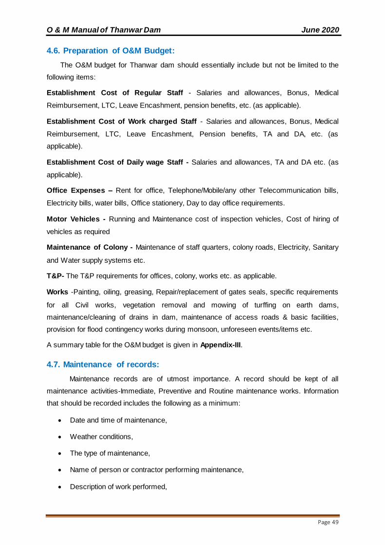
O & M Manual of Thanwar Dam June 2020
Page 49
4.6. Preparation of O&M Budget:
The O&M budget for Thanwar dam should essentially include but not be limited to the
following items:
Establishment Cost of Regular Staff - Salaries and allowances, Bonus, Medical
Reimbursement, LTC, Leave Encashment, pension benefits, etc. (as applicable).
Establishment Cost of Work charged Staff - Salaries and allowances, Bonus, Medical
Reimbursement, LTC, Leave Encashment, Pension benefits, TA and DA, etc. (as
applicable).
Establishment Cost of Daily wage Staff - Salaries and allowances, TA and DA etc. (as
applicable).
Office Expenses – Rent for office, Telephone/Mobile/any other Telecommunication bills,
Electricity bills, water bills, Office stationery, Day to day office requirements.
Motor Vehicles - Running and Maintenance cost of inspection vehicles, Cost of hiring of
vehicles as required
Maintenance of Colony - Maintenance of staff quarters, colony roads, Electricity, Sanitary
and Water supply systems etc.
T&P- The T&P requirements for offices, colony, works etc. as applicable.
Works -Painting, oiling, greasing, Repair/replacement of gates seals, specific requirements
for all Civil works, vegetation removal and mowing of turffing on earth dams,
maintenance/cleaning of drains in dam, maintenance of access roads & basic facilities,
provision for flood contingency works during monsoon, unforeseen events/items etc.
A summary table for the O&M budget is given in Appendix-III.
4.7. Maintenance of records:
Maintenance records are of utmost importance. A record should be kept of all
maintenance activities-Immediate, Preventive and Routine maintenance works. Information
that should be recorded includes the following as a minimum:
Date and time of maintenance,
Weather conditions,
The type of maintenance,
Name of person or contractor performing maintenance,
Description of work performed,
O & M Manual of Thanwar Dam June 2020
Page 50
The length of time it took to complete the work with dates,
Equipment and materials used, and
Before and after photographs.
The data should be recorded by the person responsible for maintenance.

O & M Manual of Thanwar Dam June 2020
Page 51
CHAPTER 5 INSTRUMENTATION AND MONITORING
At present there are two Rain Gauge stations (old equipment/ manual process)
installed at Beejegaon and Dithiri and two nos of V-notches are installed at Thanwar River
and Dattla Nalla. However gauge at discharge site is proposed to be install under Drip
project. The details of the instruments installed and frequency of measurements is given
below:
The details of the instruments proposed to be installed and frequency of measurements
is given below:
Table – 8
Note:-
Monsoon – 15Th June to 15th October
Non- Monsoon – 15th Nov. to 14th June of the water year
Sl. No.
Instrument Frequency Personnel
1 V-Notch Daily during monsoon and weekly during non-monsoon
Junior Engineer
2 Total Weather station Daily Junior Engineer
3 Automatic Reservoir level Recorder
Daily during non-monsoon and hourly during monsoon
Junior Engineer
4 Water level gauge at dam for manual observation of reservoir level
Daily during non-monsoon and hourly during monsoon
Junior Engineer

O & M Manual of Thanwar Dam June 2020
Page 52
This page is left blank intentionally

O & M Manual of Thanwar Dam June 2020
Page 53
CHAPTER 6: PREVIOUS REHABILITATION EFFORTS.
Before DRIP, maintenance activities were limited to routine greasing, oiling, and
patch painting of shutter gates, routine mowing, vegetation removal, repair of eroded
section, etc. Apart from these routine maintenance activities, Remedial measure works has
been done, which is enlisted below.
Under DRIP, major Rehabilitation Works have been carried out for Thanwar dam at a
total cost of about INR 493 Lakhs. The rehabilitation works carried out under DRIP include:
1. Civil work
Restoration of D/S of bund by earth work,
Restoration of parapet wall on main dam
Concrete work in front of exist of head sluice,
Concrete work in cavities of spill channel,
Concrete work in bed of approach channel of head sluice
Pitching in side slope and construction of check boulder bund
Repairing of U/S boulder toe of bund
Construction of control room over pier no 1,
Construction of staff quarter at gated spillway site for gate operating staff.
2. Electrical and mechanical works
Painting the hydro mechanical structures of spill way such as redial gates
stop log gets etc.,
Changing the rubber seal of redial gates and stop log gates,
Providing and fixing solar light system in the Thanwar dam
3. Drilling and Grouting works
Repair of leakage through construction joint of spillway block No. 1 by cement
grouting work.
4. Construction of bituminous road works

O & M Manual of Thanwar Dam June 2020
Page 54
O & M Manual of Thanwar Dam June 2020
Page 55
Other non-structural measures carried out under DRIP include preparation of
Inundation maps and Emergency Action Plan (EAP); Review of design flood; Preparation of
O & M Manual; Data entry to DHARMA; etc.

O & M Manual of Thanwar Dam June 2020
Page 56
This page is left blank intentionally

O & M Manual of Thanwar Dam June 2020
Page 57
CHAPTER 7: UPDATING THE MANUAL.
The O & M Manual is to be reviewed and updated periodically. Updating of O&M
Manual should be done whenever any major changes occur like revision of design flood,
construction of additional Surplus Escape (Spillway), construction of dam on the upstream
etc.
Aspects to be considered when updating include:
Increase/decrease in the frequency of inspection or routine maintenance based on
additional data/ experience acquired.
Changes in the operation and/or maintenance procedures based on additional
data/experience acquired.
Alterations to the project data because of changes/modifications in the dam by way
of construction of any additional surplus escape (Spillway), u/s and d/s developments
etc.
All up-dates/revisions of the O&M Manual need to be sent to all the
locations/addresses to which the copies of the original O&M Manual had been sent earlier.
The O&M Manual is to be normally reviewed/ updated after every 10 years or earlier by the
Executive Engineer, Water Resources Division, Mandla.
Updates in the O & M Manual will be approved by the Chief Engineer of the project
after getting the needful checking done through the DSO of MPWRD.
7.1 Training and Exercises:
Training: The training of the personnel, involved in implementation of the O & M Manual will
be conducted by the SE once in a year so as to make the implementing staff familiar with
the elements of the O&M plan, their responsibilities and duties, the available equipment,
detection of problems and remedial measures.
A sufficient number of people will be trained to ensure adequate expertise at all times.
Exercises (Testing): The SE shall carry out orientation meetings with personnel involved in
implementation of the O&M Manual and organize mock drills for head regulator gates before
every crop season.

O & M Manual of Thanwar Dam June 2020
Page 58
This page is left blank intentionally
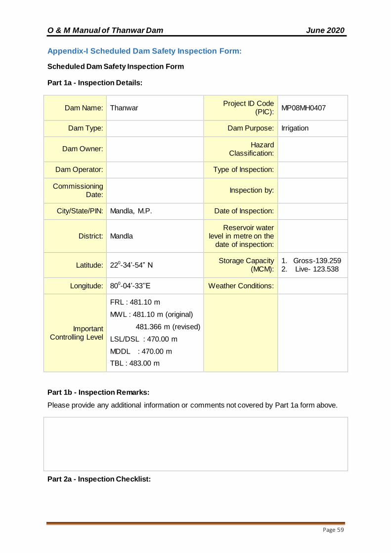
O & M Manual of Thanwar Dam June 2020
Page 59
Appendix-I Scheduled Dam Safety Inspection Form:
Scheduled Dam Safety Inspection Form
Part 1a - Inspection Details:
Dam Name: Thanwar Project ID Code
(PIC): MP08MH0407
Dam Type: Dam Purpose: Irrigation
Dam Owner: Hazard
Classification:
Dam Operator: Type of Inspection:
Commissioning Date:
Inspection by:
City/State/PIN: Mandla, M.P. Date of Inspection:
District: Mandla Reservoir water
level in metre on the date of inspection:
Latitude: 220-34’-54” N Storage Capacity
(MCM): 1. Gross-139.259 2. Live- 123.538
Longitude: 800-04’-33’’E Weather Conditions:
Important Controlling Level
FRL : 481.10 m
MWL : 481.10 m (original)
481.366 m (revised)
LSL/DSL : 470.00 m
MDDL : 470.00 m
TBL : 483.00 m
Part 1b - Inspection Remarks:
Please provide any additional information or comments not covered by Part 1a form above.
Part 2a - Inspection Checklist:

O & M Manual of Thanwar Dam June 2020
Page 60
S. No. Inspection Item Responsea
Observations and recommendations, if
any, of the authorized
inspecting officer
Conditionb
(Unsatisfactory/Poor/Fair/
Satisfactory)
Y N NA
A-Reservoir
A-1.1 General Condition
1.1.1 Is the reservoir water level unusually high or low?
1.1.2 Are there signs of decline in water quality?
1.1.3 Are there signs of recent sediment deposition?
1.1.4 Is floating debris present?
1.1.5 Any indications of major active or inactive landslide area in the reservoir rim
If so, indicate their locations and extent.
1.1.6 Are there people or livestock in and around reservoir?
1.1.7 Any other issues?
B-Dam and Dam Reach (Embankment)
B-1.1 General Condition
1.1.1 Any major alterations or changes to the dam
since the last inspection?
1.1.2 Is there any new nearby development in the downstream floodplain?
1.1.3 Any misalignment of poles, fencing or walls due to dam movement?
B-1.2 Upstream Slope
1.2.1 Any signs of bulging or concavity (depressions)?
If so, indicate their locations and extent.
(Check up the cross-sections with tape and level at random locations, at least two)
1.2.2 Does the section of the dam and upstream slope appear structurally sound and stable?
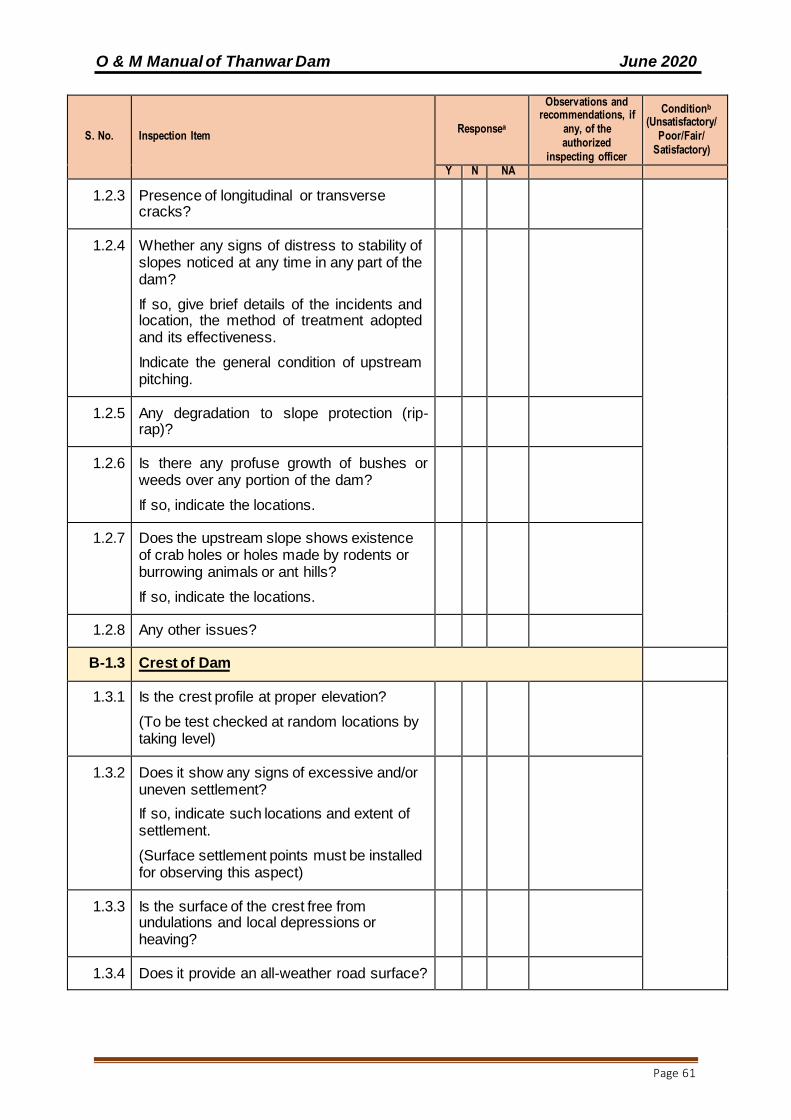
O & M Manual of Thanwar Dam June 2020
Page 61
S. No. Inspection Item Responsea
Observations and recommendations, if
any, of the authorized
inspecting officer
Conditionb
(Unsatisfactory/Poor/Fair/
Satisfactory)
Y N NA
1.2.3 Presence of longitudinal or transverse cracks?
1.2.4 Whether any signs of distress to stability of slopes noticed at any time in any part of the dam?
If so, give brief details of the incidents and location, the method of treatment adopted and its effectiveness.
Indicate the general condition of upstream pitching.
1.2.5 Any degradation to slope protection (rip-rap)?
1.2.6 Is there any profuse growth of bushes or weeds over any portion of the dam?
If so, indicate the locations.
1.2.7 Does the upstream slope shows existence of crab holes or holes made by rodents or burrowing animals or ant hills?
If so, indicate the locations.
1.2.8 Any other issues?
B-1.3 Crest of Dam
1.3.1 Is the crest profile at proper elevation?
(To be test checked at random locations by taking level)
1.3.2 Does it show any signs of excessive and/or uneven settlement?
If so, indicate such locations and extent of settlement.
(Surface settlement points must be installed for observing this aspect)
1.3.3 Is the surface of the crest free from undulations and local depressions or heaving?
1.3.4 Does it provide an all-weather road surface?
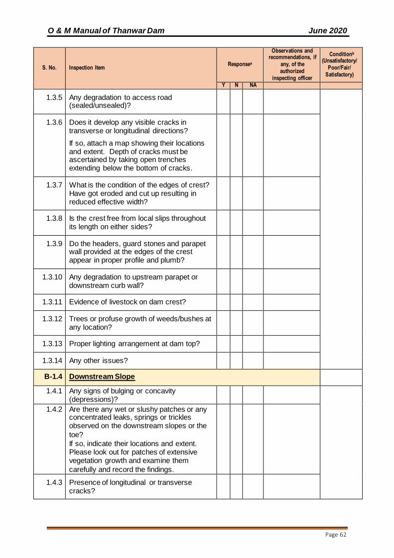
O & M Manual of Thanwar Dam June 2020
Page 62
S. No. Inspection Item Responsea
Observations and recommendations, if
any, of the authorized
inspecting officer
Conditionb
(Unsatisfactory/Poor/Fair/
Satisfactory)
Y N NA
1.3.5 Any degradation to access road (sealed/unsealed)?
1.3.6 Does it develop any visible cracks in transverse or longitudinal directions?
If so, attach a map showing their locations and extent. Depth of cracks must be ascertained by taking open trenches extending below the bottom of cracks.
1.3.7 What is the condition of the edges of crest? Have got eroded and cut up resulting in reduced effective width?
1.3.8 Is the crest free from local slips throughout its length on either sides?
1.3.9 Do the headers, guard stones and parapet wall provided at the edges of the crest appear in proper profile and plumb?
1.3.10 Any degradation to upstream parapet or downstream curb wall?
1.3.11 Evidence of livestock on dam crest?
1.3.12 Trees or profuse growth of weeds/bushes at any location?
1.3.13 Proper lighting arrangement at dam top?
1.3.14 Any other issues?
B-1.4 Downstream Slope
1.4.1 Any signs of bulging or concavity (depressions)?
1.4.2 Are there any wet or slushy patches or any concentrated leaks, springs or trickles observed on the downstream slopes or the
toe?
If so, indicate their locations and extent. Please look out for patches of extensive vegetation growth and examine them
carefully and record the findings.
1.4.3 Presence of longitudinal or transverse cracks?

O & M Manual of Thanwar Dam June 2020
Page 63
S. No. Inspection Item Responsea
Observations and recommendations, if
any, of the authorized
inspecting officer
Conditionb
(Unsatisfactory/Poor/Fair/
Satisfactory)
Y N NA
1.4.4 Any signs of distress to the stability of slopes?
1.4.5 Are rain cuts/erosion channels present at any location?
1.4.6 Are all the rain cuts and erosion channels properly treated and made good? Please indicate location of recurring damages, if any.
1.4.7 Is there any profuse growth of bushes or weeds over any portion of the dam?
If so, indicate the locations.
1.4.8 Does the downstream slope shows existence of crab holes or holes made by rodents or burrowing animals or ant hills? If so, indicate the locations.
1.4.9 Any other degradation to slope protection (turffing)?
Indicate the general condition of downstream pitching/ turffing and rock toe.
1.4.10 Is the downstream area clear of debris and free draining?
1.4.11 Any other issues?
B-1.5 Downstream Drainage
1.5.1 Are there any signs of water logging, slushy conditions or growth of aquatic weeds on the downstream of the dam?
To be checked up to 300 m downstream of toe
1.5.2 Are there any standing pools of water in the downstream of dam? If so, give their locations and extent.
To be checked up to 300 m downstream of toe
1.5.3 Are there any boils observed in the vicinity of the downstream toe of the dam? If so, give locations.

O & M Manual of Thanwar Dam June 2020
Page 64
S. No. Inspection Item Responsea
Observations and recommendations, if
any, of the authorized
inspecting officer
Conditionb
(Unsatisfactory/Poor/Fair/
Satisfactory)
Y N NA
1.5.4 Is the downstream area sufficiently clear and free draining?
1.5.5 What is the depth of ground water table on the downstream as evident from the existing wells in the vicinity of the dam
To be checked up to 300 m downstream of toe. Does the water tableshow any marked variationinaccordancewiththe variations in reservoir water level?
a) Max. Ground water level………………
b) Location ……………
c) Date……………
d) Corresponding Reservoir level……
1.5.6 Are all the exposed drains working satisfactorily?
1.5.7 Toe drains and cross drains.
i. Are the portions of longitudinal toe drain and exposed cross drains beyond the downstream toe of the dam in regular section and freely draining?
ii. Is the pitching to these drains intact?
iii. Is there any weed growth in these drains?
iv. Indicate other defects noticed in the drains, if any.
1.5.8 Outfall Drain:
(a) Is the outfall drain in proper shape and grade and freely draining?
(b) Is the outfall drain properly cleaned and maintained?
Does the outfall drain show any stagnant pools of water or weed growth?
B-1.6 Surface Drainage of Downstream Slope
1.6.1 Is the condition of the downstream slope drainage arrangements, if provided, satisfactory?
1.6.2 Is the paving to these drains intact?
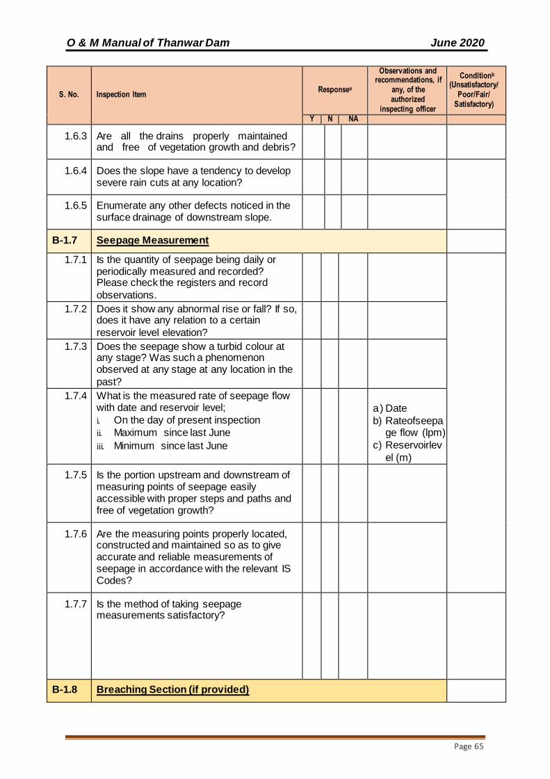
O & M Manual of Thanwar Dam June 2020
Page 65
S. No. Inspection Item Responsea
Observations and recommendations, if
any, of the authorized
inspecting officer
Conditionb
(Unsatisfactory/Poor/Fair/
Satisfactory)
Y N NA
1.6.3 Are all the drains properly maintained and free of vegetation growth and debris?
1.6.4 Does the slope have a tendency to develop severe rain cuts at any location?
1.6.5 Enumerate any other defects noticed in the surface drainage of downstream slope.
B-1.7 Seepage Measurement
1.7.1 Is the quantity of seepage being daily or periodically measured and recorded? Please check the registers and record
observations.
1.7.2 Does it show any abnormal rise or fall? If so, does it have any relation to a certain
reservoir level elevation?
1.7.3 Does the seepage show a turbid colour at any stage? Was such a phenomenon observed at any stage at any location in the
past?
1.7.4 What is the measured rate of seepage flow with date and reservoir level;
i. On the day of present inspection
ii. Maximum since last June
iii. Minimum since last June
a) Date
b) Rateofseepage flow (lpm)
c) Reservoirlev
el (m)
1.7.5 Is the portion upstream and downstream of measuring points of seepage easily accessible with proper steps and paths and free of vegetation growth?
1.7.6 Are the measuring points properly located, constructed and maintained so as to give accurate and reliable measurements of seepage in accordance with the relevant IS Codes?
1.7.7 Is the method of taking seepage measurements satisfactory?
B-1.8 Breaching Section (if provided)

O & M Manual of Thanwar Dam June 2020
Page 66
S. No. Inspection Item Responsea
Observations and recommendations, if
any, of the authorized
inspecting officer
Conditionb
(Unsatisfactory/Poor/Fair/
Satisfactory)
Y N NA
1.8.1 Is the breaching section easily accessible?
1.8.2 Is the condition of the breaching section satisfactory?
1.8.3 Is the note of instructions as to when and how to operate the breaching section available on record?
1.8.4 For reconstruction after the breach are the following items decided in advance?
a) Quarry for embankment material
b) Suitable routes of access
Is the maintenance staff fully aware of the instructions related to operation of the beaching section and for reconstruction after the breach
1.8.5 Ascertain and indicate the latest event of operation of breaching section and its performance.
1.8.6 Evidence of recent degradation?
1.8.7 Any other issues?
B-1.9 Junction of Earth work with Masonry/Concrete dam sections and outlets
1.9.1 Is there any existence of leaks, springs or wet spots in the earth work in the vicinity of the junctions between earth work and
masonry works? If so, what is the approximate rate and colour of the leakage? Does it turn turbid at any time? Please ascertain from enquiries
and record the findings.
1.9.2 Is there any tendency for separations, cracking, settlement or upheaval of the earth
work in the vicinity of masonry or concrete? If so, indicate the locations and the exact
nature of deficiency.
1.9.3 Is there any tendency for surface erosion or slope instability at the junction?
1.9.4 If the outlet conduit is located in the earth dam section, is the entire length of the
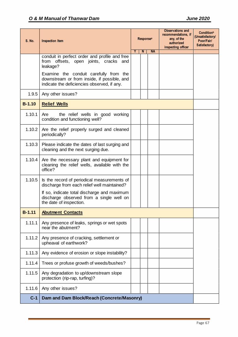
O & M Manual of Thanwar Dam June 2020
Page 67
S. No. Inspection Item Responsea
Observations and recommendations, if
any, of the authorized
inspecting officer
Conditionb
(Unsatisfactory/Poor/Fair/
Satisfactory)
Y N NA
conduit in perfect order and profile and free from offsets, open joints, cracks and leakage?
Examine the conduit carefully from the downstream or from inside, if possible, and indicate the deficiencies observed, if any.
1.9.5 Any other issues?
B-1.10 Relief Wells
1.10.1 Are the relief wells in good working condition and functioning well?
1.10.2 Are the relief properly surged and cleaned periodically?
1.10.3 Please indicate the dates of last surging and cleaning and the next surging due.
1.10.4 Are the necessary plant and equipment for cleaning the relief wells, available with the office?
1.10.5 Is the record of periodical measurements of discharge from each relief well maintained?
If so, indicate total discharge and maximum discharge observed from a single well on the date of inspection.
B-1.11 Abutment Contacts
1.11.1 Any presence of leaks, springs or wet spots near the abutment?
1.11.2 Any presence of cracking, settlement or upheaval of earthwork?
1.11.3 Any evidence of erosion or slope instability?
1.11.4 Trees or profuse growth of weeds/bushes?
1.11.5 Any degradation to up/downstream slope protection (rip-rap, turfing)?
1.11.6 Any other issues?
C-1 Dam and Dam Block/Reach (Concrete/Masonry)
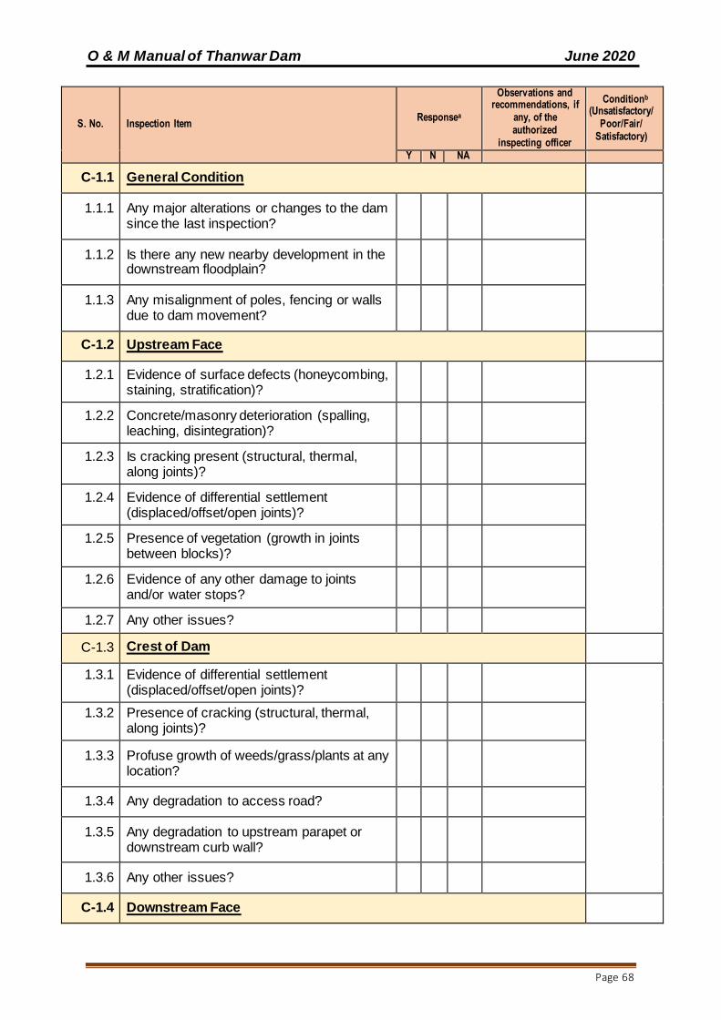
O & M Manual of Thanwar Dam June 2020
Page 68
S. No. Inspection Item Responsea
Observations and recommendations, if
any, of the authorized
inspecting officer
Conditionb
(Unsatisfactory/Poor/Fair/
Satisfactory)
Y N NA
C-1.1 General Condition
1.1.1 Any major alterations or changes to the dam since the last inspection?
1.1.2 Is there any new nearby development in the downstream floodplain?
1.1.3 Any misalignment of poles, fencing or walls due to dam movement?
C-1.2 Upstream Face
1.2.1 Evidence of surface defects (honeycombing, staining, stratification)?
1.2.2 Concrete/masonry deterioration (spalling, leaching, disintegration)?
1.2.3 Is cracking present (structural, thermal, along joints)?
1.2.4 Evidence of differential settlement (displaced/offset/open joints)?
1.2.5 Presence of vegetation (growth in joints between blocks)?
1.2.6 Evidence of any other damage to joints and/or water stops?
1.2.7 Any other issues?
C-1.3 Crest of Dam
1.3.1 Evidence of differential settlement (displaced/offset/open joints)?
1.3.2 Presence of cracking (structural, thermal, along joints)?
1.3.3 Profuse growth of weeds/grass/plants at any location?
1.3.4 Any degradation to access road?
1.3.5 Any degradation to upstream parapet or downstream curb wall?
1.3.6 Any other issues?
C-1.4 Downstream Face
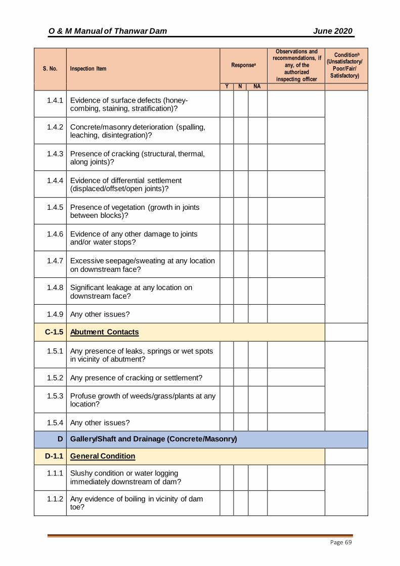
O & M Manual of Thanwar Dam June 2020
Page 69
S. No. Inspection Item Responsea
Observations and recommendations, if
any, of the authorized
inspecting officer
Conditionb
(Unsatisfactory/Poor/Fair/
Satisfactory)
Y N NA
1.4.1 Evidence of surface defects (honey-combing, staining, stratification)?
1.4.2 Concrete/masonry deterioration (spalling, leaching, disintegration)?
1.4.3 Presence of cracking (structural, thermal, along joints)?
1.4.4 Evidence of differential settlement (displaced/offset/open joints)?
1.4.5 Presence of vegetation (growth in joints between blocks)?
1.4.6 Evidence of any other damage to joints and/or water stops?
1.4.7 Excessive seepage/sweating at any location on downstream face?
1.4.8 Significant leakage at any location on downstream face?
1.4.9 Any other issues?
C-1.5 Abutment Contacts
1.5.1 Any presence of leaks, springs or wet spots in vicinity of abutment?
1.5.2 Any presence of cracking or settlement?
1.5.3 Profuse growth of weeds/grass/plants at any location?
1.5.4 Any other issues?
D Gallery/Shaft and Drainage (Concrete/Masonry)
D-1.1 General Condition
1.1.1 Slushy condition or water logging immediately downstream of dam?
1.1.2 Any evidence of boiling in vicinity of dam toe?
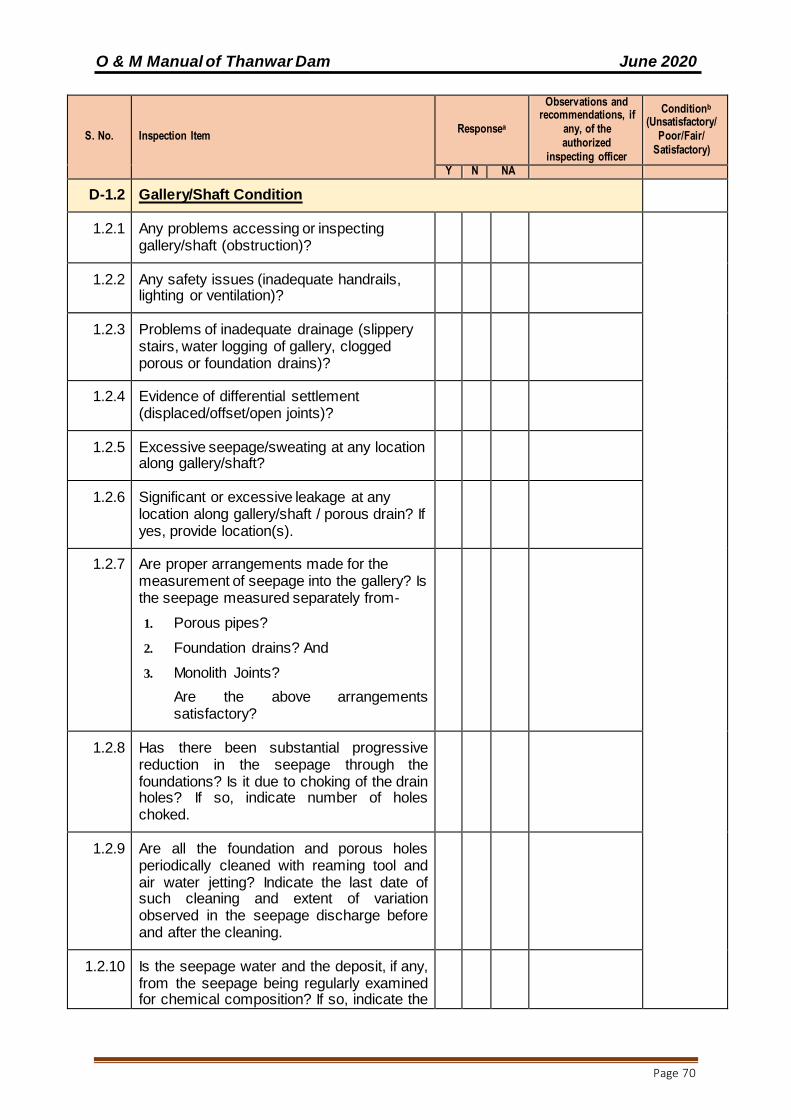
O & M Manual of Thanwar Dam June 2020
Page 70
S. No. Inspection Item Responsea
Observations and recommendations, if
any, of the authorized
inspecting officer
Conditionb
(Unsatisfactory/Poor/Fair/
Satisfactory)
Y N NA
D-1.2 Gallery/Shaft Condition
1.2.1 Any problems accessing or inspecting gallery/shaft (obstruction)?
1.2.2 Any safety issues (inadequate handrails, lighting or ventilation)?
1.2.3 Problems of inadequate drainage (slippery stairs, water logging of gallery, clogged porous or foundation drains)?
1.2.4 Evidence of differential settlement (displaced/offset/open joints)?
1.2.5 Excessive seepage/sweating at any location along gallery/shaft?
1.2.6 Significant or excessive leakage at any location along gallery/shaft / porous drain? If yes, provide location(s).
1.2.7 Are proper arrangements made for the measurement of seepage into the gallery? Is the seepage measured separately from-
1. Porous pipes?
2. Foundation drains? And
3. Monolith Joints?
Are the above arrangements satisfactory?
1.2.8 Has there been substantial progressive reduction in the seepage through the foundations? Is it due to choking of the drain holes? If so, indicate number of holes choked.
1.2.9 Are all the foundation and porous holes periodically cleaned with reaming tool and air water jetting? Indicate the last date of such cleaning and extent of variation observed in the seepage discharge before and after the cleaning.
1.2.10 Is the seepage water and the deposit, if any, from the seepage being regularly examined for chemical composition? If so, indicate the

O & M Manual of Thanwar Dam June 2020
Page 71
S. No. Inspection Item Responsea
Observations and recommendations, if
any, of the authorized
inspecting officer
Conditionb
(Unsatisfactory/Poor/Fair/
Satisfactory)
Y N NA
result and the probable source of dissolved salts, if any.
1.2.11 Are any seepage water springs observed in the downstream area anywhere? If so, indicate the locations and state the physical nature of this seepage. Look out for such seepage spots particularly near the dykes, fault zone etc. Ascertain if chemical testing are made of water samples from such springs for dissolved salts.
1.2.12 Is there any leachate deposition? If yes provide location
1.2.13 Any other issues?
D-1.3 Drain Condition
1.3.1 Is the flow in the drain unusually high or low?
1.3.2 Presence of calcium or other deposits in drain?
1.3.3 Is dewatering pumping station fully operational?
1.3.4 Any problem inspecting pump?
1.3.5 Any obstruction preventing or impairing smooth operation?
1.3.6 Any deterioration of pump and associated equipment?
1.3.7 Is sump well clean and maintained?
1.3.8 Is V-notch before sump well clean and maintained?
1.3.9 Any other evidence of the drain being blocked/having reduced section?
1.3.10 Is the flow in the drain noticeably sporadic/irregular?
1.3.11 Does the drainage water have unusual color (leachate)?
1.3.12 Any other issues?

O & M Manual of Thanwar Dam June 2020
Page 72
S. No. Inspection Item Responsea
Observations and recommendations, if
any, of the authorized
inspecting officer
Conditionb
(Unsatisfactory/Poor/Fair/
Satisfactory)
Y N NA
D-1.4 Body Wall (Masonry/Concrete) of ‘NOF’ Dam and Spillway
1.4.1 What is the total seepage into gallery from the porous pipes in the dam at lake full condition? How does it compare with the seepage when the reservoir was first filled? (For the corresponding water level)
1.4.2 If there has been substantial reduction in this seepage? Ascertain and indicate the probable reasons therefore.
1.4.3 Has there been a tendency for gradual reduction of drainage through pipes and progressive appearance of sweating on the downstream face of the dam?
1.4.4 Has there been considerable leaching from the seepage water and deposition of lime near the seepage exit spots?
1.4.5 Are the samples of the seepage water and reservoir water being regularly tested for reactive and corrosive properties?
1.4.6 Is there excessive seepage, sweating at any locations on the downstream face of the dam?( Examine the monolith or construction joints for such seepage and leaching and indicate the findings)
1.4.7 Is there any swelling or cracking observed on the downstream face especially near the points of concentration of stresses like the toe or locations of abrupt change in geometry of the face of the opening? If so, indicate the details of observations.
1.4.8 Is the pointing on upstream face of the dam in good condition? If not, indicate the nature and extent of deficiency.
1.4.9 Are the registers and graphs showing the periodical measurements of seepage discharge from the porous drains in the gallery and from the downstream face at various lake levels maintained at site?
D 1.5 Waste Weir Bar and Tail Channel
1.5.1 Is the Concrete/masonry spillway bar in

O & M Manual of Thanwar Dam June 2020
Page 73
S. No. Inspection Item Responsea
Observations and recommendations, if
any, of the authorized
inspecting officer
Conditionb
(Unsatisfactory/Poor/Fair/
Satisfactory)
Y N NA
good condition? Is there any leakage through the masonry or from the foundation? If so, what remedial measures are proposed/taken for minimizing the leakage? Is the record of leakage measurement maintained? What is the quantity of Seepage/Leakage on the date of inspection?
1.5.2 Is the coping over the spillway bar in good condition?
1.5.3 Does the upstream and downstream face of waste weir bar need pointing?
1.5.4 Is there any scouring on downstream side of the bar and/or EDA? If so what remedial measures are proposed/taken?
1.5.5 Are there any damages or undermining to guide walls, divide wall and other appurtenant? If so, what remedial measures are proposed/taken?
D 1.6 Structural performance of the ‘NOF’ and ‘OF’ Portions of Dam Foundations
1.6.1 Are there any signs of structural distress noticed in the dam spillway and foundations in the form of-
i. Excessive deflection with respect to permissible deflection at the time of design
ii. Tendency of gradual sliding
iii. Cracking and upheaval or settlement in any part of the body wall or foundations,
iv. Excessive uplift,
v. Excessive seepage and leaching through the body of the dam and the foundation.
1.6.2 Conspicuous weathering of materials or components in any portion of the body wall or the foundations.
E Spillway and Energy Dissipation Structure
E 1.1 Spillway

O & M Manual of Thanwar Dam June 2020
Page 74
S. No. Inspection Item Responsea
Observations and recommendations, if
any, of the authorized
inspecting officer
Conditionb
(Unsatisfactory/Poor/Fair/
Satisfactory)
Y N NA
1.1.1 Any problems inspecting spillway (obstructed access, damaged catwalk)?
1.1.2 Any obstructions in or immediately downstream of the spillway?
1.1.3 Evidence of abrasion, cavitation or scour on glacis (e.g. exposed reinforcement)?
1.1.4 Presence of displaced, offset or open joints?
1.1.5 Presence of cracking (structural, thermal, along joints)?
1.1.6 Evidence of surface defects (honeycombing, staining, stratification)?
1.1.7 Concrete/masonry deterioration (spalling, leaching, disintegration)?
1.1.8 Presence of vegetation (growth in joints between blocks)?
1.1.9 Evidence of any other damage to joints and/or water stops?
1.1.10 Excessive seepage/sweating at any location on spillway glacis?
1.1.11 Significant leakage at any location on spillway glacis?
1.1.12 Any other issues?
E-1.2 Energy Dissipation Structure
1.2.1 Any problems inspecting energy dissipation structure?
1.2.2 Any obstructions in or immediately downstream of dissipation structure?
1.2.3 Evidence of abrasion, cavitation or scour on dissipation structure?
1.2.4 Presence of displaced, offset or open joints?
1.2.5 Presence of cracking (structural, thermal, along joints)?
1.2.6 Evidence of surface defects (honeycombing,

O & M Manual of Thanwar Dam June 2020
Page 75
S. No. Inspection Item Responsea
Observations and recommendations, if
any, of the authorized
inspecting officer
Conditionb
(Unsatisfactory/Poor/Fair/
Satisfactory)
Y N NA
staining, stratification)?
1.2.7 Concrete/masonry deterioration (spalling, leaching, disintegration)?
1.2.8 Presence of vegetation (growth in joints between blocks)?
1.2.9 Evidence of any other damage to joints?
1.2.10 Any problems with under-drainage (blockage of open drain holes)?
1.2.11 Can the tail pond be drained easily for inspection of the stilling basin or bucket? If not, what are the alternatives available for dewatering? Please ascertain and indicate the last event of inspection of stilling basin (or bucket).
1.2.12 From the examination of the levels and contour plans and reference marks in tail channel; ascertain if there is progressive erosion and retrogression in the tail channel. If so, indicate the extent and location of such erosion with reference to the various components of dam, spillway, outlet, power house etc.
1.2.13 Is the concrete surface of the stilling basin and apron (or bucket) in good condition? Are there any indications of pitting, cracking, spalling or wearing of the surface of bedding concrete? If so, please give details of the nature and extent of the damage.
1.2.13 Is there any indication of abrasion and cavitation damage (pitting of concrete) especially at friction blocks, chute blocks and slotted roller teeth, the surface near the lower tangent point and the end sill? If so, please give the details of nature and extent of damage.
1.2.14 Is the under drainage of the stilling basin (or bucket) satisfactory? Are all the open drain holes clear and functioning well?

O & M Manual of Thanwar Dam June 2020
Page 76
S. No. Inspection Item Responsea
Observations and recommendations, if
any, of the authorized
inspecting officer
Conditionb
(Unsatisfactory/Poor/Fair/
Satisfactory)
Y N NA
1.2.15 Any other issues?
F Intake/Outlet and Water Conveyance Structure
F-1.1 Intake/Outlet Structure
1.1.1 Any problems inspecting intake/outlet structure (obstructed/unsafe access)?
1.1.2 Any obstructions in, upstream or downstream of intake/outlet structure?
1.1.3 Evidence of abrasion, cavitation or scour on intake/outlet structure?
1.1.4 Any evidence of structural distress (displaced/offset/open joints, cracking)?
1.1.5 Any evidence of surface defects and/or concrete/masonry deterioration?
1.1.6 Any other issues?
F-1.2 Water Conveyance Structure
1.2.1 Any problems inspecting intake/outlet structure (obstructed/unsafe access)?
1.2.2 Any obstructions in, upstream or downstream of water conveyance structure?
1.2.3 Evidence of abrasion, cavitation or scour on structure?
1.2.4 Any evidence of structural distress (displaced/offset/open joints, cracking)?
1.2.5 Any evidence of surface defects and/or material deterioration?
1.2.6 Any evidence of seepage or leakage from water conveyance structure?
1.2.7 Any other issues?
G-1 Hydro-Mechanical Component and Pump
G-1.1 Spillway Gates (Radial gates, Vertical lift gates, Automatic gates)
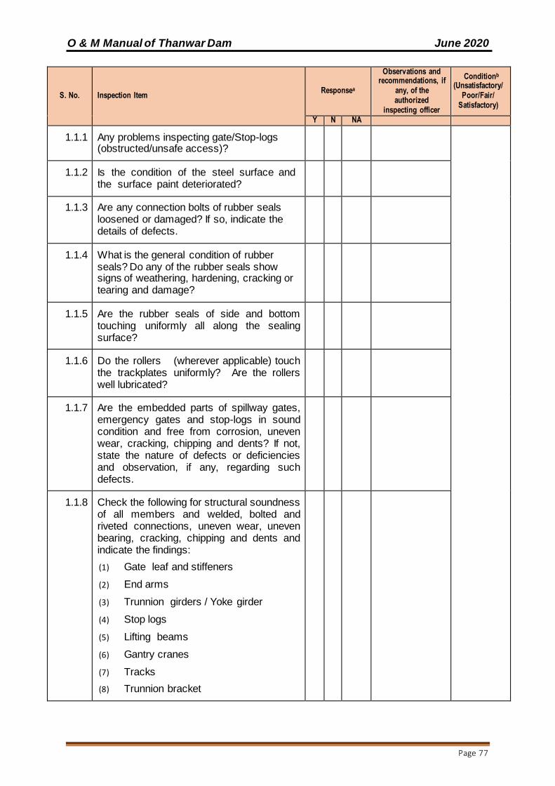
O & M Manual of Thanwar Dam June 2020
Page 77
S. No. Inspection Item Responsea
Observations and recommendations, if
any, of the authorized
inspecting officer
Conditionb
(Unsatisfactory/Poor/Fair/
Satisfactory)
Y N NA
1.1.1 Any problems inspecting gate/Stop-logs (obstructed/unsafe access)?
1.1.2 Is the condition of the steel surface and the surface paint deteriorated?
1.1.3 Are any connection bolts of rubber seals loosened or damaged? If so, indicate the details of defects.
1.1.4 What is the general condition of rubber seals? Do any of the rubber seals show signs of weathering, hardening, cracking or tearing and damage?
1.1.5 Are the rubber seals of side and bottom touching uniformly all along the sealing surface?
1.1.6 Do the rollers (wherever applicable) touch the trackplates uniformly? Are the rollers well lubricated?
1.1.7 Are the embedded parts of spillway gates, emergency gates and stop-logs in sound condition and free from corrosion, uneven wear, cracking, chipping and dents? If not, state the nature of defects or deficiencies and observation, if any, regarding such defects.
1.1.8 Check the following for structural soundness of all members and welded, bolted and riveted connections, uneven wear, uneven bearing, cracking, chipping and dents and indicate the findings:
(1) Gate leaf and stiffeners
(2) End arms
(3) Trunnion girders / Yoke girder
(4) Stop logs
(5) Lifting beams
(6) Gantry cranes
(7) Tracks
(8) Trunnion bracket
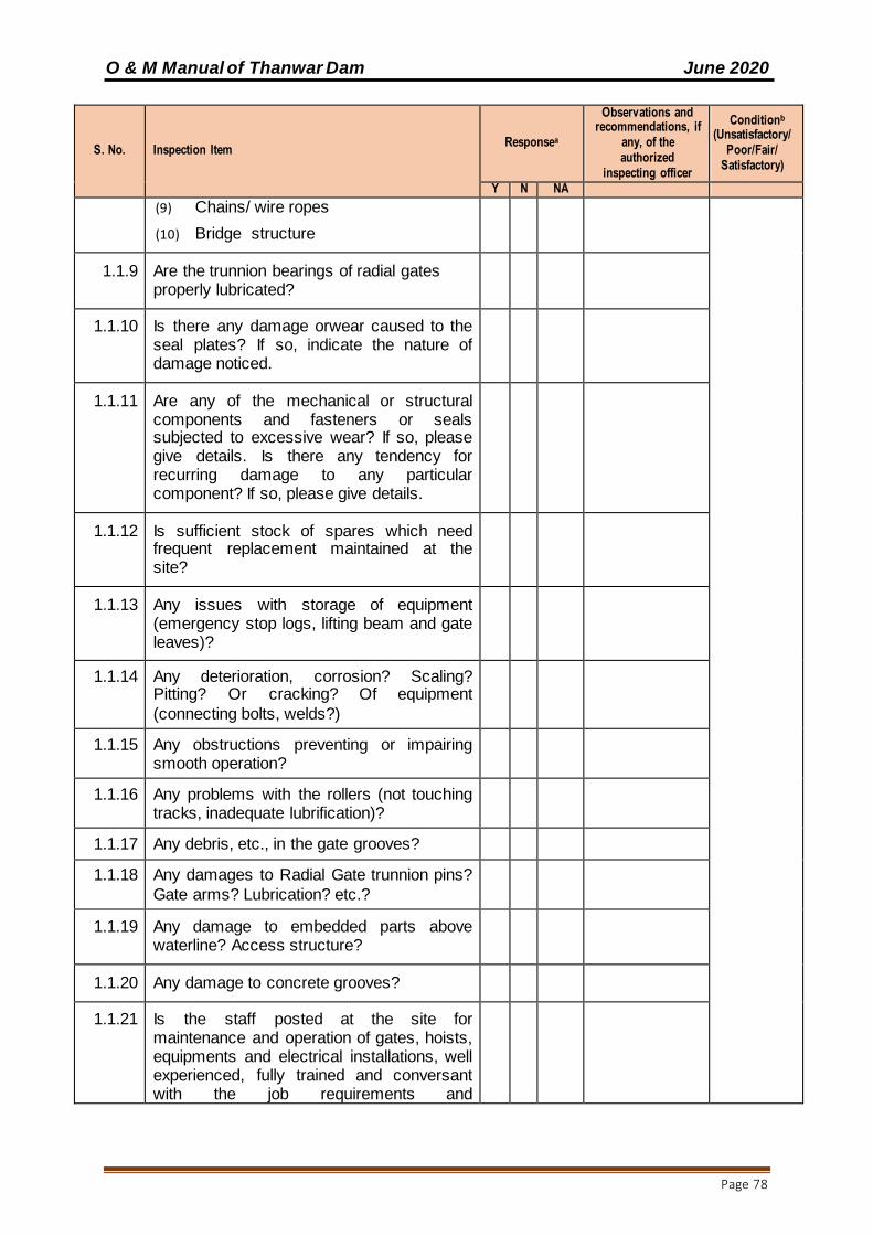
O & M Manual of Thanwar Dam June 2020
Page 78
S. No. Inspection Item Responsea
Observations and recommendations, if
any, of the authorized
inspecting officer
Conditionb
(Unsatisfactory/Poor/Fair/
Satisfactory)
Y N NA
(9) Chains/ wire ropes
(10) Bridge structure
1.1.9 Are the trunnion bearings of radial gates properly lubricated?
1.1.10 Is there any damage orwear caused to the seal plates? If so, indicate the nature of damage noticed.
1.1.11 Are any of the mechanical or structural components and fasteners or seals subjected to excessive wear? If so, please give details. Is there any tendency for recurring damage to any particular component? If so, please give details.
1.1.12 Is sufficient stock of spares which need frequent replacement maintained at the site?
1.1.13 Any issues with storage of equipment (emergency stop logs, lifting beam and gate leaves)?
1.1.14 Any deterioration, corrosion? Scaling? Pitting? Or cracking? Of equipment
(connecting bolts, welds?)
1.1.15 Any obstructions preventing or impairing smooth operation?
1.1.16 Any problems with the rollers (not touching tracks, inadequate lubrification)?
1.1.17 Any debris, etc., in the gate grooves?
1.1.18 Any damages to Radial Gate trunnion pins?
Gate arms? Lubrication? etc.?
1.1.19 Any damage to embedded parts above waterline? Access structure?
1.1.20 Any damage to concrete grooves?
1.1.21 Is the staff posted at the site for maintenance and operation of gates, hoists, equipments and electrical installations, well experienced, fully trained and conversant with the job requirements and

O & M Manual of Thanwar Dam June 2020
Page 79
S. No. Inspection Item Responsea
Observations and recommendations, if
any, of the authorized
inspecting officer
Conditionb
(Unsatisfactory/Poor/Fair/
Satisfactory)
Y N NA
responsibilities?
1.1.22 Are the following documents maintained at the respective location of all the units?
(1) Maintenance schedules specifying each operation, its frequency and ‘due’ and’ done’ dates.
(2) Operating instructions with ‘dos’ and ‘don’t’ for all operational units.
1.1.23 Are the trunnion hub and the brackets well maintained?
1.1.24 Are the trunnions likely to get submerged during actual working of the spillway? If so, ascertain the causes for the same and specify. Please enquire for occurrence of such events, if any.
1.1.25 Are all the nuts of connecting bolts and anchorages properly tightened?
1.1.26 Any other issues?
G-1.2 Hoists, Cranes and Operating Mechanisms
1.2.1 Are the hoists working satisfactorily?
1.2.2 Any problems inspecting hoist/crane/operating mechanism?
1.2.3 Is sufficient stock of spares which need frequent replacement maintained at the site?
1.2.4 Is the full length of the chains or wire rope of the hoist in sound condition and free from broken strands?
1.2.5 Is the electrical wiring in sound condition?
1.2.6 Is the alternative power system for gate operation working properly?
1.2.7 Is the alternate hand operation system of hoist working
1.2.8 Any deterioration of equipment (connecting

O & M Manual of Thanwar Dam June 2020
Page 80
S. No. Inspection Item Responsea
Observations and recommendations, if
any, of the authorized
inspecting officer
Conditionb
(Unsatisfactory/Poor/Fair/
Satisfactory)
Y N NA
bolts, welds, surface, paint work?)
1.2.9 Any wear or damage to wire cables and other moving parts?
1.2.10 Any obstructions preventing or impairing smooth operation?
1.2.11 Any health and safety concerns (e.g. lack of "danger" sign during maintenance)?
1.2.12 Any other issues?
G 1.3. Spillway Bridge, Hoist Bridge, Trunnion Level Bridge Catwalks
1.3.1 Are the decking, girders and structural supports of spillway bridge, hoist bridge, trunnion level bridge and catwalks structurally sound?
1.3.2 Is the chequered platform of the bridge structurally sound and safe?
1.3.3 Is there satisfactory arrangement to prevent unauthorized entry into the control structures and bridges?
1.3.4 Are the structural members and joints sound and free from corrosion?
1.3.5 When were the steel components painted last?
1.3.6 Is the surface of steel work and paints satisfactory?
1.3.7 Is the parapet or railing over the bridges sound, safe and painted?
1.3.8 Is the walkway properly encored to the piers?
1.3.9 Are the track rails for gantry cranes structurally sound and intact?
G-1.4 Valves

O & M Manual of Thanwar Dam June 2020
Page 81
S. No. Inspection Item Responsea
Observations and recommendations, if
any, of the authorized
inspecting officer
Conditionb
(Unsatisfactory/Poor/Fair/
Satisfactory)
Y N NA
1.4.1 Any problems inspecting valve?
1.4.2 Any obstructions preventing or impairing smooth operation?
1.4.3 Any deterioration of valve and associated equipment?
1.4.4 Any other issues?
G-1.5 Walls: Guide walls/Divide walls/Junction walls/Return walls/Spray walls etc. (Strike out whichever is not applicable)
1.5.1 Are all the locations of such wall accessible for inspection, maintenance and repairs?
1.5.2 Is the drainage of back sides of the walls (wherever applicable) from the weep holes satisfactory? If not, indicate the nature of deficiencies.
1.5.3 Is there any tendency for the water to undercut the ends of the walls?
1.5.4 Is there any foundation erosion or scour noticed in the vicinity of such walls? If so, give the details of nature and extent of such damage.
1.5.5 Is there any surface erosion/damage caused, to face or body of such walls?
1.5.6 Do any of the walls show symptoms of unusual settlement, developments of cracks and tilting? If so, give details of the defects noticed.
1.5.7 Is there any damage to guide bunds? If so, give details of the damage.
G-1.6 EndWeir
1.6.1 Is it accessible?
1.6.2 Is there any erosion, pitting or spalling of the concrete or masonry surface?
If so, give details

O & M Manual of Thanwar Dam June 2020
Page 82
S. No. Inspection Item Responsea
Observations and recommendations, if
any, of the authorized
inspecting officer
Conditionb
(Unsatisfactory/Poor/Fair/
Satisfactory)
Y N NA
1.6.3 Is there any scour noticed on the immediate downstream of such weir? If so, give details of location and extent of such damage.
G-1.7 HydraulicPerformanceofEnergyDissipationArrangements
1.7.1 Do the flow conditions in the stilling basin (or bucket) have a tendency to draw material into the bucket and causes its churning and abrasion damage to the surface of buckets baffle blocks, apron and end sill?
Is the hydraulic performance in agreement with the results of model studies? (wherever applicable)
Ascertain the performance from observed tail water rating curves and deficient observation, if any, such as sweep outs and excessive erosion under plunge pools and locations of secondary rollers and retrogression.
G-1.8 Trash Racks
1.8.1 Is the trash rack fixed or movable?
1.8.2 What is the mode of cleaning? Is it manual or by TRCM?
1.8.3 Is the welding work on Trash Rack in sound health?
1.8.4 Any problems inspecting trash rack?
1.8.5 Problems of excessive debris and/or
inadequate cleaning?
1.8.6 Any deterioration of trash rack (rust,
corrosion, and damaged blades)?
1.8.7 Any other issues?
G-1.9 Trash Rack Cleaning Machines
1.9.1 Any problems inspecting trash rack cleaning machine?
1.9.2 Missing or inadequate spare parts (particularly requiring regular replacement)?
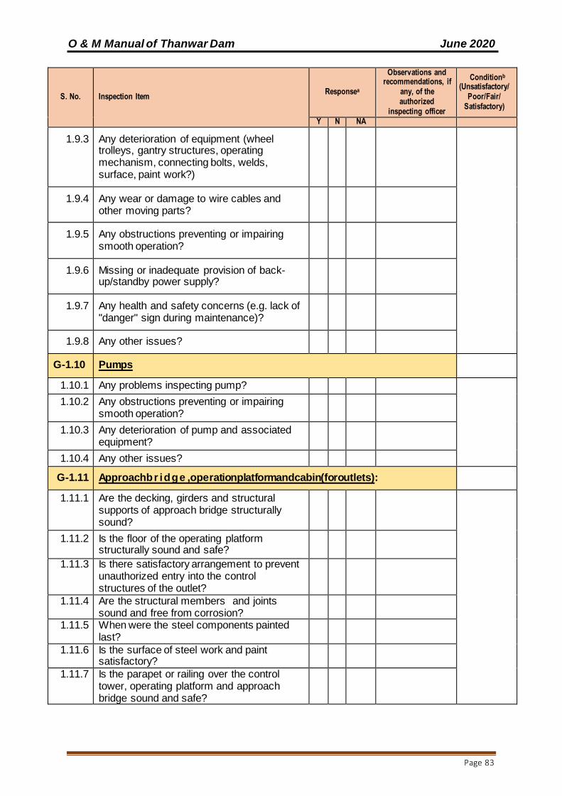
O & M Manual of Thanwar Dam June 2020
Page 83
S. No. Inspection Item Responsea
Observations and recommendations, if
any, of the authorized
inspecting officer
Conditionb
(Unsatisfactory/Poor/Fair/
Satisfactory)
Y N NA
1.9.3 Any deterioration of equipment (wheel trolleys, gantry structures, operating mechanism, connecting bolts, welds, surface, paint work?)
1.9.4 Any wear or damage to wire cables and other moving parts?
1.9.5 Any obstructions preventing or impairing smooth operation?
1.9.6 Missing or inadequate provision of back-up/standby power supply?
1.9.7 Any health and safety concerns (e.g. lack of "danger" sign during maintenance)?
1.9.8 Any other issues?
G-1.10 Pumps
1.10.1 Any problems inspecting pump?
1.10.2 Any obstructions preventing or impairing smooth operation?
1.10.3 Any deterioration of pump and associated equipment?
1.10.4 Any other issues?
G-1.11 Approachbr idge ,operationplatformandcabin(foroutlets):
1.11.1 Are the decking, girders and structural supports of approach bridge structurally sound?
1.11.2 Is the floor of the operating platform structurally sound and safe?
1.11.3 Is there satisfactory arrangement to prevent unauthorized entry into the control structures of the outlet?
1.11.4 Are the structural members and joints sound and free from corrosion?
1.11.5 When were the steel components painted last?
1.11.6 Is the surface of steel work and paint satisfactory?
1.11.7 Is the parapet or railing over the control tower, operating platform and approach bridge sound and safe?
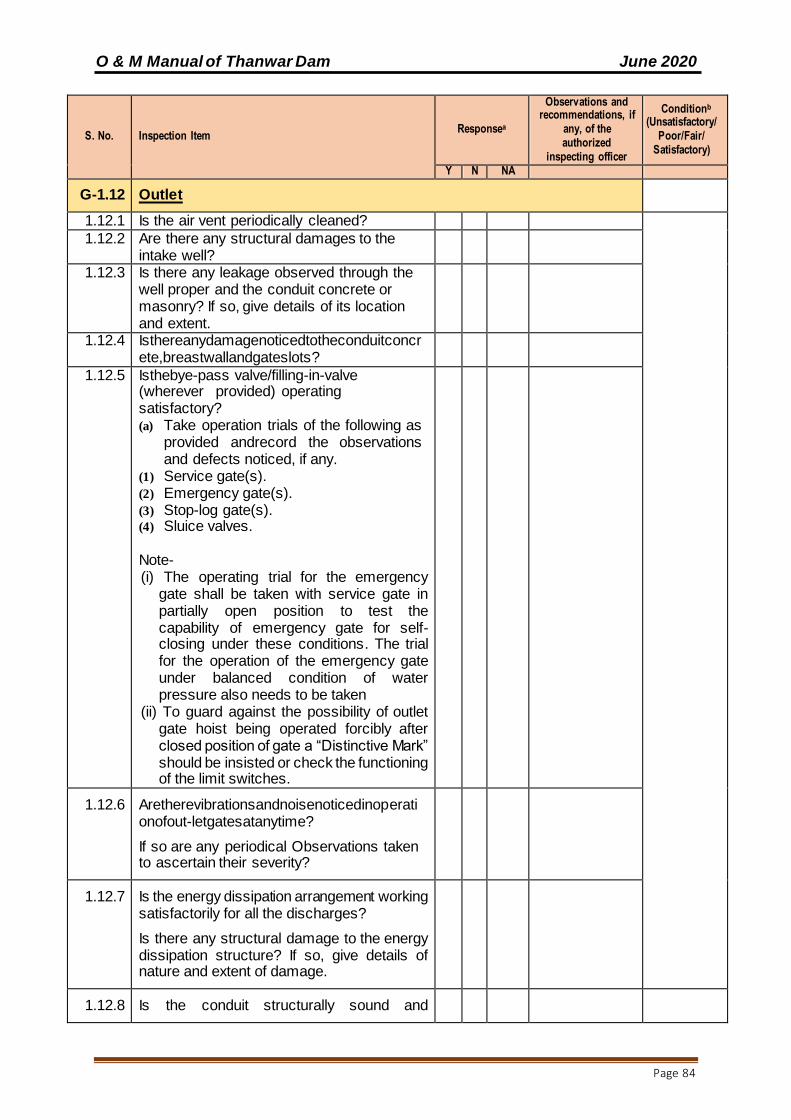
O & M Manual of Thanwar Dam June 2020
Page 84
S. No. Inspection Item Responsea
Observations and recommendations, if
any, of the authorized
inspecting officer
Conditionb
(Unsatisfactory/Poor/Fair/
Satisfactory)
Y N NA
G-1.12 Outlet
1.12.1 Is the air vent periodically cleaned?
1.12.2 Are there any structural damages to the intake well?
1.12.3 Is there any leakage observed through the well proper and the conduit concrete or masonry? If so, give details of its location and extent.
1.12.4 Isthereanydamagenoticedtotheconduitconcrete,breastwallandgateslots?
1.12.5 Isthebye-pass valve/filling-in-valve (wherever provided) operating satisfactory? (a) Take operation trials of the following as
provided andrecord the observations and defects noticed, if any.
(1) Service gate(s). (2) Emergency gate(s). (3) Stop-log gate(s). (4) Sluice valves.
Note- (i) The operating trial for the emergency
gate shall be taken with service gate in partially open position to test the capability of emergency gate for self-closing under these conditions. The trial for the operation of the emergency gate under balanced condition of water pressure also needs to be taken
(ii) To guard against the possibility of outlet gate hoist being operated forcibly after closed position of gate a “Distinctive Mark” should be insisted or check the functioning of the limit switches.
1.12.6 Aretherevibrationsandnoisenoticedinoperationofout-letgatesatanytime?
If so are any periodical Observations taken to ascertain their severity?
1.12.7 Is the energy dissipation arrangement working satisfactorily for all the discharges?
Is there any structural damage to the energy dissipation structure? If so, give details of nature and extent of damage.
1.12.8 Is the conduit structurally sound and
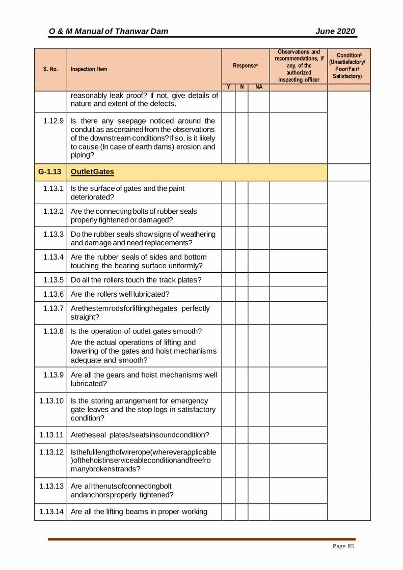
O & M Manual of Thanwar Dam June 2020
Page 85
S. No. Inspection Item Responsea
Observations and recommendations, if
any, of the authorized
inspecting officer
Conditionb
(Unsatisfactory/Poor/Fair/
Satisfactory)
Y N NA
reasonably leak proof? If not, give details of nature and extent of the defects.
1.12.9 Is there any seepage noticed around the conduit as ascertained from the observations of the downstream conditions? If so, is it likely to cause (In case of earth dams) erosion and piping?
G-1.13 OutletGates
1.13.1 Is the surface of gates and the paint deteriorated?
1.13.2 Are the connecting bolts of rubber seals properly tightened or damaged?
1.13.3 Do the rubber seals show signs of weathering and damage and need replacements?
1.13.4 Are the rubber seals of sides and bottom touching the bearing surface uniformly?
1.13.5 Do all the rollers touch the track plates?
1.13.6 Are the rollers well lubricated?
1.13.7 Arethestemrodsforliftingthegates perfectly straight?
1.13.8 Is the operation of outlet gates smooth?
Are the actual operations of lifting and lowering of the gates and hoist mechanisms
adequate and smooth?
1.13.9 Are all the gears and hoist mechanisms well lubricated?
1.13.10 Is the storing arrangement for emergency gate leaves and the stop logs in satisfactory condition?
1.13.11 Aretheseal plates/seatsinsoundcondition?
1.13.12 Isthefulllengthofwirerope(whereverapplicable)ofthehoistinserviceableconditionandfreefromanybrokenstrands?
1.13.13 Are allthenutsofconnectingbolt andanchorsproperly tightened?
1.13.14 Are all the lifting beams in proper working

O & M Manual of Thanwar Dam June 2020
Page 86
S. No. Inspection Item Responsea
Observations and recommendations, if
any, of the authorized
inspecting officer
Conditionb
(Unsatisfactory/Poor/Fair/
Satisfactory)
Y N NA
order and in leveled condition? If not ascertain the nature and extent of problems. Do any of the mechanical or structural parts of the gate, fasteners of hoist show signs of excessive wear? If so, please give details.
1.13.15 Is there any tendency for recurring damage to any particular component or components? If so, please give details.
1.13.16 Is sufficient stock of spares, which need frequent replacement, maintained at the site?
G-1.14 River Outlet/River Sluice
1.14.1 Is the overall condition of river outlet works/river sluices satisfactory?
Is the operation of the gate (Service/Emergency/Stop-log) satisfactory as ascertained by taking operating trial? If not, indicate the defects noticed.
1.14.2 Are the trash racks (wherever provided) cleaned before monsoon?
1.14.3 Is there excessive silting on the upstream of the sluice?
1.14.4 When the gates were last opened for de-silting, etc.?
1.14.5 Please indicate the approximate quantity of the leakage through the gates, if any.
1.14.6 Is there any seepage or leakage through the conduit surface?
1.14.7 Is there any damage to the upstream and downstream convergence of the conduit?
1.14.8 Is the condition of energy dissipation arrangement satisfactory?
If not, indicate nature and extent of damage. Is there any retrogression noticed in the downstream channel? If so, give details of
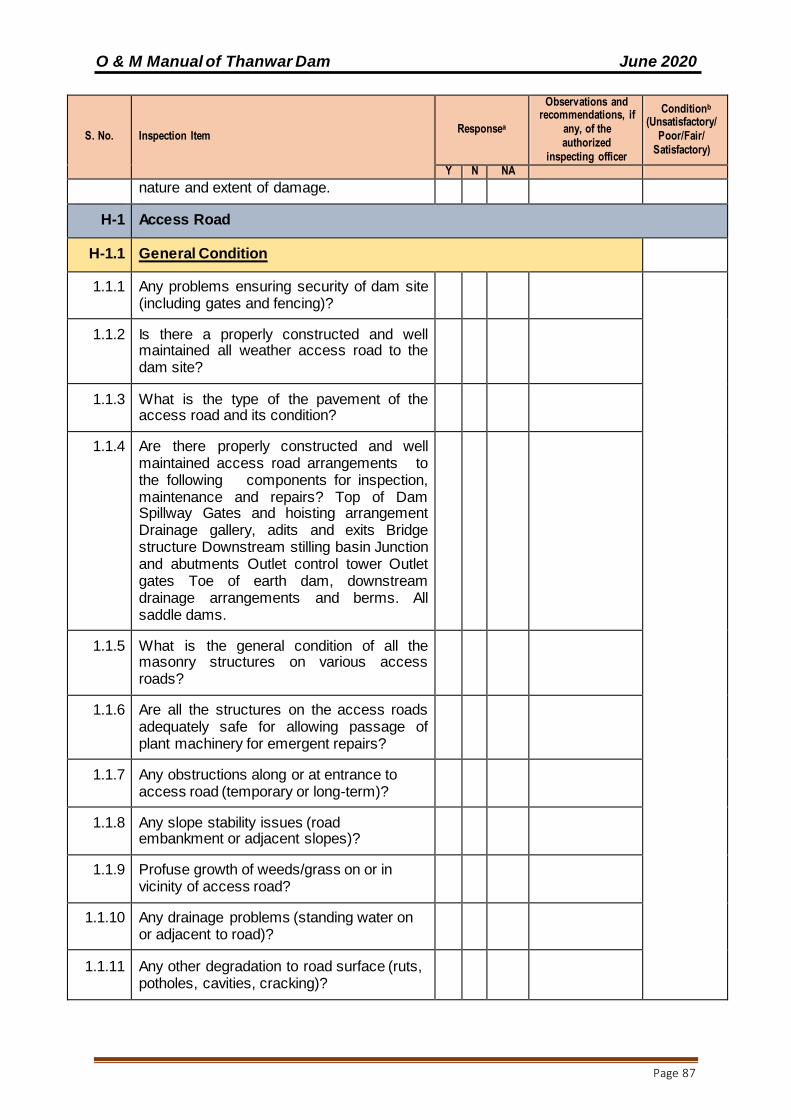
O & M Manual of Thanwar Dam June 2020
Page 87
S. No. Inspection Item Responsea
Observations and recommendations, if
any, of the authorized
inspecting officer
Conditionb
(Unsatisfactory/Poor/Fair/
Satisfactory)
Y N NA
nature and extent of damage.
H-1 Access Road
H-1.1 General Condition
1.1.1 Any problems ensuring security of dam site (including gates and fencing)?
1.1.2 Is there a properly constructed and well maintained all weather access road to the dam site?
1.1.3 What is the type of the pavement of the access road and its condition?
1.1.4 Are there properly constructed and well maintained access road arrangements to the following components for inspection, maintenance and repairs? Top of Dam Spillway Gates and hoisting arrangement Drainage gallery, adits and exits Bridge structure Downstream stilling basin Junction and abutments Outlet control tower Outlet gates Toe of earth dam, downstream drainage arrangements and berms. All saddle dams.
1.1.5 What is the general condition of all the masonry structures on various access roads?
1.1.6 Are all the structures on the access roads adequately safe for allowing passage of plant machinery for emergent repairs?
1.1.7 Any obstructions along or at entrance to access road (temporary or long-term)?
1.1.8 Any slope stability issues (road embankment or adjacent slopes)?
1.1.9 Profuse growth of weeds/grass on or in vicinity of access road?
1.1.10 Any drainage problems (standing water on or adjacent to road)?
1.1.11 Any other degradation to road surface (ruts, potholes, cavities, cracking)?

O & M Manual of Thanwar Dam June 2020
Page 88
S. No. Inspection Item Responsea
Observations and recommendations, if
any, of the authorized
inspecting officer
Conditionb
(Unsatisfactory/Poor/Fair/
Satisfactory)
Y N NA
1.1.12 Any other issues?
I-1 Instrumentation
I-1.1 General Condition
1.1.1 Are all the instruments installed accessible? (Attach separate list).
Are all the locations properly lighted, ventilated and adequately protected from
possibilities of damage?
As per Appendix-I
1.1.2 Any problems inspecting instrument (obstructed/unsafe access)?
1.1.3 Is the instrument vulnerable to damage or theft (inadequate protection)?
1.1.4 Any problems ensuring correct functioning
of instrument (lighting, ventilation)?
1.1.5 Any evidence of degradation to condition of
instrument (rusting, vandalism)?
1.1.6 Are all the instruments in working order? Ascertain the cases of instruments going out
of order and indicate.
1.1.7 Are all the registers of observations posted up-to-date? Please take test observations and initial the register.
1.1.8 Are all the plotting of the instrumentation
data completed up-to-date?
Are sufficient stocks of spares, gauges, master gauges, and stationary items etc., maintained at the site for uninterrupted data
collection?
1.1.9 Operator or public safety issues?
1.1.10 Any other issues?
I-1.2 CommunicationFacilities
1.2.1 Are following facilities available at dam site?
(1) Wireless Telephone /
mobile/Fax/Internet.
1.2.2 Any other issue (please indicate part, location, etc., as necessary)
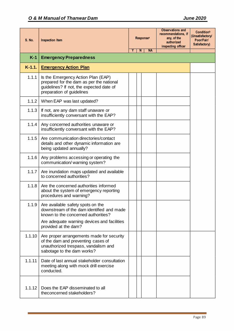
O & M Manual of Thanwar Dam June 2020
Page 89
S. No. Inspection Item Responsea
Observations and recommendations, if
any, of the authorized
inspecting officer
Conditionb
(Unsatisfactory/Poor/Fair/
Satisfactory)
Y N NA
K-1 Emergency Preparedness
K-1.1. Emergency Action Plan
1.1.1 Is the Emergency Action Plan (EAP) prepared for the dam as per the national guidelines? If not, the expected date of preparation of guidelines
1.1.2 When EAP was last updated?
1.1.3 If not, are any dam staff unaware or insufficiently conversant with the EAP?
1.1.4 Any concerned authorities unaware or insufficiently conversant with the EAP?
1.1.5 Are communication directories/contact details and other dynamic information are being updated annually?
1.1.6 Any problems accessing or operating the communication/ warning system?
1.1.7 Are inundation maps updated and available to concerned authorities?
1.1.8 Are the concerned authorities informed about the system of emergency reporting procedures and warning?
1.1.9 Are available safety spots on the downstream of the dam identified and made known to the concerned authorities?
Are adequate warning devices and facilities provided at the dam?
1.1.10 Are proper arrangements made for security of the dam and preventing cases of unauthorized trespass, vandalism and sabotage to the dam works?
1.1.11 Date of last annual stakeholder consultation meeting along with mock drill exercise conducted.
1.1.12
Does the EAP disseminated to all theconcerned stakeholders?

O & M Manual of Thanwar Dam June 2020
Page 90
S. No. Inspection Item Responsea
Observations and recommendations, if
any, of the authorized
inspecting officer
Conditionb
(Unsatisfactory/Poor/Fair/
Satisfactory)
Y N NA
1.1.13 Any other issues?
K-1.2 Inspection of Records
1.2.1 Whetherfollowing Dam Safety Documents areprepared and approved by the competent authority?
I. As Built Drawings
II. EAP
III. Completion Report
IV. DataBook
V. Oand M Manual
1.2.2 Are the relevant documents reviewed and updated from time to time?
1.2.3 Are all the members of the maintenance staff adequately trained and fully conversant with their responsibilities concerning.
(a) Designer’s Operation Criteria.
(b) Standing Operating Procedures.
(c) Maintenance and Vigilance Procedures of the dam.
(d) Maintenance and operation of all control equipments.
(e) Reservoir Operation Schedules, Gate Operation Schedule
(f) Maintenance and Operation of all instruments.
(g) Identification of signs of deficient behaviour.
(h) Reporting Procedures of emergency situations.
(i) Emergency repairs

O & M Manual of Thanwar Dam June 2020
Page 91
L-1.1 Inspection Photographs
1.1.1 Information to be furnished as per Annexure
– II
Respond either yes (Y), no (N) or not applicable (NA).
Condition: Please rate the condition as either Satisfactory, Fair, Poor or
Unsatisfactory as described below:
1. Satisfactory - No existing or potential dam safety deficiencies are
recognized. Acceptable performance is expected under all loading
conditions (static, hydrologic, seismic) in accordance with the applicable
regulatory criteria or tolerable risk guidelines.
2. Fair - No existing dam safety deficiencies are recognized for normal
loading conditions. Rare or extreme hydrologic and/or seismic events may
result in a dam safety deficiency. Risk may be in the range to take further
action.
3. Poor - A dam safety deficiency is recognized for loading conditions which
may realistically occur. Remedial action is necessary. Poor may also be
used when uncertainties exist as to critical analysis parameters which
identify a potential dam safety deficiency. Further investigations and
studies are necessary.
4. Unsatisfactory - A dam safety deficiency is recognized that requires
immediate or emergency remedial action for problem resolution.
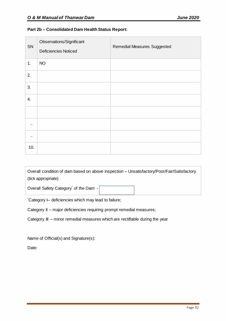
O & M Manual of Thanwar Dam June 2020
Page 92
Part 2b – Consolidated Dam Health Status Report:
SN Observations/Significant
Deficiencies Noticed Remedial Measures Suggested
1. NO
2.
3.
4.
..
..
10.
Overall condition of dam based on above inspection – Unsatisfactory/Poor/Fair/Satisfactory
(tick appropriate)
Overall Safety Category* of the Dam -
*Category I– deficiencies which may lead to failure;
Category II – major deficiencies requiring prompt remedial measures;
Category III – minor remedial measures which are rectifiable during the year
Name of Official(s) and Signature(s):
Date:
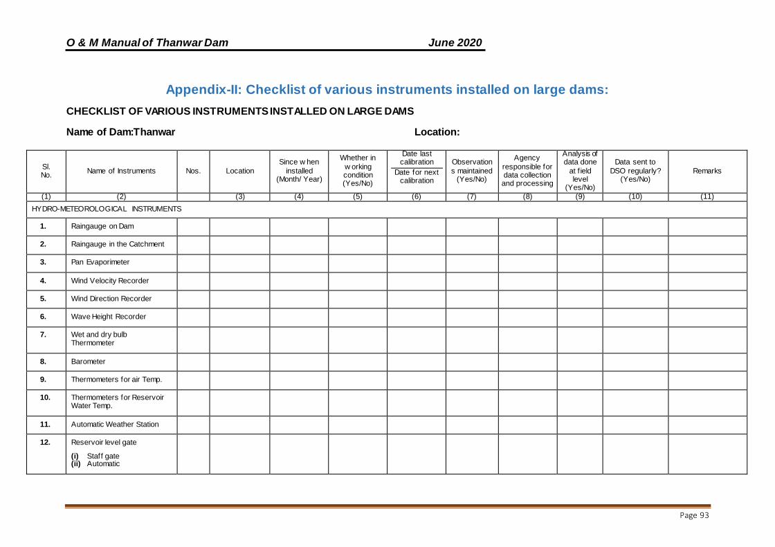
O & M Manual of Thanwar Dam June 2020
Page 93
Appendix-II: Checklist of various instruments installed on large dams:
CHECKLIST OF VARIOUS INSTRUMENTS INSTALLED ON LARGE DAMS
Name of Dam:Thanwar Location:
Sl. No.
Name of Instruments Nos. Location
Since w hen
installed (Month/ Year)
Whether in
w orking condition (Yes/No)
Date last calibration
Date for next calibration
Observation
s maintained (Yes/No)
Agency
responsible for data collection and processing
Analysis of data done
at f ield level
(Yes/No)
Data sent to
DSO regularly? (Yes/No)
Remarks
(1) (2) (3) (4) (5) (6) (7) (8) (9) (10) (11)
HYDRO-METEOROLOGICAL INSTRUMENTS
1. Raingauge on Dam
2. Raingauge in the Catchment
3. Pan Evaporimeter
4. Wind Velocity Recorder
5. Wind Direction Recorder
6. Wave Height Recorder
7. Wet and dry bulb Thermometer
8. Barometer
9. Thermometers for air Temp.
10. Thermometers for Reservoir Water Temp.
11. Automatic Weather Station
12. Reservoir level gate
(i) Staff gate (ii) Automatic
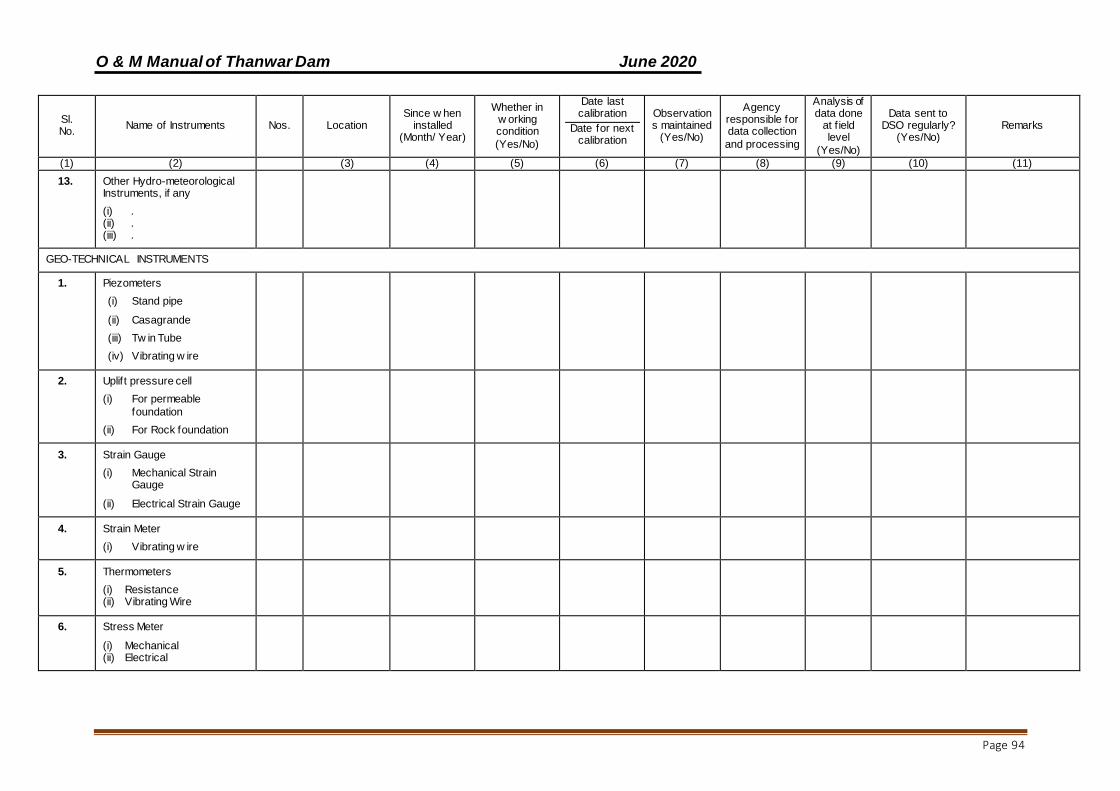
O & M Manual of Thanwar Dam June 2020
Page 94
Sl. No.
Name of Instruments Nos. Location Since w hen
installed (Month/ Year)
Whether in w orking condition
(Yes/No)
Date last calibration
Date for next calibration
Observations maintained
(Yes/No)
Agency responsible for data collection
and processing
Analysis of data done
at f ield level
(Yes/No)
Data sent to DSO regularly?
(Yes/No) Remarks
(1) (2) (3) (4) (5) (6) (7) (8) (9) (10) (11)
13. Other Hydro-meteorological Instruments, if any
(i) . (ii) . (iii) .
GEO-TECHNICAL INSTRUMENTS
1. Piezometers
(i) Stand pipe
(ii) Casagrande
(iii) Tw in Tube
(iv) Vibrating w ire
2. Uplift pressure cell
(i) For permeable
foundation
(ii) For Rock foundation
3. Strain Gauge
(i) Mechanical Strain Gauge
(ii) Electrical Strain Gauge
4. Strain Meter
(i) Vibrating w ire
5. Thermometers
(i) Resistance (ii) Vibrating Wire
6. Stress Meter
(i) Mechanical (ii) Electrical
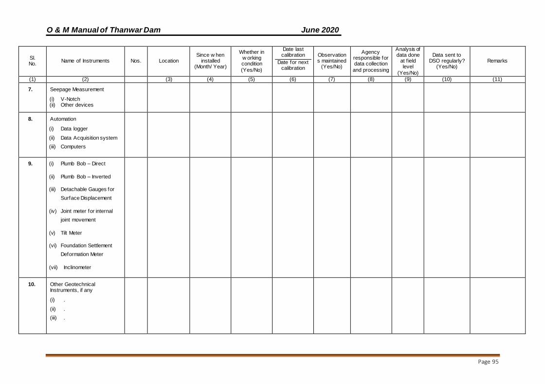
O & M Manual of Thanwar Dam June 2020
Page 95
Sl. No.
Name of Instruments Nos. Location Since w hen
installed (Month/ Year)
Whether in w orking condition
(Yes/No)
Date last calibration
Date for next calibration
Observations maintained
(Yes/No)
Agency responsible for data collection
and processing
Analysis of data done
at f ield level
(Yes/No)
Data sent to DSO regularly?
(Yes/No) Remarks
(1) (2) (3) (4) (5) (6) (7) (8) (9) (10) (11)
7. Seepage Measurement
(i) V-Notch (ii) Other devices
8. Automation
(i) Data logger
(ii) Data Acquisition system
(iii) Computers
9. (i) Plumb Bob – Direct
(ii) Plumb Bob – Inverted
(iii) Detachable Gauges for
Surface Displacement
(iv) Joint meter for internal
joint movement
(v) Tilt Meter
(vi) Foundation Settlement
Deformation Meter
(vii) Inclinometer
10. Other Geotechnical Instruments, if any
(i) .
(ii) .
(iii) .
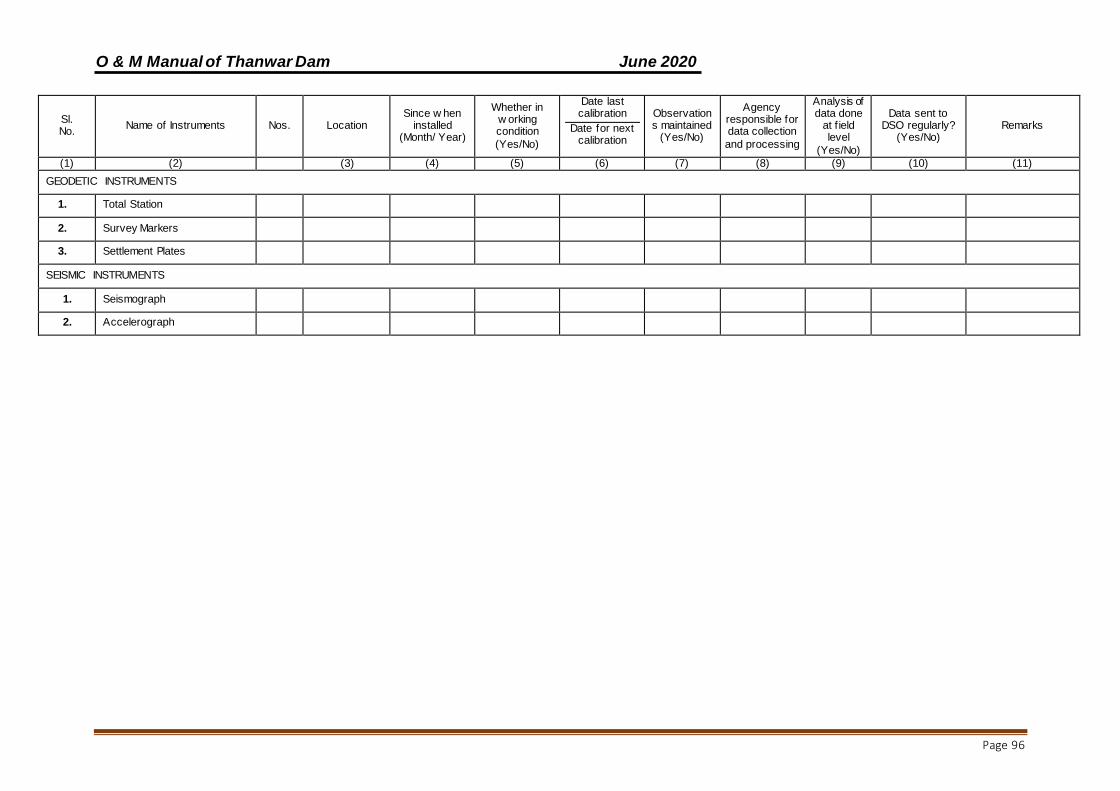
O & M Manual of Thanwar Dam June 2020
Page 96
Sl. No.
Name of Instruments Nos. Location Since w hen
installed (Month/ Year)
Whether in w orking condition
(Yes/No)
Date last calibration
Date for next calibration
Observations maintained
(Yes/No)
Agency responsible for data collection
and processing
Analysis of data done
at f ield level
(Yes/No)
Data sent to DSO regularly?
(Yes/No) Remarks
(1) (2) (3) (4) (5) (6) (7) (8) (9) (10) (11)
GEODETIC INSTRUMENTS
1. Total Station
2. Survey Markers
3. Settlement Plates
SEISMIC INSTRUMENTS
1. Seismograph
2. Accelerograph

O & M Manual of Thanwar Dam June 2020
Page 97
Appendix-III: Summary Table for Annual O&M Budget:
NO. BUDGET ITEM PREVIOUS
YEAR COST (Rs)
CURRENT YEAR BUDGET (YR ……..)
(Rs)
REMARKS
A. ESTABLISHMENT
1 SALARY OF REGULAR STAFF INCLUDING ALL OTHER BENEFITS
2 TRAVEL EXPENSES
3 OFFICE EXPENSES
4 MOTOR VEHICLE EXPENSES
5 MAINTENANCE OF OFFICE & COLONY COMPLEX
SUB-TOTAL - A
B. WORKS
1 CIVIL WORKS
1.1 CONCRETE / MASONRY DAM
1.2 EARTHEN DAM
1.3 INTAKE &OUTLETS IN EARTHEN DAMS/ ABUTMENTS
1.4 SLUICES IN CONCRETE / MASONRY DAMS
1.5 APPROACH / INSPECTION ROADS WITHIN DAM AREA
2 SLUICE GATES
2.1 OUTLETS IN EARTHEN DAMS - SERVICE / EMERGENCY GATES,
2.2 SLUICES IN CONCRETE / MASONRY DAMS – SERVICE / EMERGENCY GATES,
3 INSTRUMENTATION
4 MISCELLANEOUS WORKS
5 SALARY OF WORK- CHARGED STAFF INCLUDING ALL BENEFITS
6 MATERIALS TO BE STORED BEFORE MONSOON
SUB-TOTAL - B
7 CONTINGENCY (10%) ON
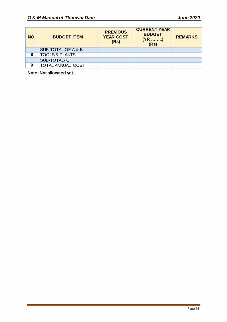
O & M Manual of Thanwar Dam June 2020
Page 98
NO. BUDGET ITEM PREVIOUS
YEAR COST (Rs)
CURRENT YEAR BUDGET (YR ……..)
(Rs)
REMARKS
SUB-TOTAL OF A & B 8 TOOLS & PLANTS
SUB-TOTAL- C
9 TOTAL ANNUAL COST
Note: Not allocated yet.
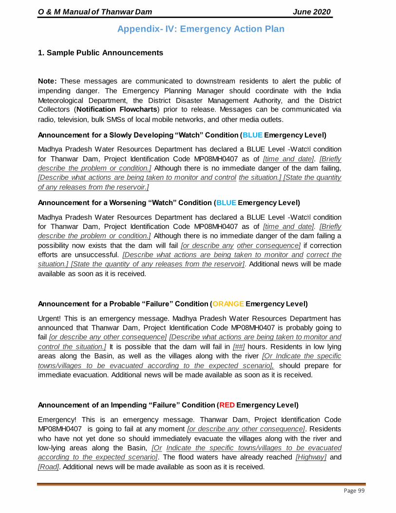
O & M Manual of Thanwar Dam June 2020
Page 99
Appendix- IV: Emergency Action Plan
1. Sample Public Announcements
Note: These messages are communicated to downstream residents to alert the public of
impending danger. The Emergency Planning Manager should coordinate with the India
Meteorological Department, the District Disaster Management Authority, and the District
Collectors (Notification Flowcharts) prior to release. Messages can be communicated via
radio, television, bulk SMSs of local mobile networks, and other media outlets.
Announcement for a Slowly Developing “Watch” Condition (BLUE Emergency Level)
Madhya Pradesh Water Resources Department has declared a BLUE Level ―Watch‖ condition
for Thanwar Dam, Project Identification Code MP08MH0407 as of [time and date]. [Briefly
describe the problem or condition.] Although there is no immediate danger of the dam failing,
[Describe what actions are being taken to monitor and control the situation.] [State the quantity
of any releases from the reservoir.]
Announcement for a Worsening “Watch” Condition (BLUE Emergency Level)
Madhya Pradesh Water Resources Department has declared a BLUE Level ―Watch‖ condition
for Thanwar Dam, Project Identification Code MP08MH0407 as of [time and date]. [Briefly
describe the problem or condition.] Although there is no immediate danger of the dam failing a
possibility now exists that the dam will fail [or describe any other consequence] if correction
efforts are unsuccessful. [Describe what actions are being taken to monitor and correct the
situation.] [State the quantity of any releases from the reservoir]. Additional news will be made
available as soon as it is received.
Announcement for a Probable “Failure” Condition (ORANGE Emergency Level)
Urgent! This is an emergency message. Madhya Pradesh Water Resources Department has
announced that Thanwar Dam, Project Identification Code MP08MH0407 is probably going to
fail [or describe any other consequence] [Describe what actions are being taken to monitor and
control the situation.] It is possible that the dam will fail in [##] hours. Residents in low lying
areas along the Basin, as well as the villages along with the river [Or Indicate the specific
towns/villages to be evacuated according to the expected scenario], should prepare for
immediate evacuation. Additional news will be made available as soon as it is received.
Announcement of an Impending “Failure” Condition (RED Emergency Level)
Emergency! This is an emergency message. Thanwar Dam, Project Identification Code
MP08MH0407 is going to fail at any moment [or describe any other consequence]. Residents
who have not yet done so should immediately evacuate the villages along with the river and
low-lying areas along the Basin, [Or Indicate the specific towns/villages to be evacuated
according to the expected scenario]. The flood waters have already reached [Highway] and
[Road]. Additional news will be made available as soon as it is received.

O & M Manual of Thanwar Dam June 2020
Page 100
Announcement of an Ongoing “Failure” Condition (RED Emergency Level)
Emergency! This is an emergency message. Thanwar Dam, Project Identification Code
MP08MH0407 failed [or describe any other consequence] at [time and date]. Residents who
have not yet done so should immediately evacuate the villages along with the river and low-lying
areas along the Basin, [Or Indicate the specific towns/villages to be evacuated according to the
expected scenario]. The flood waters have already reached [Highway] and [Road]. Additional
news will be made available as soon as it is received.
2. Dam Owner’s Responsibilities
The dam owner, Madhya Pradesh Water Resources Department, is responsible for all dam
operation and maintenance. The EAP is not intended to designate a specific person for a
specific responsibility but instead will designate the person’s duties or job description for both, before and during Emergency event Table 9
Officer Designation Responsibilities (During Preparedness and Emergency Events)
Executive Engineer
(Emergency Planning
Manager)
Preparedness Responsibilities:
- Coordinate routine inspections and Dam‘s operations. - Ensure effective transmission of hydro-metrological and stream flow data
through different means. - Ensure proper accessibility to all vulnerable points for constant monitoring
during emergency situations. - Identify primary secondary and communication systems, both internal
(between persons at the dam) and external (between dam personnel and outside entities).
- Provide security measures at the dam (CCTV surveillance, security
guards, fencing). - Ensure the availability of adequate staff at dam site during holidays,
nights and round the clock in weekdays. - Ensure that the EAP is functional and staffs are familiar with their
responsibilities.
- Ensure that a signboard is installed and clearly visual in different locations at dam site and operation room, with the most common
evidence of distress and corresponding levels of alert and remedial actions.
- Ensure all the equipment/means at dam site to response to an emergency
are easily accessible and well maintained (generators, vehicles, lanterns, radios, heavy equipment, etc)
- Ensure the installation and proper maintenance of a warning system (sirens, horns) in the critical areas within the floodplain (less than 2 hours
of wave arrival time) - Ensure the current approved version of the EAP is available to all
relevant stakeholders (those who have a functional role in the emergency
response) - Ensure all necessary means to manage the emergency response are
available and operative in the Emergency Operation Center.
- Participate in exercises for test/improvement of this EAP.
- In charge of organizing publicity at strategic points in Thanwar Dam.

O & M Manual of Thanwar Dam June 2020
Page 101
During Emergency Responsibilities:
- Ensure a continuous and reliable communication with dam site officers
- Receive and assess any distress condition as notified by site engineers, observer or regular inspection.
- Classify the incident/distress condition reported by the observer into the different Emergency Levels (Blue, Orange, Red) based on the
ANNEXURE 4 - (Emergency Level Determination/Action Sheets) and ANNEXURE 2
(Inundation Maps)
- Initiate/implement the Emergency Action Plan and the Emergency Operation Centre if it is deemed necessary.
- Identify the areas that would be potentially impacted by the emergency events.
- Provide updates of the situation to the District(s) Disaster Management Authority to assist them in making timely and accurate decisions
regarding warnings and evacuations. - Propagate the emergency information to other relevant stakeholders. - Support the communication needs of local emergency authority.
- Dam Site
Engineers
(Sub Divisional
Officer/Assistant
Engineers, Sub
Engineers)
Preparedness Responsibilities: - Monitor & surveillance of dam and appurtenant structures looking for
evidence of distress as mentioned in ANNEXURE 4 - Conduct Pre and Post monsoon Inspections under the direction of the
Emergency Planning Manager - Inform the Emergency Planning Manager about any irregular/unusual
condition at dam site and keep him/her posted about any progression/change
- Operate dam‘s gates/under sluices, under the express direction of Chief
Engineer/Superintending Engineer/Executive Engineer - Conduct routine dam maintenance
- Collect instrumentation measurements - Ensure effective working conditions of the warning system (Sirens)
- Participate in exercises for test/improvement of this EAP. -
During Emergency Responsibilities: - Monitor the emergency event at dam site and keep posted the
Emergency Planning Manager about any change in the development
- Contact the suppliers/contractors - Supervise the work of the labour contractors and machineries engaged in
the site for rehabilitation/remedial works
- Conduct the remedial actions as per Action Data Sheets (ANNEXURE 4)
Superintending
Engineer
Preparedness Responsibilities:
- Ensure an annual review of the EAP.
- Coordinate the annual / regular testing events of the EAP, such as tabletop exercises, mock drills, stakeholder‘s Consultation.
- Coordinate training events in problem detection, evaluation and appropriate corrective measures
- Supervise the functioning of control room and ensure to be well equipped with all type of information to facilitate the rescue and relief operations
- Ensure proper access to site at the earliest possible. - Ensure that all related machinery/equipment are in running conditions

O & M Manual of Thanwar Dam June 2020
Page 102
and can be deployed as per requirement at emergency site. - Formation of Purchase Committee / Committee in Consultation with C.E.,
Seoni for Procurement of Material from Appropriate Source through Spot Purchase.
- Ensure the correctness of Gauge Discharge sites under his control every year well before monsoon.
During Emergency Responsibilities:
- Provide decision support and technical support to Emergency Planning Manager as appropriate.
- Have a constant liaison with Indian Meteorological Department (IMD) during emergency periods related with flood events.
- Advise the Emergency Planning Manager of the emergency level
determination, if time permits. Disseminate information and make contact to utilize media as
appropriate at the time of emergency on behalf of Chief Engineer Seoni
Chief Engineer
Preparedness Responsibilities:
- Assist the Dam Owner‘s officers in preparation of Action Data Sheets
(ANNEXURE 4) - Recommend specific actions in order to improve the readiness of
emergency actions
- Support and Monitor the remedial construction activities such as earth moving, special investigations, etc.
- Decide depending upon the quantum of repair/reconstruction work, whether the work is to be got executed through large construction firms
or purely through the department or small contractors. - Undertake an engineering assessment of the safety hazard at the dam in
collaboration with the State Dam Safety Organization
During Emergency Responsibilities:
- Advice the dam‘s Emergency Planning Manager/Superintending Engineer
with the emergency level determination, if time permits. - Advice the dam‘s Emergency Planning Manager/Superintending Engineer
with remedial actions to take if Blue/Orange events occurs, and if time
permits. - Direct specific and appropriate procedures to open/close the spillway‘s
gates during the reservoir operation.
- Play the role of ―Public Affair‘s Officer in case external/public
notifications should be released. - Keep close watch on the different activities being carried out by
different agencies at the time of emergency
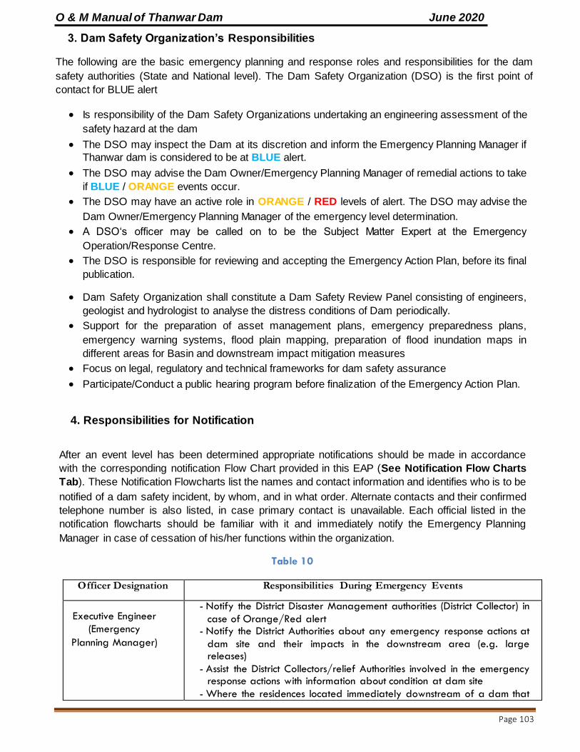
O & M Manual of Thanwar Dam June 2020
Page 103
3. Dam Safety Organization’s Responsibilities
The following are the basic emergency planning and response roles and responsibilities for the dam
safety authorities (State and National level). The Dam Safety Organization (DSO) is the first point of
contact for BLUE alert
Is responsibility of the Dam Safety Organizations undertaking an engineering assessment of the
safety hazard at the dam
The DSO may inspect the Dam at its discretion and inform the Emergency Planning Manager if
Thanwar dam is considered to be at BLUE alert.
The DSO may advise the Dam Owner/Emergency Planning Manager of remedial actions to take
if BLUE / ORANGE events occur.
The DSO may have an active role in ORANGE / RED levels of alert. The DSO may advise the
Dam Owner/Emergency Planning Manager of the emergency level determination.
A DSO‘s officer may be called on to be the Subject Matter Expert at the Emergency
Operation/Response Centre.
The DSO is responsible for reviewing and accepting the Emergency Action Plan, before its final
publication.
Dam Safety Organization shall constitute a Dam Safety Review Panel consisting of engineers,
geologist and hydrologist to analyse the distress conditions of Dam periodically.
Support for the preparation of asset management plans, emergency preparedness plans,
emergency warning systems, flood plain mapping, preparation of flood inundation maps in
different areas for Basin and downstream impact mitigation measures
Focus on legal, regulatory and technical frameworks for dam safety assurance
Participate/Conduct a public hearing program before finalization of the Emergency Action Plan.
4. Responsibilities for Notification
After an event level has been determined appropriate notifications should be made in accordance
with the corresponding notification Flow Chart provided in this EAP (See Notification Flow Charts
Tab). These Notification Flowcharts list the names and contact information and identifies who is to be
notified of a dam safety incident, by whom, and in what order. Alternate contacts and their confirmed
telephone number is also listed, in case primary contact is unavailable. Each official listed in the
notification flowcharts should be familiar with it and immediately notify the Emergency Planning
Manager in case of cessation of his/her functions within the organization.
Table 10
Officer Designation Responsibilities During Emergency Events
Executive Engineer
(Emergency
Planning Manager)
- Notify the District Disaster Management authorities (District Collector) in
case of Orange/Red alert - Notify the District Authorities about any emergency response actions at
dam site and their impacts in the downstream area (e.g. large releases)
- Assist the District Collectors/relief Authorities involved in the emergency response actions with information about condition at dam site
- Where the residences located immediately downstream of a dam that

O & M Manual of Thanwar Dam June 2020
Page 104
would be inundated within minutes of a dam failure, wherein the available warning time is very limited, in that cases, Emergency
Planning Manager will arrange to notify the residences directly without waiting for the local administration to act upon before an emergency
situation develops.
Dam Site Engineers
(Sub Divisional
Officer/ Assistant
Engineers)
- Keep inform the Emergency Planning Manager about the progress of
the situation at dam site.
Superintending Engineer/ Chief
Engineer
- Notify dam safety Organization and request technical advice as per required
- Notify/inform higher authorities on the mishap as per notification flow
chart of particular alert level as per situation at site.
- Notify/inform media representatives about the emergency situation. - Define emergency situations for which each medium will be utilized and
include an example of a news release that would be the most effective for each possible emergency, avoiding disseminate false/overstated messages among the population
District
Collector(s)/
District
Disaster
Management
Authority
- Implement the Notification Flow chart for regional and State Disaster Management Contacts
- Contact Local Law Enforcement Authorities and Relief Authorities under their jurisdiction
- Liaising and coordinating with Early Warning Agencies like IMD, CWC, INCOIS, etc. for disaster specific information and disseminating the information for coordinating with the State Govt. and facilitating the
deployment of NDRF in the disaster affected districts during disaster - Issue public announcements in coordination with Dam Owner‘s officials
and media representatives about the status of the emergency event
Relief Authorities (Police
Department, Civil
Defence, Army Forces)
- Notify downstream residents in vulnerable areas - Provide to the District Disaster Management Authority precise and
accurate feedback information about the progress of relief actions and advise when the emergency can be terminated
- Notify to their corresponding command the necessity to deploy more resources to attend the rescue and relief actions.
Media Representatives
- Disseminate wide public awareness during emergency condition of Dam through Social Media Platform such as Facebook, Twitter,
Whatsapp & Instagram. - The news media, including radio, television and newspapers, should
be utilized to the extent available and appropriate. - Pre-plan in coordination with Chief Engineer/Superintending Engineer
the most effective way to disseminate the most delicate and common
emergency situations among the population. Pre-defined news shall be available in order to improve readiness of the decision-making
process

O & M Manual of Thanwar Dam June 2020
Page 105
5. Responsibilities for Evacuation
Evacuation and relief actions are exclusive responsibilities of Districts Authorities, and emergency relief
forces at local and state level. For Thanwar Dam, only one District of Madhya Pradesh would be
directly affected by a potential failure/emergency event at the dam site, and therefore, each district‘s
representative is responsible for evacuation/relief actions in their jurisdiction.
District Collector(s) acting as District’s Disaster Management Authority is responsible to coordinate
actions along with the following specialized teams/forces: Police and Fire Departments, National
Disaster Management Authority (Response Force), Civil defence, Army Forces.
Within their responsibilities are:
UNDER NO EMERGENCY (Preparedness)
Participate in review, updates and exercises of the EAP
Dissemination among the population making them aware about their own risks.
Conduct training/education programs among the population in regard how to act before, during
and after emergency events such as flash floods.
UNDER ORANGE ALERT
Prepare emergency response personnel for possible evacuations that may be needed if a RED alert
is declared.
Provide resources as necessary to the dam owners.
Serve as the primary contact responsible for coordination of all emergency actions for potentially
affected communities.
Consider drafting a State of Local Emergency in preparation for RED alert.
Maintain close liaison with the district and the State Governments as well as the nearest units of
Armed Forces/Central police organizations and other relevant Central Government organizations
like Ministries of Communications, Water Resources, Health, Drinking Water, Surface Transport, who
could supplement the efforts of the district administration in the rescue and relief operations.
Decide in coordination with the Emergency Planning Manager when to terminate the Emergency.
UNDER RED ALERT
Initiate warnings and order evacuation of people under vulnerable areas as per inundation maps
(ANNEXURE 2 in EAP )
Direct local emergency response services (may include local law enforcement) to carry out the
evacuation of people and close roads/crossings within the evacuation area (see local Evacuation
Plan, ANNEXURE 3 and ANNEXURE 3 tables in EAP).
Declare a State of Local Emergency if required.
Provide resources as necessary to the dam owners.
Decide in coordination with the Emergency Planning Manager when to terminate the Emergency
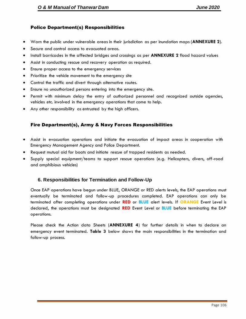
O & M Manual of Thanwar Dam June 2020
Page 106
Police Department(s) Responsibilities
Warn the public under vulnerable areas in their jurisdiction as per inundation maps (ANNEXURE 2).
Secure and control access to evacuated areas.
Install barricades in the affected bridges and crossings as per ANNEXURE 2 flood hazard values
Assist in conducting rescue and recovery operation as required.
Ensure proper access to the emergency services
Prioritize the vehicle movement to the emergency site
Control the traffic and divert through alternative routes.
Ensure no unauthorized persons entering into the emergency site.
Permit with minimum delay the entry of authorized personnel and recognized outside agencies,
vehicles etc. involved in the emergency operations that come to help.
Any other responsibility as entrusted by the high officers.
Fire Department(s), Army & Navy Forces Responsibilities
Assist in evacuation operations and initiate the evacuation of impact areas in cooperation with
Emergency Management Agency and Police Department.
Request mutual aid for boats and initiate rescue of trapped residents as needed.
Supply special equipment/teams to support rescue operations (e.g. Helicopters, divers, off-road
and amphibious vehicles)
6. Responsibilities for Termination and Follow-Up
Once EAP operations have begun under BLUE, ORANGE or RED alerts levels, the EAP operations must
eventually be terminated and follow-up procedures completed. EAP operations can only be
terminated after completing operations under RED or BLUE alert levels. If ORANGE Event Level is
declared, the operations must be designated RED Event Level or BLUE before terminating the EAP
operations.
Please check the Action data Sheets (ANNEXURE 4) for further details in when to declare an
emergency event terminated. Table 3 below shows the main responsibilities in the termination and
follow-up process.

O & M Manual of Thanwar Dam June 2020
Page 107
Table 11 - Termination and Follow-Up Responsibilities
Officer Designation Responsibilities (Termination and Follow-up)
Executive
Engineer
(Emergency
Planning
Manager)
- Declare the termination of the emergency operations in
coordination with District Disaster Management Authority and
Relief/Response Forces.
- Conduct a review process of the EAP procedures. - Identify EAP procedures that were followed effectively, as well
as any ways that the EAP could be improved. - Identify the causes that could have triggered the emergency
event and propose actions to improve readiness and early detection. Support from the Dam Safety Organization may be requested in this regard
- For Major Emergencies, the Emergency Planning manager will maintain detailed records of cost expended and will prepare a
detailed report in this regard. (See Section 7.3 “Reports”)
Superintending
Engineer/ Chief
Engineer
- Ensure that all parties that participated in the EAP activities are
involved in the review process. - Impose a time frame within which the EAP review is to be
completed.
- Propose any ways that the EAP could be improved. - Present the final results of the EAP evaluation in a documented
report to the Principal Secretary of Madhya Pradesh Water Resources Department.
- Ensure that there is no danger of spread of any epidemics or water borne diseases after the floods.
Dam Safety
Organization
(State /
Central level)
- Identify in coordination with the Emergency Planning Manager the causes that could have triggered the emergency event and propose actions to improve readiness and early detection. A
report should be presented to the dam owner‘s authorities in this regard.
District(s) - All
districts - and
National
Disaster
Management
Authority
- Declare the termination of the emergency operations in
coordination with Emergency Planning Manager and Relief/Response Forces.
- Identify EAP procedures that were followed effectively, as well
as any ways that the EAP could be improve

O & M Manual of Thanwar Dam June 2020
Page 108
WATCH CONDITION
NOTIFICATION FLOW CHART
(INTERNAL ALERT)
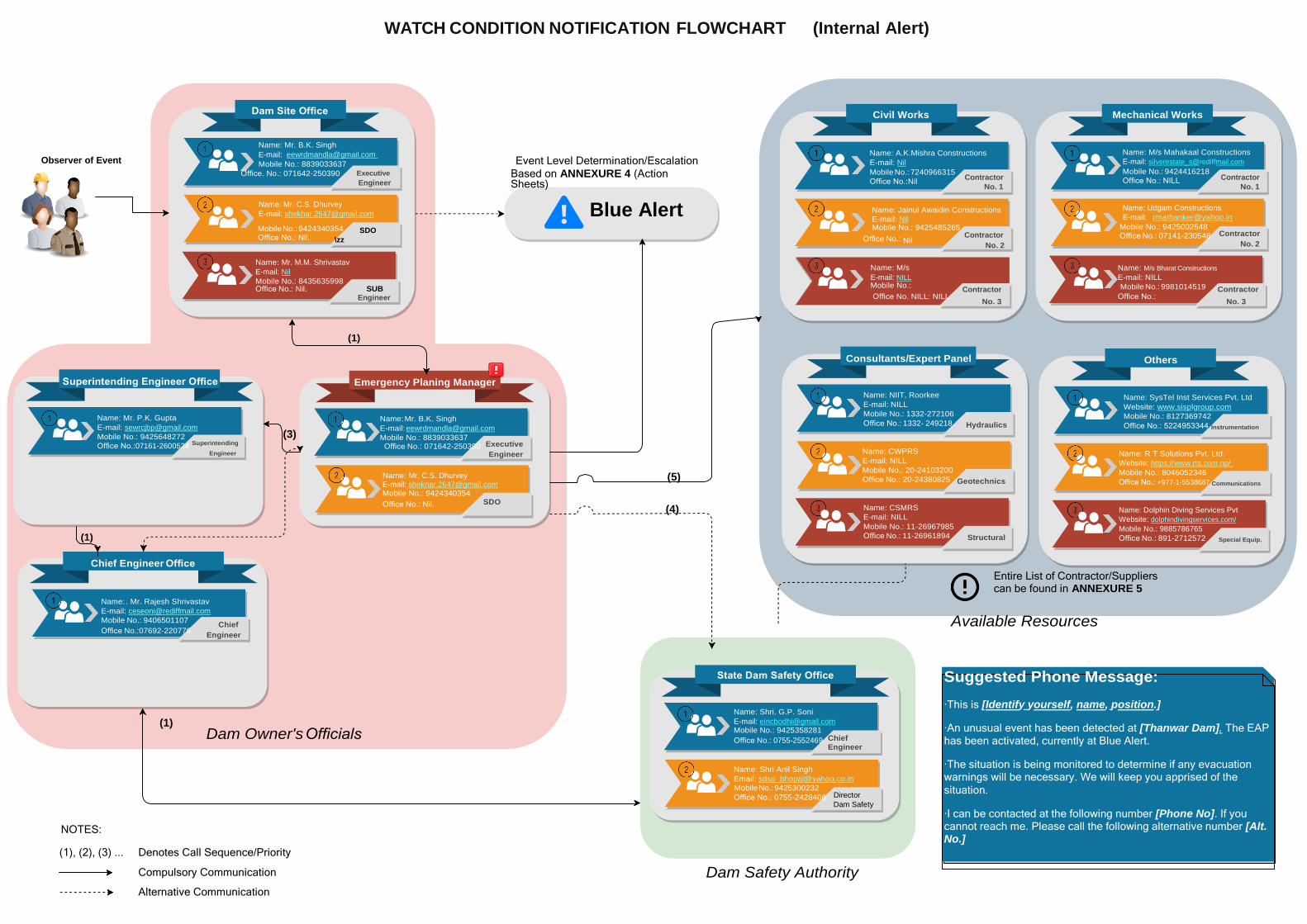
WATCH CONDITION NOTIFICATION FLOWCHART (Internal Alert)
Dam Site Office Civil Works Mechanical Works
Observer of Event
Name: Mr. B.K. Singh
E-mail: [email protected]
Mobile No.: 8839033637
Event Level Determination/Escalation
Name: A.K.Mishra Constructions
E-mail: Nil
Name: M/s Mahakaal Constructions
E-mail: [email protected]
Office. No.: 071642-250390 Executive Engineer
Based on ANNEXURE 4 (Action Sheets)
Mobile No.: 7240966315
Office No.:Nil Contractor
No. 1
Mobile No.: 9424416218
Office No.: NILL Contractor
No. 1
Name: Mr. C.S. Dhurvey
E-mail: [email protected] Blue Alert
Name: Jainul Awaidin Constructions
E-mail: Nil
Name: Udgam Constructions
E-mail: [email protected]
Mobile No.: 9424340354 Office No.: Nil.
SDO
\zz
Mobile No.: 9425485265
Office No.: Nil Contractor
No. 2
Mobile No.: 9425002548 Office No.: 07141-230548 Contractor
No. 2
Name: Mr. M.M. Shrivastav
E-mail: Nil
Mobile No.: 8435635998 Office No.: Nil. SUB
Name: M/s
E-mail: NILL Mobile No.:
Contractor
Name: M/s Bharat Constructions
E-mail: NILL
Mobile No.: 9981014519
Contractor
Engineer Office No. NILL: NILL No. 3
Office No.: No. 3
Superintending Engineer Office
Name: Mr. P.K. Gupta
E-mail: [email protected]
Mobile No.: 9425648272
Office No.:07161-2600534 Superintending
Engineer
(1)
(3)
(1)
Emergency Planing Manager
Name: Mr. B.K. Singh
E-mail: [email protected]
Mobile No.: 8839033637 Office No.: 071642-250390 Executive
Engineer
Name: Mr. C.S. Dhurvey E-mail: [email protected] Mobile No.: 9424340354
Office No.: Nil. SDO
(5)
(4)
Consultants/Expert Panel
Name: NIIT, Roorkee
E-mail: NILL
Mobile No.: 1332-272106
Office No.: 1332- 249218 Hydraulics
Name: CWPRS
E-mail: NILL
Mobile No.: 20-24103200
Office No.: 20-24380825 Geotechnics
Name: CSMRS
E-mail: NILL
Mobile No.: 11-26967985
Office No.: 11-26961894 Structural
Others
Name: SysTel Inst Services Pvt. Ltd
Website: www.sisplgroup.com
Mobile No.: 8127369742
Office No.: 5224953344 Instrumentation
Name: R T Solutions Pvt. Ltd.
Website: https://www.rts.com.np/
Mobile No.: 8046052346
Office No.: +977-1-5538687 Communications
Name: Dolphin Diving Services Pvt
Website: dolphindivingservices.com/
Mobile No.: 9885786765
Office No.: 891-2712572 Special Equip.
Chief Engineer Office
Name: . Mr. Rajesh Shrivastav
E-mail: [email protected]
Mobile No.: 9406501107 Chief
Office No.:07692-220776 Engineer
Entire List of Contractor/Suppliers can be found in ANNEXURE 5
Available Resources
(1)
Dam Owner's Officials
State Dam Safety Office
Name: Shri. G.P. Soni
E-mail: [email protected]
Mobile No.: 9425358281
Office No.: 0755-2552469 Chief Engineer
Name: Shri Anil Singh
Email: [email protected]
Suggested Phone Message:
·This is [Identify yourself, name, position.]
·An unusual event has been detected at [Thanwar Dam]. The EAP has been activated, currently at Blue Alert.
·The situation is being monitored to determine if any evacuation warnings will be necessary. We will keep you apprised of the
NOTES:
(1), (2), (3) ...
Denotes Call Sequence/Priority
Mobile No.: 9425300232
Office No.: 0755-2428406 Director
Dam Safety
situation.
·I can be contacted at the following number [Phone No]. If you cannot reach me. Please call the following alternative number [Alt. No.]
Compulsory Communication
Alternative Communication
Dam Safety Authority

O & M Manual of Thanwar Dam June 2020
Page 109
FAILURE CONDITION
NOTIFICATION FLOW CHART
(EXTERNAL ALERT)
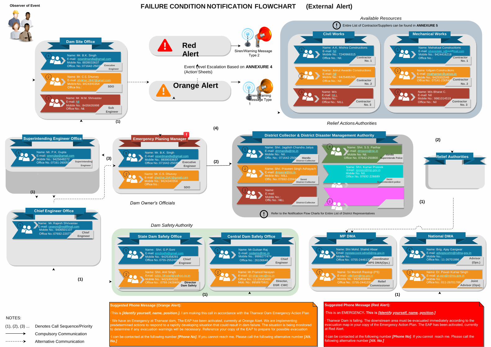
Observer of Event FAILURE CONDITION NOTIFICATION FLOWCHART (External Alert)
Available Resources
Entire List of Contractor/Suppliers can be found in ANNEXURE 5
Dam Site Office
Name: Mr. B.K. Singh
E-mail: [email protected]
Mobile No. 8839033637
Red Alert
Siren/Warning Message
Type 2
Civil Works
Name: A.K. Mishra Constructions
E-mail: Nil Mobile No.: 7240966315
Office No.: Nil. Contractor No. 1
Mechanical Works
Name: Mahakaal Constructions
E-mail: [email protected]
Mobile No.: 9424416218
Office No.: Contractor No. 1
Office. No.:071642-250390 Executive
Engineer
Name: Mr. C.S. Dhurvey
E-mail: [email protected]
Event Level Escalation Based on ANNEXURE 4
(Action Sheets)
Name: Jainul Awaidin Constructions
E-mail: Nil Mobile No.: 9425485265
Office No.: Nil Contractor
Name: Udgam Constructions
E-mail: [email protected]
Mobile No.: 9425002548 Office No.: 07141-230548 Contractor
Mobile No.: 9424340354
Office No.:
SDO Orange Alert
Name: M/s
No. 2
Name: M/s Bharat C.
No. 2
Name: Mr. M.M. Shrivastav
E-mail: Nil
Mobile No.: 8435635998 Office No.: Nil. Sub
Engineer
Siren/Warning
Message Type
1
E-mail: NILL
Mobile No.:
Office No.: NILL Contractor No. 3
E-mail: Nil Mobile No.: 9981014519
Office No.: Nil Contractor No. 3
Superintending Engineer Office
(1)
Emergency Planing Manager
(4)
Relief Actions Authorities
District Collector & District Disaster Management Authority
(2)
(1)
Name: Mr. P.K. Gupta
E-mail: [email protected]
Mobile No.: 9425648272 Office No.:07161-2600534 Superintending
Engineer
:
(3)
Name: Mr. B.K. Singh
E-mail: [email protected]
Mobile No.: 8839033637 Office No.:071642-250390 Executive
Engineer
Name: Mr. C.S. Dhurvey
E-mail: [email protected]
Mobile No.: 9424340354 Office No.:
SDO
Dam Owner's Officials
(2)
Name: Shri. Jagdish Chandra Jatiya
E-mail: [email protected]
Mobile No.: Nil.
Offic. No.: 071642-250600 Mandla
District Collector
Name: Shri. Praveen Singh Adhayach
E-mail: [email protected] Mobile No.: NILL
Offic. No.:07692-220444 Seoni
District Collector
Name:
E-mail:
Mobile No.: Offic No.: NILL
District Collector
Name: Shri. S.S. Parihar
E-mail: [email protected]
Mobile No: Nil. Mandla Office No. 07642-250800 Superintende Police
Name: Shri. Kumar Prateek
Email: [email protected] Mobile No. Nil. Office No. 07692-226689
Seoni
Superintendent police
(1)
Relief Authorities
Chief Engineer Office
Refer to the Notification Flow Charts for Entire List of District Representatives
Name: Mr. Rajesh Shrivastav E-mail: [email protected]
Mobile No.: 9406501107
Office No.:07692-220776 Chief
Engineer
Dam Safety Authority
State Dam Safety Office
Central Dam Safety Office
MP DMA
National DMA
Name: Shri. G.P.Soni
E-mail: [email protected]
Mobile No.: 9425358281 Office No.:0755-2552469 Chief Engineer
Name: Mr.Gulsan Raj
E-mail: [email protected] Mobile No.: 9999277474
Office No.: 26106848 Chief
Engineer
Name: Shri Mohd. Shahid Absar
Email: [email protected]
Mobile No.: Office No.: 0755-2446132 Coordinator
MPS DMA(Ops.)
Name: Brig. Ajay Gangwar
E-mail: [email protected]
Mobile No.: Office No.: 11-26701886 Advisor
(Ops.)
(1)
Name: Shri. Anil Singh
Email: [email protected]
Mobile No.: 9425300232 Office No.: 0755-2428406 Director
Dam Safety
Name: Mr.Pramod Narayan
E-mail: [email protected]
Office No.: 11-29583480 Mob. No.: 9958975921 Director,
DSR CWC
Name: Sri Manish Rastogi (PS)
E-mail: [email protected] Mobile No.: 9425469444
Office No.: 0755-2441335 Relief Commissioner
Name: Dr. Pavan Kumar Singh
E-mail: [email protected]
Mobile No.: Office No.: 011-26701788 Joint
Advisor (Ops)
(1) (1)
NOTES:
(1), (2), (3) ...
Denotes Call Sequence/Priority
Compulsory Communication
Alternative Communication
Suggested Phone Message (Orange Alert):
·This is [Identify yourself, name, position.]. I am making this call in accordance with the Thanwar Dam Emergency Action Plan
· We have an Emergency at Thanwar dam. The EAP has been activated, currently at Orange Alert. We are implementing
predetermined actions to respond to a rapidly developing situation that could result in dam failure. The situation is being monitored
to determine if any evacuation warnings will be necessary. Reference your copy of the EAP to prepare for possible evacuation
·I can be contacted at the following number [Phone No]. If you cannot reach me. Please call the following alternative number [Alt.
No.]
Suggested Phone Message (Red Alert):
·This is an EMERGENCY. This is [Identify yourself, name, position.]
· Thanwar Dam is failing. The downstream area must be evacuated immediately according to the evacuation map in your copy of the Emergency Action Plan. The EAP has been activated, currently
at Red Alert.
·I can be contacted at the following number [Phone No]. If you cannot reach me. Please call the
following alternative number [Alt. No.]

O & M Manual of Thanwar Dam June 2020
Page 110
This page is left blank intentionally

O & M Manual of Thanwar Dam June 2020
Page 111
Appendix-IV: Basic Drawings of the Dam &Spillway.

O & M Manual of Thanwar Dam June 2020
Page 112
This page is left blank intentionally

O & M Manual of Thanwar Dam June 2020
Page 113
1. Index Map:
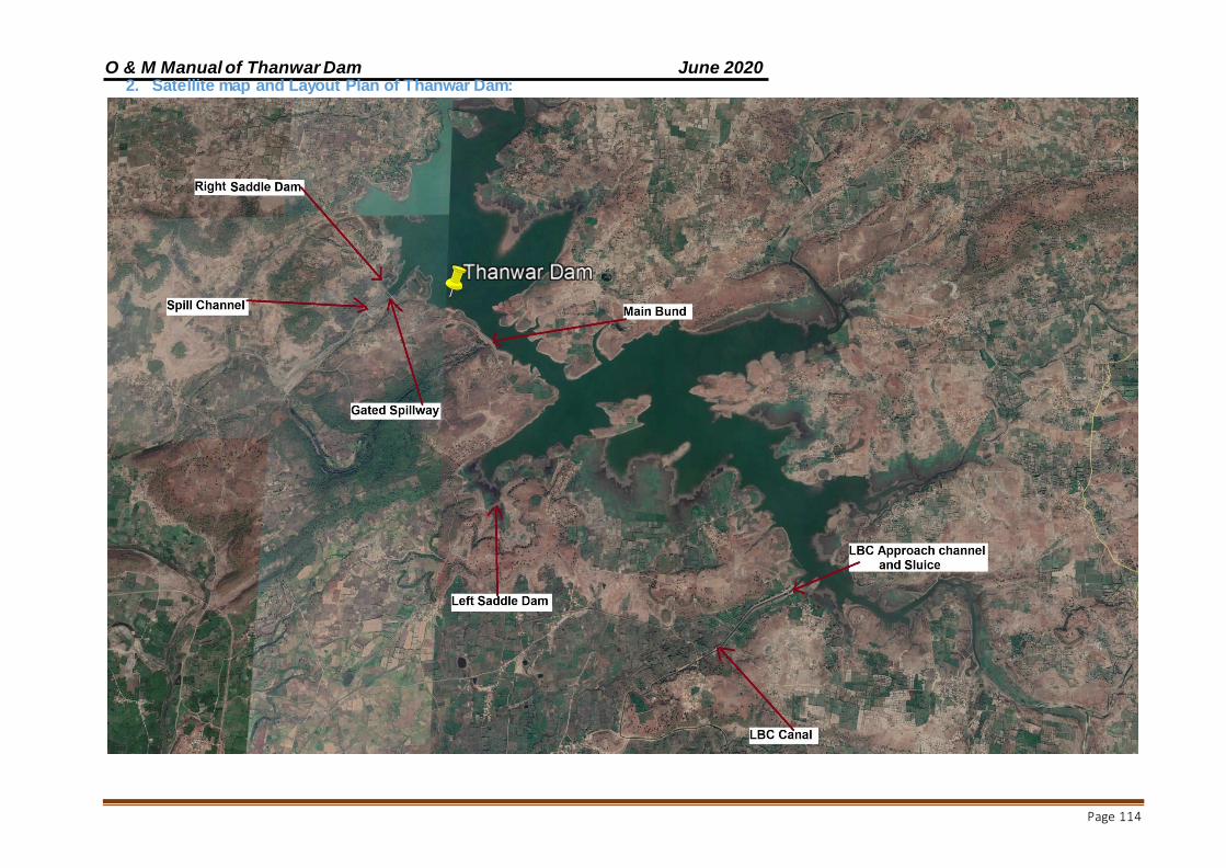
O & M Manual of Thanwar Dam June 2020
Page 114
2. Satellite map and Layout Plan of Thanwar Dam:

O & M Manual of Thanwar Dam June 2020
Page 115
3. Location Map:
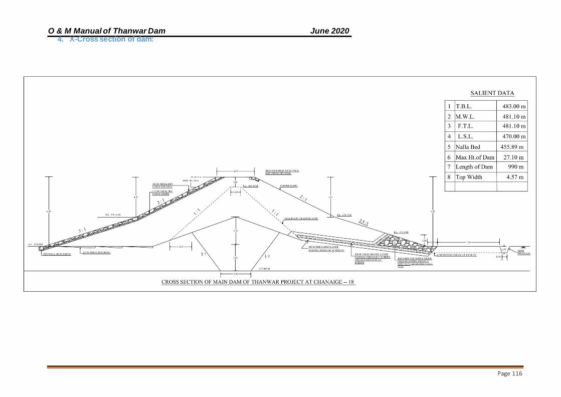
O & M Manual of Thanwar Dam June 2020
Page 116
4. X-Cross section of dam:

O & M Manual of Thanwar Dam June 2020
Page 117
5. X-Cross section of Spillway of dam:

O & M Manual of Thanwar Dam June 2020
Page 118
6. L-Section of Dam:
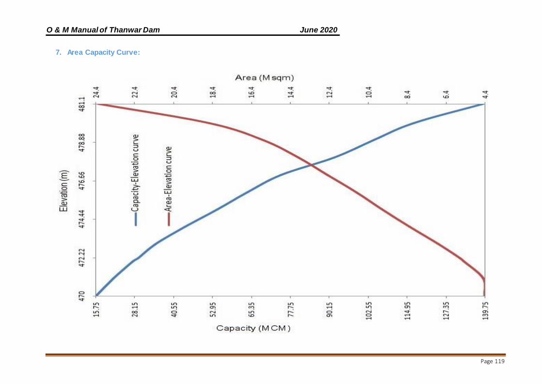
O & M Manual of Thanwar Dam June 2020
Page 119
7. Area Capacity Curve:
O & M Manual of Thanwar Dam June 2020
Page 120
Appendix-VI: References
Central Water Commission (2018): Guidelines for Preparing Operation and Maintenance Manual for Dams, Doc. No.
CDSO_GUD_DS_03_v1.0 published under DRIP
Central Water Commission (2018): Guidelines for Instrumentation of Large Dams, Doc. No. CDSO_GUD_DS_02_v1.0 Published under
DRIP
Central Water Commission (1987): Guidelines for Safety Inspection of Dams, Doc. No. CDSO_GUD_DS_07_v1.0 Published under DRIP
Central Water Commission (2016): Guidelines for Developing Emergency Action Plan (EAP) for Dams, Doc. No.
CDSO_GUD_DS_01_v1.0
IS: 15472 (2004): Guidelines for Planning & Design of Low Level Outlets for Evacuating Storage Reservoirs
IS: 7323 (1994): Indian Standards- Operation of Reservoir- Guidelines
IS: 10096, Part 3 (2002): Recommendations for Inspection, Testing and Maintenance of Radial Gates and Rope Drum Hoists- Part 3 After
Erection
IS: 14177, Part-II (1994): Guidelines for Painting System for Hydraulic Gates and Hoists
IS: 2339 (1963) : Specifications for Aluminium Paint for General Purposes in dual container
IS: 11223 (1985) : Guidelines for Fixing Spillway Capacity
IS: 2932-2003- Part 1: Enamel, Synthetic, Exterior (a) Under coating (b) Finishing-specifications: Part 1 For Domestic and decorative
applications
Government of Rajasthan, Department of Water Resources (October 2010): Guidelines to prepare Manual of Operation & Maintenance of
Irrigation Structures,
Madhya Pradesh Water Resources Department, Operation and Maintenance series technical circular no. 3, “August 2015, Periodical (Bi-
annual) Inspection of Dams (Head Works)”.
O & M Manual of Thanwar Dam June 2020
Page 121
Appendix-VII: Glossary

Abutment - that part of a valley side against which a dam is constructed. Right and left abutments are those on respective sides of the observer looking downstream.
Air Vent Pipe - a pipe designed to provide air
to the outlet conduit to reduce turbulence during release of water and safeguard against damages due to cavitation.
Appurtenant Structures - ancillary features
of a dam, such as the outlet, spillway, energy dissipation arrangement powerhouse, tunnels, etc.
Arch Dam - a concrete or masonry dam that is curved to transmit the major part of the water pressure to the abutments.
Auxiliary Spillway (Emergency Spillway) - a
secondary spillway designed to operate only during exceptionally large floods.
Base Width (Base Thickness) - the
maximum width or thickness of a dam measured horizontally between upstream and down- stream faces and normal (perpendicular) to the axis of the dam but excluding projections for outlets, etc.
Berm - a horizontal step or bench in the
sloping profile of an embankment dam.
Buttress dam - a dam consisting of a watertight upstream face supported at intervals on the downstream side by a series of but-tresses.
Cofferdam - a temporary structure enclosing
all or part of a construction area so that construction can proceed in a dry area.
Concrete Lift - in concrete works the vertical
distance between successive horizontal construction joints.
Conduit Outlet Works - a closed conduit for
conveying discharge through or under a dam for different project purposes. Consolidation Grouting (Blanket Grouting)-
the injection of grout to consolidate a layer of the foundation, resulting in greater im permeability, strength, or both.
Construction Joint - the interface between
two successive placing or pours of concrete where a bond, not permanent separation, is
intended.
Core Wall - a wall built of impervious material,
usually concrete or asphaltic concrete, in the body of an embankment dam to prevent leakage.
Crest gate (spillway gate) - a gate on the crest of a spillway to control overflow or reservoir water level.
Crest Length - the length of the dam at its crest
(dam top) top of a dam, including the length of the spillway, powerhouse, navigation lock, fish pass, etc., where these structures form part of the length of a dam. If detached from a dam, these structures should not be included.
Crest of dam - Used to indicate the “top of dam”. To avoid confusion to indicate the crest of spillway and top of dam may be used.
Culvert - a drain or waterway built under a road,
railway, or embankment, usually consisting of a pipe or covered conduits.
Cut off - an impervious construction or material
which reduces seepage through the foundation material.
Cut off trench - an excavation later to be filled with impervious material to form a cutoff.
Cut off wall - a wall of impervious material (e.g.,
concrete, asphaltic concrete, steel-sheet piling) built into the foundation to reduce seepage under the dam.
Dam - any artificial barrier including appurtenant
works constructed across rivers or tributaries thereof with a view to impound or divert water; includes barrage, weir and similar water impounding structures but does not include water conveyance structures such as canal, aqueduct and navigation channel and flow regulation structures such as flood embankments, dikes, and guide bunds. Dam failure - failures in the structures or operation
of a dam which may lead to the uncontrolled release of impounded water resulting in downstream flooding affecting the life and property of the people. Dam incident - all problems occurring to a dam that has not degraded into „dam failure‟ and including the following: a) Structural damage to the dam and appurtenant works;

b) Unusual readings of instruments in the dam; c) Unusual seepage or leakage through the dam body; d) Change in the seepage or leakage regime; e) Boiling or artesian conditions noticed below an earth dam; f) Stoppage or reduction in seepage or leakage from the foundation or body of the dam into any of the galleries, for dams with such galleries; g) Malfunctioning or inappropriate operation of gates;
h) Occurrence of any flood, the peak of which exceeds the available flood discharge capacity or 70% of the approved design flood; i) Occurrence of a flood, which resulted in encroachment on the available free-board, or the adopted design freeboard; j) Erosion in the near vicinity, up to five hundred meters, downstream of the spillway, waste weir, etc.; and k) Any other event that prudence suggests would have a significant unfavorable impact on dam safety. Dam inspection - on-site visual examination
of all components of dam and its appurtenances by one or more persons trained in this respect and includes investigation of the non- overflow portion, spillways, abutments, stilling basin, piers, bridge, down-stream toe, drainage galleries, operation of mechanical systems (including gates and its components, drive units, cranes), interior of outlet conduits, instrumentation records, and record-keeping arrangements. Dam owner - the Central Government or a State Government or public sector undertaking or local authority or company and any or all of such persons or organizations, who own, control, operate or maintain a specified dam.
Dam safety - the practice of ensuring the
integrity and viability of dams such that they do not present unacceptable risks to the public, property, and the environment. It requires the collective application of engineering principles and experience, and a philosophy of risk management that recognizes that a dam is a structure whose safe function is not explicitly determined by its original design and construction. It also includes all actions taken to identify or predict deficiencies and consequences related to failure, and to document, publicize, and reduce, eliminate, or remediate to the extent reasonably possible, any unacceptable risks.
Dead storage - the storage that lies below the invert of the lowest outlet and that, therefore, cannot be withdrawn from the reservoir.
Decommission - Taking a dam out of service in an environmentally sound and safe manner or converting it to another purpose.
Design flood - see spillway design flood.
Design life - the intended period that the dam will
function successfully with only routine maintenance; determined during design phase.
Distress condition - the occurrence or potential
development of such conditions in the dam or appurtenance or its reservoir or reservoir rim, which if left unattended to, may impede the safe operation of dam for its intended benefits or may pose unacceptable risks to the life and property of people downstream.
Diversion channel, canal, or tunnel - a waterway
used to divert water from its natural course. These terms are generally applied to temporary structures such as those de-signed to bypass water around a dam site during construction. “Channel‟ is normally used instead of “canal” when the waterway is short. Occasionally these terms are applied to permanent structures.
Documentation - all permanent records concerning investigation, design, construction, operation, performance, maintenance and safety of dams and includes design memorandum, construction drawings, geological reports, reports of specialized studies simulating structural and hydraulic response of the dam, changes made in design and drawings, quality control records, emergency action plan, operation and maintenance manual, instrumentation readings, inspection and testing reports, operational reports, and dam safety review reports.
Drainage area - an area that drains naturally to a
point on a river.
Drainage layer or blanket - a layer of permeable material in a dam to relieve pore pressure or to facilitate drainage of fill.
Drawdown - the lowering of water surface level due
to release of water from a reservoir.
Earth dam (Earth fill dam) - An embankment
dam in which more than 50 percent of the total volume is formed of compacted fine- grained material obtained from a borrow area.
Earthen dam or earth filled dam - see
embankment dam.
Embankment dam (Fill dam) - any dam constructed of excavated natural materials. Emergency Action Plan (EAP) - a plan of action to be taken to reduce the potential for damage to property and loss of life in the area affected by failure of a dam or other potentially hazardous practice.
Emergency gate - a standby or reserve gate which is lowers only for repairing / servicing of the service gate.
Emergency spillway - see spillway
Face - the external surface of a structure,
e.g., the surface of a wall of a dam.
Failure - the uncontrolled release of water
from a dam.
Filter (filter zone) - A band or zone of
granular material that is incorporated into a dam and is graded (either naturally or by selection) to allow seepage to flow across or down the filter without causing the migration of material from zones adjacent to it.
Fixed wheel gate (fixed-roller gate, fixed axle gate) - a gate having wheels or rollers
mounted on the end posts of the gate. The wheels move against rails fixed in side grooves or gate guides.
Flashboards - a length of timber, concrete, or
steel placed on the crest of a spillway to raise the retention water level but that may be quickly removed in the event of a flood, either by a tripping device or by deliberately designed failure of the flashboard or its supports.
Flood gate - a gate to control flood release
from a reservoir.
Flood routing - the determination of the
attenuating effect of storage on a flood passing through a valley, channel, or reservoir.
Flood surcharge - the volume or space in a
reservoir between the controlled retention water level (Full Reservoir Level) and the maximum water level. Flood surcharge cannot be retained in the reservoir but will flow over the spillway until the controlled retention water level is reached.
Flood wall - a concrete wall constructed adjacent
to a stream to prevent flooding of property on the landward side of the wall, normally constructed in lieu of or to supplement a levee where the land required for levee construction is expensive or not avail-able.
Flood plain - an area adjoining a body of water or natural stream that has been, or may be, covered by flood water.
Flood plain management - a management
program to reduce the consequences of flooding, either by natural runoff or by dam failure, to existing and future properties in a floodplain.
Foundation of dam - the natural material on which
the dam structure is placed.
Freeboard - the vertical distance between a stated
reservoir level and the top of a dam. Normal freeboard is the vertical distance between Full Reservoir Level (FRL) and the top of the dam. Minimum freeboard is the vertical distance between the Maximum Water Level (MWL) and the top of the dam.
Full Reservoir Level (FRL)/Normal water level
- for a reservoir with un-gated spillway it is the spillway crest level. For a reservoir, whose outflow is controlled wholly or partly by movable gates, siphons or other means, it is the maximum level to which water can be stored under normal operating conditions, exclusive of any provision for flood surcharge Gallery - (a) a passageway within the body of a dam or abutment, hence the terms grouting gallery, inspection gallery and drainage gallery (b) a long and rather narrow hall, hence the following terms for a power plant viz. valve gallery, transformer gallery and bus bar gallery. Gate - a device in which a leaf or member is moved across the waterway from an external position to control or stop the flow.
Gravity dam - a dam constructed of concrete,
masonry, or both that relies on its weight for stability. Grout cap - a pad or wall constructed to
facilitate pressure grouting of the grout curtain beneath it.
Grout curtain (grout cut off) - a barrier
produced by injecting grout into a vertical zone, usually narrow horizontally, in the foundation to reduce seepage under a dam.
Hazard Classification - a system that
categorizes dams according to the degree of adverse incremental consequences of a failure or improper operation of the dam. CWC classifies dam hazards as “low”, “significant”, or “high”.
. Height above lowest foundation - the
maximum height from the lowest point of the general foundation to the top of the dam.
Homogeneous earth fill dam - an
embankment dam constructed of similar earth material throughout, except internal drains or drainage blankets; distinguished from a zoned earth fill dam.
Hydraulic fill dam - an embankment dam
constructed of materials, often dredged, that are conveyed and placed by suspension in flowing water.
Hydraulic height - the height to which water
rises behind a dam and the difference between the lowest point in the original streambed at the axis of the dam and the maximum controllable water surface.
Hydrograph - a graphic representation of discharge, stage, or other hydraulic property with respect to time for a point on a stream. (At times the term is applied to the phenomenon the graphic representation describes; hence a flood hydrograph is the passage of a flood discharge past the observation point.)
Inclinometer - an instrument, usually
consisting of a metal or plastic tube inserted in a drill hole and a sensitized monitor either lowered into the tube or fixed within it. The monitor measures at different points the tube’s inclination to the vertical. By integration, the lateral position at various levels of the tube may be found relative to a point, usually the
top or bottom of the tube, assumed to be fixed. The system may be used to measure settlement. Intake - any structure in a reservoir, dam, or river through which water can be drawn into an aqueduct.
Internal Erosion - see piping.
Inundation map - a map delineating the area that
would be inundated in case of a failure.
Leakage - Uncontrolled loss of water by flow
through a hole or crack.
Lining - a coating of asphaltic concrete, reinforced
or unreinforced concrete, shotcrete, rubber or plastic on a canal, tunnel etc. to provide water tightness, prevent erosion, reduce friction, or support the periphery of structure. May also refer to lining, such as steel or concrete, of outlet pipe or conduit.
Low-level outlet (bottom outlet) - an opening at a
low level from a reservoir generally used for emptying or for scouring sediment and sometimes for irrigation releases.
Maintenance - the recurring activities necessary to
retain or restore a dam in a safe and functioning condition, including the management of vegetation, the repair or replacement of failed components, the prevention or treatment of deterioration, and the repair of damages caused by flooding or vandalism.
Masonry dam - a dam constructed mainly of stone,
brick or concrete blocks that may or may not be joined with mortar. A dam having only a masonry facing should not be referred to as a masonry dam.
Maximum cross-section of dam - a cross section of a dam at the point of its maxi-mum height. Maximum water level - the maximum water level, including flood surcharge, the dam is designed to withstand.
Membrane (Diaphragm) - a sheet or thin zone or
facing made of a flexible material, sometimes referred to as a diaphragm wall or diaphragm.
Minimum operating level - the lowest level to
which the reservoir is drawn down under normal operating conditions.
Morning glory spillway - see spillway. One-
Hundred Year (100-Year) Exceedance Interval
- the flood magnitude expected to be equaled or exceeded on the average of once in 100 years. It may also be expressed as an exceedance frequency, i.e. a percent chance of being exceeded in any given year. Operation - the administration, management, and performance of maintenance activities necessary to keep a dam safe and functioning as planned.
Outlet - an opening through which water can
be freely discharged from a reservoir.
Outlet gate - a gate controlling the outflow of
water from a reservoir.
Overflow dam - a dam designed to be
overtopped.
Parapet Wall - a solid wall built along the top
of a dam for ornament, for the safety of vehicles and pedestrians, or to prevent overtopping.
Peak Flow - the maximum instantaneous
discharge that occurs during a flood. It coincides with the peak of a flood hydrograph.
Pervious Zone - a part of the cross-section of
an embankment dam comprising material of high permeability.
Phreatic Surface - the top most flow line in an
embankment dam.
Piezometer - an instrument for measuring pore water pressure within soil, rock, or concrete.
Piping - the progressive development of
internal erosion by seepage, appearing downstream as a hole or seam discharging water that contains soil particles.
Pore Pressure - the interstitial pressure of
water within a mass of soil, rock, or concrete.
Pressure Cell - an instrument for measuring
pressure within a mass of soil, rock, or concrete or at an interface between one and the other.
Pressure Relief Pipes - Pipes used to relieve uplift or pore water pressure in a dam’s foundation or structure.
Primary Spillway (Principal Spillway) - the
principal or first-used spillway during flood flows.
Probable Maximum Flood (PMF) - a flood that would result from the most severe combination of critical meteorologic and hydrologic conditions possible in the region.
Probable Maximum Precipitation (PMP) - the
maximum amount and duration of precipitation that can be expected to occur on a drainage basin.
Program ― any authorized activity used to
implement and carry out goals, actions, and objectives contained within the authorizing legislation.
Program Life - the period in a contract,
conservation plan, or plan during which the conservation practice or conservation sys-tem shall be maintained and used for the intended purpose; determined by program requirements.
Pumped storage reservoir - a reservoir filled entirely or mainly with water pumped from outside its natural drainage area.
Radial gate - a gate with a curved upstream plate
and radial arms hinged to piers or other supporting structures.
Regulating dam - a dam impounding a reservoir
from which water is released to regulate
Rehabilitation - the completion of all work
necessary to extend the service life of the practice or component and meet applicable safety and performance standards.
Relief well - vertical wells or boreholes,
constructed downstream of an embankment dam to relieve the pressure from confined pervious layers in foundation overlaid by an impervious layer to arrest boiling.
Repair - actions to restore deteriorated, damaged,
or failed dam or its component to an acceptable by meeting functional condition.
Replacement - the removal of a structure or component and installation of a similar, functional structure or component.
Reservoir area - the surface area of a reservoir
when filled to controlled retention level.
Reservoir routing - the computation by which
the interrelated effects of the inflow hydrograph, reservoir storage, and discharge from the reservoir are evaluated.
Reservoir surface - the surface of a reservoir
at any level.
Riprap - a layer of large stones, broken rock,
or precast blocks placed randomly on the upstream slope of an embankment dam, on a reservoir shore, or on the sides of a channel as a protection against wave action. Large riprap is sometimes referred to as armouring.
Risk assessment - as applied to dam safety,
the process of identifying the likelihood and consequences of dam failure to provide the basis for informed decisions on a course of action.
Rock fill dam - an embankment dam in which
more than 50 percent of the total volume comprises compacted or dumped pervious natural or crushed rock.
Rock fill Dam - see embankment dam.
Roll Crete or Roller-Compacted Concrete -
A no-slump concrete that can be hauled in
dump trucks, spread with a bull-dozer or grader, and compacted with a vibratory roller.
Rolled fill dam―an embankment dam of earth or rock in which the material is placed in layers and compacted using rollers or rolling equipment.
Seepage - the interstitial movement of water
that may take place through a dam, its foundation, or its abutments. Service Life - the actual period after
construction of a dam, during which the practice functions adequately and safely with only routine maintenance; determined by onsite review.
Service/Regulating gate (regulating valve) - a gate or valve that operates under full pressure and flow to throttle and vary the rate of discharge. Shaft Spillway (Morning Glory Spill-way -
water spills and then is conducted through, under, or around a dam by means of a conduit or tunnel.
If the upper part of the shaft is splayed out and
terminates in a circular horizontal weir, it is termed a “bell mouth” or “morning glory” spillway.
Side Channel Spillway - a spillway whose crest is
roughly parallel to the channel immediately downstream of the spillway.
Sill - (a) A submerged structure across a river to
control the water level upstream. (b) The crest of a spillway. (c) A horizontal gate seating, made of wood, stone, concrete or metal at the invert of any opening or gap in a structure, hence the expressions gate sill and stop log sill.
Siphon Spillway - a spillway with one or more
siphons built at crest level. This type of spillway is sometimes used for providing automatic surface-level regulation within narrow limits or when considerable discharge capacity is necessary within a short period.
Slide gate (sluice gate) - a gate that can be
opened or closed by sliding it in supporting guides.
Slope - (a) the side of a hill or mountain. (b) The
inclined face of a cutting or canal or embankment. (c) Inclination from the horizontal. In the United States, it is measured as the ratio of the number of units of horizontal distance to the number of corresponding units of vertical distance. The term is used in English for any inclination and is expressed as a percentage when the slope is gentle, in which case the term gradient is also used.
Slope Protection - the protection of a slope
against wave action or erosion.
Sluiceway - see low-level outlet
Spillway - a structure over or through which flood
flows are discharged. If the flow is controlled by gates, it is a controlled spillway; if the elevation of the spillway crest is the only control, it is an uncontrolled spillway.
Spillway Channel (Spillway Tunnel) - a channel
or tunnel conveying water from the spillway to the river downstream.
Stilling Basin - a basin constructed to dissipate the
energy of fast-flowing water, e.g., from a spillway or bottom outlet, and to protect the riverbed from erosion.

.Stop logs - large logs or timber or steel
beams placed on top of each other with their ends held in guides on each side of a channel or conduit providing a cheaper or easily handled temporary closure than a bulkhead gate.
Storage - the retention of water or delay of
runoff either by planned operation, as in a reservoir, or by temporary filling of over-flow areas, as in the progression of a flood crest through a natural stream channel.
Tail water Level - the level of water in the
tailrace at the nearest free surface to the turbine or in the discharge channel immediately downstream of the dam. Tailrace - the tunnel, channel or conduit that conveys the discharge from the turbine to the river, hence the terms tailrace tunnel and tailrace canal.
Toe of Dam - the junction of the downstream
face of a dam with the ground surface, referred to as the downstream toe. For an embankment dam the junction of upstream face with ground surface is called the up- stream toe.
Top of Dam - the elevation of the upper-most
surface of a dam, usually a road or walkway, excluding any parapet wall, railings, etc.
Top Thickness (Top Width) - the thickness
or width of a dam at the level of the top of the dam. In general, “thickness” is used for gravity and arch dams, “width” for other dams. Transition Zone (Semi-pervious Zone) - a part of the cross section of a zoned embankment dam comprising material of intermediate size between that of an impervious zone and that of a permeable zone.
Trash rack - a screen located at an intake to
prevent the ingress of debris.
Tunnel - a long underground excavation usually
having a uniform cross section. Types of tunnel include: headrace tunnel, pressure tunnel, collecting tunnel, diversion tunnel, power tunnel, tailrace tunnel, navigation tunnel, access tunnel, scour tunnel, draw-off tunnel, and spillway tunnel.
Under seepage - the interstitial movement of
water through a foundation.
Uplift - the upward pressure in the pores of a
material (interstitial pressure) or on the base of a structure.
Upstream Blanket - an impervious layer placed
on the reservoir floor upstream of a dam. In case of an embankment dam, the blanket may be connected to the impermeable element in a dam.
Upstream Blanket - see blanket.
Valve - a device fitted to a pipeline or orifice in which the closure member is either rotated or moved transversely or longitudinally in the waterway to control or stop the flow. Water stop - a strip of metal, rubber or other material used to prevent leakage through joints between adjacent sections of concrete.eir - (a) a
low dam or wall built across a stream to raise the upstream water level, called fixed-crest weir when uncontrolled. (b) A structure built across a stream or channel for measuring flow, sometimes called a measuring weir or gauging weir. Types of weir include broad-crested weir, sharp-crested weir, drowned weir, and submerged weir.
Zoned embankment dam - an embankment dam composed of zones of materials selected for different degrees of porosity, permeability and density.


