
University of Plymouth
PEARL https://pearl.plymouth.ac.uk
Faculty of Science and Engineering School of Engineering, Computing and Mathematics
2019-12
The conclusion from one million tonnes
of experience in galvanizing steel
LMAC is not a primary instigator of
cracking
Leighfield, C
http://hdl.handle.net/10026.1/15099
10.1016/j.engfailanal.2019.104151
Engineering Failure Analysis
Elsevier
All content in PEARL is protected by copyright law. Author manuscripts are made available in accordance with
publisher policies. Please cite only the published version using the details provided on the item record or
document. In the absence of an open licence (e.g. Creative Commons), permissions for further reuse of content
should be sought from the publisher or author.

1
The Conclusion from One Million Tonnes of Experience in Galvanizing Steel –
LMAC is not a Primary Instigator of Cracking
C Leighfield 1 and M N James 2, 3
1 B.E. Wedge Holdings Ltd, Stafford Street, Willenhall, West Midlands WV13 1RZ 2 School of Engineering, University of Plymouth, Drake Circus, Plymouth PL4 8AA
3 Department of Mechanical Engineering, Nelson Mandela Metropolitan University, Port
Elizabeth
Abstract
In the period 2000-2006 occasional instances of serious service cracking in galvanized
structural steelwork were detected. At the time it was suggested that the cracks had occurred
during the galvanizing process, been covered up by the zinc coating and then opened up
during service. Several significant European-wide research projects were initiated to identify
and understand the mechanisms that control LMAC during hot dip galvanizing. However,
experience in the UK has shown that the frequency of cracking of structural steel during
galvanizing is very low, and that when it does occur it is almost invariably due to known factors
that influence the propensity for weld cracking and that are also influential during the
galvanizing process, e.g. distortion cracking, hydrogen embrittlement and strain age
embrittlement. This paper reports, for the first time, the results of a systematic attempt to
examine, identify and record the possible presence and type of any pre-existing defects
present in some one million tonnes of steelwork prior to the galvanizing process and their
contribution to any cracking observed after galvanizing.
Keywords: Galvanizing; structural steelwork; cracking; industrial experience.
1. Introduction
In the period 2000-2006, as noted in reference [1], occasional instances of serious cracking
in galvanized structural steelwork were detected. At the time, it was suggested that the cracks
had occurred during the galvanizing process and been either filled with, or covered up by, the
zinc coating and then subsequently opened up under loading. However, there is also a
possibility that crack initiation had occurred as a result of fabrication prior to galvanizing and
that this had not been detected until a larger crack existed. Reference [1] notes that these
observations were coincident with the fabrication of steel components with larger sizes,
characterised by greater plate thickness, higher strength steel alloys, new zinc alloy
compositions in the galvanizing bath, and various dipping processes. In particular, the use of
higher concentrations of tin in the melt was identified as a factor in the reported cracking, in
combination with other elements intended to obtain thinner zinc coats with a better surface
appearance. Although tin had been present at varying levels in European general galvanising
for many years because of the common use of zinc that had been recycled from roofing
material with soldered joints, it had not previously been associated with elevated risks of
cracking when galvanizing steels. The levels of tin identified as present in these new instances
were significantly higher than had previously been used in established practice.
Consequently, it became a focus of attention.

2
Such cracks were attributed to the phenomenon of liquid metal assisted cracking (LMAC).
Consequently, major investigations were initiated and the extensive work done by RWTH
Aachen and other universities was described in a report produced by the EU Joint Research
Committee (JRC) [1]. This was similar to the investigations previously carried out in Japan
and later published as the Tomoe Report in 2001 [2]. This identified the possibility of zinc-
related LMAC and looked at factors in product design, steel analysis and quality, welding and
galvanizing techniques that influenced cracking, particularly in welds and Heat Affected Zones
(HAZ). However, it did not identify the galvanizing bath constituents as potentially causal.
A major European research project (FAMEGA – Failure Mechanisms during Galvanizing [3])
was also initiated to identify and understand the mechanisms that control LMAC during hot dip
galvanizing. This work was intended to enable galvanizing of higher strength steel
components and fabrications without risk of cracking. The conclusions section of reference
[3] provided recommendations for guidelines for the avoidance of LMAC during hot dip
galvanizing of steel structural components. Based on the results obtained from these
investigations, the Deutsche Ausschuß für Stahlbau (DASt), produced Richtlinie R022 that set
guidelines for galvanizing structural steelwork [4]. The Richtlinie R022 guideline [4] is the
basis for current German practice in hot dip galvanizing of structural steelwork and has stricter
limits in terms of tin content (0.10%) in the galvanizing bath than the 0.30% limit specified in
the guidance issued by the British Constructional Steelwork Association and Galvanizers
Association (BCSA-GA) in 2005 [5].
However, it is worth noting that the higher tin limit of 0.30% is supported by the results obtained
in recent work published by Carpio et al [6] who propose a model for the failure
micromechanisms of structural steels during hot-dip galvanizing, and conclude that “Sn and
Bi must be eliminated or at least reduced to less than 0.1% of Bi and 0.3% Sn in order to avoid
failures. (This is the recommendation given by this model, 0.5% of Sn, plus a security factor).
Lower Sn and Bi contents increase incubation time to failure, and make it easier to suppress
cracking.”
Feldmann et al [1] note that cracking sensitivity is associated with particular details in the
steelwork, e.g. at the end of steel beams with large depth, with this category including half-
depth end plates, flame cut surfaces or flame cut surfaces with subsequent grinding or drilling
of cope holes; in the vicinity of welds in thick plates; at the nodes of latticed structures, in
particular those with hollow sections; and at drainage holes in corner areas. These regions of
sensitivity correlate with the four factors identified by Kinstler [7] as necessary in his review of
the cracking of steels during galvanizing. Figure 1 shows these four factors as a Venn diagram
that identifies the critical intersection region for LMAC in red. The FAMEGA report [3] provides
a useful Table identifying the factors that contribute to LMAC, drawn from the Kinstler
document [7]. This table is duplicated below as Table 1 with some additions (shown in bold)
from the experience of the present authors.
However, the data on Sn limits given in Table 1 appears to derive from a single study by Poag
and Zervoudis [8], reported by Kinstler [7] in which the experimental work focused on the
susceptibility to cracking of hollow structural steel tubing during galvanizing, and the crack
response of pre-stressed steel specimens immersed in various molten zinc bath compositions.
The hollow steel used by Poag and Zervoudis appears to be square section ⅜ inch (9.5 mm)
thick and the corner microstructures reproduced by Kinstler in his report demonstrate the

3
existence of small defects (up to 50 μm) on the inner surface of the corners. Kinstler notes
that “The findings of the study beyond those related to the smoothness of the inner corner
surface and the heat treatment to reduce cracking incident are that alloy additions to the SHG
Zinc bath did have an effect on the occurrence and severity of cracking, but only on susceptible
tubes”. Kinstler further notes that “The central value of the study is to identify that galvanizing
bath chemistry is only one of the factors influencing cracking of galvanized structural steels.
The predominant variable has been found to be in the steel. For example, the presence of any
alloy addition including tin up to 1.0% could not cause Tube B to crack. On the other hand,
Tube A (in the absence of stress relieving) cracked under all bath chemistry variable
conditions, including Special High Grade Zinc with no alloy additions.”
Kinstler amplifies the importance of steel condition by stating that “All of the many research
programs which have studied hardness of flame-cut edges and their associated heat affected
zones (HAZ), and cracking in molten zinc are in agreement that:
• There is a threshold hardness value above which the steel is susceptible to cracking in
molten zinc.
• The threshold value is between about 250 and 300 HV (VHN) depending on the
thickness of the steel, and possibly other steel-related variables.
• Re-attainment of a hardness below the threshold value, in previously harder steel
reduces susceptibility of the steel to molten zinc cracking.”
Experience in the UK has shown that the frequency of cracking of structural steel is very low,
and that when it does occur it is almost invariably due to known factors that influence the
propensity for weld cracking and that are also influential during the galvanizing process, e.g.
distortion cracking, hydrogen embrittlement and strain age embrittlement [9]. In its
conclusions, reference [9] observes that LMAC requires the presence of a susceptible steel
alloy; a stress/strain concentration site (often already associated with pre-existing surface
cracks); high levels of residual stress in the fabrication, developed for instance through rolling,
finishing (at the steel mill), welding, hardened surfaces, movement of the fabricated elements,
pre-treatment, galvanizing or forging, as well as the presence of molten zinc during the
galvanizing operation. However, the first three of these factors also directly influence
susceptibility to other cracking mechanisms associated with structural steelwork. The fourth
factor may also indirectly enhance the potential for other forms of cracking of a structure
through differential thermal expansion, which will depend on factors like structural component
size and dipping speed. The net result of these various influences in particular and rare
circumstances is that small, fine cracks may develop in a structural component prior to the hot
dip galvanizing process and these may initiate further cracking during galvanizing.
However, to the best knowledge of the present authors, there has been no systematic attempt
to examine, identify and record the possible presence and type of any pre-existing defects
present in structural steelwork prior to the galvanizing process and their contribution to any
cracking observed after galvanizing. With this in mind, a study of galvanizing of both general
and structural steelwork was initiated to objectively establish the true risk of cracking for hot
dip galvanized steel. The study was based on the UK experience where the risk of cracking
is primarily controlled by the bath metallurgy and was intended to investigate whether the
existing guidance is appropriate. It therefore did not address all the factors that are included
in some European guidelines, e.g. DASt R022, and had the following aims:
4
i) to establish the true frequency of cracking events during galvanizing.
ii) to identify the causative factors underlying any observed cracking events.
iii) to determine the number of such events that could be ascribed to LMAC.
iv) to ascertain whether existing UK guidance on galvanizing remains appropriate.
This paper reports the results from this study of 1,011,458 tonnes of steel galvanized in various
UK plants over a 5-year period, of which some 560,000 tonnes comprised structural steelwork
(defined in this paper as covering building frames (including single and multi-storey and
agricultural buildings), angles and flats for buildings, towers, masts, joists, and channels). The
steelwork was subjected to high standards of visual inspection before and after galvanizing
and the galvanizing conditions were inside the scope of the BCSA-GA guidance [5]. In this
respect, all of the steel galvanized in this project was processed in galvanizing baths that used
zinc melts complying with the limits set out in the BCSA-GA guidance, i.e. satisfying the criteria
that:
Σ (Sn + Pb) ≤ 1.3 wt% and
Bi ≤ 0.1 wt%
The melt compositions used also fell inside the DASt R022 guidelines [4] for Class 1 standard
zinc alloys given in Table 8 of that guide with Sn ≤ 0.1 wt%. Traditionally, UK general
galvanizing baths had been operated with tin at low levels anyway and so there was nothing
new in this. As noted above, a higher tin limit of 0.30% is supported by the results obtained
in recent work published by Carpio et al [6] who proposed a model for the failure
micromechanisms of structural steels during hot-dip galvanizing.
2. Results
This investigation of more than one million tonnes of steel galvanized over 5 years supports
the view expressed in references [4] and [10] that, when correctly implemented, current
guidance on galvanizing structural steelwork leads to an extremely low incidence of cracking
that can be attributed to LMAC. The other main conclusions from the present study are that:
• Only two instances (each involving one crack) were reported by the steelwork users
that had not been previously found by inspection at the galvanizing plants.
• The overall cracked tonnage found by galvanizers was 0.033%. Note that this figure
includes any cracks extending from pre-existing cracks that might not have been
detected by either the fabricator or on arrival at the galvanizing plant.
• The cracked tonnage in the structural steelwork was 0.026% and that in the non-
structural category was 0.043%. These data indicate that the risk of cracking in
steelwork that was classified as structural was actually 40% lower than the risk for non-
structural steelwork. This finding may reflect a higher or more consistent standard of
fabrication in structural steelwork.
• The incidence of cracking in S355 grade structural steel was not observed to be any
higher than that in S275 grade steel.

5
• Particularly notable was the lack of practical evidence to support the high level of focus
within DASt R022 placed on beam section height in determining risk characterisation
and control criteria, as a basis of ranking. Within the whole of this project during which
beams were routinely galvanised in depths up to 1.5 m, there was not a single case of
cracking regardless of the end detail. This risk is heavily emphasised in the JRC report
with a photograph showing severe longitudinal cracking in a beam, leading to the
conclusion that there is a significant risk. This was not proven by events during this
project lasting more than five years.
In this study, most of the rare cracking events found were related to controllable design or
fabrication issues and the small number of problems discovered were all repairable.
Importantly, there were no reports of any cracks being observed under the galvanized coating
and it was clear that LMAC was not an issue in galvanizing baths with tin (Sn) contents and
melts that comply with the BCSA-GA guidance [4].
In addition, a more detailed analysis of cracking events was carried out during the last two
years of the project. During this period, there were 102 instances of cracking that occurred
during the galvanizing process, involving 219 cracks in 127 tonnes of steelwork, with 46 events
(45%) classified as occurring in structural steelwork and 56 (55%) as non-structural. The
average weight of cracked components was 0.58 tonnes with 19 weighing ≤ 0.10 tonnes and
33 weighing > 1 tonne. This figure of 127 tonnes represents 0.032% of the total galvanized
steelwork over 2 years (395,000 tonnes). Within these data, the highest number of cracking
instances occurred in rectangular or square hollow sections (48 events) with rolled-steel joists
comprising the second highest category (26 events) and rolled channels the third (17 events).
A very high level of correlation between cracking and welded details was observed, with 177
cracks being associated with welds. Many of the cracks identified prior to galvanizing were
also associated with welds, and the total number where there was an identified sub-standard
of fabrication issue was 56 out of the total of 102.
Table 2 summarises the crack locations observed in this more detailed two-year analysis of
cracking. It is worth noting that only 5% of the cracks associated with either weld zones or
parent steel could be assigned solely to LMAC, i.e. with no likely precursor crack existing
before the galvanizing process was carried out. In this respect it is important to note that such
cracks were identical to those otherwise associated with weld defects and this study leads to
the conclusion that LMAC should not be described as a root cause of cracking during
galvanizing, but rather as a factor in further crack propagation where an incipient crack-like
defect or crack-susceptible region already exists.
Equally, the study found no correlation between risk of cracking and the size or weight of the
steelwork being galvanized, with the contributory factors for the observed occasional cracking
being uniform across all steelwork. However, as noted in reference [9], where cracking is
associated with welds that are coincident with high level of residual stresses, e.g. the
termination of end-plates on large I-beams, or with certain cold-rolled hollow sections, then
increasing component size is likely to lead to increased levels of residual stress and the risk
of cracking is therefore higher.
The remaining sections of the present paper will present an outline and categorisation of the
various types of crack observed.
6
3. Examples of Cracking Detected Before Galvanizing
The types of crack identified as existing after fabrication were usually related to detail types
with known susceptibility to cracking, and can hence usually be ascribed to sub-optimum
design. Figure 2 shows one example of such cracking associated with a tubular insert in a
hollow section, where the weld run is too close to the edge of the component and the welding-
induced residual stresses have combined with those existing from the fabrication at the corner
of the hollow section to initiate cracking. Figure 3 shows another example of cracking that
occurred during fabrication arising from the superposition of welding residual stress and
hardness gradients with other pre-existing fabrication stresses. Figure 4 shows cracking
observed in steel checker or tread plate, which is more susceptible to cracking during bending
than a plane component because of the raised tear drop shapes. If the usual minimum bend
radius is perhaps 1.5t, where t is the plate thickness, then checker plate would require a larger
inner radius of at least 3t.
4. Examples of Steelwork Susceptible to Cracking During Galvanizing
Figure 5 shows an interesting example of cracking that occurred during galvanizing and that
is similar to a cope hole. A weld crack has initiated at a cut-out intended to avoid the defect-
prone intersection of multiple welds. Cope holes and ‘snipes’, i.e. vent or drain holes and
openings, are a common cause of cracking problems during fabrication and galvanizing and
Figure 6 shows fabrication cracking induced at flame-cut snipe that was introduced to facilitate
making a multipass weld. This crack would generally be ascribed to LMAC, rather than having
its root cause as poor fabrication practice.
Complex welded fabrications involving the joining of plates of significantly different thickness
can lead to cracking during galvanizing because of the differential cooling rates, hardness
values and stress concentrations associated with such joints. Figure 7 shows one such
example where discussions between the fabricator and the galvanizer would have enabled a
minor change to fabrication to be made, perhaps utilising bolting together of the two
assemblies, and the problem would have been eliminated. Figure 8 illustrates another c
problem sometimes encountered during galvanizing of relatively heavy and complex welded
fabrications. The square box section shown in Figure 8b has welds coincident with regions of
high residual stress at high constraint corners. The interplay among geometric stress
concentrations, hardness gradients and residual stresses can very easily either initiate micro-
cracks that extend during galvanizing, or initiate LMAC in the galvanizing bath (Figure 8c).
Possible design changes that could be implemented to avoid this problem include the use of
hot formed seamless tube.
The stresses induced in highly constrained steelwork can combine with poor welding practice,
such as partial penetration, to create cracking problems during galvanizing. Figure 9 shows
one example of this where partial weld penetration and subsequent weld grinding have led to
cracking. A number of instances of cracking arising from insufficient weld thickness as a result
of weld dressing and/or partial penetration were observed in other components during this
investigation into galvanizing of steelwork.
7
High levels of distortion-induced stresses can occur during galvanizing and an example of
cracking induced by distortion is shown in Figure 10, where distortion in a smaller and highly
constrained member has combined with additional stress localisation at an off-centre hole to
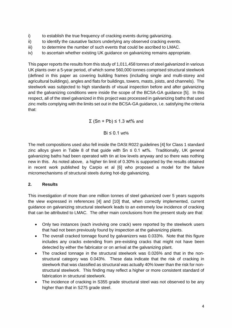
initiate cracking. Distortion of members can also occur due to inadequate venting in steelwork
intended for galvanizing. This problem is illustrated in Figure 11, where smaller and properly
vented members were welded onto a larger section that was not adequately vented. Trapped
internal gases have led to local bulging of the main member in the thermally-affected weld
zone and hence initiated cracking at its junction with the cross-members.
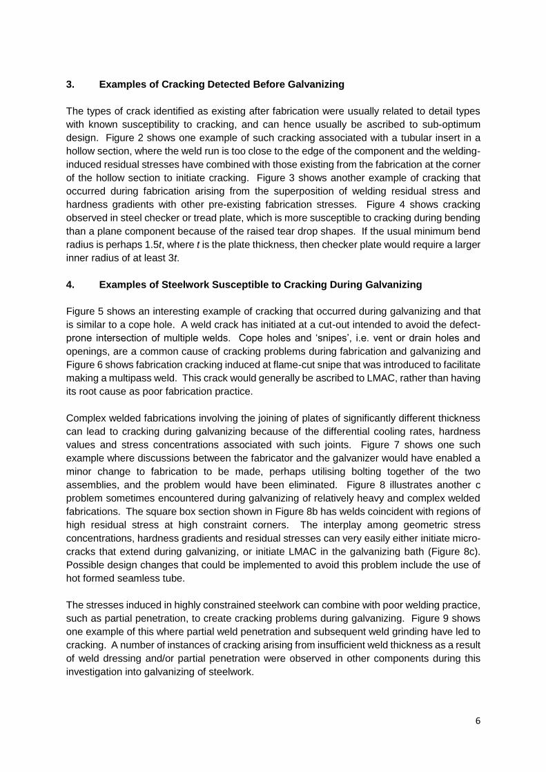
As a final example of the range of problems sometimes experienced during galvanizing, Figure
12 shows cracking in a cold formed rectangular hollow section. The residual stresses induced
in either cold-rolled or welded hollow sections at the corners, tend to increase with increase in
length of the component. Cracking can initiate or extend during galvanizing from either small
defects at the weld ends or local stress concentrations/hard spots at flame cut edges. The
high levels of tensile residual stress that existed in the outer surface are evidenced in the
deformation seen in the plate after cracking.
5. Conclusions
This review of cracking events observed either after fabrication or after hot dip galvanizing, in
>1,000,000 tonnes of steelwork with 560,000 tonnes falling into a structural classification, has
unequivocally demonstrated that such occurrences are extremely rare. The total overall
cracked tonnage was found to be 0.033%, with 0.026% of the structural steel tonnage having
cracks and 0.043% of the non-structural category containing cracks. A visual investigation of
the observed cracking events, as described in this paper, further indicated that the large
majority of cracks were associated with weld zones.
The underlying causes of cracking fell into well-known categories of sub-optimum design,
involving either weld details or design for galvanizing, many of which have already been
described in more detail in reference [9]. This work supports two important conclusions, firstly,
that LMAC cannot accurately be described as a root cause of cracking during galvanizing, but
is rather a factor in further crack propagation where an incipient crack-like defect or crack-
susceptible region already exists in the steelwork to be galvanized; and, secondly, that LMAC
is not an issue when using galvanizing baths with tin (Sn) contents and melts that comply with
the BCSA-GA guidance [5]. Finally, it is clear that liaison with the galvanizing plants during
the design process would eliminate a number of potential cracking problems that can arise
from sub-optimum design for the galvanizing process.
References
[1] M. Feldmann, T. Pinger, D. Schäfer, R. Pope, W. Smith, G. Sedlacek, Hot-dip-zinc coating of prefabricated structural steel components, European Commission, Joint Research Council, 2010, p. 110. [2] Anon, Zinc assisted cracking on big scale steel structure and preventative methods, Tomoe Research & Development Ltd, Tomoe Corporation, Japan, 2001. [3] W.J. Rudd, S.W. Wen, P. Langenberg, B. Donnay, A. Voelling, T. Pinger, M. Feldmann, J. Carpio, J.A. Casado, J.A. Alvarez, F. Gutierrez, EUR 23195 - FAMEGA Failure mechanisms during galvanizing, European Commission, Luxembourg, 2008, p. 138.

8
[4] D.A.f. Stahlbau, DASt Guideline 022: Feuerverzinken von tragenden Stahlbauteilen (Guideline for hot-dip-zinc-coating of prefabricated loadbearing steel components), 2009. [5] Galvanizing Structural Steelwork - An Approach to Management of Liquid Metal Assisted Cracking, British Constructional Steelwork Association and Galvanisers Association, London, 2005. [6] J. Carpio, J.A. Casado, J.A. Álvarez, F. Gutiérrez-Solana, A micromechanical model of the cracking failure on structural steel components during hot-dip galvanizing, Surface and Coatings Technology 286 (2016) 335-346. [7] T.J. Kinstler, Current Knowledge of the Cracking of Steels During Galvanizing, GalvaScience for the American Institute of Steel Construction, 2004, p. 79. [8] G. Poag, J. Zervoudis, Influence of Various Parameters on Steel Cracking during Galvanizing, AGA Technical Forum, Kansas City, 2003. [9] M.N. James, Designing against LMAC in galvanised steel structures, Engineering Failure Analysis 16(4) (2009) 1051-1061. [10] EGGA, Guidance Document: Controlling liquid metal assisted cracking during galvanizing of constructional steelwork, European General Galvanizers Association, Caterham, Surrey, 2014, p. 8.

9
Tensile Stress Specific Material Condition Liquid Metal
Stress concentration (especially welds)
Strength/hardness > 250-290 HV Hydrogen cracking
• Pickling and fluxing of high strength steels
• Flux containing Fe > 10 g/l
• Weld regions with HV > 300-350
Pb: increases incidence and severity of cracking Ni: No effect Sn and Bi > 0.2% increases crack size Sn > 0.3% increases crack size
Residual stress
• Straightening
• Thermal cutting
• Welding
• Cold work
Thermal stress
• Component size
• Dipping speed and angle
Table 1 Factors contributing to the occurrence of liquid metal assisted cracking LMAC.
After Kinstler [7] and as given in reference [3]. Factors in bold are additions
added by the authors.
Location of Crack % % LMAC
Cope hole cut-out and other design issues
10 0
Steel plate, e.g. distortion or material defect
12
5
Weld zone 78
Table 2 Proportion of cracks found in the final 2-year analysis of galvanized steelwork in
terms of their location and the percentage considered to involve LMAC.

10
Figure 1 Venn diagram showing the critical intersection region (red) of the four necessary
conditions defined by Kinstler [7] for the occurrence of LMAC during galvanizing.
Tensile stress
Time
Bath Environment
Specific Sensitivity Condition
Residual Stress Stress Concentrator Thermal Gradients
Steel Composition Thermal History Mechanical History
Galvanizing Time
Alloy Type Alloy Concentration Temperature Additives (flux)

11
Figure 2 Weld run around an insert that was too close to an existing fabrication-induced
region of plasticity/residual stress.
Figure 3 This crack is probably again due to a combination of the welding process
(residual stress and hardness gradients) and the stresses induced during
forming of the cylindrical casing.

12
Figure 4 The cracking seen here is due to the steel checker plate having too tight a bend
radius.
Figure 5 Weld cracking initiated from a small cut-out intended to avoid the problem of
intersecting welds in fabrication of a hollow section.

13
Figure 6 A crack that has initiated at a flame-cut ‘snipe’ intended to facilitate making a
multipass weld. Cracking is due to the high local hardness and stress
concentrations induced during flame cutting.
Figure 7 Cracking at the highly constrained joint between a smaller sub-assembly and a
large I-beam. Separate fabrication of the two components and subsequent
bolting would have eliminated the problem.

14
Figure 8 The complex fabrication shown in a) has square box sections b) where several
welds are coincident at the highly constrained corners. The interplay among
geometric stress concentrations, hardness gradients and residual stresses can
very easily either initiate micro-cracks that extend during galvanizing, or initiate
LMAC in the galvanizing bath
a) b)
c)

15
Figure 9 In this complex welded fabrication, partial weld penetration and subsequent
weld grinding have led to cracking occurring during galvanizing from the under-
sized weld.
Figure 10 Significant distortion has occurred in the highly constrained smaller cross-
members in this steel fabrication, and the off-centre hole has led to an additional
localisation of stress, causing cracking to occur during galvanizing.
16
Figure 11 Inadequate venting provision has led to bulging of the main member in the
thermally weakened zone where the cross-members were welded to it, causing
cracking.
Figure 12 Cracking in a cold formed steel section that has initiated from one end due to
the high levels of residual stresses existing in the cold formed section at the
corners.


