
THE EFFECT OF NAILING PATTERNS ON THETENSILE STRENGTH OF PLYWOOD GUSSETS
J. E. TurnbullMember CSAE
Engineering Research ServiceCanada Department of Agriculture, Ottawa
D. M. ToddEngineering Research Service
Canada Department of Agriculture, Ottawa
Nailed plywood gusset connectionsare widely used in Canada and othercountries for lightweight lumberframes and roof trusses. These framesand trusses are popular in residentialand farm buildings because of economy and simplicity of constructionwith common hand tools. For thispurpose a relatively standard combination of frame and gusset sizes isVfc-inch exterior grade Douglas Firplywood gussets applied to both sidesof 15/8-inch lumber frames. Standard roof truss designs by the CanadaFarm Building Plan Service also usethis connection system, assembledwith special hardened steel nails nowmanufactured in Canada and distributed through a chain of retail lumberyards and several hardware distributors.
When calculating stresses for thedesign of bolted or riveted gusset connections it is customary to considerthe section area of gussets and members to be reduced at least equivalentto the projected area of the connectors. Nailed connections in woodhowever are usually not pre-drilledor pre-punched as are bolted or riveted connections. Therefore with nailed wood connections, the designercustomarily assumes that the nailspart the wood fibers on penetration,and that the member (gusset orframe) remains as strong as beforenailing. With large nails such as theTruss Gusset Nail (0.19-inch majordiameter) used in the Canada FarmBuilding Plan Service trusses, thisassumption may not be justifiable.The purpose of this study was to determine the effect of large-diameterspiral shank nails on the tensilestrength of plywood gussets. Thetests were designed to simulate loading of the connected lower chord ofa typical farm roof truss, where thestresses result mainly from tensionforces, and are not complicated bybending or shear.
Contribution No. 182 from Engineering Research Service, Research Branch, CanadaDepartment of Agriculture, Ottawa, Canada.RECEIVED FOR PUBLICATIONSEPTEMBER 29. 1969
42
LITERATURE REVIEW
The German building code, DIN1052 (4), contains specifications forminimum end, edge, and nail-to-nailspacings, all expressed in nail diameters. Egner (5) commented on thenail spacings specified by DIN 1052,indicating that in general they wereadequate for wood having widelyspaced growth rings, but that thesespacings resulted in excessive splittingin dry wood and wood having narrowgrowth rings (dense wood). Turnbull(9) found that nails with a square-spiral shank produced less splitting inspruce lumber than smooth-shanknails 2 gauge sizes smaller. Stern (8)found, and Turnbull (10) confirmedthat spiral-shank nails, when hardened by heat treatment, would holdgreater lateral loads than smooth-shank nails of equivalent diameter,especially at joint yields approachingfailure where the spiral shank formof the bent nails apparently holds thewood members together better thansmooth nails.
Effects of nailing wet and testingdry specimens, and effects of moisture cycling of specimens before loadtesting, have been noted by Gilbert-son (6) and by Mack (7). Thestrength and stiffness reductions dueto changing moisture (drying) beforetesting are mainly caused by shrinkage of the wood parts in thickness.Since the steel nails connecting thewood parts do not similarly changedimension, a separation or gap appears between the wood faces, thereby removing any possible benefitfrom wood-to-wood friction.
CSA 086 (3) indicates workingstresses for the various grades of firplywood. Plywood Design Fundamentals (2) indicates how to use design stresses, and the nominal designthicknesses of the various plies of theplywood. However, no literature wasfound to indicate plywood tensionstrength reductions due to nail perforations.
PROCEDUREIn Canada, typical yard lumber is
sold and used in a moist (unseasoned) condition, nailed in this moistcondition, and dried in service afterthe structure is roofed and closed.This practice does not achieve thebest possible joint strength, but it isthe common practice; therefore, inCanada, lumber connections shouldbe designed on this basis. For thisreason, and to conform to previoustesting procedure (9), plywood andframe parts for this experiment werepreconditioned to approximately 28percent moisture content, nailed, reconditioned to approximately 12.6percent and then tested. This procedure does not comply with ASTMD 1761 (1) which specifies that lumber parts should be preconditionedtoapproximately 12 percent moisture(dry basis) before connecting.
Figure 1 shows details of the testspecimens. A long, slender multiple-nail joint was designed to force failure to occur at a section where the
3iO.I=Q3IN.EFFECTIVETHICKNESS
PUES1TOTEN90NCONSIDERED TOMAKENOCONTRIBUTION TO
STRENGTH.3i0.l*Q3IN
TOTAL £FFECTIVFA»r*
—— -**i.Jut*15(3 + 3)*.
TYPICAL SECTION AT VW TO SHTiWNAIL PENETRATION AND PLYWOODTENSIONAREA. ~
Figure 1. Details of plywood tensionjoint test specimens.
CANADIAN AGRICULTURAL ENGINEERING, VOL. 12, No. 1, MAY 1970
tension in the plywood gussets couldbe determined (that is, immediatelyadjacent to the butt ends of thespruce center members). This wasnot entirely successful, and resultsfrom two specimens had to be discarded because of premature failureelsewhere.
Nail spacings were based generallyon DIN 1052 (4) except at the sections which were intended to fail. Atthese critical sections, nails were progressively crowded in a line perpendicular to the plywood face grain,in order to assess the plywoodstrength reduction due to nailing.
At the critical sections, A or B, from1 to 5 nails were driven through eachthree-member joint, making 5 treatments, each replicated ten times. Allcritical sections except the one-nailtreatment had nails driven from bothsides; all nails were nominal 2V2-inchand therefore were loaded in doubleshear.
All nails used were Truss Gussetnails made by the Steel Company ofCanada Ltd. These nails are duplicates of the "6-gauge x 2V2-inch,medium hard" type of spiral nailtested by Turnbull (10), except thatthe nail manufacturer's length specification has been changed from 2.5inches plus or minus 1/16-inch, to 2.5inches minus zero plus Vfe-inch. This
slight change ensures a nail of sufficient length to completely penetratethe back gusset (see Figure 1), an aidto positioning nails driven in a secondoperation from the other side.
Nails were hammer-driven underconditions as close as possible to thoseapplying to the on-site fabrication oftrusses with semi-skilled labour. Plywood surface veneers were markedwith the hammer as each nail headwas driven flush, since this type ofdamage could be expected with roughcarpentry.
After conditioning, specimens werepulled to failure at a machine cross-head speed of 0.05 inches per minute.
RESULTS
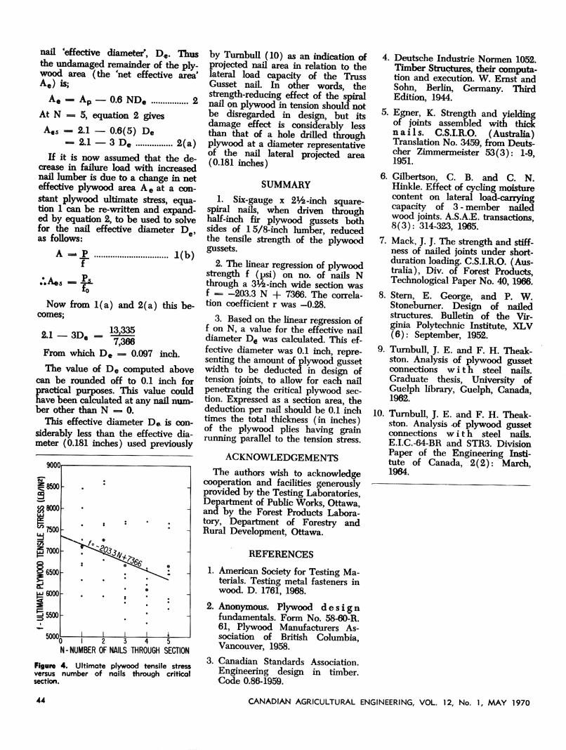
Figure 3 shows typical modes offailure at (a) 2-nail and (b) 3-nailsections. Note the meandering fractures which crossed the nail holes butproceeded unpredictably elsewhere.This characteristic of wood failureprobably accounts for a large part ofthe wide variation in results withineach treatment group.
To show the effect of nailing onplywood strength, figure 4 was prepared, with number of nails Nthrough the critical section on thehorizontal scale, and ultimate plywood tensile stress f on the vertical.Ultimate plywood stress was calculated by the following:
f 1
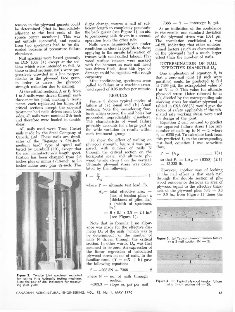
Figure 2. Tension joint specimen mountedfor testing in a hydraulic testing machine.Note the pair of dial indicators for measuring joint yield.
where P = ultimate test load, lb.
Ap= total effective area =(no. of tension plies) x(thickness of plies, in.)x (width of specimen,in.)
= 6 x 0.1 x 3.5 — 2.1 in.2(see Figure 1).
Note that in formula 1 no allowance was made for the effective diameter De of the nails (which was tobe determined), or the number ofnails N driven through the criticalsection. In other words, De was firstassumed to be zero. An expression ofthe linear regression of calculatedplywood stress on no. of nails, in thefamiliar form, (Y = mX + b) gavethe following equation:
f = -203.3N + 7366 2
where N = no. of nails throughsection
—203.3 = slope m, psi per nail
CANADIAN AGRICULTURAL ENGINEERING, VOL. 12, No. 1, MAY 1970
7366 = Y — intercept b, psi.
As an indication of the confidencein the results, one standard deviationof the plywood stress was 1031 psi.The correlation coefficient r was—0.28, indicating that other undetermined factors (such as characteristicsof the plywood) had a much largereffect than the number of nails.
DETERMINATION OF NAILEFFECTIVE DIAMETER De
One implication of equation 2, isthat a zero-nail joint (if such werepossible) could be predicted to failat 7366 psi, the extrapolated value off at N = 0. This value for ultimateplywood stress (later referred to asf0), divided by the corresponding safeworking stress for similar plywood astabled in CSA 086(3) would give thefactor of safety applicable if the tabulated safe working stress were usedfor design of the joint.
Equation 2 can be used to predictthe apparent failure stress f for anynumber of nails up to N = 5, wheref5 = 6350 psi. To calculate back fromthis predicted fs to the correspondingtest load, equation 1 was re-writtenthus;
P = fA, 1(a)
so that P5 — f5Ap — (6350) (2.1)= 13,335 lb.
However, another way of lookingat the nail effect is that each nailthrough the double section of plywood removes or destroys an area ofplywood equal to the effective thickness of the plywood plies (0.3 + 0.3= 0.6 in., from Figure 1) times the
Figure 3. (a) Typical plywood tension failureat a 2-nail section (N =»» 2).
Figure 3. (b) Typical plywood tension failureat a 3-nail section (N = 3).
43
nail effective diameter, De. Thusthe undamaged remainder of the plywood area (the 'net effective area'Ae) is;
Ae -. Ap — 0.6 NDe 2
At N = 5, equation 2 gives
A€5 _ 2.1 — 0.6(5) De— 2.1 — 3 D« 2(a)
If it is now assumed that the decrease in failure load with increasednail lumber is due to a change in neteffective plywood area Ae at a constant plywood ultimate stress, equation 1 can be re-written and expanded by equation 2, to be used to solvefor the nail effective diameter De,as follows:
A - P. .f
to
1(b)
Now from 1(a) and 2(a) this becomes;
2.1 — 3De — 13,335
7,366From which De — 0.097 inch.
The value of De computed abovecan be rounded off to 0.1 inch forpractical purposes. This value couldhave been calculated at any nail number other than N = 0.
This effective diameter De is considerably less than the effective diameter (0.181 inches) used previously
9000
44
0 I 2 3 4 5"
N-NUMBER OF NAILS THROUGH SECTION
Figure 4. Ultimate plywood tensile stressversus number of nails through criticalsection.
by Turnbull (10) as an indication ofprojected nail area in relation to thelateral load capacity of the TrussGusset nail. In other words, thestrength-reducing effect of the spiralnail on plywood in tension should notbe disregarded in design, but itsdamage effect is considerably lessthan that of a hole drilled throughplywood at a diameter representativeof the nail lateral projected area(0.181 inches)
SUMMARY
1. Six-gauge x 2V^-inch square-spiral nails, when driven throughhalf-inch fir plywood gussets bothsides of 15/8-inch lumber, reducedthe tensile strength of the plywoodgussets.
2. The linear regression of plywoodstrength f (psi) on no. of nails Nthrough a 3^-inch wide section wasf _ -203.3 N + 7366. The correlation coefficient r was —0.28.
3. Based on the linear regression off on N, a value for the effective naildiameter De was calculated. This effective diameter was 0.1 inch, representing the amount of plywood gussetwidth to be deducted in design oftension joints, to allow for each nailpenetrating the critical plywood section. Expressed as a section area, thededuction per nail should be 0.1 inchtimes the total thickness (in inches)of the plywood plies having grainrunning parallel to the tension stress.
ACKNOWLEDGEMENTS
The authors wish to acknowledgecooperation and facilities generouslyprovided by the Testing Laboratories,Department of PublicWorks, Ottawa,and by the Forest Products Laboratory, Department of Forestry andRural Development, Ottawa.
REFERENCES
1. American Society for Testing Materials. Testing metal fasteners inwood. D. 1761, 1968.
2. Anonymous. Plywood designfundamentals. Form No. 58-60-R.61, Plywood Manufacturers Association of British Columbia,Vancouver, 1958.
3. Canadian Standards Association.Engineering design in timber.Code 0.86-1959.
4. Deutsche Industrie Normen 1052.Timber Structures, theircomputation and execution. W. Ernst andSohn, Berlin, Germany. ThirdEdition, 1944.
5. Egner, K. Strength and yieldingof joints assembled with thicknails. C.S.I.R.O. (Australia)Translation No. 3459, from Deuts-cher Zimmermeister 53(3): 1-9,1951.
6. Gilbertson, C. B. and C. N.Hinkle. Effect of cycling moisturecontent on lateral load-carryingcapacity of 3-member nailedwood joints. A.S.A.E. transactions,8(3): 314-323, 1965.
7. Mack, J. J. The strength and stiffness of nailed joints under short-duration loading. C.S.I.R.O. (Australia), Div. of Forest Products,Technological Paper No. 40, 1966.
8. Stern, E. George, and P. W.Stoneburner. Design of nailedstructures. Bulletin of the Virginia Polytechnic Institute, XLV(6): September, 1952.
9. Turnbull, J. E. and F. H. Theak-ston. Analysis of plywood gussetconnections with steel nails.Graduate thesis, University ofGuelph library, Guelph, Canada,1962.
10. Turnbull, J. E. and F. H. Theak-ston. Analysis -of plywood gussetconnections with steel nails.E.I.C.-64-BR and STR3. DivisionPaper of the Engineering Institute of Canada, 2(2): March,1964.
CANADIAN AGRICULTURAL ENGINEERING, VOL. 12, No. 1, MAY 1970


