
METU Civil Engineering Department CE 272 FLUID MECHANICS
2.01
HYDROSTATICS
Body Forces: External forces distributed over the mass of the
fluid developed without physical contact.
kBjBiBB zyx Body force
In case of gravity being the sole body force acting:
kmgkWkBB z
Surface Forces: Forces acting on any surface defined in the
fluid.
Stress at a point:
m
F
A
x
z Ax=ABO
Ay=BCO
Az=ACO
O A
B
kFjFiFF zyx
kAjAiAA zyx
A
Flim)(Stress
0A
y
C
Given that z and g
Inertia force )kajaia(mF zyxi

METU Civil Engineering Department CE 272 FLUID MECHANICS
2.02
Stress Tensor:
yy
x
yz
yx
xy
xz
xx
zz
zy
zx
zzzyzx
yzyyyx
xzxyxx
Stress tensor is symmetrical
zyyz
zxxz
yxxy
z
y
METU Civil Engineering Department CE 272 FLUID MECHANICS
2.03
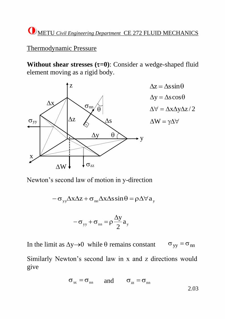
Thermodynamic Pressure
Without shear stresses (=0): Consider a wedge-shaped fluid
element moving as a rigid body.
x
y
z
nn
yy
zz
y
z
x
s
sinsz
cossy
2/zyx
W
W
Newton’s second law of motion in y-direction
ynnyy asinsxzx
ynnyy a2
y
In the limit as y0 while remains constant nnyy
Similarly Newton’s second law in x and z directions would
give
nnxx nnzz and
METU Civil Engineering Department CE 272 FLUID MECHANICS
2.04
That is
In the absence of shear stresses the normal stress in a fluid is
independent of orientation of the plane thus can be represented
by a single scalar quantity. Taking the fact that fluids can
sustain only compression, pressure p is set equal to negative of
this magnitude:
pzzyyxx
With shear stresses (0):
The bulk stress )(3
1zzyyxx
is independent of rotation of coordinate axes and known as
pressure
p
σxx = σyy = σzz = σnn

METU Civil Engineering Department CE 272 FLUID MECHANICS
2.05
PRESSURE FORCE per UNIT VOLUME
The Gradient of Pressure:
Consider a pressure field acting on an infinitesimal frictionless
fluid element moving as a rigid body or at rest (=0)
y
z
x
dyy
pp
p
The net pressure force in y-direction is
dy dx
dz
d
y
pdxdydz
y
pdxdzdy
y
pppdF
Py
The force vector due to
pressure variations in
x, y and z directions
dk
z
pj
y
pi
x
pFd
P
The pressure force per unit volume
gradppfkz
pj
y
pi
x
p
d
FdP
P
kz
jy
ix
The Gradient operator
METU Civil Engineering Department CE 272 FLUID MECHANICS
2.06
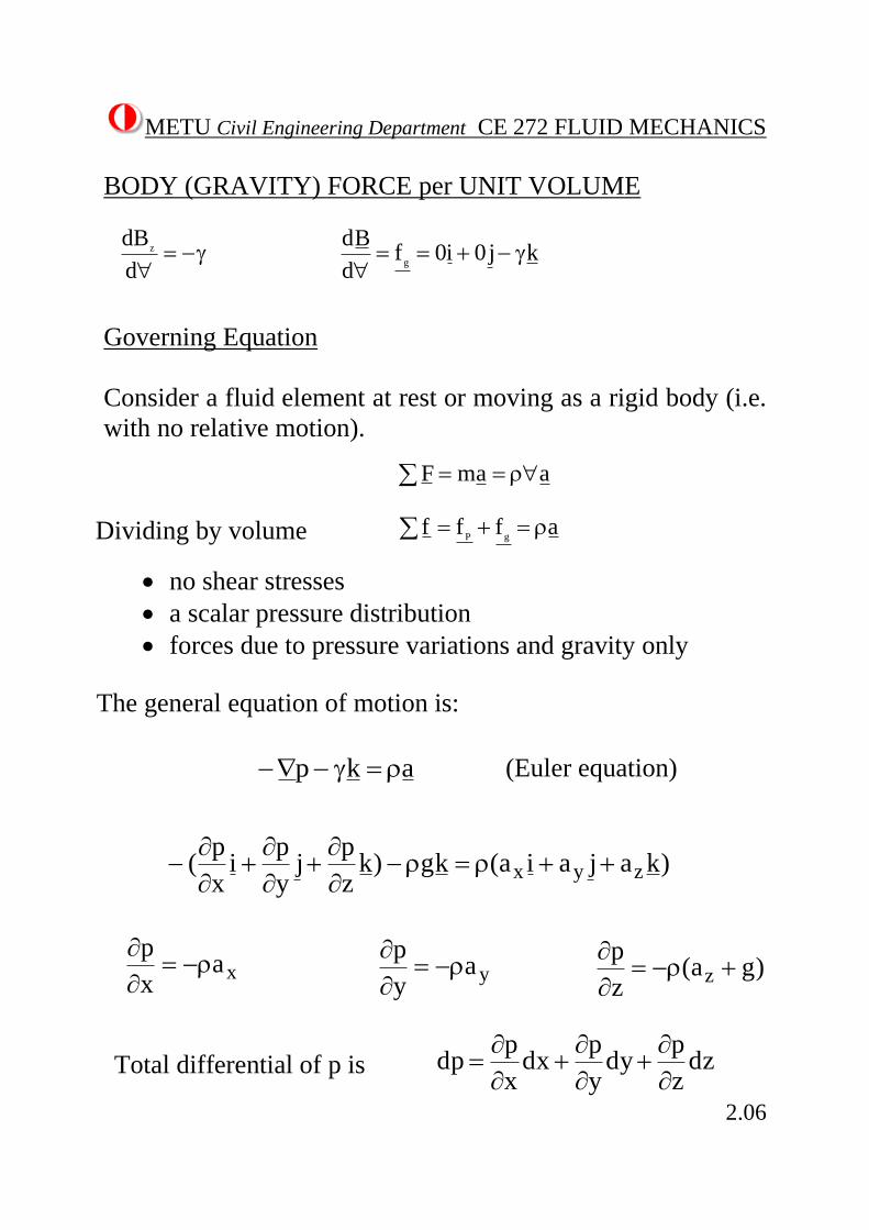
BODY (GRAVITY) FORCE per UNIT VOLUME
Governing Equation
Consider a fluid element at rest or moving as a rigid body (i.e.
with no relative motion).
no shear stresses
a scalar pressure distribution
forces due to pressure variations and gravity only
aamF
Dividing by volume afffgP
The general equation of motion is:
akp
)kajaia(kg)kz
pj
y
pi
x
p( zyx
xax
p
ya
y
p
)ga(
z
pz
(Euler equation)
d
dBz
kj0i0fd
Bdg
Total differential of p is dzz
pdy
y
pdx
x
pdp
METU Civil Engineering Department CE 272 FLUID MECHANICS
2.07
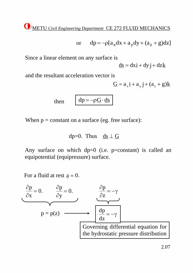
Since a linear element on any surface is
kdzjdyidxds
then dsGdp
When p = constant on a surface (eg. free surface):
and the resultant acceleration vector is
k)ga(jaiaG zyx
dp=0. Thus ds G
Any surface on which dp=0 (i.e. p=constant) is called an
equipotential (equipressure) surface.
.0x
p
.0
y
p
z
p
p = p(z)
Governing differential equation for
the hydrostatic pressure distribution
dz
dp
For a fluid at rest .0a
]dz)ga(dyadxa[dp zyx or

METU Civil Engineering Department CE 272 FLUID MECHANICS
2.08
Pressure distribution in an incompressible fluid at rest or
moving as a rigid body with no acceleration
z
z
zs
p
patm
d
dz
dp
satmz
z
P
P
dzdp
d)zz(pp satm
dppp atmabsolute dppp atmabsolutegauge
z patm
gauge
pressure
absolute
pressure
w
Measurement of Pressure
Barometer
h patm
pv
hp
.0p
hpp
matm
v
mvatm
m
Pre
ssure
Local
atmospheric
pressure +gauge
-gauge
Absolute zero p

METU Civil Engineering Department CE 272 FLUID MECHANICS
2.09
Manometers
hpp atmA
Piezometer
A1w2matm phhp
A
h1 h2 m
w
patm
U-tube manometer
Differential manometer
A
B
h1 h3
h2
1
2
3
332211AB hhhpp
A
patm
h
Inclined manometer
pA
L
x
h
patm
B332211A phhhp

METU Civil Engineering Department CE 272 FLUID MECHANICS
2.10
Hydrostatic Forces on Plane Surfaces
hp
hc
dF
dA c
cp
F
y
y yc
yp
xc
xp
x
o
o
hdApdAdF
dAhFA
A
dAsiny
A
ydAsin
AhAysin cc
ApF c
dAysindAsinyyydFdMFyMA
2
AAA opo
Ay
Iy
Ay
AyI
Ay
I
ydAθsinγ
dAyθsinγ
F
ydFy
c
xcc
c
2cxc
c
xx
A
A2
Ap
Ay
Ix
Ay
AyxI
Ay
I
ydAsin
xydAsin
F
xdFx
c
xycc
c
ccxyc
c
xy
A
Ap
h
y

METU Civil Engineering Department CE 272 FLUID MECHANICS
2.11
Pressure prism concept
The pressure prism is a geometric representation of the
hydrostatic force on a rectangular plane surface
FR
p
h1
h2 FR cp
b
h1
h2
The magnitude of the resultant hydrostatic force is equal to the
volume of the pressure prism and passes through its centroid.
FR = F1 + F2 = pcA
F1 = h1(h2-h1)b b)hh(2
)hh(F 12
122
h1 (h2-h1)
F2 F1 +

METU Civil Engineering Department CE 272 FLUID MECHANICS
2.12
Hydrostatic Forces on Curved Surfaces
dF = p dA
dFx = p dAx
The horizontal component of the hydrostatic force on a curved
surface is the product of the pressure at the centroid with the
area projection on a vertical plane.
z
y
x
dAx
dAy
dAz
h
zs
dA dFz = p dAz
dFy = p dAy
p
dA
x
z
pdAcos
xx pdAcospdAdF
xcA xx AppdAF
ycA yy AppdAF
Horizontal components:
p
dA
y
z
pdAcos
yy pdAcospdAdF
METU Civil Engineering Department CE 272 FLUID MECHANICS
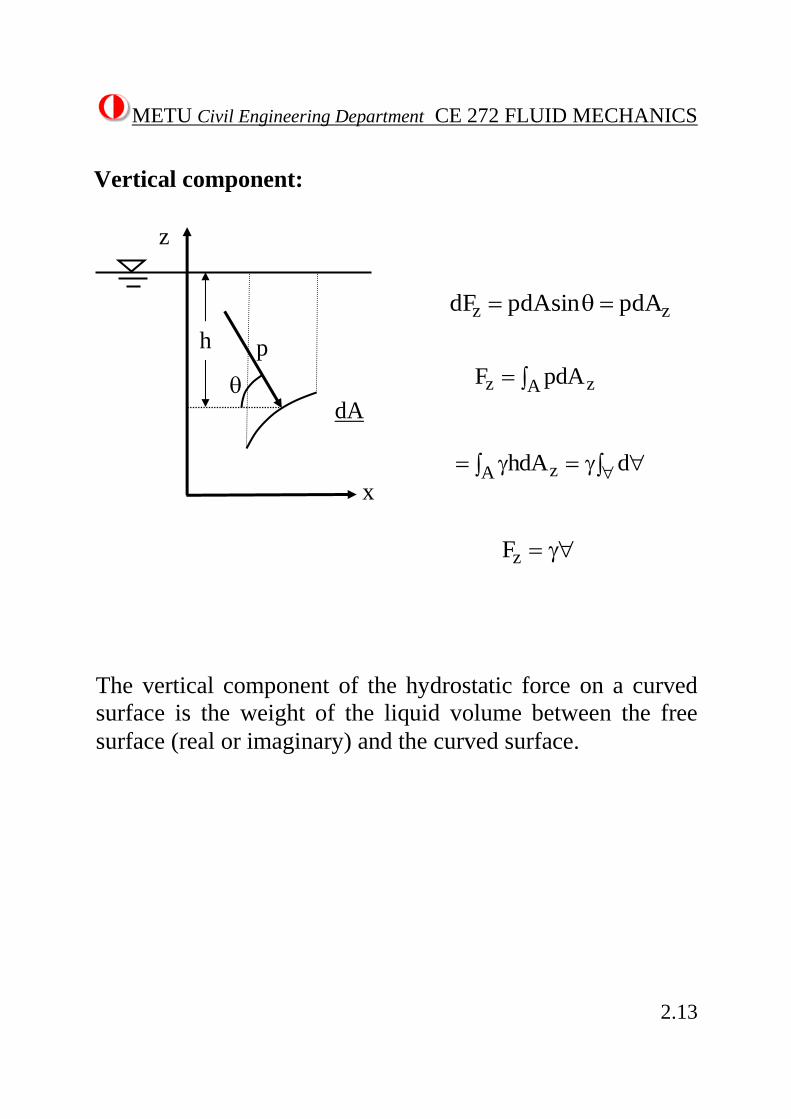
2.13
The vertical component of the hydrostatic force on a curved
surface is the weight of the liquid volume between the free
surface (real or imaginary) and the curved surface.
p
x
z
zz pdAsinpdAdF
h
A zz pdAF
ddAh zA
zF
dA
Vertical component:

METU Civil Engineering Department CE 272 FLUID MECHANICS
2.14
Buoyancy and Flotation
The lifting force due to hydrostatic pressure distribution on
submerged volumes is called as ‘buoyant force’.
h
p1
p2
dFB=(p2-p1)dAz
z
Az12B dA)hh(F
z
Az12 dA)hh(
FB = submerged
The buoyant force acts through the
center of gravity of the submerged
volume in a direction opposite to
that of gravitation.
The same result apply to
floating bodies which are
only partially submerged FB
W = FB
cp
W
cg
z
METU Civil Engineering Department CE 272 FLUID MECHANICS
2.15
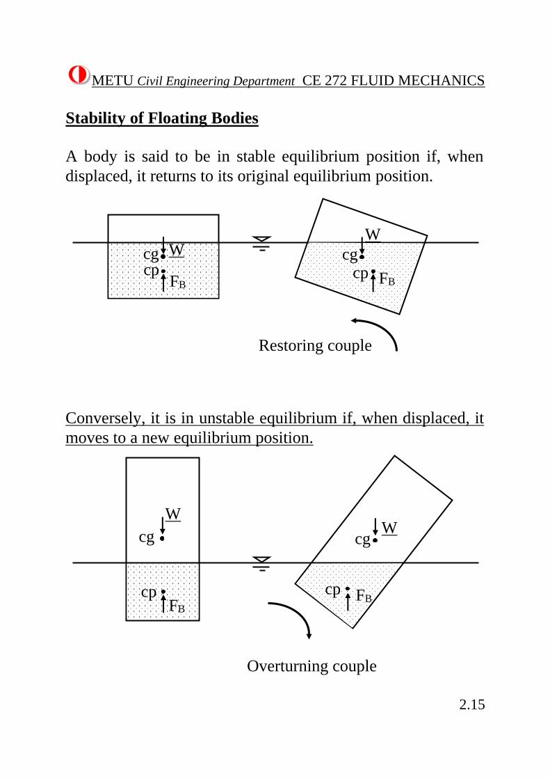
Stability of Floating Bodies
A body is said to be in stable equilibrium position if, when
displaced, it returns to its original equilibrium position.
Conversely, it is in unstable equilibrium if, when displaced, it
moves to a new equilibrium position.
cg cp
W
FB cp FB
W
cg
Restoring couple
cg
cp
W
FB
W cg
Overturning couple
cp FB
METU Civil Engineering Department CE 272 FLUID MECHANICS
2.E01
EXAMPLES
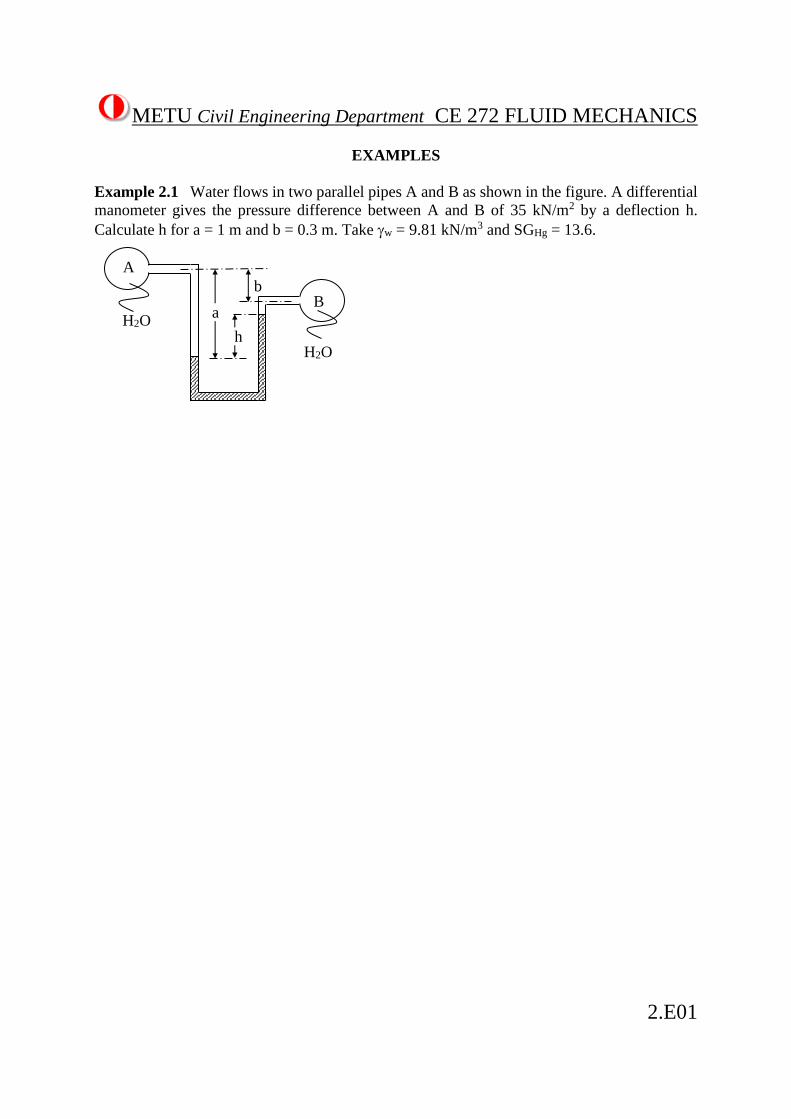
Example 2.1 Water flows in two parallel pipes A and B as shown in the figure. A differential
manometer gives the pressure difference between A and B of 35 kN/m2 by a deflection h.
Calculate h for a = 1 m and b = 0.3 m. Take w = 9.81 kN/m3 and SGHg = 13.6.
A
H2O
H2O
B a
b
h
METU Civil Engineering Department CE 272 FLUID MECHANICS
2.E02
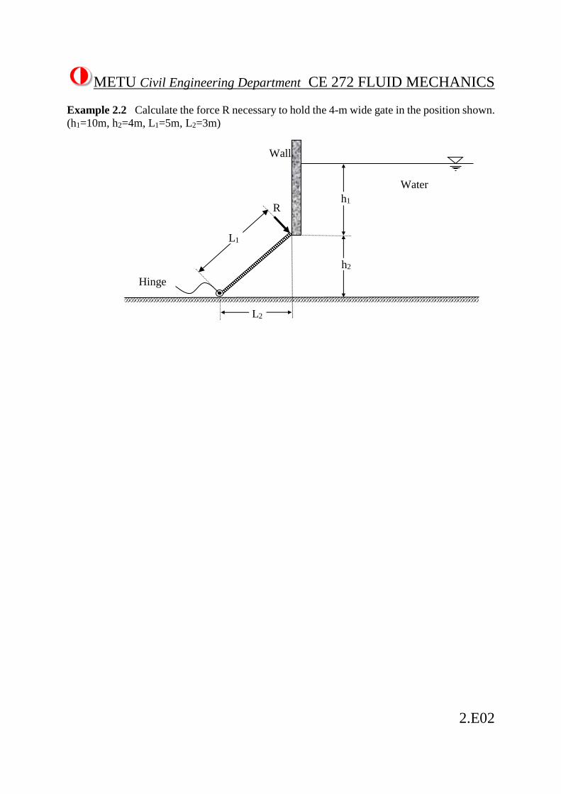
Example 2.2 Calculate the force R necessary to hold the 4-m wide gate in the position shown.
(h1=10m, h2=4m, L1=5m, L2=3m)
h1
Water
Gat
e
Wall
L2
h2
Hinge
R
L1
METU Civil Engineering Department CE 272 FLUID MECHANICS
2.E03
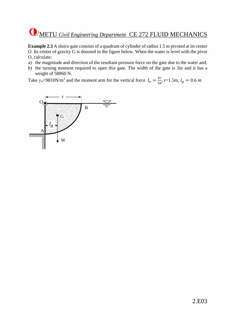
Example 2.3 A sluice gate consists of a quadrant of cylinder of radius 1.5 m pivoted at its center
O. Its center of gravity G is denoted in the figure below. When the water is level with the pivot
O, calculate:
a) the magnitude and direction of the resultant pressure force on the gate due to the water and,
b) the turning moment required to open this gate. The width of the gate is 3m and it has a
weight of 58860 N.
Take w=9810N/m3 and the moment arm for the vertical force 𝑙𝑣 =4𝑟
3𝜋, r=1.5m, 𝑙𝑔 = 0.6 𝑚
A
W
G
𝑙𝑔
B
r O
METU Civil Engineering Department CE 272 FLUID MECHANICS
2.E04
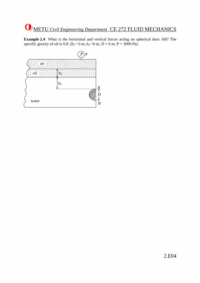
Example 2.4 What is the horizontal and vertical forces acting on spherical door AB? The
specific gravity of oil is 0.8. (h1 =3 m, h2 =6 m, D = 6 m, P = 3000 Pa).
A
water
h1
air
oil
P
B
h2
D
METU Civil Engineering Department CE 272 FLUID MECHANICS
2.E05
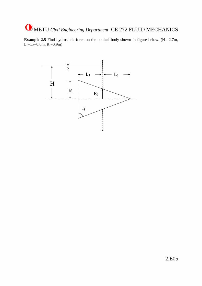
Example 2.5 Find hydrostatic force on the conical body shown in figure below. (H =2.7m,
L1=L2=0.6m, R =0.9m)
H
L1 L2
R
R0
METU Civil Engineering Department CE 272 FLUID MECHANICS
2.H01
HOMEWORK PROBLEMS
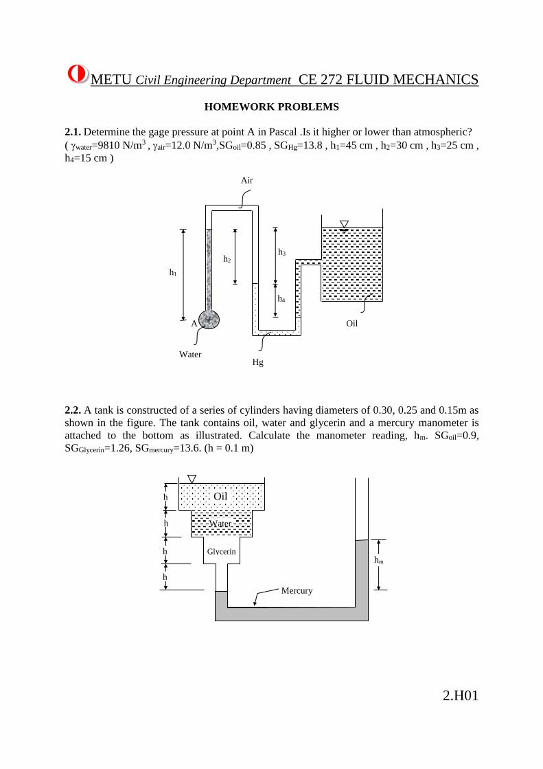
2.1. Determine the gage pressure at point A in Pascal .Is it higher or lower than atmospheric?
( water=9810 N/m3 , air=12.0 N/m3,SGoil=0.85 , SGHg=13.8 , h1=45 cm , h2=30 cm , h3=25 cm ,
h4=15 cm )
2.2. A tank is constructed of a series of cylinders having diameters of 0.30, 0.25 and 0.15m as
shown in the figure. The tank contains oil, water and glycerin and a mercury manometer is
attached to the bottom as illustrated. Calculate the manometer reading, hm. SGoil=0.9,
SGGlycerin=1.26, SGmercury=13.6. (h = 0.1 m)
Water Hg
Oil
Air
h1
h2 h3
h4
A
hm
Mercury
h
h
h
h Glycerin
Oil
Water
METU Civil Engineering Department CE 272 FLUID MECHANICS
2.H02
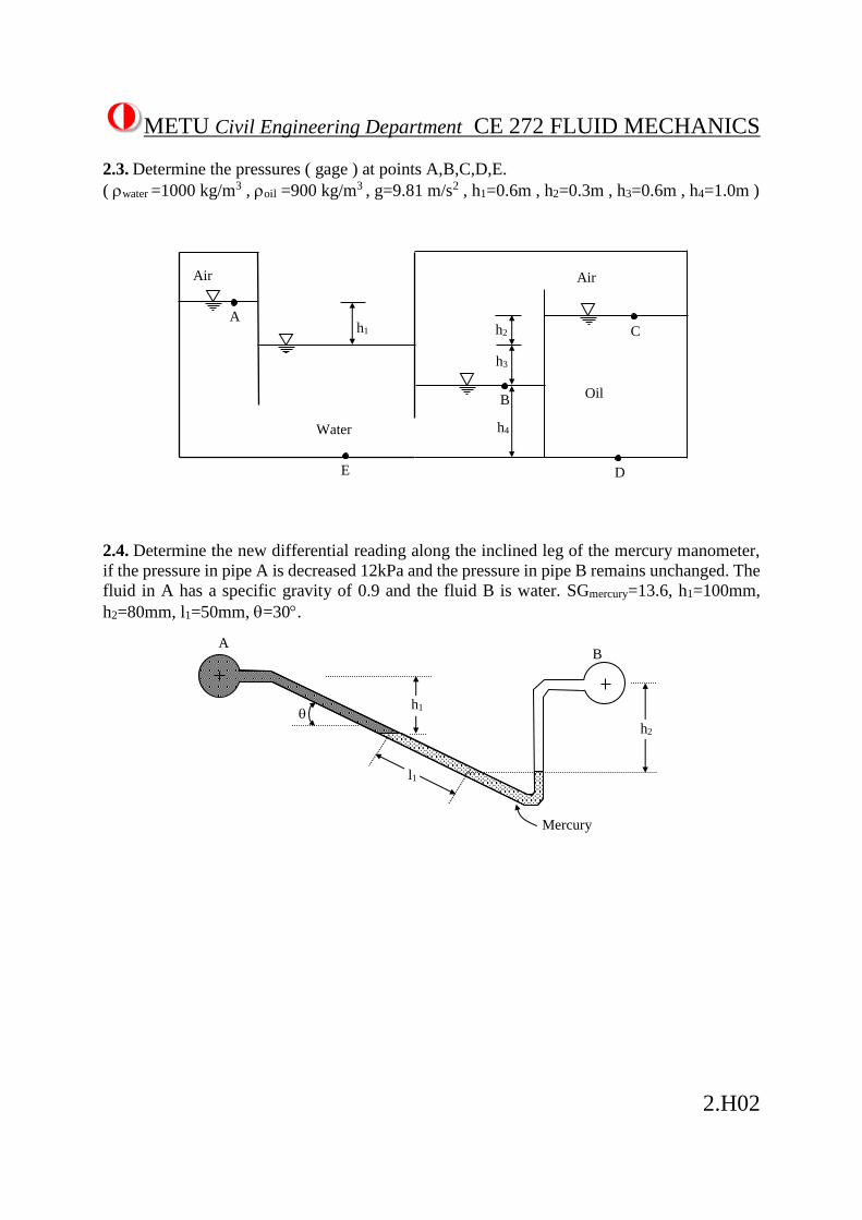
2.3. Determine the pressures ( gage ) at points A,B,C,D,E.
( water =1000 kg/m3 , oil =900 kg/m3 , g=9.81 m/s2 , h1=0.6m , h2=0.3m , h3=0.6m , h4=1.0m )
2.4. Determine the new differential reading along the inclined leg of the mercury manometer,
if the pressure in pipe A is decreased 12kPa and the pressure in pipe B remains unchanged. The
fluid in A has a specific gravity of 0.9 and the fluid B is water. SGmercury=13.6, h1=100mm,
h2=80mm, l1=50mm, =30.
Water
B
C
Oil
Air
D
Air
h2
h3
h1
h4
A
E
h1
A B
Mercury
l1
h2
METU Civil Engineering Department CE 272 FLUID MECHANICS
2.H03
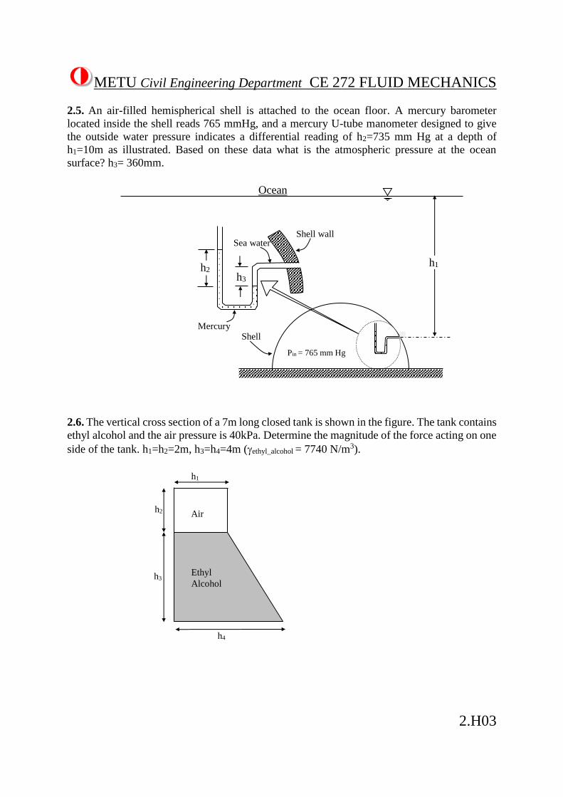
2.5. An air-filled hemispherical shell is attached to the ocean floor. A mercury barometer
located inside the shell reads 765 mmHg, and a mercury U-tube manometer designed to give
the outside water pressure indicates a differential reading of h2=735 mm Hg at a depth of
h1=10m as illustrated. Based on these data what is the atmospheric pressure at the ocean
surface? h3= 360mm.
2.6. The vertical cross section of a 7m long closed tank is shown in the figure. The tank contains
ethyl alcohol and the air pressure is 40kPa. Determine the magnitude of the force acting on one
side of the tank. h1=h2=2m, h3=h4=4m (ethyl_alcohol = 7740 N/m3).
Air
Ethyl
Alcohol
h1
h2
h4
h3
Ocean
Surface
h1
h3
h2
Mercury
Shell wall Sea water
Shell
Pin = 765 mm Hg

METU Civil Engineering Department CE 272 FLUID MECHANICS
2.H04
2.7. The concrete dam given below rests on a solid foundation. The unit weight of concrete is
23.6 kN/m3. Determine the minimum coefficient of friction between the dam and the foundation
required keeping the dam from sliding at the water depth shown. Assume no fluid uplift pressure
along the base. Base your analysis on a unit length of the dam. h1 =4m, h2=5m, h3=6m, h4=2m.
2.8. Calculate the force F necessary to hold the 4 m-wide gate AB in position shown in the
figure below. The specific of oil is 0.8. ( H1=3m, H2=2.6m, H3=4m, P=49.05 kPa, L=5m)
Water h1
h2
h3
h4
hinge
H3
H1
H2
F
B
A
Water
Oil
Air
P
L
METU Civil Engineering Department CE 272 FLUID MECHANICS
2.H05
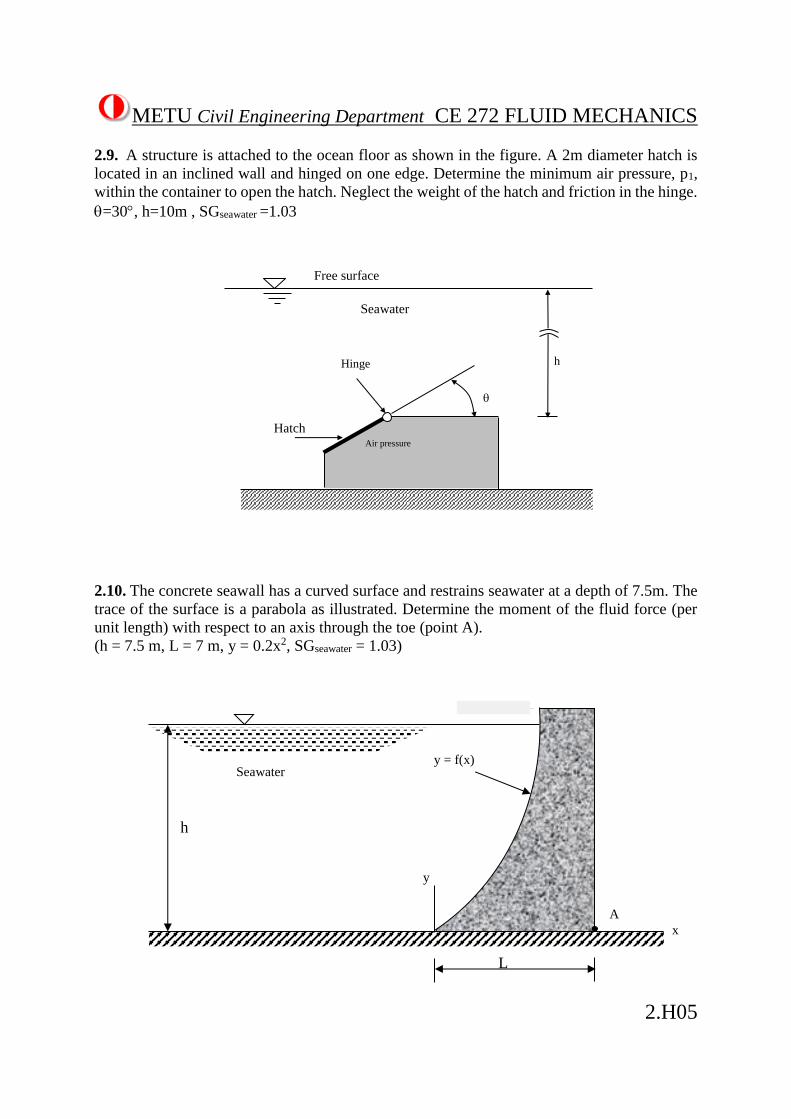
2.9. A structure is attached to the ocean floor as shown in the figure. A 2m diameter hatch is
located in an inclined wall and hinged on one edge. Determine the minimum air pressure, p1,
within the container to open the hatch. Neglect the weight of the hatch and friction in the hinge.
=30, h=10m , SGseawater =1.03
2.10. The concrete seawall has a curved surface and restrains seawater at a depth of 7.5m. The
trace of the surface is a parabola as illustrated. Determine the moment of the fluid force (per
unit length) with respect to an axis through the toe (point A).
(h = 7.5 m, L = 7 m, y = 0.2x2, SGseawater = 1.03)
Hinge
Air pressure
Hatch
Seawater
Free surface
h
x
L
Seawater
A
y = f(x)
y
h

METU Civil Engineering Department CE 272 FLUID MECHANICS
2.H06
2.11. The gate ABC , shown in the figure below , is weightless and has 1 m length in the normal
direction to the figure. Its lower part (BC) is semi-cylindrical in shape .As water rises at the
left-hand-side , the gate will open automatically. At what depth , h , above the hinge this will
occur ? ( water=9.81kN/m3 )
2.12. Find hydrostatic force on the conical body shown in figure below. (H =2.7m,
L1=L2=0.6m, R =0.9m)
H
L1
L2
R
H2O
R C B
A
h
hinge

METU Civil Engineering Department CE 272 FLUID MECHANICS
2.H07
2.13. The cylinder of weight W is in equilibrium as seen in figure below. The length and radius
of the cylinder are L=5 m and R=2 m , respectively , w = 9810 N/m3 Compute;
a) the weight of the cylinder W and
b) the horizontal force exerted at point B due to the cylinder.
2.14. Find the vertical component of the hydrostatic force on hemispherical dome ABC if gage
pressure at D is 90 kPa, R = 1.5 m, L = 2 m and = 15 kN/m3.
R
B
L
D
A
B
C R

METU Civil Engineering Department CE 272 FLUID MECHANICS
2.H08
2.15. A plug in the bottom of pressurized tank is conical in shape as shown in the figure. The
air pressure is 50kPa and the liquid in the tank has a specific weight of 27kN/m3. Determine the
magnitude, direction and line of action of the force exerted on the curved surface of the cone
within the tank due to 50kPa pressure and the liquid.
(h1 = 1 m, h2 = 3 m, Pair = 50 kPa, = 60)
2.16. A 3-m-long curved gate is located in the side of a reservoir containing water as shown in
the figure below. Determine the magnitude of the horizontal and vertical components of the
force of the water on the gate. Show that this force passes through point A.( h=6m , r =2m )
F
Air
Pair
h1
h2
r
A
h
gate
METU Civil Engineering Department CE 272 FLUID MECHANICS
2.H09
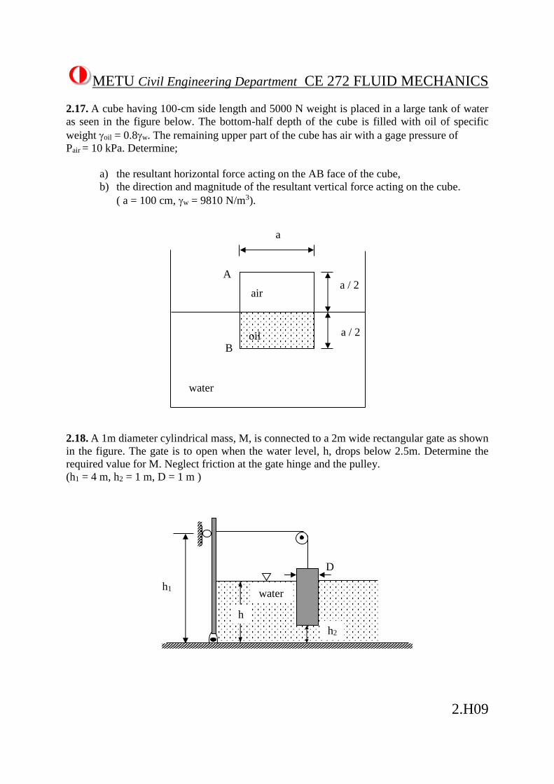
2.17. A cube having 100-cm side length and 5000 N weight is placed in a large tank of water
as seen in the figure below. The bottom-half depth of the cube is filled with oil of specific
weight oil = 0.8w. The remaining upper part of the cube has air with a gage pressure of
Pair = 10 kPa. Determine;
a) the resultant horizontal force acting on the AB face of the cube,
b) the direction and magnitude of the resultant vertical force acting on the cube.
( a = 100 cm, w = 9810 N/m3).
2.18. A 1m diameter cylindrical mass, M, is connected to a 2m wide rectangular gate as shown
in the figure. The gate is to open when the water level, h, drops below 2.5m. Determine the
required value for M. Neglect friction at the gate hinge and the pulley.
(h1 = 4 m, h2 = 1 m, D = 1 m )
a
a / 2
a / 2
A
B
water
oil
air
D
h
h1
h2
water


