
The Solar Water Heater

2
© SmartPower4All.com All rights reserved
PROTECTED BY COPYSCAPE DO NOT COPY
Table of Contents
1. Introduction ............................................................................... 4
2. How much hot water do we use ............................................... 6
3. How much energy do we need to heat our water .................. 7
4. It’s time to turn back to the sun .............................................. 9
5. Water Heater System Types .................................................. 13
6. Location and position of your Solar Water Heater ............. 14
7. Building your Solar Water Heater ........................................ 15
- Parts of the Solar Water Heater ................................ 16
- How it works ................................................................ 17
- Construction of the Collectors ................................... 19
1. Absorber ................................................................. 19
- Preparing the galvanised pipe ........................... 19
- Build the pipe bending device ........................... 20
- Constructing the wooden frame ........................ 21
- Prepare the pipe bending device ....................... 23
- The pipe bending process .................................. 26
- Cutting the galvanized sheet ............................. 33
- Prepare to join the pipe and the sheet .............. 33
- Connecting the pipe and sheet .......................... 35
- Conecting by soldering ...................................... 36
- Constructing the wooden support .................... 37
- Prepare the soldering ......................................... 38
- The soldering procedure .................................... 40
- Painting the absorber ......................................... 43
2. Collector Box .......................................................... 43
3. Insulation layer ...................................................... 47
4. Glass Cover ............................................................ 48
- The Storage tank ......................................................... 51
The soldering ............................................................... 53

3
© SmartPower4All.com All rights reserved
PROTECTED BY COPYSCAPE DO NOT COPY
Insulation of the storage tank ................................. 55
The metal envelope and the cap ............................. 56
- The Buffer tank. ....................................................... 57
8. The installation of the Solar Water Heater ....................... 59
- Foundation ................................................................ 59
- Placing the Collectors .............................................. 61
- Placing the storage tank .......................................... 63
- Testing the hot water system ................................... 63
- The insulation of pipe-connections ......................... 64
- Other collector set-ups ............................................. 65
9. Maintenance ......................................................................... 66
- Checking enclosed air in the system ............................... 66
- Checking dust .................................................................... 67
10. Conclusion........................................................................... 68

4
© SmartPower4All.com All rights reserved
PROTECTED BY COPYSCAPE DO NOT COPY
Introduction
Free and natural! It’s how you always
wanted your hot water! The sun can turn
your dream into a pure fact!
Using energy from the sun to heat water
is one of the oldest uses of solar energy!
Today, millions of homes and businesses
around the globe use solar water heating
systems.
The sun provides enough energy to meet
the world’s energy needs for a whole
year in less than one hour. Why depend
on others? You can put that kind of energy to work in your home with
a reliable, energy-efficient water heater built by you. Watch your
power bills shrink, knowing that you’re capturing one of nature’s
purest sources of energy for your home.
This book will guide you step by step through building a Solar Water
Heater for you and your family. Designed correctly, this system has
proved to be very efficient and we hope you will also have fun putting
it all together.
Why a Solar Water Heater?
1. Sparing Money: Because of major global economic troubles, every
house owner faces the task to cut down costs in different areas of life.
A major part of related to keep a home is the amount expended on
heating water supply for day by day usage.
2. Becoming more independent of energy suppliers: Conventional
sources of energy are finite and the charges for fossil fuels will raise
noticeable in the long run. Furthermore energy companies often abuse
their dominant position in additional surcharges. It is a big great
5
© SmartPower4All.com All rights reserved
PROTECTED BY COPYSCAPE DO NOT COPY
reward to link up oneself to a natural and possibly endless source, the
sunlight.
3. Helping the environment: By burning fossil fuels the emission of
carbon dioxide is a inevitable process. This fact supports the global
warming and the greenhouse effect. Using a self-made heater you can
help personally to stop dangerous exploitation.
4. Easy and inexpensive installation: To assemble a solar water
heater only a couple of comparatively cheap and easy to aquire
materials are necessary.
5. Gaining knowledge and skills: Eventually it is fun to build a solar
water heater system and you can learn a lot, improve your mechanical
skills and get insight to simple yet reliable physical principles.

6
© SmartPower4All.com All rights reserved
PROTECTED BY COPYSCAPE DO NOT COPY
How much hot water do we use
Every time we take a shower we use about 10 gallons of hot water.
Whenever we take a bath we use at least that much — often more. An
average clothes washer uses 22 gallons of hot water per regular
washing cycle, and an automatic dishwasher uses about 15 gallons —
which, by the way, can be more hot water than it takes to wash dishes
in the sink by hand.
Each time we shave or wash our hands we use about 1/2 gallon of hot
water, on the average.
But what's really shocking is how much we waste just testing the
temperature of our shower water — 1/2 to 2 gallons a test! We're
literally pouring energy down the drain.
All of this averages out to 2,500 gallons of hot water a month for a
family of 5, or 30,000 gallons a year. That may be twice as much as we
actually need, but it's what we're used to. This can be reduced of
course, in any number of ways: by lowering the thermostat on the hot
water heater, insulating hot water tanks and pipes, using cold water
detergents and washing clothes in cold water.

7
© SmartPower4All.com All rights reserved
PROTECTED BY COPYSCAPE DO NOT COPY
How much energy do we need to heat our water
Here's how to calculate how much of an energy load you put on your
hot water system now:
Q = G x K x AT
This standard formula looks pretty complicated, but it's simple once
you understand what all the symbols stand for.
Your family's BTU requirements for a day (Q) equals the number of
gallons of hot water used in a day (G) multiplied by the weight of
water (8.33 pounds per gallon — or K) times the difference between
your incoming water supply and the chosen water temperature at the
faucet (AT).
The average individual uses about 20 gallons of hot water each day.
The amount of water used in a household in one day can be easily
figured by multiplying the number of people in the family by 20
gallons. Let's stick with a family of 5, since that's where we started. So
a family of 5 uses 100 gallons of hot water every day.
We have already figured out what AT is all about, if we subtract the
temperature of the water coming into the heater (55 degrees) from the
temperature of the heated water (140 degrees) we get the temperature

8
© SmartPower4All.com All rights reserved
PROTECTED BY COPYSCAPE DO NOT COPY
differential — or AT — which is 85 degrees. So our equation looks
like this:
Q = 100 X 8.33 X 85 = 70,805 BTU's per day
Here you need to stop and be very honest with yourself. Unless you
live near the equator — where the sun is very strong all year long —
it's unrealistic to even think about trying to make your solar water
system 100% free of utility bills.
There will be certain times during the year when you just can not
collect or store that many BTU's from the sun, and will have to either
rely on a conventional back-up system or go without hot water
altogether.
But it is realistic to think about being between 50 and 90% independent
of utility costs. In fact, 75% efficiency might be a reasonable target to
shoot for. Don't forget, once your system has finished paying for itself,
you would be getting 75% of your hot water for nothing. It also means
that in the summer, and part of the spring and fall, you are getting
100% of your heated water for free, because 75% represents the yearly
average.
Statistics show, by the way, that we don't use any less hot water in the
summer than we do during the colder months, so that's something else
to keep in mind.
Without getting into a lot of heavy mathematics at this time, we can say this much: It should be easy to get 50% efficiency with any reasonably designed solar system. But after that you get diminishing returns. It gets harder and harder to achieve higher efficiencies —
especially during December, January and February here in the northern
hemisphere.
But with some careful planning and a little know-how, 75% annual
efficiency is well within the realm of possibility in most parts of the
country.

9
© SmartPower4All.com All rights reserved
PROTECTED BY COPYSCAPE DO NOT COPY
Let’s face it: using the sun to heat domestic hot water is the most
practical and least expensive applicationof solar energy at this time.
Heating water with the sun is incredibly simple; and although some
experts try to make it seem otherwise, most of the techniques can be
understood by any 7th grader.
Our particular star — about which we circle every 365.25 days — is
expected to keep burning for at least another 4 billion years. Although
our sun may be finite as an energy source, its end is nowhere in our
sight.
The sun is already 8 to 10 billion years old, asnear as we can guess, and
it has been staring us in the face ever since the beginning of Man's
life.(It will probably still be there long after we've gone and something
else has taken over this planet we think we own.)
It's ironic that since the start the sun has been saying, "Here I am!" But
our minds got distracted or somehow thrown out of whack because
we've kept saying, "Don't bother me. Sun, I'm looking for energy.”
The sun's energy is all around us ...everywhere. We just can't always
see it. The sun moves through space — bringing us along on a
gravitational leash — giving off power in all directions.We receive
about 1/200 millionth of its total output at any given time.
10
© SmartPower4All.com All rights reserved
PROTECTED BY COPYSCAPE DO NOT COPY
The energy originates in a process that we understand as
"thermonuclear fusion,” which is like the reaction that takes place in a
hydrogen bomb. Solar scientists estimate that the temperature near the
sun's core is 45 million degrees Fahrenheit, although it's several million
degrees cooler than that on the solar "surface."
The diameter of the sun is much larger than that of the earth — by
about 110 times, in fact. One sun "g" would be equivalent to 28 earth
"g's," which means we would weigh 28 times as much as we do now if
we could somehow exist on the sun. Huge as it is, the sun is converting
mass into energy at a rate of some 4.7 million tons per second and it
doesn't seem to be getting much smaller.
What may be more important for the purposes of collecting solar
energy to heat water is that the sun comes to us in three different
forms: direct parallel rays, diffuse radiation, which comes to us from
all directions after being glanced off clouds, dust or moisture particles
in the air and reflected radiation, which has been bounced straight off
some surface.
Some ultraviolet rays do get through to us. We can't see these rays, but
our skin can feel them after a couple of hours on a sunny beach.
Visible sunlight, what we think of as brightness during the day, has
much longer wave lengths, relatively speaking, than ultraviolet light.
If we look through sunlight that has been bent into a rainbow by a
prismatic effect in the air, we see that visible light consists of blue,
green, yellow and red hues. Infrared rays, which give us heat, have
longer wave lengths still, and like ultraviolet rays they are invisible to
us.
The sun's energy that actually reaches us is about 80% visible light,
4% ultraviolet light, and about 16% infrared. A very high percentage of
this great energy can be captured by you and me if we have the right
equipment.
One of the things you will have to consider as you make decisions
about your own involvement with solar energy, is the latitude of your
home. You probably don't need to be told that the farther you go from

11
© SmartPower4All.com All rights reserved
PROTECTED BY COPYSCAPE DO NOT COPY
the equator — that imaginary line that slices the globe into a top half
and a bottom half — the weaker the sun's energy becomes.
What many people don't realize is that the more horizontal lines —
"parallels" of latitude — there are on the map between you and the
equator, the farther sunlight has to travel to reach you, and the more
energy is lost. The reason we can look at the sun at sunrise and sunset
is that we're looking at it over the curvature of the earth. Much of the
light is being absorbed by the atmosphere. At noon, when the sun is
more overhead, its rays have to pass through fewer fathoms of air
before they reach our eyes.
But it's not quite so simple as that. There are great differences in
insolation from place to place along the same latitude. ("Insolation" is
to sunlight what the measurement called "rainfall" January — the worst
month for sun — will have 67% direct radiation)
The best area to collect sunlight is between 15 and 35 degrees either
north or south of the equator, because most of the radiation is quite
direct and there are few clouds. (It's no accident that this is where the
world's great deserts are.)
Next best is 15 degrees immediately below and above the equator,
except that here there are plenty of clouds and lots of humidity in the
lower atmosphere. Once you get beyond 35 degrees north or south,
there's a strong effect on insolation caused by changes in the seasons.
This may be the main reason why 75% of the world's population lives
below 40 degrees north latitude and above 40 degrees south latitude.

12
© SmartPower4All.com All rights reserved
PROTECTED BY COPYSCAPE DO NOT COPY
Beyond these points winter really takes its toll.
Remember, the sun's rays are hitting a curved surface — the side of our
round earth. So the angle at which the sun's rays hit the earth gets lower
the further we go from the equator. (If any receiving surface is tilted 45
degrees away from directly headed rays of sunlight, the intensity of
radiation will be only 71%. If the surface is tipped 60% away from the
source, the radiation drops way down to 50%.
This is why as we move further north (or south) we have to plan
carefully how we will orient a solar collector in relation to the sun. We
want rays to hit the collector at close to right angles as much of the
time as possible. At latitudes well above 35 degrees, a collector that's
angled properly should have no trouble heating water to 140 degrees
for at least a few hours a day, even in winter.
As latitudes get higher, solar collectors have to be tilted more and more
toward vertical, because at that point a horizontal collector will absorb
next to nothing in the way of heat.

!13
© SmartPower4All.com All rights reserved
PROTECTED BY COPYSCAPE DO NOT COPY
Factors that influence the selection of a specific system type include
the amount of water that needs to be heated, relative cost and
efficiency, simplicity of operation, and climate conditions in which the
system will be used.
Solar water heating systems fall into two general categories:
• active systems, which use a pump to control water flow • passive systems, which use no pump
Both active and passive systems can be either direct or indirect.
• In a direct system, the potable water circulates from the storage tank
to the collector and back to the storage tank. Thus, the heat collecting
fluid is the same potable water that is in the water heater.
• In an indirect system, the fluid that circulates through the collector
may be water or it may be another heat transfer fluid. This heat-
collecting fluid never comes in contact with the potable water in the
storage tank. Instead, it transfers heat to the potable water through a
heat exchanger.
When you decide where to place your Solar Water Heater, consider the
following:

14
© SmartPower4All.com All rights reserved
PROTECTED BY COPYSCAPE DO NOT COPY
- What is a suitable place where frequently hot water is
needed?
- Where is the nearest place to connect the hot water
system to the existing water supply? (check the diameter
of the existing water supply pipes)
- What is the possible influence of shadows of nearby trees
and buildings?
- In which direction must the collectors be placed
concerning the orbit of the sun? (regard the orbit from
sunrise to sunset, especially the position of the sun at
noon); to find the most efficacy collector position, the
following rules apply:
- Collectors on the Southern Hemisphere (south of the
equator) are faced to the north.
- Collectors on the Northern Hemisphere (north of the
equator) are faced to the south; the angle of inclination of
the collectors is dependent on the latitude of the place on
earth where the hot water system is set up.
You are about to build your own Solar Water Heater. This is the
most popular Solar Water Heater worldwide and it is called the
Thermosyphon System.
A syphon, as any elementary science student knows, is a tube that
transports liquid up and out of a container at one level to a second
container at a lower level — all with the help of atmospheric pressure.
As kids we made syphons just by sucking air out of a piece of hose or
rubber tubing to create a vacuum and get the liquid flow started.

15
© SmartPower4All.com All rights reserved
PROTECTED BY COPYSCAPE DO NOT COPY
In the most simple thermosyphoning solar water heater, the main body
of water (the storage tank) is always located at the highest point in the
system. Downward pressure from the tank displaces water in the cold
water tube (which runs out near the base of the tank) and eventually
forces it into the channels of the absorber plate, located in the
collectors below.

16
© SmartPower4All.com All rights reserved
PROTECTED BY COPYSCAPE DO NOT COPY
1: solar collector
1. The solar collector, in which water is heated by solar radiation.
2. An insulated storage tank, in which the heated water from the
collector is stored. The storage tank must be put higher than the top
of the collector.
3. An insulated pipe connecting the lower part of the collector and the
upper part of the storage tank.
4. An insulated pipe connecting the lower part of the storage tank and
the bottom of the collector.
5. A cold water inlet connecting an existing water supply system to the
storage tank. Usually the cold water inlet runs via a buffer tank with
a floating gauge.
6. An insulated hot water outlet running from the storage tank to the
tap.
7. A vent (air escape pipe) to prevent overpressure, caused by air or
steam.
7: vent floating gauae--
6: hot water tap
water supply system
butter tank
3: hot water flint 5: cold water inlet
2: storage tank

17
© SmartPower4All.com All rights reserved
PROTECTED BY COPYSCAPE DO NOT COPY
How it works
When solar radiation heats the collector, the water inside will be heated
as well. The heated water starts rising through the connection on top of
the collector to the insulated storage tank. Heated water entering the
storage tank displaces cooler water that is in turn forced via the
connection to the bottom of the collector.
In this way a circulation comes into being. We call it natural circulation
or thermo-syphon principle. The cold water -entering the collector- will
be heated again by solar radiation. Because the water temperature
inside the collector becomes much higher than inside the storage tank,
the natural circulation continues as long as the sun heats the collector.
Consequently, the water inside the storage tank will get hotter and
hotter. This process of displacement provides a tank full of hot water at
the end of the day.
When a system is properly insulated, hot water can be drawn 24 hours
a day. So even at night hot water can be used.

18
© SmartPower4All.com All rights reserved
PROTECTED BY COPYSCAPE DO NOT COPY
Construction of the collectors
A solar collector consists of 4 parts:
1. The absorber
This is a dull-black painted metal body on which the zigzag pipe
containing the water is fixed. The black coating absorbs almost all the
solar radiation that falls on it. The collected radiation is transformed
into heat and simultaneously heats the water inside. Temperatures of
200 F or more can be reached.
2. The collector box
The absorber is put into a box
made of wood with a depth of 4
to 6”. The absorber is adjusted
about half way the total depth so
that there is sufficient space
underneath as well as above the
absorber.
3. The insulation layer
The space underneath the absorber is filled with insulation
material that retains the heat of the absorber. Usually the insulation layer should be about 2” thick.
4. The cover sheet
To retain the heat in the collector, the box is covered by glass.
Thickness of the glass-sheet must be at least 4 to 5 mm. The glass-
sheet allows sunshine to pass through without absorbing too much
solar radiation. Also, it prevents the cooling of air by wind.

19
© SmartPower4All.com All rights reserved
PROTECTED BY COPYSCAPE DO NOT COPY
Absorber
The absorber consists of 2 items:
1. A half-inch galvanised pipe at
standard length of 6 metres. The pipe
must be shaped into 7 bends and 2
squared ends.
2. A galvanised sheet with a length of
110 cm, a width of 80 cm and a
thickness of 0,5 to 1 mm. The serpent
pipe is fixed to the sheet and then
painted dull-black.
Preparing the V" galvanised pipe
Tools needed:
- a pipe-holding clamp
- a pipe-cutter or hacksaw
- a thread-cutter
- a folding ruler or measuring rod
- a marker (felt pen)
Materials needed:
- 3 half-inch galvanised pipes (for 3 collectors)
For 1 hot water system 3 absorbers are needed. So we start to prepare 3
pipes at once. Normally each pipe has 2 sockets fixed at both ends.
Remove the sockets and put the pipes parallel to one side against a wal.

20
© SmartPower4All.com All rights reserved
PROTECTED BY COPYSCAPE DO NOT COPY
Take the shortest pipe as standard and mark all pipes at the same
length. Cut the pipes straight at the indicated length by means of a
pipe-cutter or hacksaw. On the shortened ends we make a half-inch
thread by means of a thread-cutter. Check the screw thread of all pipes
at both sides by means of a half-inch socket. If the socket can be
screwed on by hand, it’s ok. Keep the socket on to protect the thread
while bending the pipe. Mark the middle of each pipe with a folding
ruler. Mark it all around. Now the pipes are ready to be bent.
Build the pipe-bending device
The pipe-bending set consists of 2 parts:
- a wooden frame fixed to an existing bench
- an iron bending set, to be fixed to the wooden frame
The wooden frame -composed of different blocks- is needed to support
the bending set. It also provides the horizontal zigzag-shape of the
pipe. The wooden frame has to be made of strong timber.

21
© SmartPower4All.com All rights reserved
PROTECTED BY COPYSCAPE DO NOT COPY
Constructing the wooden frame for the pipe-bending device
Tools needed:
- a big hand saw of sawing machine
- a carpenters square
- a folding ruler
- a marker
- a hammer
- a plane
- a chisel
- a drill (4-6-8 mm.)
- a screw-driver
Materials needed:
- sturdy timber
- screws (thickness at least 6 mm.)
- bolts and nuts
Saw 2 blocks with the following
measurements (see picture
alongside)
- length 50 cm
- width 16 cm
- thickness 4 cm. Mark the 2 blocks with A and B.

22
© SmartPower4All.com All rights reserved
PROTECTED BY COPYSCAPE DO NOT COPY
Saw 1 block with
measurements:
(see picture alongside)
- length 75 cm
- width 16 cm
- thickness 4 cm
Cut out at 4 cm. from the
end of one long side a
rectangular space of 8
cm. by 8 cm. (see picture). Mark the block
with C.
Saw 1 block with measurements:
(see picture alongside)
- length 34 cm
- width 16 cm
- thickness 4 cm. Mark the block with B-2.
Join the block A, B, and C together as
shown in the picture.
Then fasten block B2 onto block B.
Saw 1 block with measurements: (see picture alongside) - length 25 cm
- width 18,5 cm - thickness 8 cm Mark block with D
Fasten block D onto block C as shown in the
picture.
75

23
© SmartPower4All.com All rights reserved
PROTECTED BY COPYSCAPE DO NOT COPY
Saw 2 planks of the following measurements (see picture
alongside). - length 60 cm - width 16 cm - thickness 2,5 cm
Cut out at one end of the long side a
rectangular space of 8 cm. From the top
and 9 cm from the middle. Put both
planks against block A and B. Both
planks must touch block C. Block D
fits into the space. Now fasten the
planks to block A and B. The wooden
frame is complete.
There is a free space with the radius of at least 3m around point x
Preparing the pipe-bending device
Tools are needed:
- a drill-brace and drills
- some spanners
- a screw-driver
- some adjustable wrenches

24
© SmartPower4All.com All rights reserved
PROTECTED BY COPYSCAPE DO NOT COPY
Put the wooden frame on an existing bench. The bench must be a very
stable one because of the forceful power needed to bend the pipes. Pay
attention that there is a free space with a radius of at least 3 metres
around point X of the wooden frame. (see picture below)
Put groundplate E on the indicated
place of the wooden frame. The big
nut at the bottom of E fits into the
rectangular space in block C. Drill 2
holes through E, and 1 hole through
block D (see black arrows). The
drilled holes also perforate blocks C,
B and A. By means of fixing bolts,
groundplate E and block D are tightly
fastened to the frame. (keep the bolts
on top (see photo))
Drill 2 holes through block A and groundplate E (see white arrows). The
drilled holes must also perforate the bench. By means of big fixing bolts the
wooden frame is fastened to the bench. If necessary use some extra fixing
bolts to secure the connection between frame and bench. The connection
must be as firm as a rock.

25
© SmartPower4All.com All rights reserved
PROTECTED BY COPYSCAPE DO NOT COPY
Slip the bending disk G over the long spindle
Fasten the bending plate F onto the groundplate E by means of a screwdriver.

26
© SmartPower4All.com All rights reserved
PROTECTED BY COPYSCAPE DO NOT COPY
The pipe bending process
Slip a 14" pipe into the set. The pipe is locked between disk G and
block H.
Mark a second point at 9 cm left to the indicated middleof the pipe.
The second market point must correspond with the mark on the disk.
Here the first bend will begin
Stick the clamping-block H into the second hole of groundplate E.
middle of the pipe

27
© SmartPower4All.com All rights reserved
PROTECTED BY COPYSCAPE DO NOT COPY
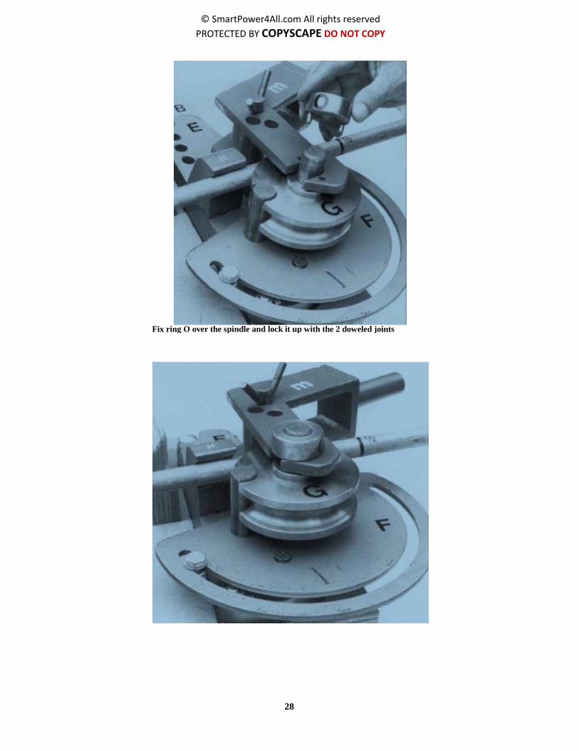
To start bending we use a bending-claw m with accessory cylinder K plus half-shaft. Put cylinder K
half-shaft into the third hole of bending-claw m.
Slip the bending-claw m over the spindle. (disk G and pipe are in between the claw)
28
© SmartPower4All.com All rights reserved
PROTECTED BY COPYSCAPE DO NOT COPY
Fix ring O over the spindle and lock it up with the 2 doweled joints

29
© SmartPower4All.com All rights reserved
PROTECTED BY COPYSCAPE DO NOT COPY
Press pipe-guide P between pipe and cylinder K.
Slip the lever over the handle of bending-claw m and pull the lever towards you.

30
© SmartPower4All.com All rights reserved
PROTECTED BY COPYSCAPE DO NOT COPY
To bend correctly use the following instructions:
- Bend gradually without forcing the set.
- About halfway the bend pipe-guide P must be moved forward.
- Press the lever until the bending-claw runs up against the
adjusting-nut in the groove of bending plate F. If the radius of the bend
looks too wide, the adjusting nut should be moved. The horizontal
pieces of the pipe should be slightly inclined upwards to avoid airlocks.
Pipe and lever are now in parallel position.
WARNING: Be sure that the second mark on the pipe is still corresponding with the mark on the disk
G.
Moving the pipe-guide P

31
© SmartPower4All.com All rights reserved
PROTECTED BY COPYSCAPE DO NOT COPY
adjusting nut
The location of the adjusting nut. Use this nut to set the correct (maximum) bending angle of the pipe.
- After the first bend is completed put a mark at 56 cm distance
from the beginning of the first bend. Here we will start the second
bend.
- For all the next bends the same manner is used. The pictures on
the next page indicate the bending procedure while making the 7
bends.
Use a water pump plier to prevent that the pipe slips away during the bending activity. Keep the pipe
tight just in front of block H.

32
© SmartPower4All.com All rights reserved
PROTECTED BY COPYSCAPE DO NOT COPY

33
© SmartPower4All.com All rights reserved
PROTECTED BY COPYSCAPE DO NOT COPY
Cutting the galvanized sheet
Tools needed:
- a folding ruler
- a marker (felt pen)
- a carpenters square (to mark the right angles)
- a cutting shear or a good tin snips
- a straight lath. (to draw the needed lines on the
sheet)
Out of an available sheet we have to cut the required surface of the absorber. The most favourable thickness is 1 mm, but 0,5 mm can also be used.
Set out the following measurements: - length 110 cm - width 80 cm
Cut out the measured surface with a cutting shear.
Prepare to join the pipe and the sheet
Tools needed:
- a folding ruler or measuring rod
After bending the pipe, it will spring back. To keep the right angle in between the bends, you
have to measure 12 cm. (in the middle)

34
© SmartPower4All.com All rights reserved
PROTECTED BY COPYSCAPE DO NOT COPY
- a felt pen
- the complete bending set - a carpenters square
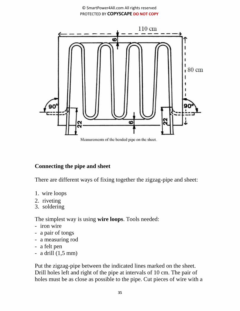
Put a zigzag-pipe on top of a sheet of 110 cm x 80 cm. All bends, both
to the right and to the left must be at an equal distance away from both
ends of the sheet. (about 6 cm).
The distance from both pieces on top and bottom to the edges of the
sheet must be equal as well. (see picture below).
Now mark the contours of the
entire zigzag-pipe on the sheet
with a felt pen. (see picture on the
right).
Put a mark at 22 cm from both
ends of the zigzag-pipe.
Transfer the mark to the sheet. From that marked point we have
to draw a line. Use a carpenter’s
square to draw that line, which
makes a square angle to the edge
of the sheet. (see picture below).
This line indicates the angle to be made by bending both pipe ends.
The angle between pipe end and sheet must be 90°. (see picture below).
Now we use again the bending set. The bending must be carried out
with caution. After bending, put the zigzag-pipe again on the sheet.
Check the angle between pipe-end and sheet by means of a carpenter’s
square. If the angle is not 90°, improve it.
35
© SmartPower4All.com All rights reserved
PROTECTED BY COPYSCAPE DO NOT COPY
Connecting the pipe and sheet
There are different ways of fixing together the zigzag-pipe and sheet:
1. wire loops
2. riveting 3. soldering
The simplest way is using wire loops. Tools needed:
- iron wire
- a pair of tongs
- a measuring rod
- a felt pen
- a drill (1,5 mm)
Put the zigzag-pipe between the indicated lines marked on the sheet. Drill holes left and right of the pipe at intervals of 10 cm. The pair of holes must be as close as possible to the pipe. Cut pieces of wire with a

36
© SmartPower4All.com All rights reserved
PROTECTED BY COPYSCAPE DO NOT COPY
length of 10 cm. Thread a piece of wire trough a pair of holes and
wound it around the pipe until it is firmly fixed to the sheet. Continue the winding until all wire loops are completed. Check that the zigzag- pipe and the sheet are entirely fixed together. Now the absorber is ready to be painted.
Connecting the pipe and sheet by soldering
We will show you the soldering method as well, in case you prefer
doing it this way.
Soldering gives the best heat conduction between pipe and sheet. Tools
needed:
- a soldering lamp (see photo) with fuel (e.g. petrol or kerosene)
- matches and a candle
- sandpaper;
- soldering flux
- soldering tin
Connecting the pipe and sheet with wire loops.

37
© SmartPower4All.com All rights reserved
PROTECTED BY COPYSCAPE DO NOT COPY
- an injection syringe
- a soldering clamp consisting of 2 parts,
a steel triangle and a
wooden support. (see picture)
- a cutting shear
- a hammer
- 1 or 3 screw-drivers
- a bucket filled with cold water
- some cloths
- a measuring rod
- a felt pen
Constructing the wooden support of the soldering clamp
The soldering clamp belongs to the outfit of your tool set. It has a
triangle-form steel body with 2 holes. (One at the base and one at the
top). Through the holes 17 cm long M10 bolts must be sticked. (with
the thread ends at the topside). Onto the thread-ends wing-nuts can be
fastened and unfastened. To use the steel triangle for soldering, a
rectangular-form wooden support has to be made.
For constructing the wooden support, the following tools are
needed:
- a ruler and a marker - a saw
The soldering clamp

38
© SmartPower4All.com All rights reserved
PROTECTED BY COPYSCAPE DO NOT COPY
- a drill
- a chisel
- a carpenter’s square
- a water level
Material needed
- timber of a good quality
The timber must be sawed into 1 block with the following dimensions:
- length 100 cm.
- width 24 cm
- thickness 5 cm
After constructing the wooden block, put the triangle lengthways on
top of the wooden support. Perforate through the holes in the steel
triangle the wooden support. (see picture below)
Now the wooden support can be fixed to the steel triangle by using the
long bolts and wing-nuts.
Preparing the soldering
Put the zigzag-pipe between the indicated lines on the sheet. Mark with
a felt pen the 4 outer bends of the pipe with the numbers 1-2-3-4. Copy
next to the four bends the numbers also on the sheet. (see picture
below).

39
© SmartPower4All.com All rights reserved
PROTECTED BY COPYSCAPE DO NOT COPY
Draw 3 lines from the middle of the 3 inner bends. Cut the sheet along
the 3 drawn lines into 4 stripes. Sand the marked place in between the
indicated lines. (see photo).
Sand it thoroughly with sandpaper without wiping out the contours and
numbers.
Sand also thoroughly the bottom side of the zigzag-pipe (the number of
the 4 bends are at the top (see photo). Then free also the sanded pipe from dust.
Clean it afterwards with some dry cloth
Mark the 4 outer bends of the pipe with the number 1-2-3-4. Copy these numbers to the sheet
next to the numbers
Sand the marked area in between the lines

40
© SmartPower4All.com All rights reserved
PROTECTED BY COPYSCAPE DO NOT COPY
The soldering procedure
The soldering of indicated sheet-strips and corresponding pipe-pieces is done one by one. The sequence is 2-3-4-1. For soldering we need thin and flat strips of tin solder of 10 cm length. Cut available wire tin solder into strips of 10 cm and flatten it with a hammer. If no special soldering flux is available (S.39) pour hydrochloric acid in a glass jar and dissolve some small pieces of zinc in it. After a few days the liquid will get a bluish-green colour. Then it can be used as soldering flux.
For soldering we use a solid table around which you can easily walk.
Put the triangle clamp onto the
table. Unscrew the two wing-
nuts and take off the steel
triangle. Put the sheet strip
with number 2 on the wooden
support and fit the zigzag-pipe
with outer bend 2 on strip 2.
Replace the steel triangle on
the pipe. The bend must
protrude equally to both sides. Turn home firmly the two wing nuts.
Check that pipe and sheet are entirely pressed together. Fill the
soldering lamp with needed fuel and start the preheating procedure.
For different kinds of soldering lamps there are different instructions.
Read these instructions punctually.
While preheating the soldering lamp, light on a candle because during
the start of the burner escaping vapours often extinguish the preheating
flame. As soon as the soldering lamp burns regularly, fill the injection
syringe with soldering flux. Inject the flux evenly between pipe and
sheet. Follow the outer contour of the zigzag-pipe from beginning to
end.
Then squeeze the 10 cm strips of tin-solder between zigzag-pipe and
sheet.

41
© SmartPower4All.com All rights reserved
PROTECTED BY COPYSCAPE DO NOT COPY
The Solar Water Heater
Use a screw-driver to press the strips firmly under the pipe. The tin
strips should curve with the bend and follow the outer contour of the
zigzag-pipe (just in the same places where the soldering flux was
injected).
Take the burning soldering lamp and move it slowly to and for
alongside the triangle. After preheating the triangle point the burner to
the pipe and follow slowly the pipe-sheet connection (never point the
burner directly to the sheet).
If necessary, inject some more soldering flux. Should one of the tin
strips slip out, squeeze it in again with a screw-driver. As soon as the
tin becomes liquefied, follow the flow line along the entire pipe-sheet
connection. After that, stop the soldering procedure immediately. Wait
a moment for the tin solder to solidify. Then cool down the solder joint
of pipe and sheet with damp cloths and next to remove the superfluous
soldering flux.
Unscrew the wing nuts of the triangle. Use safety gloves and take care
for they are hot. Take off the steel triangle and clean the sheet and pipe
once more with a damp cloth. The pipe-sheet connection nr.2 is now
completed.
Put sheet strip nr. 3 on the wooden support and fit the zigzag-pipe with
outer bend nr. 3 on the strip. Repeat now the whole soldering
procedure. That is to say: The Fasten the steel triangle, inject soldering
flux, squeeze in tin solder strips and start soldering. Take care that you
have an exact connection with the adjoining sheet strip. After finishing
pipe-sheet connections nr. 4 and nr. 1 the four strips are soldered
together.
Therefore keep two sheet strips in position with a pair of pliers. Drop a
few drops of soldering flux on the seam of the two connecting sheets.
Heat this spot with the soldering lamp and liquefy a few drops of tin
solder on it. After solidification of the solder cool down the joint with a
damp cloth. Now the soldered absorber is ready to be painted.
See the following pictures
41

42
© SmartPower4All.com All rights reserved
PROTECTED BY COPYSCAPE DO NOT COPY
Press the strips firmly under the pipe
Wait a moment for the tin to solidify
Take the burning soldering lamp and move it
slowly to and for alongside the triangle
Then cool down the solder joint of pipe and sheet
with damp cloths and next to remove the
superfluous soldering flux
Inject the flux evenly between pipe and sheet

43
© SmartPower4All.com All rights reserved
PROTECTED BY COPYSCAPE DO NOT COPY

44
© SmartPower4All.com All rights reserved
PROTECTED BY COPYSCAPE DO NOT COPY
Painting the absorber
Tools needed:
- a tin red lead paint or primer (content 1 litre)
- a tin dull blackboard paint (content 1 litre)
- 1 brushes
- water soap and cloths
Clean the absorber thoroughly with soap suds and then dry it with
cloths. After freeing the absorber of dust, paint the topside (where
zigzag-pipe and sheet are joined together) with red lead. Paint it well
coated but not too thick. Leave the red painted absorber to dry. Finish
the absorber by painting the topside twice with dull blackboard paint.
(see photo) The black painted absorber is now ready to be placed into
a casing.
Collector box
To complete the solar collector we must put the absorber into a
wooden box. (see picture below) The wooden box consists of four
vertical sides a-b-c-d and bottom e. Inside the box supporting laths F
are fastened to a-b and c. (see picture below). The absorber is placed

45
© SmartPower4All.com All rights reserved
PROTECTED BY COPYSCAPE DO NOT COPY
on these supporting laths. The box is covered with a glass sheet.
Tools needed:
- a hammer
- a saw
- a pair of tongs
- a plane
- a rabbet-plane
- a chisel
- a drill
- a carpenters square
- a waterlevel
- files (round and flat)
- screw-drivers
- screws and nails
- a mitre box
- a folding ruler
- a marker (pencil or felt pen)
- a glass-cutter
- a straight lath (to draw straight lines)

46
© SmartPower4All.com All rights reserved
PROTECTED BY COPYSCAPE DO NOT COPY
The Solar Water Heater
Materials needed:
- timber of good quality divided into the following parts and
dimensions
- 2 planks for sides a and d: length 90 cm, width 10 cm, thickness 3
cm
- 2 planks for sides b and c: length 120 cm, width 10 cm, thickness 3
cm
- 3 supporting laths: length 120 cm, width 2.5 cm, thickness 2.5 cm
- planks for the bottom: depending on available sizes, thickness 2.5
cm
- insulating material (kapok, sawdust, coconut fibre, etc., enveloped
in bags)
- rubber strips (made out of old inner-tires of cars)
- glass to cover the box (thickness about 5 mm.)
- silicone-kit or putty
- galvanised sheet with a thickness of 0.5 to 1 mm (for making angle-
sections)
Before you start to make the box, pay attention to the following points:
- The size of the absorber determines the internal dimension of the
collector-case.
- When an absorber has the following measurements: length 110 cm.,
width 80 cm, the internal dimension of the case must be 111 cm
(length) and 81 cm (width). It means that a space of half a cm must be
all around the absorber.
- The depth of the collector-case must be 10 to 15 cm. Halfway the
depth, which means at 5 to 7.5 cm, supporting laths must be fastened
on which the absorber is placed.
45

47
© SmartPower4All.com All rights reserved
PROTECTED BY COPYSCAPE DO NOT COPY
Now we can start the following activities: (see picture)
- Saw to size the four sides of the box (a-b-c-d).
- Cut a rebate of 1.5 cm wide and 1 cm deep in the top of sides a-b-c.
Make the topside of d level to the rebates of a-b-c. (see picture).
- Put a mark halfway the depth of a-b-c and draw a line along the
marks.
- Saw the supporting laths for sides a-b-c. The supporting laths must
be placed along the marked line. The topside of the supporting laths
must
touch the
lines. (see
picture).
- Fasten
the
supporting laths to sides a-b-c.
- To test the dimensions of the box, put sides a-b- c together and place
the absorber onto the supporting laths.
- Mark the point of the pipe-outlet on side a.
- Bore a hole on the
marked point and stick out
the pipe through side a.

48
© SmartPower4All.com All rights reserved
PROTECTED BY COPYSCAPE DO NOT COPY
- Place side d towards the absorber and mark the point of the pipe-
inlet on d.
- Make a hole in side d. Now you can move side d towards sides a-b-c
while the pipe-inlet and outlet stick out of the box.

49
© SmartPower4All.com All rights reserved
PROTECTED BY COPYSCAPE DO NOT COPY
- Test the internal dimension of the box. That means look if there is
enough space all around the absorber.
- Move away side d and take out the absorber. Side d will remain
open until the absorber can be placed definitively into the box.
Insulation layer
The insulation layer must be placed at the bottom of the collector-box.
Tools needed:
- a sewing machine
- sewing-thread
- a pair of scissors
- a strong needle
- a ruler
- a pencil or felt pen Materials needed:
- empty bags of jute or fibre
- kapok, saw-dust, coconut-fibre, glass-wool or any kind of other
insulating material
Measure the total surface of the bottom of the box. Measure also the
thickness of the insulation layer. (the layer must fill-up the space
between the bottom of the collector box and the top of the supporting
laths).
wooden box

50
© SmartPower4All.com All rights reserved
PROTECTED BY COPYSCAPE DO NOT COPY
Make an empty envelope out of the bags, which can fill-up the
indicated space. It is advisable to sew 4 or 5 parallel running empty
tracks into the envelope to be filled-up with insulation material. Now
we put the filled envelope onto the bottom of the box. Check that the
thickness of the insulation layer is equal all over the bottom (and does
not reach too much above the supporting laths).
Place the absorber onto the supporting laths. The absorber covers the
insulation layer at the bottom of the box. Now replace side d and join
the four sides A-B-C-D firmly together. Use screws, nails or wooden
pins.
Glass cover
Tools needed:
- a glass-cutter
- a folding ruler
- a straight metal lath
- a felt pen
- a carpenters square
- a level table useful to cut the glass-
sheet
- a blanket to cover the table
- a pair of scissors
- a cutting shear
- a drill
- a screw-driver
Make sure the width of the glass sheet is at both sides 2
mm shorter than themeasured distance.

51
© SmartPower4All.com All rights reserved
PROTECTED BY COPYSCAPE DO NOT COPY
The Solar Water Heater
Materials needed:
- a glass-plate of about 4 mm thickness and a surface of at
least 125 x 90 cm
- an old inner-tire of a motorcar
- silicone-kit or putty
- a galvanised sheet with a thickness of 0.5 mm
- small screws and nails
Now you can estimate exactly the needed surface of the glass-sheet to
cover the collector-box. Clean the available glass-plate (125 x 90 cm.)
with a wrap. Put the available glass-plate onto the table, covered with a
blanket.
Draw the measured length and width onto the available glass-plate.
Use a carpenter square. Put the metal lath along the drawled lines on
the available glass-plate. Strike with the glass-cutter the exact length
and width of the needed glass-sheet. By using the glass-cutter carve
the needed glass-sheet out of the available glass-plate.
Now you have the needed surface of the glass-sheet to cover the box.
Before placing the glass-sheet onto the box start making rubber strips
out of the inner-tire. Measure the width of the rebates of sides A-B-C
and also the total width of side D. Cut out small rubber strips from the
inner-tire. The rubber strips must cover the width of the rebates of sides
A-B-C as well as the total width of side D. Fasten with small nails these
strips onto the rebates of A-B-C and onto side D.
Start to measure the exact width between the rebates of sides B and C.
(see picture above). Use a carpenters square. The width of glass-sheet
must be about 2 mm smaller at both sides. The length of the glass-
sheet must reach from the rebate on top of the box to about 2 cm over
the width of side D.
49

52
© SmartPower4All.com All rights reserved
PROTECTED BY COPYSCAPE DO NOT COPY
Cut out also 2 rubber discs with a diameter of 8 cm. Make a small hole
in the middle of the discs. Slip the discs over the in- and outlet pipes of
the absorber. Nail the discs to the collector-box.
angle selection
silicone kit wooden box
Fasten rubber strips over the rebates of sides A-B-C and D
glass sheet
side A
rubber strip absorber
rubber strip
insulation layer
side D

53
© SmartPower4All.com All rights reserved
PROTECTED BY COPYSCAPE DO NOT COPY
Now you can place the glass-sheet onto the rubber strips. (see picture
above) To finish the covering of the collector-box, make angle sections
out of galvanised sheet. (see also picture above). The angle sections
must cover the total length of sides B and C and the width of side a.
The sections must be fastened by small screws. Fill-up the space
between angles and glass-sheet with silicone-kit or putty.
Finally seal all corner joints of the collector-box with putty and paint
the box completely outside.
The storage tank
For the storage tank we use a 200-litre drum. It should be a closed one
in which no chemical or other dangerous fluids have been stored. Oil,
diesel, petrol and soap drums are usable provided they can be cleaned
with hot water and soda. To the storage tank there are 5 pipe-
connections to be joined. And afterwards the tank must be insulated
very well.
Fill-up the space between angles and glass-sheet with silicone-kit or putty

54
© SmartPower4All.com All rights reserved
PROTECTED BY COPYSCAPE DO NOT COPY
Tools needed:
- a folding ruler
- a marker
- a centre point
- a drill (6 mm and 16 mm)
- a hammer
- a round file
- a steel cone
- a hack-saw or pipe cutter
- a thread-cutter. (^” and %”)
- a carpenters square
- a piece of sandpaper
- a soldering lamp
Materials are needed:
- a 200 litre (second hand but in good condition)
- a i4” galvanised pipe with a length of 1 meter
- a %” galvanised pipe with a length of 60 cm

55
© SmartPower4All.com All rights reserved
PROTECTED BY COPYSCAPE DO NOT COPY
- soldering flux and thin
Start to saw 4 pieces of 14-inch pipe. Each with a length of 15 cm.
Make thread at one side of each piece and clean the other side with
sand-paper. These 4 pieces have to be fitted into the drum. 2 pieces
will be used for the connections between storage tank and collectors, 1
for the cold water inlet and 1 for the hot water outlet. Saw another
piece of % inch with a length of 30 cm. Make thread at both sides.
This piece of pipe is fitted into the % bunghole at the top of the drum.
This is the vent.
The soldering procedure
Right down of the vent we mark 2 spots onto the drum, 1 at 35 cm
from the top and 1 at 10 cm from the bottom of the drum. Strike both
sides spots with a centre-point. Then drill first a hole of 6 mm and
afterwards a hole of 16 mm into the same spot.
Locations of the connections between storage tank and collectors

56
© SmartPower4All.com All rights reserved
PROTECTED BY COPYSCAPE DO NOT COPY
Put the drum horizontal and debur one hole with a round file. Widen
that hole by using a steel cone and a hammer until the pipe fits exactly.
Finally, clean the hole and start solderin. Do the same worth the other
pipe-pieces. Squared to the collector-connections fit the hot water
outlet at 25 cm from the top of the drum. Just opposite the hot water
outlet fit the cold water inlet at 10 cm from the bottom of the drum.
First, drill a hole of 6 mm and afterwards a
hole of 16 mm into the marked spots
Debur the holes with a round file until the
holes have diameter of 18 mm
By using the steel cone and hammer widen The thread-end of the pipe must be
kept outside of the
one hole until a W piece of pipe fits in drum. All pipes stand
perpendicular of the drum

57
© SmartPower4All.com All rights reserved
PROTECTED BY COPYSCAPE DO NOT COPY
Thoroughly clean the pipe and driven-in Then solder the piece of pipe in upright position
hole with sand-paper securely into the hole
The insulation of the storage tank
To preserve the water temperature inside the storage tank, we have to
insulate it. Therefore an insulating layer of at least 5 cm thickness all
around and on top of the storage tank is necessary. For insulating we
can use different kinds of materials such as: kapok, coconut, fibre,
sawdust, and any other available insulating material.
The insulating material must be locked into a cover. Empty sacks can
be used but it seems better to make suitable covers by yourself. The
self-made covers must have a length of 90 cm. (corresponding the
height of the drum). Divide the covers in parallel running casings. The
total width of the self-made covers must easily surround the
circumference of the drum. Take care that the soldered pieces of pipe
stick out.
After surrounding the storage tank with insulating covers, entwine
them with ropes or iron wire. To insulate the top of the storage tank,
use a self-made pillow. To protect the insulation layer against rain and
dust, make a metal envelope out of a galvanised corrugated or flat-
plate sheet. On top of the metal envelope you can make a cap. Take
care that all pieces of pipe stick out of the metal envelope. To fasten
the metal envelope use iron wire, screws or riveted joints.

58
© SmartPower4All.com All rights reserved
PROTECTED BY COPYSCAPE DO NOT COPY
The metal envelope and the cap
Around the insulation layer of the storage tank we make a metal
envelope. Corrugated or flat galvanised sheets are useful. The length of
envelope is about 95 cm. The circumference depends on the thickness
of the insulation layer (usually 2 or 3 pieces are necessary). Start to
place the insulated storage tank on a wooden disk (diameter 70 cm).
Fold the envelope-pieces around and measure the spots where pipe-
pieces stick out.
Make holes at the indicated spots. Fold the envelope-pieces again and
entwine them with ropes or iron wire.
Fix the envelope with nails to the wooden disk. Finally, fix the pieces
of the envelope together by entwining it with iron wire.
After insulating the top of the storage tank with a self-made pillow, we
start to make a metal cap. Use a flat plate disk with a diameter of 100
cm. Make a gash to the centralpoint of the disk. By sliding you can
make a cap-model. Measure the spot where the vent sticks out.
The total width of the self-made covers must easily surround the circumference of the drum

59
© SmartPower4All.com All rights reserved
PROTECTED BY COPYSCAPE DO NOT COPY
Make a hole at the indicated spot. Finally, fix the cap onto the top of the
metal envelope. (see photo)
The buffer tank
To replenish the storage tank we use a buffer tank. The buffer tank is
connected to an existing water supply system. Therefore the buffer
tank is provided with a floating gauge. Via a flexible hose the buffer
tank is connected to the storage tank. For safety an overflow protects
the buffer tank from derangement.
A buffer tank can be made of a washing tub, a plastic tub or a half 200-
litre drum. When using a metal body like washing tub or half drum,
solder a piece of V2” pipe into the buffer tank to connect it with the
storage tank. To finish the buffer tank, make a cover to close the open
side on top.
The buffer tank should be placed higher than the storage tank. This
makes sure that the storage tank is always full with water. Otherwise,
air can get into the storage tank, which caused corrosion. When a
plastic buffer tank is used, it is not necessary to construct a separate
It is easier to work up a flatplate cover around
the storage tank than to use a corrugated one

60
© SmartPower4All.com All rights reserved
PROTECTED BY COPYSCAPE DO NOT COPY
buffer tank. The floating gauge can then be placed inside the plastic buffer tank.
floating gauge
blitter tank
connection to the
storage tank
1. Solar Collectors
2. Storage Tank
3. Upper connection from collectors to storage tank (hot water)
4. Lower connection from storage tank to collectors (cold water)
5. Buffer Tank to refill storage tank
6. Vent
overflow
rater supply system
The buffer tank
Complete solar water system

61
© SmartPower4All.com All rights reserved
PROTECTED BY COPYSCAPE DO NOT COPY
The installation of the Solar
Water Heater
Foundation
For the construction of the
foundations various kinds of
materials can be used. It is obvious
that stones, blocks and bricks are
convenient construction materials.
They can usually be made on the
spot.
For example we will describe a construction composed of walls built of
bricks with unequal height to support the collectors. 1+2 pedestal as a
supporting point for the insulated storage tank and buffer tank 3.
Tools needed:
- a complete outfit for masonry (among others trowels) - a water level - a folding ruler
Materials needed:
- bricks
- cement
- sand
For an exact design and all needed measurements to build up these
foundations see the following sketches.
As you can see the pedestal for the storage tank is 50 cm higher than
the second (highest) wall on which the collectors are placed. This
provision is necessary to secure that the natural circulation of the hot

62
© SmartPower4All.com All rights reserved
PROTECTED BY COPYSCAPE DO NOT COPY
water system comes into being. All details about the construction are
described below.
Numbers 1-2-3 in the pictures are foundations.
A = water supply system (to buffer tank)
B = refilling pipe (buffer to storage tank)
C = lower connection (to collectors)
D = upper connection (to storage tank)
E = hot water outlet to tap
After the foundations are completed you can start to install the
collectors, the storage tank and the buffer
tank.
For installation of the hot water system, the following tools are needed:
- a pipe-cutter or hack-saw
- a pipe holding clamp. (fasten on a solid bench)
- a screw thread cutter
- spanners and adjustable wrenches
- water pump pliers
- a water level
- a folding ruler;
- a marker
- screw-drivers
Make sure that the top of the storage tank is at the same level as the bottom of the buffer tank. This ensures
that the storage tank is always completely filled with water, which prevents the storage tank from corroding

63
© SmartPower4All.com All rights reserved
PROTECTED BY COPYSCAPE DO NOT COPY
The following materials are needed:
- 2 or 3 14" galvanised water supply pipes (*)
- 8 galvanised 1/2" elbows
- 6 same 4" sockets
- 6 same 4" T -pieces
- 3 same 4" plugs
- 3 same 4" caps
- 2 same %" to 4” reducing sockets (*)
- 3 same 4" unions (*)
- 2 same 4" stop rocks
- 2 same 4" taps
- 5 meter heat-resistant flexible hose. (inner diameter 18 mm.)
- 30 hose clips
- depending on which materials are locally available and how to make the joints with the existing water
supply system
Placing the collectors
We start to place the collectors onto the foundation walls. It is
advisable to rinse them before placing, because inside the zigzag-pipes
dirt and vermin may have been collected. For example, we describe the
formation of 3 collectors set up in parallel position.
(*)

64
© SmartPower4All.com All rights reserved
PROTECTED BY COPYSCAPE DO NOT COPY
As you can see (in the picture on the previous page) there are 3
collector inlets at the bottom-side and also 3 collector outlets at the
topside. At the bottom side, an elbow, 2 T-pieces and a tap are fit to the
inlets. By opening the tap it is possible to drain the whole system when
necessary. Draining the system is necessary for example when too
much dust has been collected in the collector-pipes; this hinders the
flow of water through the system.
At the top side of the collectors, connect an elbow on the left
connection, and two T-pieces to the other two connections as indicated
in the picture on the previous page.
/4" pipes with a length of 30 cm each are used to connect the
collectors. (see picture above) Each piece of pipe has thread at both
sides. Screw the 8 pieces of pipe into the T-pieces.
The inlets and outlets are now faced horizontally towards each other.
The space in between the horizontal pipes must be filled up with pieces
of flexible hose. To obtain the natural circulation, the interconnected
outlets must slope upwards. Therefore a difference in height of 1 to 2
cm between the collectors is required.
65
© SmartPower4All.com All rights reserved
PROTECTED BY COPYSCAPE DO NOT COPY
The pieces of flexible hose must be attached to the pipes by hose clips.
Placing the storage tank
After the interconnection of the 3 collectors is completed, we start to
install the storage and buffer tank. It is advisable to support both tanks
with planks before putting them onto the foundation. The surface of the
supporting planks corresponds with the diameter of the tanks. Face the
storage tank towards the collectors with the 2 pipes that are destined
for it.
Now start to connect the existing water supply to the floating gauge in
the buffer tank. The buffer tank must be placed with the inlet backwards. Install a 14" stop cock between water supply and buffer tank. The stop cock should remain closed until the whole installation is finished.
Make the connections between buffer tank and storage tank, the
connections between storage tank and inlet at the bottom of the
collectors and the connections between the outlet of the collectors and
the storage tank.
ATTENTION
The connection between the outlet of the collectors and the storage
tank must continuously slope upwards. Otherwise the natural
circulation does not come into being. The last connection to be made is
the hot water outlet from storage tank to tap. All connections are partly
made by 4" pipes and pieces of flexible hose.
Testing the hot water system
When the hot water system has been installed we start to test the
system. Open the stop cock on the water supply pipe. Also open the hot
water tap. Cold water starts entering via the floating gauge into the
buffer tank and from there via the connection into the storage tank.
From the storage tank the water flows via the lower connection to the
inlets at the bottom of the 3 collectors. As soon as the collectors are

66
© SmartPower4All.com All rights reserved
PROTECTED BY COPYSCAPE DO NOT COPY
filled-up with cold water, the solar radiation starts heating up the water
inside the collectors. The heated water will start rising up to the storage
tank via the upper connection. During the hot water flow from the
collectors to the storage tank, air-bubbles and possibly steam will
escape via the vent on top of the storage tank.
When the whole storage tank is almost filled up, hot water will flow
out of the warm water tap. (maybe it starts with some escaping air-
bubbles). Now close the tap and check all connections of the system.
When the whole system functions without leaking, you can start the
insulation of the hot water system.
The insulation of pipe connections
Without proper insulation of the pipe connections between collectors
and storage tank a large part of the output of the hot water system will
get lost. The hot water outlet from storage tank to the tap must be
insulated as well. Pipe insulation has to be renewed from time to time.
For insulating the pipe connections various materials can be used. Pay
attention that the outside of the insulation must be water-repellent.
Some example insulation materials:
- Woollen cloths cut into strips and winded around the pipes, for this
use plastic also cut into strips has to be winded round the woollen
cloths.
- Bracts of banana trees are also useful because they are water
repellent by themselves. After wetting the banana bracts, you can wind
them easily around the pipes. To finish it tie them up with their own
grain.
- Many other materials can be used for insulation. It depends on what
is locally available.
While insulating the pipe connections keep attention to the basic principle:

67
© SmartPower4All.com All rights reserved
PROTECTED BY COPYSCAPE DO NOT COPY
ALL CONNECTIONS FROM COLLECTORS TO STORAGE
TANK MUST SLOPE UPWARDS
Other collector set-ups
Besides the given example of a system with 3 parallel connected
collectors, there are other ways to connect the collectors. For example
connection in series. (see picture). To do this, make a set-up of 2 or 4
collectors.
As you see, the collector in-and-outlets are directed towards each other.
On both the collector outlets at the top 2 elbows of 90 degrees are
placed and directed to the centre. In the centre itself a T-piece or twin
elbow is placed. At the bottom, the collectors are connected in the
same way. To improve the outcome of a system it is possible to install
a set-up of 4 collectors that are connected 2 by 2 in series.
The advantage of such set-ups is that it is of lesser importance that the
collectors need to be placed in such a way that the water flow remains
up-going.
Connecting the collectors in series
Twin elbow

68
© SmartPower4All.com All rights reserved
PROTECTED BY COPYSCAPE DO NOT COPY
Maintenance
To keep a hot water system in good condition it is necessary to
maintain it regularly. There are 2 possible things interrupting the
operation of the system; enclosed air and dust.
Checking enclosed air in the system
The natural circulation of the water in the system only works when
there is no air enclosed in the system. There are two possible causes for
enclosed air; the air vent is choked or not all the connections slope
upwards.
When hot water circulation starts inside the collectors, small air
bubbles will join the circulation. These air bubbles start rising up to the
top of the storage tank and leave it via the vent (air-outlet). So it is
necessary to check the vent to see that it is not choke.
To maintain the hot water circulation of a system all connections must
slope upwards.
Here you see a connection from collector
running up tostorage tank. Because there is a
dip in that connectionan air bubble will block
the circulation immediately and consequently
the system stops functioning
This connection is sloping upwards and so there are
no problems with the hot water circulation

69
© SmartPower4All.com All rights reserved
PROTECTED BY COPYSCAPE DO NOT COPY
Checking dust
At the lowest point of the collectors (the lowest point of the system) a
tap or movable plug has to be installed (a vertical T-piece). If there are
problems with the hot water circulation (not because of air) you have
to open the tap. This will cause the dirt to flow out of the system.
dust
Dust in the lowest point of the system may prevent the water flow
Dust clouds falling down upon the glass cover of the collectors will
dim the radiation of the sun. So clean the glass covers from time to
time.
The second bend of this
collector is pointed down. Air
bubbles will not pass it. So the
circulation will be blocked
This collector is well bend
because all bends are sloping
upwards. So the hot water
circulation continues without
any problem

70
© SmartPower4All.com All rights reserved
PROTECTED BY COPYSCAPE DO NOT COPY
Conclusion
Congratulations! You have built your own Solar Water Heater! We
hope you enjoyed it and are ready to benefit from it.
It is a fact: a solar hot water system is not just a conscientious purchase
for the environment, it has real and practical benefits for you the
consumer/homeowner. Studies over the years have shown that
homeowners and businesses who have installed solar hot water systems
have been delighted with their advantages.
Independence is a notion that is starting to win ground. We can
contribute to this grand ideal through the conservation of energy. As
fuel prices increase, it is easy to see the effects of our dependence on
foreign energy sources. It is a matter of time before everyone realizes
that the sun is our saviour.
It’s time to go solar!


