
THE ULTIMATEMEMORY GUIDE
Everything You Ever Wanted to Know About Memory
C O M P U T I N G W I T H O U T L I M I T S®
®
w w w . k i n g s t o n . c o m

THE ULTIMATE MEMORY GUIDE KINGSTON TECHNOLOGY

©2000 Kingston Technology
Company, Inc. All rights reserved.
All trademarks and registered
trademarks are the property of
their respective owners.
PowerPC is a trademark of
International Business Machines
Corporation, used under
license therefrom.Windows
is a trademark of Microsoft
Corporation. All other
trademarks and registered
trademarks are the property
of their respective owners.
This publication may contain
typographical errors or
technical inaccuracies.
Any errors will be periodically
corrected in future updates
of this publication. Kingston
Technology reserves the right
to make changes to text and/
or illustrations in this document
at any time.
This publication is the sole
property of Kingston Technology
and may not be copied or
modified in part or in whole
without the express permission
of Kingston Technology.

3
THE ULTIMATE MEMORY GUIDE KINGSTON TECHNOLOGYCONTENTS
WHAT IS MEMORY?
INTRODUCTION
THE ROLE OF MEMORY IN THE COMPUTER
THE DIFFERENCE BETWEEN MEMORY AND STORAGE
MEMORY AND PERFORMANCE
HOW MUCH MEMORY DO YOU NEED?
A CLOSER LOOK
WHAT MEMORY LOOKS LIKE
WHERE MEMORY COMES FROM
WHERE MEMORY GOES IN THE COMPUTER
HOW MEMORY WORKS
HOW MEMORY WORKS WITH THE PROCESSOR
MAXIMIZING PERFORMANCE
HOW MUCH MEMORY IS ON A MODULE?
BITS AND BYTES
CPU AND MEMORY REQUIREMENTS
CALCULATING THE CAPACITY OF A MODULE
STACKING
DIFFERENT KINDS OF MEMORY
MODULE FORM FACTORS
MAJOR CHIP TECHNOLOGIES
MEMORY TECHNOLOGIES FOR VIDEO OR GRAPHICS PROCESSING
OTHER MEMORY TECHNOLOGIES YOU MAY HAVE HEARD ABOUT
ERROR CHECKING
OTHER SPECIFICATIONS
5
19
29
39
49

WHAT TO CONSIDER WHEN BUYING MEMORY
COMPATIBILITY
HOW TO READ A BANK SCHEMA
QUALITY
PRICING AND AVAILABILITY
HOW TO INSTALL MEMORY
BEFORE YOU INSTALL
IMPORTANT THINGS TO KEEP IN MIND
INSTALLING THE MEMORY
TROUBLESHOOTING MEMORY PROBLEMS
COMMON MEMORY PROBLEMS
BASIC TROUBLESHOOTING
WHEN THE PROBLEM OCCURS
HANDLING SPECIFIC PROBLEMS
STILL NEED HELP?
MORE ABOUT KINGSTON
COMPANY OVERVIEW
HOW TO REACH KINGSTON
WHY KINGSTON?
THE GLOSSARY
THE ULTIMATE MEMORY GUIDE KINGSTON TECHNOLOGYCONTENTS
71
83
93
103
111

WHAT IS MEMORY?
INTRODUCTION
THE ROLE OF MEMORY IN THE COMPUTER
THE DIFFERENCE BETWEEN MEMORY AND STORAGE
MEMORY AND PERFORMANCE
HOW MUCH MEMORY DO YOU NEED?

7
THE ULTIMATE MEMORY GUIDE KINGSTON TECHNOLOGYWHAT IS MEMORY?
INTRODUCTION
These days, no matter how much memory your computer has, it never seems to bequite enough. Not long ago, it was unheard of for a PC (Personal Computer), tohave more than 1 or 2 MB (Megabytes) of memory. Today, most systems require64MB to run basic applications. And up to 256MB or more is needed for optimalperformance when using graphical and multimedia programs.
As an indication of how much things have changed over the past two decades, consider this: in 1981, referring to computer memory, Bill Gates said, “640K(roughly 1/2 of a megabyte) ought to be enough for anybody.”
For some, the memory equation is simple: more is good; less is bad. However, forthose who want to know more, this reference guide contains answers to the mostcommon questions, plus much, much more.
THE ROLE OF MEMORY IN THE COMPUTER
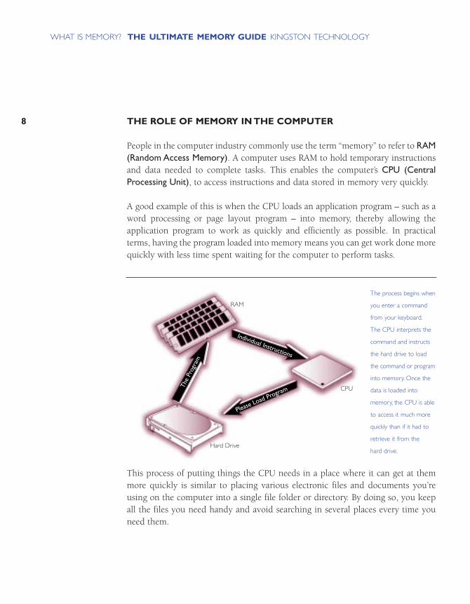
People in the computer industry commonly use the term “memory” to refer to RAM(Random Access Memory). A computer uses RAM to hold temporary instructionsand data needed to complete tasks. This enables the computer’s CPU (CentralProcessing Unit), to access instructions and data stored in memory very quickly.
A good example of this is when the CPU loads an application program – such as aword processing or page layout program – into memory, thereby allowing the application program to work as quickly and efficiently as possible. In practicalterms, having the program loaded into memory means you can get work done morequickly with less time spent waiting for the computer to perform tasks.
This process of putting things the CPU needs in a place where it can get at themmore quickly is similar to placing various electronic files and documents you’reusing on the computer into a single file folder or directory. By doing so, you keepall the files you need handy and avoid searching in several places every time youneed them.
8
THE ULTIMATE MEMORY GUIDE KINGSTON TECHNOLOGYWHAT IS MEMORY?
Hard Drive
RAM
CPU
The process begins when
you enter a command
from your keyboard.
The CPU interprets the
command and instructs
the hard drive to load
the command or program
into memory. Once the
data is loaded into
memory, the CPU is able
to access it much more
quickly than if it had to
retrieve it from the
hard drive.
Individual Instructions
The
Prog
ram
Please Load Program

9
THE ULTIMATE MEMORY GUIDE KINGSTON TECHNOLOGYWHAT IS MEMORY?
THE DIFFERENCE BETWEEN MEMORY AND STORAGE
People often confuse the terms memory and storage, especially when describing theamount they have of each. The term memory refers to the amount of RAM installedin the computer, whereas the term storage refers to the capacity of the computer’shard disk. To clarify this common mix-up, it helps to compare your computer toan office that contains a desk and a file cabinet.
Consider the desk-and-file-cabinet metaphor for a moment. Imagine what it wouldbe like if every time you wanted to look at a document or folder you had to retrieveit from the file drawer. It would slow you down tremendously, not to mention driveyou crazy. With adequate desk space – our metaphor for memory – you can lay outthe documents in use and retrieve information from them immediately, often withjust a glance.
Here’s another important difference between memory and storage: the informationstored on a hard disk remains intact even when the computer is turned off.However, any data held in memory is lost when the computer is turned off. In ourdesk space metaphor, it’s as though any files left on the desk at closing time will bethrown away.
The file cabinet represents
the computer’s hard disk,
which provides storage for
all the files and information
you need in your office.
When you come in to
work, you take out the
files you need from storage
and put them on your
desk for easy access while
you work on them.
The desk is like memory
in the computer: it holds
the information and data
you need to have handy
while you’re working.
MEMORY AND PERFORMANCE
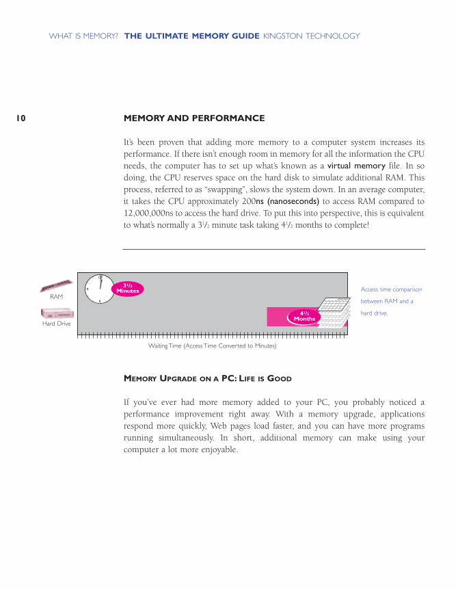
It’s been proven that adding more memory to a computer system increases its performance. If there isn’t enough room in memory for all the information the CPUneeds, the computer has to set up what’s known as a virtual memory file. In sodoing, the CPU reserves space on the hard disk to simulate additional RAM. Thisprocess, referred to as “swapping”, slows the system down. In an average computer,it takes the CPU approximately 200ns (nanoseconds) to access RAM compared to12,000,000ns to access the hard drive. To put this into perspective, this is equivalentto what’s normally a 31/2 minute task taking 41/2 months to complete!
MEMORY UPGRADE ON A PC: LIFE IS GOOD
If you’ve ever had more memory added to your PC, you probably noticed a performance improvement right away. With a memory upgrade, applicationsrespond more quickly, Web pages load faster, and you can have more programsrunning simultaneously. In short, additional memory can make using your computer a lot more enjoyable.
10
THE ULTIMATE MEMORY GUIDE KINGSTON TECHNOLOGYWHAT IS MEMORY?
WAITING TIME (Access Time Converted to Minutes)
Hard Drive
RAM6
9 3
12
JANUARY
JANUARY
JANUARY
JANUARY
JANUARY
31/2Minutes
41/2Months
Access time comparison
between RAM and a
hard drive.
RAM
Hard Drive
Waiting Time (Access Time Converted to Minutes)

11
THE ULTIMATE MEMORY GUIDE KINGSTON TECHNOLOGYWHAT IS MEMORY?
MEMORY UPGRADE ON A SERVER: LIFE IS EVEN BETTER
These days, more and more people are using computers in a workgroup and sharinginformation over a network. The computers that help distribute information topeople on a network are called servers. And their performance has a huge impacton the performance of the network: if a server is performing poorly, everyone onthe network “feels the pain.” So, while a memory upgrade on an individual PCmakes a big difference for the person who uses it, a memory upgrade in a serverhas even more far-reaching effects and benefits everyone who accesses the server.
To better understand the benefits of increasing memory on a server, take a look at theseresults from an independent study done on Windows® NT-based servers.
Number of Clients (Systems)1 4 8 12 16 20 24 28 32 36 40 44 48 52 56 60 64 68 72
Tra
nsac
tions
Per
Sec
ond
300
250
200
150
100
50
0
128MBRAM
256MBRAM
512MBRAM
64MBRAM
Application servers are
utilized to host a wide
range of applications,
such as word processing
and spreadsheet programs.
By increasing base
memory from 64MB to
256MB,Windows NT
Server was able to support
five times as many clients
before transactions per
second dropped.Number of Clients (Systems)
Tran
sact
ions
Per
Sec
ond
12
THE ULTIMATE MEMORY GUIDE KINGSTON TECHNOLOGYWHAT IS MEMORY?
2001 CPU/256MB
0ms
300 100
2001 CPU/512MB
0ms
300 100
59%Time Cut
2001 CPU/64MB
0ms
300 100
2001 CPU/128MB
0ms
300 100
85%Time Cut
Increase Memory from 64MB to 128MB
Increase Memory from 256MB to 512MB
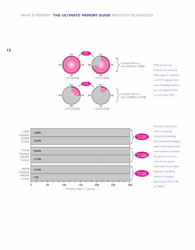
Web servers are
employed to serve up
Web pages in response
to HTTP requests from
users. Doubling memory
can cut response time
by more than 50%.
256MB
512MB
1GB
512MB
256MB
128MB
Directory Mark 1.1 ops/sec0 100 150 25050 200 300
110MB Database(50,000 Entries)
375MB Database(200,000
Entries)
690MB Database(400,000
Entries)
Increase of 947%
Increase of 3000%
Increase of 248%
Directory servers are
vital to corporate
productivity, handling
most email and messaging
tasks. In this environment,
more memory increases
the speed with which
a server can access
information from linked
databases. Doubling
memory increased
performance from 248
to 3000%.Directory Mark 1.1 ops/sec
110MBDatabase
(50,000Entries)
690MBDatabase(400,000Entries)
375MBDatabase(200,000Entries)
1 CPU/64MB
1 CPU/256MB
1 CPU/128MB
1 CPU/512MB
Increase Memoryfrom 64MB to 128MB
Increase Memoryfrom 256MB to 512MB

13
THE ULTIMATE MEMORY GUIDE KINGSTON TECHNOLOGYWHAT IS MEMORY?
HOW MUCH MEMORY DO YOU NEED?
Perhaps you already know what it’s like to work on a computer that doesn’t havequite enough memory. You can hear the hard drive operating more frequently andthe “hour glass” or “wrist watch” cursor symbol appears on the screen for longer periods of time. Things can run more slowly at times, memory errors can occurmore frequently, and sometimes you can’t launch an application or a file withoutfirst closing or quitting another.
So, how do you determine if you have enough memory, or if you would benefitfrom more? And if you do need more, how much more? The fact is, the rightamount of memory depends on the type of system you have, the type of workyou’re doing, and the software applications you’re using. Because the right amountof memory is likely to be different for a desktop computer than for a server, we’vedivided this section into two parts – one for each type of system.
MEMORY REQUIREMENTS FOR A DESKTOP COMPUTER
If you’re using a desktop computer, memory requirements depend on the computer’soperating system and the application software you’re using. Today’s word processingand spreadsheet applications require as little as 32MB of memory to run. However,software and operating system developers continue to extend the capabilities of theirproducts, which usually means greater memory requirements. Today, developers typically assume a minimum memory configuration of 64MB. Systems used forgraphic arts, publishing, and multimedia call for at least 128MB of memory and it’scommon for such systems to require 256MB or more for best performance.
The chart on the next page provides basic guidelines to help you decide how muchmemory is optimal for your desktop computer. The chart is divided by operatingsystem and by different kinds of work. Find the operating system you’re using onyour computer, then look for the descriptions of work that most closely match thekind of work you do.

WIN
DO
WS
®20
00 P
RO
FE
SS
ION
AL
Win
dow
s 20
00 P
rofe
ssio
nal r
uns
soft
war
e ap
plic
atio
ns fa
ster
.Not
eboo
k-re
ady
and
desi
gned
with
the
futu
re in
min
d,W
indo
ws
2000
Prof
essi
onal
allo
ws
user
s to
tak
e ad
vant
age
of
a fu
ll-ra
nge
of fe
atur
es t
oday
.Win
dow
s 20
00Pr
ofes
sion
al is
futu
re-r
eady
and
pro
mis
es t
o ru
nto
day’s
and
tom
orro
w’s
appl
icat
ions
bet
ter.
Base
line:
64M
B –
128M
BO
ptim
al:1
28M
B –
512M
B
Ligh
t-
Wor
d pr
oces
sing
,em
ail,
data
-ent
ry
Med
ium
- Fa
x/c
omm
unic
atio
ns,d
atab
ase
adm
inis
trat
ion,
spre
adsh
eets
;>2
appl
icat
ions
ope
n at
a t
ime
Hea
vy-
Com
plex
doc
umen
ts,a
ccou
ntin
g,bu
sine
ss g
raph
ics,
pres
enta
tion
soft
war
e,ne
twor
k co
nnec
tivity
Ligh
t-
Prop
osal
s,re
port
s,sp
read
shee
ts,b
usin
ess
grap
hics
,dat
abas
es,s
ched
ulin
g,pr
esen
tatio
ns
Med
ium
- C
ompl
ex p
rese
ntat
ions
,sal
es/m
arke
t an
alys
is,p
roje
ct m
anag
emen
t,In
tern
et a
cces
s
Hea
vy-
Stat
istic
al ap
plic
atio
ns,la
rge
data
base
s,re
sear
ch/te
chni
cal a
nalys
is,co
mpl
ex p
rese
ntat
ions
,vid
eo c
onfe
renc
ing
Ligh
t-Pa
ge la
yout
,2 –
4 c
olor
line
dra
win
gs,s
impl
e im
age
man
ipul
atio
n,si
mpl
e gr
aphi
cs
Med
ium
- 2D
CA
D,r
ende
ring
,mul
timed
ia p
rese
ntat
ions
,sim
ple
phot
o-ed
iting
,Web
dev
elop
men
t
Hea
vy-
Ani
mat
ion,
com
plex
pho
to-e
ditin
g,re
al-t
ime
vide
o,3D
CA
D,s
olid
mod
elin
g,fin
ite e
lem
ent
anal
ysis
Adm
inis
trat
ive
& S
ervi
ce
Exec
utiv
es
& A
naly
sts
Engi
neer
s &
Des
igne
rs
64M
B –
96M
B
64M
B –
128M
B
96M
B –
256M
B
64M
B –
96M
B
96M
B –
128M
B
128M
B –
512M
B
96M
B –
128M
B
128M
B –
512M
B
256M
B –
1GB
WIN
DO
WS
®98
Win
dow
s 98
req
uire
s 16
– 32
MB
to r
un b
asic
appl
icat
ions
.Tes
ts s
how
45
– 65
% p
erfo
rman
ceim
prov
emen
ts a
t 64
MB
and
beyo
nd.
Base
line:
32M
B –
64M
BO
ptim
al:1
28M
B –
256M
B
Stud
ents
Hom
e U
sers
Ligh
t-
Wor
d pr
oces
sing
,bas
ic fi
nanc
ial m
anag
emen
t,em
ail a
nd o
ther
ligh
t In
tern
et u
se
Med
ium
- H
ome
offic
e ap
plic
atio
ns,g
ames
,Int
erne
t su
rfin
g,do
wnl
oadi
ng im
ages
,spr
eads
heet
s,pr
esen
tatio
ns
Hea
vy-
Mul
timed
ia u
se s
uch
as v
ideo
,gra
phic
s,m
usic
,voi
ce r
ecog
nitio
n,de
sign
,com
plex
imag
es
32M
B–
64M
B
64M
B–
128M
B
128M
B –
384M
B
32M
B–
48M
B
48M
B–
64M
B
64M
B –
128M
B
* Pl
ease
Not
e:T
hese
figu
res
refle
ct w
ork
done
in a
typ
ical
des
ktop
env
ironm
ent.
Hig
her-
end
wor
ksta
tion
task
s m
ay r
equi
re u
p to
4G
B.N
atur
ally,
a ch
art
such
as
this
evo
lves
as
mem
ory
need
s an
d tr
ends
cha
nge.
Ove
r tim
e,de
velo
pers
of s
oftw
are
and
oper
atin
g sy
stem
s w
ill c
ontin
ue t
o ad
d fe
atur
es a
nd fu
nctio
nalit
y to
the
ir p
rodu
cts.
Thi
s w
ill c
ontin
ue t
o dr
ive
the
dem
and
for
mor
e m
emor
y.M
ore
com
plex
cha
ract
er s
ets,
like
Kan
ji,m
ay r
equi
re m
ore
mem
ory
than
the
sta
ndar
d R
oman
bas
ed (
Engl
ish)
cha
ract
er s
ets.
Ligh
t-
Wor
d pr
oces
sing
,em
ail,
data
-ent
ry
Med
ium
- Fa
x/c
omm
unic
atio
ns,d
atab
ase
adm
inis
trat
ion,
spre
adsh
eets
;>2
appl
icat
ions
ope
n at
a t
ime
Hea
vy-
Com
plex
doc
umen
ts,a
ccou
ntin
g,bu
sine
ss g
raph
ics,
pres
enta
tion
soft
war
e,ne
twor
k co
nnec
tivity
Ligh
t-
Prop
osal
s,re
port
s,sp
read
shee
ts,b
usin
ess
grap
hics
,dat
abas
es,s
ched
ulin
g,pr
esen
tatio
ns
Med
ium
- C
ompl
ex p
rese
ntat
ions
,sal
es/m
arke
t an
alys
is,p
roje
ct m
anag
emen
t,In
tern
et a
cces
s
Hea
vy-
Stat
istic
al a
pplic
atio
ns,la
rge
data
base
s,re
sear
ch/te
chni
cal a
naly
sis,c
ompl
ex p
rese
ntat
ions
,vid
eo c
onfe
renc
ing
Ligh
t-Pa
ge la
yout
,2 –
4 c
olor
line
dra
win
gs,s
impl
e im
age
man
ipul
atio
n,si
mpl
e gr
aphi
cs
Med
ium
- 2D
CA
D,r
ende
ring
,mul
timed
ia p
rese
ntat
ions
,sim
ple
phot
o-ed
iting
,Web
dev
elop
men
t
Hea
vy-
Ani
mat
ion,
com
plex
pho
to-e
ditin
g,re
al-t
ime
vide
o,3D
CA
D,s
olid
mod
elin
g,fin
ite e
lem
ent
anal
ysis
Adm
inis
trat
ive
& S
ervi
ce
Exec
utiv
es
& A
naly
sts
Engi
neer
s &
Des
igne
rs
48M
B –
80M
B
48M
B –
112M
B
80M
B –
240M
B
48M
B –
80M
B
80M
B –
112M
B
112M
B –
512M
B
80M
B –
112M
B
112M
B –
512M
B
240M
B –
1GB
Ligh
t-
Wor
d pr
oces
sing
,em
ail,
data
-ent
ry
Med
ium
- Fa
x/c
omm
unic
atio
ns,d
atab
ase
adm
inis
trat
ion,
spre
adsh
eets
;>2
appl
icat
ions
ope
n at
a t
ime
Hea
vy-
Com
plex
doc
umen
ts,a
ccou
ntin
g,bu
sine
ss g
raph
ics,
pres
enta
tion
soft
war
e,ne
twor
k co
nnec
tivity
Ligh
t-
Prop
osal
s,re
port
s,sp
read
shee
ts,b
usin
ess
grap
hics
,dat
abas
es,s
ched
ulin
g,pr
esen
tatio
ns
Med
ium
- C
ompl
ex p
rese
ntat
ions
,sal
es/m
arke
t an
alys
is,p
roje
ct m
anag
emen
t,In
tern
et a
cces
s
Hea
vy-
Stat
istic
al ap
plic
atio
ns,la
rge
data
base
s,re
sear
ch/te
chni
cal a
nalys
is,co
mpl
ex p
rese
ntat
ions
,vid
eo c
onfe
renc
ing
Ligh
t-Pa
ge la
yout
,2 –
4 c
olor
line
dra
win
gs,s
impl
e im
age
man
ipul
atio
n,si
mpl
e gr
aphi
cs
Med
ium
- 2D
CA
D,r
ende
ring
,mul
timed
ia p
rese
ntat
ions
,sim
ple
phot
o-ed
iting
,Web
dev
elop
men
t
Hea
vy-
Ani
mat
ion,
com
plex
pho
to-e
ditin
g,re
al-t
ime
vide
o,3D
CA
D,s
olid
mod
elin
g,fin
ite e
lem
ent
anal
ysis
Adm
inis
trat
ive
& S
ervi
ce
Exec
utiv
es
& A
naly
sts
Engi
neer
s &
Des
igne
rs
32M
B –
64M
B
64M
B –
96M
B
96M
B –
128M
B
64M
B –
256M
B
128M
B –
1GB
96M
B –
128M
B
128M
B –
512M
B
256M
B –
16M
B
512M
B –
2GB
LIN
UX
®
The
Lin
ux o
pera
ting
syst
em is
qui
ckly
gai
ning
popu
lari
ty a
s an
alte
rnat
ive
to M
icro
soft
Win
dow
s.It
incl
udes
tru
e m
ultit
aski
ng,v
irtu
alm
emor
y,sh
ared
libr
arie
s,de
man
d lo
adin
g,pr
oper
mem
ory
man
agem
ent,
TC
P/IP
net
wor
king
,and
othe
r fe
atur
es c
onsi
sten
t w
ith U
nix-
type
sys
tem
s.Ba
selin
e:48
MB
– 11
2MB
Opt
imal
:112
MB
– 51
2MB
MA
CIN
TO
SH
®O
ST
he M
acin
tosh
ope
ratin
g sy
stem
man
ages
m
emor
y in
sub
stan
tially
diff
eren
t w
ays
than
ot
her
syst
ems.
Still
,Sys
tem
9.0
use
rs w
ill fi
nd t
hat
32M
B is
a b
are
min
imum
.Whe
n us
ing
Pow
erM
acT
M
appl
icat
ions
with
Inte
rnet
con
nect
ivity
,pla
n on
ara
nge
betw
een
64 a
nd 1
28M
B as
a m
inim
um.
Base
line:
32M
B –
64M
BO
ptim
al:1
28M
B –
512M
B
DE
SK
TO
PM
EM
ORY
MA
P
14

15SERVER MEMORY REQUIREMENTS
How can you tell when a server requires more memory? Quite often, the users of thenetwork are good indicators. If network-related activity such as email, shared appli-cations, or printing slows down, they’ll probably let their Network Administratorknow. Here are a few proactive strategies that can be used to gauge whether or not aserver has sufficient memory:
• Monitor server disk activity. If disk swapping is detected, it is usually a result ofinadequate memory.
• Most servers have a utility that monitors CPU, memory, and disk utilization.Review this at peak usage times to measure the highest spikes in demand.
Once it’s determined that a server does need more memory, there are many factorsto consider when deciding on how much is enough:
• What functions does the server perform (application, communication, remoteaccess, email, Web, file, multimedia, print, database)?
Some servers hold a large amount of information in memory at once, while oth-ers process information sequentially. For example, a typical large database serverdoes a lot of data processing; with more memory, such a server would likely runmuch faster because more of the records it needs for searches and queries couldbe held in memory – that is, “at the ready.” On the other hand, compared to adatabase server, a typical file server can perform efficiently with less memorybecause its primary job is simply to transfer information rather than to process it.
• What operating system does the server use?
Each server operating system manages memory differently. For example, a network operating system (NOS) such as the Novell operating system handlesinformation much differently than an application-oriented system such asWindows NT. Windows NT’s richer interface requires more memory, while thetraditional Novell functions of file and print serving require less memory.
THE ULTIMATE MEMORY GUIDE KINGSTON TECHNOLOGYWHAT IS MEMORY?

• How many users access the server at one time?
Most servers are designed and configured to support a certain number of users at one time. Recent tests show that this number is directly proportional to theamount of memory in the server. As soon as the number of users exceeds maximum capacity, the server resorts to using hard disk space as virtual memory,and performance drops sharply. In recent studies with Windows NT, additionalmemory allowed an application server to increase by several times the number ofusers supported while maintaining the same level of performance.
• What kind and how many processors are installed on the server?
Memory and processors affect server performance differently, but they work handin hand. Adding memory allows more information to be handled at one time,while adding processors allows the information to be processed faster. So, if youadd processing power to a system, additional memory will enable the processorsto perform at their full potential.
• How critical is the server’s response time?
In some servers, such as Web or e-commerce servers, response time directlyaffects the customer experience and hence revenue. In these cases, some ITManagers choose to install more memory than they think they would ever needin order to accommodate surprise surges in use.
Because server configurations involve so many variables, it’s difficult to make precise recommendations with regard to memory. The following chart shows twoserver upgrade scenarios.
16
THE ULTIMATE MEMORY GUIDE KINGSTON TECHNOLOGYWHAT IS MEMORY?
17
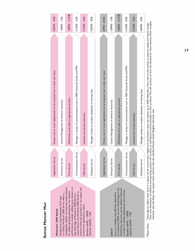
WIN
DO
WS
®20
00 S
ER
VE
R
Des
igne
d to
hel
p bu
sine
sses
of a
ll si
zes
run
bett
er,W
indo
ws
2000
Ser
ver
offe
rs a
m
anag
eabl
e,re
liabl
e an
d in
tern
et-r
eady
sol
utio
nfo
r to
day’s
gro
win
g en
terp
rise
s.Fo
r op
timal
pe
rfor
man
ce,c
onsi
der
addi
ng m
ore
mem
ory
tota
ke a
dvan
tage
of W
indo
ws
2000
Ser
ver’s
robu
st fe
atur
e se
t.W
indo
ws
2000
Ser
ver
isin
tern
et-r
eady
and
pro
mis
es t
o ru
n to
day’s
and
tom
orro
w’s
appl
icat
ions
bet
ter.
Base
line:
64M
B –
128M
BO
ptim
al:2
56M
B –
1GB
Hou
ses
one
or m
ore
appl
icat
ions
to
be a
cces
sed
over
a w
ide
user
bas
e
Cen
tral
Man
agem
ent
of n
etw
ork
reso
urce
s
Dis
trib
utes
pri
nt jo
bs t
o ap
prop
riat
e pr
inte
rs
Man
ages
a v
arie
ty o
f com
mun
icat
ions
suc
h as
PBX
,Voi
cem
ail,
Emai
l,an
d V
PN
Inte
rnet
and
intr
anet
sol
utio
ns
Man
ages
sim
ple
to c
ompl
ex d
atab
ases
of v
aryi
ng s
izes
App
licat
ion
Serv
er
Dir
ecto
ry S
erve
r
Prin
t Se
rver
Com
mun
icat
ion
Serv
er
Web
Ser
ver
Dat
abas
e Se
rver
256M
B –
4GB
128M
B –
1GB
128M
B –
512M
B
512M
B –
2GB
512M
B –
2GB
256M
B –
4GB
* Pl
ease
Not
e:T
hese
figu
res
refle
ct w
ork
done
in a
typ
ical
ser
ver
envi
ronm
ent.
Hig
her-
end
wor
ksta
tion
task
s m
ay r
equi
re u
p to
4G
B.N
atur
ally,
a ch
art
such
as
this
evo
lves
as
mem
ory
need
s an
d tr
ends
cha
nge.
Ove
r tim
e,de
velo
pers
of s
oftw
are
and
oper
atin
g sy
stem
s w
ill c
ontin
ue t
o ad
d fe
atur
es a
nd fu
nctio
nalit
y to
the
ir p
rodu
cts.
Thi
s w
ill c
ontin
ue t
o dr
ive
the
dem
and
for
mor
e m
emor
y.M
ore
com
plex
ch
arac
ter
sets
,lik
e K
anji,
may
req
uire
mor
e m
emor
y th
an t
he s
tand
ard
Rom
an b
ased
(En
glis
h) c
hara
cter
set
s.
LIN
UX
®
Linu
x is
a r
elia
ble,
cost
-effe
ctiv
e al
tern
ativ
e to
tra
ditio
nal U
NIX
ser
vers
.Dep
endi
ng o
n th
edi
stri
butio
n,th
e Li
nux
serv
er p
latfo
rm fe
atur
esa
vari
ety
of u
tiliti
es,a
pplic
atio
ns,a
nd s
ervi
ces.
Base
line:
64M
B –
128M
BO
ptim
al:2
56M
B –
1GB
Hou
ses
one
or m
ore
appl
icat
ions
to
be a
cces
sed
over
a w
ide
user
bas
e
Cen
tral
Man
agem
ent
of n
etw
ork
reso
urce
s
Dis
trib
utes
pri
nt jo
bs t
o ap
prop
riat
e pr
inte
rs
Man
ages
a v
arie
ty o
f com
mun
icat
ions
suc
h as
PBX
,Voi
cem
ail,
Emai
l,an
d V
PN
Inte
rnet
and
intr
anet
sol
utio
ns
Man
ages
sim
ple
to c
ompl
ex d
atab
ases
of v
aryi
ng s
izes
App
licat
ion
Serv
er
Dir
ecto
ry S
erve
r
Prin
t Se
rver
Com
mun
icat
ion
Serv
er
Web
Ser
ver
Dat
abas
e Se
rver
64M
B –
64G
B
128M
B –
1GB
128M
B –
512M
B
512M
B –
2GB
512M
B –
2GB
256M
B –
4GB
SE
RV
ER
ME
MO
RYM
AP

A CLOSER LOOK
WHAT MEMORY LOOKS LIKE
WHERE MEMORY COMES FROM
WHERE MEMORY GOES IN THE COMPUTER

21
THE ULTIMATE MEMORY GUIDE KINGSTON TECHNOLOGYA CLOSER LOOK
Memory comes in a variety of sizes and shapes. In general, it looks like a flat greenstick with little black cubes on it. Obviously, there’s a lot more to memory than that.The illustration below shows a typical memory module and points out some of itsmost important features.
WHAT MEMORY LOOKS LIKE
PCB (PRINTED CIRCUIT BOARD) The green board that all the memory chips sit on is actually made up of several layers. Each layer contains traces and circuitry, which facilitate the movement ofdata. In general, higher quality memory modules use PCBs with more layers. Themore layers a PCB has, the more space there is between traces. The more spacethere is between traces, the lesser the chance of noise interference. This makes themodule much more reliable.
DRAM (DYNAMIC RANDOM ACCESS MEMORY)DRAM is the most common form of RAM. It’s called “dynamic” RAM because it canonly hold data for a short period of time and must be refreshed periodically. Mostmemory chips have black or chrome coating, or packaging, to protect their circuitry. The following section titled “Chip Packaging” shows pictures of chipshoused in different types of chip packages.
A closer look at a
168-pin SDRAM DIMM.
Internal Trace Layer
Contact Fingers
PCB (Printed Circuit Board)
DRAM
CONTACT FINGERS
The contact fingers, sometimes referred to as “connectors” or “leads,” plug into thememory socket on the system board, enabling information to travel from the systemboard to the memory module and back. On some memory modules, these leads areplated with tin while on others, the leads are made of gold. To learn more about thetype of metal on the contacts, refer to the section titled, “Tin versus Gold” on page 67.
INTERNAL TRACE LAYER
The magnifying glass shows a layer of the PCB stripped away to reveal the tracesetched in the board. Traces are like roads the data travels on. The width and curvature of these traces as well as the distance between them affect both the speed and the reliability of the overall module. Experienced designers arrange, or “lay out,” the traces to maximize speed and reliability and minimize interference.
CHIP PACKAGING
The term “chip packaging” refers to the material coating around the actual silicon.Today’s most common packaging is called TSOP (Thin Small Outline Package).Some earlier chip designs used DIP (Dual In-line Package) packaging and SOJ(Small Outline J-lead). Newer chips, such as RDRAM use CSP (Chip Scale Package).Take a look at the different chip packages below, so you can see how they differ.
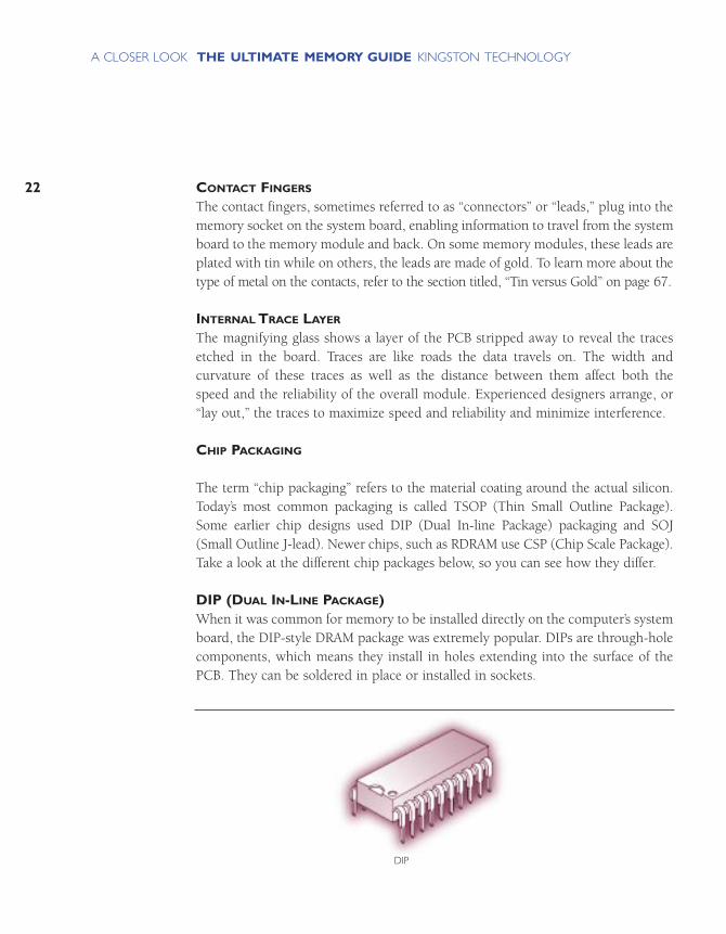
DIP (DUAL IN-LINE PACKAGE)When it was common for memory to be installed directly on the computer’s systemboard, the DIP-style DRAM package was extremely popular. DIPs are through-holecomponents, which means they install in holes extending into the surface of thePCB. They can be soldered in place or installed in sockets.
22
THE ULTIMATE MEMORY GUIDE KINGSTON TECHNOLOGYA CLOSER LOOK
DIP

23
THE ULTIMATE MEMORY GUIDE KINGSTON TECHNOLOGYA CLOSER LOOK
SOJ (SMALL OUTLINE J-LEAD)SOJ packages got their name because the pins coming out of the chip are shapedlike the letter “J”. SOJs are surface-mount components – that is, they mount directlyonto the surface of the PCB.
TSOP (THIN SMALL OUTLINE PACKAGE)TSOP packaging, another surface-mount design, got its name because the packagewas much thinner than the SOJ design. TSOPs were first used to make thin creditcard modules for notebook computers.
TSOP
SOJ
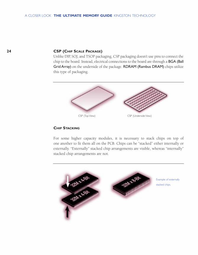
CSP (CHIP SCALE PACKAGE)Unlike DIP, SOJ, and TSOP packaging, CSP packaging doesn’t use pins to connect thechip to the board. Instead, electrical connections to the board are through a BGA (BallGrid Array) on the underside of the package. RDRAM (Rambus DRAM) chips utilizethis type of packaging.
CHIP STACKING
For some higher capacity modules, it is necessary to stack chips on top of one another to fit them all on the PCB. Chips can be “stacked” either internally orexternally. “Externally” stacked chip arrangements are visible, whereas “internally”stacked chip arrangements are not.
24
THE ULTIMATE MEMORY GUIDE KINGSTON TECHNOLOGYA CLOSER LOOK
Example of externally
stacked chips.
CSP (Top View) CSP (Underside View)
25
THE ULTIMATE MEMORY GUIDE KINGSTON TECHNOLOGYA CLOSER LOOK
WHERE MEMORY COMES FROM
MAKING THE CHIP
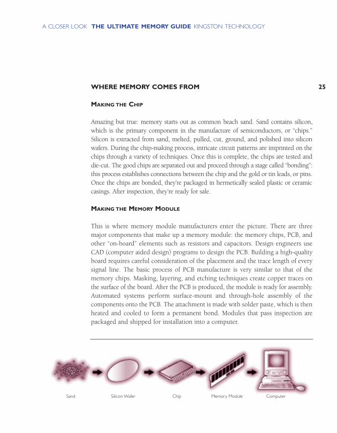
Amazing but true: memory starts out as common beach sand. Sand contains silicon,which is the primary component in the manufacture of semiconductors, or “chips.”Silicon is extracted from sand, melted, pulled, cut, ground, and polished into siliconwafers. During the chip-making process, intricate circuit patterns are imprinted on thechips through a variety of techniques. Once this is complete, the chips are tested anddie-cut. The good chips are separated out and proceed through a stage called “bonding”:this process establishes connections between the chip and the gold or tin leads, or pins.Once the chips are bonded, they’re packaged in hermetically sealed plastic or ceramiccasings. After inspection, they’re ready for sale.
MAKING THE MEMORY MODULE
This is where memory module manufacturers enter the picture. There are threemajor components that make up a memory module: the memory chips, PCB, andother “on-board” elements such as resistors and capacitors. Design engineers useCAD (computer aided design) programs to design the PCB. Building a high-qualityboard requires careful consideration of the placement and the trace length of everysignal line. The basic process of PCB manufacture is very similar to that of thememory chips. Masking, layering, and etching techniques create copper traces onthe surface of the board. After the PCB is produced, the module is ready for assembly.Automated systems perform surface-mount and through-hole assembly of thecomponents onto the PCB. The attachment is made with solder paste, which is thenheated and cooled to form a permanent bond. Modules that pass inspection arepackaged and shipped for installation into a computer.
Sand Silicon Wafer Chip Memory Module Computer

WHERE MEMORY GOES IN THE COMPUTER
Originally, memory chips were connected directly to the computer’s motherboardor system board. But then space on the board became an issue. The solution was to solder memory chips to a small modular circuit board – that is, aremovable module that inserts into a socket on the motherboard. This moduledesign was called a SIMM (single in-line memory module), and it saved a lot ofspace on the motherboard. For example, a set of four SIMMs might contain a totalof 80 memory chips and take up about 9 square inches of surface area on the motherboard. Those same 80 chips installed flat on the motherboard would takeup more than 21 square inches on the motherboard.
These days, almost all memory comes in the form of memory modules and isinstalled in sockets located on the system motherboard. Memory sockets are easyto spot because they are normally the only sockets of their size on the board.Because it’s critical to a computer’s performance for information to travel quicklybetween memory and the processor(s), the sockets for memory are typically locatednear the CPU.
26
THE ULTIMATE MEMORY GUIDE KINGSTON TECHNOLOGYA CLOSER LOOK
High-end Workstation Mini-Tower PC Notebook Printer
Examples of where
memory can be installed.

27
THE ULTIMATE MEMORY GUIDE KINGSTON TECHNOLOGYA CLOSER LOOK
MEMORY BANKS AND BANK SCHEMAS
Memory in a computer is usually designed and arranged in memory banks. A memorybank is a group of sockets or modules that make up one logical unit. So, memorysockets that are physically arranged in rows may be part of one bank or dividedinto different banks. Most computer systems have two or more memory banks –usually called bank A, bank B, and so on. And each system has rules or conven-tions on how memory banks should be filled. For example, some computer systemsrequire all the sockets in one bank to be filled with the same capacity module.Some computers require the first bank to house the highest capacity modules. Ifthe configuration rules aren’t followed, the computer may not start up or it may notrecognize all the memory in the system.
You can usually find the memory configuration rules specific to your computer system in the computer’s system manual. You can also use what’s called a memoryconfigurator. Most third-party memory manufacturers offer free memory configu-rators available in printed form, or accessible electronically via the Web. Memoryconfigurators allow you to look up your computer and find the part numbers andspecial memory configuration rules that apply to your system.
Kingston Technology’s memory configurator includes “bank schema” drawings fordifferent computer systems (a bank schema drawing depicts the sockets in the system), along with special instructions that list any unusual configuration rulesthat apply to a the systems. For more information on this, see “What kind of memoryis compatible with my system?” on page 74 and “How to Read a Bank Schema” onpage 75.

HOW MEMORY WORKS
HOW MEMORY WORKS WITH THE PROCESSOR
MAXIMIZING PERFORMANCE
31
THE ULTIMATE MEMORY GUIDE KINGSTON TECHNOLOGYHOW MEMORY WORKS
Earlier, we talked about how memory holds information in a place where the CPUcan get to it quickly. Let’s look at that process in more detail.
HOW MEMORY WORKS WITH THE PROCESSOR
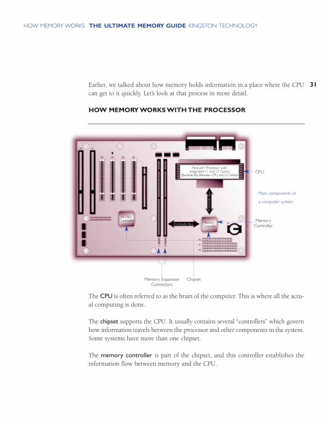
The CPU is often referred to as the brain of the computer. This is where all the actu-al computing is done.
The chipset supports the CPU. It usually contains several “controllers” which governhow information travels between the processor and other components in the system.Some systems have more than one chipset.
The memory controller is part of the chipset, and this controller establishes theinformation flow between memory and the CPU.
Main components of
a computer system.
PCI BusController
Pentium® Processor with Integrated L1 and L2 Cache
(Backside Bus Between CPU and L2 Cache)
MemoryController
Frontside Bus
Memory ExpansionConnectors
Chipset
Fron
tsid
e Bu
s
MemoryController
CPU

A bus is a data path in a computer, consisting of various parallel wires to which theCPU, memory, and all input/output devices are connected. The design of the bus,or bus architecture, determines how much and how fast data can move across the motherboard. There are several different kinds of busses in a system, depending onwhat speeds are required for those particular components. The memory bus runsfrom the memory controller to the computer’s memory sockets. Newer systemshave a memory bus architecture in which a frontside bus (FSB) runs from the CPUto main memory and a backside bus (BSB) which runs from the memory controllerto L2 cache.
MEMORY SPEED
When the CPU needs information from memory, it sends out a request that is managed by the memory controller. The memory controller sends the request tomemory and reports to the CPU when the information will be available for it toread. This entire cycle – from CPU to memory controller to memory and back tothe CPU – can vary in length according to memory speed as well as other factors,such as bus speed.
Memory speed is sometimes measured in Megahertz (MHz), or in terms of accesstime – the actual time required to deliver data – measured in nanoseconds (ns).Whether measured in Megahertz or nanoseconds, memory speed indicates howquickly the memory module itself can deliver on a request once that request is received.
32
THE ULTIMATE MEMORY GUIDE KINGSTON TECHNOLOGYHOW MEMORY WORKS

33
THE ULTIMATE MEMORY GUIDE KINGSTON TECHNOLOGYHOW MEMORY WORKS
ACCESS TIME (NANOSECONDS)
Access time measures from when the memory module receives a data request to whenthat data becomes available. Memory chips and modules used to be marked withaccess times ranging from 80ns to 50ns. With access time measurements (that is,measurements in nanoseconds), lower numbers indicate faster speeds.
In this example, the
memory controller
requests data from
memory and memory
reacts to the request in
70ns.The CPU receives
the data in approximately
125ns. So, the total time
from when the CPU first
requests information to
when it actually receives
the information can be up
to 195ns when using a
70ns memory module.
This is because it takes
time for the memory
controller to manage the
information flow, and the
information needs to
travel from the memory
module to the CPU on
the bus.
72-Pin, 70ns SIMMs
CPU
125ns
70ns
MEGAHERTZ (MHZ)
Beginning with Synchronous DRAM technology, memory chips had the ability tosynchronize themselves with the computer’s system clock, making it easier tomeasure speed in megahertz, or millions of cycles per second. Because this is thesame way speed is measured in the rest of the system, it makes it easier to comparethe speeds of different components and synchronize their functions. In order tounderstand speed better, it’s important to understand the system clock.
SYSTEM CLOCK
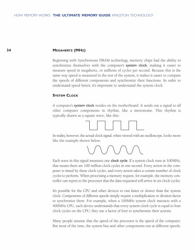
A computer’s system clock resides on the motherboard. It sends out a signal to allother computer components in rhythm, like a metronome. This rhythm is typically drawn as a square wave, like this:
In reality, however, the actual clock signal, when viewed with an oscilloscope, looks morelike the example shown below.
Each wave in this signal measures one clock cycle. If a system clock runs at 100MHz,that means there are 100 million clock cycles in one second. Every action in the com-puter is timed by these clock cycles, and every action takes a certain number of clockcycles to perform. When processing a memory request, for example, the memory con-troller can report to the processor that the data requested will arrive in six clock cycles.
It’s possible for the CPU and other devices to run faster or slower than the systemclock. Components of different speeds simply require a multiplication or division factorto synchronize them. For example, when a 100MHz system clock interacts with a400MHz CPU, each device understands that every system clock cycle is equal to fourclock cycles on the CPU; they use a factor of four to synchronize their actions.
Many people assume that the speed of the processor is the speed of the computer.But most of the time, the system bus and other components run at different speeds.
34
THE ULTIMATE MEMORY GUIDE KINGSTON TECHNOLOGYHOW MEMORY WORKS

35
THE ULTIMATE MEMORY GUIDE KINGSTON TECHNOLOGYHOW MEMORY WORKS
MAXIMIZING PERFORMANCE
Computer processor speeds have been increasing rapidly over the past severalyears. Increasing the speed of the processor increases the overall performance of thecomputer. However, the processor is only one part of the computer, and it stillrelies on other components in a system to complete functions. Because all the infor-mation the CPU will process must be written to or read from memory, the overallperformance of a system is dramatically affected by how fast information can travelbetween the CPU and main memory.
So, faster memory technologies contribute a great deal to overall system performance.But increasing the speed of the memory itself is only part of the solution. The timeit takes for information to travel between memory and the processor is typicallylonger than the time it takes for the processor to perform its functions. The technologies and innovations described in this section are designed to speed up thecommunication process between memory and the processor.
CACHE MEMORY
Cache memory is a relatively small amount (normally less than 1MB) of high speedmemory that resides very close to the CPU. Cache memory is designed to supplythe CPU with the most frequently requested data and instructions. Because retriev-ing data from cache takes a fraction of the time that it takes to access it from mainmemory, having cache memory can save a lot of time. If the information is not incache, it still has to be retrieved from main memory, but checking cache memorytakes so little time, it’s worth it. This is analogous to checking your refrigerator forthe food you need before running to the store to get it: it’s likely that what you needis there; if not, it only took a moment to check.
The concept behind caching is the “80/20” rule, which states that of all the programs, information, and data on your computer, about 20% of it is used about80% of the time. (This 20% data might include the code required for sending ordeleting email, saving a file onto your hard drive, or simply recognizing which keysyou’ve touched on your keyboard.) Conversely, the remaining 80% of the data inyour system gets used about 20% of the time. Cache memory makes sense becausethere’s a good chance that the data and instructions the CPU is using now will beneeded again.

HOW CACHE MEMORY WORKS
Cache memory is like a “hot list” of instructions needed by the CPU. The memorycontroller saves in cache each instruction the CPU requests; each time the CPU getsan instruction it needs from cache – called a “cache hit” – that instruction moves tothe top of the “hot list.” When cache is full and the CPU calls for a new instruction,the system overwrites the data in cache that hasn’t been used for the longest periodof time. This way, the high priority information that’s used continuously stays incache, while the less frequently used information drops out.
LEVELS OF CACHE
Today, most cache memory is incorporated into the processor chip itself; however,other configurations are possible. In some cases, a system may have cache locatedinside the processor, just outside the processor on the motherboard, and/or it may havea memory cache socket near the CPU, which can contain a cache memory module.Whatever the configuration, any cache memory component is assigned a “level”according to its proximity to the processor. For example, the cache that is closest tothe processor is called Level 1 (L1) Cache, the next level of cache is numbered L2, thenL3, and so on. Computers often have other types of caching in addition to cache mem-ory. For example, sometimes the system uses main memory as a cache for the harddrive. While we won’t discuss these scenarios here, it’s important to note that the termcache can refer specifically to memory and to other storage technologies as well.
36
THE ULTIMATE MEMORY GUIDE KINGSTON TECHNOLOGYHOW MEMORY WORKS
It can take as long as
195ns for main memory
to satisfy a memory
request from the CPU.
External cache can satisfy
a memory request from
the CPU in as little as 45ns.
Main Memory
CPU with 16KB Internal Cache
(Primary Level 1)
256KB External Cache(Secondary Level 2)
You might wonder:
if having cache memory
near the processor is so
beneficial, why isn’t cache
memory used for all of
main memory? For one
thing, cache memory
typically uses a type of
memory chip called
SRAM (Static RAM),
which is more expensive
and requires more space
per megabyte than the
DRAM typically used for
main memory. Also, while
cache memory does
improve overall system
performance, it does so
up to a point.The real
benefit of cache memory
is in storing the most
frequently-used instruc-
tions. A larger cache
would hold more data,
but if that data isn’t
needed frequently, there’s
little benefit to having it
near the processor.
37
THE ULTIMATE MEMORY GUIDE KINGSTON TECHNOLOGYHOW MEMORY WORKS
SYSTEM BOARD LAYOUT
As you’ve probably figured out, the placement of memory modules on the systemboard has a direct effect on system performance. Because local memory must holdall the information the CPU needs to process, the speed at which the data can travelbetween memory and the CPU is critical to the overall performance of the system.And because exchanges of information between the CPU and memory are so intricately timed, the distance between the processor and the memory becomesanother critical factor in performance.
INTERLEAVING
The term interleaving refers to a process in which the CPU alternates communicationbetween two or more memory banks. Interleaving technology is typically used inlarger systems such as servers and workstations. Here’s how it works: every time theCPU addresses a memory bank, the bank needs about one clock cycle to “reset” itself.The CPU can save processing time by addressing a second bank while the first bankis resetting. Interleaving can also function within the memory chips themselves toimprove performance. For example, the memory cells inside SDRAM chip are divided into two independent cell banks, which can be activated simultaneously.Interleaving between the two cell banks produces a continuous flow of data. This cutsdown the length of the memory cycle and results in faster transfer rates.

BURSTING
Bursting is another time-saving technology. The purpose of bursting is to provide theCPU with additional data from memory based on the likelihood that it will be needed.So, instead of the CPU retrieving information from memory one piece of at a time, itgrabs a block of information from several consecutive addresses in memory. This savestime because there’s a statistical likelihood that the next data address the processor willrequest will be sequential to the previous one. This way, the CPU gets the instructionsit needs without having to send an individual request for each one. Bursting can workwith many different types of memory and can function when reading or writing data.
PIPELINING
Pipelining is a computer processing technique where a task is divided into a seriesof stages with some of the work completed at each stage. Through the division of a larger task into smaller, overlapping tasks, pipelining is used to improve performance beyond what is possible with non-pipelined processing. Once theflow through a pipeline is started, execution rate of the instructions is high, in spiteof the number of stages through which they progress.
38
THE ULTIMATE MEMORY GUIDE KINGSTON TECHNOLOGYHOW MEMORY WORKS
Both bursting and
pipelining became popular
at about the same time
that EDO technology
became available. EDO
chips that featured these
functions were called
“Burst EDO” or “Pipeline
Burst EDO” chips.
HOW MUCH MEMORY IS ON A MODULE?
BITS AND BYTES
CPU AND MEMORY REQUIREMENTS
CALCULATING THE CAPACITY OF A MODULE
STACKING
41
THE ULTIMATE MEMORY GUIDE KINGSTON TECHNOLOGYHOW MUCH MEMORY
IS ON A MODULE?
Up to now, we’ve discussed some of the technical attributes of memory and howmemory functions in a system. What’s left are the technical details – the “bits andbytes,“ as they say. This section covers the binary numbering system, which formsthe basis of computing, and calculation of a memory module’s capacity.
BITS AND BYTES
Computers speak in a “code” called machine language, which uses only two numerals:0 and 1. Different combinations of 0s and 1s form what are called binary numbers.These binary numbers form instructions for the chips and microprocessors that drivecomputing devices – such as computers, printers, hard disk drives, and so on.
You may have heard the terms “bit” and “byte.” Both of these are units of informationthat are important to computing. The term bit is short for “binary digit.” As the namesuggests, a bit represents a single digit in a binary number; a bit is the smallest unitof information used in computing and can have a value of either 1 or a 0. A byteconsists of 8 bits. Almost all specifications of your computer’s capabilities are represented in bytes. For example, memory capacity, data-transfer rates, and data-storage capacity are all measured in bytes or multiples thereof (such as kilobytes,megabytes, or gigabytes).
This discussion of bits and bytes becomes very relevant when it comes to computingdevices and components working together. Here, we’ll address specifically how bitsand bytes form the basis of measuring memory component performance and interactionwith other devices like the CPU.
CPU AND MEMORY REQUIREMENTS
A computer’s CPU (central processing unit) processes data in 8-bit chunks. Thosechunks, as we learned in the previous section, are commonly referred to as bytes.Because a byte is the fundamental unit of processing, the CPU’s processing power isoften described in terms of the maximum number of bytes it can process at any giventime. For example, Pentium and PowerPC microprocessors currently are 64-bitCPUs, which means they can simultaneously process 64 bits, or 8 bytes, at a time.
Each transaction between the CPU and memory is called a bus cycle. The numberof data bits a CPU can transfer during a single bus cycle affects a computer’s performance and dictates what type of memory the computer requires. Most desktopcomputers today use 168-pin DIMMs, which support 64-bit data paths. Earlier 72-pin SIMMs supported 32-bit data paths, and were originally used with 32-bitCPUs. When 32-bit SIMMs were used with 64-bit processors, they had to beinstalled in pairs, with each pair of modules making up a memory bank. The CPU communicated with the bank of memory as one logical unit.
Interestingly, RIMM modules, which are newer than DIMMs, use smaller 16-bit datapaths; however they transmit information very rapidly, sending several packets ofdata at a time. RIMM modules use pipelining technology to send four 16-bit packetsat a time to a 64-bit CPU, so information still gets processed in 64-bit chunks.
42
THE ULTIMATE MEMORY GUIDE KINGSTON TECHNOLOGYHOW MUCH MEMORY
IS ON A MODULE?
43
THE ULTIMATE MEMORY GUIDE KINGSTON TECHNOLOGYHOW MUCH MEMORY
IS ON A MODULE?
CALCULATING THE CAPACITY OF A MODULE
Memory holds the information that the CPU needs to process. The capacity ofmemory chips and modules are described in megabits (millions of bits) andmegabytes (millions of bytes). When trying to figure out how much memory youhave on a module, there are two important things to remember:
A module consists of a group of chips. If you add together the capacities of all the chipson the module, you get the total capacity of the module. Exceptions to this rule are:
• If some of the capacity is being used for another function, such as error checking.
• If some of the capacity is not being used, for example some chips may have extrarows to be used as back-ups. (This isn’t common.)
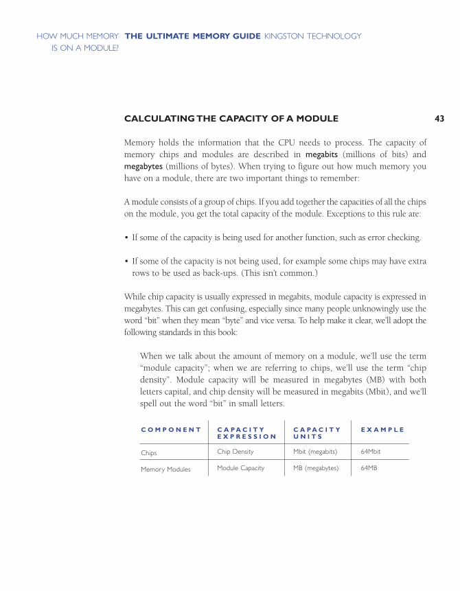
While chip capacity is usually expressed in megabits, module capacity is expressed inmegabytes. This can get confusing, especially since many people unknowingly use theword “bit” when they mean “byte” and vice versa. To help make it clear, we’ll adopt thefollowing standards in this book:
When we talk about the amount of memory on a module, we’ll use the term“module capacity”; when we are referring to chips, we’ll use the term “chipdensity”. Module capacity will be measured in megabytes (MB) with both letters capital, and chip density will be measured in megabits (Mbit), and we’llspell out the word “bit” in small letters.
C O M P O N E N T
Chips
Memory Modules
C A P A C I T YE X P R E S S I O N
Chip Density
Module Capacity
C A P A C I T YU N I T S
Mbit (megabits)
MB (megabytes)
E X A M P L E
64Mbit
64MB
CHIP DENSITY
Each memory chip is a matrix of tiny cells. Each cell holds one bit of information.Memory chips are often described by how much information they can hold. We callthis chip density. You may have encountered examples of chip densities, such as“64Mbit SDRAM” or “8M by 8”. A 64Mbit chip has 64 million cells and is capableof holding 64 million bits of data. The expression “8M by 8” describes one kind of64Mbit chip in more detail.
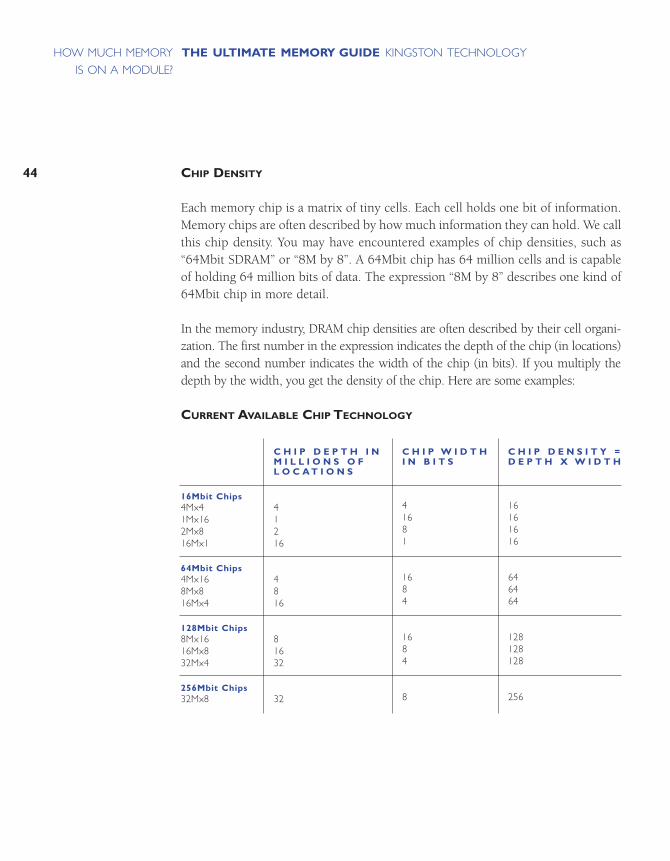
In the memory industry, DRAM chip densities are often described by their cell organi-zation. The first number in the expression indicates the depth of the chip (in locations)and the second number indicates the width of the chip (in bits). If you multiply thedepth by the width, you get the density of the chip. Here are some examples:
CURRENT AVAILABLE CHIP TECHNOLOGY
44
THE ULTIMATE MEMORY GUIDE KINGSTON TECHNOLOGYHOW MUCH MEMORY
IS ON A MODULE?
16Mbit Chips4Mx41Mx162Mx816Mx1
64Mbit Chips4Mx168Mx816Mx4
128Mbit Chips8Mx1616Mx832Mx4
256Mbit Chips32Mx8
C H I P D E P T H I NM I L L I O N S O FL O C A T I O N S
41216
4816
81632
32
C H I P W I D T HI N B I T S
41681
1684
1684
8
C H I P D E N S I T Y =D E P T H X W I D T H
16161616
646464
128128128
256
45
THE ULTIMATE MEMORY GUIDE KINGSTON TECHNOLOGYHOW MUCH MEMORY
IS ON A MODULE?
MODULE CAPACITY
It’s easy to calculate the capacity of a memory module if you know the capacities ofthe chips on it. If there are eight 64Mbit chips, it’s a 512Mbit module. However,because the capacity of a module is described in megabytes, not megabits, you haveto convert bits to bytes. To do this, divide the number of bits by 8. In the case of the512Mbit module:
512Mbits= 64MB
8 bits per byte
You may hear standard memory modules in the industry being described as:“4Mx32” (that is, “4 Meg by 32”), or “16Mx64” (“16 Meg by 64”). In these cases,you can calculate the capacity of the module exactly as if it were a chip:
4Mx32 is 128Mbits. 16Mx64 is 1024Mbits.
128Mbits = 16MB module
1024Mbits = 128MB module
8 bits per byte 8 bits per byte
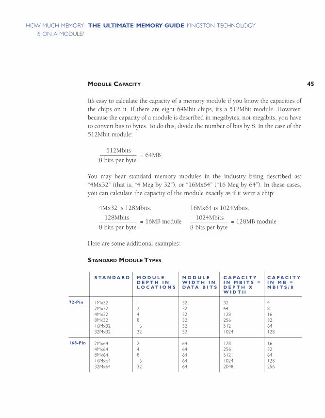
Here are some additional examples:
STANDARD MODULE TYPES
72-Pin
168-Pin
S T A N D A R D
1Mx322Mx324Mx328Mx3216Mx3232Mx32
2Mx644Mx648Mx6416Mx6432Mx64
M O D U L ED E P T H I NL O C A T I O N S
12481632
2481632
M O D U L EW I D T H I ND A T A B I T S
323232323232
6464646464
C A P A C I T YI N M B I T S =D E P T H XW I D T H
32641282565121024
12825651210242048
C A P A C I T YI N M B =M B I T S / 8
48163264128
163264128256
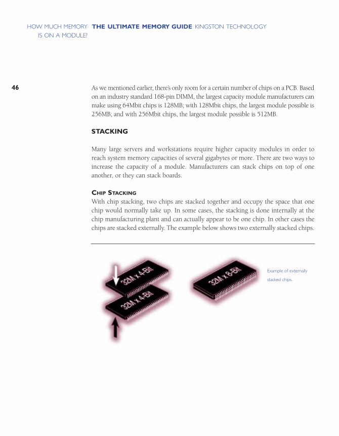
As we mentioned earlier, there’s only room for a certain number of chips on a PCB. Basedon an industry standard 168-pin DIMM, the largest capacity module manufacturers canmake using 64Mbit chips is 128MB; with 128Mbit chips, the largest module possible is256MB; and with 256Mbit chips, the largest module possible is 512MB.
STACKING
Many large servers and workstations require higher capacity modules in order toreach system memory capacities of several gigabytes or more. There are two ways toincrease the capacity of a module. Manufacturers can stack chips on top of oneanother, or they can stack boards.
CHIP STACKING
With chip stacking, two chips are stacked together and occupy the space that onechip would normally take up. In some cases, the stacking is done internally at thechip manufacturing plant and can actually appear to be one chip. In other cases thechips are stacked externally. The example below shows two externally stacked chips.
46
THE ULTIMATE MEMORY GUIDE KINGSTON TECHNOLOGYHOW MUCH MEMORY
IS ON A MODULE?
Example of externally
stacked chips.

47
THE ULTIMATE MEMORY GUIDE KINGSTON TECHNOLOGYHOW MUCH MEMORY
IS ON A MODULE?
BOARD STACKING
As you might expect, board stacking involves putting two memory module printedcircuit boards (PCBs) together. With board stacking, a secondary board mounts ontothe primary board, which fits into the memory socket on the system motherboard.
Example of a
stacked module.
Primary Board
FinishedStacked Module
Secondary Board
DIFFERENT KINDS OF MEMORY
MODULE FORM FACTORS
MAJOR CHIP TECHNOLOGIES
MEMORY TECHNOLOGIES FOR VIDEO OR GRAPHICS PROCESSING
OTHER MEMORY TECHNOLOGIES YOU MAY HAVE HEARD ABOUT
ERROR CHECKING
OTHER SPECIFICATIONS

51
THE ULTIMATE MEMORY GUIDE KINGSTON TECHNOLOGYDIFFERENT KINDS
OF MEMORY
Some people like to know a lot about the computer systems they own – or are considering buying – just because. They’re like that. It’s what makes them tick.Some people never find out about their systems and like it that way. Still other people– most of us, in fact – find out about their systems when they have to – when something goes wrong, or when they want to upgrade it. It’s important to note thatmaking a choice about a computer system – and its memory features – will affectthe experience and satisfaction you derive from the system. This chapter is here tomake you smarter about memory so that you can get more out of the system you’repurchasing or upgrading.
MODULE FORM FACTORS
The easiest way to categorize memory is by form factor. The form factor of anymemory module describes its size and pin configuration. Most computer systemshave memory sockets that can accept only one form factor. Some computer systemsare designed with more than one type of memory socket, allowing a choice betweentwo or more form factors. Such designs are usually a result of transitional periodsin the industry when it’s not clear which form factors will gain predominance or bemore available.

SIMMS
As previously mentioned, the term SIMM stands for Single In-Line Memory Module.With SIMMs, memory chips are soldered onto a modular printed circuit board(PCB), which inserts into a socket on the system board.
The first SIMMs transferred 8 bits of data at a time. Later, as CPUs began to readdata in 32-bit chunks, a wider SIMM was developed, which could supply 32 bitsof data at a time. The easiest way to differentiate between these two different kindsof SIMMs was by the number of pins, or connectors. The earlier modules had 30pins and the later modules had 72 pins. Thus, they became commonly referred toas 30-pin SIMMs and 72-pin SIMMs.
Another important difference between 30-pin and 72-pin SIMMs is that 72-pinSIMMs are 3/4 of an inch (about 1.9 centimeters) longer than the 30-pin SIMMsand have a notch in the lower middle of the PCB. The graphic below compares thetwo types of SIMMs and indicates their data widths.
52
THE ULTIMATE MEMORY GUIDE KINGSTON TECHNOLOGYDIFFERENT KINDS
OF MEMORY
41/4" 72-Pin SIMM
31/2" 30-Pin SIMM
Comparison of a 30-pin
and a 72-pin SIMM.
53
THE ULTIMATE MEMORY GUIDE KINGSTON TECHNOLOGYDIFFERENT KINDS
OF MEMORY
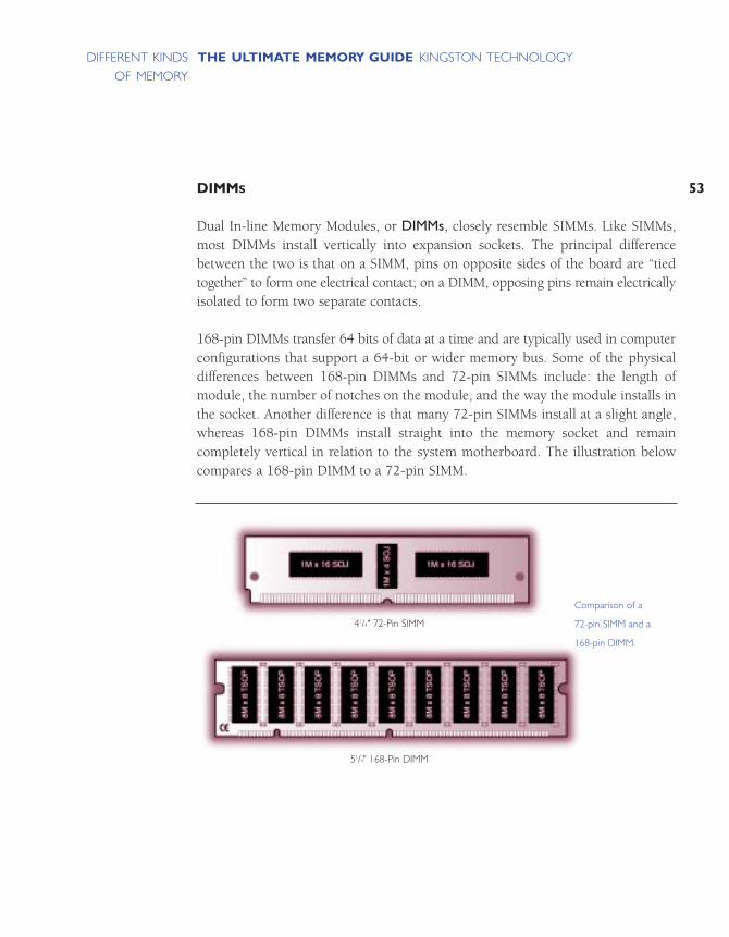
DIMMS
Dual In-line Memory Modules, or DIMMs, closely resemble SIMMs. Like SIMMs,most DIMMs install vertically into expansion sockets. The principal differencebetween the two is that on a SIMM, pins on opposite sides of the board are “tiedtogether” to form one electrical contact; on a DIMM, opposing pins remain electricallyisolated to form two separate contacts.
168-pin DIMMs transfer 64 bits of data at a time and are typically used in computerconfigurations that support a 64-bit or wider memory bus. Some of the physicaldifferences between 168-pin DIMMs and 72-pin SIMMs include: the length ofmodule, the number of notches on the module, and the way the module installs inthe socket. Another difference is that many 72-pin SIMMs install at a slight angle,whereas 168-pin DIMMs install straight into the memory socket and remain completely vertical in relation to the system motherboard. The illustration belowcompares a 168-pin DIMM to a 72-pin SIMM.
41/4" 72-Pin SIMM
51/4" 168-Pin DIMM
Comparison of a
72-pin SIMM and a
168-pin DIMM.
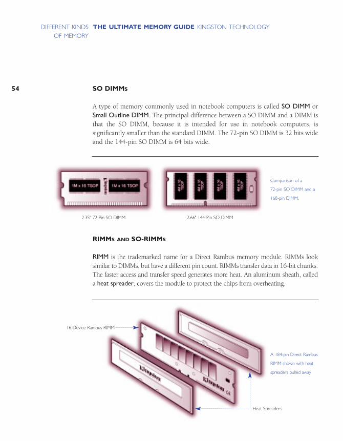
SO DIMMS
A type of memory commonly used in notebook computers is called SO DIMM orSmall Outline DIMM. The principal difference between a SO DIMM and a DIMM isthat the SO DIMM, because it is intended for use in notebook computers, is significantly smaller than the standard DIMM. The 72-pin SO DIMM is 32 bits wideand the 144-pin SO DIMM is 64 bits wide.
RIMMS AND SO-RIMMS
RIMM is the trademarked name for a Direct Rambus memory module. RIMMs looksimilar to DIMMs, but have a different pin count. RIMMs transfer data in 16-bit chunks.The faster access and transfer speed generates more heat. An aluminum sheath, calleda heat spreader, covers the module to protect the chips from overheating.
54
THE ULTIMATE MEMORY GUIDE KINGSTON TECHNOLOGYDIFFERENT KINDS
OF MEMORY
2.66" 144-Pin SO DIMM
Comparison of a
72-pin SO DIMM and a
168-pin DIMM.
A 184-pin Direct Rambus
RIMM shown with heat
spreaders pulled away.
2.35" 72-Pin SO DIMM
16-Device Rambus RIMM
Heat Spreaders

55
THE ULTIMATE MEMORY GUIDE KINGSTON TECHNOLOGYDIFFERENT KINDS
OF MEMORY
An SO-RIMM looks similar to an SO DIMM, but it uses Rambus technology.
PC CARD AND CREDIT CARD MEMORY
Before SO DIMMs became popular, most notebook memory was developed using proprietary designs. It is always more cost-effective for a system manufacturer to usestandard components, and at one point, it became popular to use the same “creditcard” like packaging for memory that is used on PC Cards today. Because the moduleslooked like PC Cards, many people thought the memory cards were the same as PCCards, and could fit into PC Card slots. At the time, this memory was described as“Credit Card Memory” because the form factor was the approximate size of a creditcard. Because of its compact form factor, credit card memory was ideal for notebookapplications where space is limited.
A 160-pin
SO-RIMM module.
On the surface, credit
card memory does
not resemble a typical
memory module
configuration. However,
on the inside you will
find standard TSOP
memory chips.
PC Cards use an
input/output protocol
that used to be referred
to as PCMCIA (Personal
Computer Memory
Card International
Association).This standard
is designed for attaching
input/output devices
such as network adapters,
fax/modems, or hard
drives to notebook
computers. Because
PC Card memory
resembles the types of
cards designed for use in
a notebook computer’s
PC Card slot, some
people have mistakenly
thought that the memory
modules could be used
in the PC Card slot.To
date, RAM has not been
packaged on a PCMCIA
card because the tech-
nology doesn’t allow the
processor to communicate
quickly enough with
memory. Currently, the
most common type of
memory on PC Card
modules is Flash memory.
Heat Spreader
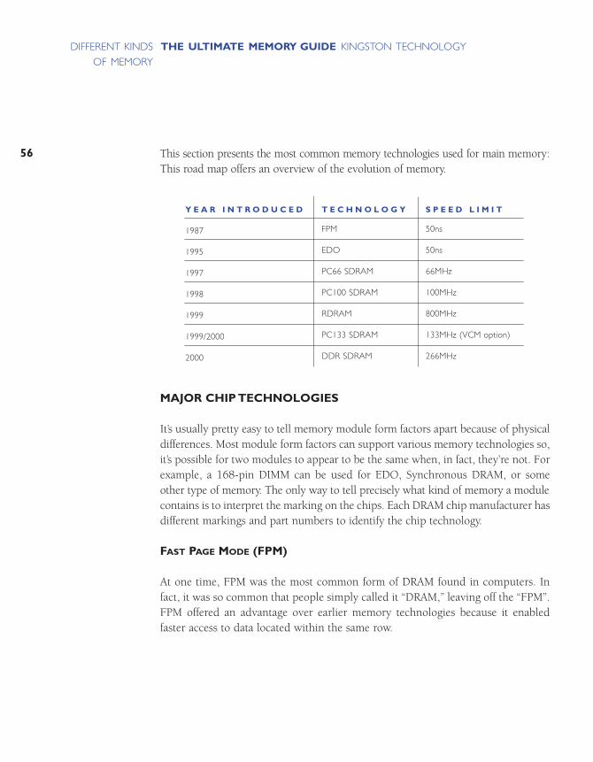
This section presents the most common memory technologies used for main memory:This road map offers an overview of the evolution of memory.
MAJOR CHIP TECHNOLOGIES
It’s usually pretty easy to tell memory module form factors apart because of physicaldifferences. Most module form factors can support various memory technologies so,it’s possible for two modules to appear to be the same when, in fact, they’re not. Forexample, a 168-pin DIMM can be used for EDO, Synchronous DRAM, or someother type of memory. The only way to tell precisely what kind of memory a modulecontains is to interpret the marking on the chips. Each DRAM chip manufacturer hasdifferent markings and part numbers to identify the chip technology.
FAST PAGE MODE (FPM)
At one time, FPM was the most common form of DRAM found in computers. Infact, it was so common that people simply called it “DRAM,” leaving off the “FPM”.FPM offered an advantage over earlier memory technologies because it enabledfaster access to data located within the same row.
56
THE ULTIMATE MEMORY GUIDE KINGSTON TECHNOLOGYDIFFERENT KINDS
OF MEMORY
Y E A R I N T R O D U C E D
1987
1995
1997
1998
1999
1999/2000
2000
T E C H N O L O G Y
FPM
EDO
PC66 SDRAM
PC100 SDRAM
RDRAM
PC133 SDRAM
DDR SDRAM
S P E E D L I M I T
50ns
50ns
66MHz
100MHz
800MHz
133MHz (VCM option)
266MHz

57
THE ULTIMATE MEMORY GUIDE KINGSTON TECHNOLOGYDIFFERENT KINDS
OF MEMORY
EXTENDED DATA OUT (EDO)
In 1995, EDO became the next memory innovation. It was similar to FPM, but witha slight modification that allowed consecutive memory accesses to occur muchfaster. This meant the memory controller could save time by cutting out a few stepsin the addressing process. EDO enabled the CPU to access memory 10 to 15%faster than with FPM.
SYNCHRONOUS DRAM (SDRAM)
In late 1996, SDRAM began to appear in systems. Unlike previous technologies,SDRAM is designed to synchronize itself with the timing of the CPU. This enablesthe memory controller to know the exact clock cycle when the requested data willbe ready, so the CPU no longer has to wait between memory accesses. SDRAMchips also take advantage of interleaving and burst mode functions, which makememory retrieval even faster. SDRAM modules come in several different speeds soas to synchronize to the clock speeds of the systems they’ll be used in. For example,PC66 SDRAM runs at 66MHz, PC100 SDRAM runs at 100MHz, PC133 SDRAMruns at 133MHz, and so on. Faster SDRAM speeds such as 200MHz and 266MHzare currently in development.
DOUBLE DATA RATE SYNCHRONOUS DRAM (DDR SDRAM)
DDR SDRAM, is a next-generation SDRAM technology. It allows the memory chip toperform transactions on both the rising and falling edges of the clock cycle. Forexample, with DDR SDRAM, a 100 or 133MHz memory bus clock rate yields aneffective data rate of 200MHz or 266MHz. Systems using DDR SDRAM are expectedto ship at the end of the year 2000.
DIRECT RAMBUS
Direct Rambus® is a new DRAM architecture and interface standard that challengestraditional main memory designs. Direct Rambus technology is extraordinarily fastcompared to older memory technologies. It transfers data at speeds up to 800MHzover a narrow 16-bit bus called a Direct Rambus Channel. This high-speed clockrate is possible due to a feature called “double clocked,” which allows operations tooccur on both the rising and falling edges of the clock cycle. Also, each memory deviceon an RDRAM module provides up to 1.6 gigabytes per second of bandwidth – twicethe bandwidth available with current 100MHz SDRAM.
In addition to chip technologies designed for use in main memory, there are alsospecialty memory technologies that have been developed for video applications.
MEMORY TECHNOLOGIES FOR VIDEO OR GRAPHICS PROCESSING
VIDEO RAM (VRAM)
VRAM is a video version of FPM technology. VRAM typically has two ports insteadof one, which allows the memory to allocate one channel to refreshing the screenwhile the other is focused on changing the images on the screen. This works muchmore efficiently than regular DRAM when it comes to video applications. However,since video memory chips are used in much lower quantities than main memorychips, they tend to be more expensive. So, a system designer may choose to use regular DRAM in a video subsystem, depending on whether cost or performance isthe design objective.
WINDOW RAM (WRAM)
WRAM is another type of dual-ported memory also used in graphics-intensive systems. It differs slightly from VRAM in that its dedicated display port is smallerand it supports EDO features.
SYNCHRONOUS GRAPHICS RAM (SGRAM)
SGRAM is a video-specific extension of SDRAM that includes graphics-specificread/write features. SGRAM also allows data to be retrieved and modified in blocks,instead of individually. This reduces the number of reads and writes that memorymust perform and increases the performance of the graphics controller by makingthe process more efficient.
BASE RAMBUS AND CONCURRENT RAMBUS
Before it even became a contender for main memory, Rambus technology was actually used in video memory. The current Rambus main memory technology iscalled Direct Rambus. Two earlier forms of Rambus are Base Rambus and ConcurrentRambus. These forms of Rambus have been used in specialty video applications insome workstations and video game systems like Nintendo 64 for several years.
58
THE ULTIMATE MEMORY GUIDE KINGSTON TECHNOLOGYDIFFERENT KINDS
OF MEMORY

59
THE ULTIMATE MEMORY GUIDE KINGSTON TECHNOLOGYDIFFERENT KINDS
OF MEMORY
OTHER MEMORY TECHNOLOGIES YOU MAY HAVE HEARD ABOUT
ENHANCED SDRAM (ESDRAM)
In order to increase the speed and efficiency of standard memory modules, somemanufacturers have incorporated a small amount of SRAM directly into the chip,effectively creating an on-chip cache. ESDRAM is essentially SDRAM, plus a smallamount of SRAM cache, which allows for burst operations of up to 200MHz. Justas with external cache memory, the goal of cache DRAM is to hold the most frequently used data in the SRAM cache to minimize accesses to the slower DRAM.One advantage of on-chip SRAM is that it enables a wider bus between the SRAMand DRAM, effectively increasing the bandwidth and speed of the DRAM.
FAST CYCLE RAM (FCRAM)
FCRAM, co-developed by Toshiba and Fujitsu, is intended for specialty applicationssuch as high-end servers, printers, and telecommunications switching systems. Itincludes memory array segmentation and internal pipelining that speed randomaccess and reduce power consumption.
SYNCLINK DRAM (SLDRAM)
Though considered obsolete today, SLDRAM was developed by a consortium ofDRAM manufacturers as an alternative to Rambus technology in the late 1990s.
VIRTUAL CHANNEL MEMORY (VCM)
Developed by NEC, VCM allows different “blocks” of memory to interface inde-pendently with the memory controller, each with its own buffer. This way, differentsystem tasks can be assigned their own “virtual channels,” and information related toone function does not share buffer space with other tasks occurring at the same time,making operations more efficient.
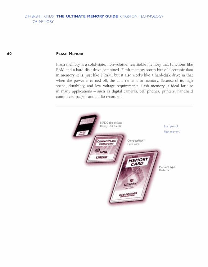
FLASH MEMORY
Flash memory is a solid-state, non-volatile, rewritable memory that functions likeRAM and a hard disk drive combined. Flash memory stores bits of electronic datain memory cells, just like DRAM, but it also works like a hard-disk drive in thatwhen the power is turned off, the data remains in memory. Because of its highspeed, durability, and low voltage requirements, flash memory is ideal for use in many applications – such as digital cameras, cell phones, printers, handheld computers, pagers, and audio recorders.
60
THE ULTIMATE MEMORY GUIDE KINGSTON TECHNOLOGYDIFFERENT KINDS
OF MEMORY
Examples of
Flash memory.
SSFDC (Solid StateFloppy Disk Card)
CompactFlashTM
Flash Card
PC Card Type IFlash Card
61
THE ULTIMATE MEMORY GUIDE KINGSTON TECHNOLOGYDIFFERENT KINDS
OF MEMORY
ERROR CHECKING
Ensuring the integrity of data stored in memory is an important aspect of memorydesign. Two primary means of accomplishing this are parity and error correctioncode (ECC).
Historically, parity has been the most commonly used data integrity method. Paritycan detect – but not correct – single-bit errors. Error Correction Code (ECC) is amore comprehensive method of data integrity checking that can detect and correctsingle-bit errors.
Fewer and fewer PC manufacturers are supporting data integrity checking in theirdesigns. This is due to a couple of factors. First, by eliminating support for paritymemory, which is more expensive than standard memory, manufacturers can lower theprice of their computers. Fortunately, this trend is complemented by the second factor: that is, the increased quality of memory components available from certainmanufacturers and, as a result, the relative infrequency of memory errors.
The type of data integrity checking depends on how a given computer system willbe used. If the computer is to play a critical role – as a server, for example – then acomputer that supports data integrity checking is an ideal choice. In general:
• Most computers designed for use as high-end servers support ECC memory. • Most low-cost computers designed for use at home or for small businesses support
non-parity memory.

PARITY
When parity is in use on a computer system, one parity bit is stored in DRAM alongwith every 8 bits (1 byte) of data. The two types of parity protocol – odd parity andeven parity – function in similar ways.
This table shows how odd parity and even parity work. The processes are identicalbut with opposite attributes.
Parity does have its limitations. For example, parity can detect errors but cannotmake corrections. This is because the parity technology can’t determine which ofthe 8 data bits are invalid.
Furthermore, if multiple bits are invalid, the parity circuit will not detect the problemif the data matches the odd or even parity condition that the parity circuit is checkingfor. For example, if a valid 0 becomes an invalid 1 and a valid 1 becomes an invalid0, the two defective bits cancel each other out and the parity circuit misses the resultingerrors. Fortunately, the chances of this happening are extremely remote.
62
THE ULTIMATE MEMORY GUIDE KINGSTON TECHNOLOGYDIFFERENT KINDS
OF MEMORY
With normal parity, when
8 bits of data are written
to DRAM, a corresponding
parity bit is written at the
same time.The value of
the parity bit (either a 1
or 0) is determined at the
time the byte is written to
DRAM, based on an odd
or even quantity of 1s.
Some manufacturers use a
less expensive “fake parity”
chip.This chip simply
generates a 1 or a 0 at
the time the data is being
sent to the CPU in order
to accommodate the
memory controller. (For
example, if the computer
uses odd parity, the fake
parity chip will generate a
1 when a byte of data
containing an even number
of 1s is sent to the CPU.
If the byte contains an
odd number of 1s, the
fake parity chip will gener-
ate a 0.) The issue here is
that the fake parity chip
sends an “OK” signal no
matter what.This way, it
“fools” a computer that’s
expecting the parity bit
into thinking that parity
checking is actually taking
place when it is not.
The bottom line: fake
parity cannot detect an
invalid data bit.
Step 1
Step 2
Step 3
O D D P A R I T Y
The parity bit will be forced to 1 (or turned “on”) if its correspondingbyte of data contains an even number of 1’s.
If the byte contains an odd numberof 1’s, the parity bit is forced to 0(or turned “off ”).
The parity bit and the corresponding8 bits of data are written to DRAM.
Just before the data is sent to the CPU,it is intercepted by the parity circuit.
If the parity circuit sees an odd number of 1’s, the data is consideredvalid.The parity bit is stripped fromthe data and the 8 data bits arepassed on to the CPU.
If the parity circuit detects an evennumber of 1’s, the data is consideredinvalid and a parity error is generated.
E V E N P A R I T Y
The parity bit is forced to 1 if itscorresponding byte of data containsan odd number of 1’s.
The parity bit is forced to 0 if thebyte contains an even number of 1’s.
(Same as for odd parity)
(Same as for odd parity)
Data is considered valid if the paritycircuit detects an even number of 1’s.
Data is invalid if the parity circuitdetects an odd number of 1’s.

63
THE ULTIMATE MEMORY GUIDE KINGSTON TECHNOLOGYDIFFERENT KINDS
OF MEMORY
ECC
Error Correction Code is the data integrity checking method used primarily inhigh-end PCs and file servers. The important difference between ECC and parity isthat ECC is capable of detecting and correcting 1-bit errors. With ECC, 1-bit errorcorrection usually takes place without the user even knowing an error hasoccurred. Depending on the type of memory controller the computer uses, ECCcan also detect rare 2-, 3-, or 4-bit memory errors. While ECC can detect thesemultiple-bit errors, it cannot correct them. However, there are some more complexforms of ECC that can correct multiple bit errors.
Using a special mathematical sequence, algorithm, and working in conjunctionwith the memory controller, the ECC circuit appends ECC bits to the data bits,which are stored together in memory. When the CPU requests data from memory,the memory controller decodes the ECC bits and determines if one or more of thedata bits are corrupted. If there’s a single-bit error, the ECC circuit corrects the bit.In the rare case of a multiple-bit error, the ECC circuit reports a parity error.
OTHER SPECIFICATIONS
In addition to form factors, memory technologies, and error checking methods, there areseveral other specifications important to understanding and selecting memory products.
SPEED
The speed of memory components and modules is one of the most important factors in optimizing a memory configuration. In fact, all computer systems specifya memory component speed. Ensuring memory compatibility requires conformingto this specification. This section covers three measurements of memory componentand module speed: access time, megahertz, and bytes per second.
ACCESS TIME
Prior to SDRAM, memory speed was expressed by access time, measured innanoseconds (ns). A memory module’s access time indicates the amount of time ittakes the module to deliver on a data request. So, smaller numbers indicate fasteraccess times. Typical speeds were 80ns, 70ns, and 60ns. Very often, you can identifythe speed of a module by the part number on the chip: such part numbers end in“-6” for 60ns, “-7” for 70ns, and so on.
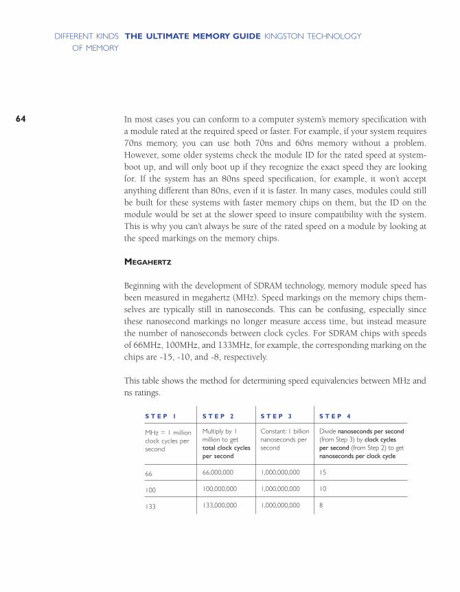
In most cases you can conform to a computer system’s memory specification witha module rated at the required speed or faster. For example, if your system requires70ns memory, you can use both 70ns and 60ns memory without a problem.However, some older systems check the module ID for the rated speed at system-boot up, and will only boot up if they recognize the exact speed they are lookingfor. If the system has an 80ns speed specification, for example, it won’t accept anything different than 80ns, even if it is faster. In many cases, modules could stillbe built for these systems with faster memory chips on them, but the ID on themodule would be set at the slower speed to insure compatibility with the system.This is why you can’t always be sure of the rated speed on a module by looking atthe speed markings on the memory chips.
MEGAHERTZ
Beginning with the development of SDRAM technology, memory module speed hasbeen measured in megahertz (MHz). Speed markings on the memory chips them-selves are typically still in nanoseconds. This can be confusing, especially sincethese nanosecond markings no longer measure access time, but instead measurethe number of nanoseconds between clock cycles. For SDRAM chips with speedsof 66MHz, 100MHz, and 133MHz, for example, the corresponding marking on thechips are -15, -10, and -8, respectively.
This table shows the method for determining speed equivalencies between MHz andns ratings.
64
THE ULTIMATE MEMORY GUIDE KINGSTON TECHNOLOGYDIFFERENT KINDS
OF MEMORY
S T E P 1
MHz = 1 millionclock cycles persecond
66
100
133
S T E P 2
Multiply by 1 million to gettotal clock cyclesper second
66,000,000
100,000,000
133,000,000
S T E P 3
Constant: 1 billionnanoseconds persecond
1,000,000,000
1,000,000,000
1,000,000,000
S T E P 4
Divide nanoseconds per second(from Step 3) by clock cycles per second (from Step 2) to getnanoseconds per clock cycle
15
10
8

65
THE ULTIMATE MEMORY GUIDE KINGSTON TECHNOLOGYDIFFERENT KINDS
OF MEMORY
nanoseconds per second 1,000,000,000ns nanoseconds____________________ = ______________ = __________clock cycles per second clock cycles clock cycle
As noted in a previous section, the speed of the processor and the speed of the memorybus are normally not the same. The speed of memory is limited by the speed of the memorybus, which is the slowest link in the process.
BYTES PER SECOND
Converting MHz to bytes per second can be confusing at first. The two most importantpieces of information you need to make the conversion is the speed (in MHz) and thewidth (in bits) of the bus.
Bus Width: If you have an 8-bit bus, then 8 bits, or 1 byte of information at a time cantravel on the bus. If you have a 64-bit bus, then 64-bits, or 8 bytes of information cantravel at a time.
Bus Speed: If the memory bus speed is 100MHz, this measures 100 million clockcycles per second. Typically, one packet of information can travel on each clockcycle. If the 100MHz bus is 1 byte wide, then data can travel at 100 megabytes persecond. Data travels on a 100MHz, 64-bit bus at 800 megabytes per second.
Rambus modules are sometimes measured in MHz and sometimes measured inmegabytes per second. One type of Rambus module runs on a 400MHz bus, butbecause Rambus modules can send two pieces of information per clock cycleinstead of one, the module is rated at 800MHz. This is sometimes referred to as PC-800. Because the Rambus bus width is 16-bit, or 2 bytes wide, data travels at1600MB per second, or 1.6GB per second. Using the same logic, PC-600 Rambustransfers data at 1.2 gigabytes per second.
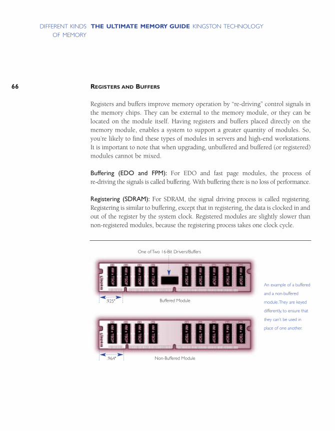
REGISTERS AND BUFFERS
Registers and buffers improve memory operation by “re-driving” control signals inthe memory chips. They can be external to the memory module, or they can belocated on the module itself. Having registers and buffers placed directly on thememory module, enables a system to support a greater quantity of modules. So,you’re likely to find these types of modules in servers and high-end workstations.It is important to note that when upgrading, unbuffered and buffered (or registered)modules cannot be mixed.
Buffering (EDO and FPM): For EDO and fast page modules, the process of re-driving the signals is called buffering. With buffering there is no loss of performance.
Registering (SDRAM): For SDRAM, the signal driving process is called registering.Registering is similar to buffering, except that in registering, the data is clocked in andout of the register by the system clock. Registered modules are slightly slower thannon-registered modules, because the registering process takes one clock cycle.
66
THE ULTIMATE MEMORY GUIDE KINGSTON TECHNOLOGYDIFFERENT KINDS
OF MEMORY
Non-Buffered Module
An example of a buffered
and a non-buffered
module.They are keyed
differently, to ensure that
they can’t be used in
place of one another.
Buffered Module
One of Two 16-Bit Drivers/Buffers
.925"
.964"

67
THE ULTIMATE MEMORY GUIDE KINGSTON TECHNOLOGYDIFFERENT KINDS
OF MEMORY
MULTIPLE-BANKED MODULES
A multiple-banked module allows more flexibility in type of chips used. Multiplebanking allows a memory designer to divide the module into banks, which meansit can appear to the computer system to be more than one module. This design is equivalent to the banks of memory sockets in a computer: the system accessesone bank of memory at a time, regardless of how many actual memory socketscomprise a bank.
TIN VERSUS GOLD
Memory modules are manufactured with either tin leads (connectors) or gold leads.Gold is a better conductor than tin. However, because tin is much less expensivethan gold, computer manufacturers began using tin sockets on system boards in theearly 1990s to reduce their costs. If you’re buying memory and you have a choice– that is, compatible modules come in both tin and gold – it’s best to match themetal of the module to the metal of the socket it will be going into. Matching metalscan help avoid corrosion.
Some people confuse the
terms “double-sided“ and
“dual-banked”. To clarify:
Double-sided is a physical
term meaning that chips
are arranged on two
sides of the memory
module. Dual-banked is
an electrical term meaning
that the module is divided
electrically into two
memory banks.
Kingston’s policy has
always been to match
metals, so Kingston part
numbers assigned to
each computer system
take the socket metal
into account.

REFRESH RATES
Refresh is the process of recharging, or re-energizing, the “memory cells” in a memory chip. Internally, computer memory is arranged as a matrix of memory cellsin rows and columns – like the squares on a checkerboard – with each columnbeing further divided by the I/O width of the memory chip. The entire organizationof rows and columns is called a DRAM array. DRAM is called “dynamic” RAMbecause it must be refreshed, or re-energized, thousands of times each second inorder to retain data. It has to be refreshed because its memory cells are designedaround tiny capacitors that store electrical charges. These capacitors work like verytiny batteries that lose their stored charges if they are not re-energized. Also, theprocess of reading data from the memory array drains these charges, so the memorycells must also be pre-charged before reading the data.
Cells are refreshed one row at a time (usually one row per refresh cycle).The termrefresh rate refers not to the time it takes to refresh the memory but to the totalnumber of rows that it takes to refresh the entire DRAM array. For example, a refreshrate of 2K indicates that it takes 2,048 rows to refresh the array; likewise, a 4K rateindicates 4,096 rows.
Normally, the system’s memory controller initiates the refresh operation. But somechips are able to “self refresh.” This means that the DRAM chip has its own refreshcircuitry and does not require intervention from the CPU or external memory controller. Self-refresh modules dramatically reduce power consumption and areoften used in portable computers.
CAS LATENCY
The term CAS latency refers to the number of clock cycles it takes before a columncan be addressed on the DRAM chip. Latency is a measure of delay, so a “CL2” CASlatency factor indicates a two-clock cycle delay, and a “CL3” latency factor indicatesa three-clock cycle delay. When SDRAM chips first came out, it was difficult to producechips with a CAS latency factor as low as CL2. And although some specificationscalled for CL2, many modules worked fine at a CAS latency factor of CL3.
68
THE ULTIMATE MEMORY GUIDE KINGSTON TECHNOLOGYDIFFERENT KINDS
OF MEMORY

69
THE ULTIMATE MEMORY GUIDE KINGSTON TECHNOLOGYDIFFERENT KINDS
OF MEMORY
HEAT SPREADERS AND HEAT SINKS
As memory components get faster, chips become more dense and more circuits getsqueezed onto smaller boards. Dissipation of excess heat becomes more of an issue.For several years now processors have incorporated fans. Newer memory moduledesigns use heat sinks or heat spreaders to maintain safe operating temperatures.
SERIAL PRESENCE DETECT (SPD) AND PARALLEL PRESENCE DETECT (PPD)
When a computer system boots up, it must “detect” the configuration of the memorymodules in order to run properly. Parallel Presence Detect is the traditional methodof relaying the required information by using a number of resistors. PPD is themethod SIMMs and some DIMMs use to identify themselves. Serial Presence Detectuses an EEPROM (Electrically Erasable Programmable Read-Only Memory) to storeinformation about the module.
NUMBER OF CLOCK LINES (2-CLOCK VERSUS 4-CLOCK)
SDRAM memory requires that clock lines run from the system clock to the memorymodule. “2-clock” means there are two clock lines running to the module, and “4-clock” means there are four clock lines running to the module. The first Inteldesigns were 2-clock because there were only eight chips on the module. Later, 4-clock designs were developed, which allowed for fewer chips per clock line, therebydecreasing the load on each line and enabling a quicker data interface.
VOLTAGES
Voltages on memory modules keep decreasing as memory cells in DRAMs get closertogether and heat becomes more of an issue. Most computer systems used to operateat a standard of 5 volts. Compact notebook computers were the first to use 3.3-voltchips. This was not only because of heat issues; since lower voltage chips use lesspower, using them made it easier to prolong battery life. Now most desktops arestandardized on 3.3-volt memory as well, but this is quickly being replaced by 2.5voltage chips as products continue to get smaller and components closer together.
An EPROM is a chip
that can be programmed
with various types of
information about the
memory module.This
information can include
the module capacity,
speed, type of memory,
and even the name of
the module manufacturer.
The CPU uses this
information when booting
up to understand what
kind of memory is in the
system and to adjust its
settings accordingly.
An EEPROM (electrically
erasable programmable
read-only memory)
chip (also known as an
E2PROM) differs from an
EPROM in that it does
not need to be removed
from the computer to be
modified. However, it
does have to be erased
and reprogrammed in its
entirety, not selectively.
It also has a limited
lifespan – that is, the
number of times it can be
reprogrammed is limited.

COMPOSITE VERSUS NON-COMPOSITE
Composite and non-composite were terms first used by Apple Computer to explainthe difference between modules of the same capacity that used a different numberof chips. To illustrate: when the industry is transitioning from one chip density toanother, there is normally a stage where you can build, for example, a memorymodule with 8 of the new density chips, or 32 of the old density chips. Applereferred to the module using the latest technology and fewer chips as “non-composite”, and the version using earlier technology and greater number ofchips as “composite”. Because 32 chips on a module can cause heat and spacingproblems, Apple would often advise customers to buy non-composite modules.
70
THE ULTIMATE MEMORY GUIDE KINGSTON TECHNOLOGYDIFFERENT KINDS
OF MEMORY

WHAT TO CONSIDER WHEN BUYING MEMORY
COMPATIBILITY
HOW TO READ A BANK SCHEMA
QUALITY
PRICING AND AVAILABILITY

73
THE ULTIMATE MEMORY GUIDE KINGSTON TECHNOLOGYWHAT TO CONSIDER
WHEN BUYING MEMORY
One of the quickest and easiest ways to identify the right memory modules andexpansion options for your computer is to use a memory configurator. Like someof the other major memory manufacturers, Kingston makes a memory configuratoravailable. You can access Kingston’s configurator through their home page atwww.kingston.com.
The most important thing to ensure when buying memory is compatibility withyour system. In addition, you’ll need to decide how much memory you need andbeyond that lie considerations of price, quality, availability, service, and warranty.This section helps you address these important decision factors and helps youanswer questions like these:
• How much memory do I need?• How much memory will my system recognize?• What kind of memory is compatible with my system?• How many sockets are open and how should I fill them?• How do I determine the quality of memory?• What should I know about memory prices?• What other issues should I consider?
COMPATIBILITY
As mentioned earlier, compatibility of memory components with your computersystem is arguably the most important factor to consider when upgrading memory.This section can get you started; it also makes frequent mention of the advantagesof using a memory configurator.
The amount of memory
you need depends on
how you plan to use
your computer system.
For example, memory
requirements for a desktop
computer vary according
to the operating system
and applications you’re
working with. Likewise,
memory requirements
for servers depend on
the operating system
and applications, in
addition to factors such
as the number of clients
and how memory-
intensive the interface is.
Kingston has established
general guidelines for
both desktop computer
and server use to help
you determine the right
amount of memory for
your situation. Refer to
the guidelines on pages 14
and 17 for more details.

WHAT KIND OF MEMORY IS COMPATIBLE WITH MY SYSTEM?
The easiest way to determine what type of memory goes with your system is to consult with your system documentation. If you need further assistance, consult amemory configurator available from many sources, including Kingston. Kingstonand other brand-name memory companies offer such a tool to help you find theright memory configuration for your system.
With Kingston’s configurator, you can search by five different criteria:
• System manufacturer/model• Computer model name• Memory module part number (Kingston, distributor, manufacturer)• Specification• Generic memory
To access Kingston’s Memory Configurator, go to: www.kingston.com
WHAT IF I CAN’T FIND MY SYSTEM IN A MEMORY CONFIGURATOR?
If you can’t find your system in the memory configuration programs, you can stillfind out what kind of memory you need by consulting the manual that came withyour system. In most cases, the manual will provide basic specifications such as thespeed and technology of the memory you need. This information is usually enoughto choose a module by specification. If you don’t feel you have enough information,you can call your system manufacturer or Kingston’s toll-free technical supportnumber for assistance.
HOW MANY SOCKETS DO I HAVE OPEN?
You may or may not have an idea what the inside of your computer looks like and howmemory is configured. You may have opened up your computer when you bought it tosee the configuration inside, or you may have looked at a configuration diagram in youruser’s manual. Even if you have no idea of the memory configuration of your system, you can use Kingston’s memory configuration tools to find out. For each system, the configuration includes a diagram, called a bank schema, which indicates how thememory sockets are arranged in your system and what the basic configuration rules are.The simple tutorial on the next page outlines how to use a bank schema diagram todetermine the number of sockets in your system and how to fill them.
74
THE ULTIMATE MEMORY GUIDE KINGSTON TECHNOLOGYWHAT TO CONSIDER
WHEN BUYING MEMORY
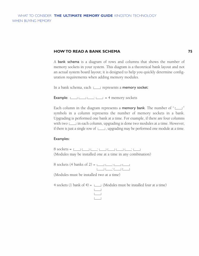
75
THE ULTIMATE MEMORY GUIDE KINGSTON TECHNOLOGYWHAT TO CONSIDER
WHEN BUYING MEMORY
HOW TO READ A BANK SCHEMA
A bank schema is a diagram of rows and columns that shows the number of memory sockets in your system. This diagram is a theoretical bank layout and notan actual system board layout; it is designed to help you quickly determine config-uration requirements when adding memory modules.
In a bank schema, each represents a memory socket:
Example: = 4 memory sockets
Each column in the diagram represents a memory bank. The number of “ ”symbols in a column represents the number of memory sockets in a bank.Upgrading is performed one bank at a time. For example, if there are four columnswith two in each column, upgrading is done two modules at a time. However,if there is just a single row of , upgrading may be performed one module at a time.
Examples:
8 sockets =(Modules may be installed one at a time in any combination)
8 sockets (4 banks of 2) =
(Modules must be installed two at a time)
4 sockets (1 bank of 4) = (Modules must be installed four at a time)

The standard memory (base amount that the system was shipped with) appears inthe diagram as either removable or non-removable.
Removable memory comes in the form of modules that fit into memory sockets,and, if desired, can be removed and replaced with modules of higher capacity.Removable memory is represented by a “ ” symbol with a number next to it:
4 that a 4MB module is in the first socket and that the second socket is empty.
Non-removable memory usually comes in the form of memory chips soldereddirectly onto the system board. It is represented in the bank schema in brackets:
indicates 4MB of non-removable memory soldered onto the board andtwo available memory sockets.
If your system is not included in the configurator, you may be able to find out howmany sockets are in the system and how many are filled by pressing the F1 key duringsystem startup. If your system supports this, a screen will appear that indicates howmany memory sockets are in the system, which ones are filled and which are open, andwhat capacity modules are in each socket. If pressing the F1 key during startup doesn’tproduce this result, check your computer’s system manual for more information.
As a last resort, you can open your computer and take a look at the sockets.(Important Note: Before removing the cover of your computer, refer to the computer’s system manual and warranty information for instructions and other relevant information.) If you do open the computer, you may be able to identify“bank labels” that indicate whether memory are installed in pairs. Bank numberingtypically begins with 0 instead of 1. So, if you have two banks, the first bank willbe labeled “bank 0”, and the second bank will be labeled “bank 1.”
76
THE ULTIMATE MEMORY GUIDE KINGSTON TECHNOLOGYWHAT TO CONSIDER
WHEN BUYING MEMORY
[4MB]
77
THE ULTIMATE MEMORY GUIDE KINGSTON TECHNOLOGYWHAT TO CONSIDER
WHEN BUYING MEMORY
HOW SHOULD I FILL THE SOCKETS?
In most cases, it’s best to plan your memory upgrade so you won’t have to removeand discard the memory that came with the computer. The best way to manage thisis to consider the memory configuration when you first buy the computer. Becauselower-capacity modules are less expensive and more readily available, system manufacturers may achieve a base configuration by filling more sockets with lower-capacity modules. By way of illustration, consider this scenario: a computer system with 64MB standard memory comes with either two (2) 32MB modules orone (1) 64MB module. In this case, the second configuration is the better choicebecause it leaves more room for growth and reduces the chance that you’ll have toremove and discard lower-capacity modules later. Unless you insist on the (1) 64MBmodule configuration, you may find yourself with only one socket left open forupgrading later.
Once you have purchased a computer and are planning your first upgrade, plan tobuy the highest-capacity module you think you may need, especially if you onlyhave one or two sockets available for upgrading. Keep in mind that, in general,minimum memory requirements for software applications double every 12 to 18months, so a memory configuration that’s considered large today will seem muchless so a year from now.
QUALITY
As with any type of product, memory can vary in the quality from one manufacturerto another. In general, the larger, more established brand name companies are moreconsistent in adhering to tight design specifications, using high-quality components,and establishing certified quality control processes for manufacturing and thoroughtesting. That’s not to say that lower-quality modules don’t work fine – they may bethe right solution, depending on how hard you work your system. In deciding thelevel of quality you require, consider the following:
1) If the memory you buy doesn’t perform well, will you be comfortable returningit for a replacement? Would you have the time to deal with removing the memory and waiting a couple of days to a week to get the situation resolved?
2) When memory is of low quality, you often experience intermittent problems,such as the computer “freezing” unexpectedly, or having frequent errors. Howoften do you save your work, and if you were to lose your work, how muchwould that cost you? If you use your computer to play games, read email, andsurf the Internet, such interruptions and losses may not be a big problem. But ifyou’re running a business, losing a few hours of work could be a serious matter.
3) The biggest risk with unreliable memory is data corruption: that is, some bitsof data may change or be read incorrectly. The result of data corruption couldbe as harmless as a syntax error in a document, or as potentially serious as a miscalculation in a spreadsheet. How important is the accuracy of the workyou do on your computer? Again, if you use your computer for gaming, writingletters, and the Internet, it may not be a problem. But if you’re managing yourfinances, you may want to do all you can to assure the reliability of your data.
4) Just like all products, the quality and durability you require depends on howyou use it. Computer applications that require a lot of memory usually workthe memory very hard. These applications often work better with memory thatexceeds the system’s speed and reliability specifications. If you’re working inmultimedia or using heavy number-crunching programs, the chance of alower-quality memory module failing is greater than if you’re only doing lightwork, such as simple word processing.
78
THE ULTIMATE MEMORY GUIDE KINGSTON TECHNOLOGYWHAT TO CONSIDER
WHEN BUYING MEMORY

79
THE ULTIMATE MEMORY GUIDE KINGSTON TECHNOLOGYWHAT TO CONSIDER
WHEN BUYING MEMORY
ASSESSING MEMORY QUALITY
Here are some important factors to keep in mind when assessing the quality of abrand of memory:
DESIGN
Designers of memory modules can follow strict specifications or take short cuts tosave money on components. In general, manufacturers who do in-house design havemore control over the quality of the module than those who farm this work out.
COMPONENTS
The quality of the DRAM chips, PC boards, and other components used on themodule are critical to the overall quality of the module. Premium memory chipscan cost up to 30% more than low-grade chips and high-quality PC boards costabout 50% more than lower quality alternatives.
ASSEMBLY
Many factors in module assembly can affect the overall quality of the module. Inaddition to proper handling of components, solder quality affects how reliablyinformation can travel from the chip to the module and back. The temperature andhumidity in the assembly and storage areas must be regulated to prevent warping,expansion, and contraction of components during assembly.
PROPER HANDLING
Electro-Static Discharge (ESD) is one of the most common causes of damage to amemory module. ESD damage can result from excessive and inappropriate han-dling. Memory modules should only be handled by workers who are properly“grounded” and modules should be properly packaged to protect against ESD during shipping.
TESTING
The more thoroughly memory has been tested before it is shipped, the less chance ofproblems during operation. In addition to standard production tests to ensure that themodules have been built correctly, memory can be tested for compatibility in the systems in which it will be used. The DRAM core can be tested for chip reliability, andmodules can be tested “at speed” to make sure they will work in high-use situations.Some companies perform testing at all levels, and some do less testing.
PRICING AND AVAILABILITY
This section contains information that helps make sense of the fluctuations that canoccur in the memory market.
THE DRAM CHIP MARKET
Memory modules are made with DRAM chips, which are manufactured in massquantities in enormous fabrication plants (often referred to as “fabs”). Fabs can takeup to two years to build and require substantial capital investment: approximately$3 billion per plant. These time and cost factors directly affect on the ability of thememory market to adjust quickly to fluctuations in supply and demand. Whendemand for memory chips increases, chip manufacturers typically do not respondimmediately because the investment required to add more capacity is substantialand may not pay off, especially if all the competitors are doing so at the same time.Therefore, the immediate effect is that prices rise as manufacturers assess whetherthe increase on demand is temporary or substantial enough to warrant investment.By the same token, when there is an oversupply situation in the market, chip manufacturers are willing to sustain losses for a long time while prices fall to belowbreakeven levels. This is because in many cases it costs more money to shut a plantdown than to continue to produce and sell chips at below cost. Also, the longer amanufacturer can hold on, the greater the chance of “being there” to reap therewards when competitors reduce capacity and the market turns around again.
80
THE ULTIMATE MEMORY GUIDE KINGSTON TECHNOLOGYWHAT TO CONSIDER
WHEN BUYING MEMORY
81
THE ULTIMATE MEMORY GUIDE KINGSTON TECHNOLOGYWHAT TO CONSIDER
WHEN BUYING MEMORY
WHY MEMORY PRICES FLUCTUATE
There are several factors that can affect memory prices. A few of these include:demand, DRAM manufacturing levels, inventory in the marketplace, time of theyear, new operating system releases, and computer sales. All these things can affectmemory prices at different times, either separately or simultaneously.
The most important thing to keep in mind when buying memory is that the priceof 256MB today will most likely be different than the price of 256MB next quarter.The best rule of thumb is to compare memory prices close to your time of purchase. When doing price comparisons, it’s more important to make sure you aremaking equivalent comparisons on module types than how the actual price per MBvaries over time. If there are shortages in the market it’s most important to be surethat what appears to be a “great deal” isn’t a “short-cut” module built from off-speccomponents. In an oversupply market, you’re much more likely to get a great price,but keep in mind that many manufacturers are losing money and may take shortcutson testing and other expensive production quality measures to compensate. Referto the quality section above for more details on this.

HOW TO INSTALL MEMORY
BEFORE YOU INSTALL
IMPORTANT THINGS TO KEEP IN MIND
INSTALLING THE MEMORY
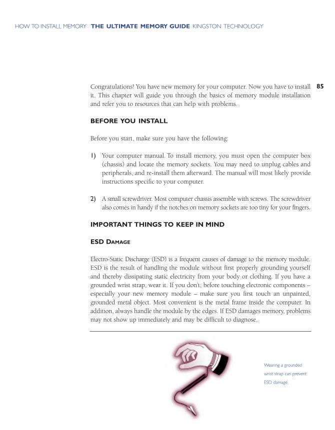
85
THE ULTIMATE MEMORY GUIDE KINGSTON TECHNOLOGYHOW TO INSTALL MEMORY
Congratulations! You have new memory for your computer. Now you have to installit. This chapter will guide you through the basics of memory module installationand refer you to resources that can help with problems.
BEFORE YOU INSTALL
Before you start, make sure you have the following:
1) Your computer manual. To install memory, you must open the computer box(chassis) and locate the memory sockets. You may need to unplug cables andperipherals, and re-install them afterward. The manual will most likely provideinstructions specific to your computer.
2) A small screwdriver. Most computer chassis assemble with screws. The screwdriveralso comes in handy if the notches on memory sockets are too tiny for your fingers.
IMPORTANT THINGS TO KEEP IN MIND
ESD DAMAGE
Electro-Static Discharge (ESD) is a frequent causes of damage to the memory module.ESD is the result of handling the module without first properly grounding yourselfand thereby dissipating static electricity from your body or clothing. If you have agrounded wrist strap, wear it. If you don’t, before touching electronic components –especially your new memory module – make sure you first touch an unpainted,grounded metal object. Most convenient is the metal frame inside the computer. Inaddition, always handle the module by the edges. If ESD damages memory, problemsmay not show up immediately and may be difficult to diagnose.
Wearing a grounded
wrist strap can prevent
ESD damage.

SWITCHING OFF THE POWER
Before opening the chassis, always power-off your computer and all attachedperipherals. Leaving power on can cause permanent electrical damage to your computer and its components.
INSTALLING THE MEMORY
The vast majority of computers today have memory sockets that accept the followingindustry-standard memory modules:
Desktops, Workstations and Servers
• 72-pin SIMM• 168-pin DIMM• 184-pin RIMM
Notebooks and Mobile Computers
• 144-pin SO DIMM
Although sockets may be in different places on different computers, installation isthe same. Consult the computer owner’s manual to find out whether the memorysits on an expansion card or on the motherboard, and whether internal computercomponents must be moved to gain access.
In the section below are installation instructions for the standard modules listedabove, followed by installation instructions for some of the more popular proprietarymemory modules. If the computer requires proprietary memory, or the instructionsbelow don’t seem to apply to your situation, phone Kingston Technology’s TechnicalSupport Group at (800) 435-0640.
86
THE ULTIMATE MEMORY GUIDE KINGSTON TECHNOLOGYHOW TO INSTALL MEMORY
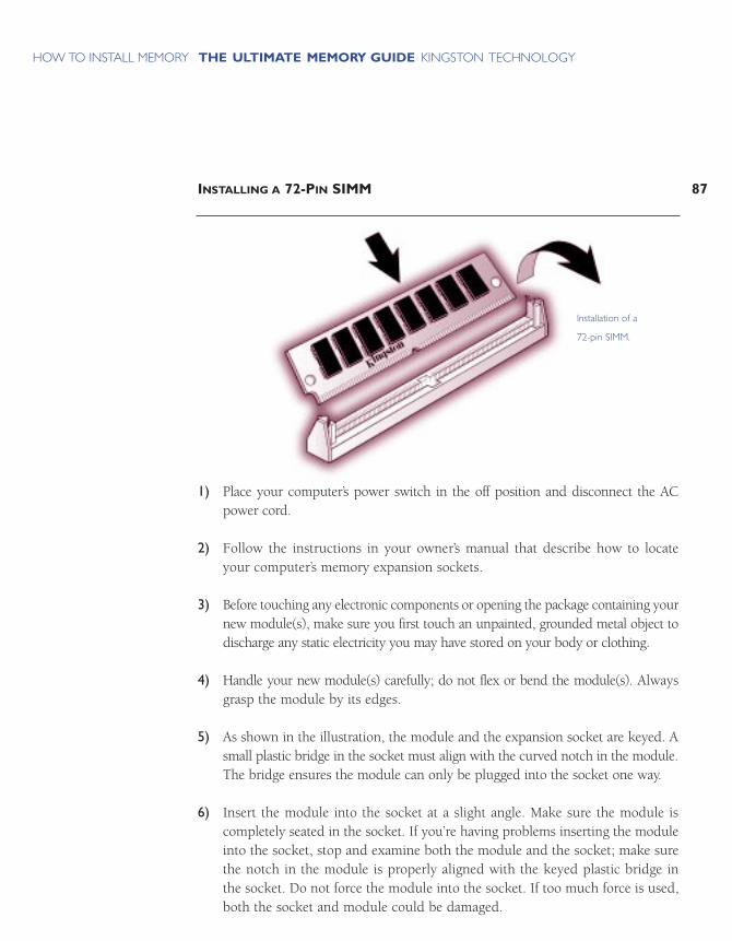
87
THE ULTIMATE MEMORY GUIDE KINGSTON TECHNOLOGYHOW TO INSTALL MEMORY
INSTALLING A 72-PIN SIMM
1) Place your computer’s power switch in the off position and disconnect the ACpower cord.
2) Follow the instructions in your owner’s manual that describe how to locateyour computer’s memory expansion sockets.
3) Before touching any electronic components or opening the package containing yournew module(s), make sure you first touch an unpainted, grounded metal object todischarge any static electricity you may have stored on your body or clothing.
4) Handle your new module(s) carefully; do not flex or bend the module(s). Alwaysgrasp the module by its edges.
5) As shown in the illustration, the module and the expansion socket are keyed. Asmall plastic bridge in the socket must align with the curved notch in the module.The bridge ensures the module can only be plugged into the socket one way.
6) Insert the module into the socket at a slight angle. Make sure the module iscompletely seated in the socket. If you’re having problems inserting the moduleinto the socket, stop and examine both the module and the socket; make surethe notch in the module is properly aligned with the keyed plastic bridge inthe socket. Do not force the module into the socket. If too much force is used,both the socket and module could be damaged.
Installation of a
72-pin SIMM.
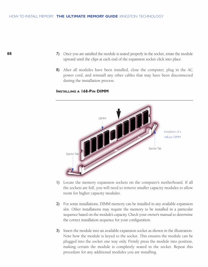
7) Once you are satisfied the module is seated properly in the socket, rotate the moduleupward until the clips at each end of the expansion socket click into place.
8) After all modules have been installed, close the computer, plug in the ACpower cord, and reinstall any other cables that may have been disconnectedduring the installation process.
INSTALLING A 168-PIN DIMM
1) Locate the memory expansion sockets on the computer’s motherboard. If allthe sockets are full, you will need to remove smaller capacity modules to allowroom for higher capacity modules.
2) For some installations, DIMM memory can be installed in any available expansionslot. Other installations may require the memory to be installed in a particularsequence based on the module’s capacity. Check your owner’s manual to determinethe correct installation sequence for your configuration.
3) Insert the module into an available expansion socket as shown in the illustration.Note how the module is keyed to the socket. This ensures the module can beplugged into the socket one way only. Firmly press the module into position,making certain the module is completely seated in the socket. Repeat this procedure for any additional modules you are installing.
88
THE ULTIMATE MEMORY GUIDE KINGSTON TECHNOLOGYHOW TO INSTALL MEMORY
Installation of a
168-pin DIMM.
DIMM
Ejector Tab
Ejector Tab
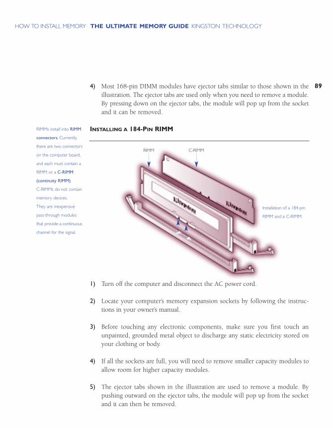
89
THE ULTIMATE MEMORY GUIDE KINGSTON TECHNOLOGYHOW TO INSTALL MEMORY
4) Most 168-pin DIMM modules have ejector tabs similar to those shown in theillustration. The ejector tabs are used only when you need to remove a module.By pressing down on the ejector tabs, the module will pop up from the socketand it can be removed.
INSTALLING A 184-PIN RIMM
1) Turn off the computer and disconnect the AC power cord.
2) Locate your computer’s memory expansion sockets by following the instruc-tions in your owner’s manual.
3) Before touching any electronic components, make sure you first touch anunpainted, grounded metal object to discharge any static electricity stored onyour clothing or body.
4) If all the sockets are full, you will need to remove smaller capacity modules toallow room for higher capacity modules.
5) The ejector tabs shown in the illustration are used to remove a module. Bypushing outward on the ejector tabs, the module will pop up from the socketand it can then be removed.
Installation of a 184-pin
RIMM and a C-RIMM.
RIMM C-RIMM
RIMMs install into RIMM
connectors. Currently,
there are two connectors
on the computer board,
and each must contain a
RIMM or a C-RIMM
(continuity RIMM).
C-RIMMs do not contain
memory devices.
They are inexpensive
pass-through modules
that provide a continuous
channel for the signal.
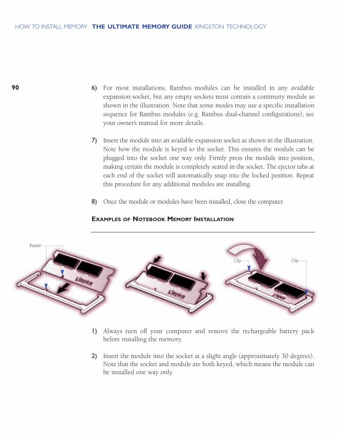
6) For most installations, Rambus modules can be installed in any availableexpansion socket, but any empty sockets must contain a continuity module asshown in the illustration. Note that some modes may use a specific installationsequence for Rambus modules (e.g. Rambus dual-channel configurations); seeyour owner’s manual for more details.
7) Insert the module into an available expansion socket as shown in the illustration.Note how the module is keyed to the socket. This ensures the module can beplugged into the socket one way only. Firmly press the module into position,making certain the module is completely seated in the socket. The ejector tabs ateach end of the socket will automatically snap into the locked position. Repeatthis procedure for any additional modules are installing.
8) Once the module or modules have been installed, close the computer.
EXAMPLES OF NOTEBOOK MEMORY INSTALLATION
1) Always turn off your computer and remove the rechargeable battery packbefore installing the memory.
2) Insert the module into the socket at a slight angle (approximately 30 degrees).Note that the socket and module are both keyed, which means the module canbe installed one way only.
90
THE ULTIMATE MEMORY GUIDE KINGSTON TECHNOLOGYHOW TO INSTALL MEMORY
Keyed
ClipClip
3) To seat the module into the socket, apply firm, even pressure to each end of themodule (see the arrows) until you feel it slip down into the socket. If you are having problems getting the module to seat properly, try rocking the module upand down slightly, while continuing to apply pressure. When properly seated,the contact fingers on the edge of the module will almost completely disappearinside the socket.
4) With the module properly seated in the socket, rotate the module downward,as indicated in the illustration. Continue pressing downward until the clips ateach end of the socket lock into position. With most sockets, you will hear adistinctive click, indicating the module is correctly locked into position.
91
THE ULTIMATE MEMORY GUIDE KINGSTON TECHNOLOGYHOW TO INSTALL MEMORY
Although more and
more notebooks accept
standard SO DIMM
memory modules, many
still require proprietary
modules having unique
form factors. No standard
dictates where the
memory should be
installed in the notebook.
Because notebooks differ
greatly in how memory
is installed, you should
consult your computer
manual for specific
instructions.This example
shows a typical 144-pin
SO DIM installation.

TROUBLESHOOTINGMEMORY PROBLEMS
COMMON MEMORY PROBLEMS
BASIC TROUBLESHOOTING
WHEN THE PROBLEM OCCURS
HANDLING SPECIFIC PROBLEMS
STILL NEED HELP?

COMMON MEMORY PROBLEMS
When you have a problem with memory, the cause is usually one of three things:
Improper Configuration: You have the wrong part for your computer or did not follow the configuration rules.
Improper Installation: The memory may not be seated correctly, a socket is bad, orthe socket may need cleaning.
Defective Hardware: The memory module itself is defective.
The fact that many computer problems manifest themselves as memory problemsmakes troubleshooting difficult. For example, a problem with the motherboard orsoftware may produce a memory error message.
This chapter is designed to help you figure out if you have a memory problem, andif so, what kind of problem it is, so you can get to a solution as quickly as possible.
BASIC TROUBLESHOOTING
The following basic steps apply to almost all situations:
1) Make sure you have the right memory part for your computer.At the manufacturer’s Web site you can look up the part number. Many memorymanufacturers have configurators, which indicate the compatibilities of yourmodule. If not, phone the memory manufacturer, consult your computer manual,or phone the computer manufacturer.
2) Confirm that you configured the memory correctly.Many computers require module installation in banks of equal-capacity modules. Some computers require the highest capacity module to be in thelowest labeled bank. Other computers require that all sockets be filled; stillothers require single-banked memory. These are only a few examples of special configuration requirements. If you have a name-brand computer, visitKingston’s Web site (www.kingston.com) or use our upgrade manual to look upconfiguration rules specific to your computer. You can also contact technical support for your memory or computer manufacturer.
95
THE ULTIMATE MEMORY GUIDE KINGSTON TECHNOLOGYTROUBLESHOOTING
MEMORY PROBLEMS
3) Re-install the module.Push the module firmly into the socket. In most cases you hear a click whenthe module is in position. To make sure you have a module all the way in thesocket, compare the height of the module to the height of other modules inneighboring sockets.
4) Swap modules.Remove the new memory and see whether the problem disappears. Remove theold memory, reinstall the new, and see whether the problem persists. Try the memory in different sockets. Swapping reveals whether the problem is a particularmemory module or socket, or whether two types of memory aren’t compatible.
5) Clean the socket and pins on the memory module.Use a soft cloth to wipe the pins on the module. Use a PC vacuum or compressedair to blow dust off the socket. Do NOT use solvent, which may corrode themetal or prevent the leads from making full contact. Flux Off is a cleaner used specifically for contacts. You can purchase it at electronics or computer equipment stores.
6) Update the BIOS.Computer manufacturers update BIOS information frequently and post revisionson their Web sites. Make sure you have the most recent BIOS for your computer.This applies especially when you have recently installed new software or you aresignificantly upgrading memory.
WHEN THE PROBLEM OCCURS
When the problem occurs is a clue as to the cause.
For example, your response to a memory error message depends on whether:
1) You have just bought a new computer.2) You have just installed new memory.3) You have just installed new software or a new operating system.4) You have just installed or removed hardware.5) Your computer has been running fine and you’ve made no other recent changes.
96
THE ULTIMATE MEMORY GUIDE KINGSTON TECHNOLOGYTROUBLESHOOTING
MEMORY PROBLEMS

97
THE ULTIMATE MEMORY GUIDE KINGSTON TECHNOLOGYTROUBLESHOOTING
MEMORY PROBLEMS
Here are rules to get started:
YOU’VE JUST BOUGHT A NEW COMPUTER
If you have just purchased a new computer and it is producing memory errors, theproblem could be related to anything, including a bad computer board. In this case,you need to troubleshoot the entire computer, including memory. Because the computer dealer will have configured memory and run system tests before shipping,they can best help.
YOU’VE JUST INSTALLED NEW MEMORY
If you have just installed new memory, the first possibility is that you installedincorrect parts. Double-check the part numbers. Confirm that you have configuredand installed the memory correctly.
YOU’VE INSTALLED NEW SOFTWARE OR OPERATING SYSTEM
Newer software or operating systems tend to push memory harder than older operatingsystems. Sometimes memory that worked fine prior to a software installationbegins producing errors once it runs memory-intensive software. New software alsohas bugs, and beta versions are notorious for producing memory errors. In thesecases, your first step should be to ensure you have the latest BIOS and servicepatches for your software. Otherwise contact the memory vendor. A technical support representative may have experience with other software incidents and canwalk you through more-detailed troubleshooting.
YOU’VE INSTALLED OR REMOVED HARDWARE
If you have just installed or removed hardware and suddenly receive memory errormessages, the first place to look is in the computer itself. A connection may havecome loose during the installation or the new hardware may be defective; in eithercase the errors are manifesting themselves as memory problems. Make sure youhave the latest drivers and firmware. Most hardware manufacturers will postupdates on their Web sites.

UNEXPECTED PROBLEMS
If your system has been running fine, but suddenly starts to produce memory errors,and crash or lock up frequently, the chance of a hardware failure is more likely, sinceconfiguration and installation problems show up as soon as the computer turns on.Sometimes you can get memory problems if your computer is overheating, if you arehaving a problem with your power supply, or if corrosion has developed betweenthe memory module and the socket, weakening the connection.
HANDLING SPECIFIC PROBLEMS
Here is a list of the most common ways the computer informs you of a memory problem.
1) The computer won’t boot, merely beeps.
2) The computer boots but doesn’t recognize all the installed memory.
3) The computer boots but the screen is blank.
4) The computer reports a memory error.a) Memory mismatch errorb) Memory parity interrupt at xxxxx c) Memory address error at xxxxxd) Memory failure at xxxxx, read xxxxx, expecting xxxxxe) Memory verify error at xxxxx
5) The computer has other problems caused by memory.a) The computer intermittently reports errors, crashes frequently,
or spontaneously reboots.b) Registry Errorsc) General-protection faults, page faults, and exception errors
6) The server system manager reports a memory error.
98
THE ULTIMATE MEMORY GUIDE KINGSTON TECHNOLOGYTROUBLESHOOTING
MEMORY PROBLEMS
99
THE ULTIMATE MEMORY GUIDE KINGSTON TECHNOLOGYTROUBLESHOOTING
MEMORY PROBLEMS
The following translations help you understand what the computer means when itgives you one of these signals.
1) Computer won’t boot, merely beeps.Every time the computer starts, it takes inventory of hardware. Inventory consists of the computer BIOS recognizing, acknowledging, and in some cases,assigning addresses to, the components in the computer. If the computer won’tboot, the CPU is unable to communicate with hardware. The cause can beimproper installation or failure of the BIOS to recognize hardware.
Follow basic troubleshooting, paying special attention to whether the memorymodule is completely installed and that you have the latest version of the BIOS.
2) Computer boots but doesn’t recognize all the installed memory.When the computer boots, a part of the process is counting memory. On somemachines the count appears on the screen and on others is masked. If thecount is masked, from the computer set-up menu see how much memory thecomputer thinks it has. If the computer counts to or lists a number less thanthe memory you installed, the computer hasn’t recognized all the memory.
Sometimes the computer will recognize only part of a module. This is almostalways due to using the wrong kind of memory. For example, if your computeraccepts only single-banked memory and you have installed dual-banked, thecomputer will read only half the memory on the module. Sometimes the computer will accept only modules containing memory chips with specificorganizations. For example, the VX chipset doesn’t work well with 64 Mbit chips.
In many computers the maximum amount of memory the computer can recognize is lower than the maximum amount you can physically install. Forexample, your computer may have three sockets, each of which can hold a128MB module. If you filled every socket with 128MB, you would have 384MBof memory. However, your computer may recognize a maximum of 256MB. Inmost cases you can avoid this problem by consulting your computer manual ora memory configuration Web site before purchasing memory. Or visit theKingston Web site.
3) The computer boots but the screen is blank.The most common reason for a blank screen is a dislodged card, memory not fully seated, or memory the computer doesn’t support. Confirm that thememory is installed properly and that other components in the computer werenot accidentally disconnected or dislodged while you installed memory.
Double-check that you have the right part number for the computer. If you havenonparity memory in a computer that requires error-checking memory, orSDRAM memory in a computer that supports only EDO, the screen may beblank at boot up.
4) The computer reports a memory error.Memory mismatch error: This is not actually an error. Some computers requireyou to tell them that it’s OK to have a new amount of memory. Use the set-upmenu to tell the computer. Follow the prompts, enter the new amount, selectSave, and exit.
Computer memory or address errors: All of the following errors, and thosesimilar to them, indicate that the computer has a problem with memory:
• Memory parity interrupt at xxxxx • Memory address error at xxxxx• Memory failure at xxxxx, read xxxxx, expecting xxxxx• Memory verification error at xxxxx
Typically the computer will perform a simple memory test as it boots. Thecomputer will write information to memory and read it back. If the computerdoesn’t get what it was expecting, then it will report an error and sometimesgive the address where the error occurred.
Such errors normally indicate a problem with a memory module but can sometimes indicate a defective motherboard or incompatibility between oldand new memory. To verify that the new memory is causing the problem,remove the new memory and see whether the problem goes away. Thenremove the old memory and install only the new memory. If the error persists,phone the memory manufacturer and ask for a replacement.
100
THE ULTIMATE MEMORY GUIDE KINGSTON TECHNOLOGYTROUBLESHOOTING
MEMORY PROBLEMS

101
THE ULTIMATE MEMORY GUIDE KINGSTON TECHNOLOGYTROUBLESHOOTING
MEMORY PROBLEMS
5) The computer has other problems caused by memory.The Computer Intermittently Reports Errors, Crashes Frequently, orSpontaneously Reboots: Because of the large number of causes, these problemsare difficult to diagnose. Possible causes are ESD (Electro-static Discharge),overheating, corrosion, or a faulty power supply. If you suspect ESD damage,contact the memory manufacturer and ask for a replacement. Before you installnew memory, see page 85 for information on how to prevent ESD. If you suspectcorrosion, clean the memory contacts and the sockets as explained on page 96.If you suspect the power supply, you will have to do overall computer troubleshooting with a focus on the power supply.
Registry Errors: Windows writes a large portion of the registry to RAM.Sometimes defective memory will cause registry errors. Windows reports a registry error and prompts you to restart and restore. If the prompts repeat,remove your newly installed memory and restart the computer. If the errorsdisappear, ask the memory manufacturer for replacement modules.
General-Protection Faults, Page Faults, and Exception Errors: The most commoncause is software. For example, one application may not have released thememory after quitting or occupies the same memory addresses as another. Inthese cases, rebooting should solve the problem. If the computer suddenly displays general-protection faults, exception errors, or page faults after youhave installed new memory, remove the new memory and see whether theerrors stop. If they occur only when the new memory is installed, contact thememory manufacturer for assistance.
6) The server system manager reports a memory error.Most servers ship with system managers that monitor component utilizationand test for abnormalities. Some of these system managers count soft errors inmemory. Soft errors have been corrected by ECC memory. If the rate of softerrors is higher than specifications, however, the system manager issues a pre-failure warning. This warning enables the network administrator to replacethe memory and prevent system downtime.

If the system manager on your server issues a pre-failure warning or othermemory error, ask your memory manufacturer for a replacement. If the systemmanager continues to issue errors after memory replacement, make sure youhave the latest BIOS, software service patches, and firmware. The chance ofreceiving two bad memory modules in a row is low. Contact the memory manufacturer for compatibility troubleshooting. Sometimes the server does notwork well with certain types of memory chips or certain memory designs.
STILL NEED HELP?
Most memory manufacturers have FAQ or Q-and-A sections on their Web sites. Thereare also troubleshooting areas on the Web site of the computer manufacturer. If youcan’t find anything online, phone technical support for the computer or memory man-ufacturer. The next section gives information about Kingston and how to reach us.
102
THE ULTIMATE MEMORY GUIDE KINGSTON TECHNOLOGYTROUBLESHOOTING
MEMORY PROBLEMS

MORE ABOUT KINGSTON
COMPANY OVERVIEW
HOW TO REACH KINGSTON
WHY KINGSTON?

105
THE ULTIMATE MEMORY GUIDE KINGSTON TECHNOLOGYMORE ABOUT KINGSTON
COMPANY OVERVIEW
Founded in 1987, Kingston Technology is the world’s largest independent manu-facturer of memory products. At the close of 1998, Kingston had sales in excess of$1.5 billion. Worldwide, the company presently staffs four manufacturing sites onfour continents and six international sales and marketing facilities.
Kingston manufactures memory products that consistently meet or exceed theindustry’s stringent standards, possessing both the skill and equipment necessaryto create the best modules in the marketplace.
The personal philosophy of company founders John Tu and David Sun, has beenpermanently imprinted into the corporate culture. From the company founders tothe employees and ultimately, to the consumer, a special “magic” is infused intoevery product. At Kingston, it is the people that make the difference.
The Kingston spirit reflects an individual commitment…
CORE VALUES
Respect for one another in our culturally diverse environment
Loyalty to our long-term partnerships
Flexibility and adaptability in responding to customer needs
Investing in our employees to continuously improve our most valuable resource
Having fun working in the company of friends
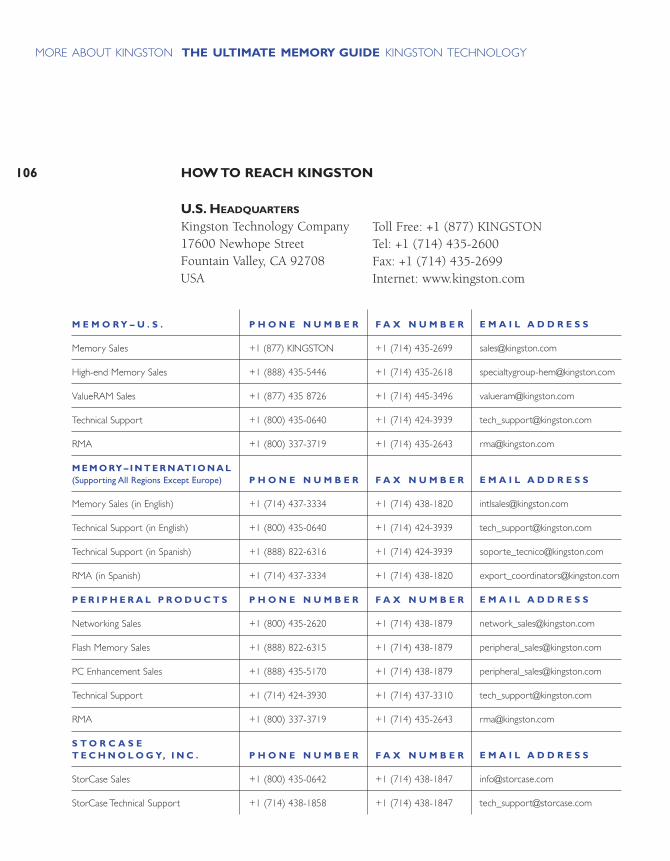
HOW TO REACH KINGSTON106
THE ULTIMATE MEMORY GUIDE KINGSTON TECHNOLOGYMORE ABOUT KINGSTON
M E M O R Y – U . S .
Memory Sales
High-end Memory Sales
ValueRAM Sales
Technical Support
RMA
M E M O RY – I N T E R N AT I O N A L(Supporting All Regions Except Europe)
Memory Sales (in English)
Technical Support (in English)
Technical Support (in Spanish)
RMA (in Spanish)
P E R I P H E R A L P R O D U C T S
Networking Sales
Flash Memory Sales
PC Enhancement Sales
Technical Support
RMA
S T O R C A S E T E C H N O L O G Y, I N C .
StorCase Sales
StorCase Technical Support
P H O N E N U M B E R
+1 (877) KINGSTON
+1 (888) 435-5446
+1 (877) 435 8726
+1 (800) 435-0640
+1 (800) 337-3719
P H O N E N U M B E R
+1 (714) 437-3334
+1 (800) 435-0640
+1 (888) 822-6316
+1 (714) 437-3334
P H O N E N U M B E R
+1 (800) 435-2620
+1 (888) 822-6315
+1 (888) 435-5170
+1 (714) 424-3930
+1 (800) 337-3719
P H O N E N U M B E R
+1 (800) 435-0642
+1 (714) 438-1858
F A X N U M B E R
+1 (714) 435-2699
+1 (714) 435-2618
+1 (714) 445-3496
+1 (714) 424-3939
+1 (714) 435-2643
F A X N U M B E R
+1 (714) 438-1820
+1 (714) 424-3939
+1 (714) 424-3939
+1 (714) 438-1820
F A X N U M B E R
+1 (714) 438-1879
+1 (714) 438-1879
+1 (714) 438-1879
+1 (714) 437-3310
+1 (714) 435-2643
F A X N U M B E R
+1 (714) 438-1847
+1 (714) 438-1847
E M A I L A D D R E S S
E M A I L A D D R E S S
E M A I L A D D R E S S
E M A I L A D D R E S S
U.S. HEADQUARTERS
Kingston Technology Company17600 Newhope StreetFountain Valley, CA 92708USA
Toll Free: +1 (877) KINGSTONTel: +1 (714) 435-2600Fax: +1 (714) 435-2699Internet: www.kingston.com
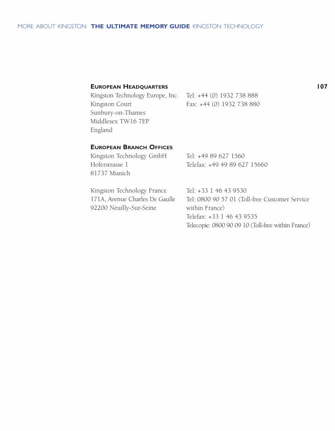
107
THE ULTIMATE MEMORY GUIDE KINGSTON TECHNOLOGYMORE ABOUT KINGSTON
EUROPEAN HEADQUARTERS
Kingston Technology Europe, Inc.Kingston CourtSunbury-on-ThamesMiddlesex TW16 7EPEngland
EUROPEAN BRANCH OFFICES
Kingston Technology GmbHHoferstrasse 181737 Munich
Kingston Technology France171A, Avenue Charles De Gaulle92200 Neuilly-Sur-Seine
Tel: +44 (0) 1932 738 888Fax: +44 (0) 1932 738 880
Tel: +49 89 627 1560Telefax: +49 49 89 627 15660
Tel: +33 1 46 43 9530Tel: 0800 90 57 01 (Toll-free Customer Servicewithin France)Telefax: +33 1 46 43 9535Telecopie: 0800 90 09 10 (Toll-free within France)

108
THE ULTIMATE MEMORY GUIDE KINGSTON TECHNOLOGYMORE ABOUT KINGSTON
WHY KINGSTON?
ISO 9001 CERTIFICATION
Kingston is ISO 9001 certified as part of a continuing global effort to assure customersthe highest quality service and products.
EXCEPTIONAL QUALITY
In addition to our ISO 9001 certification, we have established an extensive DCAT(Design, Components, Assembly, and Test) quality-control process to ensure totalproduct reliability.
PROVEN INDUSTRY LEADER
Kingston has been making memory modules since 1987.
100% PRODUCT TESTING
Kingston tests every memory module before shipping. Our customized test equipmentis so comprehensive that it can test every cell on every chip on every module-on a64MB module, that’s 512 million cells!
PREMIUM COMPONENTS
Kingston buys 100% of its memory chips from top-tier DRAM suppliers.
FREE TECHNICAL SUPPORT
Technical support professionals are available to answer your call 24 hours a day, 7 days a week at (800) 435-0640. Average wait time is less than 1 minute.
KINGSTON’S LIFETIME WARRANTY
With a lifetime warranty on all Kingston memory upgrades, network adapters, andprocessor upgrades, you have the most comprehensive warranty in the industry.
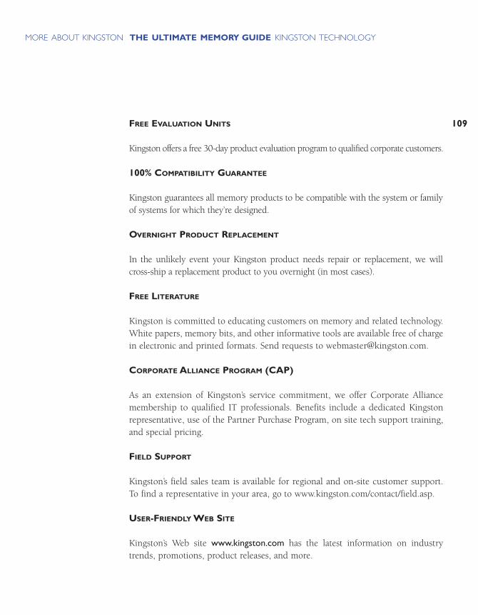
109
THE ULTIMATE MEMORY GUIDE KINGSTON TECHNOLOGYMORE ABOUT KINGSTON
FREE EVALUATION UNITS
Kingston offers a free 30-day product evaluation program to qualified corporate customers.
100% COMPATIBILITY GUARANTEE
Kingston guarantees all memory products to be compatible with the system or familyof systems for which they’re designed.
OVERNIGHT PRODUCT REPLACEMENT
In the unlikely event your Kingston product needs repair or replacement, we willcross-ship a replacement product to you overnight (in most cases).
FREE LITERATURE
Kingston is committed to educating customers on memory and related technology.White papers, memory bits, and other informative tools are available free of chargein electronic and printed formats. Send requests to [email protected].
CORPORATE ALLIANCE PROGRAM (CAP)
As an extension of Kingston’s service commitment, we offer Corporate Alliancemembership to qualified IT professionals. Benefits include a dedicated Kingstonrepresentative, use of the Partner Purchase Program, on site tech support training,and special pricing.
FIELD SUPPORT
Kingston’s field sales team is available for regional and on-site customer support. To find a representative in your area, go to www.kingston.com/contact/field.asp.
USER-FRIENDLY WEB SITE
Kingston’s Web site www.kingston.com has the latest information on industrytrends, promotions, product releases, and more.

THE GLOSSARY

113
THE ULTIMATE MEMORY GUIDE KINGSTON TECHNOLOGYTHE GLOSSARY
(AGP) – An Intel-developed interface that enables high-speed graphics. Graphicsdata move between the PC’s graphics controller and computer memory directly,instead of being cached in video memory.
The average time (in nanoseconds) for RAM to complete one access. Access time iscomposed of address setup time and latency (the time it takes to initiate a requestfor data and prepare access).
(American National Standards Institute) – The U.S. organization responsible for settinginformation technology standards.
(American Standard Code for Information Interchange) – A method of encoding textas binary values. The ASCII coding system contains 256 combinations of 7-bit or8-bit binary numbers to represent every possible keystroke.
(BSB) – The data path that runs between the CPU and L2 cache.
The amount of data moved on electronic lines, such as a bus, per second.Bandwidth is usually measured in bits per second, bytes per second, or cycles persecond (Hertz).
See memory bank.
A method of diagramming memory configurations. The bank schema consists ofrows and/or columns that represent memory sockets on a computer board. Rowsindicate independent sockets; columns represent banks.
The first generation of Rambus technology, first shipped in 1995.
(Ball Grid Array) – A chip package having solder balls on the underside for mounting.BGA allows for a reduction in die package size, better heat dissipation, and greatermodule densities.
A numbering system that uses combinations of 0 and 1 to represent data. Alsoknown as Base 2.
(Basic Input-Output System) – Startup routines that prepare the computer for operation.
Accelerated Graphics Port
Access Time
ANSI
ASCII
Backside Bus
Bandwidth
Bank
Bank Schema
Base Rambus
BGA
Binary
BIOS
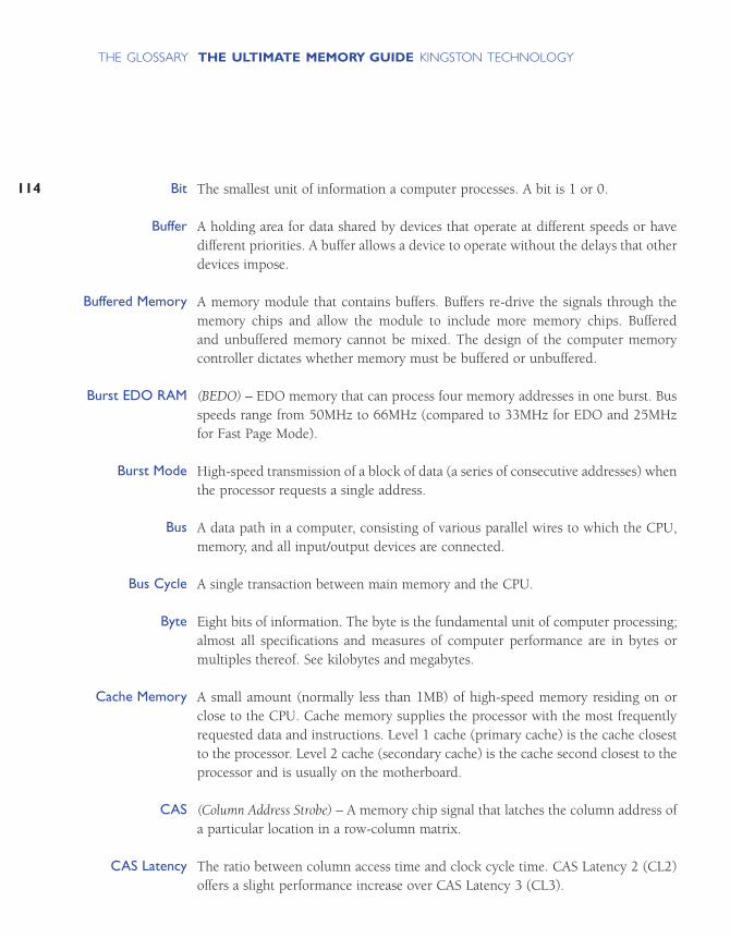
The smallest unit of information a computer processes. A bit is 1 or 0.
A holding area for data shared by devices that operate at different speeds or havedifferent priorities. A buffer allows a device to operate without the delays that otherdevices impose.
A memory module that contains buffers. Buffers re-drive the signals through thememory chips and allow the module to include more memory chips. Buffered and unbuffered memory cannot be mixed. The design of the computer memory controller dictates whether memory must be buffered or unbuffered.
(BEDO) – EDO memory that can process four memory addresses in one burst. Busspeeds range from 50MHz to 66MHz (compared to 33MHz for EDO and 25MHzfor Fast Page Mode).
High-speed transmission of a block of data (a series of consecutive addresses) whenthe processor requests a single address.
A data path in a computer, consisting of various parallel wires to which the CPU,memory, and all input/output devices are connected.
A single transaction between main memory and the CPU.
Eight bits of information. The byte is the fundamental unit of computer processing;almost all specifications and measures of computer performance are in bytes ormultiples thereof. See kilobytes and megabytes.
A small amount (normally less than 1MB) of high-speed memory residing on orclose to the CPU. Cache memory supplies the processor with the most frequentlyrequested data and instructions. Level 1 cache (primary cache) is the cache closestto the processor. Level 2 cache (secondary cache) is the cache second closest to theprocessor and is usually on the motherboard.
(Column Address Strobe) – A memory chip signal that latches the column address ofa particular location in a row-column matrix.
The ratio between column access time and clock cycle time. CAS Latency 2 (CL2)offers a slight performance increase over CAS Latency 3 (CL3).
114
THE ULTIMATE MEMORY GUIDE KINGSTON TECHNOLOGYTHE GLOSSARY
Bit
Buffer
Buffered Memory
Burst EDO RAM
Burst Mode
Bus
Bus Cycle
Byte
Cache Memory
CAS
CAS Latency

115
THE ULTIMATE MEMORY GUIDE KINGSTON TECHNOLOGYTHE GLOSSARY
(Cache-Coherent, Non-uniform Memory Access) – A flexible architecture that usesmodular, low-cost components and offers multidimensional scaling potential tohigh-end servers.
Microchips that support the CPU. The chipset usually contains several controllersthat govern how information travels between the processor and other components.
(CSP) – Thin chip packaging whereby electrical connections are typically through aball grid array. Chip-scale packaging is used in RDRAM and flash memory.
A small, lightweight form factor for removable storage cards. CompactFlash cardsare durable, operate at low voltages, and retain data when power is off. Usesinclude digital cameras, cell phones, printers, handheld computers, pagers, andaudio recorders.
An Apple Computer, Inc. term for a memory module that used an older technologyand contained more but lower-density chips.
The second generation of Rambus technology. Concurrent Rambus has been usedin graphics-based computers, digital TVs, and video game applications (such asNintendo 64 since 1997).
(C-RIMM) – A Direct Rambus memory module that does not contain memory chips. C-RIMM provides a continuous channel for the signal. In a Direct Rambus system, openconnectors must be populated with C-RIMMs.
(Central Processing Unit) – The computer chip that has primary responsibility forinterpreting commands and running programs. The CPU is also known as theprocessor or microprocessor.
A type of memory typically in laptop and notebook computers. Credit card memoryis the size of a credit card.
(Double Data Rate Synchronous Dynamic Random-Access Memory) – The latest gener-ation of SDRAM technology. Data is read on both the rising and the falling edge ofthe computer clock, thereby delivering twice the bandwidth of standard SDRAM.With DDR SDRAM, memory speed doubles without increasing the clock frequency.
ccNUMA
Chipset
Chip-Scale Package
CompactFlash
Composite
Concurrent Rambus
Continuity RIMM
CPU
Credit Card Memory
DDR SDRAM
(Dual In-line Memory Module) – A printed circuit board with gold contacts andmemory devices. A DIMM is similar to a SIMM, but with this primary difference:unlike the metal leads on either side of a SIMM, which are “tied together” electrically,the leads on either side of a DIMM are electrically independent.
Rambus technology’s third generation, which offers a completely new DRAM architecture for high-performance PCs. Data transfers at speeds up to 800MHz overa narrow 16-bit channel, compared to current SDRAM, which operates at 100MHzon a wide 64-bit bus.
(Dual In-line Package) – A DRAM component packaging. DIPs can be installed in socketsor permanently soldered into holes on the printed circuit board. The DIP packagewas extremely popular when memory was installed directly on the motherboard.
(Dynamic Random-Access Memory) – The most common form of RAM. DRAM canhold data for only a short time. To retain data, DRAM must be refreshed periodically.If the cell is not refreshed, the data disappear.
A memory module having two banks.
(DIB) – An Intel-developed bus architecture that offers greater bandwidth by havingtwo separate buses (frontside and backside) access the processor. Pentium II computers have DIBs.
(Error Correction Code) – A method of checking the integrity of data in DRAM. ECCprovides more elaborate error detection than parity; ECC can detect multiple-biterrors and can locate and correct single-bit errors.
(Extended Data-Out) – A DRAM technology that shortens the read cycle betweenmemory and CPU. On computers that support it, EDO memory allows a CPU toaccess memory 10 to 20 percent faster than comparable fast-page mode memory.
(Enhanced DRAM) – Enhanced Memory Systems, Inc. DRAM that contains a smallamount of SRAM.
(Electrically Erasable Programmable Read-Only Memory) – A memory chip thatretains data content after power has been removed. EEPROM can be erased andreprogrammed within the computer or externally.
116
THE ULTIMATE MEMORY GUIDE KINGSTON TECHNOLOGYTHE GLOSSARY
DIMM
Direct Rambus
DIP
DRAM
Dual-Banked
Dual Independent Bus
ECC
EDO
EDRAM
EEPROM

117
THE ULTIMATE MEMORY GUIDE KINGSTON TECHNOLOGYTHE GLOSSARY
(Extended ISA) – A bus architecture that extended the 16-bit ISA bus to 32 bits. EISAoperates at 8MHz and has a peak data transfer rate of 33MB per second. EISA wasintroduced in 1988 as an open alternative to IBM’s proprietary Micro Channel bus.
(ECC on SIMM) – An IBM data-integrity-checking technology that features ECCdata-integrity-checking on a SIMM.
(Erasable Programmable Read-Only Memory) – A programmable and reusable chipthat retains content until erasure under ultraviolet light. Special equipment erasesand reprograms EPROMs.
(Enhanced Synchronous DRAM) – A type of SDRAM developed by EnhancedMemory Systems, Inc. ESDRAM replaces expensive SRAM in embedded systemsand offers comparable speed with less power consumption and lower cost.
A type of data integrity checking whereby the parity bit checks for an even number of 1s.
(FCRAM) – FCRAM is a memory technology currently being developed by Toshibaand Fujitsu. FCRAM is not intended for PC main memory but will be used in specialty applications such as high-end servers, printers, and telecommunicationsswitching systems.
An early form of DRAM, fast-page mode’s advantage over previous page modememory technologies was faster access to data in the same row.
A solid-state, nonvolatile, rewritable memory that functions like a combination ofRAM and hard disk. Flash memory is durable, operates at low voltages, and retainsdata when power is off. Flash memory cards are used in digital cameras, cellphones, printers, handheld computers, pagers, and audio recorders.
The size, configuration, and other specifications used to describe hardware.Examples of memory form factors are: SIMM, DIMM, RIMM, 30-pin, 72-pin, and168-pin.
(FSB) – The data path that runs between the CPU and main memory (RAM).
Approximately 1 billion bits, or exactly 1 bit x 1,0243 (1,073,741,824) bits.
EISA
EOS
EPROM
ESDRAM
Even Parity
Fast-Cycle RAM
Fast-Page Mode
Flash Memory
Form Factor
Frontside Bus
Gigabit
Approximately 1 billion bytes, or exactly 1 byte x 1,0243 (1,073,741,824) bytes.
A sheath, usually aluminum, that covers an electronic device and dissipates heat.
A component, typically zinc alloy, that dissipates heat. CPUs require heat sinks.
(Integrated Circuit) – An electronic circuit on a semiconductor chip. The circuitincludes components and connectors. A semiconductor chip is usually molded ina plastic or ceramic case and has external connector pins.
Techniques for increasing memory speed. For example, with separate memorybanks for odd and even addresses, the next byte of memory can be accessed whilethe current byte refreshes.
(Joint Electron Device Engineering Council) – An Electronic Industries Alliance (EIA)body that sets semiconductor engineering standards.
Approximately one thousand bits, or exactly 1 bit x 210 (1,024) bits.
Approximately one thousand bytes, or exactly 1 byte x 210 (1,024) bytes.
(L1) – Also known as primary cache, L1 Cache is a small amount of high-speedmemory that resides on or very close to the processor. L1 Cache supplies theprocessor with the most frequently requested data and instructions.
(L2) – Also known as secondary cache, L2 Cache is a small amount of high-speedmemory close to the CPU and usually on the motherboard. L2 Cache supplies theprocessor with the most frequently requested data and instructions. Depending onthe motherboard, Level 2 cache may be upgraded.
See Motherboard.
Approximately one million bits, or exactly 1 bit x 1,0242 (1,048,576) bits.
Approximately one million bytes, or exactly 1 byte x 1,0242 (1,048,576) bytes.
A computer’s random-access memory. Memory temporarily holds data and instructionsfor the CPU. See RAM.
118
THE ULTIMATE MEMORY GUIDE KINGSTON TECHNOLOGYTHE GLOSSARY
Gigabyte
Heat Spreader
Heat Sink
IC
Interleaving
JEDEC
Kilobit
Kilobyte
Level 1 Cache
Level 2 Cache
Logic Board
Megabit
Megabyte
Memory

119
THE ULTIMATE MEMORY GUIDE KINGSTON TECHNOLOGYTHE GLOSSARY
A logical unit of memory in a computer, the size of which the CPU determines. Forexample, a 32-bit CPU requires memory banks that provide 32 bits of informationat a time. A bank can consist of one or more memory modules.
The bus that runs from the CPU to the memory expansion slots.
(MCH) – The interface between the processor, Accelerated Graphics Port, andRDRAM on motherboards that use Intel’s 820 or 840 chipsets.
(MTH) – The interface that allows SDRAM memory to be supported on a DirectRambus Channel for motherboards using Intel’s 820 chipset.
(µBGA) – Tessera, Inc. BGA chip packaging technique allows for a reduction in diepackage size, improved heat dissipation, and greater module densities.
Also known as the logic board, main board, or computer board, the motherboardis the computer’s main board and in most cases holds all CPU, memory, and I/Ofunctions or has expansion slots for them.
(ns) – One billionth of a second. Memory data access times are in nanoseconds. Forexample, memory access times for typical 30- and 72-pin SIMM modules rangefrom 60 to 100 nanoseconds.
Half of an 8-bit byte, or 4 bits.
An Apple Computer, Inc. term for a memory module that used a new technology andcontained fewer but higher-density chips. Non-composite modules were more reliableand more expensive than composite modules.
Data integrity checking in which the parity bit checks for an odd number of 1s.
Data integrity checking that adds a single bit to each byte of data. The parity bit isused to detect errors in the other 8 bits.
(Printed Circuit Board) – Generally flat, multi-layer boards made of fiberglass withelectrical traces. The surface and sublayers use copper traces to provide electricalconnections for chips and other components. Examples of PCBs include: mother-boards, SIMMs, and credit card memory.
Memory Bank
Memory Bus
Memory Controller Hub
Memory Translator Hub
Micro BGA
Motherboard
Nanosecond
Nibble
Non-Composite
Odd Parity
Parity
PCB

(PCMCIA: Personal Computer Memory Card International Association) – A standard thatallows interchangeability of various computing components on the same connector.The PCMCIA standard supports input-output devices, including memory,fax/modem, SCSI, and networking products.
(Peripheral Component Interconnect) – A peripheral bus that can send 32 or 64 bitsof data simultaneously. PCI offers plug-and-play capability.
Cache that reduces wait states and accelerates memory access by using pipeliningand bursting functions.
A technique in which memory loads the requested memory contents into a smallcache composed of SRAM, then immediately begins fetching the next memory contents. This creates a two-stage pipeline, where data is read from or written toSRAM in one stage, and data is read from or written to memory in the other stage.
Memory custom designed for a specific computer.
(Random-Access Memory) – A memory cell configuration that holds data for processing by a central processing unit (CPU). Random means the CPU can retrievedata from any address within RAM. See also Memory.
(1) Rambus, Inc. develops and licenses high-performance memory logic and circuit designtechnology and provides licensees with product design, layout, and testing information.(2) Direct Rambus is a high-speed memory technology that uses a narrow 16-bit bus(Rambus channel) to transmit data at speeds up to 800MHz. See Rambus Channel.
The data path of Rambus systems. Because of the narrow data width (two bytes),Rambus modules transfer data at up to 800MHz.
A memory chip signal that latches the row address of a particular location in a row-column matrix.
Refreshing maintains data stored in DRAM. The process of refreshing electrical cellson a DRAM component is similar to recharging batteries. Different DRAM componentsrequire different refresh methods.
The number of DRAM component rows that must be refreshed. Three commonrefresh rates are 2K, 4K and 8K.
120
THE ULTIMATE MEMORY GUIDE KINGSTON TECHNOLOGYTHE GLOSSARY
PC Card
PCI
Pipeline Burst Cache
Pipelining
Proprietary Memory
RAM
Rambus
Rambus Channel
RAS
Refresh
Refresh Rate

121
THE ULTIMATE MEMORY GUIDE KINGSTON TECHNOLOGYTHE GLOSSARY
SDRAM memory that contains registers directly on the module. The registers re-drive the signals through the memory chips and allow the module to be builtwith more memory chips. Registered and unbuffered memory cannot be mixed.The design of the computer memory controller dictates which type of memory thecomputer requires.
The trademarked name for a Direct Rambus memory module. A RIMM™ conforms tothe DIMM form factor and transfers data 16 bits at a time.
A Direct Rambus memory socket.
(Synchronous DRAM) – A DRAM technology that uses a clock to synchronize signalinput and output on a memory chip. The clock is coordinated with the CPU clockso the timing of the memory chips and the timing of the CPU are in synch.Synchronous DRAM saves time in executing commands and transmitting data,thereby increasing the overall performance of the computer. SDRAM allows theCPU to access memory approximately 25 percent faster than EDO memory.
A memory technology that enables DRAM to refresh on its own and independentof the CPU or external refresh circuitry. Self-Refresh technology is built into theDRAM chip itself and reduces power consumption dramatically. Notebook and laptopcomputers use this technology.
An EEPROM chip that contains information about size and speed, as well as otherspecifications and manufacturer information of a memory module.
(Synchronous Graphics Random-Access Memory) – Video memory that includes graphics-specific read/write features. SGRAM allows data to be retrieved and modified inblocks instead of individually. Blocking reduces the number of reads and writes thememory must perform and increases the performance of the graphics controller.
(Single In-line Memory Module) – A printed circuit board having memory devices andgold or tin/lead contacts. A SIMM plugs into a computer memory expansion socket.SIMMs offer two main advantages: ease of installation and minimal consumption ofboard surface. A vertically mounted SIMM requires only a fraction of the spacerequired by a horizontally mounted DRAM. A SIMM may have as few as 30 or as many as 200 pins. On a SIMM, the metal leads on either side of the board areelectrically tied together.
Registered Memory
RIMM™
RIMM Connector
SDRAM
Self-Refresh
Serial Presence Detect
SGRAM
SIMM

A motherboard component that holds a single SIMM.
A module that has only one bank or row.
(Synclink) – Although obsolete today, SLDRAM was a main memory technologydeveloped by a consortium of twelve DRAM manufacturers as an alternative toDirect Rambus technology.
An electronic device, similar in size to a credit card, that can store data and programswhile enhancing security. Applications include identification, mass transit, and banking.
(Small-Outline Dual In-line Memory Module) – An enhanced version of a standardDIMM. A 72-pin small-outline DIMM is about half the length of a 72-pin SIMM.
The trademarked name for a Direct Rambus memory module in notebook com-puters. SO-RIMM™s provide memory bandwidth comparable to desktop memoryconfigurations.
(Small-Outline J-lead) – A common form of surface-mounted DRAM packaging. AnSOJ is a rectangular package with J-shaped leads on the two long sides.
(SRAM) – A memory chip that requires power to retain content. SRAM is faster thanDRAM but more expensive and bulky. A typical use for SRAM is cache memory.
A data-holding device, such as a hard disk or CD-ROM.
Using part of the hard drive as memory when RAM is full. See Virtual Memory.
See Motherboard.
A technology that supports the backside bus in Direct Rambus systems.Informationis quickly pipelined in simultaneous packets. The memory controller reassemblesthe packets for frontside bus transfer and communication to the processor.
(Thin Small-Outline Package) – A DRAM package that uses gull-wing leads on bothsides. TSOP DRAM mounts directly on the surface of the printed circuit board. TheTSOP package is one-third the thickness of an SOJ. TSOP components commonlyoccur in small-outline DIMMs and credit card memory.
122
THE ULTIMATE MEMORY GUIDE KINGSTON TECHNOLOGYTHE GLOSSARY
SIMM Socket
Single-Banked
SLDRAM
SMART CARD
SO DIMM
SO-RIMM™
SOJ
Static RAM
Storage
Swapping
System Board
Transmission Line Technology
TSOP
123
THE ULTIMATE MEMORY GUIDE KINGSTON TECHNOLOGYTHE GLOSSARY
Memory that does not contain buffers or registers located on the module. Instead,these devices are located on the motherboard.
(VL-Bus) – A 32-bit local bus that runs between the CPU and peripheral devices atspeeds up to 40MHz.
(VCM) – VCM is a memory architecture developed by NEC. VCM allows differentblocks of memory–each with its own buffer–to interface separately with the controller. This way, system tasks can be assigned their own virtual channels.Information related to one function does not share buffer space with other tasksrunning simultaneously, thereby making overall operations much more efficient.
Simulated memory. When RAM is full, the computer swaps data to the hard diskand back as needed. See Swapping.
(Video Random-Access Memory) – Dual-ported (two separate data ports) memorytypically on a video or graphics card. One port is dedicated to the CRT and refreshesand updates the image. The second port is for the CPU or graphics controller andchanges the image data in memory.
An inactive period for the processor. Wait states result from the different clockspeeds of the processor and memory, the latter being typically slower.
(WRAM) – Samsung Electronics’ dual-ported (two separate data ports) memorytypically on a video or graphics card. WRAM has a 25% higher bandwidth thanVRAM but costs less.
Unbuffered Memory
VESA Local Bus
Virtual Channel Memory
Virtual Memory
VRAM
Wait State
Window Random AccessMemory

NOTES
ULTMEM.5 Revised 0500
Kingston Technology Company, 17600 Newhope Street, Fountain Valley, CA 92708 USA (714) 435-2600 Fax (714) 435-2699Kingston Technology Europe, Inc., Kingston Court, Sunbury-on-Thames, Middlesex TW16 7EP, England
© 2000 Kingston Technology Company, Inc. All rights reserved. All trademarks and registered trademarks are the property of their respective owners.
www.kingston.com


