
Thin ladder development
Status of ladder development for the thin ladderfest

Targets
• Aiming for 0.1 % X0
• Uniformity over full length of ladder• Compatibility with wire and bump
bonding• Provision for optical survey• Robust

The story so far…
• Have followed up three different approaches– Unsupported, ladder made purely from
thinned silicon and tensioned.– Fully supported, ladder placed on a self
supporting substrate.– Semi-supported, ladder placed on a
supporting substrate but tensioning still required.
Unsupported Ladder
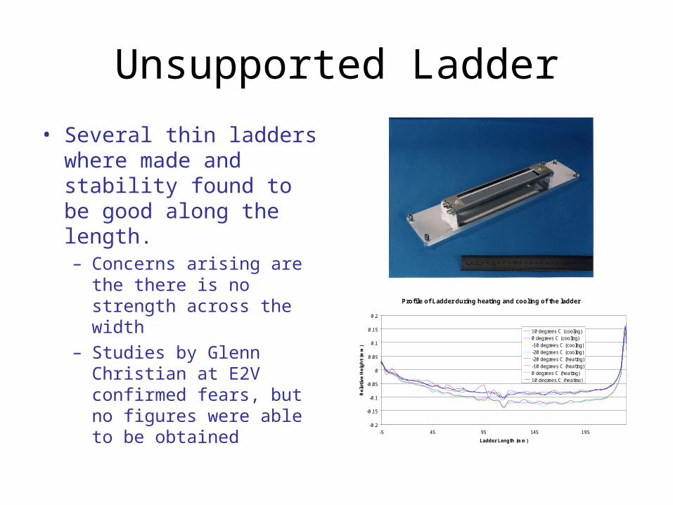
• Several thin ladders where made and stability found to be good along the length.– Concerns arising are
the there is no strength across the width
– Studies by Glenn Christian at E2V confirmed fears, but no figures were able to be obtained
Profile of Ladder during heating and cooling of the ladder
-0.2
-0.15
-0.1
-0.05
0
0.05
0.1
0.15
0.2
-5 45 95 145 195
Ladder Length (mm)
Rel
ativ
e H
eig
ht
(mm
)
10 degrees C (cooling)
0 degrees C (cooling)
-10 degrees C (cooling)
-20 degrees C (cooling)
-20 degrees C (heating)
-10 degrees C (heating)
0 degrees C (heating)
10 degrees C (heating)

Fully Supported ladders
• Shape of substrate would make it fairly non-uniform, at some angles particles would have to pass through a large amount of material
• Idea to rigidly fix thin silicon (20 microns thick) to a very rigid support– Support substrate could be hollowed out to
make it light weight, ie using a V or Ω beam

Semi-supported• Tensioned unsupported ladders have good
stability along length– Require a lightweight substrate to reinforce width.
• Pursed to methods with this in mind– tensioned substrate ladders and Sandwiched ladders
• Tensioned substrate ladders– Uses a gluing pattern similar to that used in SLD
experience• A stiff substrate is used such as beryllium or carbon fibre• The substrate is strong enough to resist curling across the
ladder caused by imbalances from the detector but not strong enough that it is self supporting along the length, hence requires tension.Tension
Silicon detector
Thin substrate Glue pillar
Now know beryllium has to large a difference of coefficient of expansion when compared to silicon, hence a thicker detector than preferred

• Sandwiched ladders– Makes the detector into a composite material made from
a core surrounded by thin silicon.• Core can be made from either a foam or a microstructure.• Structure strong enough along width, but would require
tensioning.
Microstructure sandwichTwo thin layers of silicon held apart buy thin silicon walls “grown” onto one of the layer of silicon
Silicon detector
Plain piece of silicon
Foam SandwichThin layers of silicon held apart by a foam, ie RVC foam
Silicon detector
Plain piece of silicon

Material profiles
Deflection vs X/X0 for a force of 0.1 Newtons
-4.00E-02
-3.50E-02
-3.00E-02
-2.50E-02
-2.00E-02
-1.50E-02
-1.00E-02
-5.00E-03
0.00E+00
0 0.05 0.1 0.15 0.2 0.25
X/X0 (%)
Def
lect
ion
(m
m)
Beryllium
Carbon fibre 1
Carbon fibre 2
Carbon fibre 3
Rohacell
SiC foam
Carbon foam
Graph below shows how a ladder of different thicknesses, if it is supported along one of it’s edges, deviates with a known force.

Table of comparisonMaterial X0 (cm) X/X0 (%) X/X0
Thickness(cm)
Thickness(um)
Thickness(m)
Elasti Modulus (Pa)
Force(N)
Length(m)
Width(m)
Deflection(m)
Deflection(mm) E*X0
3 (Nm)
Beryllium 35.4 0.05 0.0005 0.0177 177 0.000177 2.89E+11 0.1 0.025 0.25 -1.55999E-05 -1.56E-02 1.28E+10
Carbon fibre 28.2 0.05 0.0005 0.0141 141 0.000141 2.5E+11 0.1 0.025 0.25 -3.56732E-05 -3.57E-02 5.61E+09
Carbon fibre 2 28.2 0.05 0.0005 0.0141 141 0.000141 4.5E+11 0.1 0.025 0.25 -1.98185E-05 -1.98E-02 1.01E+10
Carbon fibre 3 28.2 0.05 0.0005 0.0141 141 0.000141 8.3E+11 0.1 0.025 0.25 -1.0745E-05 -1.07E-02 1.86E+10
Carbon foam 626.7 0.05 0.0005 0.3134 3134 0.0031335 4.50E+07 0.1 0.025 0.25 -1.80567E-05 -1.81E-02 1.11E+10
Rohacell 833 0.05 0.0005 0.4165 4165 0.004165 75000000 0.1 0.025 0.25 -4.61353E-06 -4.61E-03 4.34E+10
SiC 8.7 0.05 0.0005 0.0044 44 0.0000435 4.50E+11 0.1 0.025 0.25 -0.000674932 -6.75E-01 2.96E+08
SiC foam 108.7 0.05 0.0005 0.0544 544 0.0005435 2.76E+10 0.1 0.025 0.25 -5.64199E-06 -5.64E-03 3.54E+10
Silicon 9.4 0.05 0.0005 0.0047 47 0.000047 1.07E+11 0.1 0.025 0.25 -0.002250415 -2.25E+00 8.89E+07
Stainless Steel 1.6 0.05 0.0005 0.0008 8 0.000008 1.9E+11 0.1 0.025 0.25 -0.256990132 -2.57E+02 7.78E+05
Inputs are: Thickness of material and Elastic modulus


