
Dynamic Resource Allocation for CDMA-TDD Indoor Wireless Systems
Chae Y. Lee and Ki Won Sung
Dept. of Industrial Engineering, KAIST, 373-1, Kusung Dong, Taejon, Korea
Tel: +82-42-869-2916
FAX: +82-42-869-3110
Email: {chae, kwsung}@kaist.ac.kr
Abstract
Future wireless communication systems are expected to provide a broad range of multimedia services that
have a significant traffic asymmetry between uplink and downlink. The code division multiple access -
time division duplex (CDMA-TDD) system is a promising solution to cope with the problem of traffic
asymmetry. However, the TDD system is subject to inter-cell interference compared to frequency division
duplex (FDD) system. Since both uplink and downlink share the same frequency in TDD, uplink and
downlink may interfere each other especially when neighboring cells require different rates of traffic load.
Thus, the resource allocation among cells is an important issue in TDD. In this paper, the resource
allocation in the CDMA-TDD is formulated as a mixed integer programming (MIP) problem. A dynamic
resource allocation algorithm (DRAA) is provided that effectively solves the traffic asymmetry problem.
The MIP problem is also solved by a well-known branch and bound procedure. Both the crossed slot and
non-crossed slot allocation are examined and compared to the DRAA. Computational result shows that
proposed DRAA gives a good performance as the traffic asymmetry increases between the uplink and
downlink.
Keywords
CDMA-TDD, , dynamic resource allocation, mixed integer programming 0/ NEb
1

1. Introduction
Future wireless communication systems are expected to provide a broad range of multimedia services,
where the traffic asymmetry between uplink (UL) and downlink (DL) is significant. In the multimedia
traffic environment such as streaming or web services, the DL traffic will be the bottleneck of the system.
On the other hand, the uplink traffic may be bursty irregularly when mobiles use the file uploading
services. The dynamic change of the traffic asymmetry between UL and DL makes the resource allocation
of the future wireless system difficult. The code division multiple access system with time division duplex
mode (CDMA-TDD) is a promising solution to cope with the traffic asymmetry problem.
In the Third Generation Partnership Project (3GPP), CDMA-TDD mode has been proposed as one of
the standards for IMT-2000. The CDMA-TDD mode of 3GPP, named UTRA-TDD, is based on TD-
CDMA technology, which is a mixture of TDMA and CDMA [1, 2, 3, 4]. The resource of TD-CDMA is
divided in both time and code domain. The 10 ms frame consists of 15 time slots, each of which supports
parallel orthogonal spreading codes up to spreading factor of 16. Each time slot can be allocated to UL or
DL in a cell. Thus, the resources required for the asymmetric UL and DL traffic can be easily controlled
by the number of UL and DL slots in a frame. More detailed review of TD-CDMA can be found in [5, 6].
The resource allocation in the UMTS version of the CDMA-TDD system is divided into two parts:
slow dynamic channel allocation (DCA) and fast DCA [7]. Slow DCA is responsible for the allocation of
resources to cells. The slow DCA is typically operated at the radio network controller (RNC). The RNC
determines whether a time slot is used for UL or DL in each cell. Any specific timeslot within the TDD
frame is available for either the UL or DL transmission. However, an interference constraint should be
satisfied when the slow DCA is employed. On the contrary, the fast DCA reallocates resources to bearer
services in a cell. The fast DCA algorithms that can be operated at the BSs are investigated in [8, 9, 10,
11]. Most of algorithms determine the priority of each time slot when a bearer service requires resource in
the cell. Note that the fast DCA algorithm averages the interference levels of each slot so that none of the
slot may suffer from the excessive interference. In this paper, we are interested in the slow DCA
algorithm that reflects the dynamic change of traffic loads in the two-cell model. The proposed slow DCA
algorithm may well be a complement to any fast DCA algorithm. As an example, the RNC periodically
performs the slow DCA according to the estimated UL and DL traffic at each cell. Based on the slow
DCA, each BS then reallocates the resources to bearer services.
2

The number of UL and DL slots in each cell is decided in the slow DCA to resolve the asymmetric
traffic. However, the control of the UL and DL traffic in the CDMA-TDD brings about the inter-cell
interference problem compared to the traditional frequency division duplex (FDD) system. Since both UL
and DL share the same frequency band in the CDMA-TDD, the UL and DL transmission may interfere
each other especially when a time slot is used as an UL slot in a cell and a DL slot in an adjacent cell. It is
called as the crossed slot problem [12]. An efficient way of preventing serious interference problem in the
crossed slot is to divide the area of a cell into two regions. At the crossed slot, the transmission of mobiles
in the outer region is prohibited because these mobiles may cause severe interferences to mobiles in an
adjacent cell. The region division scheme is proposed in [12] and the performance is investigated in [13,
14] by the simulation studies
The crossed slot in the CDMA-TDD can resolve the traffic asymmetry between cells, however it may
cause serious interference problem as discussed above. Thus, whether to allow the crossed slot or not is
an important problem in the resource allocation of the CDMA-TDD system. Yomo and Hara [15] argue
that timeslots allocated to the UL or DL in a cell are preferred to be used in the same manner in other cells
to minimize the inter-cell interference. Non-crossed slot resource allocation algorithms are also proposed
in [8, 16]. However, Haas and McLaughlin [17] show a case where the capacity of the crossed slot
allocation is higher than that of the non-crossed slot allocation. The argument of [17] coincides with the
computational result by Jeon and Jeong [12] in which the system capacity of crossed and non-crossed slot
allocation is compared in two-cell model. In this paper, we propose a resource allocation algorithm that
efficiently employs the crossed slot depending on the traffic asymmetry between UL and DL.
The objective of the dynamic resource allocation in this paper is twofold. First, we need to satisfy the
traffic load in each cell. Secondly, in addition to the traffic load, extra capacity is considered to protect
unexpected bearer services in each cell. The resource allocation is formulated as a mixed integer
programming (MIP) problem. A dynamic resource allocation algorithm (DRAA) is proposed, which is
based on the maximum capacity at each time slot depending on the type of slot in the two cells. Then, the
performance of proposed DRAA is compared with the solutions by the crossed slot and the non-crossed
allocation.
The remainder of this paper is organized as follows. In Section 2, the system model and the problem is
explained. The dynamic resource allocation problem is formulated as a mixed integer programming and
the interference requirement of the system is analyzed. A dynamic resource allocation algorithm (DRAA)
3
is proposed in Section 3. Then, the performance of the proposed DRAA is demonstrated in Section 4. The
performance is compared with the crossed slot and non-crossed slot allocation procedures. Finally, the
conclusion is presented in Section 5.
2. System Model and Problem Description
In the 3GPP, different service needs are supported by a combination of FDD and TDD. The FDD is
intended for macro cell environment, while TDD is advantageous for micro and pico cells. The TDD is
particularly well suited for environments with high traffic density, indoor coverage, and highly
asymmetric traffic [5]. For the simplicity of the analysis, we assume a two-cell model as considered in [12,
14]. The two-cell model is not uncommon when we consider overlaid CDMA-TDD system on FDD to
cover the inbuilding area with high traffic intensity. When there exists multiple cells in a building, the
locally centralized system can be operated. Cells in the system are partitioned into local clusters such that
each cluster covers a number of cells [18]. The inter-cluster resources are allocated in a distributed
manner, while the intra-cluster resources are controlled by a centralized allocation algorithm.
In CDMA-TDD system, the resource consists of codes and timeslots. The basic resource unit (RU) for
the channel allocation is one code/timeslot/(frequency) [7]. Single frequency allocation is considered in
this paper. The data rate of an RU is assumed fixed and multi-rate services, if necessary, can be achieved
by the code and time pooling of multiple RUs. The UL (DL) capacity of a cell is defined as the number of
RUs allocated to the UL (DL) in a frame.
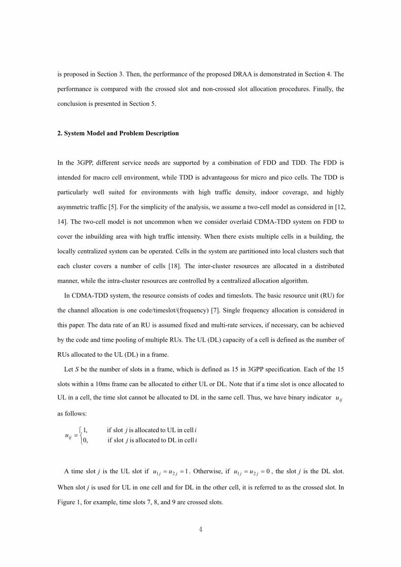
Let S be the number of slots in a frame, which is defined as 15 in 3GPP specification. Each of the 15
slots within a 10ms frame can be allocated to either UL or DL. Note that if a time slot is once allocated to
UL in a cell, the time slot cannot be allocated to DL in the same cell. Thus, we have binary indicator
as follows:
iju
=ijij
uij cellin DL toallocated is slot if ,0 cellin UL toallocated is slot if ,1
A time slot j is the UL slot if . Otherwise, if , the slot j is the DL slot.
When slot j is used for UL in one cell and for DL in the other cell, it is referred to as the crossed slot. In
Figure 1, for example, time slots 7, 8, and 9 are crossed slots.
121 == jj uu 021 == jj uu
4
Let be the number of RUs allocated to slot j in cell i. Also, let and respectively be the
UL and DL capacity of cell i. Since the capacity of a cell is defined as the number of RUs allocated in a
frame, and is expressed as
ijN
uiC
uiC d
iC
diC
∑=
=S
kikik
ui NuC
1
(1)
∑=
−=S
kikik
di NuC
1
)1( (2)
Let and be respectively the UL and DL traffic load by the ongoing bearer services in cell i.
Then, the residual capacities of cell i in the UL and DL are defined as C and ,
respectively.
uiT d
iT
ui
ui T− d
idi TC −
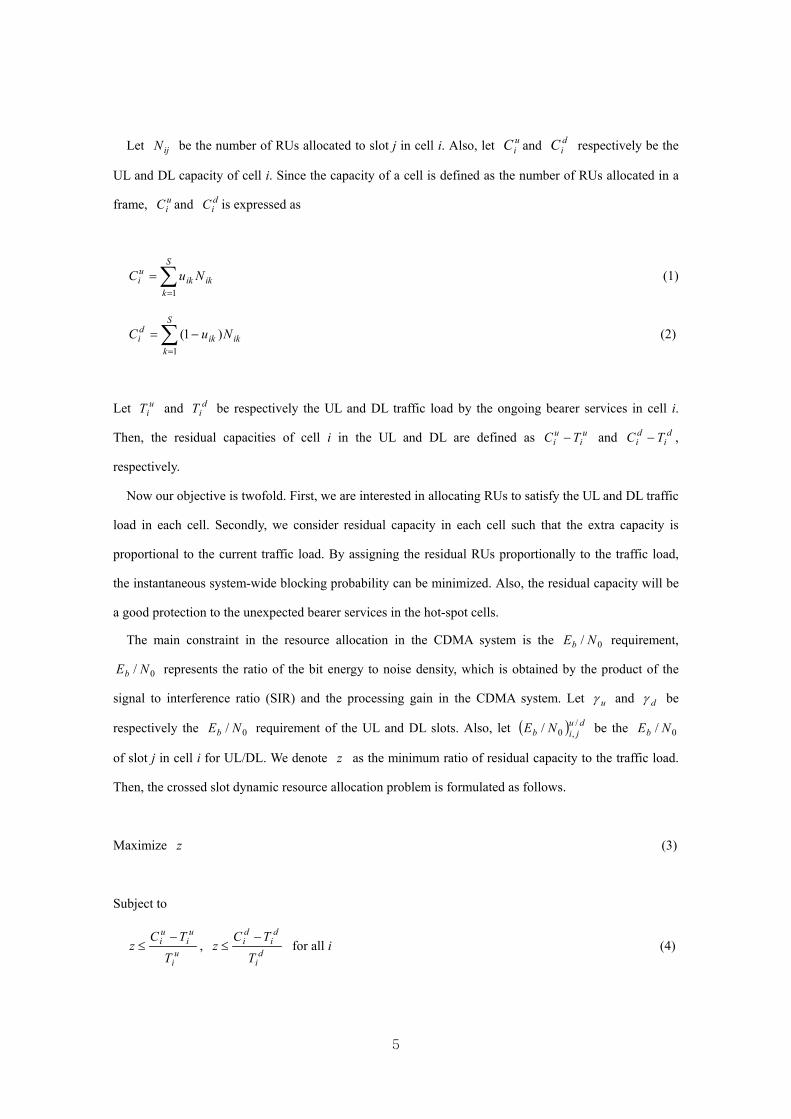
Now our objective is twofold. First, we are interested in allocating RUs to satisfy the UL and DL traffic
load in each cell. Secondly, we consider residual capacity in each cell such that the extra capacity is
proportional to the current traffic load. By assigning the residual RUs proportionally to the traffic load,
the instantaneous system-wide blocking probability can be minimized. Also, the residual capacity will be
a good protection to the unexpected bearer services in the hot-spot cells.
The main constraint in the resource allocation in the CDMA system is the requirement,
represents the ratio of the bit energy to noise density, which is obtained by the product of the
signal to interference ratio (SIR) and the processing gain in the CDMA system. Let
0/ NEb
u
0/ NEb
γ and dγ be
respectively the requirement of the UL and DL slots. Also, let 0/ NEb ( ) duji/
,0b NE / be the
of slot j in cell i for UL/DL. We denote
0N/Eb
z as the minimum ratio of residual capacity to the traffic load.
Then, the crossed slot dynamic resource allocation problem is formulated as follows.
Maximize z (3)
Subject to
ui
ui
ui
TTC
z−
≤ , d
i
di
di
TTC
z−
≤ for all i (4)
5

uij
u
ji
bij u
NE
u γ≥
,0, dij
d
ji
bij u
NE
u γ)1()1(,0
−≥
− for all i, j (5)
1≤iju for all i, j (6)
iju and are non-negative integer (7) ijN
Note that for the non-crossed slot allocation, the following constraint is added, where each slot is used
either UL or DL in the two cells.
jj uu 21 = for all j (8)
In the above formulation, the of the constraint (5) is dependent on the channel model and the
result of capacity analysis of the CDMA-TDD system. In this paper, we apply the capacity analysis given
in [12].
0/ NEb
When a slot is used as the crossed slot, a transmitting mobile in the UL cell may cause a significant
interference to a receiving mobile in the DL cell in the worst case, where two mobiles are located close to
each other near to the cell boundary as in Figure 2. To prevent the significant interference problem,
mobiles that use the crossed slot as the UL transmission is restricted within the inner circle [12, 13, 14,
19] that has the radius of r , where the radius of the cell is given as . D
For the analysis of the , let be the received signal power at a BS for an RU in UL. Also,
let be the received signal power at an MS for an RU in DL. By assuming the perfect power control,
a BS receives the same per each RU from all UL mobiles. Similarly, MSs also have the same
per each RU for all DL services.
0/ NEb
R
RP
RQ
P RQ
Let us denote as the transmission power of an MS that is located in the boundary of inner circle,
and as the transmission power of a BS to the MS that is located in the boundary of a cell. Then by
ignoring the fading effect, we have and Q , where is the path loss exponent.
Note in cellular systems, is much greater than .
TP
TQ
Tn
R PrP −= Tn
R QD−=
T
n
TQ P
Now, is determined by the amount of the received signal power and the interference power,
and the interference power is proportional to the number of allocated RUs in each cell. For a specific time
slot, three interference situations are possible: a time slot is used as a crossed slot, UL slot, or DL slot.
From [12], the in each case is expressed as follows. The background noise is ignored.
0/ NEb
E 0/ Nb
6

Case 1: A time slot is used as a crossed slot
Let and be the spreading bandwidth and data rate of an RU, respectively. Without loss of
generality, we assume slot j is used for UL in cell 1 and for DL in cell 2. Then, the BS in cell 1 receives
interference from the BS in cell 2. The distance of two BSs is . Thus,
W R
D2
uT
njRj
Ru
j
b
QDNPNP
SRW
NE
γ≥+−
=
−)2()1( 2110
(9)
In (9), represents the processing gain of an RU in slot j. SRW /
In the DL cell, each MS experiences different other cell interference due to the different location of the
MSs. Thus, of cell 2 is derived for a mobile located in the worst case position, i.e., the cell
boundary. For the target mobile, the other cell interference comes from mobiles in the cell 1. Since the
locations of interfering mobiles are different, the mobiles in the cell 1 are assumed to be uniformly
located within the inner circle of the cell. Then of cell 2 is given by
0/ NEb
0/ NEb
dtjRj
Rd
j
b
PINQNQ
SRW
NE
γ≥+−
=
1220 )1( (10)
In the equation tPI
)(aI
is the expected interference power from a mobile located at arbitrary position of cell
1. By denoting be the interference from a mobile at position and be the probability that
the mobile is located at position . Then,
a )(ap
a tPI is obtained by , where ∫ ap()A
da)aI ( A is the area of
the inner region of cell 1. Detailed analysis on the expected interference is given in [12].
Case 2: A time slot is used as an UL slot
Let ζ be the ratio of the interference from adjacent UL cell to that from the home cell [12]. Then, the
of cell 1 is given by 0/ NEb
uRjRj
Ru
j
b
PNPNP
SRW
NE
γζ
≥+−
=
2110 )1( (11)
7

0/ NEb of cell 2 is obtained by just substituting the cell index in the above equation. 06.0=ζ is
assumed in this paper.
Case 3: A time slot is used as a DL slot
A target mobile is assumed to be located in the cell boundary as in Case 1. Then,
dT
njRj
Rd
j
b
QDNQNQ
SRW
NE
γ≥+−
=
−
2110 )1( (12)
0/ NEb of cell 2 is derived in the same way.
From the above analysis, it is clear that the constraint (5) is nonlinear. Note that the
constraint (4) is also nonlinear. Since the problem with the nonlinear constraint requires a complex
nonlinear optimization procedure, we convert the two constraints into linear which is relatively easy to
solve. The linear conversion of constraints is given in the Appendix. Now, with the linear conversion the
crossed slot dynamic resource allocation given in (3) ~ (7) becomes a mixed integer programming (MIP)
problem.
0/ NEb
Note that the MIP version of the dynamic resource allocation problem requires too much computational
effort to obtain the optimal solutions. As the problem size increases, the MIP could not be solved
effectively by the conventional branch and bound technique [20] using the ILOG CPLEX 7.0
optimization software [21]. In problems with high traffic load and link asymmetry, the branch and bound
procedure failed to find the optimal solutions even with three hours of running time. Thus, to tackle the
dynamically changing traffic load in each cell, we provide a dynamic resource allocation algorithm as a
promising solution procedure for real-world problems.
3. Dynamic Resource Allocation Algorithm
To satisfy the asymmetric UL and DL traffic in each cell, we need to determine the number of UL, DL,
and crossed slots in the system. We also need to determine the number of RUs for each slot. In our
resource allocation, the crossed slot plays an important role in resolving the traffic asymmetry problem.
As the UL/DL asymmetry increases, the number of crossed slots increases.
8
The determination of the number of RUs allocated for each slot in each cell is flexible in CDMA due to
the soft capacity. The capacity of a cell is dependent on the amount of the resources allocated to the
adjacent cell. Thus we can assign more resources in a cell by decreasing the number of RUs of the
adjacent cell.
In this section, we first examine the number of RUs for each type of slot in each cell. Then the
determination of the number of UL, DL, and crossed slots in a frame will be considered. To determine the
number of RUs for each slot, we focus on the capacity constraints investigated in the previous section.
The capacity of a specific time slot is shown in Figure 3, 4, and 5 from equations (9) ~ (12). The
parameters used for the analysis are given in Table 1. From Figure 3, it is clear that the system
capacity of a crossed slot is maximized at the extreme point where the two constraints are crossing.
The same is true in Figure 4. The capacity is maximized at when the time slot is used for UL slot in
each cell. However, when the time slot is used for DL slot, the maximum capacity can be obtained at
any point on the constraint in Figure 5. Thus, the number of RUs at each slot is determined at the extreme
points and respectively when the slot is used as crossed and UL slot. When the slot is used as a
DL slot, any point on the constraint in Figure 5 can be selected.
0/ NEb
cP
uP
dP
cP uP
To determine the maximum capacity in each case, let us assume without loss of generality,
then it is clear that the crossed slot is used for DL in cell 1, and for UL in cell 2. Also, let us define the
following notations.
dd CC 21 ≥
uijx :number of RUs allocated to slot j in cell i at the point if slot j is the UL slot uP
dijx : number of RUs allocated to slot j in cell i at the point if slot j is the DL slot dP
dcjx ,
1 : number of RUs allocated to slot j as DL in cell 1 at the point if slot j is the crossed slot cP
ucjx ,
2 : number of RUs allocated to slot j as UL in cell 2 at the point if slot j is the crossed slot cP
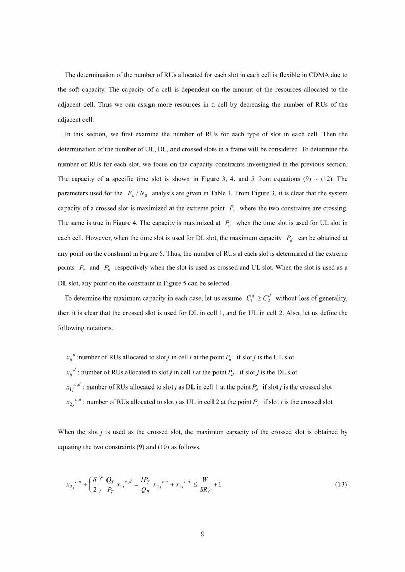
When the slot j is used as the crossed slot, the maximum capacity of the crossed slot is obtained by
equating the two constraints (9) and (10) as follows.
12
,1
,2
,1
,2 +≤+=
+
γδ
SRWxx
QPI
xPQ
x dcj
ucj
R
Tdcj
T
Tn
ucj (13)
9

Equation (13) is obtained under the assumption that γγγ == du . From (13), we have
+
−
−=
−
−
1)2()(2,
1 γδ SRW
IDQPIQD
x nnnT
TTnn
dcj and
+
−
−=
−
−−
1)2(
2,2 γδ
δSRW
IDPQDPD
x nnnT
Tnn
Tnn
ucj (14)
where means the maximum integer value which does not exceed x x .
When the two cells use time slot j for UL transmission, the maximum capacity of slot j is obtained by
equating two constraints in Figure 4. Thus, the maximum capacity in the UL slot is obtained when
11221 +≤+=+u
jjjj SRWNNNNγ
ζζ (15)
Thus, we have
+
+== 1
11
21u
uj
uj SR
Wxxγζ
(16)
Finally, when a timeslot is allocated to DL in the two cells, needs to satisfy the following
requirement.
dijx
dj
d
dj x
SRWx 12 1 −
+=
γ (17)
Let us denote , , and as the number of UL slots, DL slots, and crossed slots in a frame,
respectively. Clearly, S corresponds to the number of timeslots in a frame. The
capacity of the two cells, i.e., the number of total RUs allocated to cell 1 and 2, depends on the number of
, , and . From Equation (1) and (2), the capacity of two cells is computed as
uS
cS
dS cS
u + cd SSS +=
uS dS
uu
ju SxC 11 = (18)
cuc
juu
ju SxSxC ,
222 += (19)
10

cdc
jdd
jd SxSxC ,
111 += (20)
dd
jd SxC 22 = (21)
Now, to determine and that satisfy (17), notice the objective function given in Section 2.
Since our objective is to maximize the minimum ratio of residual capacity to the traffic load, the
maximization of the objective function is obtained when the following condition is satisfied.
djx1
djx2
d
dd
d
dd
TTC
TTC
2
22
1
11 −=
− (22)
Using the condition (22) and equations (14), (20) and (21), is given by djx1
+
−+= 0 ,
)(
1/
21
2,
111
ddd
cddc
jdd
ddj STT
STxSTSRWmaxx
γ (23)
Also, is obtained from (17). djx2
Since we have decided the maximum RUs at each slot, we are now interested in the determination of
the number of UL, DL, and crossed slots that maximize the objective function. An iterative search
algorithm is proposed by starting from the initial solution of , , and . To improve the objective
function value, the cell/link that gives the minimum ratio of residual capacity to the traffic load is selected
at each iteration. Then a slot is incremented to the link in the cell. Since the crossed slot is assumed to be
used as DL in cell 1 and UL in cell 2, when the UL (DL) slot is required in cell 1 (cell 2), the
improvement can be achieved only by increasing the UL (DL) slot.
uS dS cS
The heuristic search procedure may result in a local optimum, since , , and are updated
based on the number of slots obtained in the previous iteration. To prevent the local optimum, the search
process is continued even without the solution improvement. When no improvement is obtained for
consecutive iterations, then the algorithm is terminated. For the global optimum, an exhaustive search
may be considered in the two-cell model. However, the computational burden required for the solution
may well exceed that of the heuristic procedure as the problem size increases.
uS dS cS
RepT
The steps for the dynamic resource allocation algorithm (DRAA) are proposed as follows.
11

Step 1: Initialize the number of slots assigned to UL, DL, and crossed slots as = = . uS dS cS
Step 2: Compute , , , and as in Equations (18) ~ (21). uC1dC1
uC2dC2
Step 3: Compute the objective function and select the cell/link that gives the minimum objective function
value.
Step 4: In each case, update , , and to the direction that leads to the larger objective function
value of the two candidate solutions.
uS dS cS
When the DL of the cell 1 is the minimum: ( 1−uS , 1+dS , ) or (cS 1−uS , , ) dS 1+cS
When the UL of the cell 1 is the minimum: ( 1+uS , 1−dS , ) or (cS 1+uS , , ) dS 1−cS
When the DL of the cell 2 is the minimum: ( 1−uS , 1+dS , ) or ( , cS uS 1+dS , ) 1−cS
When the UL of the cell 2 is the minimum: ( 1+uS , 1−dS , ) or ( , cS uS 1−dS , ) 1+cS
Step 5: If the objective function value is not increased for the consecutive iterations, terminate the
algorithm. Otherwise, go to Step 2.
RepT
4. Computational Results and Discussions
The performance of the proposed dynamic resource allocation algorithm is examined by generating
three traffic load scenarios. In scenario 1, two cells have different UL/DL asymmetry. However, the total
traffic load is fixed to 80 RUs in each cell. The traffic load of cell 1 is fixed to RUs. Then,
the traffic asymmetry of cell 2 is varied such that . Thus, scenario 1 explains the situation
where two cells have almost the same number of users but the traffic asymmetry varies in one cell.
Scenario 2, which is the opposite situation of scenario 1, has the same UL/DL asymmetry in two cells
with different amounts of traffic loads. In scenario 2, we have and T RUs. The traffic
load in cell 2 is varied from RUs with the same UL/DL asymmetry as in the cell 1. Finally,
scenario 3 represents downlink hot-spot region. By fixing and T , is varied
from 40 to 110 RUs.
4011 == du TT
501 =d
202 =u dT2
800 2 ≤≤ dT
1T
1 =uT
30=u
401 =dT
90~102 =dT
Parameters used in this section are shown in Table 1. Typical values in cellular communication systems
are selected for , , , and W R TP γ . We set = 1.5 W because the maximum transmission power of
a BS is typically 20 W and the maximum available RUs in a slot is 14 if other cell interference is ignored.
TQ
7.0/ == Drδ is selected so that the area of the inner region and the outer region becomes the same. To
compare the performance of the proposed dynamic resource allocation algorithm, the MIP problems
12

formulated in Section 2 are solved with the ILOG CPLEX optimization software [21], which is executed
at 1 GHz CPU. Both the crossed slot and non-crossed slot allocation problems are solved with the traffic
loads given in the three scenarios.
Tables 2, 3, and 4 illustrate the computational result of the proposed DRAA and the CPLEX. The
solutions by the CPLEX for the crossed slot allocation (CSA) are the best solutions obtained by the
CPLEX. Due to the exponential growth of the branches in the process of CPLEX, it fails to obtain the
optimal solution for CSA. Thus, the running time of 10,000 seconds is chosen to insure a sufficient time
enough to guarantee the near optimal solution. The optimal solutions by the CPLEX for the non-crossed
slot allocation (NCSA) are also compared in the tables. In all scenarios, the CSA shows higher objective
function value than the NCSA, which means that the use of crossed slot is desirable to handle the traffic
asymmetry in the CDMA-TDD two-cell model. However, it is clear that the CSA by the CPLEX may not
be applicable to the real system due to the large CPU times. The proposed DRAA on the other hand can
solve the resource allocation problem in real time in any traffic scenarios.
Figure 6 shows the result of the scenario 1. The proposed DRAA well approximates the solution given
by the CSA. It also outperforms the optimal solutions by NCSA in most cases. The residual capacity of
three procedures increases as the UL load of cell 2 is increased. This is because the UL load in the two
cells can be simultaneously satisfied as in Figure 4 by increasing the UL slots.
In Figure 7 for the scenario 2, all the three procedures show that the residual capacity decreases as the
total traffic load increases. The performance of the proposed DRAA is not satisfactory in this scenario. It
shows that the DRAA is not so helpful when two cells have the same traffic asymmetry.
The superiority of the proposed DRAA over the NCSA is illustrated in Figure 8. In the scenario 3
which represents the downlink hot-spot situation, as the DL traffic at the hot-spot increases the DRAA
converges to the solution by the CSA. Moreover, the solution gap of the DRAA and the NCSA is
increased as the DL traffic is increased.
In the above analysis, it is clear that the CPLEX based CSA shows the best performance due to the
organized optimization by the branch and bound method. However, the running time of 10,000 seconds is
not adequate for the resource allocation in the real field. Thus, the CSA is experimented by limiting the
execution time. Figure 9 shows the performance of CSA when the running time is restricted to 1, 10, 100,
and 10,000 seconds for the scenario 1. The figure shows that the CSA with 10 or100 seconds of running
time well approximates the optimal solutions. However, the performance is unpredictable when the
13

running time is less than 10 seconds. Thus, the use of CSA is desirable if the system allows the execution
time of the resource allocation procedure to be approximately 10 seconds. However, the large execution
time of the algorithm may not be applicable in the environment where real time update of the resource is
required for the rapidly changing traffic load. Thus, the proposed DRAA will be advantageous over the
CSA when a bearer service instantaneously requires very high data rate for either UL or DL. By
rearranging resources to the UL and DL in each cell at the admission phase, the service blocking
probability of the system can be reduced dramatically.
Finally, figure 10 shows the use of , , and in the scenario 3. As shown in the figure, more
slots are used as the crossed slot as the difference of UL/DL asymmetry between the two cells increases.
It shows the effectiveness of the crossed slots in the proposed DRAA to tackle to the traffic asymmetry
problem.
uS dS cS
5. Conclusion
To cope with the future UL and DL traffic asymmetry problem, a dynamic resource allocation problem
is examined based on the CDMA-TDD. The problem is formulated as a mixed integer programming
problem which satisfies the traffic load and also maximizes the residual capacity for the unexpected
bearer services.
A dynamic resource allocation algorithm (DRAA) is proposed by considering the maximum capacity
of each type of time slot. The maximum capacity of a time slot used as either a crossed, UL, or DL slot is
examined by analyzing the constraints in the CDMA-TDD. The procedure then maximizes the
minimum residual capacity at each link in each cell by iteratively increasing or decreasing the number of
time slots assigned to the crossed, UL, and DL slots.
0/ NEb
Three scenarios of the traffic asymmetry patterns are employed to simulate various traffic situations.
Computational results show that the proposed DRAA effectively solves the resource allocation problem
when the two cells have different UL/DL asymmetries. Compared to the CPLEX, the DRAA is proved to
provide real-time solution updates that reflect the dynamic change of the UL and DL traffic load in each
cell.
14

Appendix: Linear conversion of the constraints (4) and (5) in Section 2
Note that equations (4) and (5) are nonlinear constraints in the formulation. The constraint (5) is
converted into (9) ~ (12) and they can be expressed as the linear function of as follows. ijN
1 ,1 if 1
121
21
21==
+≤+
+≤+
jj
ujj
ujj
uu
SRWNN
SRWNN
γζ
γζ
(24)
0 ,0 if 1 2121 ==+≤+ jjd
jj uuSR
WNNγ
(25)
==+≤+
+≤+0 ,1 if
1
12
21
21
21
jj
djj
R
T
uj
Tn
Tn
j
uu
SRWNN
QPI
SRWN
PQ
N
γ
γδ
(26)
==+≤+
+≤+1 ,0 if
1
12
21
21
21
jj
dj
R
Tj
ujj
Tn
Tn
uu
SRWN
QPIN
SRWNN
PQ
γ
γδ
(27)
where the normalized radius δ is defined as Dr /=δ . However, (24)~(27) are Either-Or constraints
where only one choice can be made among the four constraints. They must be reformulated into the linear
programming format where all specified constraints must hold [20]. To resolve the problem, we use the
well known method which introduces a very large positive value M [20]. For example, constraint (24) is
converted as follows by adding M.
MuMuSR
WNN jju
jj )1()1(1 2121 −+−++≤+γ
ζ (28)
MuMuSR
WNN jju
jj )1()1(1 2121 −+−++≤+γ
ζ (29)
The constraints (28) and (29) have the practical use only when , where the newly added
terms including M are eliminated and the constraints are identical to the original constraints. Otherwise,
they are satisfied automatically because M is much larger than the left-hand side of the inequalities.
121 == jj uu
15

Constraints (25) ~ (27) are also converted in the same way.
MuMuSR
WNN jjd
jj 2121 1 +++≤+γ
(30)
MuMuSR
WNPQN jj
uj
Tn
Tn
j 2121 )1(12
+−++≤+γ
δ (31)
MuMuSR
WNNQPI
jjd
jjR
T2121 )1(1 +−++≤+
γ (32)
MuMuSR
WNNPQ
jju
jjT
nT
n)1(1
2 2121 −+++≤+γ
δ (33)
MuMuSR
WNQPI
N jjd
jR
Tj )1(1 2121 −+++≤+
γ (34)
By replacing (5) with (28) ~ (34), the non-linear constraint (5) is converted into the linear form.
The linear conversion of (4) can also be done with the help of M. (4) is nonlinear because the product
of two variables exists. Let Y = . Then, , which means ijij Nu ij ijij Nu
==
=0 if 01 if
ij
ijijij u
uNY
1 if =
≥≤
ijijij
ijij uNYNY
(35)
0 if 00
=
≥≤
ijij
ij uYY
(36)
In (35) and (36), and Y should be satisfied regardless of the value of . Adopting M to
(35) and (36), the rest constraints are expressed as follows.
ijij NY ≤ 0≥ij iju
ijijij NuMY ≥−+ )1( (37)
MuY ijij ≤ (38)
Thus, all constraints of the formulation for the resource allocation problem shown in Section 2 are
16

expressed as linear inequalities.
References
[1] 3GPP Technical Specification 25.221, Physical Channels and Mapping of Transport Channels onto
Physical Channels (TDD), http://www.3gpp.org.
[2] 3GPP Technical Specification 25.222, Multiplexing and Channel Coding (TDD), http://www.3gpp.org.
[3] 3GPP Technical Specification 25.223, Spreading and Modulation (TDD), http://www.3gpp.org.
[4] 3GPP Technical Specification 25.224, Physical Layer Procedures (TDD), http://www.3gpp.org.
[5] M. Haardt, A. Klein, R. Koehn, S. Oestreich, M. Purat, V. Sommer, and T. Ulrich, The TD-CDMA
Based UTRA TDD Mode, IEEE Journal on Selected Areas in Communications, Vol. 18, No. 8, 2000.
[6] H. Holma and A. Toskala, WCDMA for UMTS, Wiley and Sons, 2000.
[7] 3GPP Technical Specification 25.922, Radio Resource Management Strategies, http://www.3gpp.org.
[8] O. Lehtinen and J. Kurjenniemi, UTRA TDD Dynamic Channel Allocation in Uplink with Slow
Reallocation, IEEE VTC, Spring, 2003.
[9] V. Huang and W. Zhuang, Optimal Resource Management in Packet-Switching TDD CDMA Systems,
IEEE Personal Communications, 2000.
[10] T. Kreingchaiyapruk and I. Forkel, Adaptive Switching Point Allocation in TD/CDMA Systems,
IEEE VTC, Fall, 2002.
[11] G.. Zhang and E. Zeira, Fast Permutation Based Time Slot Allocation for 3G WCDMA TDD Systems,
IEEE VTC, Spring, 2003.
[12] W. S. Jeon and D. G. Jeong, Comparison of Time Slot Allocation Strategies for CDMA/TDD
Systems, IEEE Journal on Selected Areas in Communications, Vol. 18, No. 7, 2000.
[13] J. Lee,Y. Han, and D. Kwon, An Adaptive Time Slot Allocation Strategy for W-CDMA/TDD System,
IEEE VTC, Spring, 2001.
[14] F. Nazzarri and R. F. Ormondroyd, An Effective Dynamic Slot Allocation Strategy Based on Zone
Division in WCDMA/TDD Systems, IEEE VTC, Fall, 2002.
[15] H. Yomo and S. Hara, An Up-link/Down-link Asymmetric Slot Allocation Algorithm in
CDMA/TDD-Based Wireless Multimedia Communications Systems, IEEE VTC, Fall, 2001.
[16] D. G. Jeong and W. S. Jeon, Time Slot Allocation in CDMA/TDD Systems for Mobile Multimedia
17

Services, IEEE Communication Letters, Vol. 4, No. 2, 2000.
[17] H. Haas and S. McLaughlin, A Dynamic Channel Assignment Algorithm for a Hybrid
TDMA/CDMA-TDD Interface Using the Novel TS-Opposing Technique, IEEE Journal on Selected Areas
in Communications, Vol. 19, No. 10, 2001.
[18] C. Mihailescu, X. Lagrange, Ph. Godlewski, and A. G. Acx, Dynamic Resource Allocation in Locally
Centralized Cellular Systems, IEEE VTC, Spring, 1998.
[19] S. H. Wie and D. H. Cho, Time Slot Allocation Scheme based on a Region Division in CDMA/TDD
Systems, IEEE VTC, Spring, 2001.
[20] F. S. Hillier and G. J. Lieberman, Introduction to Operations Research, Sixth Edition, McGraw-Hill,
1995.
[21] ILOG CPLEX 7.0, http://www.ilog.com.
18

10 ms frame, 15 Slots
Cell 1
Cell 2
Crossed Slots151413121110987654321Slots
:Uplink Slot :Downlink Slot
10 ms frame, 15 Slots
Cell 1
Cell 2
Crossed Slots151413121110987654321Slots
:Uplink Slot :Downlink Slot
Figure 1. Crossed slots in TDD system
BS 1 BS 2MS 1MS 2
Uplink Cell Downlink Cell
BS 1 BS 2MS 1MS 2
Uplink Cell Downlink Cell
Figure 2. Interference problem in a crossed slot
0
2
4
6
8
10
12
14
16
18
0 5 10
Uplink Cell
Dow
nlin
k C
ell
15
cP
0
2
4
6
8
10
12
14
16
18
0 5 10
Uplink Cell
Dow
nlin
k C
ell
15
cP
Figure 3. Capacity of a time slot: Crossed slot case
19

0
2
4
6
8
10
12
14
16
18
0 5 10 15
Cell 1
Cell
2
uP
0
2
4
6
8
10
12
14
16
18
0 5 10 15
Cell 1
Cell
2
uP
Figure 4. Capacity of a time slot: UL slot case
0
2
4
6
8
10
12
14
16
0 5 10 15
Cell 1
Cell
2
dP
0
2
4
6
8
10
12
14
16
0 5 10 15
Cell 1
Cell
2
dP
Figure 5. Capacity of a time slot: DL slot case
Table 1. Parameters used for analysis 0/ NEb
Parameters Values
W 5 MHz
R 8 Kbps
TQ 1.5 W
TP nδ×125 mW
δ )/( Dr 0.7
γ (= uγ = dγ ) 5 dB
20

Table. 2 Computational result in Scenario 1
CSA NCSA DRAA UL:DL load
in cell 2 Objective
value
CPU time
(seconds)
Objective
value
CPU time
(seconds)
Objective
value
CPU time
(seconds)
0:80 0.468 10,000* 0.291 2.080 0.350 0.00002
10:70 0.550 10,000* 0.375 1.950 0.500 0.00003
20:60 0.650 10,000* 0.400 6.670 0.517 0.00004
30:50 0.740 10,000* 0.550 3.980 0.650 0.00003
40:40 0.775 10,000* 0.625 18.440 0.625 0.00002
50:30 0.840 10,000* 0.600 16.000 0.775 0.00003
60:20 0.825 10,000* 0.625 22.980 0.767 0.00001
70:10 0.825 10,000* 0.675 17.250 0.700 0.00004
80:0 0.825 10,000* 0.630 7.470 0.671 0.00001
*: Terminated by the time limit
Table. 3 Computational result in Scenario 2
CSA NCSA DRAA UL:DL load
in cell 2 Objective
value
CPU time
(seconds)
Objective
value
CPU time
(seconds)
Objective
value
CPU time
(seconds)
6:10 1.367 10,000* 1.300 27.020 1.170 0.00002
12:20 1.200 10,000* 1.000 7.350 1.000 0.00003
18:30 1.000 10,000* 0.767 9.550 0.733 0.00002
24:40 0.850 10,000* 0.700 2.340 0.680 0.00004
30:50 0.680 10,000* 0.540 2.740 0.520 0.00002
36:60 0.517 10,000* 0.400 0.660 0.400 0.00002
42:70 0.371 10,000* 0.262 5.150 0.238 0.00001
48:80 0.229 10,000* 0.104 11.260 0.083 0.00003
54:90 0.129 10,000* 0.000 5.140 0.000 0.00003
*: Terminated by the time limit
21
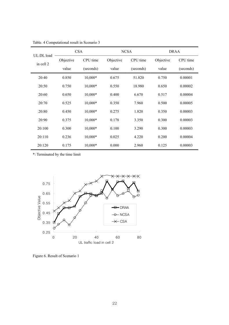
Table. 4 Computational result in Scenario 3
CSA NCSA DRAA UL:DL load
in cell 2 Objective
value
CPU time
(seconds)
Objective
value
CPU time
(seconds)
Objective
value
CPU time
(seconds)
20:40 0.850 10,000* 0.675 51.820 0.750 0.00001
20:50 0.750 10,000* 0.550 18.980 0.650 0.00002
20:60 0.650 10,000* 0.400 6.670 0.517 0.00004
20:70 0.525 10,000* 0.350 7.960 0.500 0.00005
20:80 0.450 10,000* 0.275 1.820 0.350 0.00003
20:90 0.375 10,000* 0.178 3.350 0.300 0.00003
20:100 0.300 10,000* 0.100 3.290 0.300 0.00003
20:110 0.236 10,000* 0.025 4.220 0.200 0.00004
20:120 0.175 10,000* 0.000 2.960 0.125 0.00003
*: Terminated by the time limit
0.25
0.35
0.45
0.55
0.65
0.75
0 20 40 60 80
UL traffic load in cell 2
Obje
ctive
Valu
e
DRAA
NCSA
CSA
Figure 6. Result of Scenario 1
22

0
0.2
0.4
0.6
0.8
1
1.2
1.4
1.6
0.0 0.5 1.0 1.5 2.0
Ratio of traffic load: cell 1/cell 2
Obje
ctive
Valu
e
DRAA
NCSA
CSA
Figure 7. Result of Scenario 2
0
0.1
0.2
0.3
0.4
0.5
0.6
0.7
0.8
0.9
30 50 70 90 110 130
DL traffic load in cell 2
Obje
ctive
Valu
e
DRAA
NCSA
CSA
Figure 8. Result of Scenario 3
23

0.3
0.4
0.5
0.6
0.7
0.8
0 10 20 30 40 50 60 70 80
UL traffic load in cell 2
Obje
ctive
Valu
e
DRAA
CSA_10,000s
CSA_100s
CSA_10s
CSA_1s
Figure 9. Performance of the CSA with regard to the time in Scenario 1
1
2
3
4
5
6
7
8
9
10
40 50 60 70 80 90 100 110 120
DL traffic load in cell 2
Num
ber of S
lots
Su
Sc
Sd
Figure 10. Number of Su, Sc, and Sd in Scenario 3
24


