
TITLE: Installation of Multiple Deck-Girder Bridge Spans Utilizing A Rail-Mounted Launching Truss/Gantry Crane on Amtrak’s Empire Line AUTHORS: Paul DelSignore, Senior Director Structures Amtrak 2955 Market Street, Box 55 Philadelphia, PA 19104 215-349-7000 [email protected] Joshua Kessler, Senior Engineer Structures Amtrak 2955 Market Street, Box 55 Philadelphia, PA 19104 215-349-7477 [email protected] Paul H. Markelz, President Rcrane 9419 Third Avenue Cary, IL 60013 630-258-1240 [email protected] WORD COUNT 3622 ABSTRACT During the fall of 2011, Amtrak utilized for the first time a rail-mounted
launching truss/gantry crane (gantry crane) to install multiple bridges over a four week
period on Amtrak’s Empire Line in Upstate NY. The use of a rail-mounted gantry crane
in this instance was an economical and safe choice for Amtrak versus using conventional
crane equipment. This paper will discuss the differences between using this type of
equipment versus conventional equipment, and the many benefits Amtrak experienced on
this project.
Amtrak runs approximately 28 trains per day on this busy corridor between
Albany’s Capital Region and New York City. Bridge 126.03(36’) and Bridge 126.67
(30’) are both open-deck deck-girder structures originally built for double track by the
New York Central Railroad from 1916-17. As part of Amtrak’s State of Good Repair
initiative, plans and specifications were developed in 2004 to replace the open deck
bridges with ballasted decks, allowing track speeds to be increased. Funding constraints
delayed the actual installation until 2011.
Amtrak’s choice to utilize a rail-mounted gantry crane allowed the actual bridge
installation to take place during normal work hours since the gantry crane system and
material cars that handled both the old and new spans occupied only the track in which
the installation was taking place. Amtrak trains could still utilize the adjacent track.
Conventional crane equipment would have required a double track outage for an
extended period of time and most likely night and weekend outages.

BACKGROUND Amtrak’s Empire service between New York City’s Penn Station and Albany, NY
(Capital Region) runs alongside the east bank of the Hudson River along portions of the
storied New York Central’s “Water Level Route”(from New York City to eventually
Chicago) and former Hudson River Railroad (Figure 1). The origins of this line are
traced to the original railway built between Troy, NY and Greenbush, NY just south of
present day Rensselaer. The Troy and Greenbush Railroad was chartered in 1845 and
opened later that year, connecting southern Troy to East Albany along the east side of the
Hudson River. The Hudson River Railroad was chartered May 12, 1846, to extend this
line from East Albany, NY to New York City. The full line opened October 3, 1851.
Cornelius Vanderbilt obtained control of the Hudson River Railroad in 1864, eventually
making it part of his ever growing New York Central Railroad.
Presently Amtrak runs approximately 28 trains per day on this busy corridor
between Albany’s Capital Region and New York City. Several of these trains continue
West of Albany to Buffalo, NY while some service continues to Rutland, VT (Ethan
Allen Service) and Montreal (Maple Leaf Service). Connections can be made in
Rensselaer (east of Albany) to further points east (Boston) and west (Chicago) via
Amtrak’s Lake Shore Limited. Amtrak ridership on the portion between New York Penn
Station and the Capital Region exceeded one million passengers in 2011. In addition to
Amtrak service on the Hudson Line, Metro North (part of New York City MTA)
commuter rail service serves New York’s Grand Central Station and Poughkeepsie, NY
with much more frequent commuter service. The Hudson Line is primarily owned by
CSX north of the New York metro area (Poughkeepsie). The line south of Poughkeepsie
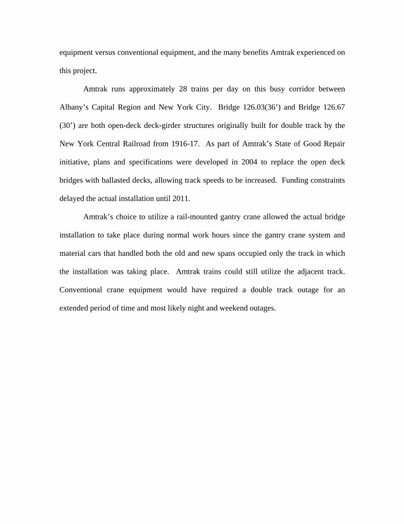
going towards New York City is owned and operated by Metro North, with Amtrak
having trackage rights over this portion. Amtrak is in the process, as of October 2011, of
securing a long-term lease agreement for the portion of the line between Poughkeepsie
and Schenectady. Amtrak would, in cooperation with the State of New York, bring more
double track capacity, higher speeds and increased train capacity to this growing rail
corridor.
Figure 1: Amtrak’s Empire Service
In order to accommodate future capacity and bring Amtrak’s assets up to a state
of good repair, several bridge rehabilitation projects have been identified. Replacement
bridge spans for Bridge 126.03 over Light House Creek and Bridge 126.67 over
Waterway Creek were designed by Amtrak and programmed for replacement during the
fall of 2011. These bridges are located in two-track territory in Stuyvesant, NY. Safe
construction and limited work windows are paramount issues for Amtrak when
undertaking bridge replacements on busy corridors such as this. For this project Amtrak
elected to utilize a rail-mounted gantry crane versus conventional lifting equipment. This
paper will discuss the differences between using this type of equipment versus
conventional equipment and the many benefits Amtrak experienced during this project.
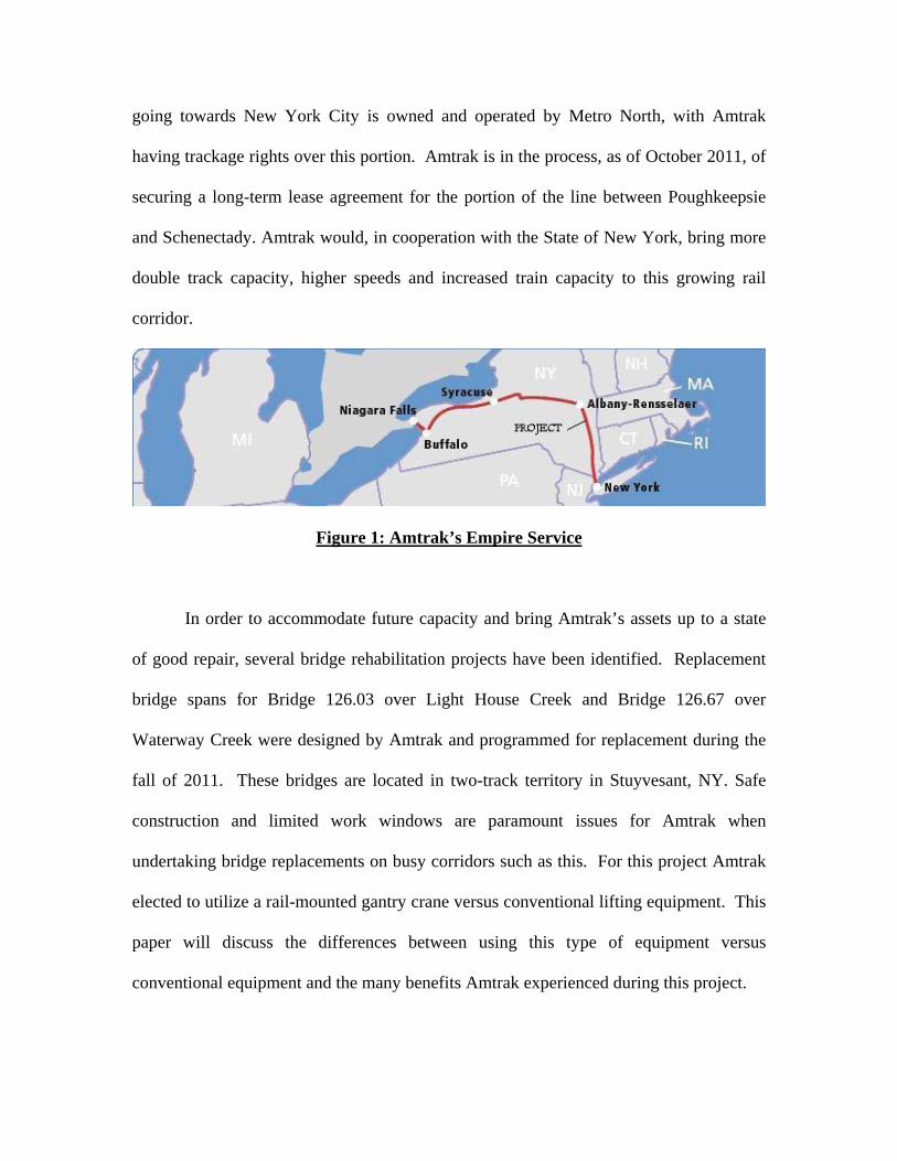
BRIDGE CONDITIONS The existing bridge crossings at mileposts 126.03 and 126.67 were constructed in
1917 and 1916, respectively, by The American Bridge Company. Both structures consist
of typical turn of the century riveted multi-plate deck girders set on concrete abutments
founded on wood piling. The bridge decks were open timber decks. The bridge span for
Bridge 126.03 is 36 feet while Bridge 126.67 is 30 feet. Both bridges are double track
simply supported single spans. Over the years, the abutments have performed well,
requiring little attention and maintenance. Timber deck replacement intervals were
normal based on the bridge location and volume of traffic. The steel bridge
superstructure exhibits fairly normal section loss to the main structural girders and
elements, and more severe section loss to the secondary members, mostly the lateral
systems and connecting plates.
Figure 2: Bridge 126.67 Pre Change-out

The existing paint coating systems on the bridge appeared to be very old (perhaps
over 40+ years), and exhibited much flaking and cracking. Paint was non-existent on
much of the structure as evidenced by numerous locations of rust and exposure of the
red-lead primer throughout. Typically due to railroad downsizing, less attention over the
years had been paid to bridge painting and to bridge secondary members. No prior major
rehabilitation was evident to either of these structures at the time that Amtrak determined
it wanted to convert these open-deck bridges to ballasted decks, which would reduce
maintenance while increasing train speeds on this rail line. Most, if not all, of the
secondary members and connection plates appeared to still be original vintage, and
overall in a fair condition for their age (90+ years old). The concrete bearing blocks
underneath all bridge bearings were severely cracked and worn, warranting total
replacement.
In some cases, when Amtrak decides to convert open-deck bridges to ballasted-
deck, the existing superstructure is rehabilitated and new solid deck is installed. In this
case, however, it was deemed necessary to completely replace the superstructure due to
the existing conditions, and the amount of rehabilitation that would have been required to
achieve the desired bridge rating.
BRIDGE DESIGN Typically for small to medium span replacements (less than 60’), Amtrak usually
prefers to utilize what is referred to as “concrete encased I-beam” slab construction
(Figure 3). The Pennsylvania Railroad (PRR), one of Amtrak’s predecessor railroads,
developed this as a standard, and many examples of this type of bridge are still in use on

Amtrak’s system and on many other railroads. In this case, the steel I-beams are designed
to the current AREMA Chapter 15 Manual for Railway Engineering and Cooper E-80
railroad loading. The I-beams are spaced evenly and a monolithic concrete pour is made
that both encases the I-beams (except for the face of the bottom flange) and provides for
the deck and parapet (ballast retainer) complete. In the case of the replacement of these
two structures, two slabs per track consisting of five steel I-beams per slab (W24 x 146
for Bridge 126.03 & W21 x 111 for Bridge 126.67) were encased for each span
replacement. Amtrak utilized its own work crews in Wilmington, DE to fabricate the
spans/slabs directly on railroad flat cars. The slabs were then shipped via rail directly to
the project staging area. In most cases, minor modification and leveling of the bridge
seats is also required for the acceptance of the new slabs.
Figure 3: Encased I-Beam Design Drawing
PLANNING
Bridge installation and replacement projects involve resourceful planning,
attention to safety, proper budgeting, and a focus on minimizing track outages. The
planned replacement of bridges 126.03 and 126.67 was no different. Fundamental

principles of safety, quality, and production were the key drivers for the logistical
planning and coordination on this project. The gantry crane’s physical properties by
design allowed Amtrak to work during daylight hours, allowed continuous movement of
scheduled trains, and increased material handling safety for the benefit of the project.
The overall scope of the project involved replacing a total of 4 bridge spans on a
busy two-track railroad corridor. Much attention was paid to the various limiting factors
and mobilization logistics of using this gantry crane for the first time. The limitations of
the gantry crane, specifically the lifting capacity and clearance dimensions, were given
careful consideration to ensure that it was capable of safely handling all of the required
lifts.
Planning the installation was based on the operational advantages the gantry crane
presented versus a more conventional method. The gantry crane’s ability to reduce track
outages by allowing work crews to perform installation while occupying only one track
as well as providing a means to self transport all materials and bridge components to the
site presented substantial benefits. One of the most important attributes of the gantry
crane was its ability to allow the work to be performed during daylight hours, providing a
safer working environment for Amtrak construction employees. The gantry crane’s
interior working dimensions (inside to inside wheel lengths, interior width and interior
height) were heavily scrutinized to ensure that all of the required lifts had the proper
clearances. Estimated weights of all lifts were also evaluated to ensure that the gantry
crane had sufficient capacity to handle them safely. The gantry crane allows for a
maximum pick length of 57’, providing ample length to handle the replacement of the
maximum proposed bridge span length of 36’. It was also determined that the dual 40
ton overhead gantry hoists on the crane had more than enough capacity to handle the
project’s heaviest lift, estimated to be 58.7 tons.
Typically, Amtrak would utilize conventional crane equipment (either rail-
mounted, off-road or crawler types), which would have required a double track outage for
an extended period of time with perhaps nightly and weekend outages. Generally, the
cranes (possibly two large 250 ton capacity cranes) occupy the track where the bridge is
being replaced, and a work train with flat cars is positioned on the adjacent track to
collect the old spans and deliver the new. Amtrak’s choice to utilize a rail-mounted
gantry crane allowed the actual bridge installation to take place during normal work
hours while the gantry crane system and material cars that handled both the old and new
spans occupied only the track where the installation was taking place. Amtrak could still
run trains on schedule and unimpeded utilizing the adjacent track.
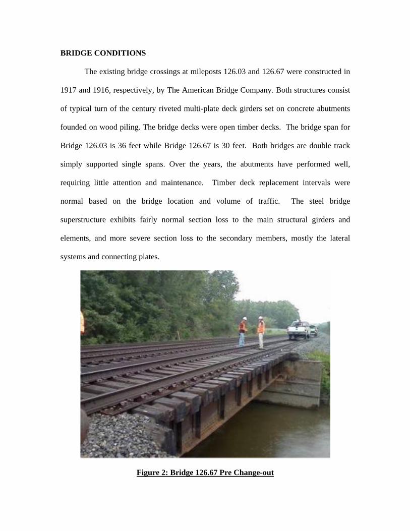
GANTRY CRANE CAPACITY AND SPECIFICATIONS
Figure 4: Gantry Crane Profile
The rail-mounted gantry crane system used on this project was developed by
Rcrane, LLC with collaboration from many of the Class 1 railroads. The rail-mounted
gantry crane was developed to maximize safety and productivity for bridge and track

renewal. The gantry crane is 89’ long, 10’ wide for travel (18’ wide in the fully open,
operating position), 19’-10” tall, and weighs 220,000 pounds. The gantry crane includes
two primary 40-ton capacity overhead hoists with combined capacity of 80 tons. The
unit also travels with an identical spare 40-ton hoist. The gantry crane is able to handle
components with maximum dimensions of 57’ long, 13’ wide, 8’ tall and a maximum
weight of 80 tons. The gantry crane is capable of full speed travel in a train consist with
eight flat cars. The flat cars are standard 89’ TOFC spec flatcars with modified guide
rails to enable the self-propelled heavy-duty material transporters (“Rmules” developed
by Rcrane, LLC) to safely and rapidly move materials over the decks. Together, the
heavy-duty transporters along with the flat cars feed materials to and from the gantry
crane operating area to enable the gantry crane system to deliver, demolish, install and
dispose of bridge and track materials, all within one trip from the staging yard.
CONSTRUCTION
Once the gantry crane was under contract and mobilized to Amtrak’s Rensselaer
yard, Amtrak coordinated the movement of all materials to the staging site. A 250 ton
highway crane was mobilized to hoist the new encased I-beam slabs onto the 89’ flat
cars. The rapid renewal work train consisted of five 89’ coupled flats behind the gantry
crane carrying new bridge material, and three coupled 89’ flat cars that were utilized for
post change-out waste material.
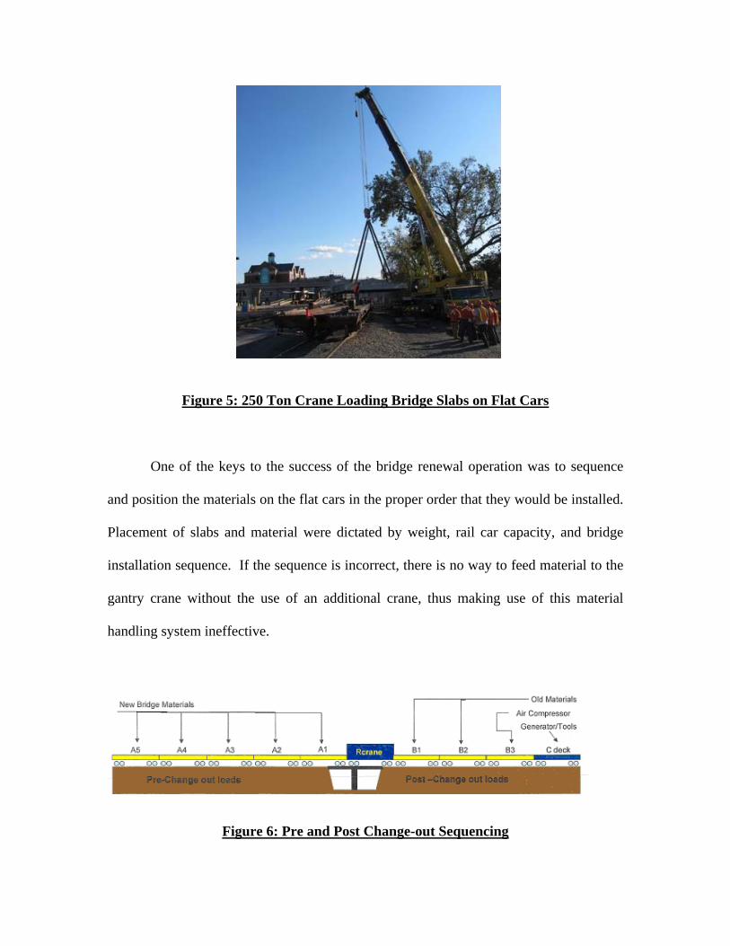
Figure 5: 250 Ton Crane Loading Bridge Slabs on Flat Cars
One of the keys to the success of the bridge renewal operation was to sequence
and position the materials on the flat cars in the proper order that they would be installed.
Placement of slabs and material were dictated by weight, rail car capacity, and bridge
installation sequence. If the sequence is incorrect, there is no way to feed material to the
gantry crane without the use of an additional crane, thus making use of this material
handling system ineffective.
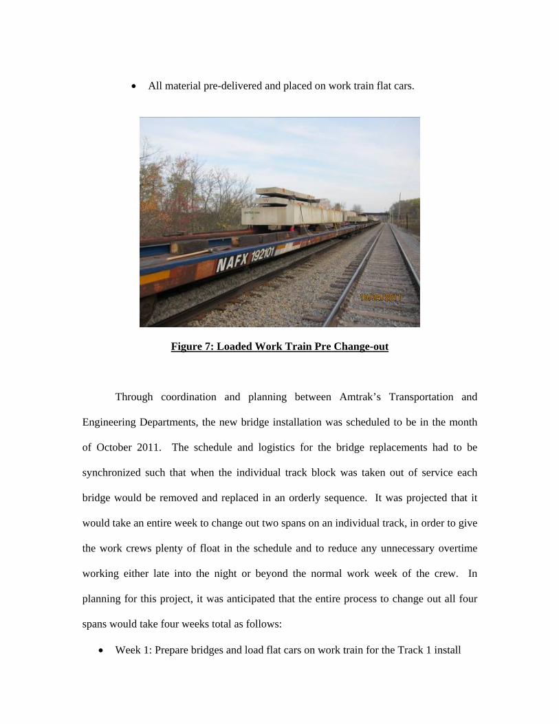
Figure 6: Pre and Post Change-out Sequencing

In reference to Figure 6 above, bridge slabs, track panels, and other materials
were staged as follows:
Flat Car Area Material Placement____________________________
A1 Br. 126.67-inner concrete encased I-beam slab and both precast bridge bearing pads
A2 Br. 126.67-outer concrete encased I-beam slab,
prefabricated track panel, waterproofing materials
A3 Br. 126.03-inner concrete encased I-beam slab and both precast bridge bearing pads
A4 Br. 126.03-outer concrete encased I-beam slab,
prefabricated track panel, waterproofing materials
A5 Work gang box, tools, concrete, additional materials
There was a great deal of work that needed to be accomplished prior to the “Big
Day” of the bridge change-outs. The approach used for the rapid renewal of one
complete track at a time focused on the sequencing and preparation of all materials prior
to the install. Work was sequenced from north to south, such that Bridge 126.67 would be
completed first followed by Bridge 126.03. Prior to the actual install, the following
activities were completed in order to decrease the amount of time that the track usage
would need to be restricted:
Precast bridge bearing pads were fabricated as opposed to a cast in place option which would have been more time consuming during the track outages.
Track department pre-measured for the rail cuts in existing rail to match
the new panel construction to expedite installation.
Track department pre-cut rail joints and applied joint bars in preparation for bridge change-out.
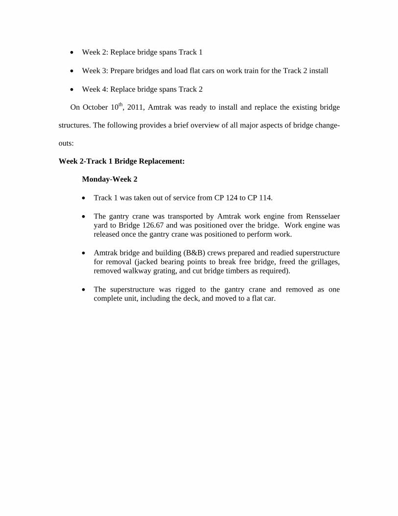
All material pre-delivered and placed on work train flat cars.
Figure 7: Loaded Work Train Pre Change-out
Through coordination and planning between Amtrak’s Transportation and
Engineering Departments, the new bridge installation was scheduled to be in the month
of October 2011. The schedule and logistics for the bridge replacements had to be
synchronized such that when the individual track block was taken out of service each
bridge would be removed and replaced in an orderly sequence. It was projected that it
would take an entire week to change out two spans on an individual track, in order to give
the work crews plenty of float in the schedule and to reduce any unnecessary overtime
working either late into the night or beyond the normal work week of the crew. In
planning for this project, it was anticipated that the entire process to change out all four
spans would take four weeks total as follows:
Week 1: Prepare bridges and load flat cars on work train for the Track 1 install
Week 2: Replace bridge spans Track 1
Week 3: Prepare bridges and load flat cars on work train for the Track 2 install
Week 4: Replace bridge spans Track 2 On October 10th, 2011, Amtrak was ready to install and replace the existing bridge
structures. The following provides a brief overview of all major aspects of bridge change-
outs:
Week 2-Track 1 Bridge Replacement:
Monday-Week 2
Track 1 was taken out of service from CP 124 to CP 114.
The gantry crane was transported by Amtrak work engine from Rensselaer yard to Bridge 126.67 and was positioned over the bridge. Work engine was released once the gantry crane was positioned to perform work.
Amtrak bridge and building (B&B) crews prepared and readied superstructure
for removal (jacked bearing points to break free bridge, freed the grillages, removed walkway grating, and cut bridge timbers as required).
The superstructure was rigged to the gantry crane and removed as one
complete unit, including the deck, and moved to a flat car.

Figure 8: Superstructure Removal
Tuesday-Week 2
After obtaining use of the adjacent track, the gantry crane began its operation by first spreading its trusses and prepping to set precast bridge bearing pads at Bridge 126.67.
B&B crews set the precast concrete bridge bearing pads with the gantry crane
and anchored them.
B&B crews set and anchored the inner precast bridge slab.

Figure 9: Precast Bridge Slab Installation
Wednesday-Week 2
After Train 234 passed work site, B&B crews set outer slab with gantry crane. B&B crews poured keyway between new slabs and began the waterproofing
procedure.
Amtrak track (Track) crews then set the track panel with the gantry crane and began the ballasting process.
Work train moved to Bridge 126.03 in preparation for replacement.
Thursday-Week 2
After Train 234 passed work site, B&B crews prepared for the removal of Bridge 126.03.
The superstructure was rigged to the gantry crane and removed as one
complete unit, including the deck, and then moved to a flat car.
Friday-Week 2
Complete day was lost due to rail traffic and transportation issues.
Saturday-Week 2
After Train 234 passed work site, B&B crews set both precast concrete bridge bearing pads with gantry crane and anchored them.
B&B crews set and anchored the inner and outer precast bridge slabs.
B&B crews poured keyway between new slabs and began the waterproofing
procedure.
Track crews then set the track panel with the gantry crane and began the ballasting process.
Work train moved back to staging yard in preparation for Track 2 bridge
replacements.
Sunday-Week 2
Track crews welded the track panels, surfaced the track and restored Track 1 back into service.
Week 3-Staging Yard
The work train was moved back to the staging yard. The flat cars were off-loaded of all the previous week’s work material and all of the new materials and bridge components for the Track 2 span replacements were loaded, positioned, and readied for installation for the following week.
Week 4-Track 2 Bridge Replacements: Monday-Week 4
Track 2 was taken out of service from CP 124 to CP 114.
The gantry crane was transported by work engine from Rensselaer yard to Bridge 126.67 and was positioned over the bridge.
B&B crews prepared and readied the superstructure for removal (jacked
bearing points to break free bridge, freed the grillages, removed walkway grating, and cut bridge timbers as required).

The superstructure was rigged to the gantry crane and removed as one complete unit, including the deck, and then moved to a flat car.
Figure 10: Removal of Old Span
B&B crews set both precast concrete bridge bearing pads with gantry crane and anchored them.
B&B crews set and anchored the inner and outer precast bridge slabs with the
gantry crane.
B&B crews poured keyway between new slabs and began the waterproofing procedure.
Track crews then set the track panel with the gantry crane and began the
ballasting process. Work train moved to Bridge 126.03 for the Track 2 bridge replacements. In one day – Existing superstructure was removed; and new bridge was
completely installed and prepared for track work.

Figure 11: Installation of Bridge Bearing Pad
Tuesday-Week 4
The gantry crane was in position at Bridge 126.67.
B&B crews prepared and readied superstructure for removal (jacked bearing
points to break free bridge, freed the grillages, removed walkway grating, and cut bridge timbers as required).
The superstructure was rigged to the gantry crane and removed as one
complete unit, including the deck, and then moved to a flat car. B&B crews set both precast concrete bridge bearing pads with gantry crane
and anchored them.
B&B crews set the inner and outer precast bridge slabs with the gantry crane.
B&B crews then poured keyway between new slabs and began the waterproofing procedure.
In one day - Existing superstructure was removed and new bridge was
completely installed and prepared for track work.

Figure 12: Installation of Track Panel
Wednesday-Week 4
Track crews completed the track panel installation with the gantry crane, performed ballasting procedure, and surfaced the track.
The work train was then transported back to the staging yard, and Track 2 was
restored to service.
The 250 ton crane was used to unload the post change-out material off of the work train in the staging yard area.
B&B crews worked to complete all remaining items including walkway and
handrail installation, and final clean-up.
**Of Note: In three working days during daylight hours two bridge spans were successfully replaced on Track 2 and the track was restored to normal service. Full service train traffic was run on the adjacent track unimpeded.

COSTS AND EFFICIENCIES
During the first week of the actual bridge change-out (Week 2 of the project),
Amtrak crews successfully replaced two spans in seven days. The installation was
delayed due to traffic conditions and the work crew’s learning curve with this new piece
of equipment (gantry crane and heavy-duty transporters). The group quickly learned the
limitations and capacities of the machinery, and the need to have the gantry crane’s
trusses fully spread out to make substantial picks and/or move material. Once the group
was more familiar with these procedures, two spans were changed out in two days, during
the more successful Week 4, with the track work being completed by day three.
Figure 13: Bridge 126.67 Complete

In planning for this project Amtrak determined that if they had used conventional
crane equipment and a work train to perform the bridge change-outs, much of this work
would have still involved a single track outage, and most of the heavy lifting would had
to have been performed at night (on overtime) during a double track outage since the
conventional lifting equipment would either be continuously fouling or occupying the
adjacent track. Amtrak performed a post-project cost/benefit analysis comparing total
costs of using the rail-mounted gantry crane with Amtrak crews working only during
daylight hours versus using conventional equipment with much more premium time
(overtime). Amtrak determined that there was a substantial savings, approximately 25%,
from use of the gantry crane utilizing this installation method. Complete final analysis on
the beneficial use of the gantry crane determined that the use of daylight for this
application and reducing the amount of adjacent track occupancy proved to be an extreme
advantage and allowed Amtrak crews to provide an efficient means of bridge
construction that increased construction safety and allowed our crews to produce a
quality transportation product.
TABLE AND FIGURE LISTING
Figure 1: Amtrak’s Empire Service
Figure 2: Bridge 126.67 Pre Change-out
Figure 3: Encased I-Beam Design Drawing
Figure 4: Gantry Crane Profile
Figure 5: 250 Ton Crane Loading Bridge Slabs on Flat Cars
Figure 6: Pre and Post Change-out Sequencing
Figure 7: Loaded Work Train Pre Change-out
Figure 8: Superstructure Removal
Figure 9: Precast Bridge Slab Installation
Figure 10: Removal of Old Span Figure 11: Installation of Bridge Bearing Pad Figure 12: Installation of Track Panel Figure 13: Bridge 126.67 Complete
BIOGRAPHICAL SKETCHES
Paul DelSignore, PE
Paul DelSignore is Amtrak’s Senior Director Structures and has been with Amtrak for the past five years. His previous eight years were spent in engineering consulting as a Vice-President with Transystems and as a Market Sector Leader with Bergmann Associates. Paul started his career with Conrail and later worked with CSX post-merger. He has held the positions of Assistant and Supervisor Structures, B&B Engineer, Bridge Production Engineer and Director of Structures. He holds a BS in Civil Engineering from Penn State, a MBA from the University of Pittsburgh, and is a PE in the State of Pennsylvania. Paul is a member of AREMA Committee 8-Concrete and resides in the western suburbs of Philadelphia with his two teenage sons. Joshua Kessler Joshua Kessler is the Senior Engineer of Structures Production for Amtrak (National Railroad Passenger Corporation), a position he has held for 4 years. Joshua joined Amtrak after time spent at Stantec, where he served as a structural engineer. He holds a BS in Civil Engineering from Clarkson University, is an AREMA member, and now resides in the western suburbs of Philadelphia. Paul H. Markelz Paul is the President of Rcrane, LLC since 1993 and resides in Chicago with his wife and five children. Rcrane is committed to the safety and productivity of railroad renewal projects with patented machinery and material design/supply services. Paul began his career in 1988 as Central Division Engineer for Dywidag leading the design and supply of post-tensioning steel for the construction of over 150 bridges. Paul graduated from Marquette University in 1988 with a Bachelors in Civil/Structural Engineering. From '86- '88 Paul served as a co-op student engineer with HNTB in Milwaukee.


