
Toroidal Roller Bearings TORBLonger rating life and operating life –
higher technical and economic performance

Foreword
Schaeffler Technologies Schaeffler Technologies with its brands INA and FAG is a leading worldwide supplier of rolling bearings, spherical plain bearings, plain bearings, linear products, accessories specific to bearings and comprehensive maintenance products and services.It has approximately 40 000 catalogue products manufactured as standard, providing an extremely wide portfolio that gives secure coverage of applications from all 60 industrial market sectors.The central factors responsible for this success are our outstanding strength in innovation, our global focus on local customer proximity, highly developed manufacturing methods, extremely high quality standards in all processes and our ability to transform specific customer requirements quickly and accurately into cost-effective solutions. Against this background of expertise, knowledge and experience together with our wide range of catalogue items, we see ourselves as a high performance, customer focussed partner.
TORB – what is it? The toroidal roller bearing TORB is a new type of rolling bearingfrom Schaeffler. It is a single row rolling bearing with long, slightly crowned rollers. When used as a non-locating bearing, it combines the self-alignment function of a spherical roller bearing with the axial displacement facility of a cylindrical roller bearing.

2 TPI 232 Schaeffler Technologies

Schaeffler Technologies TPI 232 3
Page
Contents
Toroidal roller bearingsFeatures............................................................................... 4
X-life ............................................................................... 5The ideal non-locating bearing concept ............................ 6Operating temperature..................................................... 7Lubrication ...................................................................... 7Cages .............................................................................. 7Suffixes ........................................................................... 7Product range .................................................................. 8Interchangeability............................................................ 8Bearing housings............................................................. 8Products for mounting, maintenance and monitoring........ 9
Design and safety guidelines................................................ 10Permissible skewing ........................................................ 10Axial displacement facility ............................................... 10Equivalent dynamic and static bearing load...................... 15Minimum load ................................................................. 16Speeds............................................................................ 19Tolerances....................................................................... 19Design of bearing arrangements....................................... 20
Accuracy .............................................................................. 26Radial internal clearance ................................................. 26
Dimension tablesToroidal roller bearings, cylindrical or tapered bore .......... 30
Application examplesPaper industry...................................................................... 50
Steel industry....................................................................... 52
Ventilators ........................................................................... 54
Marine propulsion systems .................................................. 56

4 TPI 232 Schaeffler Technologies
Toroidal roller bearings
Features FAG toroidal roller bearings are single row bearings with long, crowned rollers. The concave raceways in the inner ring and outer ring are concentric relative to the centre of the bearing. The raceway profiles are matched to each other and ensure optimum distribution of stresses in the bearing as well as low operating friction.The rollers are self-guiding. They will always automatically adoptthe position at which the load is distributed over the length ofthe roller. This is also the case if the rings are displaced or skewed relative to each other, Figure 1.The toroidal roller bearing combines the angular adjustment facility of a spherical roller bearing with the unconstrained axial displace-ment facility of a cylindrical roller bearing. It offers a very high radial load carrying capacity within a small design envelope.Toroidal roller bearings offer an ideal and operationally reliable solution to the problem of achieving a locating/non-locating bearing. Since axial displacement is compensated within the toroidal roller bearing, the constraining forces occurring are very slight and can be disregarded.
A particularly high load carrying capacity is available in the full complement design, indicated by the suffix V, Figure 2.Full complement toroidal roller bearings are intended for applications such as continuous casting lines.
� Initial position� Inner ring with tilting
� Inner ring with axial displacement� Inner ring with displacement and tilting
Figure 1Toroidal roller bearing
(tilting and axial displacement) 0008
9382
0008
9382
Figure 2Full complement
toroidal roller bearing 0008
5C7F
0008
5C7F

Schaeffler Technologies TPI 232 5
X-life is the premium brand that identifies particularly high performance products under the FAG and INA brands.They are characterised by a long rating life and operating life, due to the use of the most modern manufacturing techniques, Figure 3.They lead to better and more uniform surfaces and contact areas and thus optimised load distribution in the bearing.This opens up expanded design possibilities:■ Under the same load and with an unchanged design envelope,
X-life bearings have a longer rating life and maintenance intervals can be extended.
■ Conversely, an X-life bearing in the same design envelope and with the same rating life can support higher loads.
■ Where the rating life and load remain unchanged, X-life bearings allow higher performance density, facilitating optimisation ofthe design envelope and reductions in mass.
As a result, the X-life bearing makes a significant contribution to improved overall cost-efficiency under the philosophy of Total Cost of Ownership (TCO).
Figure 3Key characteristics of X-life 00
0872
5200
0872
52

6 TPI 232 Schaeffler Technologies
Toroidal roller bearings
The ideal non-locating bearingconcept
Where a shaft is liable to temperature-induced elongation and misalignment defects, the non-locating bearing is a particularly important concept. In this case, toroidal roller bearings have proved ideal as non-locating bearings, Figure 4.In comparison with normal non-locating bearing arrangements,they offer significant advantages:■ Substantial changes in shaft length are compensated
without constraint between the raceways and the rolling elements within the bearing.
■ Even more considerable axial displacements have no effecton the locating bearing.
■ There is no axial distortion of the bearing system.
Principal areas of application The principal areas of application of toroidal roller bearings are:■ steelworks and rolling mills■ conveying equipment and belt installations■ paper machinery■ continuous flow machines■ crushers■ gearboxes■ textile machinery■ machinery for food processing■ agricultural equipment.
Requirements The requirements placed on the bearings are:■ constraint-free non-locating bearing function■ high load carrying capacity■ high operational reliability■ long operating life■ low maintenance outlay■ low operating costs■ compact construction■ high performance capability.
Figure 4The ideal non-locating bearing
concept 0008
5C88
0008
5C88

Schaeffler Technologies TPI 232 7
Operating temperature Toroidal roller bearings are dimensionally stable up to +200 °C. Bearings with metal cages can be used at operating temperatures from –30 °C to +200 °C.
Lubrication Open toroidal roller bearings can be lubricated with oil or grease. Lubricant is introduced from one side and exits on the opposing side.
Cages Toroidal roller bearings are essentially available in two designs:■ full complement■ bearing with cage.Full complement bearings have a higher load carrying capacity than the variant with a cage.Depending on the series and bearing size, toroidal roller bearings are supplied as standard with the following cage designs:■ roller-guided sheet steel cage, single-piece,
no suffix■ roller-guided brass window cage,
suffix M■ brass window cage, guided on inner ring,
suffix M1B.
SuffixAvailable designs Suffixes Description
XL X-life quality
K Tapered bore, taper ratio 1:12
K30 Tapered bore, taper ratio 1:30
C2 Radial internal clearance C2/Group N (smaller than normal)
C3 Radial internal clearance C3/Group 3 (larger than normal)
C4 Radial internal clearance C4/Group 4 (larger than normal C3)
C5 Radial internal clearance C5 (larger than C4)
V Full complement cylindrical roller set
M Brass window cage, guided by rollers
M1B Brass window cage, guided on inner ring
W209B Inner ring made from case hardening steel
H262A Full complement TORB without retaining ring
8 TPI 232 Schaeffler Technologies
Toroidal roller bearings
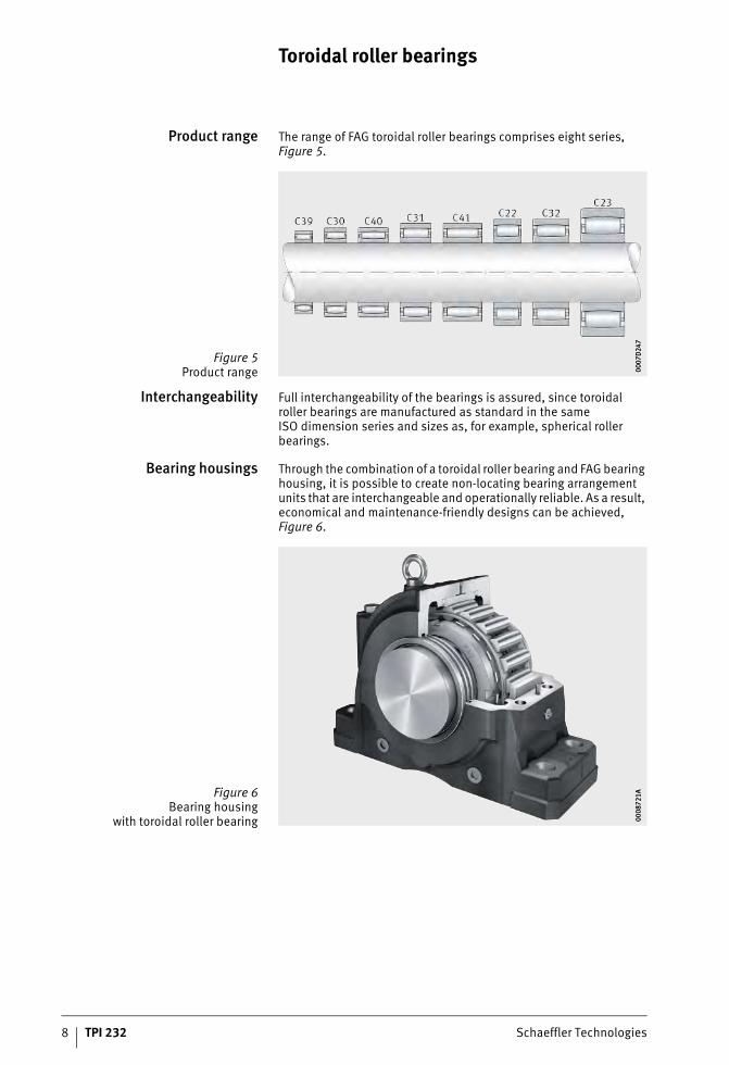
Product range The range of FAG toroidal roller bearings comprises eight series, Figure 5.
Interchangeability Full interchangeability of the bearings is assured, since toroidal roller bearings are manufactured as standard in the sameISO dimension series and sizes as, for example, spherical roller bearings.
Bearing housings Through the combination of a toroidal roller bearing and FAG bearing housing, it is possible to create non-locating bearing arrangement units that are interchangeable and operationally reliable. As a result, economical and maintenance-friendly designs can be achieved, Figure 6.
Figure 5Product range 00
07D
247
0007
D24
7
Figure 6Bearing housing
with toroidal roller bearing 0008
721A
0008
721A

Schaeffler Technologies TPI 232 9
Products for mounting,maintenance and monitoring
In order to ensure that the high performance capability of FAG toroi-dal roller bearings can be exploited to the full, particular attention must be paid to their particular characteristics in terms of mounting and dismounting, lubrication, sealing and maintenance, Figure 7.The methods to be used in mounting and dismounting are com-prehensively described in publication MH 1, Mounting of Rolling Bearings. In those cases where a production stoppage can incur heavy costs, monitoring of rolling bearings is both advisable and cost-effective. An overview of suitable tools, measuring devices and diagnostic equipment can be found in Catalogue IS 1, Mounting and Maintenance of Rolling Bearings.
Figure 7Mounting of toroidal roller bearing 00
0B02
4800
0B02
48

10 TPI 232 Schaeffler Technologies
Toroidal roller bearings
Design and safety guidelinesPermissible skewing Toroidal roller bearings can be tilted by an angle of up to 0,5°
between the centre axes of the inner ring and outer ring without impairment of the function and rating life. In this way, the toroidal roller bearing can compensate a slight geometrical deviation ofthe housing bore or a shaft that is not precisely aligned without difficulty.Depending on the series and size, skewing of more than 0,5° is possible but may be associated with a reduction in the rating life.In the case of such applications, please contact our technical advisory service in order to achieve an optimum design of the bearing arrangement.
Axial displacement facility Toroidal roller bearings can accommodate axial offset and thus compensate thermal expansion or deviations from the required bearing position. The part-specific displacement distance s1is the maximum possible displacement on both sides, relative tothe central position. In the case of full complement bearings,the displacement distance s2 is restricted on one side by the retain-ing ring. The displacement distances s1 and s2 are only valid fora sufficiently large operating clearance and untilted bearing rings. Axial displacement and tilting changes the position of the rolling element in the bearing, which changes the operating clearance.During the design process, it must always be checked whether the operating clearance required will be present if there is:■ axial displacement■ tilting■ axial displacement and tilting.In order to ensure that the axial displacement distance is available, it is necessary that the free space on both sides of the bearing is observed, see page 21.In order to ensure the function of the toroidal roller bearings,two different situations must be checked. On the one hand, it must be checked whether the axial displacement distance in combination with the tilting is still within the permitted displacement distance s1 or s2 respectively. Since axial displacement and tilting affectthe bearing clearance, it must also be checked whether sufficient operating clearance will be present in the application.For bearings with the M1B cage, the following must be observed:In the range of maximum axial displacement (at or above 90% of s1), a load ratio Lastverhältnis C0/P � 5 must not be exceeded.In the case of values exceeding this range, please contact the technical advisory service of Schaeffler.

Schaeffler Technologies TPI 232 11
The resulting bearing clearance can be determined usingthe following equation:
sres �mResulting bearing clearance after tilting and axial displacementsini �mRadial internal clearance after mounting�s �mReduction in radial bearing clearancek� –Operating clearance factor, see dimension table�ax mmAxial displacement from central positions� mmReduction in axial displacement facility as a result of tiltingk� –Tilting factor, see dimension table� °Tilting between inner ring and outer ring (misalignment � shaft deflection).
Other influences such as differences in temperature betweenthe inner ring and outer ring must also be taken into consideration.The individual influences are described in detail below.

12 TPI 232 Schaeffler Technologies
Toroidal roller bearings
Geometrical restrictionof the axial displacement facility
Tilting causes axial displacement of the rollers from the central position. This means that the axial displacement facility of the bearing rings relative to each other is reduced by s�.This reduction in the axial displacement facility due to tilting can be calculated as follows:
s� mmReduction in axial displacement facility as a result of tiltingk� –Tilting factor, see dimension table� °Tilting between inner ring and outer ring (misalignment � shaft deflection).
When tilting occurs at the same time, the maximum possible axial displacement facility is calculated as follows:
In the case of full complement bearings, there is an additional effect as follows:
sred mmMaximum axial displacement facility under tiltings1 mmMaximum axial displacement facility from dimension table,in the case of full complement bearings in the opposing directionto the retaining rings� mmReduction in axial displacement facility as a result of tiltings2 mmMaximum axial displacement facility from dimension table,in the case of full complement bearings in the direction of the retaining ring.

Schaeffler Technologies TPI 232 13
Restriction due to reductionin radial bearing clearance
The bearing clearance is reduced in the following cases:■ axial displacement■ tilting of the bearing from the central position■ axial displacement and tilting of the bearing from the central
position.Depending on the necessary operating clearance, it must be checked whether the required axial displacement is possible under the tilting present.The reduction in operating clearance is calculated as follows:
�s �mReduction in radial bearing clearancek� –Operating clearance factor, see dimension table�ax mmAxial displacementk� –Tilting factor, see dimension table� °Tilting between inner ring and outer ring (misalignment � shaft deflection).

14 TPI 232 Schaeffler Technologies
Toroidal roller bearings
Example 1 The toroidal roller bearing C3144-XL-K-C4 with a tapered bore is supplied with an internal clearance of 410 �m, where the operating clearance in the central position is only 240 �m due to mounting.Application:In the dryer roll, the misalignment is 0,2° and the shaft also under-goes thermal elongation of 6,3 mm.Is this displacement permissible in addition to the tilting?What is the change in the operating clearance?
s� mmReduction in axial displacement facility as a result of tiltingk� –Tilting factor, see dimension table� °Tilting between inner ring and outer ring (misalignment � shaft deflection).
The axial displacement by 6,3 mm is in the permissible range of 19,57 mm in combination with tilting by 0,2°. The application must now be checked in relation to the reduction in operating clearance.
The resulting bearing clearance after tilting and axial displacement is 175 �m.
k� = 13,67, see dimension table� = 0,2s1 = 22,3, see dimension table
k� = 0,791, see dimension table�ax = 6,30 mm
Schaeffler Technologies TPI 232 15
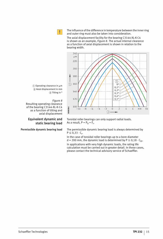
The influence of the difference in temperature between the inner ring and outer ring must also be taken into consideration.The axial displacement facility for the bearing C3144-XL-K-C4is shown as an example, Figure 8. The actual internal clearanceas a function of axial displacement is shown in relation to the bearing width.
Equivalent dynamic andstatic bearing load
Toroidal roller bearings can only support radial loads.As a result, P = P0 = Fr.
Permissible dynamic bearing load The permissible dynamic bearing load is always determined byP � 0,33 · Cr.In the case of toroidal roller bearings up to a bore diameter d = 200 mm, the dynamic load is determined by P � 0,18 · C0r.In applications with very high dynamic loads, the rating life calculation must be carried out in greater detail. In these cases, please contact the technical advisory service of Schaeffler.
� Operating clearance in �m� Axial displacement in mm
� Tilting in °
Figure 8Resulting operating clearanceof the bearing C3144-XL-K-C4
as a function of tilting andaxial displacement 00
085B
4100
085B
41

16 TPI 232 Schaeffler Technologies
Toroidal roller bearings
Minimum load In order to ensure operation without slippage, the bearings must be subjected to a minimum radial load Fr min. This applies in particular to high speed bearings since, if the radial load is insufficient ornot present, damaging sliding motion may occur between the rolling elements and raceways.The requisite minimum radial load Fr min is defined as:
Fr min kNMinimum radial loadC0 kNBasic static load rating.
If oil lubrication is used, the requisite minimum load is reducedas a function of the bearing type and speed.In order to calculate this reduction, the ancillary value kr must first be calculated as follows:
kr –Ancillary valuek� –Operating clearance factor, see dimension tabledM mmMean bearing diameter (d+D)/2.
With the aid of this ancillary value and the ratio n/nB,the requisite minimum load can be read off relative to the basic static load rating C0, Figure 9.
Fr min = minimum radial loadC0 = basic static load rating
n = speednB = reference speed
kr = ancillary value
Figure 9Minimum load with oil lubrication 00
085B
3D00
085B
3D

Schaeffler Technologies TPI 232 17
Alternatively, the requisite minimum load can also be calculated, see table.As a function of kr, the factors for calculation of the minimum load should be selected as follows:
Factors for calculationof minimum load
If kr � 340, the method cannot be used. In such cases, the equation for the requisite minimum radial load Fr min must be used.The factor for determining the influence of speed relative to the reference speed nB when using oil lubrication is defined as follows:
fn –Factor for determining the influence of speed.In the case of full complement bearings: fn = 1n min–1
SpeednB min–1
Reference speednK –Speed parameter.
The requisite minimum load is as follows:
Fr min kNMinimum radial loadfF –Factor due to influence of loadfn –Factor due to influence of speedC0 kNBasic static load rating.
Higher minimum loads may be necessary under certain conditions when starting up at low temperature, when using greases with a high base oil viscosity and where bearings have been regreased.
Ancillary value Factor due to influenceof load
Speed parameter
kr fF nK
over incl.
– 220 0,0080 1,65
220 280 0,0108 1,45
280 340 0,0135 1,25

18 TPI 232 Schaeffler Technologies
Toroidal roller bearings
Example 1 Calculation of the minimum load for the toroidal roller bearing C3144-XL-K-C4 at an operating speed of 260 min–1
with the aid of the diagram, Figure 10.
Since kr = 233 mm, the green graph in the diagram is selected. n/nB = 0,27 for Fr min/C0 = 0,0064.
For the toroidal roller bearing C3144-XL-K-C4 at C0 = 2 900 kN,the result is:
Fr min = minimum radial loadC0 = basic static load rating
n = speednB = reference speed
kr = ancillary value
Figure 10Minimum load 00
085B
C200
085B
C2

Schaeffler Technologies TPI 232 19
Example 2 Calculation of the minimum load for the toroidal roller bearing C3144-XL-K-C4 at an operating speed of 260 min–1 andoil lubrication with the aid of table, page 17.If kr �233 mm as in Example 1, this gives:
If nB · nK = 960 min–1 · 1,45 = 1392 min–1 � 260 min–1, this gives:
and
Speeds The reference speed given in the bearing tables can be exceededup to the level of the limiting speed if permitted by the operating conditions. In order to take account of special operating conditions, the thermally safe operating speed is determined, see CatalogueHR 1, Rolling Bearings.
Tolerances Bearings with a cylindrical bore and tapered bore have normal tolerances in accordance with DIN 620-2:1988 and respectively ISO 492:2014.The running accuracy for the inner ring and outer ring correspondsto the tolerance class 5.
■ nK = 1,45■ fF = 0,0108

20 TPI 232 Schaeffler Technologies
Toroidal roller bearings
Designof bearing arrangements
When designing the bearing arrangement, attention must be paid to:■ the axial location of bearings■ the fits■ the accuracy of mating parts■ free space.
Axial location of bearings In the case of toroidal roller bearings, the inner ring and outer ring must be axially located on both sides not only on the shaft but also in the housing bore. The bearing rings should therefore be mounted such that one side is in contact against a shoulder on the shaft orin the housing.The other side of the inner ring can be axially located by means of:■ a shaft nut■ a retaining ring■ a screw mounted end washer on the end of the shaft.The outer rings can normally be axially located and retained inthe housing bore by means of the cover, Figure 11.
Fits For toroidal roller bearings, the shaft and housing fits used should be on the same basis as in Catalogue HR 1, Rolling Bearings.
Accuracy of mating parts The accuracy of the cylindrical bearing seats on shafts and in housings should correspond to the accuracy of the bearings used. For toroidal roller bearings, the tolerances used should be onthe same basis as in Catalogue HR 1, Rolling Bearings, or specific recommendations for the application should be observed.
Figure 11Retention by means of retaining nut 00
0B09
3E00
0B09
3E

Schaeffler Technologies TPI 232 21
Free space Toroidal roller bearings can compensate thermally-induced changes in the length of the shaft relative to the housing within the bearing. In order to ensure the function of the bearing, free space must be provided on both end faces of the bearings, Figure 12.For bearings with a cage, the minimum values we recommendfor the depth of the free space are as follows:
Ca req mmRequisite value for the depth of the free spaceCa mmMinimum value for depth of free space in the case of bearing rings without offset, see dimension table�ax mmAxial displacement from central positions� mmReduction in axial displacement facility as a result of tilting.
In standard mounting, the bearing rings are fitted concentricallyin relation to each other. If significant changes in length occurin one direction in the application due to heat, the inner ring canbe fitted offset relative to the outer ring in the opposing directionby up to the maximum permissible axial displacement. As a result, there is a significant increase in the possible axial displacement.Toroidal roller bearings can be axially located by means of shaft nuts KML or KM and tab washers MBL-T or MB-T, Figure 11, page 20. For bearings with a bore diameter larger than 200 mm,we recommend nuts of series HM30 with retaining brackets MS30.
Figure 12Free space in housing 00
0870
5E00
0870
5E

22 TPI 232 Schaeffler Technologies
Toroidal roller bearings
In the axial location of toroidal roller bearings with retaining nuts,it must be ensured that the cage of the bearing does not grazethe retaining nut or retaining bracket if the shaft undergoes axial displacements. The outside diameter of the retaining nut should always be smaller than the mounting dimension da max given inthe dimension table.If this is not possible, an intermediate ring can be arranged between the bearing and means of retention and the thread on the shaft can be made correspondingly longer.
Mounting guidelines The mounting and dismounting of toroidal roller bearings witha cylindrical bore and of smaller bearings with a tapered boreshould be carried out in accordance with the guidelines indicatedin our Catalogue HR 1, Rolling Bearings, in the section Mountingand dismounting. For the mounting and dismounting of larger bearings on a tapered journal or sleeves, we recommend the useof the hydraulic method, see Publication MH 1, Mounting of Rolling Bearings.
Toroidal roller bearingson adapter sleeve or
withdrawal sleeve
Toroidal roller bearings with a tapered bore can be mounted on smooth or stepped shafts by means of an adapter sleeve or with-drawal sleeve, Figure 13. In the case of substantial axial displace-ments, it must be ensured that the axial displacement always occurs in the direction of the sleeve nut. The Schaeffler adapter sleeves have been adapted specially for the TORB bearings in order to fulfil the particular requirements of these designs. For TORB bearings, please use adapter sleeves with the suffix T, for example H24026-T.For general information on the mounting of rolling bearingson adapter sleeves and withdrawal sleeves, see Catalogue HR 1,Rolling Bearings.
Figure 13Toroidal roller bearing
on adapter sleeve 000A
866E
000A
866E

Schaeffler Technologies TPI 232 23

Toroidal roller bearings
24 TPI 232 Schaeffler Technologies
Reduced radial internal clearancein mounting
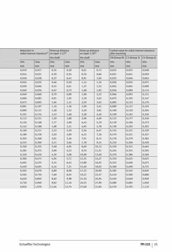
When bearings with a tapered bore are mounted, there isa reduction in the radial internal clearance.The values indicated values ensure a secure seat on the shaft,see table.
Reductionin radial internal clearance
of FAG toroidal roller bearingswith tapered bore
1) Valid only for solid steel shafts and hollow shafts with a bore no largerthan half the shaft diameter.The following applies: Bearings with a radial internal clearance beforemounting in the upper half of the tolerance range are mounted usingthe larger value for the reduction in radial internal clearance or the axialdisplacement distance, while bearings in the lower half of the tolerancerange are mounted using the smaller value for the reduction in radialinternal clearance or the axial displacement distance.
Nominal bearing bore diameter
Radial internal clearance before mountingInternal clearance group
d CN (Group N) C3 (Group 3) C4 (Group 4)
over incl. min. max. min. max. min. max.
mm mm mm mm mm mm mm mm
24 30 0,035 0,055 0,050 0,065 0,065 0,085
30 40 0,045 0,065 0,060 0,080 0,080 0,100
40 50 0,050 0,075 0,070 0,095 0,090 0,120
50 65 0,060 0,090 0,085 0,115 0,110 0,150
65 80 0,075 0,110 0,105 0,140 0,135 0,180
80 100 0,095 0,135 0,130 0,175 0,170 0,220
100 120 0,115 0,155 0,155 0,205 0,200 0,255
120 140 0,135 0,180 0,180 0,235 0,230 0,295
140 160 0,155 0,215 0,210 0,270 0,265 0,340
160 180 0,170 0,240 0,235 0,305 0,300 0,385
180 200 0,190 0,260 0,260 0,330 0,325 0,420
200 225 0,210 0,290 0,285 0,365 0,360 0,460
225 250 0,235 0,315 0,315 0,405 0,400 0,515
250 280 0,255 0,345 0,340 0,445 0,440 0,560
280 315 0,280 0,380 0,375 0,485 0,480 0,620
315 355 0,315 0,420 0,415 0,545 0,540 0,680
355 400 0,350 0,475 0,470 0,600 0,595 0,755
400 450 0,380 0,525 0,525 0,655 0,650 0,835
450 500 0,435 0,575 0,575 0,735 0,730 0,915
500 560 0,470 0,640 0,630 0,810 0,800 1,010
560 630 0,530 0,710 0,700 0,890 0,880 1,110
630 710 0,590 0,780 0,770 0,990 0,980 1,230
710 800 0,670 0,860 0,860 1,100 1,100 1,380
800 900 0,730 0,960 0,950 1,220 1,210 1,530
900 1 000 0,810 1,040 1,040 1,340 1,340 1,670
1 000 1 120 0,890 1,170 1,160 1,500 1,490 1,880
1 120 1 250 0,970 1,280 1,270 1,640 1,630 2,060
1 250 1 400 1,080 1,410 1,410 1,790 1,780 2,250
1 400 1 600 1,200 1,550 1,550 1,990 1,990 2,500
1 600 1 800 1,320 1,690 1,690 2,180 2,180 2,730
Schaeffler Technologies TPI 232 25
Reduction inradial internal clearance1)
Drive-up distanceon taper 1:121)
Drive-up distanceon taper 1:301)
Control value for radial internal clearance after mounting
the shaft the shaft CN (Group N) C3 (Group 3) C4 (Group 4)
min. max. min. max. min. max. min. min. min.
mm mm mm mm mm mm mm mm mm
0,010 0,017 0,24 0,29 0,61 0,72 0,025 0,035 0,048
0,014 0,021 0,30 0,34 0,76 0,84 0,031 0,041 0,059
0,018 0,028 0,37 0,42 0,91 1,04 0,033 0,046 0,062
0,024 0,035 0,46 0,50 1,14 1,24 0,036 0,054 0,075
0,030 0,046 0,55 0,61 1,37 1,53 0,045 0,065 0,090
0,040 0,056 0,67 0,73 1,68 1,83 0,056 0,080 0,114
0,049 0,069 0,79 0,89 1,98 2,23 0,066 0,093 0,131
0,060 0,083 0,91 1,05 2,29 2,62 0,075 0,105 0,147
0,072 0,095 1,04 1,21 2,59 3,02 0,083 0,123 0,170
0,081 0,107 1,16 1,36 2,90 3,41 0,089 0,137 0,193
0,090 0,121 1,28 1,52 3,20 3,81 0,100 0,150 0,204
0,101 0,134 1,43 1,68 3,58 4,20 0,109 0,162 0,226
0,113 0,151 1,59 1,88 3,96 4,69 0,123 0,177 0,249
0,126 0,168 1,77 2,08 4,42 5,19 0,129 0,186 0,273
0,142 0,188 1,98 2,31 4,95 5,78 0,138 0,203 0,292
0,160 0,211 2,23 2,59 5,56 6,47 0,155 0,221 0,329
0,180 0,238 2,50 2,90 6,25 7,26 0,170 0,251 0,357
0,203 0,268 2,81 3,26 7,01 8,15 0,178 0,279 0,382
0,225 0,300 3,11 3,66 7,78 9,14 0,210 0,300 0,430
0,250 0,335 3,48 4,05 8,69 10,13 0,220 0,325 0,465
0,285 0,375 3,90 4,52 9,76 11,31 0,245 0,355 0,505
0,320 0,420 4,39 5,08 10,98 12,69 0,270 0,380 0,560
0,360 0,475 4,94 5,71 12,35 14,27 0,310 0,425 0,625
0,405 0,535 5,55 6,42 13,88 16,05 0,325 0,460 0,675
0,450 0,605 6,16 7,21 15,40 18,03 0,360 0,490 0,735
0,505 0,670 6,89 8,00 17,23 20,00 0,385 0,545 0,820
0,565 0,750 7,69 8,95 19,21 22,37 0,410 0,580 0,880
0,630 0,840 8,60 9,98 21,50 24,94 0,450 0,640 0,940
0,720 0,940 9,82 11,16 24,55 27,90 0,480 0,685 1,050
0,810 1,070 11,04 12,74 27,60 31,85 0,510 0,705 1,110

26 TPI 232 Schaeffler Technologies
Toroidal roller bearings
Accuracy The main dimensions of the toroidal roller bearings listedin the dimension tables match the data in DIN 616:1994 and ISO 15:1981 respectively.
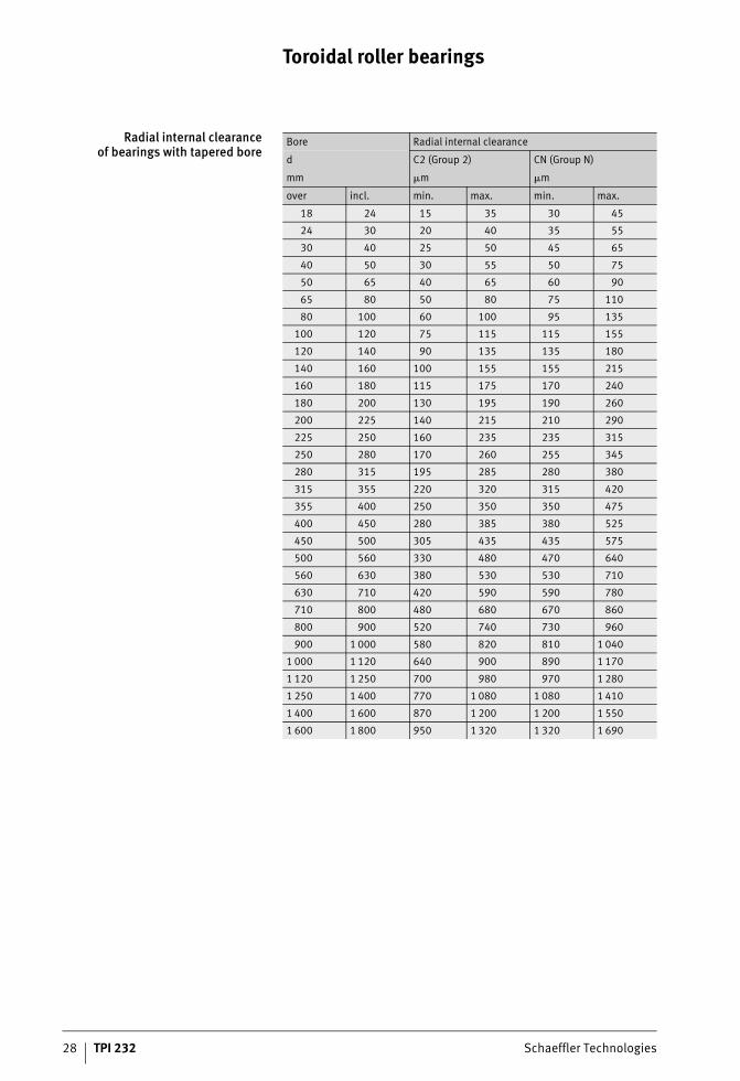
Radial internal clearance The values for the radial internal clearance of bearings witha cylindrical bore, see table, and those for bearings with a tapered bore, see table, page 28, are valid for unmounted bearings witha measurement load of zero.Axial displacements of the bearing rings relative to each otherwill reduce the internal clearance of toroidal roller bearings.This reduction can be determined, see page 13.
Radial internal clearanceof bearings with cylindrical bore
Hole Radial internal clearance
d C2 (Group 2) CN (Group N)
mm �m �m
over incl. min. max. min. max.
18 24 15 30 25 40
24 30 15 35 30 50
30 40 20 40 35 55
40 50 25 45 45 65
50 65 30 55 50 80
65 80 40 70 65 100
80 100 50 85 80 120
100 120 60 100 100 145
120 140 75 120 115 170
140 160 85 140 135 195
160 180 95 155 150 220
180 200 105 175 170 240
200 225 115 190 185 265
225 250 125 205 200 285
250 280 135 225 220 310
280 315 150 240 235 330
315 355 160 260 255 360
355 400 175 280 280 395
400 450 190 310 305 435
450 500 205 335 335 475
500 560 220 360 360 520
560 630 240 400 390 570
630 710 260 440 430 620
710 800 300 500 490 680
800 900 320 540 530 760
900 1 000 370 600 590 830
1 000 1 120 410 660 660 930
1 120 1 250 450 720 720 1 020
1 250 1 400 490 800 800 1 130
1 400 1 600 570 890 890 1 250
1 600 1 800 650 1 010 1 010 1 390

Schaeffler Technologies TPI 232 27
Radial internal clearanceof bearings with cylindrical bore
(continued)
Bore Radial internal clearance
d C3 (Group 3) C4 (Group 4) C5 (Group 5)
mm �m �m �m
over incl. min. max. min. max. min. max.
18 24 35 55 50 65 65 85
24 30 45 60 60 80 75 95
30 40 55 75 70 95 90 120
40 50 65 85 85 110 105 140
50 65 75 105 100 140 135 175
65 80 95 125 120 165 160 210
80 100 120 160 155 210 205 260
100 120 140 190 185 245 240 310
120 140 165 215 215 280 280 350
140 160 195 250 250 325 320 400
160 180 215 280 280 365 360 450
180 200 235 310 305 395 390 495
200 225 260 340 335 435 430 545
225 250 280 370 365 480 475 605
250 280 305 410 405 520 515 655
280 315 330 435 430 570 570 715
315 355 360 485 480 620 620 790
355 400 395 530 525 675 675 850
400 450 435 580 575 745 745 930
450 500 475 635 630 815 810 1 015
500 560 510 690 680 890 890 1 110
560 630 560 760 750 980 970 1 220
630 710 610 840 830 1 080 1 070 1 340
710 800 680 920 920 1 200 1 200 1 480
800 900 750 1 020 1 010 1 330 1 320 1 660
900 1 000 830 1 120 1 120 1 460 1 460 1 830
1 000 1 120 930 1 260 1 260 1 640 1 640 2 040
1 120 1 250 1 020 1 380 1 380 1 800 1 800 2 240
1 250 1 400 1 130 1 510 1 540 1 970 1 970 2 460
1 400 1 600 1 250 1 680 1 680 2 200 2 200 2 740
1 600 1 800 1 390 1 870 1 870 2 430 2 430 3 000
28 TPI 232 Schaeffler Technologies
Toroidal roller bearings
Radial internal clearanceof bearings with tapered bore
Bore Radial internal clearance
d C2 (Group 2) CN (Group N)
mm �m �m
over incl. min. max. min. max.
18 24 15 35 30 45
24 30 20 40 35 55
30 40 25 50 45 65
40 50 30 55 50 75
50 65 40 65 60 90
65 80 50 80 75 110
80 100 60 100 95 135
100 120 75 115 115 155
120 140 90 135 135 180
140 160 100 155 155 215
160 180 115 175 170 240
180 200 130 195 190 260
200 225 140 215 210 290
225 250 160 235 235 315
250 280 170 260 255 345
280 315 195 285 280 380
315 355 220 320 315 420
355 400 250 350 350 475
400 450 280 385 380 525
450 500 305 435 435 575
500 560 330 480 470 640
560 630 380 530 530 710
630 710 420 590 590 780
710 800 480 680 670 860
800 900 520 740 730 960
900 1 000 580 820 810 1 040
1 000 1 120 640 900 890 1 170
1 120 1 250 700 980 970 1 280
1 250 1 400 770 1 080 1 080 1 410
1 400 1 600 870 1 200 1 200 1 550
1 600 1 800 950 1 320 1 320 1 690

Schaeffler Technologies TPI 232 29
Radial internal clearanceof bearings with tapered bore
(continued)
Bore Radial internal clearance
d C3 (Group 3) C4 (Group 4) C5 (Group 5)
mm �m �m �m
over incl. min. max. min. max. min. max.
18 24 40 55 55 70 65 85
24 30 50 65 65 85 80 100
30 40 60 80 80 100 100 125
40 50 70 95 90 120 115 145
50 65 85 115 110 150 145 185
65 80 105 140 135 180 175 220
80 100 130 175 170 220 215 275
100 120 155 205 200 255 255 325
120 140 180 235 230 295 290 365
140 160 210 270 265 340 335 415
160 180 235 305 300 385 380 470
180 200 260 330 325 420 415 520
200 225 285 365 360 460 460 575
225 250 315 405 400 515 510 635
250 280 340 445 440 560 555 695
280 315 375 485 480 620 615 765
315 355 415 545 540 680 675 850
355 400 470 600 595 755 755 920
400 450 525 655 650 835 835 1 005
450 500 575 735 730 915 910 1 115
500 560 630 810 800 1 010 1 000 1 230
560 630 700 890 880 1 110 1 110 1 350
630 710 770 990 980 1 230 1 230 1 490
710 800 860 1 100 1 100 1 380 1 380 1 660
800 900 950 1 220 1 210 1 530 1 520 1 860
900 1 000 1 040 1 340 1 340 1 670 1 670 2 050
1 000 1 120 1 160 1 500 1 490 1 880 1 870 2 280
1 120 1 250 1 270 1 640 1 630 2 060 2 050 2 500
1 250 1 400 1 410 1 790 1 780 2 250 2 250 2 740
1 400 1 600 1 550 1 990 1 990 2 500 2 500 3 050
1 600 1 800 1 690 2 180 2 180 2 730 2 730 3 310
30 TPI 232 Schaeffler Technologies
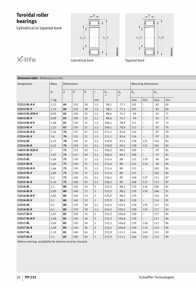
Toroidal roller bearingsCylindrical or tapered bore
Cylindrical bore Tapered bore
0008
1E29
0008
1E29
0008
1E41
0008
1E41
Before ordering, availability for delivery must be checked.
Dimension table · Dimensions in mm
Designation Mass Dimensions Mounting dimensions
m d D B r D1�
d2�
Da da
� kg min. max. min. max. min.
C2212-XL-K-V 1,12 60 110 28 1,5 98,1 77,1 101 – 85 69
C2212-XL-V 1,15 60 110 28 1,5 98,1 77,1 101 – 85 69
C4013-XL-K30-V 0,95 65 100 35 1,1 88,6 74,7 94 – 82 71
C4013-XL-V 0,98 65 100 35 1,1 88,6 74,7 94 – 82 71
C2213-XL-K-V 1,48 65 120 31 1,5 106,1 78,9 111 – 97 74
C2213-XL-V 1,52 65 120 31 1,5 106,1 78,9 111 – 97 74
C2214-XL-K-V 1,56 70 125 31 1,5 111,1 83,6 116 – 97 79
C2214-XL-V 1,6 70 125 31 1,5 111,1 83,6 116 – 97 79
C2314-XL 4,33 70 150 51 2,1 130,9 92,5 138 121 105 82
C2314-XL-K 4,22 70 150 51 2,1 130,9 92,5 138 121 105 82
C4015-XL-K30-V 1 75 115 40 1,1 100,2 89,5 109 – 97 81
C4015-XL-V 1,47 75 115 40 1,1 100,2 89,5 109 – 97 81
C2215-XL 1,69 75 130 31 1,5 115,4 88 121 110 96 84
C2215-XL-K 1,64 75 130 31 1,5 115,4 88 121 110 96 84
C2215-XL-K-V 1,64 75 130 31 1,5 115,4 88 121 – 102 84
C2215-XL-V 1,69 75 130 31 1,5 115,4 88 121 – 102 84
C2315-XL 5,3 75 160 55 2,1 136,5 99 148 127 111 87
C2315-XL-K 5,16 75 160 55 2,1 136,5 99 148 127 111 87
C2216-XL 2,1 80 140 33 2 125,5 98,2 129 120 106 91
C2216-XL-K 2,05 80 140 33 2 125,5 98,2 129 120 106 91
C2216-XL-K-V 2,05 80 140 33 2 125,5 98,2 129 – 116 91
C2216-XL-V 2,1 80 140 33 2 125,5 98,2 129 – 116 91
C2316-XL 6,3 80 170 58 2,1 145,5 103,5 158 135 117 92
C2316-XL-K 6,1 80 170 58 2,1 145,5 103,5 158 135 117 92
C2217-XL-V 2,65 85 150 36 2 132,2 104,8 139 – 117 96
C2217-XL-K-V 2,58 85 150 36 2 132,2 104,8 139 – 117 96
C2217-XL 2,65 85 150 36 2 132,2 104,8 139 126 113 96
C2217-XL-K 2,58 85 150 36 2 132,2 104,8 139 126 113 96
C2317-XL 7,29 85 180 60 3 153,9 111,1 166 143 125 99
C2317-XL-K 7,1 85 180 60 3 153,9 111,1 166 143 125 99

Schaeffler Technologies TPI 232 31
Displacement distance Mounting dimensions
0009
7F36
0009
7F36
0008
1EB4
0008
1EB4
Basic load ratings Calculation factors Fatiguelimit load
Limitingspeed
Referencespeed
Ca ra s1 s2 dyn.C
stat.C0
k� k� Cu nG nB
min. max. N N N min–1 min–1
– 1,5 8,5 5,3 171 000 195 000 3,116 3,713 32 500 2 650 –
– 1,5 8,5 5,3 171 000 195 000 3,116 3,713 32 500 2 650 –
– 1 6 2,8 197 000 285 000 3,543 3,082 33 500 3 050 –
– 1 6 2,8 197 000 285 000 3,543 3,082 33 500 3 050 –
– 1,5 9,6 5,3 208 000 216 000 3,298 3,505 36 000 2 340 –
– 1,5 9,6 5,3 208 000 216 000 3,298 3,505 36 000 2 340 –
– 1,5 9,6 5,3 215 000 229 000 3,523 3,265 38 000 2 180 –
– 1,5 9,6 5,3 215 000 229 000 3,523 3,265 38 000 2 180 –
1,6 2 9,1 – 405 000 440 000 5,477 1,941 52 000 6 000 3 200
1,6 2 9,1 – 405 000 440 000 5,477 1,941 52 000 6 000 3 200
– 1 9,4 5,1 209 000 355 000 3,893 2,845 39 500 2 470 –
– 1 9,4 5,1 209 000 355 000 3,893 2,845 39 500 2 470 –
1,11 1,5 9,6 – 197 000 207 000 3,56 3,268 33 000 7 000 3 250
1,11 1,5 9,6 – 197 000 207 000 3,56 3,268 33 000 7 000 3 250
– 1,5 9,6 5,3 221 000 241 000 3,56 3,268 38 500 2 050 –
– 1,5 9,6 5,3 221 000 241 000 3,56 3,268 38 500 2 050 –
1,5 2 13,1 – 430 000 470 000 5,53 1,941 56 000 5 600 3 200
1,5 2 13,1 – 430 000 470 000 5,53 1,941 56 000 5 600 3 200
1,1 2 9,1 – 224 000 250 000 3,889 2,997 41 000 6 300 2 900
1,1 2 9,1 – 224 000 250 000 3,889 2,997 41 000 6 300 2 900
– 2 9,1 4,8 260 000 305 000 3,889 2,997 49 500 1 790 –
– 2 9,1 4,8 260 000 305 000 3,889 2,997 49 500 1 790 –
1,7 2 10,1 – 510 000 550 000 6,094 1,745 62 000 5 100 3 050
1,7 2 10,1 – 510 000 550 000 6,094 1,745 62 000 5 100 3 050
– 2 7,1 1,7 315 000 395 000 4,194 2,763 59 000 1 640 –
– 2 7,1 1,7 315 000 395 000 4,194 2,763 59 000 1 640 –
1,1 2 7,1 – 275 000 330 000 4,194 2,763 49 000 5 900 2 750
1,1 2 7,1 – 275 000 330 000 4,194 2,763 49 000 5 900 2 750
1,72 2,5 12,1 – 550 000 610 000 6,144 1,752 68 000 4 800 2 850
1,72 2,5 12,1 – 550 000 610 000 6,144 1,752 68 000 4 800 2 850

32 TPI 232 Schaeffler Technologies
Toroidal roller bearingsCylindrical or tapered bore
Cylindrical bore Tapered bore
0008
1E29
0008
1E29
0008
1E41
0008
1E41
Before ordering, availability for delivery must be checked.
Dimension table (continued) · Dimensions in mm
Designation Mass Dimensions Mounting dimensions
m d D B r D1�
d2�
Da da
� kg min. max. min. max. min.
C2218-XL-K 3,29 90 160 40 2 143,9 112,1 149 137 122 101
C2218-XL 3,38 90 160 40 2 143,9 112,1 149 137 122 101
C2318-XL-K 8,4 90 190 64 3 167,4 119,6 176 154 136 104
C2318-XL 8,65 90 190 64 3 167,4 119,6 176 154 136 104
C2219-XL-K 4,01 95 170 43 2,1 149,7 112,3 158 140 125 107
C2219-XL 4,12 95 170 43 2,1 149,7 112,3 158 140 125 107
C2319-XL-K 9,75 95 200 67 3 167,6 120,4 186 155 137 109
C2319-XL 10 95 200 67 3 167,6 120,4 186 155 137 109
C4020-XL-K30-V 2,94 100 150 50 1,5 133,6 113,6 141 – 125 109
C4020-XL-V 3,02 100 150 50 1,5 133,6 113,6 141 – 125 109
C3120-XL-K-V 4,21 100 165 52 2 150,7 119,7 154 – 132 111
C3120-XL-V 4,32 100 165 52 2 150,7 119,7 154 – 132 111
C4120-XL-K30-V 5,26 100 165 65 2 147,4 120,6 154 – 132 111
C4120-XL-V 5,4 100 165 65 2 147,4 120,6 154 – 132 111
C2220-XL 4,97 100 180 46 2,1 156,9 118,1 168 147 131 112
C2220-XL-K 4,84 100 180 46 2,1 156,9 118,1 168 147 131 112
C2320-XL-K 12,4 100 215 73 3 184 129 201 169 148 114
C2320-XL 12,8 100 215 73 3 184 129 201 169 148 114
C3022-XL 3,65 110 170 45 2 156,2 127,8 161 151 136 119
C3022-XL-K 3,55 110 170 45 2 156,2 127,8 161 151 136 119
C4022-XL-K30-V 4,74 110 170 60 2 151,2 127,2 160 – 140 120
C4022-XL-V 4,86 110 170 60 2 151,2 127,2 160 – 140 120
C4122-XL-K30-V 6,58 110 180 69 2 163 132,7 170 – 145 120
C4122-XL-V 6,76 110 180 69 2 163 132,7 170 – 145 120
C2222-XL 7,14 110 200 53 2,1 178,5 135,9 188 168 150 122
C2222-XL-K 6,95 110 200 53 2,1 178,5 135,9 188 168 150 122

Schaeffler Technologies TPI 232 33
Displacement distance Mounting dimensions
0009
7F36
0009
7F36
0008
1EB4
0008
1EB4
Basic load ratings Calculation factors Fatiguelimit load
Limitingspeed
Referencespeed
Ca ra s1 s2 dyn.C
stat.C0
k� k� Cu nG nB
min. max. N N N min–1 min–1
1,3 2 9,5 – 330 000 380 000 4,103 2,924 55 000 5 300 2 650
1,3 2 9,5 – 330 000 380 000 4,103 2,924 55 000 5 300 2 650
1,9 2,5 9,6 – 650 000 740 000 6,754 1,589 77 000 4 350 2 500
1,9 2,5 9,6 – 650 000 740 000 6,754 1,589 77 000 4 350 2 500
1,5 2 10,5 – 370 000 405 000 4,75 2,42 61 000 5 000 2 750
1,5 2 10,5 – 370 000 405 000 4,75 2,42 61 000 5 000 2 750
1,9 2,5 12,6 – 660 000 750 000 6,758 1,589 78 000 4 350 2 600
1,9 2,5 12,6 – 660 000 750 000 6,758 1,589 78 000 4 350 2 600
– 1,5 14 9,7 355 000 530 000 4,766 2,365 66 000 1 580 –
– 1,5 14 9,7 355 000 530 000 4,766 2,365 66 000 1 580 –
– 2 10 4,7 490 000 660 000 6,699 1,582 86 000 1 330 –
– 2 10 4,7 490 000 660 000 6,699 1,582 86 000 1 330 –
– 2 17,7 5,2 530 000 730 000 5,69 1,929 83 000 1 350 –
– 2 17,7 5,2 530 000 730 000 5,69 1,929 83 000 1 350 –
1,6 2 10,1 – 420 000 470 000 4,849 2,393 68 000 4 700 2 700
1,6 2 10,1 – 420 000 470 000 4,849 2,393 68 000 4 700 2 700
2,2 2,5 11,2 – 820 000 920 000 8,026 1,312 97 000 3 850 2 290
2,2 2,5 11,2 – 820 000 920 000 8,026 1,312 97 000 3 850 2 290
1,8 2 9,5 – 360 000 480 000 5,707 1,954 63 000 4 800 2 480
1,8 2 9,5 – 360 000 480 000 5,707 1,954 63 000 4 800 2 480
– 2 12 6,6 510 000 800 000 6,296 1,717 89 000 1 320 –
– 2 12 6,6 510 000 800 000 6,296 1,717 89 000 1 320 –
– 2 11,4 4,6 680 000 1 000 000 6,99 1,529 104 000 1 160 –
– 2 11,4 4,6 680 000 1 000 000 6,99 1,529 104 000 1 160 –
2 2 11,1 – 550 000 650 000 5,866 1,941 89 000 4 050 2 330
2 2 11,1 – 550 000 650 000 5,866 1,941 89 000 4 050 2 330

34 TPI 232 Schaeffler Technologies
Toroidal roller bearingsCylindrical or tapered bore
Cylindrical bore Tapered bore
0008
1E29
0008
1E29
0008
1E41
0008
1E41
Before ordering, availability for delivery must be checked.
Dimension table (continued) · Dimensions in mm
Designation Mass Dimensions Mounting dimensions
m d D B r D1�
d2�
Da da
� kg min. max. min. max. min.
C3024-XL-V 4 120 180 46 2 166 138 171 – 150 129
C3024-XL-K-V 3,88 120 180 46 2 166 138 171 – 150 129
C3024-XL 4 120 180 46 2 165,5 137,9 171 161 150 129
C3024-XL-K 3,89 120 180 46 2 165,5 137,9 171 161 150 129
C4024-XL-K30-V 5,08 120 180 60 2 165,6 141,6 171 – 150 129
C4024-XL-V 5,2 120 180 60 2 165,6 141,6 171 – 150 129
C4124-XL-K30-V 9,63 120 200 80 2 174 142 189 – 160 131
C4124-XL-V 9,88 120 200 80 2 174 142 189 – 160 131
C2224-XL 8,91 120 215 58 2,1 190,2 144,8 203 178 160 132
C2224-XL-K 8,68 120 215 58 2,1 190,2 144,8 203 178 160 132
C3224-XL-K 11,3 120 215 76 2,1 190 149 203 180 162 132
C3224-XL 11,7 120 215 76 2,1 190 149 203 180 162 132
C3026-XL-K 5,63 130 200 52 2 179,9 154,1 191 176 161 139
C3026-XL 5,8 130 200 52 2 179,9 154,1 191 176 161 139
C4026-XL-K30-V 7,49 130 200 69 2 179,8 150,2 191 – 165 139
C4026-XL-V 7,69 130 200 69 2 179,8 150,2 191 – 165 139
C4126-XL-K30-V 10,2 130 210 80 2 188,4 154,6 199 – 170 141
C4126-XL-V 10,5 130 210 80 2 188,4 154,6 199 – 170 141
C2226-XL 11,1 130 230 64 3 199,3 151,7 216 188 167 144
C2226-XL-K 10,8 130 230 64 3 199,3 151,7 216 188 167 144
C2326-XL 27,6 130 280 93 4 236 179 263 – 205 147
C2326-XL-K 26,9 130 280 93 4 236 179 263 – 205 147
C3028-XL-K 6,1 140 210 53 2 193,9 163,1 201 188 172 149
C3028-XL 6,27 140 210 53 2 193,9 163,1 201 188 172 149
C4028-XL-V 8,16 140 210 69 2 191,1 161,5 201 – 175 149
C4028-XL-K30-V 7,95 140 210 69 2 191,1 161,5 201 – 175 149
C4128-XL-K30-V 12,4 140 225 85 2,1 203,2 166,8 214 – 182 151
C4128-XL-V 12,7 140 225 85 2,1 203,2 166,8 214 – 182 151
C2228-XL 14,1 140 250 68 3 221,4 174,6 236 210 190 154
C2228-XL-K 13,7 140 250 68 3 221,4 174,6 236 210 190 154

Schaeffler Technologies TPI 232 35
Displacement distance Mounting dimensions
0009
7F36
0009
7F36
0008
1EB4
0008
1EB4
Basic load ratings Calculation factors Fatiguelimit load
Limitingspeed
Referencespeed
Ca ra s1 s2 dyn.C
stat.C0
k� k� Cu nG nB
min. max. N N N min–1 min–1
– 2 10,6 3,8 435 000 630 000 6,176 1,799 81 000 1 140 –
– 2 10,6 3,8 435 000 630 000 6,176 1,799 81 000 1 140 –
1,7 2 10,6 – 390 000 550 000 6,176 1,799 70 000 4 450 2 290
1,7 2 10,6 – 390 000 550 000 6,176 1,799 70 000 4 450 2 290
– 2 12 5,2 550 000 890 000 6,421 1,717 99 000 1 120 –
– 2 12 5,2 550 000 890 000 6,421 1,717 99 000 1 120 –
– 2 18 11,2 780 000 1 140 000 7,458 1,435 124 000 1 030 –
– 2 18 11,2 780 000 1 140 000 7,458 1,435 124 000 1 030 –
1,9 2 13 – 630 000 740 000 6,372 1,778 101 000 3 700 2 200
1,9 2 13 – 630 000 740 000 6,372 1,778 101 000 3 700 2 200
1,5 2 17,1 – 760 000 1 000 000 7,65 1,423 92 000 3 700 1 960
1,5 2 17,1 – 760 000 1 000 000 7,65 1,423 92 000 3 700 1 960
0,8 2 16,5 – 405 000 600 000 6,777 1,641 74 000 4 000 2 210
0,8 2 16,5 – 405 000 600 000 6,777 1,641 74 000 4 000 2 210
– 2 11,4 4,6 730 000 1 130 000 7,137 1,531 119 000 990 –
– 2 11,4 4,6 730 000 1 130 000 7,137 1,531 119 000 990 –
– 2 18 9,7 840 000 1 240 000 7,568 1,437 129 000 910 –
– 2 18 9,7 840 000 1 240 000 7,568 1,437 129 000 910 –
2 2,5 9,6 – 760 000 970 000 6,983 1,602 119 000 3 550 2 040
2 2,5 9,6 – 760 000 970 000 6,983 1,602 119 000 3 550 2 040
2,12 3 31,2 – 1 040 000 1 270 000 9,001 1,216 135 000 2 800 1 710
2,12 3 31,2 – 1 040 000 1 270 000 9,001 1,216 135 000 2 800 1 710
1 2 11 – 495 000 730 000 7,08 1,581 88 000 3 650 1 940
1 2 11 – 495 000 730 000 7,08 1,581 88 000 3 650 1 940
– 2 11,4 5,9 760 000 1 220 000 7,235 1,531 126 000 890 –
– 2 11,4 5,9 760 000 1 220 000 7,235 1,531 126 000 890 –
– 2 12 5,2 1 020 000 1 590 000 9,241 1,144 157 000 810 –
– 2 12 5,2 1 020 000 1 590 000 9,241 1,144 157 000 810 –
1,9 2,5 13,7 – 830 000 1 080 000 7,191 1,598 126 000 3 050 1 750
1,9 2,5 13,7 – 830 000 1 080 000 7,191 1,598 126 000 3 050 1 750

36 TPI 232 Schaeffler Technologies
Toroidal roller bearingsCylindrical or tapered bore
Cylindrical bore Tapered bore
0008
1E29
0008
1E29
0008
1E41
0008
1E41
Before ordering, availability for delivery must be checked.
Dimension table (continued) · Dimensions in mm
Designation Mass Dimensions Mounting dimensions
m d D B r D1�
d2�
Da da
� kg min. max. min. max. min.
C3030-XL-V 7,6 150 225 56 2,1 204,1 173,9 214 – 187 161
C3030-XL-K-M1B 7,4 150 225 56 2,1 204,1 173,9 214 199 172,2 161
C3030-XL-K-V 7,4 150 225 56 2,1 204,1 173,9 214 – 187 161
C3030-XL-M1B 7,6 150 225 56 2,1 204,1 173,9 214 199 172,2 161
C4030-XL-K30-V 9,91 150 225 75 2,1 202,2 173,8 214 – 187 161
C4030-XL-V 10,2 150 225 75 2,1 202,2 173,8 214 – 187 161
C3130-XL-K 15 150 250 80 2,1 225,5 182,5 238 215 197 162
C3130-XL 15,4 150 250 80 2,1 225,5 182,5 238 215 197 162
C4130-XL-K30-V 18,8 150 250 100 2,1 221,5 179,5 228 – 200 162
C4130-XL-V 19,3 150 250 100 2,1 221,5 179,5 228 – 200 162
C2230-XL 17,8 150 270 73 3 235,8 177,2 256 220 197 164
C2230-XL-K 17,3 150 270 73 3 235,8 177,2 256 220 197 164
C3032-XL 9,26 160 240 60 2,1 218,1 186,9 229 212 196 171
C3032-XL-K 9 160 240 60 2,1 218,1 186,9 229 212 196 171
C4032-XL-K30-V 12 160 240 80 2,1 215,7 182,3 229 – 200 171
C4032-XL-V 12,4 160 240 80 2,1 215,7 182,3 229 – 200 171
C3132-XL-K-M1B 19,1 160 270 86 2,1 238,2 191,8 258 227 189 172
C3132-XL-M1B 19,6 160 270 86 2,1 238,2 191,8 258 227 189 172
C4132-XL-K30-V 24,2 160 270 109 2,1 239 192 258 – 215 172
C4132-XL-V 24,9 160 270 109 2,1 239 192 258 – 215 172
C3232-XL 29,4 160 290 104 3 255,2 194,8 276 239 216 174
C3232-XL-K 28,5 160 290 104 3 255,2 194,8 276 239 216 174
C3034-XL 12,5 170 260 67 2,1 236,1 200,9 249 229 211 181
C3034-XL-K 12,2 170 260 67 2,1 236,1 200,9 249 229 211 181
C4034-XL-K30-V 16,4 170 260 90 2,1 233,7 196,3 249 – 222 181
C4034-XL-V 16,8 170 260 90 2,1 233,7 196,3 249 – 222 181
C3134-XL-K 20,5 170 280 88 2,1 248 201 268 237 216 182
C3134-XL 21 170 280 88 2,1 248 201 268 237 216 182
C4134-XL-K30-V 25,4 170 280 109 2,1 250,5 200,5 268 – 225 182
C4134-XL-V 26 170 280 109 2,1 250,5 200,5 268 – 225 182
C2234-XL 27,9 170 310 86 4 273,8 209,2 293 257 231 187
C2234-XL-K 27,1 170 310 86 4 273,8 209,2 293 257 231 187

Schaeffler Technologies TPI 232 37
Displacement distance Mounting dimensions
0009
7F36
0009
7F36
0008
1EB4
0008
1EB4
Basic load ratings Calculation factors Fatiguelimit load
Limitingspeed
Referencespeed
Ca ra s1 s2 dyn.C
stat.C0
k� k� Cu nG nB
min. max. N N N min–1 min–1
– 2 14,1 7,3 600 000 960 000 7,535 1,483 114 000 810 –
1,16 2 8,7 – 540 000 850 000 7,535 1,483 101 000 3 400 1 790
– 2 14,1 7,3 600 000 960 000 7,535 1,483 114 000 810 –
1,16 2 8,7 – 540 000 850 000 7,535 1,483 101 000 3 400 1 790
– 2 17,4 10,6 780 000 1 320 000 7,338 1,531 132 000 810 –
– 2 17,4 10,6 780 000 1 320 000 7,338 1,531 132 000 810 –
0,9 2 13,9 – 920 000 1 310 000 9,371 1,15 139 000 3 000 1 610
0,9 2 13,9 – 920 000 1 310 000 9,371 1,15 139 000 3 000 1 610
– 2 20 10,1 1 240 000 1 880 000 10,222 1,03 186 000 710 –
– 2 20 10,1 1 240 000 1 880 000 10,222 1,03 186 000 710 –
2,4 2,5 11,2 – 1 010 000 1 240 000 8,45 1,313 152 000 2 850 1 680
2,4 2,5 11,2 – 1 010 000 1 240 000 8,45 1,313 152 000 2 850 1 680
0,8 2 15 – 610 000 980 000 8,127 1,373 116 000 3 150 1 640
0,8 2 15 – 610 000 980 000 8,127 1,373 116 000 3 150 1 640
– 2 18,1 8,2 910 000 1 470 000 8,521 1,286 158 000 740 –
– 2 18,1 8,2 910 000 1 470 000 8,521 1,286 158 000 740 –
1,73 2 10,3 – 1 010 000 1 410 000 9,469 1,15 147 000 2 800 1 550
1,73 2 10,3 – 1 010 000 1 410 000 9,469 1,15 147 000 2 800 1 550
– 2 21 11,1 1 470 000 2 200 000 10,886 0,969 211 000 630 –
– 2 21 11,1 1 470 000 2 200 000 10,886 0,969 211 000 630 –
2,4 2,5 19,3 – 1 440 000 1 870 000 11,556 0,915 224 000 2 550 1 340
2,4 2,5 19,3 – 1 440 000 1 870 000 11,556 0,915 224 000 2 550 1 340
0,9 2 12,5 – 770 000 1 200 000 7,129 1,672 114 000 2 850 1 480
0,9 2 12,5 – 770 000 1 200 000 7,129 1,672 114 000 2 850 1 480
– 2 17,1 7,2 1 140 000 1 880 000 9,496 1,145 187 000 650 –
– 2 17,1 7,2 1 140 000 1 880 000 9,496 1,145 187 000 650 –
1,7 2 21 – 1 060 000 1 490 000 8,985 1,243 154 000 2 650 1 470
1,7 2 21 – 1 060 000 1 490 000 8,985 1,243 154 000 2 650 1 470
– 2 21 11,1 1 540 000 2 310 000 10,948 0,971 223 000 580 –
– 2 21 11,1 1 540 000 2 310 000 10,948 0,971 223 000 580 –
2,6 3 16,4 – 1 310 000 1 630 000 9,647 1,158 202 000 2 340 1 390
2,6 3 16,4 – 1 310 000 1 630 000 9,647 1,158 202 000 2 340 1 390

38 TPI 232 Schaeffler Technologies
Toroidal roller bearingsCylindrical or tapered bore
Cylindrical bore Tapered bore
0008
1E29
0008
1E29
0008
1E41
0008
1E41
Before ordering, availability for delivery must be checked.
Dimension table (continued) · Dimensions in mm
Designation Mass Dimensions Mounting dimensions
m d D B r D1�
d2�
Da da
� kg min. max. min. max. min.
C3036-XL 16,4 180 280 74 2,1 251 208,9 269 241 223 191
C3036-XL-K 16 180 280 74 2,1 251 208,9 269 241 223 191
C4036-XL-K30-V 21,6 180 280 100 2,1 246 204 269 – 230 191
C4036-XL-V 22,2 180 280 100 2,1 246 204 269 – 230 191
C3136-XL-K 26 180 300 96 3 270,8 215,2 286 257 234 194
C3136-XL 26,7 180 300 96 3 270,8 215,2 286 257 234 194
C4136-XL-K30-V 31,9 180 300 118 3 264 212 286 – 248 194
C4136-XL-V 32,8 180 300 118 3 264 212 286 – 248 194
C3236-XL-K 36,8 180 320 112 4 288 229 303 274 248 197
C3236-XL 37,8 180 320 112 4 288 229 303 274 248 197
C3038-XL 17,4 190 290 75 2,1 266,5 224,5 279 258 237 201
C3038-XL-K 16,9 190 290 75 2,1 266,5 224,5 279 258 237 201
C4038-XL-K30-V 22,6 190 290 100 2,1 262,5 220,5 279 – 240 201
C4038-XL-V 23,2 190 290 100 2,1 262,5 220,5 279 – 240 201
C3138-XL-K 32,4 190 320 104 3 288,7 228,3 306 274 248 204
C3138-XL 33,3 190 320 104 3 288,7 228,3 306 274 249 204
C4138-XL-K30-V 39,9 190 320 128 3 280,5 225,5 306 – 255 204
C4138-XL-V 41 190 320 128 3 280,5 225,5 306 – 255 204
C2238-XL 34,4 190 340 92 4 296 223,2 323 275 250 207
C2238-XL-K 35,3 190 340 92 4 296 223,2 323 275 250 207
C3040-XL 22,2 200 310 82 2,1 285,2 234,8 299 272 252 211
C3040-XL-K 21,6 200 310 82 2,1 285,2 234,8 299 272 252 211
C4040-XL-K30-V 28,7 200 310 109 2,1 278,6 230,4 299 – 255 211
C4040-XL-V 29,5 200 310 109 2,1 278,6 230,4 299 – 255 211
C3140-XL-K 39,8 200 340 112 3 304,4 245,6 326 290 265 214
C3140-XL 40,8 200 340 112 3 304,4 245,6 326 290 265 214
C4140-XL-K30-V 49,7 200 340 140 3 300,6 238,4 326 – 270 214
C4140-XL-V 51,1 200 340 140 3 300,5 238,5 326 – 270 214

Schaeffler Technologies TPI 232 39
Displacement distance Mounting dimensions
0009
7F36
0009
7F36
0008
1EB4
0008
1EB4
Basic load ratings Calculation factors Fatiguelimit load
Limitingspeed
Referencespeed
Ca ra s1 s2 dyn.C
stat.C0
k� k� Cu nG nB
min. max. N N N min–1 min–1
1,4 2 15,1 – 900 000 1 360 000 9,696 1,136 150 000 2 650 1 420
1,4 2 15,1 – 900 000 1 360 000 9,696 1,136 150 000 2 650 1 420
– 2 20,1 10,2 1 330 000 2 140 000 10,427 1,03 212 000 600 –
– 2 20,1 10,2 1 330 000 2 140 000 10,427 1,03 212 000 600 –
2,1 2,5 23,2 – 1 300 000 1 780 000 9,634 1,162 216 000 2 380 1 310
2,1 2,5 23,2 – 1 300 000 1 780 000 9,634 1,162 216 000 2 380 1 310
– 2,5 20 10,1 1 780 000 2 700 000 11,41 0,935 242 000 530 –
– 2,5 20 10,1 1 780 000 2 700 000 11,41 0,935 242 000 530 –
2,1 3 27,3 – 1 570 000 2 220 000 11,849 0,915 255 000 2 200 1 110
2,1 3 27,3 – 1 570 000 2 220 000 11,849 0,915 255 000 2 200 1 110
1,4 2 16,1 – 940 000 1 480 000 9,831 1,136 161 000 2 450 1 280
1,4 2 16,1 – 940 000 1 480 000 9,831 1,136 161 000 2 450 1 280
– 2 20 10,1 1 370 000 2 330 000 10,571 1,03 221 000 540 –
– 2 20 10,1 1 370 000 2 330 000 10,571 1,03 221 000 540 –
2,3 2,5 19 – 1 540 000 2 240 000 11,767 0,918 205 000 2 220 1 160
2,3 2,5 19 – 1 540 000 2 240 000 11,767 0,918 205 000 2 220 1 160
– 2,5 20 10,1 2 060 000 3 200 000 12,252 0,868 270 000 485 –
– 2,5 20 10,1 2 060 000 3 200 000 12,252 0,868 270 000 485 –
3 3 22,5 – 1 430 000 1 760 000 9,695 1,176 217 000 2 130 1 310
3 3 22,5 – 1 430 000 1 760 000 9,695 1,176 217 000 2 130 1 310
1,6 2 15,2 – 1 170 000 1 760 000 10,083 1,117 181 000 2 250 1 180
1,6 2 15,2 – 1 170 000 1 760 000 10,083 1,117 181 000 2 250 1 180
– 2 21 11,1 1 650 000 2 650 000 11,664 0,924 265 000 490 –
– 2 21 11,1 1 650 000 2 650 000 11,664 0,924 265 000 490 –
2,1 2,5 27,3 – 1 600 000 2 330 000 11,861 0,923 265 000 2 060 1 120
2,1 2,5 27,3 – 1 600 000 2 330 000 11,861 0,923 265 000 2 060 1 120
– 2,5 22 12,1 2 400 000 3 700 000 14,02 0,747 315 000 435 –
– 2,5 22 12,1 2 400 000 3 700 000 13,961 0,752 365 000 435 –

40 TPI 232 Schaeffler Technologies
Toroidal roller bearingsCylindrical or tapered bore
Cylindrical bore Tapered bore
0008
1E29
0008
1E29
0008
1E41
0008
1E41
Before ordering, availability for delivery must be checked.
Dimension table (continued) · Dimensions in mm
Designation Mass Dimensions Mounting dimensions
m d D B r D1�
d2�
Da da
� kg min. max. min. max. min.
C3044-XL-K 28,4 220 340 90 3 310 256,7 327 297 274 233
C3044-XL 29,2 220 340 90 3 310 256,7 327 297 274 233
C4044-XL-K30-V 37,3 220 340 118 3 304,1 252,9 327 – 280 233
C4044-XL-V 38,3 220 340 118 3 304,1 252,9 327 – 280 233
C3144-XL-K 49,9 220 370 120 4 333,1 269,2 353 316 291 237
C3144-XL 51,3 220 370 120 4 333,1 269,2 353 316 291 237
C2244-XL 58,2 220 400 108 4 351,1 257,9 383 323 292 237
C2244-XL-K 56,7 220 400 108 4 351,1 257,9 383 323 292 237
C3048-XL-K 31,1 240 360 92 3 329,2 275,8 347 316 293 253
C3048-XL 32 240 360 92 3 329,2 275,8 347 316 293 253
C3148-XL-K 61,6 240 400 128 4 365,8 281,2 383 337 307 257
C3148-XL 63,2 240 400 128 4 356,8 281,2 383 337 307 257
C3052-XL-K 45,2 260 400 104 4 366,1 305,8 385 351 326 275
C3052-XL 46,4 260 400 104 4 366,1 305,8 385 351 326 275
C3152-XL-K 85,3 260 440 144 4 397 318,9 423 377 346 277
C3152-XL 87,5 260 440 144 4 397 318,9 423 377 346 277
C3056-XL-K 48,8 280 420 106 4 388,5 328,5 405 374 348 295
C3056-XL 50,1 280 420 106 4 388,5 328,5 405 374 348 295
C3156-XL 93,8 280 460 146 5 415 337 440 394 364 300
C3156-XL-K 91,4 280 460 146 5 415 337 440 394 364 300
C3060-XL-K-M 67,4 300 460 118 4 416 353 445 400 369 315
C3060-XL-M 69,2 300 460 118 4 416 353 445 400 369 315
C4060-XL-K30-M1B 91,4 300 460 160 4 404,8 343,2 445 392 357 315
C4060-XL-M1B 93,9 300 460 160 4 404,8 343,2 445 392 357 315
C3160-XL-K 120 300 500 160 5 447,6 362,4 480 426 391 320
C3160-XL 124 300 500 160 5 447,6 362,4 480 426 391 320
C4160-XL-K30-M1B 150 300 500 200 5 446,1 355,9 480 425 352 320
C4160-XL-M1B 154 300 500 200 5 446,1 355,9 480 425 352 320

Schaeffler Technologies TPI 232 41
Displacement distance Mounting dimensions
0009
7F36
0009
7F36
0008
1EB4
0008
1EB4
Basic load ratings Calculation factors Fatiguelimit load
Limitingspeed
Referencespeed
Ca ra s1 s2 dyn.C
stat.C0
k� k� Cu nG nB
min. max. N N N min–1 min–1
1,7 2,5 17,2 – 1 370 000 2 130 000 11,851 0,931 221 000 2 030 1 050
1,7 2,5 17,2 – 1 370 000 2 130 000 11,851 0,931 221 000 2 030 1 050
– 2,5 20 10,1 1 960 000 3 250 000 11,548 0,957 285 000 425 –
– 2,5 20 10,1 1 960 000 3 250 000 11,548 0,957 285 000 425 –
1,4 3 22,3 – 1 930 000 2 900 000 13,667 0,791 280 000 1 850 960
1,4 3 22,3 – 1 930 000 2 900 000 13,667 0,791 280 000 1 850 960
3,9 3 20,5 – 2 080 000 2 550 000 11,976 0,937 300 000 1 720 1 050
3,9 3 20,5 – 2 080 000 2 550 000 11,976 0,937 300 000 1 720 1 050
1,7 2,5 19,2 – 1 400 000 2 230 000 12,016 0,931 228 000 1 880 980
1,7 2,5 19,2 – 1 400 000 2 230 000 12,016 0,931 228 000 1 880 980
2,9 3 20,4 – 2 380 000 3 500 000 14,559 0,741 370 000 1 690 870
2,9 3 20,4 – 2 380 000 3 500 000 14,559 0,741 370 000 1 690 870
1,9 3 19,3 – 1 830 000 2 950 000 12,381 0,924 280 000 1 650 830
1,9 3 19,3 – 1 830 000 2 950 000 12,381 0,924 280 000 1 650 830
1,7 3 26,4 – 2 750 000 4 250 000 16,223 0,667 435 000 1 480 740
1,7 3 26,4 – 2 750 000 4 250 000 16,223 0,667 435 000 1 480 740
1,9 3 21,3 – 1 870 000 3 100 000 12,577 0,924 290 000 1 530 770
1,9 3 21,3 – 1 870 000 3 100 000 12,577 0,924 290 000 1 530 770
1,7 4 28,4 – 2 850 000 4 500 000 16,385 0,666 455 000 1 400 700
1,7 4 28,4 – 2 850 000 4 500 000 16,385 0,666 455 000 1 400 700
1,6 3 20 – 2 220 000 3 800 000 14,109 0,812 330 000 1 400 690
1,6 3 20 – 2 220 000 3 800 000 14,109 0,812 330 000 1 400 690
0,71 3 16 – 2 650 000 4 550 000 16,395 0,665 420 000 1 440 600
0,71 3 16 – 2 650 000 4 550 000 16,395 0,665 420 000 1 440 600
1,9 4 30,5 – 3 350 000 5 300 000 17,019 0,647 510 000 1 280 630
1,9 4 30,5 – 3 350 000 5 300 000 17,019 0,647 510 000 1 280 630
4,2 4 14,9 – 4 150 000 6 800 000 27,776 0,359 670 000 1 280 495
4,2 4 14,9 – 4 150 000 6 800 000 27,776 0,359 670 000 1 280 495

42 TPI 232 Schaeffler Technologies
Toroidal roller bearingsCylindrical or tapered bore
Cylindrical bore Tapered bore
0008
1E29
0008
1E29
0008
1E41
0008
1E41
Before ordering, availability for delivery must be checked.
Dimension table (continued) · Dimensions in mm
Designation Mass Dimensions Mounting dimensions
m d D B r D1�
d2�
Da da
� kg min. max. min. max. min.
C3064-XL-M 74,7 320 480 121 4 439,4 376,6 465 423 393 335
C3064-XL-K-M 72,8 320 480 121 4 439,4 376,6 465 423 393 335
C3164-XL-M 157 320 540 176 5 475,9 372,1 520 448 400 340
C3164-XL-K-M 157 320 540 176 5 475,9 372,1 520 448 400 340
C3068-XL-M 99,3 340 520 133 5 481,7 402,3 502 460 424 358
C3068-XL-K-M 96,8 340 520 133 5 481,7 402,3 502 460 424 358
C3168-XL-M 202 340 580 190 5 517,6 404,4 560 485 437 360
C3168-XL-K-M 197 340 580 190 5 517,6 404,4 560 485 437 360
C3972-XL-K-M 42,6 360 480 90 3 450,6 393,4 467 437 408 373
C3972-XL-M 43,8 360 480 90 3 450,6 393,4 467 437 408 373
C3072-XL-M 105 360 540 134 5 496,6 417,4 522 475 439 378
C3072-XL-K-M 102 360 540 134 5 496,6 417,4 522 475 439 378
C3172-XL-M 213 360 600 192 5 542,7 427,2 580 509 461 380
C3172-XL-K-M 208 360 600 192 5 542,7 427,2 580 509 461 380
C3976-XL-K-M 62,8 380 520 106 4 489,1 427,9 505 474 444 395
C3976-XL-M 64,4 380 520 106 4 489,1 427,9 505 474 444 395
C3076-XL-M 110 380 560 135 5 510,5 431,5 542 489 453 398
C3076-XL-K-M 107 380 560 135 5 510,5 431,5 542 489 453 398
C3176-XL-M 225 380 620 194 5 548,6 448,4 600 523 474 400
C3176-XL-K-M 219 380 620 194 5 548,6 448,4 600 523 474 400
C3980-XL-K-M 65,6 400 540 106 4 500,6 439,4 525 485 456 415
C3980-XL-M 67,3 400 540 106 4 500,6 439,4 525 485 456 415
C3080-XL-M 143 400 600 148 5 553 458 582 527 484 418
C3080-XL-K-M 139 400 600 148 5 553 458 582 527 484 418
C3180-XL-M 253 400 650 200 6 586,1 490,9 624 563 514 426
C3180-XL-K-M 247 400 650 200 6 586,1 490,9 624 563 514 426
C3984-XL-K-M 68,4 420 560 106 4 518,6 457,4 545 503 474 435
C3984-XL-M 70,2 420 560 106 4 518,6 457,4 545 503 474 435
C3084-XL-M 151 420 620 150 5 569,8 475,2 602 544 501 438
C3084-XL-K-M 147 420 620 150 5 569,8 475,2 602 544 501 438
C3184-XL-M 339 420 700 224 6 615,7 510,3 674 587 539 446
C3184-XL-K-M 330 420 700 224 6 615,7 510,3 674 587 539 446

Schaeffler Technologies TPI 232 43
Displacement distance Mounting dimensions
0009
7F36
0009
7F36
0008
1EB4
0008
1EB4
Basic load ratings Calculation factors Fatiguelimit load
Limitingspeed
Referencespeed
Ca ra s1 s2 dyn.C
stat.C0
k� k� Cu nG nB
min. max. N N N min–1 min–1
1,6 3 23,3 – 2 300 000 4 100 000 15,05 0,76 365 000 1 310 640
1,6 3 23,3 – 2 300 000 4 100 000 15,05 0,76 365 000 1 310 640
4 4 26,7 – 4 150 000 6 300 000 19,823 0,542 610 000 1 180 590
4 4 26,7 – 4 150 000 6 300 000 19,823 0,542 610 000 1 180 590
2,5 4 25,4 – 2 950 000 4 950 000 15,578 0,745 460 000 1 170 560
2,5 4 25,4 – 2 950 000 4 950 000 15,578 0,745 460 000 1 170 560
2,7 4 25,9 – 4 900 000 7 500 000 22,159 0,481 710 000 1 060 510
2,7 4 25,9 – 4 900 000 7 500 000 22,159 0,481 710 000 1 060 510
2,1 2,5 17,2 – 1 770 000 3 250 000 13,126 0,925 360 000 1 280 600
2,1 2,5 17,2 – 1 770 000 3 250 000 13,126 0,925 360 000 1 280 600
2,5 4 26,4 – 2 950 000 5 000 000 15,709 0,745 460 000 1 120 550
2,5 4 26,4 – 2 950 000 5 000 000 15,709 0,745 460 000 1 120 550
2,7 4 27,9 – 5 100 000 8 000 000 25,896 0,403 750 000 1 020 485
2,7 4 27,9 – 5 100 000 8 000 000 25,896 0,403 750 000 1 020 485
2,2 3 21 – 2 130 000 4 000 000 14,746 0,813 405 000 1 150 550
2,2 3 21 – 2 130 000 4 000 000 14,746 0,813 405 000 1 150 550
2,5 4 27 – 3 050 000 5 200 000 15,827 0,745 475 000 1 090 530
2,5 4 27 – 3 050 000 5 200 000 15,827 0,745 475 000 1 090 530
2,1 4 25,4 – 5 000 000 8 500 000 20,403 0,544 720 000 990 455
2,1 4 25,4 – 5 000 000 8 500 000 20,403 0,544 720 000 990 455
2,2 3 21 – 2 170 000 4 150 000 14,846 0,813 415 000 1 120 530
2,2 3 21 – 2 170 000 4 150 000 14,846 0,813 415 000 1 120 530
3 4 30,6 – 3 750 000 6 200 000 17,429 0,671 560 000 980 475
3 4 30,6 – 3 750 000 6 200 000 17,429 0,671 560 000 980 475
1,8 5 50,7 – 4 800 000 8 300 000 20,809 0,542 750 000 910 435
1,8 5 50,7 – 4 800 000 8 300 000 20,809 0,542 750 000 910 435
2,2 3 21,3 – 2 200 000 4 250 000 15,003 0,813 425 000 1 070 510
2,2 3 21,3 – 2 200 000 4 250 000 15,003 0,813 425 000 1 070 510
3 4 32,6 – 3 800 000 6 400 000 17,577 0,671 580 000 950 460
3 4 32,6 – 3 800 000 6 400 000 17,577 0,671 580 000 950 460
1,9 5 34,8 – 6 000 000 10 600 000 24,992 0,435 890 000 860 390
1,9 5 34,8 – 6 000 000 10 600 000 24,992 0,435 890 000 860 390
44 TPI 232 Schaeffler Technologies
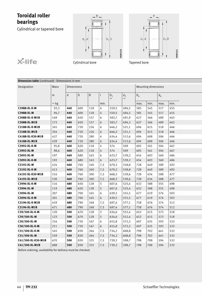
Toroidal roller bearingsCylindrical or tapered bore
Cylindrical bore Tapered bore
0008
1E29
0008
1E29
0008
1E41
0008
1E41
Before ordering, availability for delivery must be checked.
Dimension table (continued) · Dimensions in mm
Designation Mass Dimensions Mounting dimensions
m d D B r D1�
d2�
Da da
� kg min. max. min. max. min.
C3988-XL-K-M 92,3 440 600 118 4 559,5 494,5 585 545 517 455
C3988-XL-M 94,7 440 600 118 4 559,5 494,5 585 545 517 455
C3088-XL-K-M1B 169 440 650 157 6 583,7 491,9 627 566 489 463
C3088-XL-M1B 173 440 650 157 6 583,7 494,3 627 566 489 463
C3188-XL-K-M1B 345 440 720 226 6 646,2 521,1 694 615 518 466
C3188-XL-M1B 354 440 720 226 6 646,2 521,1 694 615 518 466
C4188-XL-K30-M1B 427 440 720 280 6 634,4 512,6 694 608 506 466
C4188-XL-M1B 439 440 720 280 6 634,4 512,6 694 608 506 466
C3992-XL-K-M 95,8 460 620 118 4 574 509 605 561 504 467
C3992-XL-M 98,4 460 620 118 4 574 509 605 561 504 467
C3092-XL-M 197 460 680 163 6 623,7 539,2 654 603 560 486
C3092-XL-K-M 192 460 680 163 6 623,7 539,2 654 603 560 486
C3192-XL-M 424 460 760 240 7,5 679,2 558,8 728 649 589 492
C3192-XL-K-M 413 460 760 240 7,5 679,2 558,8 728 649 589 492
C4192-XL-K30-M1B 516 460 760 300 7,5 668,3 539,6 728 634 588 477
C4192-XL-M1B 530 460 760 300 7,5 668,3 539,6 728 634 588 477
C3996-XL-K-M 116 480 650 128 5 607,6 525,4 632 588 555 498
C3996-XL-M 119 480 650 128 5 607,6 525,4 632 588 555 498
C3096-XL-M 207 480 700 165 6 639,5 555,5 677 619 576 503
C3096-XL-K-M 201 480 700 165 6 639,5 555,5 677 619 576 503
C3196-XL-K-M1B 459 480 790 248 7,5 697,4 577,1 758 676 574 512
C3196-XL-M1B 471 480 790 248 7,5 697,4 577,1 758 676 574 512
C39/500-XL-K-M 120 500 670 128 5 634,6 552,4 652 615 573 518
C39/500-XL-M 123 500 670 128 5 634,6 552,4 652 615 573 518
C30/500-XL-M 216 500 720 167 6 655,8 572,2 697 635 593 523
C30/500-XL-K-M 211 500 720 167 6 655,8 572,2 697 635 593 523
C31/500-XL-K-M 545 500 830 264 7,5 734,2 608,8 798 702 641 532
C31/500-XL-M 559 500 830 264 7,5 734,2 608,8 798 702 641 532
C41/500-XL-K30-M1B 670 500 830 325 7,5 739,2 598,7 798 708 594 532
C41/500-XL-M1B 688 500 830 325 7,5 739,2 598,7 798 708 594 532

Schaeffler Technologies TPI 232 45
Displacement distance Mounting dimensions
0009
7F36
0009
7F36
0008
1EB4
0008
1EB4
Basic load ratings Calculation factors Fatiguelimit load
Limitingspeed
Referencespeed
Ca ra s1 s2 dyn.C
stat.C0
k� k� Cu nG nB
min. max. N N N min–1 min–1
1,4 3 20 – 2 650 000 5 300 000 16,524 0,732 490 000 970 445
1,4 3 20 – 2 650 000 5 300 000 16,524 0,732 490 000 970 445
5,5 5 19,7 – 3 750 000 6 500 000 18,096 0,652 570 000 920 460
5,5 5 19,7 – 3 750 000 6 500 000 18,096 0,652 570 000 920 460
6,3 5 16 – 6 900 000 11 600 000 25,092 0,347 960 000 810 360
6,3 5 16 – 6 900 000 11 600 000 25,092 0,347 960 000 810 360
6,5 5 27,8 – 7 600 000 12 900 000 29,46 0,357 1 060 000 820 305
6,5 5 27,8 – 7 600 000 12 900 000 29,46 0,357 1 060 000 820 305
1,4 3 20 – 2 750 000 5 600 000 16,651 0,732 510 000 940 425
1,4 3 20 – 2 750 000 5 600 000 16,651 0,732 510 000 940 425
2,2 5 33,5 – 4 000 000 7 500 000 18,559 0,647 640 000 850 400
2,2 5 33,5 – 4 000 000 7 500 000 18,559 0,647 640 000 850 400
2,1 6 51 – 6 800 000 12 000 000 25,204 0,441 1 010 000 760 350
2,1 6 51 – 6 800 000 12 000 000 25,204 0,441 1 010 000 760 350
6,9 6 23,3 – 8 700 000 14 900 000 32,219 0,324 1 190 000 770 280
6,9 6 23,3 – 8 700 000 14 900 000 32,219 0,324 1 190 000 770 280
3,1 4 20,4 – 3 300 000 6 200 000 19,501 0,6 610 000 880 405
3,1 4 20,4 – 3 300 000 6 200 000 19,501 0,6 610 000 880 405
2,2 5 35,5 – 4 100 000 7 800 000 18,699 0,647 660 000 820 390
2,2 5 35,5 – 4 100 000 7 800 000 18,699 0,647 660 000 820 390
6,1 6 35,1 – 7 100 000 12 600 000 25,47 0,439 1 050 000 730 335
6,1 6 35,1 – 7 100 000 12 600 000 25,47 0,439 1 050 000 730 335
3,1 4 20,4 – 3 350 000 6 500 000 19,736 0,6 620 000 830 375
3,1 4 20,4 – 3 350 000 6 500 000 19,736 0,6 620 000 830 375
2,1 5 37,5 – 4 300 000 8 300 000 18,843 0,647 700 000 790 370
2,1 5 37,5 – 4 300 000 8 300 000 18,843 0,647 700 000 790 370
4,4 6 75,3 – 7 500 000 12 900 000 25,64 0,441 1 090 000 680 330
4,4 6 75,3 – 7 500 000 12 900 000 25,64 0,441 1 090 000 680 330
7,5 6 15 – 10 700 000 19 100 000 36,213 0,287 1 410 000 680 225
7,5 6 15 – 10 700 000 19 100 000 36,213 0,287 1 410 000 680 225

46 TPI 232 Schaeffler Technologies
Toroidal roller bearingsCylindrical or tapered bore
Cylindrical bore Tapered bore
0008
1E29
0008
1E29
0008
1E41
0008
1E41
Before ordering, availability for delivery must be checked.
Dimension table (continued) · Dimensions in mm
Designation Mass Dimensions Mounting dimensions
m d D B r D1�
d2�
Da da
� kg min. max. min. max. min.
C39/530-XL-K-M 143 530 710 136 5 658 577 692 639 606 548
C39/530-XL-M 146 530 710 136 5 658 577 692 639 606 548
C30/530-XL-M 292 530 780 185 6 702,9 602,1 757 677 628 553
C30/530-XL-K-M 285 530 780 185 6 702,9 602,1 757 677 628 553
C31/530-XL-M 625 530 870 272 7,5 779,2 636,8 838 738 678 562
C31/530-XL-K-M 609 530 870 272 7,5 779,2 636,8 838 738 678 562
C39/560-XL-K-M 164 560 750 140 5 701,7 621,3 732 683 650 578
C39/560-XL-M 168 560 750 140 5 701,7 621,3 732 683 650 578
C30/560-XL-M 338 560 820 195 6 758,9 662,1 793 735 686 583
C30/560-XL-K-M 329 560 820 195 6 758,9 662,1 793 735 686 583
C31/560-XL-K-M1B 701 560 920 280 7,5 805,2 663,4 888 778 660 592
C31/560-XL-M1B 720 560 920 280 7,5 805,2 663,4 888 778 660 592
C39/600-XL-K-M 197 600 800 150 5 745,3 664,7 782 726 685 618
C39/600-XL-M 203 600 800 150 5 745,3 664,7 782 726 685 618
C30/600-XL-M 383 600 870 200 6 805,6 691,4 847 773 724 623
C30/600-XL-K-M 373 600 870 200 6 805,6 691,4 847 773 724 623
C31/600-XL-K-M1B 847 600 980 300 7,5 869,9 702,9 948 837 699 632
C31/600-XL-M1B 869 600 980 300 7,5 869,9 702,9 948 837 699 632
C41/600-XL-K30-M1B 1 058 600 980 375 7,5 864,7 701,2 948 828 695 632
C41/600-XL-M1B 1 086 600 980 375 7,5 864,7 701,2 948 828 695 632
C39/630-XL-K-M 253 630 850 165 6 790,8 693,2 827 766 729 653
C39/630-XL-M 259 630 850 165 6 790,8 693,2 827 766 729 653
C30/630-XL-M 460 630 920 212 7,5 841,7 715,2 892 809 748 658
C30/630-XL-K-M 448 630 920 212 7,5 841,7 715,2 892 809 748 658
C31/630-XL-K-M1B 983 630 1 030 315 7,5 910,9 743,4 998 878 739 662
C31/630-XL-M1B 1 009 630 1 030 315 7,5 910,9 743,4 998 878 739 662
C39/670-XL-K-M 289 670 900 170 6 852,8 756,2 877 833 749 693
C39/670-XL-M 296 670 900 170 6 852,8 756,2 877 833 749 693
C30/670-XL-M 568 670 980 230 7,5 902,3 776,7 952 870 809 698
C30/670-XL-K-M 553 670 980 230 7,5 902,3 776,7 952 870 809 698
C31/670-XL-K-M1B 1 167 670 1 090 336 7,5 963,7 786 1 058 930 782 702
C31/670-XL-M1B 1 198 670 1 090 336 7,5 963,7 786 1 058 930 782 702

Schaeffler Technologies TPI 232 47
Displacement distance Mounting dimensions
0009
7F36
0009
7F36
0008
1EB4
0008
1EB4
Basic load ratings Calculation factors Fatiguelimit load
Limitingspeed
Referencespeed
Ca ra s1 s2 dyn.C
stat.C0
k� k� Cu nG nB
min. max. N N N min–1 min–1
2,9 4 28,4 – 3 550 000 7 100 000 19,946 0,6 670 000 790 365
2,9 4 28,4 – 3 550 000 7 100 000 19,946 0,6 670 000 790 365
2,5 5 35,7 – 5 200 000 9 700 000 21,626 0,548 790 000 730 340
2,5 5 35,7 – 5 200 000 9 700 000 21,626 0,548 790 000 730 340
3 6 44,4 – 9 100 000 16 100 000 30,734 0,356 1 310 000 640 280
3 6 44,4 – 9 100 000 16 100 000 30,734 0,356 1 310 000 640 280
2,9 4 32,4 – 3 650 000 7 500 000 20,33 0,6 700 000 730 335
2,9 4 32,4 – 3 650 000 7 500 000 20,33 0,6 700 000 730 335
2,4 5 45,7 – 5 700 000 11 200 000 22,141 0,548 890 000 660 295
2,4 5 45,7 – 5 700 000 11 200 000 22,141 0,548 890 000 660 295
7,3 6 28 – 9 600 000 17 400 000 30,983 0,355 1 350 000 610 265
7,3 6 28 – 9 600 000 17 400 000 30,983 0,355 1 350 000 610 265
1,7 4 32,4 – 4 100 000 8 800 000 21,712 0,561 790 000 680 305
1,7 4 32,4 – 4 100 000 8 800 000 21,712 0,561 790 000 680 305
2 5 35,9 – 6 300 000 12 200 000 28,196 0,403 970 000 620 275
2 5 35,9 – 6 300 000 12 200 000 28,196 0,403 970 000 620 275
8,8 6 26,1 – 11 100 000 19 100 000 30,953 0,363 1 490 000 550 247
8,8 6 26,1 – 11 100 000 19 100 000 30,953 0,363 1 490 000 550 247
9 6 24,6 – 13 600 000 24 500 000 40,44 0,26 1 780 000 560 186
9 6 24,6 – 13 600 000 24 500 000 40,44 0,26 1 780 000 560 186
3,6 5 35,5 – 5 000 000 10 100 000 22,766 0,536 890 000 630 285
3,6 5 35,5 – 5 000 000 10 100 000 22,766 0,536 890 000 630 285
3,9 6 48,1 – 6 900 000 12 900 000 29,154 0,39 1 050 000 580 270
3,9 6 48,1 – 6 900 000 12 900 000 29,154 0,39 1 050 000 580 270
8,8 6 23,8 – 12 200 000 22 000 000 34,168 0,324 1 660 000 520 222
8,8 6 23,8 – 12 200 000 22 000 000 34,168 0,324 1 660 000 520 222
2,1 5 24,9 – 5 700 000 12 300 000 24,732 0,493 1 020 000 570 237
2,1 5 24,9 – 5 700 000 12 300 000 24,732 0,493 1 020 000 570 237
3,1 6 41,1 – 8 300 000 16 500 000 27,163 0,44 1 250 000 530 226
3,1 6 41,1 – 8 300 000 16 500 000 27,163 0,44 1 250 000 530 226
12 6 41 – 12 600 000 22 300 000 34,543 0,325 1 740 000 490 220
12 6 41 – 12 600 000 22 300 000 34,543 0,325 1 740 000 490 220

48 TPI 232 Schaeffler Technologies
Toroidal roller bearingsCylindrical or tapered bore
Cylindrical bore Tapered bore
0008
1E29
0008
1E29
0008
1E41
0008
1E41
Before ordering, availability for delivery must be checked.
Dimension table (continued) · Dimensions in mm
Designation Mass Dimensions Mounting dimensions
m d D B r D1�
d2�
Da da
� kg min. max. min. max. min.
C39/710-XL-K-M 337 710 950 180 6 877,4 772,6 927 849 802 733
C39/710-XL-M 346 710 950 180 6 877,4 772,6 927 849 802 733
C30/710-XL-M 634 710 1 030 236 7,5 943,3 808,7 1 002 906 846 738
C30/710-XL-K-M 618 710 1 030 236 7,5 943,3 808,7 1 002 906 846 738
C40/710-XL-M1B 846 710 1 030 315 7,5 931,2 806,8 1 002 899 841 738
C40/710-XL-K30-M1B 824 710 1 030 315 7,5 931,2 806,8 1 002 899 841 738
C31/710-XL-K-M1B 1 327 710 1 150 345 9,5 1 005,3 843,3 1 100 976 839 750
C31/710-XL-M1B 1 362 710 1 150 345 9,5 1 005,3 843,3 1 100 976 839 750
C39/750-XL-K-M 380 750 1 000 185 6 933,5 829,5 977 906 869 773
C39/750-XL-M 391 750 1 000 185 6 933,5 829,5 977 906 869 773
C30/750-XL-K-M1B 735 750 1 090 250 7,5 991,7 856,3 1 062 965 852 778
C30/750-XL-M1B 755 750 1 090 250 7,5 991,7 856,3 1 062 965 852 778
C39/800-XL-K-M 443 800 1 060 195 6 990,6 888,4 1 037 970 879 823
C39/800-XL-M 455 800 1 060 195 6 990,6 888,4 1 037 970 879 823
C30/800-XL-K-M1B 828 800 1 150 258 7,5 1 045,4 911,5 1 122 1 020 906 828
C30/800-XL-M1B 828 800 1 150 258 7,5 1 045,4 911,5 1 122 1 020 906 828
C39/850-XL-K-M 500 850 1 120 200 6 1 056,9 936,1 1 097 1 027 981 873
C39/850-XL-M 513 850 1 120 200 6 1 056,9 936,1 1 097 1 027 981 873
C39/900-XL-K-M 564 900 1 180 206 6 1 114,6 987,4 1 157 1 087 981 923
C39/900-XL-M 579 900 1 180 206 6 1 114,6 987,4 1 157 1 087 981 923

Schaeffler Technologies TPI 232 49
Displacement distance Mounting dimensions
0009
7F36
0009
7F36
0008
1EB4
0008
1EB4
Basic load ratings Calculation factors Fatiguelimit load
Limitingspeed
Referencespeed
Ca ra s1 s2 dyn.C
stat.C0
k� k� Cu nG nB
min. max. N N N min–1 min–1
6,5 5 30,7 – 6 100 000 12 900 000 25,417 0,479 1 040 000 550 237
6,5 5 30,7 – 6 100 000 12 900 000 25,417 0,479 1 040 000 550 237
4,3 6 47,3 – 9 000 000 17 600 000 27,717 0,435 1 360 000 500 214
4,3 6 47,3 – 9 000 000 17 600 000 27,717 0,435 1 360 000 500 214
1,3 6 31,5 – 10 300 000 21 100 000 34,772 0,321 1 560 000 510 176
1,3 6 31,5 – 10 300 000 21 100 000 34,772 0,321 1 560 000 510 176
8,7 8 47,8 – 12 700 000 24 200 000 35,044 0,324 1 810 000 465 203
8,7 8 47,8 – 12 700 000 24 200 000 35,044 0,324 1 810 000 465 203
3,8 5 35,7 – 6 400 000 14 000 000 25,91 0,479 1 120 000 510 216
3,8 5 35,7 – 6 400 000 14 000 000 25,91 0,479 1 120 000 510 216
6,9 6 25 – 9 500 000 19 300 000 29,669 0,404 1 430 000 475 201
6,9 6 25 – 9 500 000 19 300 000 29,669 0,404 1 430 000 475 201
3,6 5 45,7 – 6 600 000 14 800 000 26,416 0,479 1 160 000 475 205
3,6 5 45,7 – 6 600 000 14 800 000 26,416 0,479 1 160 000 475 205
6,9 6 25 – 9 600 000 20 100 000 30,144 0,404 1 470 000 445 191
6,9 6 25 – 9 600 000 20 100 000 30,144 0,404 1 470 000 445 191
4,5 5 35,9 – 7 800 000 17 000 000 30,626 0,398 1 390 000 440 182
4,5 5 35,9 – 7 800 000 17 000 000 30,626 0,398 1 390 000 440 182
3 5 20 – 9 000 000 20 300 000 32,311 0,377 1 570 000 410 159
3 5 20 – 9 000 000 20 300 000 32,311 0,377 1 570 000 410 159

50 TPI 232 Schaeffler Technologies
Application example Paper industry
In the dry section of a paper machine, the still damp paper webis fed over steam-heated rolls for final drying. The bearings in these dryer rolls run under high ambient temperatures in housings with recirculating oil lubrication, Figure 1.
Requirements The requirements placed on the bearing arrangement are:■ constraint-free compensation in the non-locating bearing
of substantial changes in the axial length of the roll■ compensation of possible angular defects in the locating bearing
and non-locating bearing■ resistance to substantial differences in temperature■ very high operational reliability of the bearing arrangement
(Lhmn � 100 000 h).Schaeffler offers specially developed housings for this application. Further information on the housings is available on request.
Figure 1Dryer roll in a paper machine 00
0894
E400
0894
E4
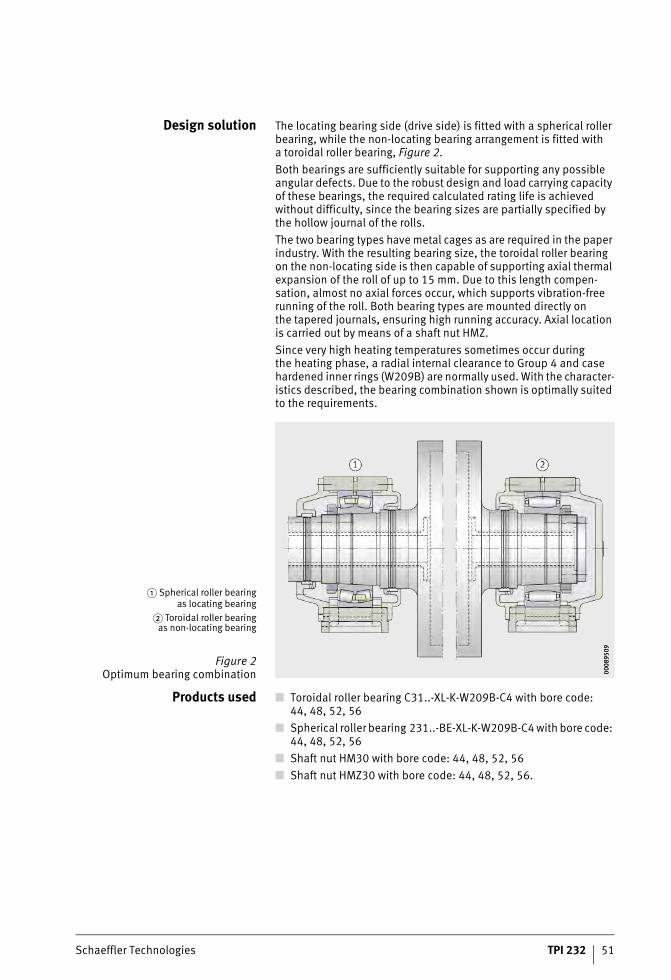
Schaeffler Technologies TPI 232 51
Design solution The locating bearing side (drive side) is fitted with a spherical roller bearing, while the non-locating bearing arrangement is fitted witha toroidal roller bearing, Figure 2.Both bearings are sufficiently suitable for supporting any possible angular defects. Due to the robust design and load carrying capacity of these bearings, the required calculated rating life is achieved without difficulty, since the bearing sizes are partially specified by the hollow journal of the rolls.The two bearing types have metal cages as are required in the paper industry. With the resulting bearing size, the toroidal roller bearing on the non-locating side is then capable of supporting axial thermal expansion of the roll of up to 15 mm. Due to this length compen-sation, almost no axial forces occur, which supports vibration-free running of the roll. Both bearing types are mounted directly onthe tapered journals, ensuring high running accuracy. Axial location is carried out by means of a shaft nut HMZ.Since very high heating temperatures sometimes occur duringthe heating phase, a radial internal clearance to Group 4 and case hardened inner rings (W209B) are normally used. With the character-istics described, the bearing combination shown is optimally suited to the requirements.
Products used ■ Toroidal roller bearing C31..-XL-K-W209B-C4 with bore code:44, 48, 52, 56
■ Spherical roller bearing 231..-BE-XL-K-W209B-C4 with bore code: 44, 48, 52, 56
■ Shaft nut HM30 with bore code: 44, 48, 52, 56■ Shaft nut HMZ30 with bore code: 44, 48, 52, 56.
� Spherical roller bearingas locating bearing
� Toroidal roller bearingas non-locating bearing
Figure 2Optimum bearing combination 00
0895
0900
0895
09
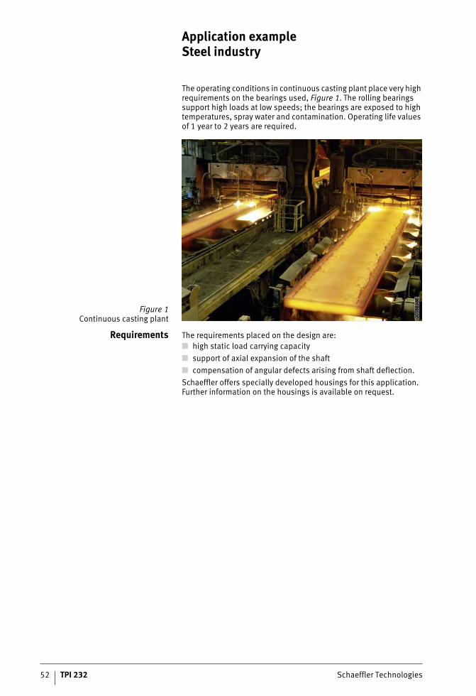
52 TPI 232 Schaeffler Technologies
Application example Steel industry
The operating conditions in continuous casting plant place very high requirements on the bearings used, Figure 1. The rolling bearings support high loads at low speeds; the bearings are exposed to high temperatures, spray water and contamination. Operating life values of 1 year to 2 years are required.
Requirements The requirements placed on the design are:■ high static load carrying capacity■ support of axial expansion of the shaft■ compensation of angular defects arising from shaft deflection.Schaeffler offers specially developed housings for this application. Further information on the housings is available on request.
Figure 1Continuous casting plant 00
08B9
8E00
08B9
8E

Schaeffler Technologies TPI 232 53
Design solution The strand guide rolls in the continuous casting plant are normally supported by means of a locating/non-locating bearing arrange-ment, Figure 2. The function of the non-locating bearings is to accommodate length expansion of the shaft as far as possible without constraint and to compensate for shaft deflection.The toroidal roller bearing can effectively compensate changesin the length of the shaft due to the facility for displacement between the inner ring and outer ring. As a result of the internal geometry, angular defects arising from shaft deflection can be compensated.Due to the full complement design in this application, the very high basic static load rating required can be achieved.
Products used ■ Toroidal roller bearing C40..-XL-V-C3 with bore code:22, 24, 26, 28, 30, 32
■ Toroidal roller bearing C40..-XL-V-C4 with bore code:22, 24, 26, 28, 30, 32
■ Toroidal roller bearing C41..-XL-V-C3 with bore code:22, 24, 26, 28, 30, 32
■ Toroidal roller bearing C41..-XL-V-C4 with bore code:22, 24, 26, 28, 30, 32.
� Strand guide rolls� Toroidal roller bearings
Figure 2Bearing arrangementof strand guide rolls 00
0870
F000
0870
F0

54 TPI 232 Schaeffler Technologies
Application example Ventilators
Ventilators are used in many branches of industry. In accordance with their function, they are described as fans or blowers, Figure 1. Depending on the direction of the air or gas flow, a distinctionis made between radial and axial ventilators. They are used,for example, to improve the interior climate and aerate production buildings, tunnels and mines. In processes, they can accelerate combustion processes, start and maintain operation of process plant by means of gas mass flows or extract exhaust gases.
Requirements The rolling bearings in such machines are subject to operating conditions such as high speeds, different loads, skewing and vibrations. The media conveyed, such as heating gas, require constraint-free adjustment of the non-locating bearing during operation.Schaeffler offers specially developed housings for this application. Further information on the housings is available on request.
Figure 1Ventilators 00
0894
F600
0894
F6

Schaeffler Technologies TPI 232 55
Design solution Through the use of the toroidal roller bearing as a non-locating bearing, the axial shaft offset resulting from the dynamically variable axial thrust can be compensated without constraint, Figure 2.Furthermore, this gives the following advantages:■ constraint-free compensation within the bearing of the shaft
length – no risk of the “stick-slip effect” in the housing bore■ reduction in vibrations and noise■ lower operating temperature relative to the complete system
even under unfavourable operating conditions■ longer grease operating life■ reduced sensitivity to unbalance due to the feasibility of a tight
outer ring fit.
Products used ■ Toroidal roller bearing C22..XL-K-C3 with bore code:12 to 24
■ Toroidal roller bearing C23..XL-K-C3 with bore code:12 to 24
■ Spherical roller bearing 222..-E1-XL-K-C4■ Spherical roller bearing 223..-E1-XL-K-C4.
� Spherical roller bearing� Toroidal roller bearing
Figure 2Blower bearing arrangement 00
0895
2F00
0895
2F

56 TPI 232 Schaeffler Technologies
Application example Marine propulsion systems
For marine propulsion systems, a conceptual distinction ismade between compact designs and conventional power trains.This results in differing requirements. Across the concepts,the non-locating bearing function can be fulfilled by toroidal roller bearings, Figure 1 and Figure 2.
Figure 1Compact drives
with a 360° rotation facility fittedto the stern of a ship
0008
70C1
0008
70C1
Figure 2Rigid drive propeller at the end
of a conventional drive train
0008
70CB
0008
70CB

Schaeffler Technologies TPI 232 57
Requirements In the case of conventional drives, it is normally misalignment resulting from shaft offset and deflection that must be supported.In compact drives, such as POD drives, the challenge is associated with temperature-induced elongations. When used in a non-locating bearing solution, the significant advantages of the axial dis-placement capability of a cylindrical roller bearing and the angular adjustability of a spherical roller bearing can be combined.Schaeffler offers specially developed housings for this application. Further information on the housings is available on request.
Design solution In conventional applications, the system solution results fromthe combination with spherical roller bearings for supporting axial loads. These are caused by the thrust of the propeller. Radial loads often occur as a result of structural shaft offsets, deflections in shaft segments in the drive train and the inherent mass, Figure 3.
� Toroidal roller bearing� Radial spherical roller bearing
� Axial spherical roller bearing
Figure 3Cross-section of drive train
000A
8677
000A
8677

58 TPI 232 Schaeffler Technologies
Application example Marine propulsion systems
In nacelle drives, the toroidal roller bearing on the propeller sideacts in combination with a thrust bearing unit, normally realisedby means of two axial spherical roller bearings, Figure 4.
Products used ■ Toroidal roller bearing C30..-XL-K with bore code:64, 84, 96 or alternatively 630 mm inner ring bore
■ Radial spherical roller bearing 239..-B-K-MB with bore code:76, 80, 88 or alternatively 630 mm inner ring bore
■ Axial spherical roller bearing 294..-E1-XL with bore code:84, 88 or alternatively 600 mm, or 630 mm inner ring bore.
Figure 4Cross-section of nacelle drive 00
0A8F
E200
0A8F
E2


Schaeffler TechnologiesAG & Co. KG
Industriestraße 1–391074 HerzogenaurachGermanyInternet www.schaeffler.de/enE-mail [email protected]
In Germany:Phone 0180 5003872Fax 0180 5003873
From other countries:Phone +49 9132 82-0Fax +49 9132 82-4950
Schaeffler TechnologiesAG & Co. KG
Georg-Schäfer-Straße 3097421 SchweinfurtGermanyInternet www.schaeffler.de/enE-mail [email protected]
In Germany:Phone 0180 5003872Fax 0180 5003873
From other countries:Phone +49 9721 91-0Fax +49 9721 91-3435
Every care has been taken to ensure the
correctness of the information contained
in this publication but no liability can
be accepted for any errors or omissions.
We reserve the right to make technical
changes.
© Schaeffler Technologies AG & Co. KG
Issued: 2018, April
This publication or parts thereof may not
be reproduced without our permission.
TPI 232 GB-DMAT
NR
0822
3954
1-00
00 /
TPI
232
/ 0
2 /
GB-
D /
201
804.
5 /
Prin
ted
in G
erm
any
by h
aßfu
rter


