
Advances in Materials 2013; 2(2) : 12-22
Published online April 2, 2013 (http://www.sciencepublishinggroup.com/j/am)
doi: 10.11648/j.am.20130202.11
Tribological studies on deep cryogenic treated aisi t42 high speed steel using response surface methodology
D. Candane1,*
, N. Alagumurthi2, K. Palaniradja
2
1Department of Mechanical Engineering, Women’s Polytechnic College, Pondicherry, India 2Department of Mechanical Engineering, Pondicherry Engineering College, Pondicherry, India
Email address: [email protected] (D. Candane)
To cite this article: D. Candane, N. Alagumurthi, K. Palaniradja. Tribological Studies on Deep Cryogenic Treated Aisi T42 High Speed Steel Using Response
Surface Methodology, Advances in Materials. Vol. 2, No. 2, 2013, pp. 12-22. doi: 10.11648/j.am.20130202.11
Abstract: High – speed steels are the most widely used tool material in small and medium scale industries, owing to their
excellent toughness and economic price over their competitors. But the wear resistance and hot hardness of high-speed steels
are poor compared to tools made out of carbides. Recent investigations, on the effect of cryogenic treatment have proved to be
an alternative option to enhance the hardness and wear resistance of high-speed tool materials. But so far only a limited
number of investigations have been made into the effect of cryogenic treatment on different grades of high-speed steels. The
present research reports the effect of deep cryogenic treatment on AISI T42 grade high – speed steel, with specific emphasis
on mode and mechanism of wear. Wear behavior has been studied using pin-on-disc tribo-meter under dry condition. Re-
sponse surface methodology was adopted in designing the experiments for two factors with five levels. Mathematical model
has been developed incorporating the effect of sliding velocity and load on the wear behavior. Sliding velocity was found to
be dominant factor than normal load. Morphology of worn surface and the wear debris was studied using SEM to identify the
mode and mechanism of wear. Mild oxidative wear was the dominant mode of wear throughout the range of variables used in
this study. Deep cryogenically treated specimens exhibited significant improvement in wear resistance than conventionally
heat treated specimens, especially at higher sliding velocities. The wear rate of conventionally heat treated specimen was
found to be 3.138 to 2.493 times higher than that of deep cryogenically treated specimens. There was an increase in hardness
value form 66.8-67.2 HRC at the end of conventional heat treatment to 69.5-70.2 HRC at the end of deep cryogenic treatment.
Keywords: Cryogenic Treatment, Wear Rate, Response Surface Methodology, Mild Oxidative Wear, Morphology
1. Introduction
The demand for cutting tool material able to withstand
high forces, high contact pressures, high temperatures and
intense chemical transactions at the interface between tool
and work piece is a dynamic phenomena and its effective
management acts as a key to economy of production and
industrial competitiveness [1]. Very often, the maximum
material removal at optimum cutting conditions is the crite-
rion practiced in metal cutting operations. As a result, the
cutting tool material is always subjected close to their ulti-
mate resistance against wear and chemical activities [2].
Though there is a wide range of high performance cutting
tool materials such as carbides, cermets, ceramics and cubic
boron nitride, which address the above demands, high-
speed steel still remains a logical choice, as a tool material
for many metal cutting operations, possibly because of its
relatively high toughness, low price and possibility of eco-
nomic manufacturing of tools with complex geometry. In
certain applications such as deep drilling high speed steel is
the only choice due to its excellent toughness.
Though high- speed steel was introduced a century ago
with time it has undergone several modifications resulting in
various grades suitable for variety of applications. The
presence of allying elements and the domain of heat treat-
ment confers the required qualities. Further, the use of sec-
ondary process such as hard abrasive coating enhances the
wear resistance of these tools.
In the past two decades, there is an increasing amount of
interest, in the use of cryogenic treatment, to enhance the
wear properties of tool materials [3]. Specifically the earlier
research works carried out on the effect of cryogenic treat-
ment on high-speed steels, unambiguously confirm trans-
formations in microstructure, improvement in hardness and
wear resistance. And these changes take place across the
entire volume of material, unlike the coating technique in

Advances in Materials 2013, 2(2) : 12-22 13
which the wear property is enhanced only at the surface.
Hence coated tools lose their wear resistance, once the
coating wears out. But the advantages of cryogenically
treated tools could be brought into full potential, after every
regrinding. Therefore cryogenic treatment could spectacu-
larly reduce consumption of tool materials.
When compared to heat treatment the cryogenic treatment
is considered to be a recent development and it is still in its
infancy, requiring rigorous experimentation and optimiza-
tion before its establishment for commercial applications.
The results of cryogenic treatment largely depend on rate of
cooling, the lowest temperature used in the cycle and the
soaking time [4, 5, 6]. Apart from this a low temperature
tempering is applied at the end of cryogenic treatment to
relieve the residual stresses and promote precipitation of fine
carbides.
Until 1960s, researchers attempted to dip metallic com-
ponents in liquid nitrogen which resulted in failure of
components by cracking due to thermal shock. Later, the
breakthrough in refrigeration cycles led to the development
of cryogenic treatment systems with a feed back control on
temperature, during cooling and warm up.
The effect of cryogenic treatment on cutting tool materials
was first validated by Barron [5] in the year 1988 .He con-
firmed significant improvement in wear resistance of cryo-
genically treated AISI M2 specimens, compared to conven-
tionally heat treated specimens, in sliding abrasion wear
tests. He also verified that wear resistance still improved for
components soaked at - 196 ̊C than at - 84 ̊C for a constant
soaking time of 24 hours. He attributed improvement in
wear resistance to both transformation of retained austenite
and precipitation of fine carbide particles well distributed in
the martensite matrix.
Presence of austenite, is inevitable in heat treated high
speed steels, at the end of conventional heat treatment [7].
Rate of cooling and the presence of alloying elements de-
press the martensite start (Ms) temperature and martensite
finish (Mf) temperature. At normal cooling rates, the mar-
tensite start (Ms) temperature is lowered by 20 ˚C.Cooling
rates followed in case of hardening cycles, is much higher
and hence the martensite start (Ms) temperature is further
lowered. For eutectoid steel with 0.78 %C, transformation of
martensite reaches its completion at approximately -50 ˚C.
The following equations show the effect of alloying ele-
ments, in lowering martensite start (Ms) temperature.
Ms = 539 – 423(C) – 30 .4(Mn) – 12.1(Cr) – 17.7(Ni)- 7.5
(Mo)... ˚C
Mf = Ms – 215.... ˚C
Austenite is the softest phase and its presence in high
speed steel cutting tools is detrimental to life of tools. Wear
begins only at these soft spots, by ploughing action of hard
particles in work piece material during metal removal [8].
Leskovsek [9] investigated the wear resistance of con-
ventionally heat treated and cryogenically treated AISI M2
HSS. Wear volume was higher for samples that were con-
ventionally heat treated than those subjected to deep cryo-
genic treatment at -196 ˚C. Also he confirmed that proper
combination of hardness and fracture toughness is very
essential apart from the cryogenic treatment in order to gain
higher wear resistance.
Martensite transformed during cryogenic treatment is
very hard and brittle and it is to be conditioned before usage.
More over during transformation of austenite to martensite
in the cryogenic treatment 4 % volumetric expansion occurs,
which results in internal stresses. Hence double tempering at
150 – 200 ˚C for a period of 1.5 – 2 hours is very essential at
the end of cryogenic treatment [9, 10].
Popandopulo and Zhukova [11] observed volumetric re-
duction of high speed steel specimen during cryogenic
treatment in the temperature range of -90 to + 20˚C. Volu-
metric reduction was attributed to partial decomposition of
martensite due to thermal instability and migration of carbon
atoms to the neighboring lattice defects.
Akhbarizadeh [12] studied the wear resistance of cryo-
genically treated D6 tool steel by conducting sliding brasion
wear test. He confirmed that shallow cryogenic treated spe-
cimens with 40 hours cycle exhibited better wear characte-
ristics than those with 20 hours cycle. He attributed the
improvement in wear resistance to reduction of austenite in
case of shallow cryogenic treated specimens with 40 hours
cycle than that with 20 hours cycle. He also observed that
cryogenically treated specimens stabilized for a period of
one week at room temperature performed better than non
stabilized specimen in the wear test.
S.Kumar [13] used statistically designed experimental
procedure to evaluate wear behavior of powder metallurgy
composites. Response surface methodology was used to
develop a mathematical model of wear behavior. Such a
model could be used to predict, off-hand the effects of dif-
ferent factors on wear behavior.
In the present work, samples of AISI T42 HSS have been
subjected to conventional heat treatment at hardening tem-
perature of 1230 ̊ C. Subsequently the samples were sub-
jected to deep cryogenic treatment at -195 ̊ C with a soaking
time of 24 hours.
Sliding abrasion wear test was conducted on both con-
ventionally heat treated specimens and deep cryogenic
treated specimens to compare their wear behavior and to
identify the mode and mechanism of wear. Discs made of
En24 steel were used as counter face material to study the
wear behavior of pin at different loads and sliding speeds.
2. Materials and Experimental Proce-
dure
2.1. Material
High - speed steels are broadly classified as molybdenum
based and tungsten based high- speed steels. AISI T42 is
tungsten based high-speed steel with maximum of 10 %
cobalt content. It is a special grade suitable for gear cutters,
form tools and milling cutters. Any improvement in hard-

14 D. Candane et al.: Tribological studies on deep cryogenic treated aisi t42 high speed steel using
response surface methodology
ness and wear behavior due to cryogenic treatment, could
add value to metal cutting operations and hence the speci-
mens were prepared out of AISI T42 grade high-speed steel
having the following nominal composition.
Table 1. Chemical composition of AISI T42.
Elements % Weight Elements % Weight
C 1.5 Ni 0.422
Si 0.291 Co 9.75
Mn 0.232 Cu 0.147
P 0.023 Nb 0.012
S 0.005 Ti 0.007
Cr 4.21 V >2.0
Mo 3.19 W 8.95
2.2. Conventional Heat Treatment
Conventional heat treatment was carried out in a barium
chloride salt bath furnace as per the following sequence.
Preheating was done at 450˚C in FAC furnace for half an
hour. Next stage of preheating was carried out in barium
chloride salt bath furnace maintained at 950˚C for a period
of 6 minutes. Finally the specimens were transferred to
hardening furnace maintained at 1230˚C and soaked for a
period of 40 seconds for austenitization to take place. Later
the specimens were suddenly quenched in salt bath furnace
maintained at 560˚C and soaked for a period of 20 minutes
for stabilization of phases. Subsequently the specimens were
air cooled up to room temperature.
The as quenched hardness was checked and it was found
to be 64.2 to 65 HRC. To condition the martensite and to
promote further transformation of carbides the specimens
were triple tempered in salt bath furnace maintained at
540˚C with a soaking time of 90 minutes for each tempering
cycle. Final hardness reached was found to be 66.8 to 67.2
HRC.
2.3. Deep Cryogenic Treatment
Since it is a comparative study on the effect of deep
cryogenic treatment, on wear behavior, all the specimens at
the end of conventional heat treatment were divided into two
sets. Out of the two only one set was considered for deep
cryogenic treatment.
And these specimens were loaded in the cryogenic
treatment chamber and they were slowly cooled at a constant
rate of -0.5˚C per minute until they reach -195˚C .Specimens
were soaked at -195˚C for a period of 24 hours to allow for
complete transformation reactions. Later, the specimens
were warmed up at the rate of 0.5˚C per minute up to room
temperature. To condition the martensite formed during
deep cryogenic treatment and to promote precipitation of
fine carbides the specimens were double tempered at 200˚C
with a stabilization time of 2 hours for each cycle. The final
hardness value at the end of deep cryogenic treatment and
double tempering was found to be 69.5 to 70.2 HRC.
Fig. 1. Conventional Heat Treatment Cycle for AISI T42.
2.4. Preparation of Specimens
Ducom pin on disc wear tester with stationary pin and
rotating disc configuration was used for conducting sliding
abrasion wear study. The wear tests were conducted at a
constant room temperature of 25˚C and relative humidity
60%, under dry condition. Cylindrical pins of diameter 10
mm with h7 tolerance and length 20mm were prepared from
AISI T42 bar of 12 mm square cross section. Ends of the pin
were polished using progressively finer grades of sand paper
up to 1200 mesh. The weight of the specimens was recorded
using a scale with precession of 10-5
gm, before loading
them on wear tester. Discs of Ø55mm and thickness 10 mm
with four holes of Ø3.5mm on pitch circle of Ø47 mm were
made out of En 24 steel with C - 0.41%, Mn - 0.57%, Si - 0.24%, S - 0.01%, P - 0.03%, Cr - 1.21%, Ni – 1.47%, Mo – 0.28%. Surface of disc was polished to the same finish as
that of pins, before conducting the wear study.
Fig. 2. Deep Cryogenic Treatment Cycle for AISI T42.
2.5. Design of Experiment
In order to investigate the wear behavior over a wide
range of sliding velocity and normal load, response surface
methodology was adopted. It is a statistical experimental
design procedure that is very ideal, especially when the
levels factors are more than two. Since, five levels of sliding
speed and load were chosen for the experimental study a full,
central composite design, with alpha value of 1.414 was
used in designing the experiment. The centre point was
replicated five times to account for experimental errors.
Initial screening tests were done to assess the probable
range of the factors and constants. Since the disc used in the
wear study was made out of plain En 24 with hardness of 14
HRC there was an appreciable amount of wear in pin ma-
terial only for sliding distance above 1500 m-2000m. In
order to make sure that the wear behavior of pin corresponds
to steady state regime, the sliding distance was chosen to be
3000m for all the tests.

Advances in Materials 2013, 2(2) : 12-22 15
The lower and upper limits of sliding velocity was chosen
between 0.4m/sec and 1.0 m/sec with a view to correlate the
wear behavior of pin with the wear behavior of single point
cutting tool. The lowest and highest limits of sliding velocity
were decided based on the alpha value adopted in this ex-
perimental design.
Similarly the limits of normal load were decided based on
earlier research carried out in similar wear studies. Wear
tests were conducted as per the randomized order given in
the design Table 4. For every run, the experiment was re-
peated twice and the weight loss of pin was recorded. The
average value of weight loss was entered in the response
column. The data obtained after conducting all wear tests
was analyzed using analysis of variance (ANOVA) tech-
nique. According to this technique, the calculated value of
Fratio using the developed model, should not exceed the
standard tabulated value of Fratio, for a desired level of con-
fidence (95 %), for the model to be adequate.
Table 2. Factors and their levels for sliding wear test.
Factors Levels
-1.414 -1 0 +1 +1.414
Sliding
Velocity
‘V’ m/sec
0.28 0.4 0.7 1.0 1.2
Normal
Load
‘P’
N
64.64 75 100 125 135.36
Table 4. ANOVA for Weight Loss of Conventionally Heat Treated AISIT42
specimens.
Source SS df MS F P-Value
Model 1.468E-004 5 2.937E-005 56.55 <0.0001
A-Sliding
Velocity 1.025E-004 1 1.025E-004 197.39 <0.0001
B-Load 1.983E-005 1 1.983E-005 38.19 0.0005
AB 1.560E-007 1 1.560E-007 0.30 0.6006
A2 2.354E-005 1 2.354E-005 45.33 0.0003
B2 2.316E-006 1 2.316E-006 4.46 0.0726
Residual 3.635E-006 7 5.193E-007
Lack of fit 1.323E-007 3 4.409E-008 0.05 0.9830
Pure
Error 3.503E-006 4 8.757E-007
Cor Total 1.505E-004 12
3. Results of Wear Test
Since it is a comparative study on the wear behavior of
conventionally heat treated and deep cryogenic treated spe-
cimens the wear tests were carried out under identical con-
ditions for both the cases. Design Expert v.7 was used in
developing the experimental design and analysis of the data.
The randomized order in which wear tests were conducted is
given in table -3, along with weight loss of pin in the re-
sponse column. The weight loss data obtained from wear test
has been analyzed using ANOVA technique, for testing the
adequacy of the developed model. Significance of the model
terms and lack of fit were analyzed.
Table 3. Experimental Design Table for pin –on –disc war test of Conven-
tionally Heat Treated AISIT42 specimens.
Run
order
Factor: 1
Sliding
Velocity‘V’
‘m/sec’
Factor: 2
Normal
Load‘P’
‘N’
Response
Weight
Loss
‘gm’
1 0.7 100 0.00595
2 0.4 75 0.00266
3 1.12 100 0.01415
4 0.28 100 0.00419
5 1.0 125 0.01286
6 0.7 100 0.00448
7 0.7 100 0.00489
8 0.7 64.64 0.00426
9 0.7 100 0.00539
10 0.4 125 0.00598
11 0.7 135.36 0.00903
12 0.7 100 0.00687
13 1.0 75 0.01033
Table 4 is the ANOVA output obtained using Design
Expert software.
Fratio calculated using the developed model is 0.05, which
is less than tabulated value, F0.05, 3, 4 = 6.59. Therefore, lack
of fit is not significant and the model is adequate. Hence the
wear model can be used to navigate through space.
Wear Model in terms of actual factors:
Weight Loss = 8.26978x10⁻³ - 0.01405V -1.03228x10⁻⁴P
- 2.63333x10⁻⁵VP + 0.020439V2 + 9.232x10⁻⁷P2
Fig. 3. Response surface graph in 2D for weight Loss of Conventionally
Heat Treated AISIT42 specimens.

16 D. Candane et al.: Tribological studies on deep cryogenic treated aisi t42 high speed steel using
response surface methodology
Fig. 4. Response surface graph in 3D for weight Loss of Conventionally
Heat Treated AISIT42 specimens.
Table 5. Experimental Design Table for pin –on –disc war test of Deep
Cryogenically Treated AISIT42 specimens.
Run
order
Factor: 1
Sliding
Velocity‘V’
‘m/sec’
Factor: 2
Normal
Load‘P’
‘N’
Response
Weight
Loss
‘gm’
1 0.7 100 0.00358
2 0.28 100 0.00298
3 1.0 75 0.00406
4 0.7 100 0.0034
5 0.7 64.64 0.00287
6 0.7 135.36 0.00578
7 0.7 100 0.00309
8 1.0 125 0.00634
9 1.2 100 0.00532
10 0.7 100 0.00376
11 0.4 125 0.0043
12 0.4 75 0.00226
13 0.7 100 0.00421
Table 6. ANOVA for Weight Loss of Deep Cryogenically Treated AISI T42
specimens.
Source SS df MS F P-Value
Model 1.655E-005 5 3.311E-006 31.39 0.0001
A-Sliding
Velocity 6.389E-006 1 6.389E-006 60.57 0.0001
B-Load 8.894E-006 1 8.894E-006 84.33 <0.0001
AB 1.440E-008 1 1.440E-008 0.14 0.7227
A2 5.133E-007 1 5.133E-007 4.87 0.0632
B2 8.972E-007 1 8.972E-007 8.51 0.0225
Residual 7.383E-007 7 1.005E-007
Lack of fit 4.046E-008 3 1.349E-008 0.077 0.9690
Pure
Error 6.979E-007 4 1.745E-007
Cor Total 1.729E-005 12
Fratio calculated using the developed model is 0.077, which
is less than tabulated value F0.05, 3, 4 = 6.59. Therefore, lack of
fit is not significant and the model is adequate. Hence the
wear model can be used to navigate through space
Wear Model in terms of actual factors:
Weight Loss = 5.08997x10⁻³ -2.04642x10⁻³ V
-7.83432x10⁻⁵P +8x10⁻⁶VP +3.01806x10⁻³ V2 +
5.746x10⁻⁷P2
Fig. 5. Response surface graph in 2D for weight Loss of Cryogenically
Treated AISIT42 specimens.
Fig. 6. Response surface graph in 3D for weight Loss of Cryogenically
Treated AISIT42 specimens.
Based on the predictive model for weight loss, the wear

Advances in Materials 2013, 2(2) : 12-22 17
rates wear calculated within the range of sliding velocity and
load used in this study. Fig-7 shows the effect of sliding
velocity on weight loss of pin at different loads. For a normal
load of 125N at sliding velocity 0.4m/sec weight loss of
CHT specimen is 1.42 times that of DCT specimen. At
sliding velocity of 1.2 m/sec and normal load of 125N the
weight loss of CHT specimen is found to be 2.49 times that
of DCT specimen. The trend of wear of CHT specimen
suggests that wear increases rapidly as sliding velocity in-
creases. On the other hand the trend of DCT specimen shows
a moderate increase in wear with respect to sliding velocity.
Fig. 7. Comparison of weight loss of AISI T42 pins subjected to Conven-
tional Heat Treatment (CHT) and Deep Cryogenic Treatment (DCT) under
sliding abrasive wear test.
Making reference to figure-8, where the effect of normal
load on wear behavior obtained from the model is presented.
The main inference made is that normal load is compara-
tively a less sensitive factor than sliding velocity as far as
wear is concerned. At normal load of 75N and sliding ve-
locity of 1.0m/sec weight loss of CHT specimen is 2.51
times that of DCT specimen. At a higher load of 125 N and
sliding velocity 1.0 m/sec the weight loss of CHT specimen
is 2.06 times that of DCT specimen.
Fig. 8. Comparison of weight loss of AISI T42 pins subjected to Conven-
tional Heat Treatment (CHT) and Deep Cryogenic Treatment (DCT) under
sliding abrasive wear test.
4. Wear Rate
The wear rate was calculated in terms of wear volume
(mm3) per unit force (N) and unit distance (m).Since the
break in period, is found to be less than 7%of the total dis-
tance of 3000 m. Hence the accelerated wear during break in
period is considered negligible.
Fig. 9. Comparison of weight loss of AISI T42 pins subjected to Conven-
tional Heat Treatment (CHT) and Deep Cryogenic Treatment (DCT) under
sliding abrasive wear test.
The wear rate was calculated based on the weight loss,
over the entire sliding distance of 3000m, neglecting the
effect of unsteady state wear during the break in period [14].
Wear rate was calculated using the expression
Wr = ∆�
��� x 1000
In this expression Wr is the wear rate expressed in
‘mm3/Nm’; ∆m - weight loss of pin in g; ρ = 8.23, density
of AISI T42 HSS in ‘g/cm3’;L=3000, sliding distance in ‘m’
and F- normal load in ‘N’.
5. Morphology of Worn Surface and
Wear Debris
5.1. SEM Analysis of Wear Debris
SEM images of wear debris, corresponding to steady state
wear regime, were taken at 2500X magnification to analyze
the mode and mechanism of wear. Fig. 10 is a representative
sample of image of wear debris corresponding to CHT spe-
cimen. The image assists to infer that the disc material un-
derwent plastic deformation under the cyclic shear stress and
got peeled off from the substrate by delamination mechan-
ism. There is enough evidence of severe plastic deformation
of disc material.
18 D. Candane et al.: Tribological studies on deep cryogenic treated aisi t42 high speed steel using
response surface methodology
A B
C D
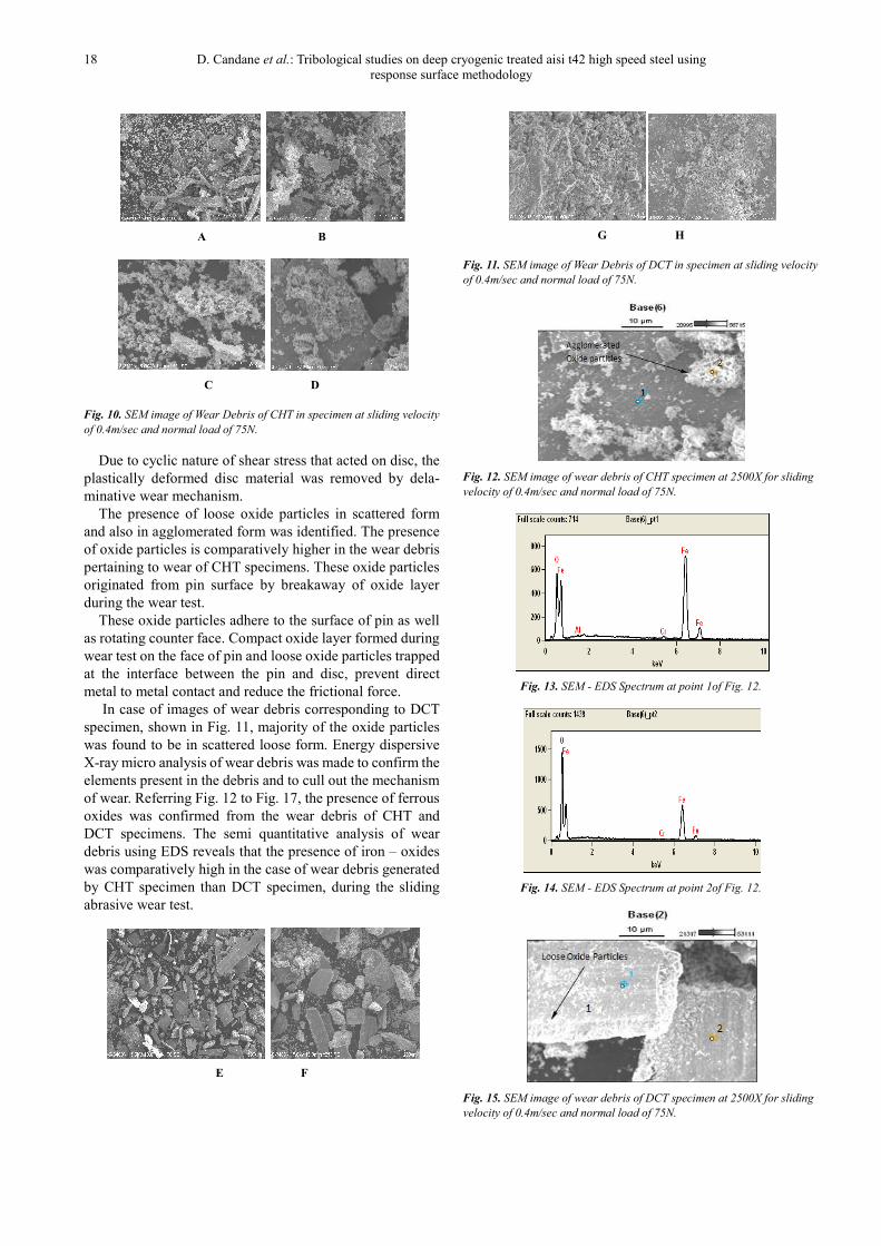
Fig. 10. SEM image of Wear Debris of CHT in specimen at sliding velocity
of 0.4m/sec and normal load of 75N.
Due to cyclic nature of shear stress that acted on disc, the
plastically deformed disc material was removed by dela-
minative wear mechanism.
The presence of loose oxide particles in scattered form
and also in agglomerated form was identified. The presence
of oxide particles is comparatively higher in the wear debris
pertaining to wear of CHT specimens. These oxide particles
originated from pin surface by breakaway of oxide layer
during the wear test.
These oxide particles adhere to the surface of pin as well
as rotating counter face. Compact oxide layer formed during
wear test on the face of pin and loose oxide particles trapped
at the interface between the pin and disc, prevent direct
metal to metal contact and reduce the frictional force.
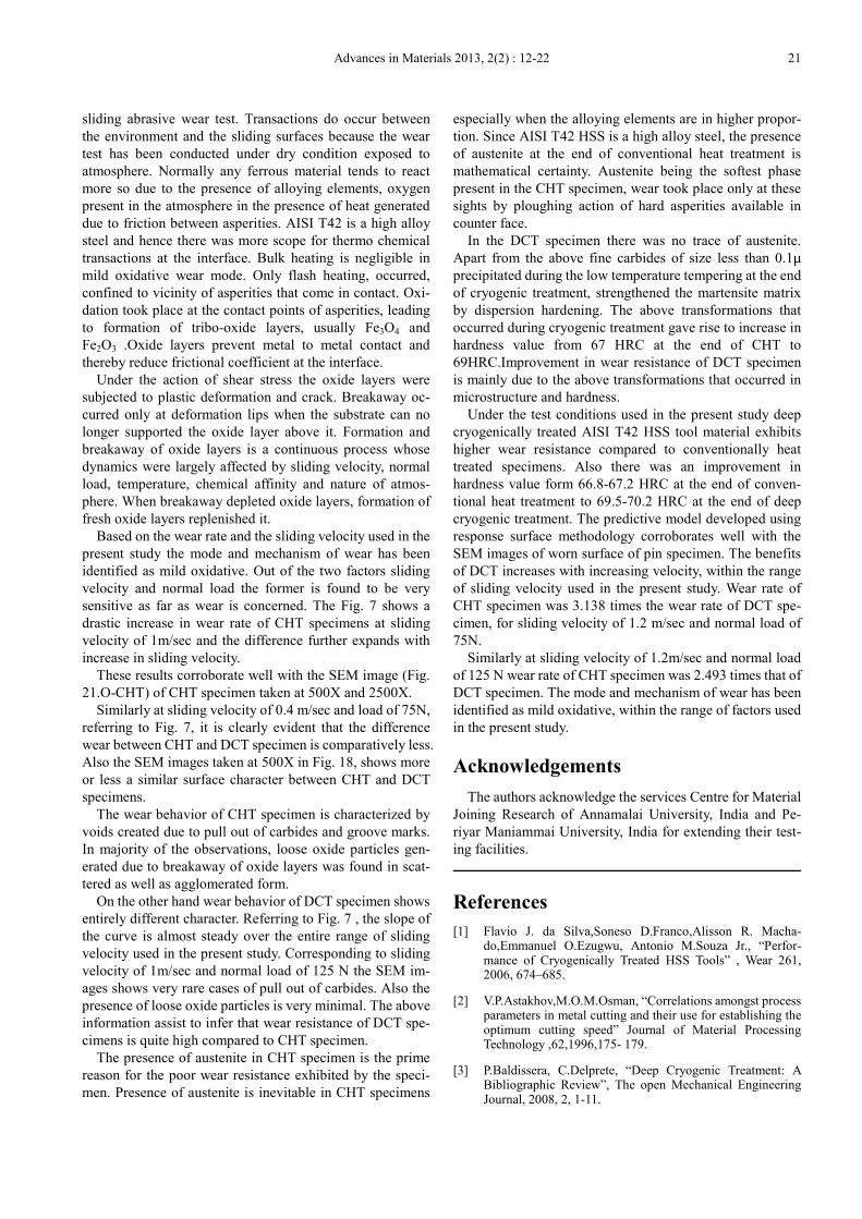
In case of images of wear debris corresponding to DCT
specimen, shown in Fig. 11, majority of the oxide particles
was found to be in scattered loose form. Energy dispersive
X-ray micro analysis of wear debris was made to confirm the
elements present in the debris and to cull out the mechanism
of wear. Referring Fig. 12 to Fig. 17, the presence of ferrous
oxides was confirmed from the wear debris of CHT and
DCT specimens. The semi quantitative analysis of wear
debris using EDS reveals that the presence of iron – oxides
was comparatively high in the case of wear debris generated
by CHT specimen than DCT specimen, during the sliding
abrasive wear test.
E F
G H
Fig. 11. SEM image of Wear Debris of DCT in specimen at sliding velocity
of 0.4m/sec and normal load of 75N.
Fig. 12. SEM image of wear debris of CHT specimen at 2500X for sliding
velocity of 0.4m/sec and normal load of 75N.
Fig. 13. SEM - EDS Spectrum at point 1of Fig. 12.
Fig. 14. SEM - EDS Spectrum at point 2of Fig. 12.
Fig. 15. SEM image of wear debris of DCT specimen at 2500X for sliding
velocity of 0.4m/sec and normal load of 75N.

Advances in Materials 2013, 2(2) : 12-22 19
Fig. 16. SEM - EDS Spectrum at point 1of Fig. 15.
Fig. 17 .SEM - EDS Spectrum at point 2of Fig. 15.
5.2. Mode and Mechanism of Wear
The topography of worn surface was analyzed using
scanning electron microscope to study the extent of surface
damage and to identify the mode and mechanism of wear.
Representative samples of SEM images of worn pin surface
taken at 500X and 2500X magnification are presented here.
The images at the left hand side correspond to CHT speci-
men and those at the right hand side correspond to DCT so as
to compare and contrast the effect of cryogenic treatment on
the wear behavior.
The maximum wear rate observed in the present study
corresponds to that of CHT specimen and its value is found
to be less than 9x10⁻⁹
mm3/N.mm. Wang et al [15] in an
earlier research suggested that for steel specimens, the upper
limit of wear rate for mild oxidative wear is 1x10 -8
mm3/N.mm. And the lower limit of wear rate for severe
delaminative wear is 2x10 -8
mm3/N.mm. Also the author
indicated that the term transition wear could be used if wear
rate lies between 1-2 x10 -8
mm3/N.mm.
Also Lim et al [16] reported that for steel specimens mild
oxidative wear occurs at sliding velocity just above 1m/sec
and moderate values of normal load. Mild oxidative wear
occurs event at sliding velocity of 0.5 m/sec for higher val-
ues of normal load. The wear mode shifts to severe oxidative
wear at sliding velocity of 10m/sec and above.
The maximum value of sliding velocity encountered in
the present study is 1.2m/sec and also the maximum amount
of wear rate encountered in the present study is well below
the upper limit of wear rate for mild oxidative wear. The
above information assists to infer that the wear mechanism
encountered in the present study corresponds to mild oxid-
ative wear.
As the present wear study has been carried out in dry
sliding abrasion configuration open to atmosphere, transac-
tions occurred at the interface between pin and disc. The
bulk heating effect was negligible in the mild oxidative
regime and only flash heating occurred at asperities that
come in contact at the interface. The increase in temperature
in this case was confined to only asperities. Once the tem-
perature at the asperities reached a value high enough to
cause oxidation, formation of oxide layers took place.
Referring to Fig. 18, at sliding velocity of 0.4m/sec and
normal load of 75 N, a lot of contrast in wear behavior could
be noticed. Compact oxide layers are found in both CHT and
DCT specimens. Intergranular wear grooves are identified
and a number of voids created by pull out of primary car-
bides (PCs) are observed in oxide depleted areas of CHT
specimen (C-CHT). Whereas the surface of DCT specimen
presents a very smooth texture at magnification of 2500X
(D-DCT).
A-CHT B-DCT
C-CHT D-DCT
Fig. 18. SEM image of worn surfaces of pins subjected to Conventional
Heat Treatment(A&C) and Deep Cryogenic Treatment (B&D) for Sliding
Velocity = 0.4 m/sec & Normal Load = 75N.
Making reference to Fig. 19, for sliding velocity of
0.4m/sec and normal load of 125N, there is noticeable
amount of plastic deformation of oxide layers stretched in
the direction of sliding (G-CHT). Deformation has been
caused by increase in normal load. The breakaway of oxide
layers has occurred and fine fragments of loose oxide par-
ticles are noticeable in CHT specimen. Formation of new
oxide layers consequent to the breakaway of older oxide
layer is observed in CHT specimen (G-CHT). In case of
CHT specimen number of voids (G-CHT) due to pull out of
carbides is visible but the number of such voids (H-DCT) are
comparatively lesser in the DCT specimen than CHT spe-
cimen.

20 D. Candane et al.: Tribological studies on deep cryogenic treated aisi t42 high speed steel using
response surface methodology
E-CHT F-DCT
G-CHT H-DCT
Fig. 19. SEM image of worn surfaces of pins subjected to Conventional
Heat Treatment(E&G) and Deep Cryogenic Treatment (F&H) for Sliding
Velocity = 0.4 m/sec & Normal Load = 125N.
Referring to Fig. 20, for a sliding velocity of 1.0 m/sec
and normal load of 75N, presence of fine particles of broken
oxide layers across the entire field, is clearly noticed
(I-CHT). At a magnification of 2500X, the extent of surface
deterioration is found to be higher (K-CHT). Population of
loose oxide particles due to the breakaway of oxide layer is
also higher. For the same combination of sliding velocity
and normal load, DCT specimen exhibits excellent surface
integrity (L-DCT) and extent of surface damage is far less
compared to CHT specimen.
I-CHT J-DCT
K-CHT L-DCT
Fig. 20. SEM image of worn surfaces of pins subjected to Conventional
Heat Treatment(I&K) and Deep Cryogenic Treatment (J&L) for Sliding
Velocity = 1.0 m/sec & Normal Load = 75N.
Referring to Fig. 21, at sliding velocity of 1.0 m/sec and
normal load of 125N the SEM image (M-CHT) taken at
500X magnification shows a extremely different wear be-
havior between CHT and DCT specimens.
M-CHT N-DCT
O-CHT P-DCT
Fig. 21. SEM image of worn surfaces of pins subjected to Conventional
Heat Treatment(M&O) and Deep Cryogenic Treatment (N&P) for Sliding
Velocity = 1.0 m/sec & Normal Load = 125N.
Extent of deformation of compact oxide layer is higher
and completely different from the previous case. Deforma-
tion lips and sub surface cracks are clearly visible even at
500X magnification. Deformation lips stretched in the
sliding direction clearly indicates that sever plastic defor-
mation has occurred in this case. This is mainly due to the
increase in normal load coupled with increase in sliding
velocity.
Whereas the image of DCT specimen at 500X (N-DCT)
indicates only mild patches of compact oxide layers whose
size is far lesser than that of CHT specimen. Image (O-CHT)
at 2500X shows presence of many voids due to pull out of
carbides, presence of loose oxide particles in scattered and
agglomerated form in CHT specimen. But in the DCT spe-
cimen voids due to pull out of primary carbides (PCs) are
comparatively less (P-DCT). Deformation of compact oxide
layers in the direction of sliding and breakaway of oxide
particles from the deformation lips is clearly observed.
Population of such loose oxide particles is also compara-
tively less (P-DCT) in DCT specimen.
6. Discussions
There will be some form of transactions, at the interface
between the disc and the surface of the pin in contact, during
Advances in Materials 2013, 2(2) : 12-22 21
sliding abrasive wear test. Transactions do occur between
the environment and the sliding surfaces because the wear
test has been conducted under dry condition exposed to
atmosphere. Normally any ferrous material tends to react
more so due to the presence of alloying elements, oxygen
present in the atmosphere in the presence of heat generated
due to friction between asperities. AISI T42 is a high alloy
steel and hence there was more scope for thermo chemical
transactions at the interface. Bulk heating is negligible in
mild oxidative wear mode. Only flash heating, occurred,
confined to vicinity of asperities that come in contact. Oxi-
dation took place at the contact points of asperities, leading
to formation of tribo-oxide layers, usually Fe3O4 and
Fe2O3 .Oxide layers prevent metal to metal contact and
thereby reduce frictional coefficient at the interface.
Under the action of shear stress the oxide layers were
subjected to plastic deformation and crack. Breakaway oc-
curred only at deformation lips when the substrate can no
longer supported the oxide layer above it. Formation and
breakaway of oxide layers is a continuous process whose
dynamics were largely affected by sliding velocity, normal
load, temperature, chemical affinity and nature of atmos-
phere. When breakaway depleted oxide layers, formation of
fresh oxide layers replenished it.
Based on the wear rate and the sliding velocity used in the
present study the mode and mechanism of wear has been
identified as mild oxidative. Out of the two factors sliding
velocity and normal load the former is found to be very
sensitive as far as wear is concerned. The Fig. 7 shows a
drastic increase in wear rate of CHT specimens at sliding
velocity of 1m/sec and the difference further expands with
increase in sliding velocity.
These results corroborate well with the SEM image (Fig.
21.O-CHT) of CHT specimen taken at 500X and 2500X.
Similarly at sliding velocity of 0.4 m/sec and load of 75N,
referring to Fig. 7, it is clearly evident that the difference
wear between CHT and DCT specimen is comparatively less.
Also the SEM images taken at 500X in Fig. 18, shows more
or less a similar surface character between CHT and DCT
specimens.
The wear behavior of CHT specimen is characterized by
voids created due to pull out of carbides and groove marks.
In majority of the observations, loose oxide particles gen-
erated due to breakaway of oxide layers was found in scat-
tered as well as agglomerated form.
On the other hand wear behavior of DCT specimen shows
entirely different character. Referring to Fig. 7 , the slope of
the curve is almost steady over the entire range of sliding
velocity used in the present study. Corresponding to sliding
velocity of 1m/sec and normal load of 125 N the SEM im-
ages shows very rare cases of pull out of carbides. Also the
presence of loose oxide particles is very minimal. The above
information assist to infer that wear resistance of DCT spe-
cimens is quite high compared to CHT specimen.
The presence of austenite in CHT specimen is the prime
reason for the poor wear resistance exhibited by the speci-
men. Presence of austenite is inevitable in CHT specimens
especially when the alloying elements are in higher propor-
tion. Since AISI T42 HSS is a high alloy steel, the presence
of austenite at the end of conventional heat treatment is
mathematical certainty. Austenite being the softest phase
present in the CHT specimen, wear took place only at these
sights by ploughing action of hard asperities available in
counter face.
In the DCT specimen there was no trace of austenite.
Apart from the above fine carbides of size less than 0.1µ
precipitated during the low temperature tempering at the end
of cryogenic treatment, strengthened the martensite matrix
by dispersion hardening. The above transformations that
occurred during cryogenic treatment gave rise to increase in
hardness value from 67 HRC at the end of CHT to
69HRC.Improvement in wear resistance of DCT specimen
is mainly due to the above transformations that occurred in
microstructure and hardness.
Under the test conditions used in the present study deep
cryogenically treated AISI T42 HSS tool material exhibits
higher wear resistance compared to conventionally heat
treated specimens. Also there was an improvement in
hardness value form 66.8-67.2 HRC at the end of conven-
tional heat treatment to 69.5-70.2 HRC at the end of deep
cryogenic treatment. The predictive model developed using
response surface methodology corroborates well with the
SEM images of worn surface of pin specimen. The benefits
of DCT increases with increasing velocity, within the range
of sliding velocity used in the present study. Wear rate of
CHT specimen was 3.138 times the wear rate of DCT spe-
cimen, for sliding velocity of 1.2 m/sec and normal load of
75N.
Similarly at sliding velocity of 1.2m/sec and normal load
of 125 N wear rate of CHT specimen was 2.493 times that of
DCT specimen. The mode and mechanism of wear has been
identified as mild oxidative, within the range of factors used
in the present study.
Acknowledgements
The authors acknowledge the services Centre for Material
Joining Research of Annamalai University, India and Pe-
riyar Maniammai University, India for extending their test-
ing facilities.
References
[1] Flavio J. da Silva,Soneso D.Franco,Alisson R. Macha-do,Emmanuel O.Ezugwu, Antonio M.Souza Jr., “Perfor-mance of Cryogenically Treated HSS Tools” , Wear 261, 2006, 674–685.
[2] V.P.Astakhov,M.O.M.Osman, “Correlations amongst process parameters in metal cutting and their use for establishing the optimum cutting speed” Journal of Material Processing Technology ,62,1996,175- 179.
[3] P.Baldissera, C.Delprete, “Deep Cryogenic Treatment: A Bibliographic Review”, The open Mechanical Engineering Journal, 2008, 2, 1-11.

22 D. Candane et al.: Tribological studies on deep cryogenic treated aisi t42 high speed steel using
response surface methodology
[4] D.Das, K.K.Ray, A.K.Dutta, “Influence of Temperature of Sub-Zero Treatments on the Wear Behaviour of Die Steel”, Wear 267, 20 09, 13 61–1370.
[5] Barron, R.F. “Cryogenic treatment of metals to improve wear resistance”, Cryogenics 22, 1982, 409–414.
[6] A.Akhbarizadeh, A.Shafyei, M.A.Golozar, “Effects of cryogenic treatment on wear behavior of D6 tool steel”, Materials and Design 30 ,2009, 3259–3264.
[7] S.Harish, A.Bensely, D.Mohan Lal, A.Rajadurai,GyongyverB.Lenkey “Microstructural Study of Cryogenically Treated En 31 Bearing Steel”, Journal of Ma-terials Processing Technology 2 0 9, 2009, 3351–3357.
[8] Sture Hogmark,Mikael Olsson, “Wear Mechanism of HSS Cutting Tools”.
[9] V.Leskovesk, M.Kalin, J.Vizintin, “Influence of Deep-Cryogenic Treatment on Wear Resistance of Vacuum Heat-Treated HSS”, Vacuum 80, 2006, 507 – 518.
[10] D.Das, A.K.Dutta, K.K.Ray “Correlation of Microstructure with Wear Behaviour of Deep Cryogenically Treated AISI D2 Steel”, Wear 267, 2009, 1371–1380.
[11] A.N.Popandopulo,L.T.Zhukova, “Transformations in High Speed Steels During Cold Treatment (Translated from Me-tallovedenie I Termicheskaya Obrabotka Metal-lor),no.10,1980,pp.9-11.
[12] A.akhbarizadeh,A.Shafyei,M.A.Golozar, “effects of cryo-genic treatment on wear behavior of D6 tool steel” Materials and Design 30,2009,3259-3264.
[13] S.Kumar,V.Balasubramanian, “Developing a mathematical model to evaluate wear rate of AA7075/SiCp powder me-tallurgy composites”,Wear 264,2008,1026-1034.
[14] Amro M. Al-Qutub, Effect of heat treatment on friction and wear behavior of Al-6061 composite reinforced with 10% submicron Al2O3 particles”, The Arabian Journal for Science and Engineering, Vol.34,2009, Number 1B.
[15] Y.Wang,T.lei,J.Liu, “Tribo-metallographic behavior of high carbon steels in dry sliding;1.Wear mechanism and their transition”,Wear 231,1999,1-11.
[16] S.C.Lim, “Recent developments in wear nechanism maps”,Tribology International Vol.31,Nos.1-3,1998, pp.87-97.
B


