Download - Tuf Yak manual - TufFlight

Page 1
The Toughest R/C Planes Ever!
5376 Amalfi Drive, Clay, NY 13041 www.tufflight.com
Items Included in kit:Foam:
CNC sliced EPP “block”CNC sliced fuselage core pieces
Wood:(3) 1/32" x 2-1/4" x 24" ply(12) 1/16” x 3” x 24” balsa sheet(4) 5/16” sq x 24” balsa sticks(2) 1/2”x 18” balsa tri stock(3) 1/4” x 5/8” x 18” balsa(1) 5/8” x 3/4” x 18” balsa(1) 5/16” x 3” x 8-7/8” balsa(1) 1/4” 5/8” x 4” bass(2) 1/32” x 6” x 8” ply(2) 5/16” x 6” dowels(1) 5/16” x 2-1/2” dowel(1) 1/2” x 5/8” x 22” pine
Plastic:(4) G10 joiner pieces
(4) 1/16” clear plastic control horns(1) 3/16”" x 4" x 7" white engine plate(1) 1/16” x 2-1/4” x 15” spacer(2) 2.5 degree wedges
Hardware:(8) 10-24 x 1.5" nylon bolts(8) 10-24 nuts(8) 6-32 x 3/8” nylon bolts(2) 1/4” washers(1) 1/4-20 x 2” nylon bolt(4) 6-32 nuts(2) 6-32 x 1-1/4" bolts(1) 1/4-20 nut(4) #64 rubber band(1) roll hinge tape - Frost King # T94(15) Robart Hinge points(1) 7” x 1/16” tail skid wire(1) 21” pre-drilled carbon tube elevator axle
Rev 1.3
Hello, and thanks for buying the Tuf Yak! Our versionof the popular profile Yak 55SP represents a quantumleap in flying excellence PLUS unprecedented Durabil-ity for intermediate to advanced 3D pilots.
Wingspan: 46"Length: 48"Weight: 4.5 - 4.75 lbsEngine: .40 - .53 two stroke,
.63-.82 four strokeRadio: 4 channelsServos: 5Wing Area: 670 sq in
Tuf-Yak
Caution: The Tuf Yak is not intended as an R/C trainer airplane. This plane is a very agile aerobatic performerthat is capable of quick rolls, hovering flight and many tricks appealing to the “3D” flyer.
The CG location is 3/4” behind the spar.
While you may be tempted to fly close to yourself, please practice in a safe manner.Always obey safety rules and exercise good judgement when learning new maneuvers.
Please read and understand the instructions before starting to build. We recommend joining the AMA and follow-ing the AMA safety code. Call 1 (800) I- FLY-AMA for more details.
We assume no responsibility for how you use your plane. That said, let's get started!
Graph Tech profile landing gearThis Instruction ManualFull Size Plans
Page 2
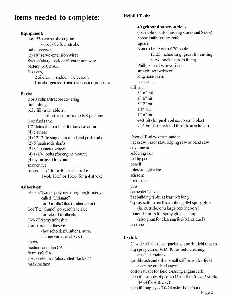
Items needed to complete:
Equipment:.46-.53 two stroke engine
or .63-.82 four strokeradio receiver(2) 18” servo extension wiresSwitch/charge jack or 6” extension wirebattery: 600 mAH5 servos, 2 aileron, 1 rudder, 1 elevator, 1 metal geared throttle servo if possible
Parts:2 or 3 rolls Ultracote coveringfuel tubingpoly fill (available at
fabric stores) for radio RX packing8 oz fuel tank1/2” latex foam rubber for tank isolation(4) clevises(4) 12” 2-56 single threaded end push rods(2) 5”push rods shafts(2) 3” diameter wheels(4) 1-1/4” bolts (for engine mount)(4) nylon insert lock-nutsspinner nutprops : 11x4 for a 40 size 2 stroke
14x4, 13x5 or 13x6 for a 4 stroke
Adhesives:Elmers “Nano” polyurethane glue (formerly
called “Ultimate”-or- Gorilla Glue (amber color)
Loc Tite “Sumo” polyurethane glue-or- clear Gorilla glue
3M-77 Spray adhesiveGoop brand adhesive
(household, plumber's, auto,marine varieties all OK)
epoxymedium and thin CAfoam safe CACA accelerator (also called “kicker”)masking tape
Helpful Tools:
40 grit sandpaper on block(available at auto finishing stores and Sears)hobby knife / utility knifesquareX-acto knife with # 26 blade
(2.25 inches long, great for cuttingservo pockets from foam)
Phillips head screwdriverstraight screwdriverlong nose pliershemostats
drill with:5/16" bit3/16” bit5/32” bit1/8" bit1/16” bit#48 bit (for push rod servo arm holes)#49 bit (for push rod throttle arm holes)
Dremel Tool w/ drum sanderhacksaw, razor saw, coping saw or band sawcovering ironsoldering ironfelt tip penpencilruler/straight edgescissorstoothpickspinscarpenter’s levelflat building table, at least 6 ft long“spray safe” area for applying 3M spray glue
(ie. outside, or a large box indoors)mineral spirits for spray glue cleanup
(also great for cleaning fuel/oil residue!)acetone
Useful:2" wide roll thin clear packing tape for field repairsbig spray can of WD-40 for field cleaning
crashed enginestoothbrush and other small stiff brush for field
cleaning crashed enginecotton swabs for field cleaning engine carbplentiful supply of props (11 x 4 for 40 size 2 stroke,
14x4 for 4 stroke)plentiful supply of 10-24 nylon bolts/nuts
Page 3
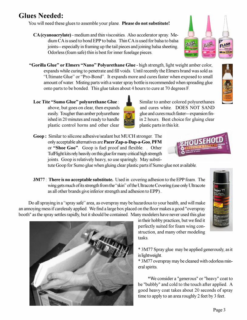
Glues Needed:You will need these glues to assemble your plane. Please do not substitute!
CA (cyanoacrylate) - medium and thin viscosities. Also accelerator spray. Me-dium CA is used to bond EPP to balsa. Thin CA is used for balsa to balsajoints-- especially in framing up the tail pieces and joining balsa sheeting.Odorless (foam safe) thin is best for inner fuselage pieces.
“Gorilla Glue” or Elmers “Nano” Polyurethane Glue - high strength, light weight amber color,expands while curing to penetrate and fill voids. Until recently the Elmers brand was sold as“Ultimate Glue” or “Pro-Bond”. It expands more and cures faster when exposed to smallamount of water. Misting parts with a water spray bottle is recommended when spreading glueonto parts to be bonded. This glue takes about 4 hours to cure at 70 degrees F.
Loc Tite “Sumo Glue” polyurethane Glue : Similar to amber colored polyurethanesabove, but goes on clear, then expands and cures white. DOES NOT SANDeasily. Tougher than amber polyurethane glue and cures much faster-- expansion fin-ished in 20 minutes and ready to handle in 2 hours. Best choice for gluing clearplastic control horns and other clear plastic parts in this kit.
Goop : Similar to silicone adhesive/sealant but MUCH stronger. Theonly acceptable alternatives are Pacer Zap-a-Dap-a-Goo, PFMor “Shoe Goo”. Goop is fuel proof and flexible. . OtherTufFlight kits rely heavily on this glue for many critical high strengthjoints. Goop is relatively heavy, so use sparingly. May substi-tute Goop for Sumo glue when gluing clear plastic parts if Sumo glue not available.
3M77 : There is no acceptable substitute. Used in covering adhesion to the EPP foam. Thewing gets much of its strength from the “skin” of the Ultracote Covering (use only Ultracoteas all other brands give inferior strength and adhesion to EPP)..
Do all spraying in a “spray safe” area, as overspray may be hazardous to your health, and will makean annoying mess if carelessly applied. We find a large box placed on the floor makes a good "overspraybooth" as the spray settles rapidly, but it should be contained. Many modelers have never used this glue
in their hobby practices, but we find itperfectly suited for foam wing con-struction, and many other modelingtasks.
* 3M77 Spray glue may be applied generously, as itis lightweight.* 3M77 overspray may be cleaned with odorless min-eral spirits.
*We consider a "generous" or "heavy" coat tobe "bubbly" and cold to the touch after applied. Agood heavy coat takes about 20 seconds of spraytime to apply to an area roughly 2 feet by 3 feet.
Page 4
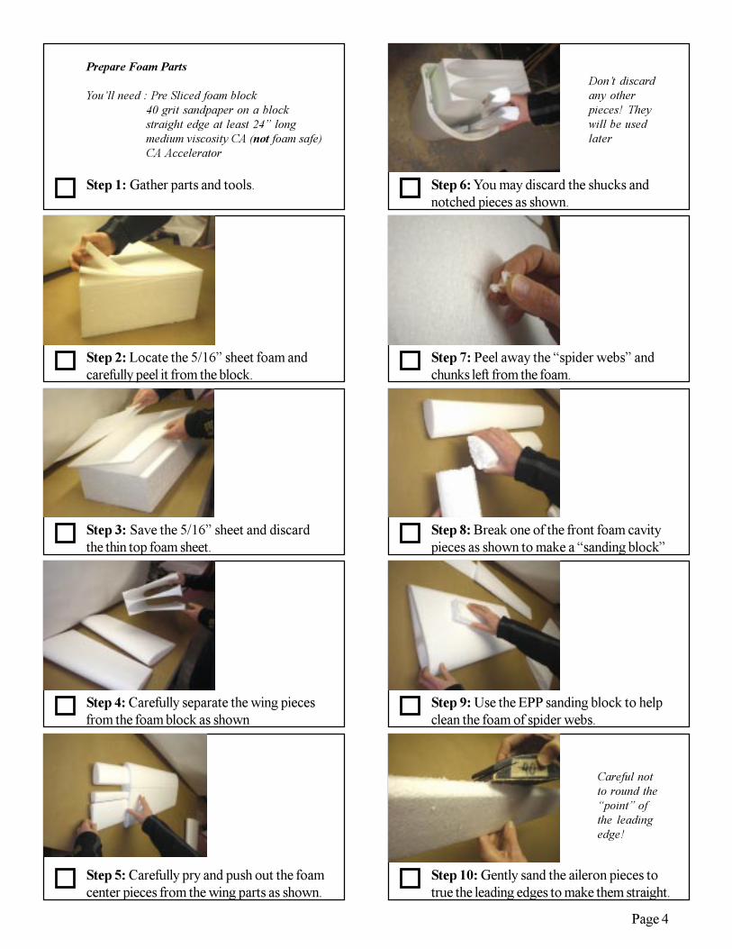
Step 5: Carefully pry and push out the foamcenter pieces from the wing parts as shown.
Step 4: Carefully separate the wing piecesfrom the foam block as shown
Step 3: Save the 5/16” sheet and discardthe thin top foam sheet.
Step 2: Locate the 5/16” sheet foam andcarefully peel it from the block.
Step 1: Gather parts and tools. Step 6: You may discard the shucks andnotched pieces as shown.
Step 7: Peel away the “spider webs” andchunks left from the foam.
Step 8: Break one of the front foam cavitypieces as shown to make a “sanding block”
Step 10: Gently sand the aileron pieces totrue the leading edges to make them straight.
Step 9: Use the EPP sanding block to helpclean the foam of spider webs.
Prepare Foam Parts
You’ll need : Pre Sliced foam block40 grit sandpaper on a blockstraight edge at least 24” longmedium viscosity CA (not foam safe)CA Accelerator
Careful notto round the“point” ofthe leadingedge!
Don’t discardany otherpieces! Theywill be usedlater

Page 5
Step 15: Gather parts and tools
Step 14: Now glue the rear split similar tothe front as shown.
Step 13: Place a straight edge on the wingand press down while spraying CA “kicker”
Step 12: Place and open the wing as shownto apply medium viscosity CA to the split.
Step 11: Open the “hinge” as shown andsand/clean these surfaces too as shown.
Step 16: Mark two of the spar pieces 2”from one end of each piece
Step 17: Cut off the ends at the 2” marks asshown (see next step)
Step 18: You should now have spar parts asshown above
Step 20: Draw lines to the center at theedge to make “points” tapered to 3” marks
Step 19: Now take these two spar piecesand mark one end 3” as shown.
Make and Assemble Spar pieces
You’ll need : (3) 1/32” plywood spar piecesruler, pencil, hobby knifefine line felt tip markersmall drafting square1/16 plastic spacer material
Place on atable edge toallow thewing to foldopen asshown
Make cutsperpendicularto edge asshown
It helps to skipahead to see whatyou’re workingtoward duringthese steps
Repeat forother winghalf whenboth frontand rearsplits havebeen glued
Page 6
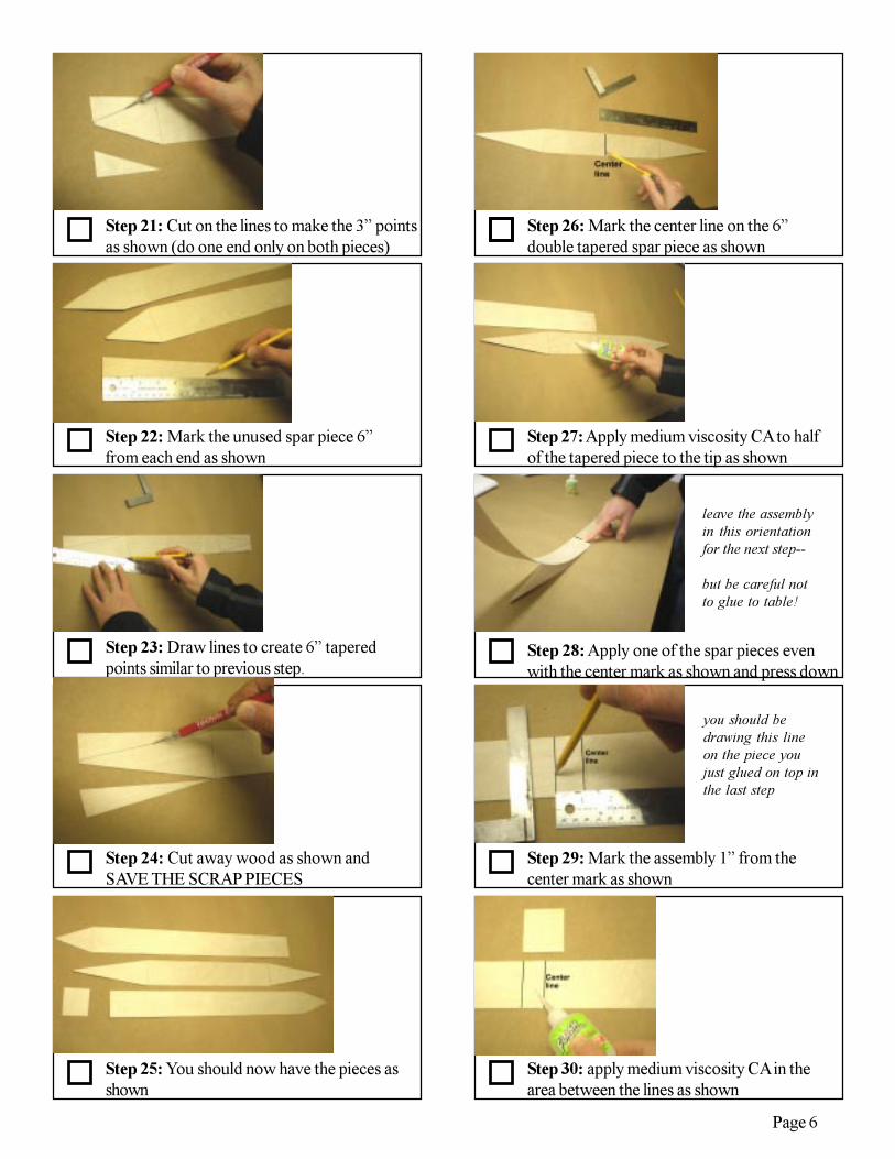
Step 25: You should now have the pieces asshown
Step 24: Cut away wood as shown andSAVE THE SCRAP PIECES
Step 23: Draw lines to create 6” taperedpoints similar to previous step.
Step 22: Mark the unused spar piece 6”from each end as shown
Step 21: Cut on the lines to make the 3” pointsas shown (do one end only on both pieces)
Step 26: Mark the center line on the 6”double tapered spar piece as shown
Step 27: Apply medium viscosity CA to halfof the tapered piece to the tip as shown
Step 28: Apply one of the spar pieces evenwith the center mark as shown and press down
Step 30: apply medium viscosity CA in thearea between the lines as shown
Step 29: Mark the assembly 1” from thecenter mark as shown
leave the assemblyin this orientationfor the next step--
but be careful notto glue to table!
you should bedrawing this lineon the piece youjust glued on top inthe last step

Page 7
Step 35: Locate the white plastic piece tothe 6” tapered spar end and trace as shown
Step 34: Mark the unglued spar piece 3/8”from the untapered edge as shown.
Step 33: Draw marks 3/8” from the centeron both sides of the center line.
Step 32: Mark the center line again on the2” piece applied on top in the last step.
Step 31: Apply the 2” piece as shown Step 36: Cut the white plastic to match thewood spar’s 6” tapered point
Step 37: Test fit the unglued spar into the“pocket” made in the previous steps
Step 38: The unglued spar fits into thepocket from the right in the above picture
Step 40: Mark the plastic piece where yousee the line 3/8” to the right of center as shown
Step 39: Apply the plastic piece exactly tothe 6” tapered spar end as shown
Note, half of this 2”piece should“overhang” andnot be glued toanything at thispoint
Make sure spar fitssnugly to theopposite piece asshown with nogaps.
Fix any interference
The plastic is semi-transparent.
Use a felt tipmarker
Don’t move theplastic piece for thenext step!
(Note, yourwhite plasticpiece willprobably belonger than theone shown.)
Page 8
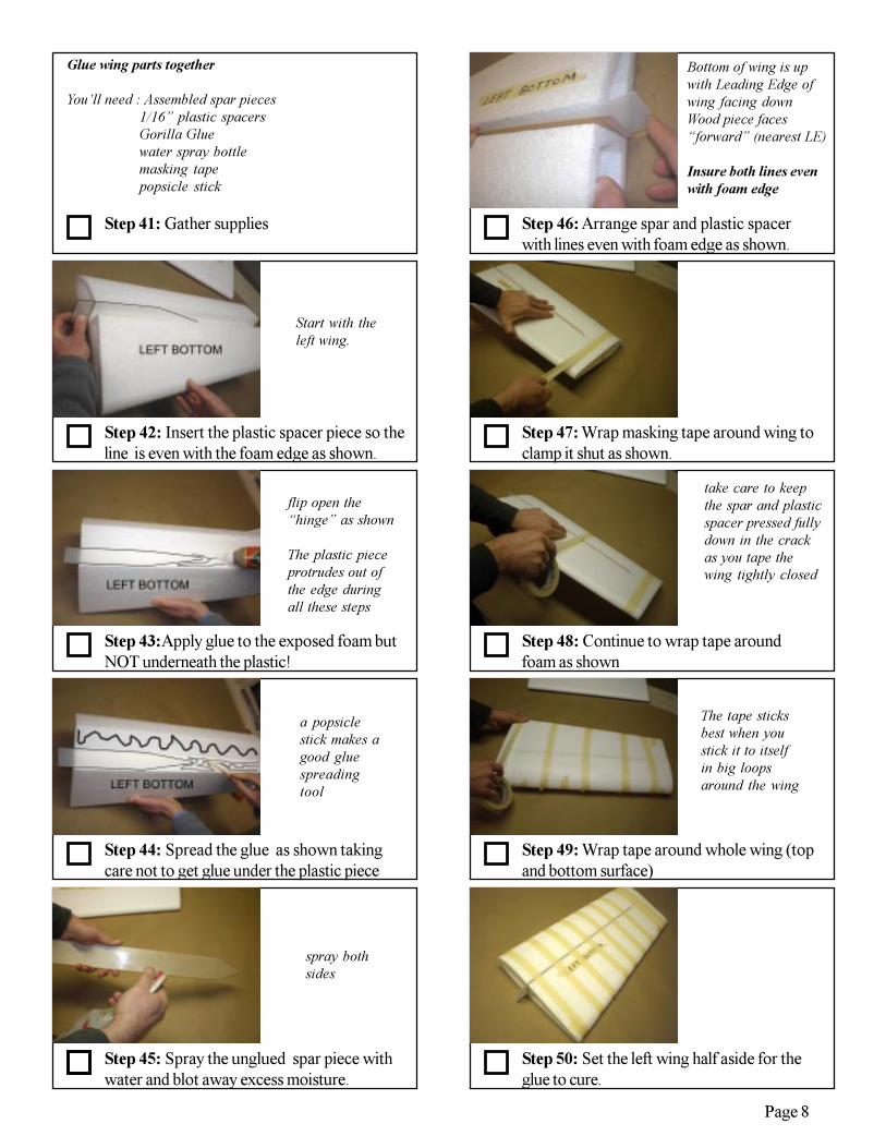
Step 46: Arrange spar and plastic spacerwith lines even with foam edge as shown.
Step 44: Spread the glue as shown takingcare not to get glue under the plastic piece
Step 43:Apply glue to the exposed foam butNOT underneath the plastic!
Step 42: Insert the plastic spacer piece so theline is even with the foam edge as shown.
Step 41: Gather supplies
Step 45: Spray the unglued spar piece withwater and blot away excess moisture.
Step 47: Wrap masking tape around wing toclamp it shut as shown.
Glue wing parts together
You’ll need : Assembled spar pieces1/16” plastic spacersGorilla Gluewater spray bottlemasking tapepopsicle stick
Bottom of wing is upwith Leading Edge ofwing facing downWood piece faces“forward” (nearest LE)
Insure both lines evenwith foam edge
Start with theleft wing.
flip open the“hinge” as shown
The plastic pieceprotrudes out ofthe edge duringall these steps
a popsiclestick makes agood gluespreadingtool
spray bothsides
Step 50: Set the left wing half aside for theglue to cure.
Step 49: Wrap tape around whole wing (topand bottom surface)
Step 48: Continue to wrap tape aroundfoam as shown
The tape sticksbest when youstick it to itselfin big loopsaround the wing
take care to keepthe spar and plasticspacer pressed fullydown in the crackas you tape thewing tightly closed

Page 9
Step 52: Spread glue with a popsicle stickor similar tool
Step 51: Open the right wing and applyGorilla glue to the entire opening as shown
Step 53: Spray water on the remaining sparpiece and blot away excess moisture
Step 54: Insert spar with the “pocket” facingforward aligned to the foam edge as shown
Step 55: Tape the right wing like the left halfand set it aside for the glue to cure.
Step 60: Cut out the foam parts with ahobby knife that has a new SHARP blade.
Step 59: Apply the template to the foamsheet
spray bothsides of thelonger endup to themarks nearthe center
The 3rd markshould beeven with thefoam
Step 56: Gather parts and tools.
Step 57: Cut the full size foam templatesheet as shown
Step 58: Lightly spray the backside of thetemplate with 3M77
Make foam tail feathers
You’ll need : 5/16” foam sheet, medium CA, kickerruler, pencil, hobby knife, 3M77balsa tri stock, carbon elevator tubeRobart hinges, template sheethand drill 1/16”, 1/8” and 5/32” bits
Keep theparts grouptogether -- itfits the foamexactly in thenext steps
Page 10
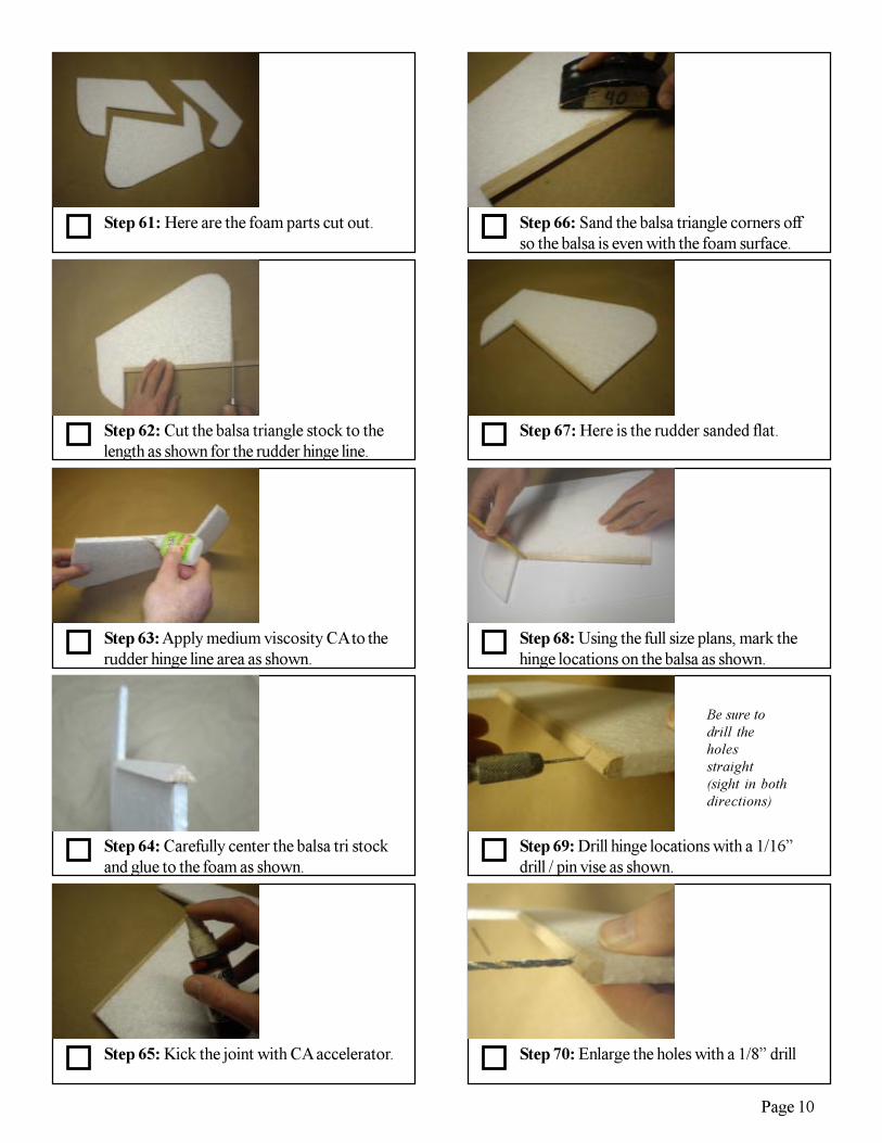
Step 65: Kick the joint with CA accelerator.
Step 64: Carefully center the balsa tri stockand glue to the foam as shown.
Step 63: Apply medium viscosity CA to therudder hinge line area as shown.
Step 62: Cut the balsa triangle stock to thelength as shown for the rudder hinge line.
Step 61: Here are the foam parts cut out. Step 66: Sand the balsa triangle corners offso the balsa is even with the foam surface.
Step 67: Here is the rudder sanded flat.
Step 68: Using the full size plans, mark thehinge locations on the balsa as shown.
Step 70: Enlarge the holes with a 1/8” drill
Step 69: Drill hinge locations with a 1/16”drill / pin vise as shown.
Be sure todrill theholesstraight(sight in bothdirections)

Page 11
Step 75: The hinge will fit as shown. Repeatfor all holes on one side of the carbon tube.
Step 74: With a 5/32” drill, enlarge ONEside wall only!
Step 73: Fit a hinge into the carbon tube andnotice it will not slide down all the way.
Step 72: Test fit the hinge and cut the balsaas necessary for a good fit as shown.
Step 71: Use a hobby knife to carve out thebalsa so a hinge will fit inside.
Step 76: Use a hinge in the tube to see whichside will be glued to the foam elevators
Step 79: Rotate and align the tube so a testhinge points to the foam in the next step
Step 77: Place the tube in the foam eleva-tors on the plans as shown
Step 80: Glue the tube to the foam withmedium CA.
Step 78: Insure the foam is lined up so it leavesa small gap to the horiz stab on the plans.
Repeatprocess forall rudderhinge holes
Only elevator plansshown for clarity
“horiz stab” is shortfor “horizontalstab”
Trim the foam so thetube has a snug fit
Center the tube withinthe foam thickness
(do one half at a timewith a hinge in theother half as above foralignment)

Page 12
Step 85: Measure and mark the balsa sticksover the plan.
Step 84: Cover the plans with plastic wrap
Step 83: Gather parts and tools
Step 82: Glue other half to match the firsthalf (lay on table to help alignment)
Step 81: Kick the CA taking care to keepthe tube centered and aligned to the foam.
Step 86: Cut the sticks to the correct length.
Step 87: Lay the sticks over the plan in thecorrect position and pin to hold them down
Step 88: Glue sticks together with CARepeat process for entire stab.
Step 90: Glue the center block as shown.
Step 89: Using the full size template, makethe center stab block (see below)
Make balsa tail stabilizers
You’ll need : 5/16” sq balsa sticks, 5/16” sheet thin/ medium CA, kicker, pinsruler, pencil, hobby knife, razor sawbalsa tri stock, plastic wraphand drill 1/16”, 1/8” and 5/32” bitssanding block, full size plans / templateelevator assembly
Onlyhorizontalstab shownfor clarity
Cut thelongestpieces firstthen workyour way tothe nextshorter ones.
It’s oftenwiser to cut alittle long,and slowlysand to thecorrectlength andangle

Page 13
Step 95: Round the leading edges only ofeach stab.
Step 94: Sand the edges even and surfacesflat on both stabs.
Step 93: Glue tri stock to the stab as shown.
Step 92: Cut tri stock to fit the rear of thehorizontal stab and apply centered as shown.
Step 91: Make the vertical stab in similarfashion.
Step 96: Use the elevator assembly to markthe horiz stab hinge locations at each hole.
Step 97: Mark hinge hole locations withsmall drill or prick punch.
Step 98: Drill 1/8”hole in at all hinge loca-tions as shown.
Step 100: Enlarge hole with drill to depth asshown.
Step 99: With a 5/32” drill, use maskingtape as a “depth gauge” to 11/16”
Apply tri stockONLY to the horizstab for now!
(Vertical stab willget glued later)
Center thestab withinthe elevatorassembly(gaps onsides shouldbe equal)
This is an alternateapproach to usinga hobby knife asdone whenenlarging rudderhinge holes. Youcan use eithermethod here.

Page 14
Step 105: When glue has fully cured,remove masking tape from wing halves.
Step 104: Gather parts and tools
Step 103: Once satisfied, trim foam to beeven with balsa stab as shown.
Step 102: Test fit hinges in stab and elevatorsimultaneously. Trim/ adjust as needed.
Step 101: Test fit hinge. Trim with knife asneeded.
Step 106: Using 40 grit sandpaper, sand thewing bottom spar areas flush with surface
Step 107: Sand the top spar areas also toclear any glue which squirted out.
Step 108: Carefully trim the root edge areasto remove any glue bumps with hobby knife.
Step 110: Mark both wing bottoms 7” fromthe root edge at the spar as shown.
Step 109: Using the full size plans/template,trim both wing panel tip edges as shown.
Hinge pivot pointcenter should bealigned with tristock point, andfree to move up anddown as shown.
a gap of 1/16”between balsa andcarbon is desired.Hinge pivotsshould all becentered in this gap
Prepare Foam Wings
You’ll need :assembled foam wings40 grit sandpaper on sanding blockfull size plans / templatethrottle and aileron servos, pliersgorilla glue, masking tape
Don’t cut into thewood spars! Justtrim any glue whichis in the corners.
Trim both wing rootedges.
A band saw is bestfor this, but you canuse a sharp knifetoo with patience.
Sand contoursmooth with 40 gritpaper on a block.
This marks theinner location ofthe aileron servo

Page 15
Step 115: Mark the right wing bottom 1”from the root edge along the spar as shown
Step 114: Apply gorilla glue to the cavityand moisture and tape servo in place.
Step 113: A Dremel tool with drum sanderhelps remove foam to the correct depth.
Step 112: Use pliers to pull foam to create acavity for the servo
Step 111: Trace around and cut the outlineof servo as shown with a sharp knife.
Step 116: trace around the throttle servolocation as shown (metal gears recommended)
Step 117: Mount the throttle servo in thesame fashion as the aileron servos.
Step 118: This is a view looking inside theright wing root.
Step 120: Insert the foam piece into the wingtip until it stops and trace the edge as shown
Step 119: Retrieve the front wing cavitycore pieces
Aileron servos willsit directly in frontof the spar with thewire pointing to theroot edge as shown
Make recesses for theservo lugs too.
Test fit servo to checkthe fit. The hole depthis good when the servobody top is even withthe foam surface.
Be sure this is theRIGHT WINGBOTTOM!
The Throttle Servo willsit directly in front ofthe spar with the wirepointing to the rootedge as shown
repeat for left wingalso
Look ahead to seeinside view of servowires to comparewith your wing.
Push the foam untilit fits snugly

Page 16
Step 125: Tape the tip caps flush with theedges as shown. Set aside to cure.
Step 124: Glue the foam cap pieces insidethe tip cavities as shown with poly u glue.
Step 123: From a scrap of 5/16” foam, cuta wedge which fits inside rear tip cavity
Step 122: Using a band saw sharp knife,slice this section from the foam piece.
Step 121: Pull the foam out 1/2” and tracethe outline again as shown
Step 127: Once glue has cured, temporarilyremove the white plastic spacer piece.
Repeat for bothwing tips
We want to break itfree of the poly-uglue that may haveexpanded into thegroove
Watch your fingers!
Step 126: Sand both foam tips to make thesurfaces flat and even using 40 grit.
Step 128: Mark 3/4” from the root edge ofthe left wing panel along the spar as shown
Step 129: Slice between the wood and foam tothe 3/4” mark on both sides of the spar.
Step 130: Insert the right spar where theplastic spacer was and press halves together
A long thin hobbyknife works besthere
Be careful not tocut into the woodspar
The left spar protrusionshould fit into thespar“pocket”
The spar “pocket”protrusion should fitinto the slice from thelast step
Page 17
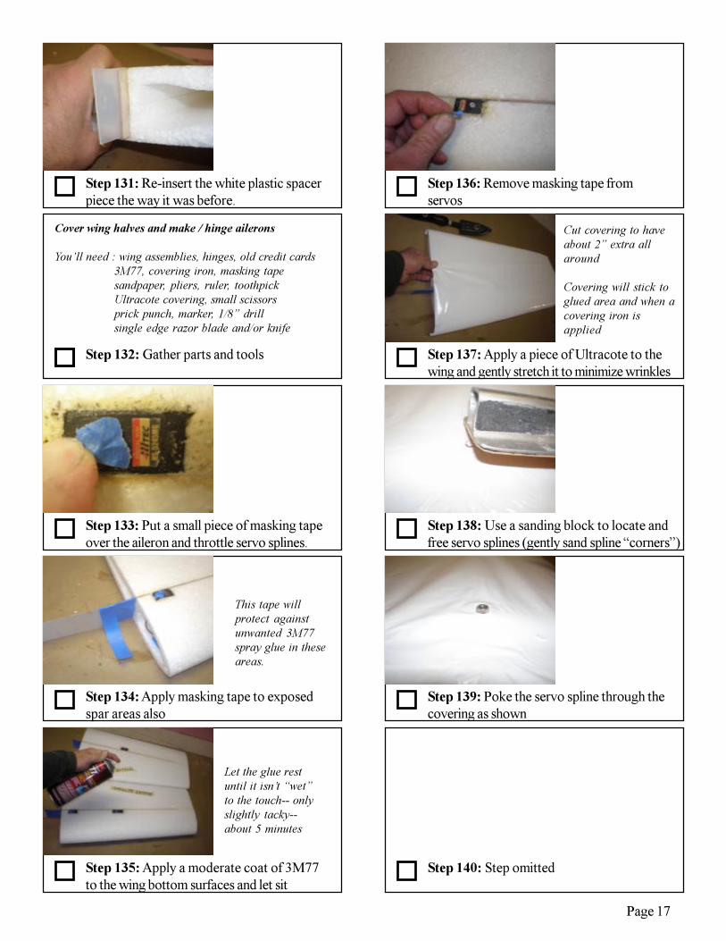
Step 135: Apply a moderate coat of 3M77to the wing bottom surfaces and let sit
Let the glue restuntil it isn’t “wet”to the touch-- onlyslightly tacky--about 5 minutes
Step 132: Gather parts and tools
Step 131: Re-insert the white plastic spacerpiece the way it was before.
Step 134: Apply masking tape to exposedspar areas also
Step 133: Put a small piece of masking tapeover the aileron and throttle servo splines.
Cover wing halves and make / hinge ailerons
You’ll need : wing assemblies, hinges, old credit cards3M77, covering iron, masking tapesandpaper, pliers, ruler, toothpickUltracote covering, small scissorsprick punch, marker, 1/8” drillsingle edge razor blade and/or knife
This tape willprotect againstunwanted 3M77spray glue in theseareas.
Step 139: Poke the servo spline through thecovering as shown
Step 138: Use a sanding block to locate andfree servo splines (gently sand spline “corners”)
Step 137: Apply a piece of Ultracote to thewing and gently stretch it to minimize wrinkles
Step 136: Remove masking tape fromservos
Cut covering to haveabout 2” extra allaround
Covering will stick toglued area and when acovering iron isapplied
Step 140: Step omitted

Page 18
Step 150: Mark outline of aileron as shown
Step 149: Apply template over foam aileronpieces as shown
Step 148: Copy / cut full size paper tem-plates for the ailerons
Step 147: Remove white plastic piecespermanently.
Step 146: Iron all surfaces to minimizewrinkles.
Set Irontemperature to~300 deg F
Step 141: Iron around the servo spline tominimize wrinkles
Step 142: Once wrinkles are minimized, ironedges and trim leaving about 1/4” overhang
Step 143: Iron edges only at this point!
Step 145: Apply covering to the top and tipsurfaces and trim neatly
Step 144: Apply masking tape to coveringedges and spray 3M77 to wing top and tip
iron temperatureshould be about250 degrees F
After this step is agood time to cleanthe iron withmineral spirits and/or acetone
We need to mask areaswhere covering willoverlap to itself (LE,TE , root and tip edges)
Let the glue sit 5minutes and removetape

Page 19
Step 160: Drill the hinge holes ~1” deepwith a 1/8” drill
Step 159: Poke a hole in all hinge locationswith a prick punch as shown
Step 158: Insure both aileron markings aresymmetrical
Step 157: Mark location of control horn onaileron bottom as shown
Step 156: Use full size plans to transferhinge locations to wing and aileron as shown
Ailerons are heldwith fat edgesfacing togetherhere
Step 151: Trim root, tip and trailing edges ofailerons with sharp hobby knife
Step 152: Use a ruler to trim the trailingedge as shown
Step 153: Spray one side of aileron with3M77 and allow to sit 5 minutes
Step 155: Carefully iron both sides takingcare to keep aileron straight
Step 154: Apply Ultracote covering to gluedside and follow the wing covering procedure
be sure to holdaileron STRAIGHTduring this step
(check leadingedge with anotherruler)
Warning:Do NOT iron oneside surface untilboth sides arecovered.
If aileron curvesduring this step,gently bend todesired shape whileheating, thenremove iron and letcool until straight
Page 20
Step 169: Gather parts and tools.
Step 168: Insert 2 credit cards to preservethe gap while the glue dries
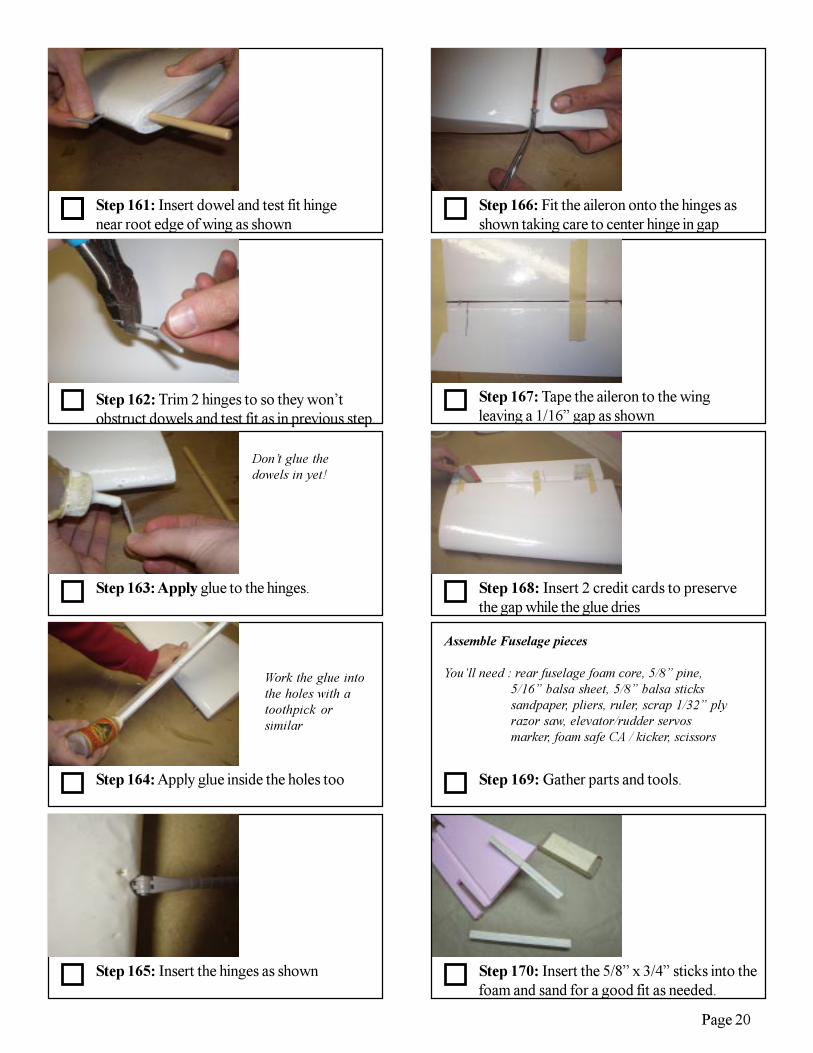
Step 167: Tape the aileron to the wingleaving a 1/16” gap as shown
Step 166: Fit the aileron onto the hinges asshown taking care to center hinge in gap
Assemble Fuselage pieces
You’ll need : rear fuselage foam core, 5/8” pine,5/16” balsa sheet, 5/8” balsa stickssandpaper, pliers, ruler, scrap 1/32” plyrazor saw, elevator/rudder servosmarker, foam safe CA / kicker, scissors
Step 161: Insert dowel and test fit hingenear root edge of wing as shown
Step 162: Trim 2 hinges to so they won’tobstruct dowels and test fit as in previous step.
Step 163: Apply glue to the hinges.
Step 165: Insert the hinges as shown
Step 164: Apply glue inside the holes too
Don’t glue thedowels in yet!
Work the glue intothe holes with atoothpick orsimilar
Step 170: Insert the 5/8” x 3/4” sticks into thefoam and sand for a good fit as needed.

Page 21
Step 175: Cut two 5/8” basswood sticks tofit between the balsa where shown
Step 174: Cut and glue 5/8”balsa stickswhere shown (top and bottom)
Step 173: Cut 5/8” balsa sticks to length andglue as shown. Repeat for upper piece also.
Sticks fromlast stepnot shown
Step 171: Cut the sticks even with the foam asshown.
Step 172: Glue the sticks in place with foamsafe CA and kicker.
Step 176: Glue the rearward basswoodstick as shown with foam safe CA
Step 177: Use elevator servo and basswoodstick to size the hole for servo as shown.
Step 178: Remove foam with a sharp knife
Step 180: With a dremel tool, grind thebasswood rail even with the channel in foam
Step 179: Glue the front basswood stick inplace with foam safe CA
Leave about 3/32”gap on each side ofservo to basswood
(mark foam atcorrect size for thecavity)
The foam channel is onthe right side of thefuse. (This is where theservo wires are routedforward)
A knife or file may alsobe used
Page 22
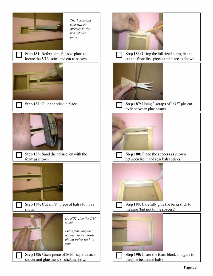
Step 185: Use a piece of 5/16” sq stick as aspacer and glue the 5/8” stick as shown
Step 184: Cut a 5/8” piece of balsa to fit asshown
Step 183: Sand the balsa even with thefoam as shown.
Step 182: Glue the stick in place
Step 181: Refer to the full size plans tolocate the 5/16” stick and cut as shown.
The horizontalstab will sitdirectly to therear of thispiece
Do NOT glue the 5/16”stick!
Press foam togetheragainst spacer whilegluing balsa stick atrear
Step 186: Using the full sized plans, fit andcut the front fuse pieces and place as shown
Step 187: Using 3 scraps of 1/32” ply, cutto fit between pine beams
Step 190: Insert the foam block and glue tothe pine beam and balsa
Step 188: Place the spacers as shownbetween front and rear balsa sticks
Step 189: Carefully glue the balsa stick tothe pine (but not to the spacers)
Page 23
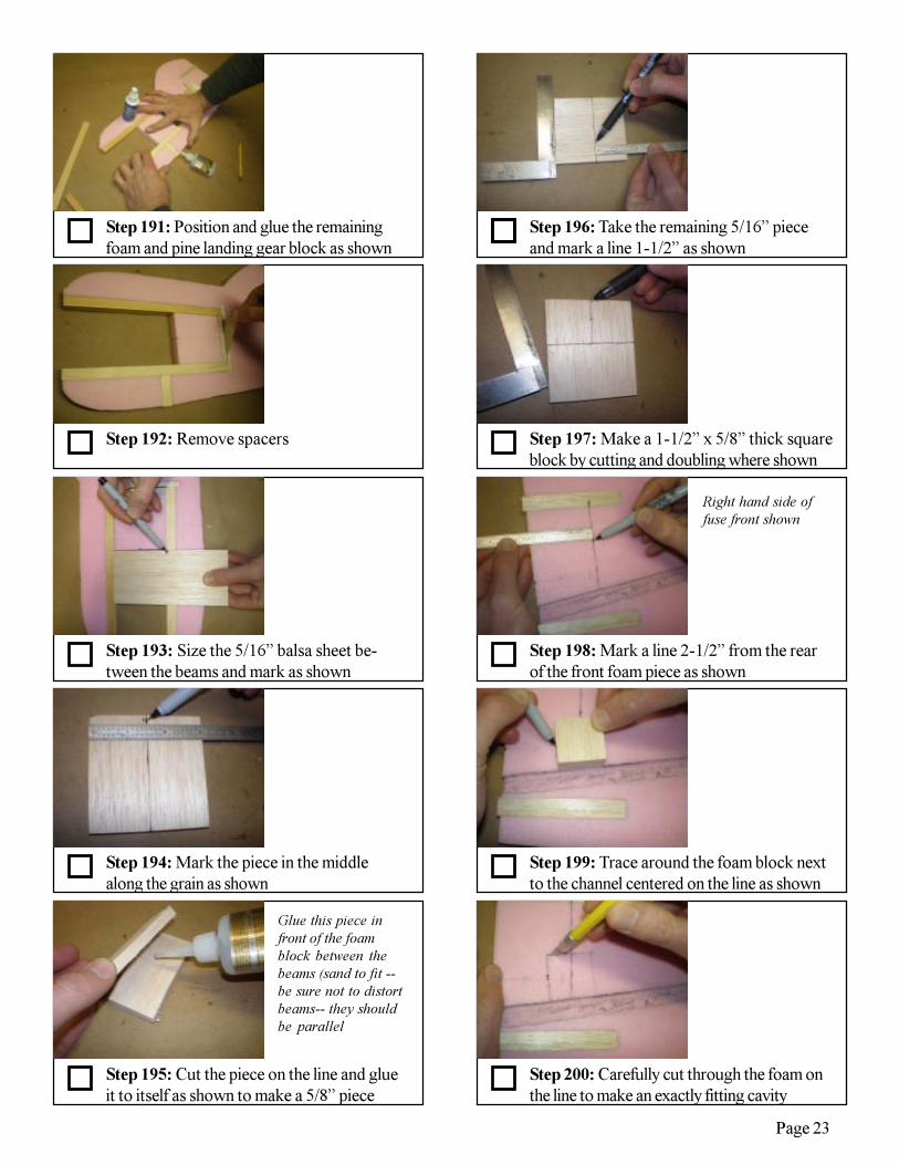
Step 195: Cut the piece on the line and glueit to itself as shown to make a 5/8” piece
Step 194: Mark the piece in the middlealong the grain as shown
Step 193: Size the 5/16” balsa sheet be-tween the beams and mark as shown
Step 192: Remove spacers
Step 191: Position and glue the remainingfoam and pine landing gear block as shown
Glue this piece infront of the foamblock between thebeams (sand to fit --be sure not to distortbeams-- they shouldbe parallel
Step 196: Take the remaining 5/16” pieceand mark a line 1-1/2” as shown
Step 197: Make a 1-1/2” x 5/8” thick squareblock by cutting and doubling where shown
Step 198: Mark a line 2-1/2” from the rearof the front foam piece as shown
Step 200: Carefully cut through the foam onthe line to make an exactly fitting cavity
Step 199: Trace around the foam block nextto the channel centered on the line as shown
Right hand side offuse front shown
Page 24
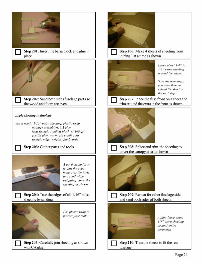
Step 204: True the edges of all 1/16” balsasheeting by sanding
Step 203: Gather parts and tools
Step 202: Sand both sides fuselage parts sothe wood and foam are even
Step 201: Insert the balsa block and glue inplace
Apply sheeting to fuselage
You’ll need : 1/16” balsa sheeting, plastic wrapfuselage assemblies, CA gluelong straight sanding block w/ 100 gritgorilla glue, water, old credit cardstraight edge, weights, flat boards
A good method is tolet just the edgehang over the tableand sand whileweighting down thesheeting as shown
Step 205: Carefully join sheeting as shownwith CA glue.
Use plastic wrap toprotect your table!
Step 210: Trim the sheets to fit the rearfuselage
Again, leave about1/4” extra sheetingaround entireperimeter.
Step 206: Make 4 sheets of sheeting fromjoining 3 at a time as shown.
Step 207: Place the fuse front on a sheet andtrim around the extra in the front as shown
Step 209: Repeat for other fuselage sideand sand both sides of both sheets.
Step 208: Splice and trim the sheeting tocover the canopy area as shown
Leave about 1/4” to1/2” extra sheetingaround the edges.
Save the trimmings,you need them toextend the sheet inthe next step

Page 25

Page 26

Page 27

Page 28
Page 29
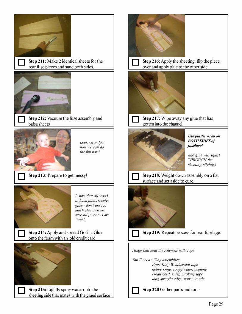
Step 214: Apply and spread Gorilla Glueonto the foam with an old credit card
Step 213: Prepare to get messy!
Step 212: Vacuum the fuse assembly andbalsa sheets
Step 211: Make 2 identical sheets for therear fuse pieces and sand both sides.
Look Grandpa,now we can dothe fun part!
Insure that all woodto foam joints receiveglue-- don’t use toomuch glue, just besure all junctions are“wet”.
Step 215: Lightly spray water onto thesheeting side that mates with the glued surface
Step 220 Gather parts and tools
Step 216: Apply the sheeting, flip the pieceover and apply glue to the other side
Step 217: Wipe away any glue that hasgotten into the channel.
Step 219: Repeat process for rear fuselage.
Step 218: Weight down assembly on a flatsurface and set aside to cure.
Use plastic wrap onBOTH SIDES offuselage!
(the glue will squirtTHROUGH thesheeting slightly)
Hinge and Seal the Ailerons with Tape
You’ll need : Wing assembliesFrost King Weatherseal tapehobby knife, soapy water, acetonecredit card, ruler, masking tapelong straight edge, paper towels
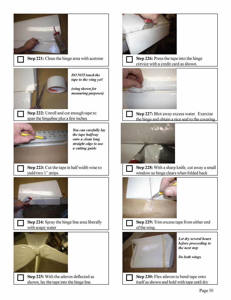
Page 30
Step 221: Clean the hinge area with acetone
Step 222: Unroll and cut enough tape tospan the hingeline plus a few inches
Step 224: Spray the hinge line area liberallywith soapy water
Step 223: Cut the tape in half width wise toyield two 1” strips.
DO NOT touch thetape to the wing yet!
(wing shown formeasuring purposes)
You can carefully laythe tape halfwayonto a clean longstraight edge to usea cutting guide
Step 225: With the aileron deflected asshown, lay the tape into the hinge line.
Step 229: Trim excess tape from either endof the wing.
Step 228: With a sharp knife, cut away a smallwindow so hinge clears when folded back
Step 227: Blot away excess water. Exercisethe hinge and obtain a nice seal to the covering.
Step 226: Press the tape into the hingecrevice with a credit card as shown.
Step 230: Flex aileron to bend tape ontoitself as shown and hold with tape until dry
Let dry several hoursbefore proceeding tothe next step
Do both wings.
Page 31
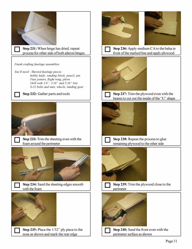
Step 231: When hinge has dried, repeatprocess for other side of both aileron hinges.
Step 232: Gather parts and tools
Step 233: Trim the sheeting even with thefoam around the perimeter
Finish crafting fuselage assemblies
You’ll need : Sheeted fuselage pieceshobby knife, sanding block, pencil, pinFuse joiners, Right wing, pliersDrill with 1/8”, 3/16” and 5/16” bits6-32 bolts and nuts, wheels, landing gear
Step 235: Place the 1/32” ply piece to thenose as shown and mark the rear edge
Step 234: Sand the sheeting edges smoothwith the foam
Step 238: Repeat the process to glueremaining plywood to the other side
Step 237: Trim the plywood even with thebeams to cut out the inside of the “U” shape
Step 236: Apply medium CA to the balsa infront of the marked line and apply plywood
Step 239: Trim the plywood close to theperimeter
Step 240: Sand the front even with theperimeter surface as shown
Page 32
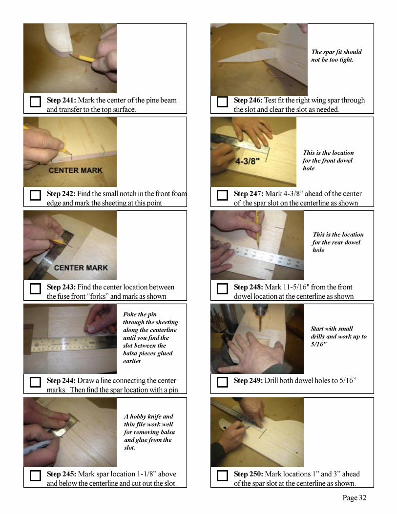
Step 241: Mark the center of the pine beamand transfer to the top surface.
Step 242: Find the small notch in the front foamedge and mark the sheeting at this point
Step 243: Find the center location betweenthe fuse front “forks” and mark as shown
Step 244: Draw a line connecting the centermarks. Then find the spar location with a pin.
Step 245: Mark spar location 1-1/8” aboveand below the centerline and cut out the slot.
Step 247: Mark 4-3/8” ahead of the centerof the spar slot on the centerline as shown
Step 246: Test fit the right wing spar throughthe slot and clear the slot as needed.
Poke the pinthrough the sheetingalong the centerlineuntil you find theslot between thebalsa pieces gluedearlier
A hobby knife andthin file work wellfor removing balsaand glue from theslot.
The spar fit shouldnot be too tight.
This is the locationfor the front dowelhole
Step 250: Mark locations 1” and 3” aheadof the spar slot at the centerline as shown.
Step 249: Drill both dowel holes to 5/16”
Step 248: Mark 11-5/16" from the frontdowel location at the centerline as shown
This is the locationfor the rear dowelhole
Start with smalldrills and work up to5/16”
Page 33
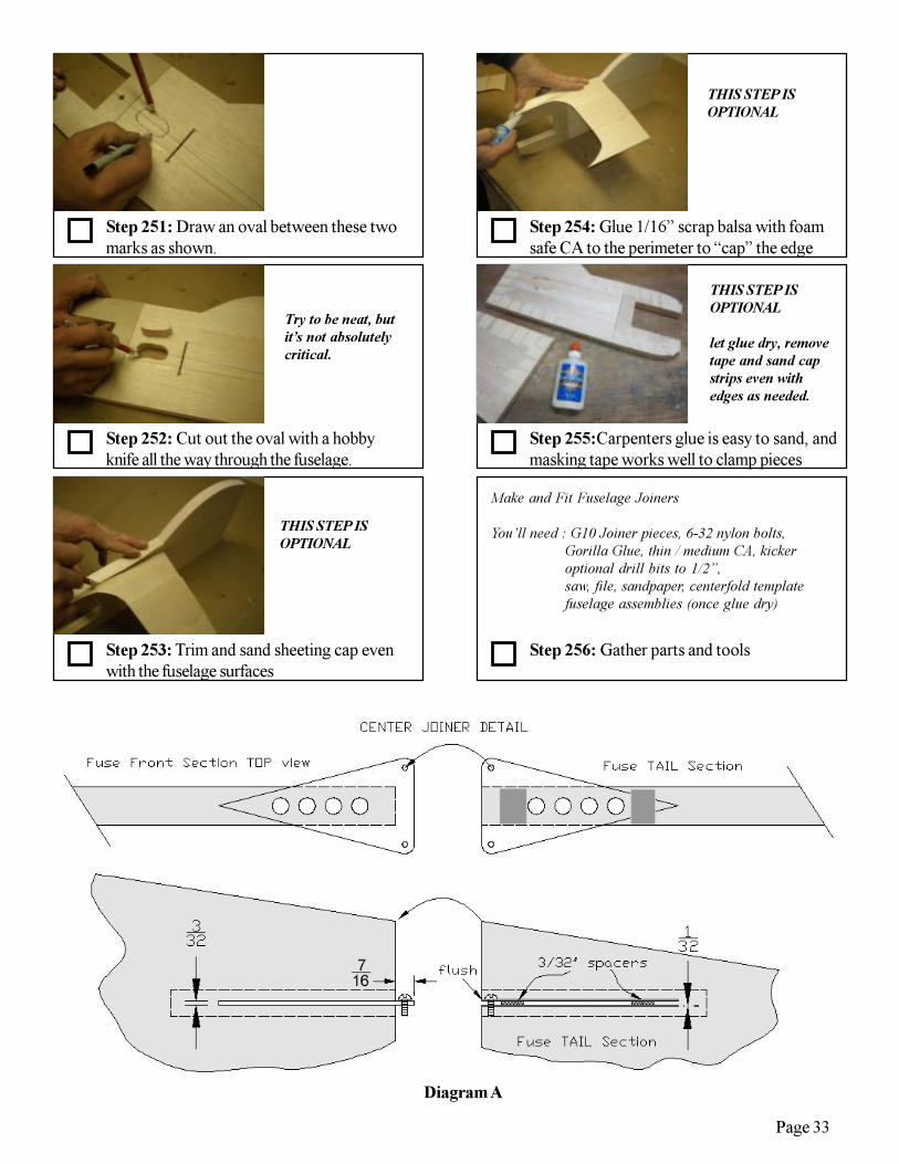
Step 252: Cut out the oval with a hobbyknife all the way through the fuselage.
Step 251: Draw an oval between these twomarks as shown.
Try to be neat, butit’s not absolutelycritical.
Step 253: Trim and sand sheeting cap evenwith the fuselage surfaces
THIS STEP ISOPTIONAL
Step 254: Glue 1/16” scrap balsa with foamsafe CA to the perimeter to “cap” the edge
THIS STEP ISOPTIONAL
Step 255:Carpenters glue is easy to sand, andmasking tape works well to clamp pieces
THIS STEP ISOPTIONAL
let glue dry, removetape and sand capstrips even withedges as needed.
Step 256: Gather parts and tools
Make and Fit Fuselage Joiners
You’ll need : G10 Joiner pieces, 6-32 nylon bolts,Gorilla Glue, thin / medium CA, kickeroptional drill bits to 1/2”,saw, file, sandpaper, centerfold templatefuselage assemblies (once glue dry)
Diagram A
Page 34
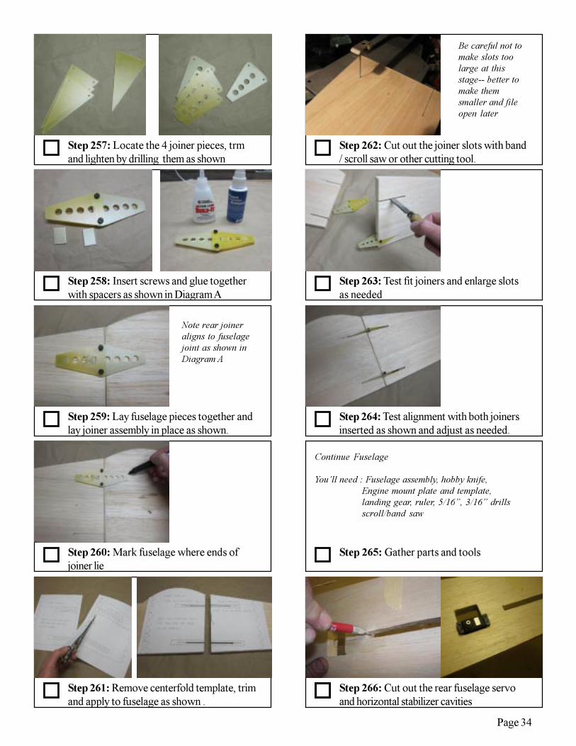
Step 260: Mark fuselage where ends ofjoiner lie
Step 259: Lay fuselage pieces together andlay joiner assembly in place as shown.
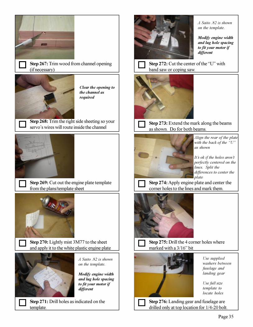
Step 262: Cut out the joiner slots with band/ scroll saw or other cutting tool.
Step 261: Remove centerfold template, trimand apply to fuselage as shown .
Step 257: Locate the 4 joiner pieces, trmand lighten by drilling them as shown
Step 258: Insert screws and glue togetherwith spacers as shown in Diagram A
Note rear joineraligns to fuselagejoint as shown inDiagram A
Be careful not tomake slots toolarge at thisstage-- better tomake themsmaller and fileopen later
Step 264: Test alignment with both joinersinserted as shown and adjust as needed.
Step 263: Test fit joiners and enlarge slotsas needed
Step 265: Gather parts and tools
Continue Fuselage
You’ll need : Fuselage assembly, hobby knife,Engine mount plate and template,landing gear, ruler, 5/16”, 3/16” drillsscroll/band saw
Step 266: Cut out the rear fuselage servoand horizontal stabilizer cavities
Page 35
Step 272: Cut the center of the “U” withband saw or coping saw.
A Saito .82 is shownon the template.
Modify engine widthand lug hole spacingto fit your motor ifdifferent
Step 269: Cut out the engine plate templatefrom the plans/template sheet
Step 271: Drill holes as indicated on thetemplate.
Step 270: Lightly mist 3M77 to the sheetand apply it to the white plastic engine plate
A Saito .82 is shownon the template.
Modify engine widthand lug hole spacingto fit your motor ifdifferent
Step 268: Trim the right side sheeting so yourservo’s wires will route inside the channel
Clear the opening tothe channel asrequired
Step 267: Trim wood from channel opening(if necessary)
Step 275: Drill the 4 corner holes wheremarked with a 3/16” bit
Step 274: Apply engine plate and center thecorner holes to the lines and mark them.
Step 273: Extend the mark along the beamsas shown. Do for both beams.
Align the rear of the platewith the back of the “U”as shown
It’s ok if the holes aren’tperfectly centered on thelines. Split thedifferences to center theplate
Step 276: Landing gear and fuselage aredrilled only at top location for 1/4-20 bolt.
Use suppliedwashers betweenfuselage andlanding gear
Use full sizetemplate tolocate holes

Page 36
Step 278: Drill the axle with a 1/8” hole tofit the supplied 6-32 bolt.
The wheels run on 6-32bolt axles held to thegear with 2 nuts-- oneon either side of thegear. Install and useloc-tite
Step 277: A 5/16” dowel and rubber bandsprovide bottom “shock absorber:”
Step 279: Gather parts and tools
Make and fit Stabilizers
You’ll need : 5/16” balsa sticks, CA, Kicker, rulerhobby knife, rear fuselage assembly,horizontal stabilizersGorilla Glue
Step 282: Test fit the stab into the groove
Step 280: Position the vertical stab on thefuselage rear and trace the sides as shown
Align stab centeredwithin fuselage width
Step 281: Measure 5/16” down from thetop and dig a groove this deep between lines
Step 283: Place stab into the groove, andglue to triangle stock with thin CA.
Step 286: Glue triangle stock centered onthe rear fuse as shown with medium CA
Step 285: Cut balsa triangle stock to lengthas shown
Step 284: Check alignment with ruler andadjust groove if needed for a good fit
Glue even with fusebottom and let theextra protrude upwardfor now
Be sure it’s straightand centered!
Page 37
Step 295: Gather parts and tools
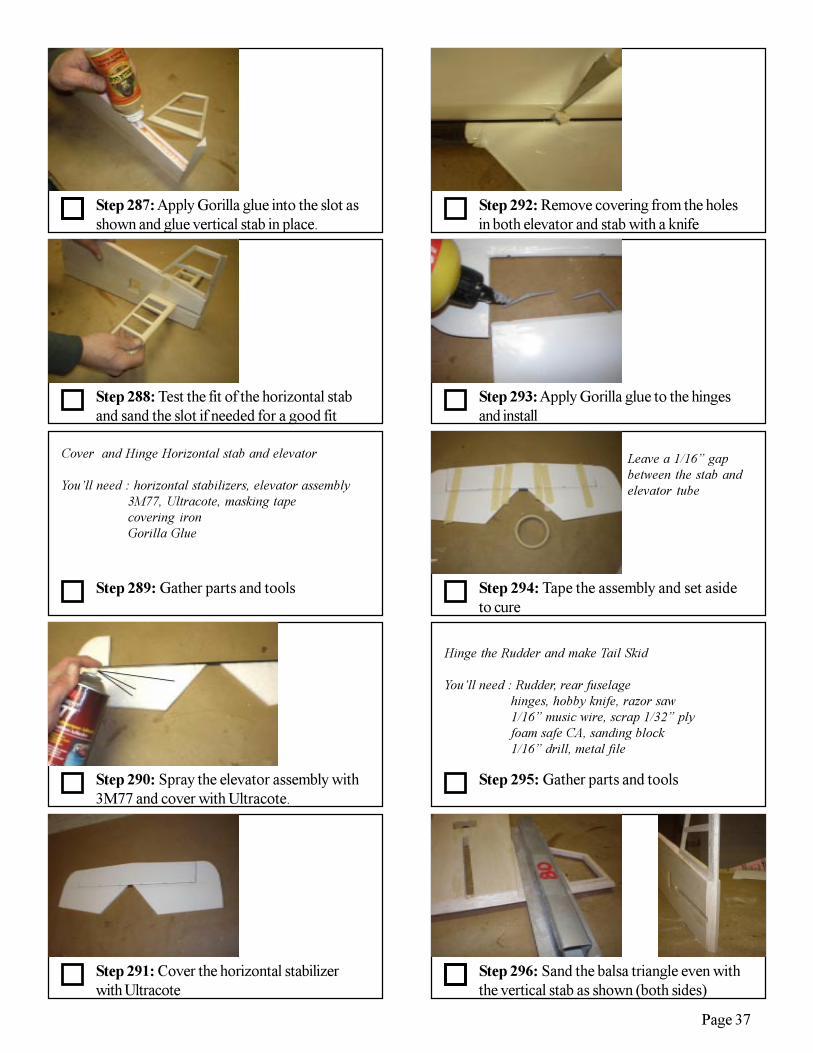
Step 294: Tape the assembly and set asideto cure
Step 293: Apply Gorilla glue to the hingesand install
Step 292: Remove covering from the holesin both elevator and stab with a knife
Step 296: Sand the balsa triangle even withthe vertical stab as shown (both sides)
Leave a 1/16” gapbetween the stab andelevator tube
Hinge the Rudder and make Tail Skid
You’ll need : Rudder, rear fuselagehinges, hobby knife, razor saw1/16” music wire, scrap 1/32” plyfoam safe CA, sanding block1/16” drill, metal file
Step 288: Test the fit of the horizontal staband sand the slot if needed for a good fit
Step 290: Spray the elevator assembly with3M77 and cover with Ultracote.
Step 289: Gather parts and tools
Cover and Hinge Horizontal stab and elevator
You’ll need : horizontal stabilizers, elevator assembly3M77, Ultracote, masking tapecovering ironGorilla Glue
Step 287: Apply Gorilla glue into the slot asshown and glue vertical stab in place.
Step 291: Cover the horizontal stabilizerwith Ultracote

Page 38
Step 305: Insert the grooved end into thehole to test fit as shown
Step 304: Bend a loop in the opposite endand curve it as shown
Step 303: File a groove into the end of the1/16” music wire
Step 302: Drill a 1/16 hole slightly off centerso it doesn’t hit the hinge
Step 301: Glue both ply pieces to thefuselage as shown (double thickness)
Step 306: Gather parts and tools
Cover Fuselage and Rudder
You’ll need : Rudder, front and rear fuselagehobby knife, Ultracotesingle edge razor blade, covering ironsoldering iron
Step 297: Transfer the rudder hinge loca-tions to the vertical stab as shown
Step 298: Install hinges in similar fashion tothe elevator procedure
Step 300: Fit two 1” long pieces of 1/32”ply to the bottom rear of the fuselage
Step 299: Remove the balsa from the slot asshown with a razor saw

Page 39
Step 315: Slice open the fuse joiner slots
Step 314: Open up the cavities and ironcovering to the edges with 1/8” overlap
Step 313: Use covering from the sides tooverlap the straight perimeter areas as shown
Step 312: Cover the sides one at a time
Step 316: Trim and iron the covering in theslots
Step 311: Cover the curved fuselage canopyarea as shown
Step 307: Start by covering the vertical staband top fuselage area as shown
Step 308: Let the covering overlap the fusesides by about 1/8”
Step 309: Cover the corners and sides ofthe servo area as shown
Step 310: Cover the corners and sides ofthe fuselage front as shown
It’s easier and looksbetter if you do thesefirst so the seams don’tshow later on whenyou overlap the sidecovering

Page 40
Step 327: Weigh down the fuselage onto aflat bar as shown and set aside to cure.
Step 325: Gather parts and tools.
Step 328: Mark the center of the horizontalstab.
Step 330: Extend the lines as shown
Step 329: Mark 3/8” to either side of thisthe center.
A 36” long 4” widecarpenter’s level makesa good straight tool forthis step.
Glue Fuselage parts together
You’ll need :Front/ Rear Fuselage, Gorilla glue,tape measure, drafting square, pins5/16” balsa sheet, Ultracote, covering ironhorizontal stab/elevator assembly, ruddermisc weights and blocks, hobby knife,fuselage joiners, carpenters level,
Step 326: Glue in place with gorilla glue orepoxy. Make sure fuse is straight!
Step 317: Test fit the joiners into the slots
Step 318: Open, shrink and seal the hingeholes with a soldering iron.
Steps omitted
Step 319: Cover the rudder similarly. Openthe bolt and dowel holes in the fuselage also.
STEPS 320 - 324 OMITTED
Work quickly so youdon’t burn the wood!
Page 41
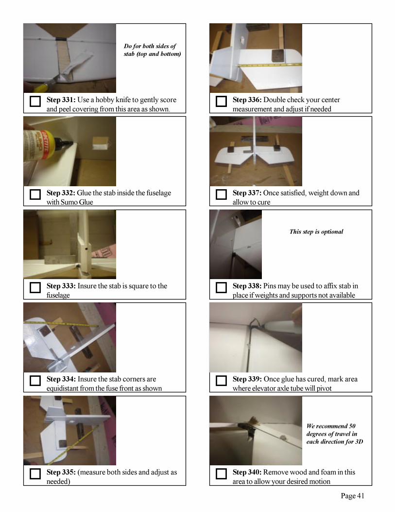
Step 335: (measure both sides and adjust asneeded)
Step 334: Insure the stab corners areequidistant from the fuse front as shown
Step 333: Insure the stab is square to thefuselage
Step 332: Glue the stab inside the fuselagewith Sumo Glue
Step 331: Use a hobby knife to gently scoreand peel covering from this area as shown.
Step 336: Double check your centermeasurement and adjust if needed
Step 337: Once satisfied, weight down andallow to cure
Step 338: Pins may be used to affix stab inplace if weights and supports not available
Step 340: Remove wood and foam in thisarea to allow your desired motion
Step 339: Once glue has cured, mark areawhere elevator axle tube will pivot
Do for both sides ofstab (top and bottom)
This step is optional
We recommend 50degrees of travel ineach direction for 3D

Page 42
Step 345: Iron more covering into the gaparea to help protect from fuel overspray
Step 344: Iron a small patch of covering tothe “front” area
Step 343: Trim balsa for a good fit into thefuselage as shown.
Step 342: Insert 5/16” balsa into the slot asshown and trace around fuselage
Step 341: Move elevators to insure there is nointerference and make clearance as needed.
Step 346: Glue the balsa piece in place asshown
Step 347: When glue has cured, sand/trimeven with fuselage sides.
Step 348: Apply covering to exposedwood.
Step 350: Install rudder and tape. Set asidefor glue to cure.
Step 349: Apply Gorilla Glue to rudderhinges
This step is optional
This step is optional Leave 1/16” gapbetween pieces andcenter the hinges in thegap as before

Page 43
Step 356: Free all clear plastic control hornsand sand off the small tabs at bottoms
Step 354: Pull the wires into the channel andout the other side.
Step 353: Tape the servo connectors to thewire (stagger connectors to minimize profile)
Step 352: Fish a thin wire into the channel tothe servo cavity as shown
Step 351: Gather parts and tools.
Step 357: Place horns over the full sizetemplate as shown
Step 358: Drill the holes where indicated tothe correct size hole for your clevises
Install Control Horns and Linkages
You’ll need :Rear Fuselage, Wings, Sumo Glueclear plastic control horns, push rodshobby knife, drafting square, plierselevator and rudder servos, servo arms24” long thin wire or similardrill matching clevis pin and push rod
diameters
Repeat for all horns
Step 360: Align elevator horn and bend tocorrect angle with pliers as shown.
Step 355: Drill holes for servo screws andinstall servos.
Step 359: Mark the elevator 1-14” from thefuselage side as shown
Be sure to use correcthorn! Elevator has asemi-circle missing atthe bottom corner tomate with the carbontube
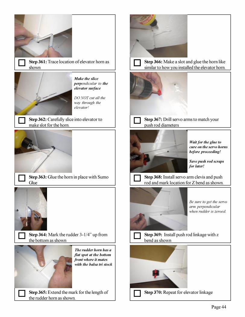
Page 44
Step 365: Extend the mark for the length ofthe rudder horn as shown.
Step 364: Mark the rudder 3-1/4” up fromthe bottom as shown
Step 363: Glue the horn in place with SumoGlue
Step 362: Carefully slice into elevator tomake slot for the horn.
Step 361: Trace location of elevator horn asshown
Step 366: Make a slot and glue the horn likesimilar to how you installed the elevator horn.
Step 368: Install servo arm clevis and pushrod and mark location for Z bend as shown.
Step 369: Install push rod linkage with zbend as shown
Step 370: Repeat for elevator linkage
Make the sliceperpendicular to theelevator surface
DO NOT cut all theway through theelevator!
The rudder horn has aflat spot at the bottomfront where it mateswith the balsa tri stock
Wait for the glue tocure on the servo hornsbefore proceeding!
Save push rod scrapsfor later!
Step 367: Drill servo arms to match yourpush rod diameters
Be sure to get the servoarm perpendicularwhen rudder is zeroed.
Page 45
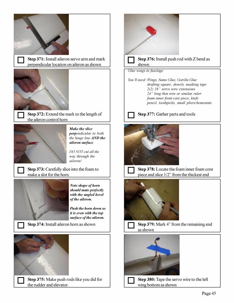
Step 375: Make push rods like you did forthe rudder and elevator.
Step 374: Install aileron horn as shown
Step 376: Install push rod with Z bend asshown.
Step 377: Gather parts and tools
Step 378: Locate the foam inner foam corepiece and slice 1/2” from the thickest end
Step 380: Tape the servo wire to the leftwing bottom as shown
Step 379: Mark 4” from the remaining endas shown
Step 373: Carefully slice into the foam tomake a slot for the horn.
Step 372: Extend the mark to the length ofthe aileron control horn
Make the sliceperpendicular to boththe hinge line AND theaileron surface
DO NOT cut all theway through theaileron!
Note shape of hornshould mate perfectlywith the angled bevelof the aileron.
Push the horn down soit is even with the topsurface of the aileron.
Step 371: Install aileron servo arm and markperpendicular location on aileron as shown
Glue wings to fuselage
You’ll need :Wings, Sumo Glue, Gorilla Gluedrafting square, dowels, masking tape2(2) 18” servo wire extensions24” long thin wire or similar, rulerfoam inner front core piece, knifepencil, toothpicks, small pliers/hemostats
Page 46
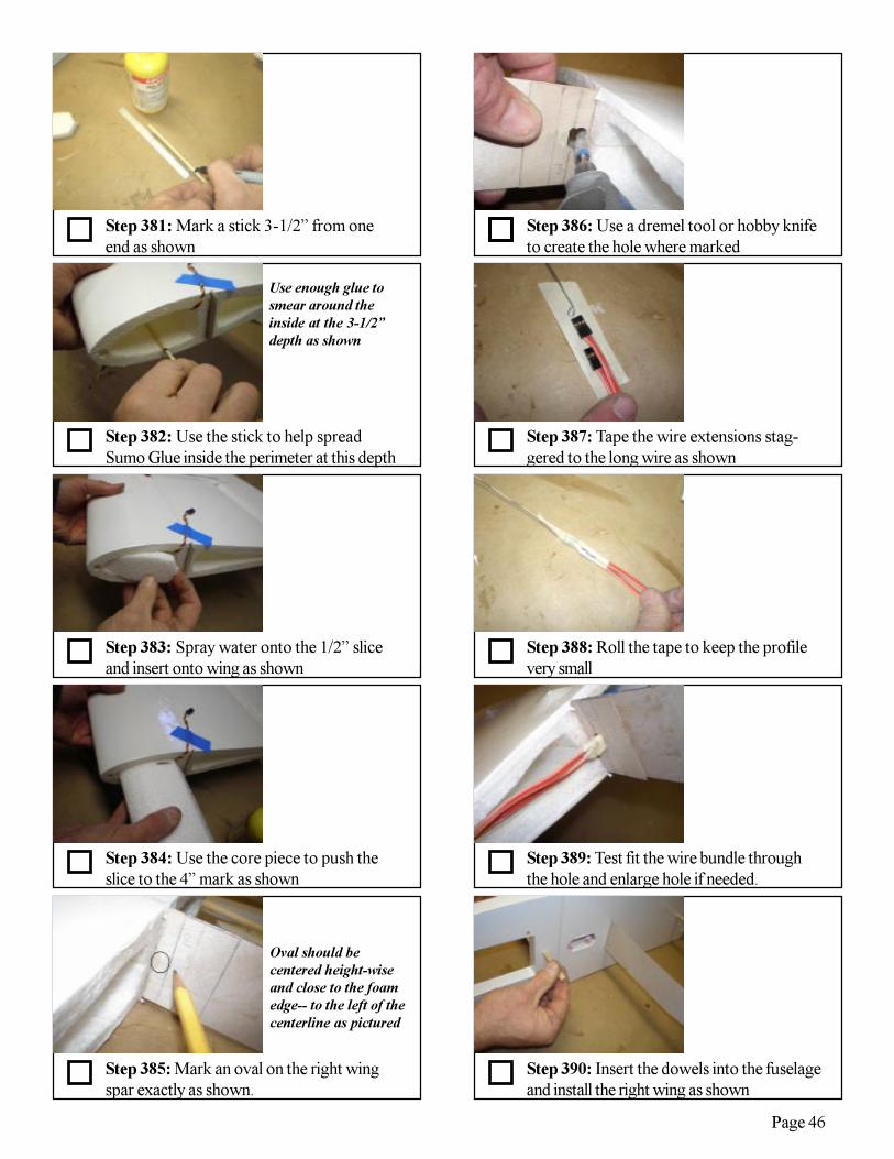
Step 385: Mark an oval on the right wingspar exactly as shown.
Step 384: Use the core piece to push theslice to the 4” mark as shown
Step 383: Spray water onto the 1/2” sliceand insert onto wing as shown
Step 382: Use the stick to help spreadSumo Glue inside the perimeter at this depth
Step 381: Mark a stick 3-1/2” from oneend as shown
Step 386: Use a dremel tool or hobby knifeto create the hole where marked
Step 387: Tape the wire extensions stag-gered to the long wire as shown
Step 388: Roll the tape to keep the profilevery small
Step 390: Insert the dowels into the fuselageand install the right wing as shown
Step 389: Test fit the wire bundle throughthe hole and enlarge hole if needed.
Use enough glue tosmear around theinside at the 3-1/2”depth as shown
Oval should becentered height-wiseand close to the foamedge-- to the left of thecenterline as pictured
Page 47
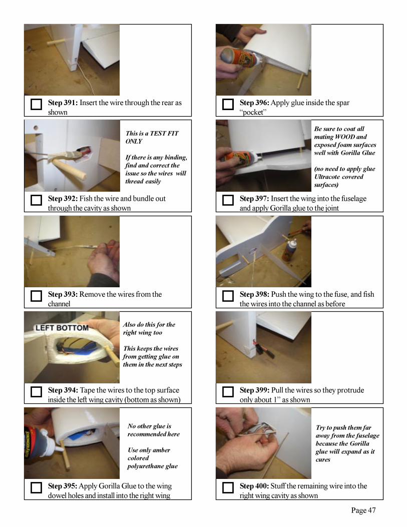
Step 395: Apply Gorilla Glue to the wingdowel holes and install into the right wing
Step 394: Tape the wires to the top surfaceinside the left wing cavity (bottom as shown)
Step 393: Remove the wires from thechannel
Step 392: Fish the wire and bundle outthrough the cavity as shown
Step 391: Insert the wire through the rear asshown
Step 396: Apply glue inside the spar“pocket”
Step 397: Insert the wing into the fuselageand apply Gorilla glue to the joint
Step 398: Push the wing to the fuse, and fishthe wires into the channel as before
Step 400: Stuff the remaining wire into theright wing cavity as shown
Step 399: Pull the wires so they protrudeonly about 1” as shown
This is a TEST FITONLY
If there is any binding,find and correct theissue so the wires willthread easily
Also do this for theright wing too
This keeps the wiresfrom getting glue onthem in the next steps
Be sure to coat allmating WOOD andexposed foam surfaceswell with Gorilla Glue
(no need to apply glueUltracote coveredsurfaces)
No other glue isrecommended here
Use only ambercoloredpolyurethane glue
Try to push them faraway from the fuselagebecause the Gorillaglue will expand as itcures
Page 48
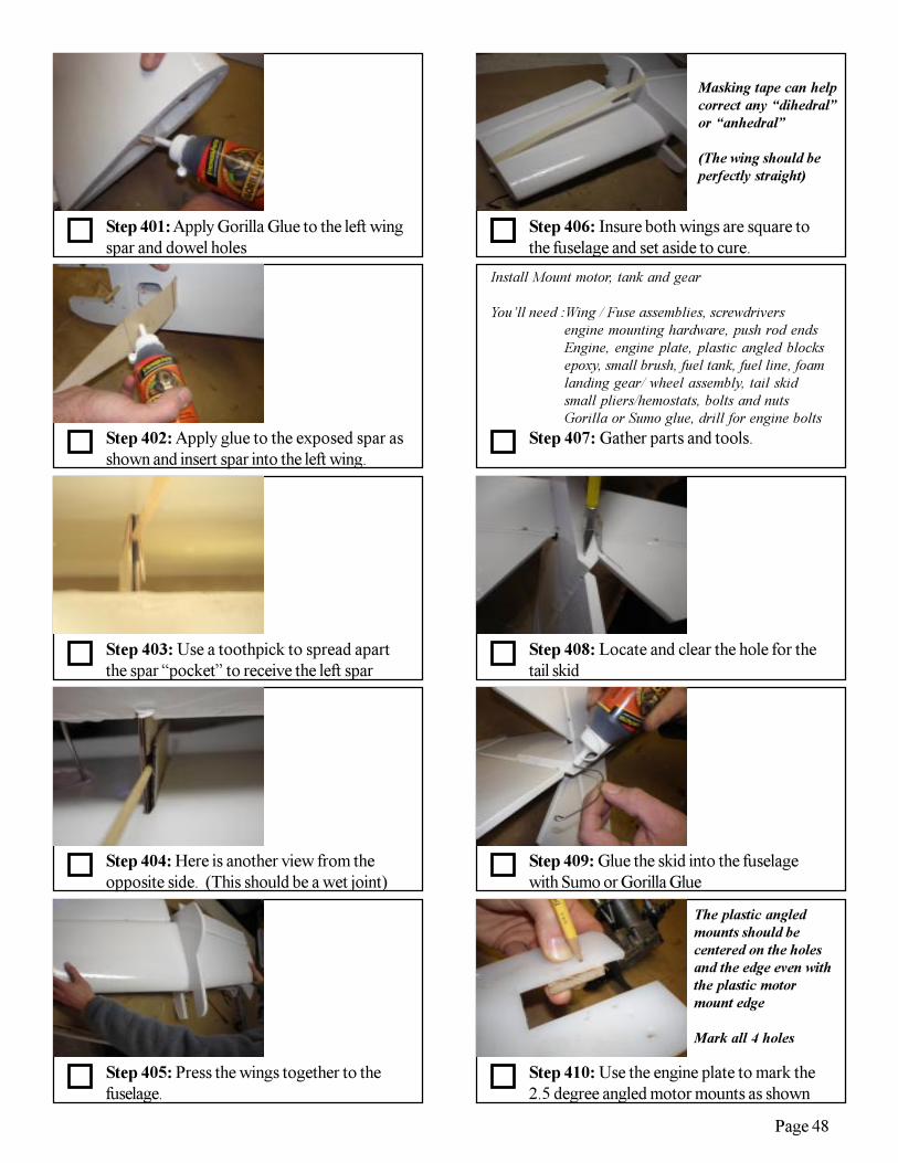
Step 405: Press the wings together to thefuselage.
Step 404: Here is another view from theopposite side. (This should be a wet joint)
Step 403: Use a toothpick to spread apartthe spar “pocket” to receive the left spar
Step 402: Apply glue to the exposed spar asshown and insert spar into the left wing.
Step 401: Apply Gorilla Glue to the left wingspar and dowel holes
Step 406: Insure both wings are square tothe fuselage and set aside to cure.
Step 407: Gather parts and tools.
Step 408: Locate and clear the hole for thetail skid
Step 410: Use the engine plate to mark the2.5 degree angled motor mounts as shown
Step 409: Glue the skid into the fuselagewith Sumo or Gorilla Glue
Masking tape can helpcorrect any “dihedral”or “anhedral”
(The wing should beperfectly straight)
Install Mount motor, tank and gear
You’ll need :Wing / Fuse assemblies, screwdriversengine mounting hardware, push rod endsEngine, engine plate, plastic angled blocksepoxy, small brush, fuel tank, fuel line, foamlanding gear/ wheel assembly, tail skidsmall pliers/hemostats, bolts and nutsGorilla or Sumo glue, drill for engine bolts
The plastic angledmounts should becentered on the holesand the edge even withthe plastic motormount edge
Mark all 4 holes
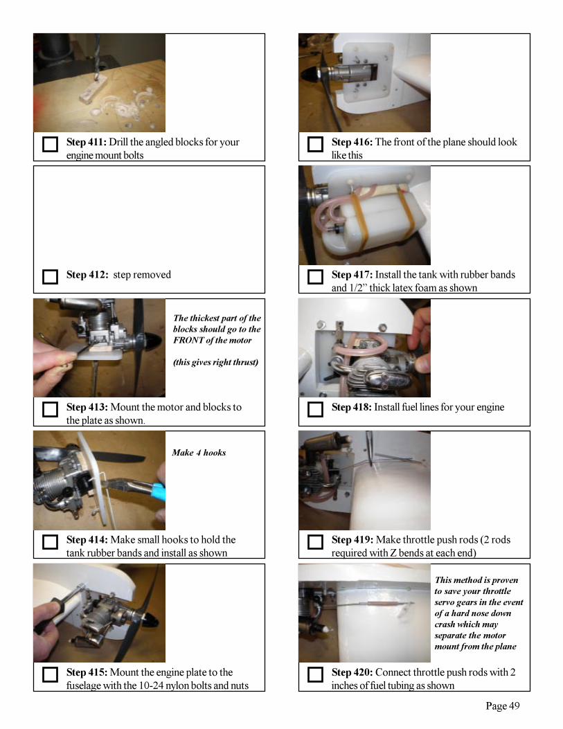
Page 49
Step 415: Mount the engine plate to thefuselage with the 10-24 nylon bolts and nuts
Step 414: Make small hooks to hold thetank rubber bands and install as shown
Step 413: Mount the motor and blocks tothe plate as shown.
Step 412: step removed
Step 411: Drill the angled blocks for yourengine mount bolts
Step 416: The front of the plane should looklike this
Step 417: Install the tank with rubber bandsand 1/2” thick latex foam as shown
Step 418: Install fuel lines for your engine
Step 420: Connect throttle push rods with 2inches of fuel tubing as shown
Step 419: Make throttle push rods (2 rodsrequired with Z bends at each end)
The thickest part of theblocks should go to theFRONT of the motor
(this gives right thrust)
Make 4 hooks
This method is provento save your throttleservo gears in the eventof a hard nose downcrash which mayseparate the motormount from the plane

Page 50
Step 425: Gather parts and tools
Step 424: Screw or just push the 6-32nylon bolts into the joiners.
Step 423: Shove the wires into the channelas you close the fuselage shut.
Step 422: Connect the servos wires.Hemostats are good to use here.
Step 421: Mount landing gear using 10-24nylon bolts and nuts.
Step 426: Measure and mark the hatchperimeter as shown
Step 427: Slice at an angle on the 3 perim-eter sides as shown
Step 428: Flip open the hatch and pull outthe wires
Step 429: Cut a small slit to hold the servoextension which acts like a battery switch
Four stroke oil linecan be affixed using awire tie clampedbetween the landinggear and fuselage asshown
suggested location ison wing top oppositethe hatch
(look ahead to seebattery lead which willplug inside for “on”)
Make Hatch and install radio
You’ll need :Hobby knife, ruler,radio receiver, battery, packing tape,6” servo extension or switch/charging jack“polyfill” foam or similar for radio packing
The boundary is 1”from the fuselage, 1”from the wing front, 1”from the spar and is 2-1/2” wide
Slice at an angle likeyou were cutting aHalloween pumpkintop
(so it won’t pushthrough when shut)
Step 430: Glue the servo extension so itprotrudes slightly from the wing top as shown
no nuts are needed!
Just press fit the screwsinto the joiner holesand they will stay!

Page 51
Step 435: Seal the hatch shut with packingtape. Iron any wrinkles afterward as needed.
Step 434: Pull the battery lead out and plugit into the battery to turn the plane “on”
Step 432: Connect and program your radio.(the extension goes to the RX battery slot)
Step 431: Make small slit for the batterylead to protrude from inside the hatch.
Step 436: We recommend 50 degrees eachway for the elevator. Adjust to your taste.
Step 438: We recommend 35 degrees ofaileron throw. Adjust to your taste.
Step 440: The recommended CG is 3/4”behind the spar. Enjoy!
Step 439: Insure up and down travel isequal for the ailerons.
The plans show a Saito .82 whichis the largest (and heaviest) enginerecommended
The engine may be mountedforward to balance the plane for atail heavy condition. If this isnecessary Drill new holes ahead ofthe previous ones in the whiteplastic motor mount and re-mountthe motor
Fly the plane and adjust the CGfor your taste.
Step 433: Wrap radio components in foam,and install under the hatch.
50% expo is highlyrecommended for 3Dthrows
50% expo is highlyrecommended for 3Dthrows

Page 52
Also look for these from TufFlight:The 4D-Lite:
Our first ELECTRIC powered kit. Indoor/outdoor super lightweight anddurable. Fly an entire 3D airshow in your front yard. One day build time. Fully3D capable deluxe kit versions available so you supply only your radio RX.
The Enduro 40:Unbelievably maneuverable and durable. Rugged landing gear and huge rudder/
side area allowing amazing knife edge maneuvers and spins.Introduced the "Rotolanding" to R/C - a flat spin to touchdown, with immediate
takeoff capability! (Enduro with snow skis shown at right)
4DOur most durable glo fuel .46 size 3D practice plane. Learn all 3D moves low to the
ground without fear of crashing. EPP wings and machined plastic fuselage, with durablecorplast full flying tail feathers. Not as precise as the Tuf Yak, but more crash forgiv-ing. Full flying stab and rudder. Undisputed tightest waterfalls ever!
The Panther:State of the art in Open B or Slow Survivable (SSC) combat. Unbelievably
maneuverable and durable. 60 inch span for great streamer catching and turning.
The Predator:Our first kit, and still a popular choice for sport or combat flying. New improved Version 6.0 very durable and
very aerobatic. Simplified construction with all new instructions (like this manual). Removable fin for easy storage,maintenance and transport. At 48” span and under 2.5 lbs, it’s a fast and agile “fly at a moment’s notice” plane.
Lost Model Alarm:A lightweight beeper triggered simply by turning off your transmitter. Since
it’s difficult to break our planes, the next challenge can be finding them in trees orbrush. This device helps a lot if a plane “flys away”.
Elevon Mixer (for flying wings):A simple lightweight programmable on-board electronic mixer. Allows sepa-
rate travel adjustment for elevator and aileron functions -- super important whenyou want to roll fast, but don’t want a real “touchy” elevator.
Warning: Combat is extremely fun andcontagious!
Many clubs around the country are discovering R/C combat.
See us online at: www.tufflight.com


