
Turbomachinery Sealing SolutionsSeals
SystemsServices
2
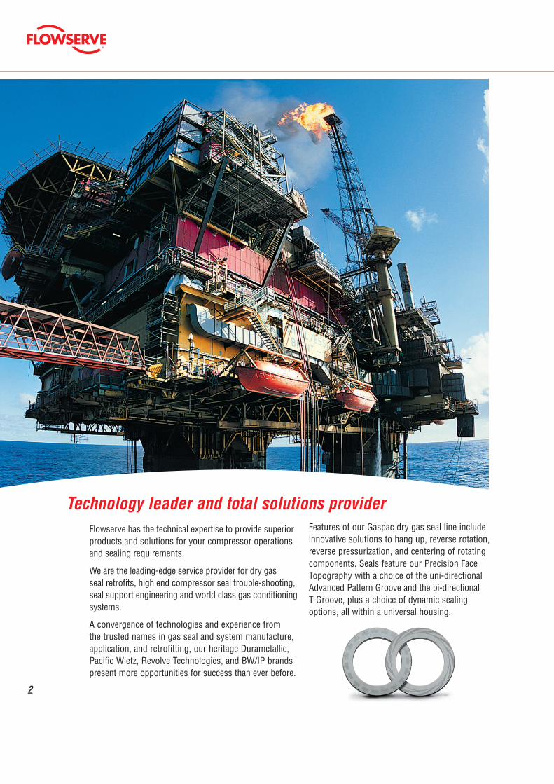
Flowserve has the technical expertise to provide superior products and solutions for your compressor operations and sealing requirements.
We are the leading-edge service provider for dry gas seal retrofits, high end compressor seal trouble-shooting, seal support engineering and world class gas conditioning systems.
A convergence of technologies and experience from the trusted names in gas seal and system manufacture, application, and retrofitting, our heritage Durametallic, Pacific Wietz, Revolve Technologies, and BW/IP brands present more opportunities for success than ever before.
Technology leader and total solutions provider Features of our Gaspac dry gas seal line include innovative solutions to hang up, reverse rotation, reverse pressurization, and centering of rotating components. Seals feature our Precision Face Topography with a choice of the uni-directional Advanced Pattern Groove and the bi-directional T-Groove, plus a choice of dynamic sealing options, all within a universal housing.
3
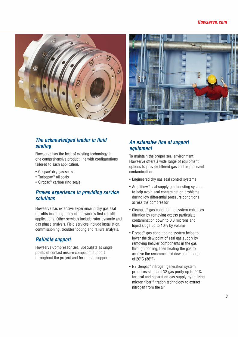
The acknowledged leader in fluid sealingFlowserve has the best of existing technology in one comprehensive product line with configurations tailored to each application.
• Gaspac® dry gas seals• TurbopacTM oil seals• CircpacTM carbon ring seals
Proven experience in providing service solutions
Flowserve has extensive experience in dry gas seal retrofits including many of the world’s first retrofit applications. Other services include rotor dynamic and gas phase analysis. Field services include installation, commissioning, troubleshooting and failure analysis.
Reliable supportFlowserve Compressor Seal Specialists as single points of contact ensure competent support throughout the project and for on-site support.
An extensive line of support equipmentTo maintain the proper seal environment, Flowserve offers a wide range of equipment options to provide filtered gas and help prevent contamination.
• Engineered dry gas seal control systems
• AmpliflowTM seal supply gas boosting system to help avoid seal contamination problems during low differential pressure conditions across the compressor
• CleanpacTM gas conditioning system enhances filtration by removing excess particulate contamination down to 0.3 microns and liquid slugs up to 10% by volume
• DrypacTM gas conditioning system helps to lower the dew point of seal gas supply by removing heavier components in the gas through cooling, then heating the gas to achieve the recommended dew point margin of 20°C (36°F)
• N2 GenpacTM nitrogen generation system produces standard N2 gas purity up to 99% for seal and separation gas supply by utilizing micron fiber filtration technology to extract nitrogen from the air

4
Flowserve Gaspac dry gas seals incorporate non contacting lift-off technology to provide low break away torque and reliable performance under all operating conditions.
The Gaspac is a standardized modular design in various configurations and sizes, following the Flowserve global technical standard.
Consistent qualityThis global standard ensures a harmonized technology with regard to:
• Dimensions and materials of the design
• Application range
• Manufacturing
• Interchangeability of seal parts
• Interchangeability of test fixtures
• Test conditions
• Test results and documentation
• Ease of serviceability
Gaspac Modular Design
We are the solutions provider for gas seal technology
Technology LeadershipFlowserve provides leading sealing technology solutions:
• High pressure services with 425 bar (6200 psi) dynamic and static pressure ratings to accommodate a wide range of rotating equipment applications
• Experienced in high speed solutions with tested peripheral velocity greater than 250 m/s (49,212 fpm) and speeds over 50,000 rpm
• Meeting customer reliability needs with more than 5 years mean time between repairs or overhaul
• Narrow and short axial designs for small seal chambers, ease of retrofit and reduced influence on rotordynamics
Around the world, thousands of Gaspac seals have been running millions of hours. The seal is a proven design using either the bi-directional T-Groove technology or the Advanced Pattern Groove (APG) technology. Both proven lift-off patterns have high film stiffness and damping capabilities that maintain the gas film under slow roll conditions as well as high speeds up to 250 m/s (49,212 fpm).
Leading-edge Precision Face Topography
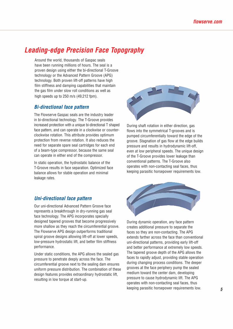
Bi-directional face pattern The Flowserve Gaspac seals are the industry leader in bi-directional technology. The T-Groove provides increased protection with a unique bi-directional T shaped face pattern, and can operate in a clockwise or counter-clockwise rotation. This attribute provides optimum protection from reverse rotation. It also reduces the need for separate spare seal cartridges for each end of a beam-type compressor, because the same seal can operate in either end of the compressor.
In static operation, the hydrostatic balance of the T-Groove results in face separation. Optimized face balance allows for stable operation and minimal leakage rates.
During shaft rotation in either direction, gas flows into the symmetrical T-grooves and is pumped circumferentially toward the edge of the groove. Stagnation of gas flow at the edge builds pressure and results in hydrodynamic lift-off, even at low peripheral speeds. The unique design of the T-Groove provides lower leakage than conventional patterns. The T-Groove also operates with non-contacting seal faces, thus keeping parasitic horsepower requirements low.
Uni-directional face pattern Our uni-directional Advanced Pattern Groove face represents a breakthrough in dry-running gas seal face technology. The APG incorporates specially designed tapered grooves that become progressively more shallow as they reach the circumferential groove. The Flowserve APG design outperforms traditional spiral groove designs allowing lift-off at lower speeds, low-pressure hydrostatic lift, and better film stiffness performance.
Under static conditions, the APG allows the sealed gas pressure to penetrate deeply across the face. The circumferential groove next to the sealing dam ensures uniform pressure distribution. The combination of these design features provides extraordinary hydrostatic lift, resulting in low torque at start-up.
During dynamic operation, any face pattern creates additional pressure to separate the faces so they are non-contacting. The APG extends farther across the face than conventional uni-directional patterns, providing early lift-off and better performance at extremely low speeds. The tapered groove depth of the APG allows the faces to rapidly adjust, providing stable operation during changing process conditions. The deeper grooves at the face periphery pump the sealed medium toward the center dam, developing pressure to cause hydrodynamic lift. The APG operates with non-contacting seal faces, thus keeping parasitic horsepower requirements low. 5

6
Spring energized O-ringOur LoDragTM dynamic secondary seal arrangement does not squeeze the O-ring in a fully confined groove, as in conventional gas seals. Instead, a 90 durometer dynamic O-ring is energized with the aid of a garter spring located on its outside diameter. While closing springs provide the O-ring axial compression between the stator and spring retainer, the garter spring provides adequate radial compression to effectively
seal the gas medium. Live loading of the dynamic O-ring provides constant sealing force while compensating for O-ring cross-section irregularities or swelling due to temperature or chemical reaction. The O-ring conforms to the sealing surface when inconsistencies exist on the surface or in the presence of dirt or deposits on the sealing surface. Drag and seal hang-up are greatly reduced.
The 90 durometer dynamic O-ring provides optimum properties for applications up to 120 bar (1740 psig), considering the explosive decompression and depressurization rates. Extended pressure applications can be adapted. The O-ring is designed to resist extrusion. Its high density minimizes the possibility of explosive decompression.
Additionally, because the O-ring is not confined radially, reverse pressure is easily handled. Back pressure is relieved by the O-ring and garter spring system, reducing the reverse pressure buildup that can cause other seals to fail.
PTFE J-ring sealThe PTFE dynamic seal, or J-ring seal, extends the operating range to temperatures of -100°C to 230°C (-148°F to 446°F) and pressures up to 425 bar (6164 psig). PTFE is also used for its extended chemical resistance beyond that of O-rings. The J-ring has a spring energized lip that functions similarly to the spring energized O-ring. The lip maintains contact with the sliding surface to provide a reliable seal. Pressure reversal is also handled effectively. The nonporous nature of PTFE has proven effective at minimizing explosive decompression. The combination of the Gaspac hard-versus-hard face configuration and J-ring design has allowed us to handle the highest pressures across a single seal face.
Innovative features in secondary seals

7
Gaspac standard features
Gaspac advanced features
Rotating face centeringIn both standard and advanced configurations, the rotating face is centered by a spring to ensure concentricity with the seal shaft sleeve. The spiral centering spring is designed to provide a centering force that always exceeds the eccentric force. The spring allows for even force distribution around the entire inner diameter of the rotating face, minimizing radial stresses in the rotating face.
Anti-rotation driveThe spiral springs used to center the rotating face are also designed to provide the anti- rotation torque needed to prevent the face from rotating under normal operation. The pins are provided as an added backup safety feature to provide additional resistance should excessive torque occur between the stationary and rotating faces. The combination provides extremely high torque capability without over stressing the materials.
O-rings for centering
Shrouded rotor
PTFE J-ring
Engineered centering strip
Shaft sleeve centeringThe shaft sleeve is centered utilizing O-rings as a standard where size and speed permit. The O-ring provides ease of installation and enhanced dampening characteristics. An en-gineered centering strip is used on seals that exceed the size and speed permitted for O-rings. The engineered centering strip is fully captured in a dovetail groove, ensuring positive retention during seal installation and removal. The center-ing strip is engineered to provide proper force to maintain concentricity without damaging the compressor shaft. The centering strip is available as an option on any seal.
Product features can be configured independently.
Spring centering device

8
Gaspac seal configurations
Gaspac SA single seal design is suitable for applications where the gas sealed, such as air, nitrogen, or carbon dioxide, is neither flammable nor harmful to the environment. Seal leakage is to the atmosphere. A Circpac or labyrinth seal may be integrated to reduce the amount of leakage in the event of a failure.
Gaspac DThe double opposed seal configuration requires a barrier gas pressure higher than the pressure of the process gas being sealed. This configuration can be used where any leakage of the process gas is not permissible, where consum ption of filtered buffer gas needs to be minimized, or in dirty gas applications or in low pressure applications where the flare pressure could exceed the sealing pressure.
-100°C to 230°C / -150°F to 450°F
1 to 250 m/s / 180 to 49,200 fpm
250 bar / 3,600 psiStandard Operating Limits
Pressure:
Temperature:
Speed:
Shaft size:40 mm to 360 mm / 1.500" to 14.125"
250 / 3600
-100 / -150 427 / 800
0 250 / 49200
360 / 14.1250 / 0
0 / 0
-100°C to 200°C / -150°F to 400°F
1 to 140 m/s / 180 to 27,600 fpm
60 bar / 870 psiStandard Operating Limits
Pressure:
Temperature:
Speed:
Shaft size:40 mm to 360 mm / 1.500" to 14.125"
0 / 0 250 / 3600
-100 / -150 427 / 800
0 250 / 49200
0 / 0 360 / 14.125
Pressure 0 / 0
Standard Operating Limits5800 psi / 400 bar
Temperature -148 / -100
-148ϒF to 446ϒF / -100
180 to 27000 fpm / 1 to 140 m/Speed 0 / 0
1.500" to 12.000" / 40 mm to 305 mmSizes 0 / 0

9
Gaspac TThe tandem seal provides full pressure breakdown across the primary seal faces. The secondary seal faces normally operate under low pressure. In the event of primary seal failure, the secondary seal acts as an installed spare. The process gas has controlled leakage across both sets of seal faces. The tandem seal has become an industry standard for hydrocarbon or critical applications.
Gaspac LThe tandem seal with interstage labyrinth is used to eliminate process gas leakage to the atmosphere. This is accomplished by introduction of an inert buffer gas to the secondary seal. With a slightly higher inert buffer gas pressure, the labyrinth will keep the process gas from migrating to the secondary seal faces. The interstage labyrinth provides a low pressure solution to controlling emissions across a gas seal.
-100°C to 230°C / -150°F to 450°F
1 to 250 m/s / 180 to 49,200 fpm
650 bar / 9,427 psiStandard Operating Limits
Pressure:
Temperature:
Speed:
Shaft size:40 mm to 360 mm / 1.500" to 14.125"
650 / 9427
-100 / -150 427 / 800
0 250 / 49200
360 / 14.1250 / 0
0 / 0
-100°C to 230°C / -150°F to 450°F
1 to 250 m/s / 180 to 49,200 fpm
650 bar / 9,427 psiStandard Operating Limits
Pressure:
Temperature:
Speed:
Shaft size:40 mm to 360 mm / 1.500" to 14.125"
650 / 9427
-100 / -150 427 / 800
0 250 / 49200
360 / 14.1250 / 0
0 / 0
The Gaspac L can be configured to handle extremely high pressures, up to 650 bar (9,427 psig).

A ductile rotor/sleeve dry gas seal that features fewer parts and secondary seals. The ductile rotor eliminates the chance of brittle face failure. This seal was designed for either retrofit or new centrifugal gas compressor applications in gas production and transmission, air separation, chemical refining and petrochemical industries.
The Gaspac Integrated Rotor seal is used successfully in natural gas transmission and high speed turbo-expander applications specifically to eliminate brittle face failure.
Screw compressors and turbo-expanders often have extremely small seal cavities in which standard dry gas seals may not fit. The Gaspac Integrated Rotor seals combine the rotating face and sleeve into one part, decreasing the amount of axial space required for a dry gas seal.
Gaspac Integrated Rotor dry gas seal
Gaspac S-IR
Gaspac D-IR
This not only eliminates the use of an extra, ceramic rotating face, but also makes it possible to trade spaces with short, thin cross-sectioned labyrinths. Gaspac Integrated Rotor designs are available as single or double seals.
10
Standard Operating Limits
Pressure:
Temperature:
Speed:
Shaft size:
-40 / -40
0
80°C / 180°F
140 m/s / 27,600 fpm
5 bar / 70 psi
40 mm to 360 mm / 1.500" to 14.125"
0 / 0
0 / 0 69 / 1000
427 / 800
140 / 27600
360 / 14.125
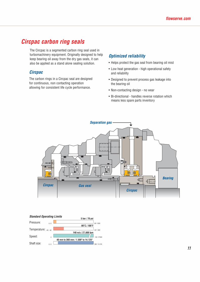
The Circpac is a segmented carbon ring seal used in turbomachinery equipment. Originally designed to help keep bearing oil away from the dry gas seals, it can also be applied as a stand alone sealing solution.
Circpac carbon ring seals
Circpac The carbon rings in a Circpac seal are designed for continuous, non contacting operation allowing for consistent life cycle performance.
Gas sealCircpac
Bearing
Separation gas
Circpac
Optimized reliability • Helps protect the gas seal from bearing oil mist
• Low heat generation - high operational safety and reliability
• Designed to prevent process gas leakage into the bearing oil
• Non-contacting design - no wear
• Bi-directional - handles reverse rotation which means less spare parts inventory
11
Main page header here
Standard Operating Limits
Pressure:
Temperature:
Speed:
Shaft size:
-100 / -150
0
0 / 0
0 / 0
80°C / 180°F
140 m/s / 27,600 fpm
5 bar / 70 psi
40 mm to 360 mm / 1.500" to 14.125"
69 / 1000
427 / 800
140 / 27600
360 / 14.125
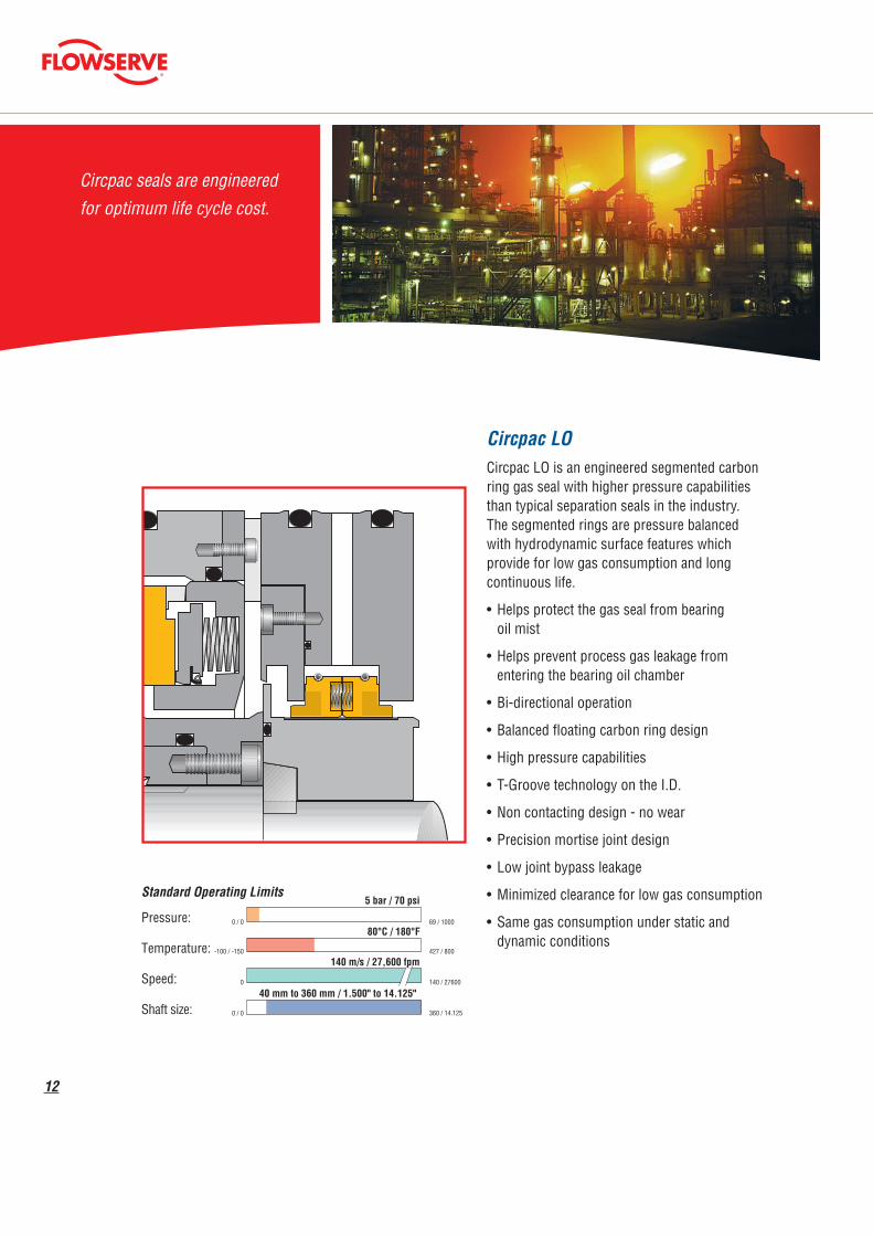
Circpac LO Circpac LO is an engineered segmented carbon ring gas seal with higher pressure capabilities than typical separation seals in the industry. The segmented rings are pressure balanced with hydrodynamic surface features which provide for low gas consumption and long continuous life.
• Helps protect the gas seal from bearing oil mist
• Helps prevent process gas leakage from entering the bearing oil chamber
• Bi-directional operation
• Balanced floating carbon ring design
• High pressure capabilities
• T-Groove technology on the I.D.
• Non contacting design - no wear
• Precision mortise joint design
• Low joint bypass leakage
• Minimized clearance for low gas consumption
• Same gas consumption under static and dynamic conditions
12
Circpac seals are engineered for optimum life cycle cost.

Circpac HP for stand alone operationA Circpac can also be used as a cost effective stand-alone carbon ring seal. A multiple carbon ring config-uration can be utilized in low pressure applications where the very low leakage of a conventional gas seal is not required.
Circpac HP ring configurationsAny ring combination can be arranged in a Circpac seal to meet specific application requirements. Additional features such as labyrinths, face seals, pressure sensing ports and purge/vent/drain ports are available.
Single Tandem Double
Double with purge and vent
Dual double with vent
Standard Operating Limits
Pressure:
Temperature:
Speed:
Shaft size:
0 / 0
-40 / -40
0
0 / 0
180°C / 350°F
90 m/s / 18,000 fpm
10 bar / 150 psi
25 mm to 280 mm / 1.000" to 11.000"
69 / 1000
427 / 800
140 / 27600
360 / 14.125 13
14
Turbopac compressor sealsFlowserve offers Turbopac oil lubricated mechanical seals arranged in the following configurations:
• product side, single mechanical seal combined with an atmospheric floating ring or labyrinth seal
• double mechanical seals in face to face arrangements
The gaps of the floating ring seal or labyrinth are designed to have the barrier and cooling fluid continu-ously diverted to the bearing side. The gap is increased allowing additional flow through the seal for higher surface speed machines in order to dissipate the heat generated by the resulting increased friction. In some cases a portion of the flow is even diverted back to the oil tank prior to the floating ring seal in order to provide sufficient cooling.
High operational safety, low cost sealing solutions
Since 1968, more than 10,000 Turbopac compressor seals have been delivered worldwide. Dependability and performance like this are due in part to the following features:
• a stationary spring assembly allows higher rotational speeds
• higher safety, efficiency and reduced oil loss from the low leakage rate
• the robust design provides long life and lower life cycle cost
• dual acting static seal allowing for product containment under reverse pressure conditions
• available in a cartridge design for simpler installation
• designed to handle emergency shut downs for added safety
For over thirty years, the sealing solutions for compressors
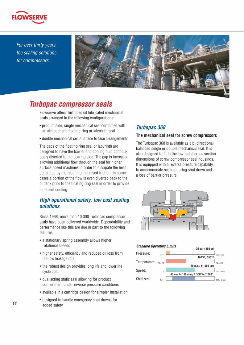
Turbopac 368The mechanical seal for screw compressors
The Turbopac 368 is available as a bi-directional balanced single or double mechanical seal. It is also designed to fit in the low radial cross section dimensions of screw compressor seal housings. It is equipped with a reverse pressure capability, to accommodate sealing during shut down and a loss of barrier pressure.
Standard Operating Limits
Pressure:
Temperature:
Speed:
Shaft size:
0 / 0
-40 / -40
0
0 / 0
180°C / 350°F
60 m/s / 11,900 fpm
25 bar / 350 psi
40 mm to 180 mm / 1.500" to 7.000"
300 / 4300
427 / 800
100 / 19500
305 / 12.000
productside
bearingside
oilflow oil
flow
15
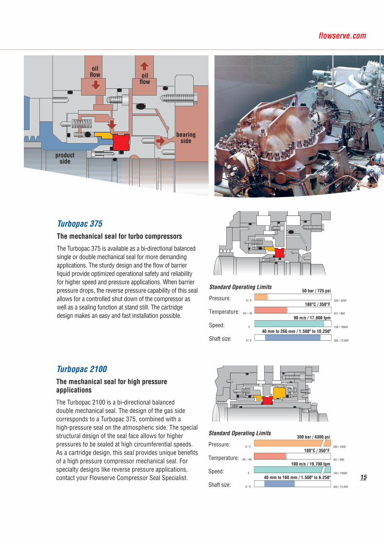
Turbopac 375The mechanical seal for turbo compressors
The Turbopac 375 is available as a bi-directional balanced single or double mechanical seal for more demanding applications. The sturdy design and the flow of barrier liquid provide optimized operational safety and reliability for higher speed and pressure applications. When barrier pressure drops, the reverse pressure capability of this seal allows for a controlled shut down of the compressor as well as a sealing function at stand still. The cartridge design makes an easy and fast installation possible.
Turbopac 2100The mechanical seal for high pressure applications
The Turbopac 2100 is a bi-directional balanced double mechanical seal. The design of the gas side corresponds to a Turbopac 375, combined with a high-pressure seal on the atmospheric side. The special structural design of the seal face allows for higher pressures to be sealed at high circumferential speeds. As a cartridge design, this seal provides unique benefits of a high pressure compressor mechanical seal. For specialty designs like reverse pressure applications, contact your Flowserve Compressor Seal Specialist.
Standard Operating Limits
Pressure:
Temperature:
Speed:
Shaft size:
0 / 0
-40 / -40
0
0 / 0
180°C / 350°F
90 m/s / 17,800 fpm
50 bar / 725 psi
40 mm to 260 mm / 1.500" to 10.250"
300 / 4300
427 / 800
100 / 19500
305 / 12.000
Standard Operating Limits
Pressure:
Temperature:
Speed:
Shaft size:
0 / 0
-40 / -40
0
0 / 0
180°C / 350°F
100 m/s / 19,700 fpm
300 bar / 4300 psi
40 mm to 160 mm / 1.500" to 6.250"
300 / 4300
427 / 800
100 / 19500
305 / 12.000
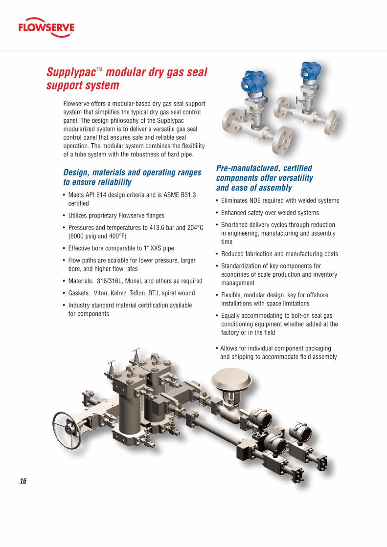
Flowserve offers a modular-based dry gas seal support system that simplifies the typical dry gas seal control panel. The design philosophy of the Supplypac modularized system is to deliver a versatile gas seal control panel that ensures safe and reliable seal operation. The modular system combines the flexibility of a tube system with the robustness of hard pipe.
Pre-manufactured, certified components offer versatility and ease of assembly • Eliminates NDE required with welded systems
• Enhanced safety over welded systems
• Shortened delivery cycles through reduction in engineering, manufacturing and assembly time
• Reduced fabrication and manufacturing costs
• Standardization of key components for economies of scale production and inventory management
• Flexible, modular design, key for offshore installations with space limitations
• Equally accommodating to bolt-on seal gas conditioning equipment whether added at the factory or in the field
• Allows for individual component packaging and shipping to accommodate field assembly
Design, materials and operating ranges to ensure reliability• Meets API 614 design criteria and is ASME B31.3 certified
• Utilizes proprietary Flowserve flanges
• Pressures and temperatures to 413.6 bar and 204°C (6000 psig and 400°F)
• Effective bore comparable to 1" XXS pipe
• Flow paths are scalable for lower pressure, larger bore, and higher flow rates
• Materials: 316/316L, Monel, and others as required
• Gaskets: Viton, Kalrez, Teflon, RTJ, spiral wound
• Industry standard material certification available for components
16
Supplypac TM modular dry gas seal support system
17
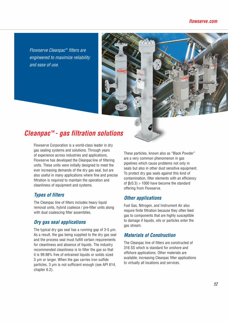
Cleanpac TM - gas filtration solutionsFlowserve Corporation is a world-class leader in dry gas sealing systems and solutions. Through years of experience across industries and applications, Flowserve has developed the Cleanpac line of filtering units. These units were initially designed to meet the ever increasing demands of the dry gas seal, but are also useful in many applications where fine and precise filtration is required to maintain the operation and cleanliness of equipment and systems.
Types of filtersThe Cleanpac line of filters includes heavy liquid removal units, hybrid coalesce / pre-filter units along with dual coalescing filter assemblies.
Dry gas seal applicationsThe typical dry gas seal has a running gap of 3-5 µm. As a result, the gas being supplied to the dry gas seal and the process seal must fulfill certain requirements for cleanliness and absence of liquids. The industry recommended cleanliness is to filter the gas so that it is 99.98% free of entrained liquids or solids sized 3 µm or larger. When the gas carries iron sulfide particles, 3 µm is not sufficient enough (see API 614, chapter 6.2).
These particles, known also as “Black Powder” are a very common phenomenon in gas pipelines which cause problems not only in seals but also in other dust sensitive equipment. To protect dry gas seals against this kind of contamination, filter elements with an efficiency of β(0.3) > 1000 have become the standard offering from Flowserve.
Other applicationsFuel Gas, Nitrogen, and Instrument Air also require finite filtration because they often feed gas to components that are highly susceptible to damage if liquids, oils or particles enter the gas stream.
Materials of ConstructionThe Cleanpac line of filters are constructed of 316 SS which is standard for onshore and offshore applications. Other materials are available, increasing Cleanpac filter applications to virtually all locations and services.
Flowserve CleanpacTM filters are engineered to maximize reliability and ease of use.
18
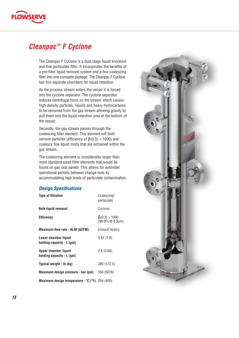
CleanpacTM F Cyclone
Design Specifications
The Cleanpac F Cyclone is a dual stage liquid knockout and fine particulate filter. It incorporates the benefits of a pre-filter liquid removal system and a fine coalescing filter into one complete package. The Cleanpac F Cyclone has two separate chambers for liquid retention.
As the process stream enters the vessel it is forced into the cyclone separator. The cyclone separator induces centrifugal force on the stream which causes high density particles, liquids and heavy hydrocarbons to be removed from the gas stream allowing gravity to pull them into the liquid retention area at the bottom of the vessel.
Secondly, the gas stream passes through the coalescing filter element. This element will both remove particles (efficiency of β(0.3) > 1000) and coalesce fine liquid mists that are entrained within the gas stream.
The coalescing element is considerably larger than most standard sized filter elements that would be found on gas seal panels. This allows for extended operational periods between change-outs by accommodating high levels of particulate contamination.
Type of filtration Coalescing/ particulate
Bulk liquid removal Cyclone
Efficiency β(0.3) > 1000 (99.9% @ 0.3µm)
Maximum flow rate - ALM (ACFM) Consult factory
Lower chamber liquid 3.87 (1.0) holding capacity - L (gal)
Upper chamber liquid 2.6 (0.68) holding capacity - L (gal)
Typical weight - lb (kg) 380 (172.3)
Maximum design pressure - bar (psi) 350 (5076)
Maximum design temperature - °C (°F) 204 (400)
19
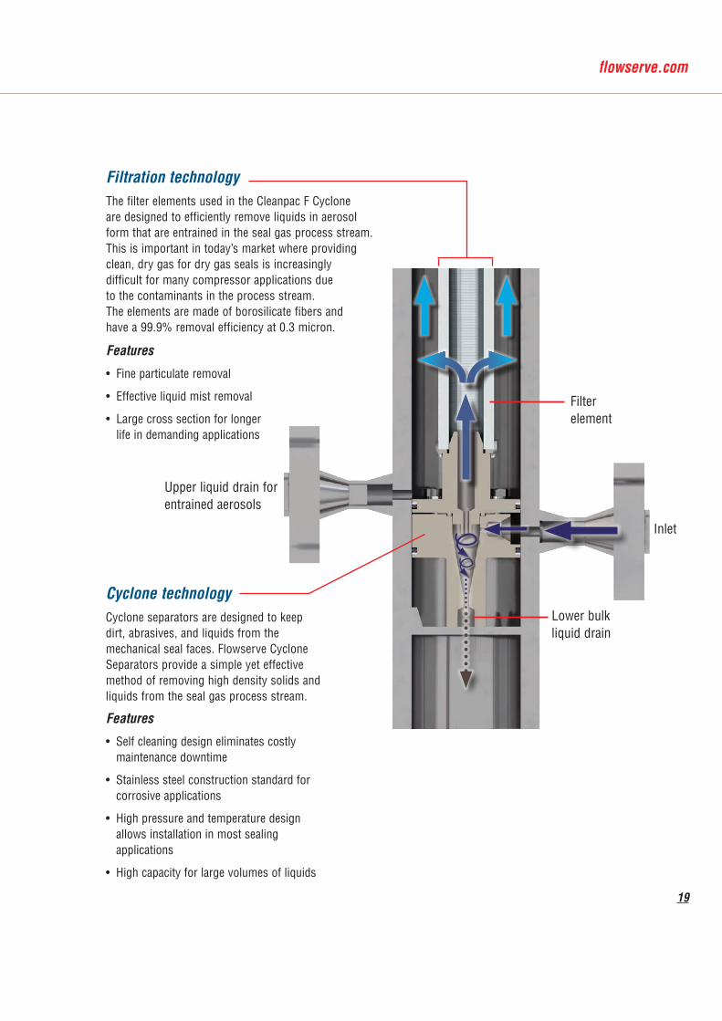
Cyclone technologyCyclone separators are designed to keep dirt, abrasives, and liquids from the mechanical seal faces. Flowserve Cyclone Separators provide a simple yet effective method of removing high density solids and liquids from the seal gas process stream.
Features
• Self cleaning design eliminates costly maintenance downtime
• Stainless steel construction standard for corrosive applications
• High pressure and temperature design allows installation in most sealing applications
• High capacity for large volumes of liquids
Filter element
Inlet
Lower bulk liquid drain
Upper liquid drain for entrained aerosols
Filtration technologyThe filter elements used in the Cleanpac F Cyclone are designed to efficiently remove liquids in aerosol form that are entrained in the seal gas process stream. This is important in today’s market where providing clean, dry gas for dry gas seals is increasingly difficult for many compressor applications due to the contaminants in the process stream. The elements are made of borosilicate fibers and have a 99.9% removal efficiency at 0.3 micron.
Features
• Fine particulate removal
• Effective liquid mist removal
• Large cross section for longer life in demanding applications

20
The Cleanpac DC liquid removal pre-filters incorporate dual stage technology to ensure maximum efficiency.
As the gas stream enters the pre-filter it encounters a deflector plate that disrupts the flow and causes turbulence. The turbulence allows removal of liquids and heavy hydrocarbons from the gas stream and these drop via gravity into the liquid retention area at the bottom of the vessel.
Secondly, the gas stream passes through the stainless steel mesh pad. This mesh pad removes large particles (>20 µm) and coalesces fine mists and liquids that are entrained within the gas stream.
The technology within the Cleanpac DC has been installed in many and various applications around the world with a very high success rate.
CleanpacTM DC pre-filter
Design SpecificationsType of filtration Bulk liquid removal
Efficiency β(20) > 100 (99% @ 20 µm)
Maximum flow rate - ALM (ACFM) Consult factory
Lower chamber liquid 0.75 (0.2) holding capacity - L (gal)
Typical Weight - lb (kg) 76 (34.5)
Maximum design pressure - bar (psi) 350 (5076)
Maximum design temperature - °C (°F) 204 (400)

21
CleanpacTM DL dual and single assemblies
The Cleanpac DL is a general service coalescing filter assembly designed to protect dry gas seals and other sensitive equipment from particles and fine liquid mists. The simple design is focused on the safety of continuous flow and ease of use.
Design Specifications
The basic Cleanpac DL is comprised of a single 316 stainless steel housing, incorporating a 0.3 µm stainless steel coalescing filter element. This housing can be configured in single or dual arrangements (with or without transfer valve) and in a double block
and bleed arrangement.
With the addition of actuated transfer valves, the versatility of the Cleanpac DL is expanded to include utilization in unmanned stations.
Type of filtration Coalescing
Bulk liquid removal na
Efficiency β(0.3) > 1000 (99.9% @ 0.3µm)
Maximum flow rate - ALM (ACFM) Consult factory
Lower chamber liquid 0.213 (0.05) holding capacity - L (gal)
Weight - lb (kg) 250 (113.3) (dual assembly)
Maximum design pressure - bar (psi) 250 (3626)
Maximum design temperature - °C (°F) 150 (302)
22
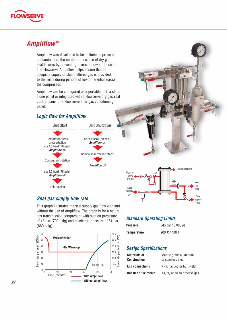
Ampliflow was developed to help eliminate process contamination, the number one cause of dry gas seal failures by preventing reversed flow in the seal. The Flowserve Ampliflow helps ensure that an adequate supply of clean, filtered gas is provided to the seals during periods of low differential across the compressor.
Ampliflow can be configured as a portable unit, a stand alone panel or integrated with a Flowserve dry gas seal control panel or a Flowserve filter gas conditioning panel.
Ampliflow TM
Seal gas supply flow rateThis graph illustrates the seal supply gas flow with and without the use of Ampliflow. The graph is for a natural gas transmission compressor with suction presssure of 48 bar (700 psig) and discharge pressure of 61 bar (880 psig).
Design SpecificationsMaterials of Marine grade aluminum Construction or stainless steel
End connections NPT, flanged or butt weld
Booster drive media Air, N2 or clean process gas
Logic flow for Ampliflow
Unit Start
Compressor case pressurization
dp<4.8 bard (70 psid)Ampliflow on
Compressor rotation
dp>5.2 bard (75 psid)Ampliflow off
Unit running
Unit Shutdown
dp<4.8 bard (70 psid)Ampliflow on
Compressor rotation stops
PI
PS
To atmosphere
Sealsupply
gas
Ventto
flare
Boosterdrive media
Sealsupply
gas
Flow
rate
per
sea
l (SC
FM)
Pressurization
Idle Warm-up
Ramp-up Flow
rate
per
sea
l (NL
PM)
Standard Operating LimitsPressure 345 bar / 5,000 psi
Temperature 200°C / 400°F
Time (minutes) With AmpliflowWithout Ampliflow
Ampliflow off
120
100
80
60
40
20
00 10 20 30 40 50
57.0
47.5
38.0
28.5
19.0
9.5

DrypacTM
Drypac will reduce the potential of liquid formation between the seal faces by lowering the dew point of the gas and raising the temperature of the seal supply gas at least 20°C (36°F) above the dew point as recommended by API standards.
CleanpacTM
Cooling
Drypac advantage • Helps increase the MTBF of dry gas seals when the dew point of the gas is a potential issue
• Simplified installation, operation and maintenance
• Can be integrated with an existing gas seal control panel
Heater
Ampliflow
Cleanpac
TE
To flare
Process gas
M
TC
PDIT
To flare
Cooling element
Heating element
Process gasFiltration
To compressor
suction separator
To flare
S
23
Heating
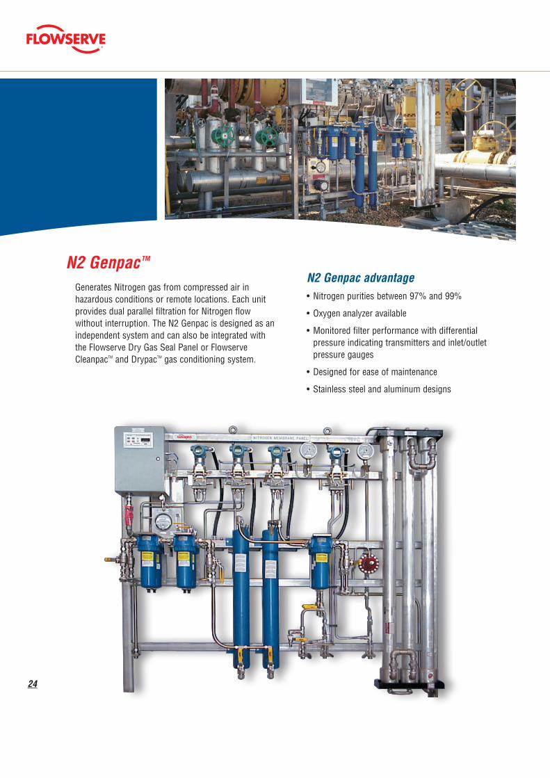
N2 Genpac advantage • Nitrogen purities between 97% and 99%
• Oxygen analyzer available
• Monitored filter performance with differential pressure indicating transmitters and inlet/outlet pressure gauges
• Designed for ease of maintenance
• Stainless steel and aluminum designs
24
N2 Genpac TM
Generates Nitrogen gas from compressed air in hazardous conditions or remote locations. Each unit provides dual parallel filtration for Nitrogen flow without interruption. The N2 Genpac is designed as an independent system and can also be integrated with the Flowserve Dry Gas Seal Panel or Flowserve CleanpacTM and DrypacTM gas conditioning system.
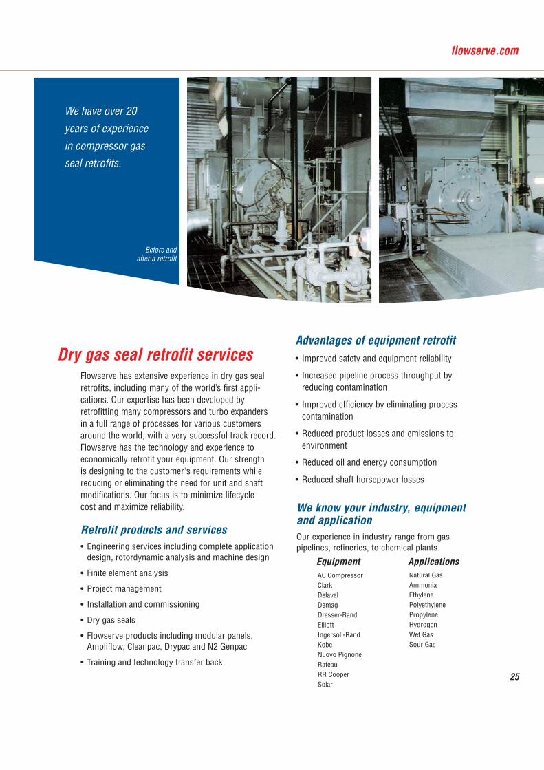
We have over 20 years of experience in compressor gas seal retrofits.
Equipment Applications
Retrofit products and services• Engineering services including complete application design, rotordynamic analysis and machine design
• Finite element analysis
• Project management
• Installation and commissioning
• Dry gas seals
• Flowserve products including modular panels, Ampliflow, Cleanpac, Drypac and N2 Genpac
• Training and technology transfer back
AC CompressorClarkDelavalDemagDresser-RandElliottIngersoll-RandKobeNuovo PignoneRateauRR CooperSolar
We know your industry, equipment and applicationOur experience in industry range from gas pipelines, refineries, to chemical plants.
Natural GasAmmoniaEthylene PolyethylenePropyleneHydrogenWet GasSour Gas
25
Dry gas seal retrofit servicesFlowserve has extensive experience in dry gas seal retrofits, including many of the world’s first appli-cations. Our expertise has been developed by retrofitting many compressors and turbo expanders in a full range of processes for various customers around the world, with a very successful track record. Flowserve has the technology and experience to economically retrofit your equipment. Our strength is designing to the customer's requirements while reducing or eliminating the need for unit and shaft modifications. Our focus is to minimize lifecycle cost and maximize reliability.
Advantages of equipment retrofit• Improved safety and equipment reliability
• Increased pipeline process throughput by reducing contamination
• Improved efficiency by eliminating process contamination
• Reduced product losses and emissions to environment
• Reduced oil and energy consumption
• Reduced shaft horsepower losses
Before and after a retrofit
Compressor service solutionsWith today's increasingly complex operations, you need someone with the knowledge, experience and training to help maximize your equipment efficiency and reliability. You can rely on the competency of the Flowserve Compressor Seal Specialist.
The Flowserve Compressor Seal SpecialistsThese highly trained individuals are the ones you can rely on to provide solutions. They have the knowledge and skills to handle field repairs, troubleshooting and service. They know your equipment inside out and are the ones you can depend on for everything from hands on training to equipment retrofits.
The Flowserve Compressor Seal Specialists are your single points of contact for project management, installation, commissioning, troubleshooting and training.
26
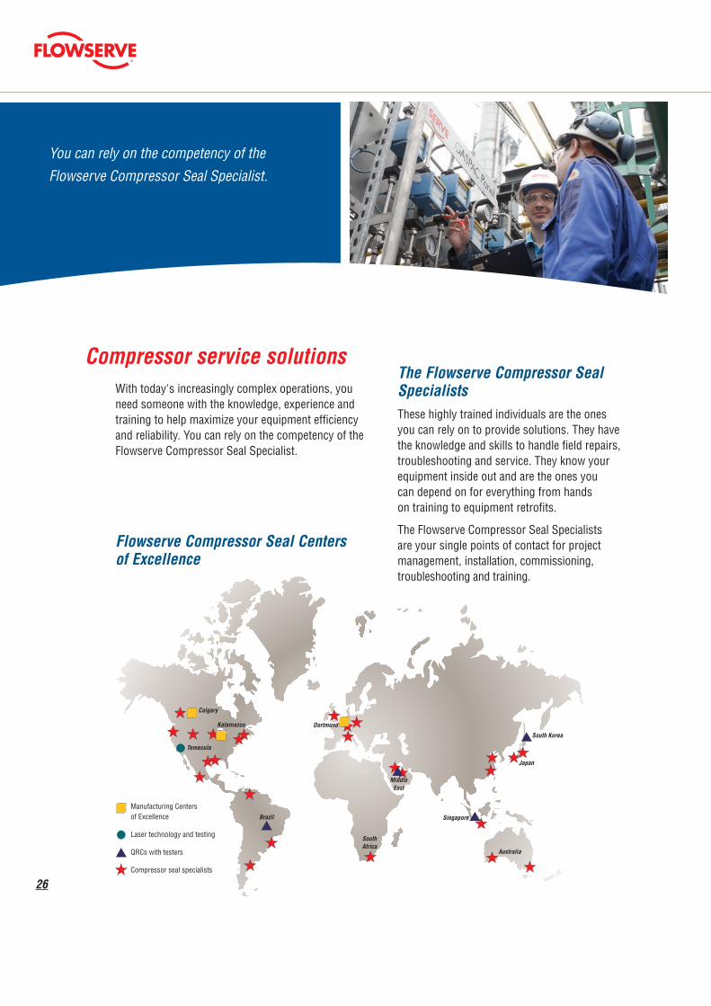
Flowserve Compressor Seal Centers of Excellence
You can rely on the competency of the Flowserve Compressor Seal Specialist.
Manufacturing Centers of Excellence
Laser technology and testing
QRCs with testers
Compressor seal specialists
Calgary
Kalamazoo
Temecula
Brazil
SouthAfrica
MiddleEast
Dortmund
Singapore
Australia
Japan
South Korea
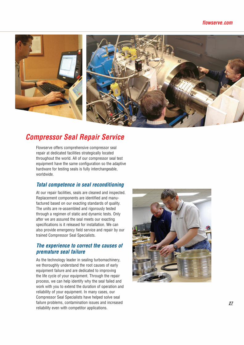
Flowserve offers comprehensive compressor seal repair at dedicated facilities strategically located throughout the world. All of our compressor seal test equipment have the same configuration so the adaptive hardware for testing seals is fully interchangeable, worldwide.
Total competence in seal reconditioningAt our repair facilities, seals are cleaned and inspected. Replacement components are identified and manu-factured based on our exacting standards of quality. The units are re-assembled and rigorously tested through a regimen of static and dynamic tests. Only after we are assured the seal meets our exacting specifications is it released for installation. We can also provide emergency field service and repair by our trained Compressor Seal Specialists.
The experience to correct the causes of premature seal failureAs the technology leader in sealing turbomachinery, we thoroughly understand the root causes of early equipment failure and are dedicated to improving the life cycle of your equipment. Through the repair process, we can help identify why the seal failed and work with you to extend the duration of operation and reliability of your equipment. In many cases, our Compressor Seal Specialists have helped solve seal failure problems, contamination issues and increased reliability even with competitor applications.
Compressor Seal Repair Service
27

FCD LMABR1400-00 Printed in USA. (Replaces 140-10000)FSD113eng A4 REV 07-15 Printed in USA.
Germany Flaspoete 101, D-44388Dortmund, GermanyTelephone: 49 231 6964 0Telefax: 49 231 6964 248
United States2100 Factory StreetKalamazoo, MI 49001 USATelephone: 269 381 2650Telefax: 269 226 3404
CanadaSuite 152221 41st Avenue. NECalgary, Alberta T2E 6P2 CanadaTelephone: 403 212 3811Telefax: 403 212 3846
To find your local Flowserve representativeand find out more about Flowserve Corporation,visit www.flowserve.com
© 2015 Flowserve Corporation
Flowserve Corporation has established industry leadership in the design and manufacture of its products. When properly selected, this Flowserve product is designed to perform its intended function safely during its useful life. However, the purchaser or user of Flowserve products should be aware that Flowserve products might be used in numerous applications under a wide variety of industrial service conditions. Although Flowserve can provide general guidelines, it cannot provide specific data and warnings for all possible applications. The purchaser/user must therefore assume the ultimate responsibility for the proper sizing and selection, installation, operation, and maintenance of Flowserve products. The purchaser/user should read and understand the Installation Instructions included with the product, and train its employees and contractors in the safe use of Flowserve products in connection with the specific application.
While the information and specifications contained in this literature are believed to be accurate, they are supplied for informative purposes only and should not be considered certified or as a guarantee of satisfactory results by reliance thereon. Nothing contained herein is to be construed as a warranty or guarantee, express or implied, regarding any matter with respect to this product. Because Flowserve is continually improving and upgrading its product design, the specifications, dimensions and information contained herein are subject to change without notice. Should any question arise concerning these provisions, the purchaser/user should contact Flowserve Corporation at any one of its worldwide operations or offices.


