
Twin Twin FluidbedFluidbed Coal Coal GasifierGasifierTwin Twin FluidbedFluidbed Coal Coal GasifierGasifier--Innovated TechnologyInnovated Technology
C S Bhutoria
Ch i l E iChemical Engineer
Mob: +91 9810511702
E-mail: [email protected]
Plant and Technology Presented in
7th I t ti l C f Plant and Technology source:
China
7th International Conference Gasification India: 2016
at New Delhi11 12 February 201611-12 February 2016

Twin Twin FluidbedFluidbed Coal Coal GasifierGasifierTwin Twin FluidbedFluidbed Coal Coal GasifierGasifier--Innovated TechnologyInnovated Technology
Results into moderate high calorific value, Clean Producer/Syn gas
Sub-bituminous low ash Coal or Lignite fines is handledSub bituminous low ash Coal or Lignite fines is handled
Envisages separate Gasification and Combustion process in Twin fluidbedreactors for gas production, which is purified for clean gas
Atmospheric pressure coal gasification by fluidisation of < 6mm fine size coal, without pure Oxygen/enriched oxygenated Air as gasifying agent.
Steam is gasifying agent, for syn gas;and self-supporting; while Air is also used to support the combustion process to meet heat requirementsused to support the combustion process to meet heat requirements
G ifi i i d t d 2 12000 3/h t t Gasifier commissioned, rated 2nos. x 12000 nm3/hr gas output, in 2015 at Shanxi Xinhua/China. Gas calorific value 1800-2200 kcal/nm3.

Twin Fluidbed Coal gasification-Twin Fluidbed Coal gasificationInnovated technology
Salient features:
Gasification of < 6 mm uniform size coal fines, as compared with lump coal required as feedstock in fixed-bed gasifier. So,lower gas production cost
A h i i i h / i h d d Atmospheric pressure operation, without pure oxygen/enriched oxygenated air as gasifying agent; full recovery and utilization of waste heat
Stable and easy operation ; Ash is only side productStable and easy operation ; Ash is only side product
No phenol water disposal, Much reduced tar disposal,
S l h f ibl ft d l h i tiSulphur recovery feasible , after gas desulphurisation
Efficient and productive use of Coal fines resources
Leftover Ash- carbon content < 5%, higher thermal efficiency

Fluidbed Gasification System Categories
a. Bubbling fluidised bed
-- Low fluidising velocitiesg
--Avoids discharge of bed material
--Energy provided by partial combustion of fuelgy p y p
b. Circulating fluidized bed.
-Higher gas velocities, and smaller bed material particles
-Entrained material is recycled back to the fluid bed to improve the carbon conversion efficiency carbon conversion efficiency
Twin Fluidbed Gasifier is Circulating fluidised bed type

Fluidised bed gasifiers fundamentals
Excellent mixing characteristics and high reaction rates of gas–solid contacting.
Typically operated at temperatures between 800 and 850°C
Conversion can be divided into four steps ; drying, pyrolysis, and gasification while combustion as the
hother step
Reactions occur in a statistically distributed fashion yover the whole reaction zone

Concept Of Twin Fluidbed Gasification - 1
Coal

Concept Of Twin Fluidbed Gasification - 2
-Gasification of Coal in turbulent fluidised condition with steam.
-Steam reforming of evolved Volatiles and Char gasification results in syn gas.
-Heat of reaction (endothermic), and bed material heat up is provided by combustion of residual char+ add-up coal(as reqd.), in fast fluidised mode with preheated air.p
-Steam co-generation by waste heat recovery from both flue gas and Producer gas

Chemical Reactions SummaryChemical Reactions Summary
I Steam gasification of Coal
as per stoichiometric conversionCx Hy Oz +(x – z)H2O xCO +(y/2 + x – z)H2 C y O ( ) O CO (y/ )
plus CO2, CH4 and light hydro carbons (C2H4, C2H6,C3H8)
II Reforming of Hydrocarbons- is expressed asis expressed as
(i) CnHm +nH2O nCO +( n + m/2) H2 (ii) CnHm + nCO2 2nCO +m/2 H2
III Furthermore syn gas composition III Furthermore, syn gas composition - is mainly influenced by
(i) C + H2O CO + H2 (ii) CO + CO2 2CO
IV and the CO- water, shift reaction CO + H2O CO2 + H2
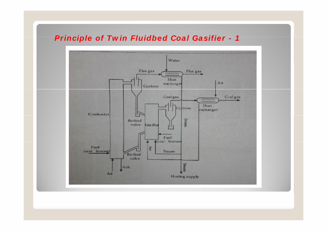
Principle of Twin Fluidbed Coal Gasifier 1Principle of Twin Fluidbed Coal Gasifier - 1

Principle of Twin Fluidbed Coal Gasifier 2
COAL FINES ENTERS GASIFICATION REACTOR, BED TEMPERATURE 850-900 CP
Principle of Twin Fluidbed Coal Gasifier - 2
DRYING, PYROLYSIS OF COAL FINES
VOLATILES REFORMING AND CHAR GASIFICATION WITH STEAM
RESIDUE CHAR LEAVES TO COMBUSTION REACTOR TOGETHER WITH BED MATERIALTHROUGH INCLINED STEAM FLUIDISED CHUTETHROUGH INCLINED STEAM FLUIDISED CHUTE
FINES SEPARATED FROM GAS ALSO TAKEN AND SUPPLEMENTS ADDITIONAL COAL ASREQD. IN COMBUSTION REACTOR
COMBUSTION REACTOR IS FAST FLUIDISED BED. AIR IS USED AS FLUIDISATION AGENT
BED MATERIAL ALSO HEATED UP THERE
PARTICLE SEPARATION FROM FLUE GAS AND ALSO IN CYCLONE, AND SO HOT BEDMATERIAL FLOWS BACK INTO GASIFICATION REACTOR VIA LOOP SEAL(COARSE AND
FINES STREAMS SEPARATELY)
BOTH CONNECTIONS , THE LOOP SEAL AND THE CHUTE ARE FLUIDISED WITH STEAMTHIS EFFECTIVELY PREVENTS GAS LEAKAGE BETWEEN GASIFICATION ANDCOMBUSTION ZONESCOMBUSTION ZONES

Twin Twin FluidbedFluidbed GasifierGasifier ReactorsReactors--Process Flow Process Flow -- 11
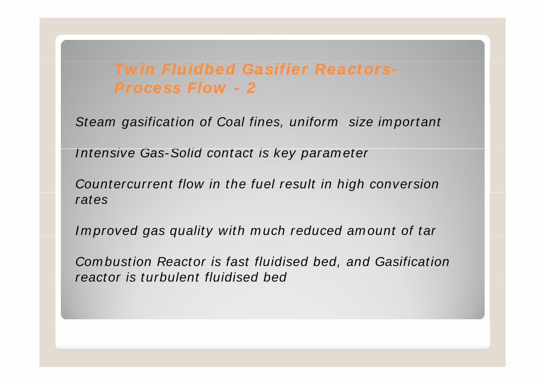
Twin Twin FluidbedFluidbed GasifierGasifier ReactorsReactors--Process Flow Process Flow -- 22
Steam gasification of Coal fines, uniform size important
I t i G S lid t t i k tIntensive Gas-Solid contact is key parameter
Countercurrent flow in the fuel result in high conversion rates
Improved gas quality with much reduced amount of tarp g q y
Combustion Reactor is fast fluidised bed, and Gasification reactor is turbulent fluidised bedreactor is turbulent fluidised bed

Design Concept of Twin Design Concept of Twin FluidbedFluidbed Coal Coal GasifierGasifier (1)(1)
Two reactor units interconnected with circulating solids
The solids loop starts in the combustion reactor where solids are pentrained.
Coarse and fine bed material are separated from the flue gas stream and then sent to the gasification reactor via steam fluidized loop seals (upper loop seal and cyclone loop seal).
The gasification reactor is divided into a sequence of sections by The gasification reactor is divided into a sequence of sections by constrictions whereas solids density is high above these constrictions.

Design Concept of Twin Fluidbed Coal Gasifier (2)
Th fl id d i f th b d t i l i th ifi ti t i The fluid dynamics of the bed material in the gasification reactor is equivalent to a column of stirred vessels.
Optimal residence time distributions are possible depending on the Optimal residence time distributions are possible depending on the location of feedstock input; coarse with low volatiles at higher region ,fines/high volatiles at bottom
From the gasification reactor, the solids mainly flow back into the combustion reactor via a second loop seal connecting the bottom regions of the two reactors (lower loop seal)regions of the two reactors (lower loop seal).
Fine solids entrained and separated from the gasification reactor product gas stream are also directed back into the system.product gas stream are also directed back into the system.

Fluidbed Gasification and Gas purification process
1.Gasifier 2.Heating Furnace 3 Cyclone/Whirlwind 4 & 5.Material sealing valve 6&7 Cyclone1.Gasifier 2.Heating Furnace 3 Cyclone/Whirlwind 4 & 5.Material sealing valve 6&7 Cyclone8.Flash tank 9 Inter cooler 10 Electric oil remover 11 Bag Dust collector 12& 23 Draft Fan13 Gas mist separator 14 & 19 Heat Exchanger 15 Steam Regulator cylinder 18 &16 &17 Feeding machine 20 Coal dewatering device 22 Scrubber
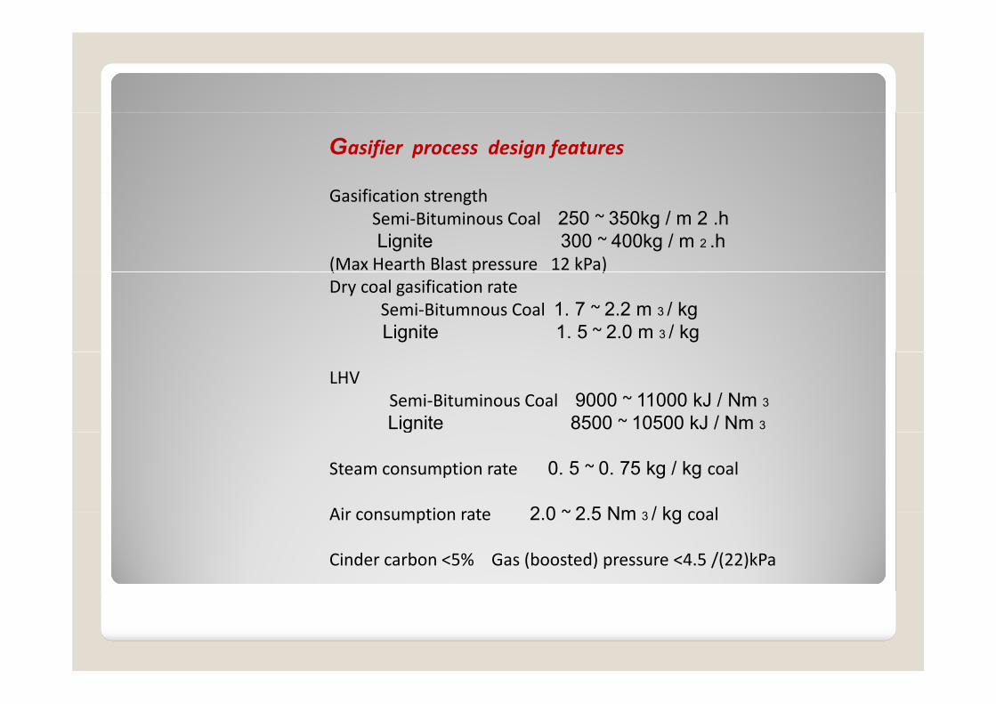
Gasifier process design features
G ifi ti t thGasification strength Semi‐Bituminous Coal 250 ~ 350kg / m 2 .h Lignite 300 ~ 400kg / m 2 .h
(Max Hearth Blast pressure 12 kPa)( p )Dry coal gasification rate
Semi‐Bitumnous Coal 1. 7 ~ 2.2 m 3 / kg Lignite 1. 5 ~ 2.0 m 3 / kg
LHV Semi‐Bituminous Coal 9000 ~ 11000 kJ / Nm 3
Lignite 8500 ~ 10500 kJ / Nm 3g
Steam consumption rate 0. 5 ~ 0. 75 kg / kg coal
Air consumption rate 2 0 ~ 2 5 Nm 3 / kg coalAir consumption rate 2.0 ~ 2.5 Nm 3 / kg coal
Cinder carbon <5% Gas (boosted) pressure <4.5 /(22)kPa

Coal Ashad <18%, Ash fusion point >1150 C, Sad <1%, Net Q >21MJ/kg
Coal Grade desirable
Gas components ( with qualified coal)
G iti
, p , , Q / g
Gas composition
CO 15 to 20%
CO 2 15 to 20%CO 2 15 to 20%
H 2 38 to 43%
CH 4 8 to 13%
O 2 <0.2%
N 2 12 to 17%

Gas Station Process Flowsheet (with gas desulphurisation)Gas Station Process Flowsheet (with gas desulphurisation)
Gas output 11000-13000 nm3/hr
Coal feed 6.5 – 7.5 Ton/hr ; Power connected load : 1075 kW

Gas Desulphurisation Principle
1 Absorption: - feed gas is in countercurrent contact with base solution to absorb H 2 S ; - feed gas is in countercurrent contact with base solution to absorb H 2 S ; H 2 S + Na 2 CO 3 = NaHS + NaHCO 3
2 Sulphur precipitation via high valence metal ion, based on vanadium pentaoxide,
NaHS + NaHCO 3 + 2NaVO 3 = S ↓ + Na 2 V 2 O 5 + Na 2 CO 3 + H 2 O
3. Resulting low-valence metal ions is oxidized by quinone back to high metal ion;
Na 2 V 2 O 5 + 2Q (quinine)+H2O +Na 2 CO3 2 NaVO 3+ 2 HQ (phenol)
4 Regeneration of Quinone: 4. Regeneration of Quinone: By air injection ,HQ is oxidized to quinones state;
2HQ + 1 / 2O 2 = 2Q + H 2 O
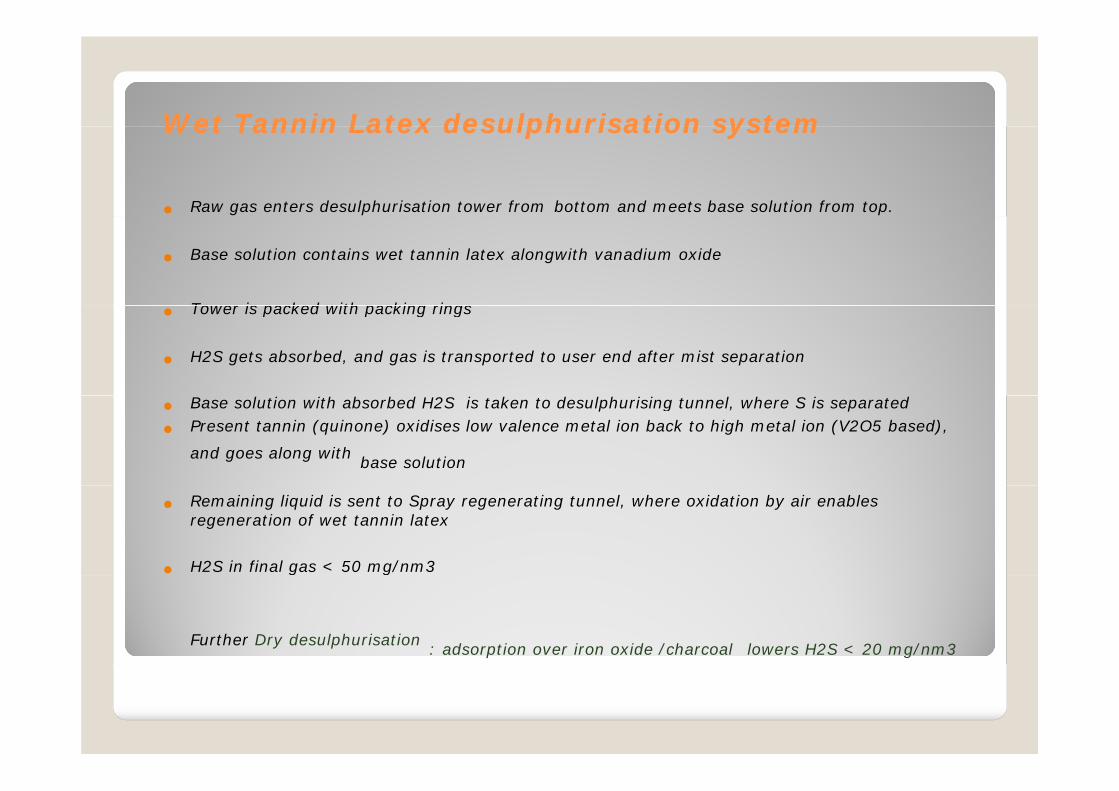
Wet Tannin Latex Wet Tannin Latex desulphurisationdesulphurisation systemsystemWet Tannin Latex Wet Tannin Latex desulphurisationdesulphurisation systemsystem
Raw gas enters desulphurisation tower from bottom and meets base solution from top.
Base solution contains wet tannin latex alongwith vanadium oxide
Tower is packed with packing rings Tower is packed with packing rings
H2S gets absorbed, and gas is transported to user end after mist separation
Base solution with absorbed H2S is taken to desulphurising tunnel, where S is separated
Present tannin (quinone) oxidises low valence metal ion back to high metal ion (V2O5 based),
and goes along with base solution
Remaining liquid is sent to Spray regenerating tunnel, where oxidation by air enables regeneration of wet tannin latex
H2S in final gas < 50 mg/nm3
Further Dry desulphurisation : adsorption over iron oxide /charcoal lowers H2S < 20 mg/nm3

Gas Station 12000 nm3 /hr –gas yield, analysis and calorific value

Gas Station reported performanceGas Station reported performanceCoal analysis: Coal analysis: Moisture 10, After air drying 1.7 %Ash db 7.01 %Volatile matter db 32 5 %Volatile matter db 32.5 %Fixed carbon db 59.39 % Sulphur db 0.33 %CV 6433 kcal/kg CV 6433 kcal/kg
Gas analysis:CO : 23 %CO2: 13%H2 : 35 %CH4 : 7 %N2 22 %N2 : 22 %CV : 2000 kcal/nm3

Application:pp
-Produced fuel gas, is of moderate high calorific value; enables high flame temperature in Kiln/Furnace (suited for I ll t i d ti C l i d B it kil )Iron ore pellet induration , Calcined Bauxite kiln )
- Produced gas could find application in DRI Rotary Kiln substituting Injection Coal therein with better efficiencysubstituting Injection Coal therein , with better efficiency
- High moderate CV syn gas with co-generation of steam in addition for outlets addition for outlets
It enables efficient utilization of low cost fine size coal: Sub-Bituminous low ash Coal/Lignite can be gasified with Sub Bituminous low ash Coal/Lignite can be gasified with high efficiency , who are having high reactivity.

Speaker Credentials: C S BhutoriaSpeaker Credentials: C S Bhutoria
Education: Dual degree in- Science (Maths) :
St X i ’ C ll C l tt 1965St. Xavier’s College, Calcutta 1965and
- Chemical Engineering :Indian Institute of Technology, Bombay
1968 batch1968 batchIndustrial Experience : +40 yrs diversified
Plant and Technology access :
Tangshan Leadhorse Energy Technology Equipment Ltd
Research Centre: R 405 A Ti B ildiRoom 405 A Tiangong Building,No.30,Xueyuan Road , Haidian District, Beijing
P.R.China

Contact channelContact channelChina:
Liu HongbingSYC Global
Thank You For Attention!
Mob: 0086-13816680679E-mail:[email protected]
For Attention!
New Delhi/India:
Syed Danish AliSYC Global PTS
Mob:+91-9555293699E-mail: [email protected]


