
The RS burners series covers a firing range from 81 to 2290 kW, and it has been designedfor use in hot or superheater water boilers, hot air or steam generators, diathermic oilboilers.Operation is "two stage progressive"; the burners are fitted with a microprocessor controlpanel which supplies indication of operation and diagnosis of fault cause.Optimisation of sound emissions is guaranteed by the use of fans with reverse curveblades and sound deadening material incorporated in the air suction circuit.The elevated performance of the fans and combustion head, guarantee flexibility of useand excellent working at all firing rates.The exclusive design ensures reduced dimensions, simple use and maintenance. A widerange of accessories guarantees elevated working flexibility.
TS0046UK03
RS SERIESTWO STAGE PROGRESSIVE GAS BURNERS
RS 28 81/163 ÷ 325 kWRS 38 105/232 ÷ 440 kWRS 50 116/290 ÷ 580 kWRS 70 192/465 ÷ 814 kWRS 100 232/698 ÷ 1163 kWRS 130 372/930 ÷ 1512 kWRS 190 470/1279 ÷ 2290 kW

RS 38
105/232÷440
90/200÷378
10,5/23÷44
12/27÷51
4/9÷17
0,6
0,12
0,42
2,9
11
70
--
RS 50
116/290÷581
100/249÷500
11,6/29÷58
13,5/34÷68
4,5/11÷23
0,75
0,12
0,65
3 - 1,7
13,8 - 8
72
--
CE 0085AP0735
RS 70
192/465÷814
165/400÷700
19/46,5÷81,4
22/54÷95
7,4/18÷32
1,4
0,3
1,1
4,8 - 2,8
25 - 14,6
75
--
CE 0085AP0944
RS 100
232/698÷1163
200/600÷1000
23/70÷116
27/81÷135
9/27÷45
1,8
0,3
1,5
5,9 - 3,4
27,7 - 16
77
--
CE 0085AP0945
3N/50/230-400~(±10%) 3/50/230~(±10%)
SQN90
12
LKS210
15
RS 190
SQN31
15
470/1279÷2290
405/1100÷1970
47/128÷229
55/149÷266
18/50÷89
Straight blades
5,5
1
4,5
15,8 - 9,1
126 - 73
83
--
CE 0085AT0042
RS 130
372/930÷1512
320/800÷1300
37/93÷151
43/108÷176
14,4/36÷59
2,6
0,4
2,2
8,8 - 5,1
57,2 - 33,2
78,5
--
CE 0085AP0946
RS 28
81/163÷325
70/140÷280
8/16÷32
9,4/19÷38
3/6,5÷12,5
0,37
0,12
0,25
2,1
10
40
68
--
CE 0085AP0733
TECHNICAL DATAFu
el /
air
dat
aE
lect
rica
l d
ata
Em
issi
on
sA
ppro
val
Model
Burner operation mode
Modulation ratio at max. output
Type
Run time
Working temperature
Net calorific value G20 gas
G20 gas density
G20 gas delivery
Net calorific value G25 gas
G25 gas density
G25 gas delivery
Net calorific value LPG gas
LPG gas density
LPG gas delivery
Fan
Air temperature
Electrical supply
Auxiliary electrical supply
Control box
Total electrical power
Auxiliary electrical power
Protection level
Motor electrical power
Rated motor current
Motor start up current
Motor protection level
Operation
Sound pressure
Sound power
CO Emission
NOx Emission
Directive
Conforming to
Certification
Servo-motor
s
kW
Mcal/h
°C min./max.
kWh/Nm3
kg/Nm3
Nm3/h
kWh/Nm3
kg/Nm3
Nm3/h
kWh/Nm3
kg/Nm3
Nm3/h
Type
Max. °C
Ph/Hz/V
Ph/Hz/V
Type
kW
kW
IP
kW
A
A
IP
V1 - V2
I1 - I2
dB(A)
W
mg/kWh
mg/kWh
Heat output
Ignitiontransformer
Centrifugal with reverse curve blades
RS 38
105/232÷440
90/200÷378
10,5/23÷44
12/27÷51
4/9÷17
0,56
0,12
0,45
2 - 1,2
9,5 - 5,5
70
--
Two stage progressive
2 ÷ 1
0/40
10
0,71
8,6
0,78
25,8
2,02
60
1/50/230 ~ (±10%)
RMG
44
54
230V - 1x8 kV
1A - 20 mA
Intermittent (at least one stop every 24 h)
< 40
< 130
90/396 - 89/336 - 73/23 - 92/42 EEC
EN 676
Since the Company is constantly engaged in the production improvement, the aesthetic and dimensional features, thetechnical data, the equipment and the accessories can be changed.This document contains confidential and proprietary information of RIELLO S.p.A. Unless authorised, this information shallnot be divulged, nor duplicated in whole or in part.
Reference conditions:Temperature: 20°CPressure: 1000 mbarAltitude: 100 m a.s.l.Noise measured at a distance of 1 meter.
CE 0085AP0734
1/50/230~(±10%)
2

FIRING RATES
Useful working field for choosing the burner
Modulation range (1st stage operation range)
Test conditions conforming to EN 676:Temperature: 20°CPressure: 1000 mbarAltitude: 100 m a.s.l.
0
2
4
6
5
3
1
7
9
8
10
100 kW
0
0
0
20
40
60
50
30
10
70
90
80
100
200 300 400 500 600 700
0
2
4
6
5
3
1
7
9
8
10
11
kW
12
13
14
0
0
0
20
40
60
50
30
10
70
90
80
100
110
120
130
140
15150
100 200 300 400 500 600 700 800 900 1000 1100 1200 1300 1400 1500 1600 1700 1800 1900 2000 2100
RS 50
RS 28
RS 38
RS 70
RS 100
RS 130
RS 190
hP
a (m
bar
)
- 1
mm
H2O
-10
hP
a (m
bar
)
- 1
mm
H2O
-10
Mcal/h100 200 300 400 500 600
Mcal/h
600400200 800 1000 1200 1400 1600 1800 2000 2200 2400
3

The burners are fitted with a butterfly valve to regulate the fueldelivery on 1st and 2nd stage, controlled by a variable profilecam servomotor.
Fuel can be supplied either from the right orleft hand sides.
The gas train can be selected to best fit systemrequirements depending on the fuel outputand pressure in the supply line.The gas train can be “Multibloc“ type(containing the main components in a singleunit) or “Composed” type (assembly of thesingle components).
GAS TRAIN
FUEL SUPPLY
Example of the variable profile cam on RS 70-100-130 burners.
Gas input pipework
Manual valve
Anti-vibration joint
Pressure gauge with pushbutton cock
Filter
Pressure regulator (vertical)
Minimum gas pressure switch
VS safety solenoid (vertical)
VR regulation solenoid (vertical)Two settings: - firing output (rapid opening)
- maximum output (slow opening)
Gasket and flange supplied with the burner
Gas adjustment butterfly valve
Burner
Seal control mechanism for valves 8-9. Accordingto standard EN 676, the seal control is compulsoryfor burners with maximum output above 1200 kW(in gas train with seal control)
Gas train-burner adapter
Maximum gas pressure switch
Combustion head pressure
Pressure downstream from the regulator
Pressure upstream from the filter
Gas train supplied separately, with the code given in the table
Installer’s responsibility
1
2
3
4
5
6
7
8
9
10
11
12
13
14
15
P1
P2
P3
L
L1
MULTIBLOC gas train type MBD 420
L L1
MULTIBLOC gas train type MBC 1200
COMPOSED gas train
L L1
12
P1
11
1015
14 9 8 P2 6 P3
4
3 2 15
12
7
12
13
4
P1
15 1110
14 6
L L1
9 13 8
7
5
4
P3P2 3 2 1
P1
1511
10
14 9 13 6 8
7
5
4
P3P2 3 2 1

MU
LTIB
LOC
GA
S T
RA
INS
Gas trains are approved bystandard EN 676 togetherwith the burner.
The overall dimensions ofthe gas train depends onhow they are constructed.The following table showsthe maximum dimensionsof the gas trains that canbe fitted to RS burners,intake and outlet diametersand seal control if fitted.Please note that the sealcontrol can be installed asan accessory, if not alreadyinstalled on the gas train.T h e m a x i m u m g a spressure of gas train“Multibloc” type is 360mbar, and that one of gastrain “Composed” type is500 mbar.MULTIBLOC guarantees arange of pressure towardthe burner from 3 to 60mbar. For version DN 65and DN 80 is from 20 to 40mbar.The range of pressure inthe MULTIBLOC with flangecan be modified choosingthe stabiliser spring (seegas train accessory).
CO
MP
OS
ED
GA
S T
RA
INS
Example of gas train “MULTIBLOC”type MBD
Name
MBD 407
MBD 410
MBD 412
MBD 412 CT
MBD 415
MBD 415 CT
MBD 420
MBD 420 CT
MBC 1200 SE 50
MBC 1200 SE 50 CT
MBC 1900 SE 65 FC
MBC 1900 SE 65 FC CT
MBC 3100 SE 80 FC
MBC 3100 SE 80 FC CT
Code
3970053
3970054
3970144
3970197
3970180
3970198
3970181
3970182
3970221
3970225
3970222
3970226
3970223
3970227
Ø i
3/4”
1”
1”1/4
1”1/4
1”1/2
1”1/2
2”
2”
2”
2”
DN 65
DN 65
DN 80
DN 80
Ø o
3/4”
3/4”
1”1/2
1”1/2
1”1/2
1”1/2
2”
2”
2”
2”
DN 65
DN 65
DN 80
DN 80
X mm
371
405
433
433
523
523
523
523
573
573
583
583
633
633
Y mm
196
217
217
217
250
250
300
300
161
290
237
300
240
320
Z mm
120
145
145
262
100
227
100
227
425
426
430
430
500
500
Seal Control
-
-
-
Incorporated
-
Incorporated
-
Incorporated
-
Incorporated
-
Incorporated
-
Incorporated
Y
Z X
Øi
Øo
Y
Z X
Øi
Øo
Example of gas train “MULTIBLOC”type MBC 1200
Y
ZX
Øo
Example of gas train“COMPOSED”type MBC 1900 - 3100
Øi
5

The diagrams indicate the minimum pressure drop of the burners with the various gas trains thatcan be matched with them; at the value of these pressure drop add the combustion chamberpressure.The value thus calculated represents the minimum required input pressure to the gas train.
RS 28 RS 28
RS 38 RS 38
PRESSURE DROP DIAGRAM
NATURAL GAS LPG
Gas train
MBD 412 CT
MBD 415
MBD 415 CT
Code
3970197
3970180
3970198
Adapter
-
-
-
Seal Control
Incorporated
Accessory
Incorporated
Gas train
MBD 407
MBD 410
MBD 412
Code
3970053
3970054
3970144
Adapter
3000824
3000824
-
Seal Control
Accessory
Accessory
Accessory
Gas train
MBD 407
MBD 410
MBD 412
MBD 412 CT
Code
3970053
3970054
3970144
3970197
Seal Control
Accessory
Accessory
Accessory
Incorporated
Gas train
MBD 415
MBD 415 CT
MBD 420
MBD 420 CT
Code
3970180
3970198
3970181
3970182
Adapter
-
-
3000822
3000822
Seal Control
Accessory
Incorporated
Accessory
Incorporated
Adapter
3000824
3000824
-
-
kcal/h X 1000
10
25
15
20
30
5
0140 150 200 250 280
mb
ar
G25G20
0
5
15
25
30
35
20
10
40
35
40
45
45
50
55
kcal/h X 1000
10
25
15
20
30
5
0140 150 200 250 280
mb
ar
LPG
35
40
45
kW300200 250163 325
kcal/h X 1000
10
25
15
20
30
5
0
200 300250 350 378
mb
ar
G25G20
0
5
15
25
30
35
20
10
40MBD 410
MBD 412 - 412 CT
MBD 415 - 415 CT
MBD 420 - 420 CT
kcal/h X 1000
10
25
15
20
30
5
0
200 300250 350 378
mb
ar
LPG
MBD 410
MBD 412 - 412 CT
MBD 415 - 415 CT
MBD 420 - 420 CT
kW300 440400250 350232
400
45
35
40 MBD 407ΔP
Com
busti
on h
ead
and
gas
train
Com
busti
on h
ead
Pres
sure
dro
p
ΔP
Com
busti
on h
ead
and
gas
train
Com
busti
on h
ead
Pres
sure
dro
pMBD 410
MBD 412 - 412 CT
MBD 407
MBD 410
MBD 412 - 412 CT
MBD 407
MBD 415 - 415 CT
kW300200 250163 325
kW300 440400250 350232
ΔP
Com
busti
on h
ead
and
gas
train
Com
busti
on h
ead
Pres
sure
dro
p
ΔP
Com
busti
on h
ead
and
gas
train
Com
busti
on h
ead
Pres
sure
dro
p
6

RS 50 RS 50
RS 70 RS 70
NATURAL GAS LPG
Gas train
MBD 407
MBD 410
MBD 412
MBD 412 CT
MBD 415
Code
3970053
3970054
3970144
3970197
3970180
Adapter
3000824
3000824
-
-
-
Seal Control
Accessory
Accessory
Accessory
Incorporated
Accessory
Gas train
MBD 412
MBD 412 CT
MBD 415
MBD 415 CT
Code
3970144
3970197
3970180
3970198
Adapter
-
-
3000843
3000843
Seal Control
Accessory
Incorporated
Accessory
Incorporated
Gas train
MBD 415 CT
MBD 420
MBD 420 CT
MBC 1200 SE
MBC 1200 SE CT
Code
3970198
3970181
3970182
3970221
3970225
Adapter
-
3000822
3000822
3000822
3000822
Seal Control
Incorporated
Accessory
Incorporated
Accessory
Incorporated
Gas train
MBD 420
MBD 420 CT
MBC 1200 SE
MBC 1200 SE CT
Code
3970181
3970182
3970221
3970225
Adapter
-
-
-
-
Seal Control
Accessory
Incorporated
Accessory
Incorporated
10
25
15
20
45
5
0
30
35
40
50
mb
ar
249 300 350 400 450kcal/h X 1000
500
G25G20
0
20
40
50
30
10
60
5
25
45
55
35
15
MBD 410
MBD 412 - 412 CT
MBD 415 - 415 CT
MBD 420 - 420 CT
ΔP
10
20
0
30
40
50
mb
ar
249 300 350 400 450kcal/h X 1000
500
LPG
MBD 410
MBD 412 - 412 CT
MBD 415 - 415 CT
MBD 420 - 420 CT
ΔP
kcal/h X 1000
mb
ar
30
20
40
0
10
50
400 500 600 700
G25G20
0
20
40
50
30
10
60
MBD 415 - 415 CT
MBD 420 - 420 CT
ΔP
kcal/h X 1000
mb
ar
30
20
40
0
10
50
400 500 600 700
LPG
MBD 420 - 420 CT
ΔP
MBD 415 - 415 CT
kW400 550500350 450290 581
60MBD 407
kW600500 700465 814
MBC 1200 SE - 1200 SE CT
MBC 1200 SE - 1200 SE CT
MBC 1200 SE - 1200 SE CT
MBD 412 - 412 CT
kW400 550500350 450290 581
kW600500 700465 814
Com
busti
on h
ead
and
gas
train
Com
busti
on h
ead
Pres
sure
dro
p
Com
busti
on h
ead
and
gas
train
Com
busti
on h
ead
Pres
sure
dro
p
Com
busti
on h
ead
and
gas
train
Com
busti
on h
ead
Pres
sure
dro
p
Com
busti
on h
ead
and
gas
train
Com
busti
on h
ead
Pres
sure
dro
p
7

RS 100 RS 100
RS 130 RS 130
NATURAL GAS LPG
Code
3970221
3970225
3970222
3970226
Adapter
-
-
3000825
3000825
Seal Control
Accessory
Incorporated
Accessory
Incorporated
Gas train
MBD 415
MBD 415 CT
MBD 420
MBD 420 CT
Code
3970180
3970198
3970181
3970182
Adapter
3000843
3000843
-
-
Seal Control
Accessory
Incorporated
Accessory
Incorporated
Gas train
MBC 1200 SE
MBC 1200 SE CT
MBC 1900 SE
MBC 1900 SE CT
Code
3970225
3970222
3970226
3970223
3970227
Adapter
-
3000825
3000825
3000826
3000826
Seal Control
Incorporated
Accessory
Incorporated
Accessory
Incorporated
Gas train
MBD 415
MBD 415 CT
MBD 420
MBD 420 CT
MBC 1200 SE
Code
3970180
3970198
3970181
3970182
3970221
Adapter
3000843
3000843
-
-
-
Seal Control
Accessory
Incorporated
Accessory
Incorporated
Accessory
Gas train
MBC 1200 SE CT
MBC 1900 SE
MBC 1900 SE CT
MBC 3100 SE
MBC 3100 SE CT
kcal/h X 1000
mb
ar
10
20
30
kW
600 900800700 1000
800 900
0
1100700 1000
40
50
1163
G25
0
20
40
50
30
10
60
MBD 415 - 415 CT
MBD 420 - 420 CT
ΔP
kcal/h X 1000m
ba
r
10
20
30
kW
600 900800700 1000
800 900
0
1100700 1000
40
50
1163
LPG
MBD 415 - 415 CT
MBD 420 - 420 CT
ΔP
mb
ar
kW
900800 11001000
1300 140011001000 1200
1200 1300
930 1512
kcal/h X 1000
G25G20ΔP
mb
ar
kW
900800 11001000
1300 1400
0
11001000 1200
1200 1300
930 1512
kcal/h X 1000
LPG
MBD 415 - 415 CT
MBD 420 - 420 CT
ΔP
MBC 1200 SE - 1200 SE CT
Com
busti
on h
ead
and
gas
train
Com
busti
on h
ead
Pres
sure
dro
p
Com
busti
on h
ead
and
gas
train
Com
busti
on h
ead
Pres
sure
dro
p
Com
busti
on h
ead
and
gas
train
Com
busti
on h
ead
Pres
sure
dro
p
Com
busti
on h
ead
and
gas
train
Com
busti
on h
ead
Pres
sure
dro
p
10
40
20
30
50
0
60
70
80
90
100
110
0
20
40
50
30
10
60
70
80
90
100
110
120
130
140
MBD 415 - 415 CT
MBD 420 - 420 CT
MBC 3100 SE - 3100 SE CTMBC 1900 SE - 1900 SE CTMBC 1200 SE - 1200 SE CT
10
40
20
30
50
60
70
80
90
100
110
60
70
70
80
90
MBC 1900 SE - 1900 SE CTMBC 1200 SE - 1200 SE CT
60
70G20
MBC 1900 SE - 1900 SE CT
MBC 1200 SE - 1200 SE CT
8

Please contact the Riello Burner Technical Office for different pressure levels from thoseabove indicated and refer to the technical manual for the correct choice of the spring.
In LPG plants, Multibloc gas trains do not operate below 0°'a1C. They are only suitable forgaseous LPG (liquid hydrocarbons destroy the seal materials).
MBC 1200 gas train: the minimum operating pressure (*) is higher or equal to 10 mbar. The gastrain has to be installed next to the burner (if needed, only with the adapters listed in thecatalogue) and it has to operate in its own working field.
MBC 1900-3100 gas train: the minimum operating pressure (*) is higher or equal to 15 mbar.The gas train has to be installed next to the burner (if needed, with the adapters listed in thecatalogue) and it has to operate in its own working field.
(*) it is the upstream gas train pressure in full load operation conditions.
note
RS 190
mb
ar
20
80
40
60
100
kW
11001000 13001200
1700 1800
0
15001400 1600
1400 1500
19001279 2290
G25G20
0
40
80
100
60
20
120
kcal/h X 1000
MBC 1900 SE 65 FC - 1900 SE 65 FC CT
MBC 3100 SE 80 FC - 3100 SE 80 FC CT
MBD 420 - 420 CT
1600 1700 1800 1900
1200 2000 2100
2000
RS 190
mb
ar
20
80
40
60
100
kW
11001000 13001200
1700 1800
0
15001400 1600
1400 1500
19001279 2290
LPG
kcal/h X 1000
MBD 415 - 415 CT
MBD 420 - 420 CT
1600 1700 1800 1900
1200 2000 2100
2000
NATURAL GAS LPG
140
MBC 1200 SE 50 FC - 1200 SE 50 FC CT
MBC 1900 SE 65 FC - 1900 SE 65 FC CT
MBC 3100 SE 80 FC - 3100 SE 80 FC CTMBC 1200 SE 50 FC - 1200 SE 50 FC CT
Code
3970225
3970222
3970227
3970223
3970228
Adapter
3010128
3000831
3000831
3000832
3000832
Seal Control
Incorporated
Accessory
Incorporated
Accessory
Incorporated
Gas train
MBD 415
MBD 415 CT
MBD 420
MBD 420 CT
MBC 1200 SE 50
Code
3970180
3970198
3970181
3970182
3970221
Adapter
3000843
3000843
-
-
3010128
Seal Control
Accessory
Incorporated
Accessory
Incorporated
Accessory
Gas train
MBC 1200 SE 50 CT
MBC 1900 SE 65 FC
MBC 1900 SE 65 FC CT
MBC 3100 SE 80 FC
MBC 3100 SE 80 FC CT
ΔP
Com
busti
on h
ead
and
gas
train
Com
busti
on h
ead
Pres
sure
dro
p
ΔP
Com
busti
on h
ead
and
gas
train
Com
busti
on h
ead
Pres
sure
dro
p
9

SELECTING THE FUEL SUPPLY LINES
0,1 0,2 0,3 0,4 0,5 0,6 0,7 0,8 1 2 3 4 5 106 20
50 60 10080 200 400 800 1000600
3
69
12152230
45 61 76 95 122 152 V
PRESSURE DROP (mbar)
1 2 3 4 5 6 7 8 10 20 30 40
PIPE DIAMETER
1,4
PIPE LENGTH (m)
1/2
3/4
1"
1" 1/2
6"
1" 1/4
4"
3"2" 1/22"
= Gas output Nmc/h
f1 - G20
= 0,62 - G251,18 - G31{
fV
15,34
Figure A
The following diagram enables pressure drop in a pre-existing gas line to be calculated and to select thecorrect gas train.The diagram can also be used to select a new gas line when fuel output and pipe length are known. Thepipe diameter is selected on the basis of the desired pressure drop. The diagram uses methane gas asreference; if another gas is used, conversion coefficient and a simple formula (on the diagram) transformthe gas output to a methane equivalent (refer to figure A). Please note that the gas train dimensions musttake into account the back pressure of the combustion chamber during operations.
Control of the pressure drop in an existing gas line or selecting a new gas supply line.The methane output equivalent is determined by the formula fig. A on the diagram and the conversioncoefficient.
Once the equivalent output has been determined on the delivery scale ( ), shown at the top of thediagram, move vertically downwards until you cross the line that represents the pipe diameter; at thispoint, move horizontally to the left until you meet the line that represents the pipe length.Once this point is established you can verify, by moving vertically downwards, the pipe pressure dropof on the botton scale below (mbar).By subtracting this value from the pressure measured on the gas meter, the correct pressure value willbe found for the choice of gas train.
Example: - gas used G25- gas output 9.51 mc/h- pressure at the gas meter 20 mbar- gas line length 15 m- conversion coefficient 0.62 (see figure A)
- equivalent methane output = 9.51 = 15.34 mc/h0.62
- once the value of 15.34 has been identified on the output scale ( ), moving vertically downwards youcross the line that represents 1" 1/4 (the chosen diameter for the piping);
- from this point, move horizontally to the left until you meet the line that represents the length of 15 mof the piping;
- move vertically downwards to determine a value of 1.4 mbar in the pressure drop botton scale;- subtract the determined pressure drop from the meter pressure, the correct pressure level will be found
for the choice of gas train;
- correct pressure = ( 20-1.4 ) = 18.6 mbar
V
V
V
10

Different lengths of the combustion head can be chosen for theRS series of burners.
The choice depends on the thickness of thefront panel and the type of boiler.
Depending on the type of generator, check that thepenetration of the head into the combustion chamber iscorrect.
The internal positioning of the combustion head can easilybe adjusted to the maximum defined output by adjustinga screw fixed to the flange.
The ventilation circuit produces low noise levels with highperformance pressure and air output, inspite of the compact
dimensions.
Except for the RS 190 model, the use of reversecurve blades and sound-proofing material keeps noise level verylow. In the RS 190 model, noise has been reduced by the specialdesign of the air suction circuit.
A variable profile cam connects the fuel and air regulations, toobtain a perfect control of combustion during the change ofstage. When the burner is not operating the servomotor closescompletely the air damper to reduce heat dispersion from theboiler.A minimum air pressure switch stops the burner when there isan insufficient quantity of air at the combustion head.
COMBUSTION HEAD
VENTILATION
Example of a RS burner combustion head
Flame dimensions
Example of the air damper onRS 28 - 38 - 50 burners
Example:Burner thermal output = 2000 kW;L flame (m) = 2,7 m (medium value);D flame (m) = 0,8 m (medium value)
D
L
Burner output (MW)
3
1
2
4
Flam
e le
ng
ht
(m)
Flam
e d
iam
eter
(m
)
0 0
0,5
1
1,5
2
0 21 3 4
D max
D min
L max
L min
11

ADJUSTMENT
BURNER OPERATION MODE
On “two stage” operation, the burnergradually adapts the output to therequested level, by varying betweentwo pre-set levels (see picture A).
All RS series burners are fitted with a new microprocessor control panel for the supervision duringintermittent operation.For helping the commissioning and maintenance work, there are two main elements:
The lock-out reset button is the central operating element for resetting the burner controland for activating / deactivating the diagnostic functions.
The multi-color LED is the central indication element for visual diagnosis and interfacediagnosis.
Both elements are located under the transparent cover of lock-out reset button, as showed below.
There are two diagnostic choices, for indication of operation and diagnosis of fault cause:
- visual diagnosis :
- interface diagnosis : by the interface adapterand a PC with dedicateds o f t w a r e o r b y apredisposed flue gasanalyzer (see paragraphaccessories).
Switch
Switch
COMPUTER
or
FLUE GASANALYSER
INTERFACE ADAPTER
Picture A
Ou
tpu
tC
on
tro
lled
var
iab
le
Two stage operation
bar°C
MAX
MIN
Time
Time
12

RS 28-38-50-100-130-190
START UP CYCLE
time (s)
43 45
28
46
53
3
2
3
Off Yellow Green
0 s The burner begins the firing cycle.2 s The motor starts: pre-purge phase.43 s Ignition electrode sparks; safety valve VS and
adjustment valve VR open.45 s The spark goes out.53 s Output can be increased; start up cycle is concluded.
M
0
2°1°
0
2°1°
TL
TR
VRVS
RMGLED*
0
M
Indication of operation:
In normal operation, the various statues areindicated in the form of colour codes accordingto the table below.The interface diagnosis (with adapter) can beactivated by pressing the lock-out button for> 3 seconds.
Color code table
Operation statues
Stand-byPre-purgingIgnition phaseFlame OKPoor flameUndervoltage, built-in fuseFault, alarmFlame simulation
Color code table
LED off
Diagnosis of fault causes:
After lock-out has occurred, the red signal lamp is steady on. In this status, the visual fault diagnosisaccording to the error code table can be activated by pressing the lock-out reset button for > 3 seconds.The interface diagnosis (with adapter) can be activated by pressing again the lock-out button for > 3seconds.
The blinkers of red LED are a signal with this sequence:
(e.g. signal with n° 3 blinks – faulty air pressure monitor)
LED off3 sec. 3 sec. 3 sec.
Error code table
Possible cause of fault
No establishment of flame at the end of safety time : - faulty or soiled fuel valves- faulty or soiled flame detector- poor adjustment of burner, no fuel- faulty ignition equipment
Faulty air pressure monitor
Extraneous light or simulation of flame on burner start up
Loss of flame during operation : - faulty or soiled fuel valves- faulty or soiled flame detector- poor adjustment of burner
Wiring error or internal fault
Blink code
13

“TWO STAGE” OPERATION - Single-phase power supply
WIRING DIAGRAMS
Electrical connections must bemade by qualified and skilledpersonnel, according to the localregulations.
Example of plugs and sockets for electricalconnections for the RS 28-38-50 models
RS 28-38 - without seal control
RS 38-50 - without seal control RS 38-50 - with seal control
RS 28-38 - with seal control
h1 - Hour meterh2 - Hour meterIN - Manual switchMB - Burner auxiliary terminal boardX4 - 4 pin plugX6 - 6 pin plugX7 - 7 pin plugPG - Minimum gas pressure switchS - External lock-out signalTR - High/low flame setting thermostatTL - Threshold thermostatTS - Safety thermostatVR - Adjustment valveVS - Safety valveT6A - 6A fuse
h1 - Hour meterh2 - Hour meterIN - Manual switchXP - Seal control plugX4 - 4 pin plugX6 - 6 pin plugX7 - 7 pin plugPG - Minimum gas pressure switchS - External lock-out signalS1 - External lock-out signal on the seal controlTR - High/low flame setting thermostatTL - Threshold thermostatTS - Safety thermostatVPS - Seal controlVR - Adjustment valveVS - Safety valveT6A - 6A fuse
“TWO STAGE” OPERATION - Triple-phase power supply
h1 - Hour meterh2 - Hour meterIN - Manual switchMB - Burner auxiliary terminal boardX4 - 4 pin plugX5 - 5 pin plugX6 - 6 pin plugX7 - 7 pin plugPG - Minimum gas pressure switchS - External lock-out signalTR - High/low flame setting thermostatTL - Threshold thermostatTS - Safety thermostatVR - Adjustment valveVS - Safety valveT6A - 6A fuse
h1 - Hour meterh2 - Hour meterIN - Manual switchXP - Seal control plugX4 - 4 pin plugX5 - 5 pin plugX6 - 6 pin plugX7 - 7 pin plugPG - Minimum gas pressure switchS - External lock-out signalS1 - External lock-out signal on the seal controlTR - High/low flame setting thermostatTL - Threshold thermostatTS - Safety thermostatVPS - Seal controlVR - Adjustment valveVS - Safety valveT6A - 6A fuse
T6 T8
PP
P P
N123X6 PhN123X6 Ph N L1L3 L2X5 X7L1
PE N L
S3 T2 T1B4
T6A
TSTL
I N
1,5 mm2
S
N
T6A
PE
1,5 mm2
L1L3 L2
N L1L3 L2X5
T6A
PE
1,5 mm2
L1L3 L2
T8 T7 T6
TR
X7L1X4
PE N L
S3 T2 T1B4
T6A
TSTL
I N
1,5 mm2
S
NB5
N V
VR VS
S1
NT8 T6T7 L1
PG
XP
VPS
B5
PG
N V
VR VSh1
ϑ Pϑ P
ϑ Ph1
ϑ Pϑ P
h2
~50Hz 230V ~50Hz 230V
X7L1
PE N L
S3 T2 T1B4
T6A
TSTL
I N
1,5 mm2
S
N
h1
ϑ Pϑ P
~50Hz 230V
P
P P
N123X6 Ph
PG
N V
VR VS
T8 T7 T6 B5X4
TR
h2
ϑ P
T6 T8
P
T8 T7 T6
TR
X7L1X4
PE N L
S3 T2 T1B4
T6A
TSTL
I N
1,5 mm2
S
NN123X6 Ph B5
N V
VR VS
S1
NT8 T6T7 L1
PG
XP
VPS
B5
ϑ Ph1
ϑ Pϑ P
h2
~50Hz 230V
T8 T7 T6 B5X4
TR
h2
ϑ P
~M3~50Hz 230V3~3N 50Hz 400/230V ~M3~50Hz 230V3
~3N 50Hz 400/230V
14

EMISSIONS
The emission data has been measured inthe various models at maximum output,according to EN 676 standard.
The following table shows the supply lead sections and the type of fuse to be used.
Table A
RS 70-100-130-190 - without seal control RS 70-100-130-190 - with seal control
MB - Burner terminal boardIN - Manual switchPG - Minimum gas pressure switchS - External lock-out signalTR - High/low flame setting thermostatTL - Threshold thermostatTS - Safety thermostatVR - Adjustment valveVS - Safety valveT6A - 6A fuseF - Fuse (see table A)L - Lead section (see table A)
MB - Burner terminal boardIN - Manual switchXP - Seal control plugPG - Minimum gas pressure switchS - External lock-out signalS1 - External lock-out signal on the seal controlTR - High/low flame setting thermostatTL - Threshold thermostatTS - Safety thermostatVPS - Seal controlVR - Adjustment valveVS - Safety valveT6A - 6A fuseF - Fuse (see table A)L - Lead section (see table A)
RS 28 RS 38 RS 50
230V
T61,5
400V
T61,5
230V
T61,5
400V
T61,5
RS 70 RS 100 RS 130
230V
T101,5
400V
T61,5
230V
T161,5
400V
T101,5
230V
T161,5
400V
T101,5
RS 190
230V
T252,5
400V
T202,5
Model
A
mm2
FL
400V
T61,5
230V
T61,5
RS 38
230V
T61,5
P
L1 L2 L3 N LMB 1 2
PE L1 L2 L3
T6A
N L
TS STL
IN
~50Hz 230V
3
F
7 8 N V
TR
4 5 6T8 T6
S1
NT8 T6T7 L1
PG
XP
VPS
B5
VN
VS VR
~
ϑ Pϑ P ϑ P
~M3~50Hz 230V33N 50Hz 400/230V
L
P
P P
L1 L2 L3 N LMB 1 2
L
PE L1 L2 L3
T6A
N L
TS STL
IN
~50Hz 230V
3
F
~M3
4 5
PG
N V
VRVS
6 7 8 N V
TR
~50Hz 230V3~3N 50Hz 400/230V
ϑ Pϑ P ϑ P
CO EMISSIONS
mg
/kW
h
0
10
20
30
40
50
RS 28 RS 38 RS 50 RS 70 RS 100 RS 130 RS 190
NOISE EMISSIONS
dB
(A)
0
20
40
60
80
100
RS 28 RS 38 RS 50 RS 70 RS 100 RS 130 RS 190
NO2 EMISSIONS
mg
/kW
h
0
50
100
150
75
25
RS 28 RS 38 RS 50 RS 70 RS 100 RS 130 RS 190
125
15

OVERALL DIMENSIONS (mm)
BURNERS
PACKAGING
X - X (1)
Z
Y
RS 28
RS 38
RS 50
RS 70
RS 100
RS 130
RS 190
BURNER – BOILER MOUNTING FLANGE
Ø
D2
45°
45°
D1
RS 70 - 100 - 130
A
D
B C
O - O (1)
V
E
I
F - F (1)L
N
M
H
RS 28
RS 38
RS 50
RS 70
RS 100
RS 130
RS 190
A
D
B C
RS 190
RS 28 - 38 - 50
A
D
M8M8M8M12M12M12M16
ØD2160160160185185195230
224224224
275 - 325275 - 325275 - 325325 - 368
D1
Model X - X (1) Y kg
872 - 1007872 - 1007872 - 10071190 - 13251190 - 13251190 - 1325
1250
540540540692692692785
38404170737682
Z
550550550740740740725
Model
Model A B DC HF - F (1) L O - O (1)I VE M N
---
296312338366
476476476511527553681
352352352430430430430
---
215215215315
580580580840840840856
164164164214214214230
108108108134134134150
474474474555555555555
1”1/21”1/21”1/2
2”2”2”
DN80
168168168221221221186
S
140140152179179189222
810810810
1161 - 12961161 - 12961161 - 1296
1312
O - O (1)
S
367367367
----
(1) Length with extended combustion head
(1) Length with extended combustion head
RS 28
RS 38
RS 50
RS 70
RS 100
RS 130
RS 190
O - O (1)
216 - 351216 - 351216 - 351250 - 385250 - 385280 - 415372 - 530
V
N
E
I
F - F (1)L
H
M
E
FF (1)
H
I
N
MV
L
16

INSTALLATION DESCRIPTION
All the burners have slide bars, for easier installationand maintenance.
After drilling the boilerplate, using the supplied gasketas a template, dismantle the blast tube from the burnerand fix it to the boiler.
Adjust the combustion head.
Fit the gas train, choosing this on the basis of themaximum output of the boiler and considering theenclosed diagrams.
Refit the burner casing to the slide bars.
Close the burner, sliding it up to the flange.
Make the electrical connections to the boiler followingthe wiring diagrams included in the instructionhandbook.
Turn the motor to check rotation direction (if it is athree-phase motor).
Perform a first ignition calibration on the gas train.
On start up, check:- Gas pressure at the combustion head (to max. and
min. output)- Combustion quality, in terms of unburned substances
and excess air.
Installation, start up and maintenance must be carriedout by qualified and skilled personnel.All operations must be performed in accordance with thetechnical handbook supplied with the burner.
BURNER SETTING
ELECTRICAL CONNECTIONS AND START-UP
17

BURNER ACCESSORIES
Extended head kit
“Standard head” burners can be transformed into “extended head”versions, by using the special kit. The KITS available for the variousburners, giving the original and the extended lengths, are listed below.
Kit code
RS 28RS 38RS 50RS 70RS 100RS 130RS 190
Burner
3010076
3010077
3010078
3010117
3010118
3010119
3010196
‘Extended head’length (mm)
351351351385385415530
216216216250250280372
‘Standard head’length (mm)
Post-ventilation kit
To prolong ventilation for approximately 5 seconds after opening of thermostats chain, a special kitis available.
RS 28 - 38 - 50 - 70 - 100 - 130 - 190Burner Kit code
3010004
Post-ventilation kit
Spacer kit
If burner head penetration into the combustion chamber needs reducing, varying thickness spacersare available, as given in the following table:
RS 28 - 38 - 50RS 70 - 100 - 130RS 190
Burner Kit code
3010095
3010129
3000722S
Spacer thickness S (mm)
90135102
Spacer kit
Extended head kit
Continuous ventilation kit
If the burner requires continuous ventilation in the stages without flame, a special kit is available asgiven in the following table:
RS 28 - 38 - 50 - 70 - 100 - 130 - 190Burner Kit code
3010094
Continuous ventilation kit
18

RS 28RS 38RS 50RS 70RS 100RS 130RS 190
Burner
LPG kit
Kit code for‘extended head’
Kit code for‘standard head’
3010089
3010090
3010165
3010098
3010100
3010102
-
LPG kit
For burning LPG gas, a special kit is available to be fitted to the combustion head on the burner, asgiven in the following table:
3010089
3010090
3010165
3010097
3010099
3010101
3010166
Sound proofing box
If noise emission needs reducing even further, sound-proofing boxes are available, as given in thefollowing table:
RS 28 - 38 - 50RS 70 - 100 - 130RS 190
Burner Box code
3000777
3000778
3000779
C2C3C4
Box type
111414
Average noisereduction [dB(A)]
RS 28RS 38RS 50RS 70RS 100RS 130RS 190
Burner
Town gas kit
Town gas kit
For burning Town gas, a special kit is available:
3010283
3010284
3010285
3010286
3010287
3010288
3010297
(*) Without CE certification
Kit code forstandard head (*)
3010283
3010284
3010285
3010286
3010287
3010288
3010297
Kit code forextended head (*)
Sound proofing box
19

Ground fault interrupter kit
A “Ground fault interrupter kit” is available as a safety device for electrical system fault.
RS 28 - 38 - 50RS 70 - 100 - 130 - 190
Burner Kit code
3010321
3010329
Status Panel kit
The RS burners can be equipped with an exclusive electronic device “Status Panel” which continuouslymonitors and displays all the burner operational modes and picks up any anomalies during theoperational cycle.
RS 28 - 38 - 50 - 70 - 100 - 130 - 190Burner Kit code
3010322
Burner Kit code
Vibration reduction kit
The kit allow you to improve flame stability in some applications, where the boiler/flue assemblyis liable to resonate.
Vibration reduction kit
RS 28 TC - RS 28 TLRS 38 TC - RS 38 TLRS 50 TC - RS 50 TLRS 70 TC - RS 70 TLRS 100 TC - RS 100 TLRS 130 TCRS 130 TLRS 190 TC
3010198
3010199
3010200
3010201
3010202
3010373
3010374
3010375
Ground fault interrupter kit
Status Panel kit
20

Interface adapter kit
To connect the flame control panel to a personal computer for the transmission of operation, faultsignals and detailed service information, an interface adapter with PC software are available.
Burner Kit code
3002719
Interface adapter kit
RS 28 - 38 - 50 - 70 - 100 - 130 - 190
Connection flange kit
A kit is available for use where the burner opening on the boiler is of excessive diameter.
RS 28 - 38 - 50Burner Kit code
3010138
21
Connection flange kit

GAS TRAIN ACCESSORIES
Adapters
When the diameter of the gas train is different from the set diameter of the burners, an adapter mustbe fitted between the gas train and the burner. The following table lists the adapters for variousburners.
Adapters
Burner Gas train Dimensions Adapter code
1" 1/2 2"
1"1/23/4"
2" 1"1/2
1"1/2 2"
1"1/23/4"
1"1/23/4"
2" 1"1/2
1"1/2 2"
RS 28
RS 38
RS 50
RS 70
RS 100
RS 130
RS 190
MBD 407 - 410
MBD 407 - 410
MBD 420
MBD 407 - 410
MBD 420 - MBC 1200
MBD 415
MBC 1900
MBC 3100
MBD 415
MBC 1900
MBC 3100
MBD 415
MBC 1900
MBC 3100
MBD 420 - MBC 1200
MBC 1900
MBC 3100
DN 65
DN 80
DN 80
DN 80
3000824
3000824
3000822
3000824
3000822
3000843
3000825
3000826
3000843
3000825
3000826
3000843
3000825
3000826
3010128
3000831
3000832
DN 65 2"1/2
2"
1"1/2
1"1/2
2"
DN 65 2"1/2
DN 80 2"1/2 2"
2"
DN 80
DN 65 2"1/2
DN 80 2"1/2 2"
1"1/2
2"
DN 65 2"1/2
DN 80 2"1/2 2"
22

Stabiliser springs
Stabiliser spring
Accessory springs are available to vary the pressure range of the gas train stabilisers. The followingtable shows these accessories with their application range.
Please refer to the technical manual for the correct choice of spring.
Gas train Spring codeSpring
Seal control kit
To test the valve seals on the gas train, a special “seal control kit” is available. The valve seal controldevice is compulsory (EN 676) on gas trains to burners with a maximum output over 1200 kW. Thesealing control is type VPS 504.
All modelsBurner Kit code
Seal control kit
Gas train
3010367All models
23
MBC 1900MBC 3100MBC 5000
3010381
3010382
3010383
3010384
White from 4 to 20 mbarRed from 20 to 40 mbar
Black from 40 to 80 mbarGreen from 80 to 150 mbar

R S 130 TC FS1 230/50-60
A specific index guides your choice of burner fromthe various models available in the RS series.Below is a clear and detailed specification descriptionof the product.
SPECIFICATION
BASIC DESIGNATION
EXTENDED DESIGNATION
DESIGNATION OF SERIES
3/230-400/50
Size
Fuel : S Natural GasL Light oilLS Light oil/MethaneN Heavy oil
Series : R
ID:Differentialswitch
Setting : /1 Single stage /E Electronic cam... Two stage /P Proportioning air/gas valve/M Modulating /EV Electronic cam predisposed for variable speed (with inverter)
Emission : ... Class 1 EN267 - EN676MZ Class 2 EN267 - EN676BLU Class 3 EN267 - EN676
MXClass 2 EN267Class 3 EN676
Head : TC Standard headTL Extended head
Flame control system : FS1 Standard (1 stop every 24 h)FS2 Continuous working (1 stop every 72 h)
Auxiliary voltage :230/50-60 230V/50-60Hz110/50-60 110V/50-60Hz
Electrical supply to the system :1/230/50 1/230V/50Hz3/230/400/50 3/230V/400V/50Hz1/220-230/60 1/220-230V/60Hz3/220-230/380-400/60 3/220-230V/60Hz - 3/380-400V/60Hz3/254-265/440-460/60 3/254-265/60Hz - 3/440-460V/60Hz
24
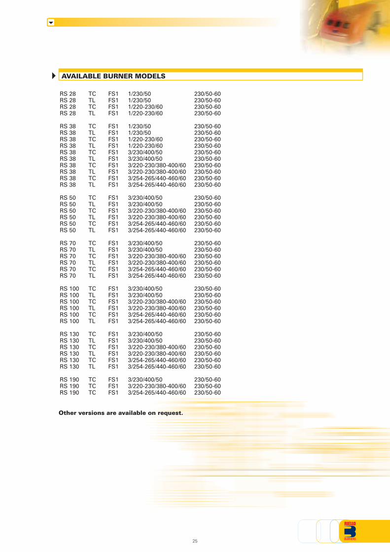
AVAILABLE BURNER MODELS
Other versions are available on request.
RS 28 TC FS1 1/230/50 230/50-60RS 28 TL FS1 1/230/50 230/50-60RS 28 TC FS1 1/220-230/60 230/50-60RS 28 TL FS1 1/220-230/60 230/50-60
RS 38 TC FS1 1/230/50 230/50-60RS 38 TL FS1 1/230/50 230/50-60RS 38 TC FS1 1/220-230/60 230/50-60RS 38 TL FS1 1/220-230/60 230/50-60RS 38 TC FS1 3/230/400/50 230/50-60RS 38 TL FS1 3/230/400/50 230/50-60RS 38 TC FS1 3/220-230/380-400/60 230/50-60RS 38 TL FS1 3/220-230/380-400/60 230/50-60RS 38 TC FS1 3/254-265/440-460/60 230/50-60RS 38 TL FS1 3/254-265/440-460/60 230/50-60
RS 50 TC FS1 3/230/400/50 230/50-60RS 50 TL FS1 3/230/400/50 230/50-60RS 50 TC FS1 3/220-230/380-400/60 230/50-60RS 50 TL FS1 3/220-230/380-400/60 230/50-60RS 50 TC FS1 3/254-265/440-460/60 230/50-60RS 50 TL FS1 3/254-265/440-460/60 230/50-60
RS 70 TC FS1 3/230/400/50 230/50-60RS 70 TL FS1 3/230/400/50 230/50-60RS 70 TC FS1 3/220-230/380-400/60 230/50-60RS 70 TL FS1 3/220-230/380-400/60 230/50-60RS 70 TC FS1 3/254-265/440-460/60 230/50-60RS 70 TL FS1 3/254-265/440-460/60 230/50-60
RS 100 TC FS1 3/230/400/50 230/50-60RS 100 TL FS1 3/230/400/50 230/50-60RS 100 TC FS1 3/220-230/380-400/60 230/50-60RS 100 TL FS1 3/220-230/380-400/60 230/50-60RS 100 TC FS1 3/254-265/440-460/60 230/50-60RS 100 TL FS1 3/254-265/440-460/60 230/50-60
RS 130 TC FS1 3/230/400/50 230/50-60RS 130 TL FS1 3/230/400/50 230/50-60RS 130 TC FS1 3/220-230/380-400/60 230/50-60RS 130 TL FS1 3/220-230/380-400/60 230/50-60RS 130 TC FS1 3/254-265/440-460/60 230/50-60RS 130 TL FS1 3/254-265/440-460/60 230/50-60
RS 190 TC FS1 3/230/400/50 230/50-60RS 190 TC FS1 3/220-230/380-400/60 230/50-60RS 190 TC FS1 3/254-265/440-460/60 230/50-60
25

BurnerMonoblock forced draught gas burner with two stage operation, fully automatic, made up of:- Air suction circuit lined with sound-proofing material- Fan with reverse curve blades (straight blades on the 190 model) high performance with low sound
emissions- Air damper for air flow setting and butterfly valve for regulating fuel output on 1st and 2nd stage
controlled by a servomotor with variable cam- Starting motor at 2800 rpm, three-phase 400V with neutral, 50Hz (available also single-phase, 230V,
50Hz for the RS 28 and 38 models)- Combustion head, that can be set on the basis of required output, fitted with:
- stainless steel end cone, resistant to corrosion and high temperatures- ignition electrodes- ionisation probe- gas distributor- flame stability disk
- Minimum air pressure switch stops the burner in case of insufficient air quantity at the combustionhead
- Microprocessor-based flame control panel, with diagnostic functions- Plug and socket for electrical connections (RS 28-38-50 models)- Burner on/off selection switch- 1st - 2nd stage manual switch- Flame inspection window- Slide bars for easier installation and maintenance- Protection filter against radio interference- IP 44 electric protection level.
Gas trainFuel supply line, in the MULTIBLOC configuration (from a diameter of 3/4” until a diameter 2”) orCOMPOSED configuration (from a diameter of DN 65 until a diameter of DN 100), fitted with:- Filter- Stabiliser- Minimum gas pressure switch- Safety valve- Valve seal control (for output > 1200 kW)- One stage working valve with ignition gas output regulator.
Conforming to:- 89/336/EEC directive (electromagnetic compatibility)- 73/23/EEC directive (low voltage)- 92/42/EEC directive (performance)- 90/396/EEC directive (gas)- EN 676 (gas burners).
Standard equipment- 1 gas train gasket- 1 flange gasket- 4 screws for fixing the flange- 1 thermal screen- 4 screws for fixing the burner flange to the boiler- Wiring loom fittings for the electrical connection (RS 28 - 38 - 50)- 2 slide bar extensions (for extended head models and RS 190 model)- Instruction handbook for installation, use and maintenance- Spare parts catalogue.
Available accessories to be ordered separately- Extended head kit- Spacer kit- Continuous ventilation kit- Post-ventilation kit- Sound-proofing box- LPG kit- Town gas kit- Vibration reduction kit- Status panel kit- Ground fault interrupter kit- Interface adapter kit- Connection flange kit- Gas train adapter- Seal control kit- Stabiliser spring.
PRODUCT SPECIFICATION
26

27

ISO 9001 Cert. n. 0061
RIELLO S.p.A. - Via Ing. Pilade Riello, 5 - 37048 San Pietro di Legnago (VR) ItalyTel. ++39.0442630111 - Fax ++39.044221980
Internet: http://www.rielloburners.com - E-mail: [email protected]
Since the Company is constantly engaged in the production improvement, the aesthetic anddimensional features, the technical data, the equipment and the accessories can be changed.
This document contains confidential and proprietary information of RIELLO S.p.A.Unless authorised, this information shall not be divulged, nor duplicated in whole or in part.
Line
agra
fica.
it

RIELLO S.p.A. - Via degli Alpini, 1 - 37045 LEGNAGO (VR) ItalyTel. ++39.0442630111 - Fax ++39.044221980
Internet: http://www.rielloburners.com - E-mail: [email protected] 9001 Cert. n. 0061
RL SERIES
TS0035UK01
RL 28 95/166 ÷ 332 kWRL 38 118/237 ÷ 450 kWRL 50 148/296 ÷ 593 kWRL 70 255/474 ÷ 830 kWRL 100 356/711 ÷ 1186 kWRL 130 486/948 ÷ 1540 kWRL 190 759/1423 ÷ 2443 kW
TWO STAGE LIGHT OIL BURNERS
The RL series of burners covers a firing range from 95 to 2443 kW, and they have beendesigned for use in hot or superheater water boilers, hot air or steam generators, diathermicoil boilers.Operation is "two stage"; the burners are fitted with an electronic device STATUS PANEL,which supplies complete diagnostic: hour counter, ignition meter, identification of troubleshooting.Optimisation of sound emissions is guaranteed by the use of fans with forward inclinedblades and sound deadening material incorporated in the air suction circuit. The elevatedperformance of the fans and combustion head, guarantee flexibility of use and excellentworking at all firing rates.The exclusive design ensures reduced dimensions, simple use and maintenance. A widerange of accessories guarantees elevated working flexibility.
Since the Company is constantly engaged in the production improvement, the aesthetic anddimensional features, the technical data, the equipment and the accessories can be changed.
This document contains confidential and proprietary information of RIELLO S.p.A.Unless authorised, this information shall not be divulged, nor duplicated in whole or in part.
Line
agra
fica

Centrifugal with reverse curve blades
AL 65C
67
230V - 2x5 kV
1,9A - 30 mA
230V - 2x5 kV
1,9A - 35 mA
RL 38
118/237÷450
101/204÷387
10/20÷38
0,56
0,11
0,45
2 - 1,2
9,5 - 5,5
70
--
DIN 5G225/93
RL 50
148/296÷593
127/255÷510
12,5/25÷50
AL 75C
88
0,75
0,10
0,65
3 - 1,7
13,8 - 8
75
--
DIN 5G226/93
RL 130
486/948÷1540
418/816÷1325
41/80÷130
2,6
0,4
2,2
8,8 - 5,1
57,2 - 33,2
78,5
--
DIN 5G426/99
RL 190
759/1423÷2443
653/1224÷2100
64/120÷206
J7C
230
Straight blades
5,9
1,4
4,5
15,8 - 9,1
126 - 73
83,9
--
DIN 5G861/98
RL 28
95/166÷332
82/143÷286
8/14÷28
AN 57C
45
0,37
0,22
0,25
2,1
4,8
68
--
DIN 5G224/93
RL 100
356/711÷1186
306/612÷1020
30/60÷100
1,8
0,3
1,5
5,9 - 3,4
27,7 - 16
77
--
DIN 5G425/99
RL 70
255/474÷830
219/408÷714
21,5/40÷70
AL 95C
107
1,4
0,3
1,1
4,8 - 2,8
25 - 14,6
75
--
DIN 5G424/99
TECHNICAL DATAFu
el /
air
dat
aE
lect
rica
l d
ata
Em
issi
on
sA
ppro
val
Heat output
Net calorific value
Pump
Intermittent (at least one stop every 24 h)
Servo-
motors
kW
Mcal/h
Kg/h
°C min./max.
kWh/kg
Kcal/kg
mm2/s (cSt)
kg/h at 12 bar
bar
Max. °C
type
Max. °C
Ph/Hz/V
Ph/Hz/V
type
kW
kW
IP
kW
A
A
IP
V1 - V2
I1 - I2
dBA
W
mg/kWh
N° Bach.
mg/kWh
mg/kWh
Model
Burner operation mode
Modulation ratio to max. output
type
run time
Working temperature
Viscosity at 20°C
type
output
Atomised pressure
Oil temperature
Fan
Air temperature
Electrical supply
Auxiliary electrical supply
Control box
Total electrical power
Auxiliary electrical power
Protection level
Power electric motor
Rated motor current
Motor start current
Motor protection level
Ignitiontransformer
Working
Sound pressure
Sound output
CO emission
Grade of smoke indicator
CxHy emission
NOx emission
Directive
According to
Certification
Two stage
2 ÷ 1
--
--
0/40
11,8
10200
4 ÷ 6
12
50
60
1/50/230~(±10%)
RB0 522
44
54
< 40
< 1
<10 (after the first 20 s.)
< 200
73/23 - 89/336 - 98/37 - 92/42 EEC
EN 267
AJ 6CC
164
1/50/230~(±10%) 3N/50/400~(±10%) 3/50/230~(±10%)
RL 38
118/237÷450
101/204÷387
10/20÷38
0,6
0,18
0,42
2,9
11
70
--
DIN 5G225/93
Since the Company is constantly engaged in the production improvement, the aesthetic and dimensional features, thetechnical data, the equipment and the accessories can be changed.This document contains confidential and proprietary information of RIELLO S.p.A. Unless authorised, this information shallnot be divulged, nor duplicated in whole or in part.
Reference conditions:Temperature: 20°CPressure: 1013.5 mbarAltitude: 100 m a.s.l.Noise measured at a distance of 1 meter.

Burner:Monoblock forced draught oil burner with two stage operation, fully automatic, made up of:- Air suction circuit lined with sound-proofing material- Fan with reverse curve blades (straight blades on the 190 model) high performance with low
sound emissions- Air damper for air setting controlled by an adjustable hydraulic ram- Starting motor at 2800 rpm, three-phase 400V with neutral, 50Hz (single-phase, 230V and 50Hz
for the 28 - 38 models)- Combustion head, that can be set on the basis of required output, fitted with:
- stainless steel end cone, resistant to corrosion and high temperatures- ignition electrodes- flame stability disk
- Gears pump for high pressure fuel supply, fitted with:- filter- pressure regulator- connections for installing a pressure gauge and vacuometer- internal by-pass for single pipe installation
- Valve unit with an oil safety valve and two delivery oil valves on the output circuit- Photocell for flame detection- Flame control panel, with lock-out pilot light and lock-out reset button- Electronic control device: control panel- Burner on/off switch- Flame inspection window- 1st - 2nd stage manual switch- Slide bars for easier installation and maintenance- Protection filter against radio interference- IP 44 electric protection level.
Conforming to:- 89/336/EEC directive (electromagnetic compatibility)- 73/23/EEC directive (low voltage)- 92/42/EEC directive (performance)- 98/37/EEC directive (machinery)- EN 267 (liquid fuel burners).
Standard equipment:- 2 flexible pipes for connection to the oil supply network- 2 gaskets for the flexible pipes- 2 nipples for connection to the pump- 4 screws for fixing the burner flange to the boiler- 1 thermal screen- Fairleads for electrical connections (RL 28 - 38 - 50 models)- 2 slide bar extensions (for the extended head models and the RL 190 model)- Instruction handbook for installation, use and maintenance- Spare parts catalogue.
Available accessories to be ordered separately:- Nozzles- Head extension kit (except for the RL 190 model)- Head length reduction kit- Sound-proofing box- Degasing unit (with or without filter)- Biodiesel kit- Connection flange kit- Status panel kit- Interface adapter kit.
PRODUCT SPECIFICATION
FIRING RATES
Useful working field for choosing the burner
1st stage operating rate
Test conditions conforming to EN 267:Temperature: 20°CPressure: 1013.5 mbarAltitude: 100 m a.s.l.
0
2
4
6
5
3
1
7
9
8
10
100 kW200 300 400 500 600 700
0
0
0
20
40
60
50
30
10
70
90
80
100
0
2
4
6
5
3
1
7
9
8
10
11
12
13
14
0
0
20
40
60
50
30
10
70
90
80
100
110
120
130
140
15150
16160
17
-1
170
100 kW300 500 700 900 1100 1300 15000 1700 1900 2100 2300 2500
RL 50
RL 28
RL 38
RL 70
RL 100RL 130
RL 190
hP
a (m
bar
)
- 1
mm
H2O
-10
hP
a (m
bar
)
mm
H2O
kg/h503010 604020
kg/h503010 70 90 110 130 150 170 190 210

HYDRAULIC CIRCUITS
FUEL SUPPLY
RL 28
RL 70 - 100 - 130 RL 190
A control device, on the basis of required output, regulates oildelivery valves opening, allowing light oil passage trough thevalves and the nozzle.Delivery valves opening supplies the two-stage hydraulic ramwhich regulates air delivery in relation to the fuel burnt.The pumping group is fitted whit a pump, an oil filter and aregulating valve, that adjust atomised pressure.
The burners are fitted with threevalves (a safety valve and two oildelivery valves).
Example of adjustable hydraulic ram ofRL 70 - 100 - 130 burners
P
VS
VF1
VF2
VC
MT
AD
U1
U2
Pump with filter and pressure regulator on the output circuit
Safety valve on the output circuit
1st stage valve
2nd stage valve
2nd stage control device
Hydraulic ram
Air damper
1st stage nozzle
2nd stage nozzle
RL 38 - 50
AD
MT
VF2 VF1U1U2
P
VC
AD
MT
VS
VF2 VF1U1U2
P
VC
LIST OF AVAILABLE MODELS
RL 28 TC FS1 1/230/50 230/50-60RL 28 TL FS1 1/230/50 230/50-60RL 28 TC FS1 1/230/50 230/50-60RL 28 TL FS1 1/230/50 230/50-60RL 28 TC FS1 1/220-230/60 230/50-60RL 28 TL FS1 1/220-230/60 230/50-60
RL 38 TC FS1 1/230/50 230/50-60RL 38 TL FS1 1/230/50 230/50-60RL 38 TC FS1 1/230/50 230/50-60RL 38 TL FS1 1/230/50 230/50-60RL 38 TC FS1 1/220/230/60 230/50-60RL 38 TL FS1 1/200/230/60 230/50-60RL 38 TC FS1 3/230/400/50 230/50-60RL 38 TL FS1 3/230/400/50 230/50-60RL 38 TC FS1 3/230/400/50 230/50-60RL 38 TL FS1 3/230/400/50 230/50-60RL 38 TC FS1 3/220-230/380-400/60 230/50-60RL 38 TL FS1 3/220-230/380-400/60 230/50-60RL 38 TC FS1 3/254-265/440-460/60 230/50-60RL 38 TL FS1 3/254-265/440-460/60 230/50-60
RL 50 TC FS1 3/230/400/50 230/50-60RL 50 TL FS1 3/230/400/50 230/50-60RL 50 TC FS1 3/230/400/50 230/50-60RL 50 TL FS1 3/230/400/50 230/50-60RL 50 TC FS1 3/220-230/380-400/60 230/50-60RL 50 TL FS1 3/220-230/380-400/60 230/50-60RL 50 TC FS1 3/254-265/440-460/60 230/50-60RL 50 TL FS1 3/254-265/440-460/60 230/50-60
RL 70 TC FS1 3/230/400/50 230/50-60RL 70 TL FS1 3/230/400/50 230/50-60RL 70 TC FS1 3/230/400/50 230/50-60RL 70 TL FS1 3/230/400/50 230/50-60RL 70 TC FS1 3/220-230/380-400/60 230/50-60RL 70 TL FS1 3/220-230/380-400/60 230/50-60RL 70 TC FS1 3/254-265/440-460/60 230/50-60RL 70 TL FS1 3/254-265/440-460/60 230/50-60
RL 100 TC FS1 3/230/400/50 230/50-60RL 100 TL FS1 3/230/400/50 230/50-60RL 100 TC FS1 3/230/400/50 230/50-60RL 100 TL FS1 3/230/400/50 230/50-60RL 100 TC FS1 3/220-230/380-400/60 230/50-60RL 100 TL FS1 3/220-230/380-400/60 230/50-60RL 100 TC FS1 3/254-265/440-460/60 230/50-60RL 100 TL FS1 3/254-265/440-460/60 230/50-60
RL 130 TC FS1 3/230/400/50 230/50-60RL 130 TL FS1 3/230/400/50 230/50-60RL 130 TC FS1 3/230/400/50 230/50-60RL 130 TL FS1 3/230/400/50 230/50-60RL 130 TC FS1 3/220-230/380-400/60 230/50-60RL 130 TL FS1 3/220-230/380-400/60 230/50-60RL 130 TC FS1 3/254-265/440-460/60 230/50-60RL 130 TL FS1 3/254-265/440-460/60 230/50-60
RL 190 TC FS1 3/230/400/50 230/50-60RL 190 TC FS1 3/220-230/380-400/60 230/50-60RL 190 TC FS1 3/254-265/440-460/60 230/50-60
Other versions are available on request.
0
30 60
90
0
30
60 90
0
3060
90
AD
MT
VS
VF2 VF1
U1U2
P
AD
MT
VS
VF2 VF1
U1U2
P
VC

Model
Diameter piping
+H, -H (m)
+4,0
+3,0
+2,0
+1,5
+1,0
+0,5
0
-0,5
-1,0
-1,5
-2,0
-3,0
-4,0
Ø10mm
L max (m)
63
55
48
44
40
37
33
29
25
21
17
10
4
Ø12mm
L max (m)
144
127
111
102
94
86
78
70
82
63
45
29
12
Ø14mm
L max (m)
150
150
150
150
150
150
150
133
118
103
88
58
28
Ø10mm
L max (m)
51
46
39
35
32
29
26
23
20
16
13
7
2
Ø12mm
L max (m)
112
99
86
79
73
65
60
54
47
40
34
21
8
Ø14mm
L max (m)
150
150
150
147
144
132
120
106
96
83
71
46
21
Ø12mm
L max (m)
71
62
58
51
44
40
36
32
28
23
19
10
3
Ø14mm
L max (m)
138
122
106
98
90
82
74
66
56
49
42
26
10
Ø16mm
L max (m)
150
150
150
150
150
150
137
123
109
95
81
53
25
Ø16mm
L max (m)
60
50
40
35
30
25
20
18
15
13
10
5
3
Ø18mm
L max (m)
80
70
60
55
50
45
40
35
30
25
20
10
6
RL 28 RL 38 - 50 RL 70 - 100 - 130 RL 190
H
Ø
P
V
1
2
3
4
5
6
7
8
9
10
7
10
9 5 V
P
+H
-H
8
1
4
10 cm2
57 3
9
6
6
DIMENSIONING OF THE FUEL SUPPLY LINES
The fuel feed must be completed with the safety devices required by the local norms.
The table shows the choice of piping diameter for the various burners, depending on the differencein height between the burner and the tank and their distance.
With ring distribution oil systems, the feasible drawings and dimensioning are the responsibilityof specialised engineering studios, who must check compatibility with the requirements andfeatures of each single installation.
MAXIMUM EQUIVALENT LENGTH FOR THE PIPING L[m]
Difference in height pump-foot valve
Internal pipe diameter
Height 10 m
Height 4 m
Burner
Burner pump
Filter
Manual shut off valve
Suction pipework
Bottom valve
Remote controlled rapid manualshut off valve(compulsory in Italy)
Type approved shut off solenoid valve(compulsory in Italy)
Return pipework
Check valve
note
R L 50 TC FS1 3/230/400/50 230/50-60
A specific index guides your choice of burner fromthe various models available in the RL series.Below is a clear and detailed specification descriptionof the product.
Size
Fuel : S Natural GasL Light oilLS Oil/MethaneN Heavy oil
Series : R
SPECIFICATION
ID :Differential switch
BASIC DESIGNATION
EXTENDED DESIGNATION
Setting : /1 Single stage... Two stage/M Modulating
Emission : ... Class 1 EN267 - EN676MZ Class 2 EN267 - EN676BLU Class 3 EN267 - EN676
MXClass 1 EN267Class 3 EN676
Head : TC Standard headTL Extended head
Flame control system : FS1 Standard (1 stop every 24 h)FS2 Continuous working (1 stop every 72 h)
Electrical supply to the system :
Auxiliary voltage :230/50-60 230V/50-60Hz110/50-60 110V/50-60Hz
DESIGNATION OF SERIES R BURNERS
1/230/50 1/230V/50Hz3/230/50 3/230V/50Hz3/400/50 3N/400V/50Hz3/230/400/50 3/230V/50Hz - 3N/400V/50Hz3/220-230/380-400/60 3/220-230V/60Hz - 3/380-400V/60Hz3/254-265/440-460/60 3/254-265V/60Hz - 3/440-460V/60Hz1/220-230/60 1/220-230V/60Hz

COMBUSTION HEAD
VENTILATION
The ventilation circuit produces low noise levels with highperformance pressure and air output, inspite of the compact dimensions.
Except for the RL 190 model, the use ofreverse curve blades and sound proofing material keepsnoise level very low.
In the RL 190 model, sound has been reduced by thespecial design of the air suction circuit.
An hydraulic ram allows to have a right air flow in anyoperational moment and the closure of the air damperwith burner in stand-by.
Different lengths of the combustion head can be chosen for theRL series of burners.
The choice depends on the thickness ofthe front panel and the type of boiler.
Depending on the type of generator, check that thepenetration of the head into the combustion chamber iscorrect.
The internal position of the combustion head can easilybe adjusted to the maximum defined output by adjustinga screw fixed to the flange.
Example of a RL burnercombustion head
Example of the air damper onRL 28 - 38 - 50 burners
Dimensions of the flame
RL 28RL 38RL 50RL 70RL 100RL 130RL 190
Burner Kit code
For burning Biodiesel fuel, a special kit is available.
Biodiesel kit
3010289
3010290
3010291
3010292
3010358
3010358
-
Biodiesel kit
Interface adapter kit
To connect the flame control panel to a personal computer for the transmission of operation, faultsignals and detailed service information, an interface adapter with PC software are available.
Burner Kit code
in progress
Interface adapter kit
RL 28 - 38 - 50 - 70 - 100 - 130 - 190Example:Burner thermal output = 2000 kW;L flame (m) = 2,7 m (medium value);D flame (m) = 0,8 m (medium value)
D
L
Burner output (MW)
3
1
2
4
Len
gh
t o
f th
e fl
ame
(m)
Dia
met
er o
f th
e fl
ame
(m)
0 0
0,5
1
1,5
2
0 21 3 4
D max
D min
L max
L min
RL 28 - 38 - 50Burner Kit code
3010138
Connection flange kit
A kit is available for use where the burner opening on the boiler is of excessive diameter.
Connection flange kit
Status Panel kit
The RL burners can be equipped with an exclusive electronic device “Status Panel” which continuouslymonitors and displays all the burner operational modes and picks up any anomalies during theoperational cycle.
Status Panel kit
RL 28 - 38 - 50 - 70 - 100 - 130 - 190
Burner Kit code
3010322

ADJUSTMENT
All RL series burners are fitted with a new microprocessor control panel for the supervision duringintermittent operation.For helping the commissioning and maintenance work, there are two main elements:
The lock-out reset button is the central operating element for resetting the burner controland for activating / deactivating the diagnostic functions.
The multi-color LED is the central indication element for visual diagnosis and interfacediagnosis.
Both elements are located under the transparent cover of lock-out reset button, as showed below.
There are two diagnostic choices, for indication of operation and diagnosis of fault cause:- visual diagnosis :
- interface diagnosis : by the interface adapterand a PC with dedicateds o f t w a r e o r b y apredisposed flue gasanalyzer (see paragraphaccessories).
Switch
COMPUTER
or
FLUE GASANALYSER
INTERFACE ADAPTER
Switch
A modulation ratio of 2:1 is reached, thanks to the “two nozzles”technique; the air is adapted to the hydraulic ram positions.On “two stage” operation, the burner gradually adjusts outputto the requested level, by varying between the two pre-set levels(see figure A).
Figure A
BURNER OPERATION MODE
With two stage operation, the RLburners can follow the temperatureload requested by the system.
Two stage operation
Ou
tpu
tC
on
tro
lled
var
iab
le
bar°C
MAX
MIN
time
time
Spacer kit
If burner head penetration into the combustion chamber needs reducing, varying thickness spacersare available, as given in the following table:
RL 28 - 38 - 50RL 70 - 100 - 130RL 190
Burner Kit code
3010095
3010129
3000722
Head length reduction kit
90135110
Spacer thickness S (mm)
Extended heads
“Standard head” burners can be transformed into “extended head” versions, by using the specialkit. The kits available for the various burners, giving the original and the extended lengths, are listedbelow.
Combustion head extension kits
RL 28RL 38RL 50RL 70RL 100RL 130RL 190
Burner ‘Extended’head length (mm)
351351351385385385
-
Kit code
3010073
3010074
3010075
3010114
3010115
3010116
-
‘Standard’head length (mm)
216216216250250250370
Sound proofing box
If noise emission needs reducing even further, sound-proofing boxes are available, as given in thefollowing table:
RL 28 - 38 - 50RL 70 - 100 - 130RL 190
Burner Box code
Sound proofing box
3000776
3000778
3000779
C1C3C4
Box type
Degasing unit
With single pipe systems, you can find air in the oil sucked by the pump that comes from the oil itselfdue to negative pressure or to a faulty seal.To solve this problem, we recommend fitting a degasing unit near the burner. Two versions areavailable with or without filter:
RL 28 - 38 - 50RL 70 - 100 - 130 - 190
Burner Degasing unit with filterCode
3010055
Degasing unit
Degasing unit without filterCode
3010054
S

START UP CYCLE
RL 28 - 38 - 50 - 70 - 100 - 130 - 190
BURNER ACCESSORIES
Nozzles type 60° B
Burner GPH Rated output (kg/h) Nozzle code
at 10 bar at 12 bar at 14 bar
RL 28 2,00 7,7 8,5 9,2 3042126
RL 28-38 2,50 9,6 10,6 11,5 3042140
RL 28-38-50 3,00 11,5 12,7 13,8 3042158
RL 28-38-50 3,50 13,5 14,8 16,1 3042162
RL 38-50 4,00 15,4 17 18,4 3042172
RL 38-50 4,50 17,3 19,1 20,7 3042182
RL 38-50-70 5,00 19,2 21,2 23 3042192
RL 50-70 5,50 21,1 23,3 25,3 3042202
RL 50-70 6,00 23,1 25,5 27,7 3042212
RL 50-70 6,50 25 27,6 30 3042222
RL 70-100 7,00 26,9 29,7 32,3 3042232
RL 70-100 7,50 28,8 31,8 34,6 3042242
RL 70-100 8,00 30,8 33,9 36,9 3042252
RL 70-100 8,50 32,7 36,1 39,2 3042262
RL 70-100-130 9,50 36,5 40,3 43,8 3042282
RL 70-100-130-190 10,00 38,4 42,4 46,1 3042292
RL 70-100-130-190 11,00 42,3 46,7 50,7 3042312
RL 100-130-190 12,00 46,1 50,9 55,3 3042322
RL 100-130-190 13,00 50 55,1 59,9 3042332
RL 100-130-190 14,00 53,8 59,4 64,5 3042352
RL 100-130-190 15,00 57,7 63,6 69,2 3042362
RL 100-130-190 16,00 61,5 67,9 73,8 3042382
RL 130-190 17,00 65,4 72,1 78,4 3042392
RL 130-190 18,00 69,2 76,4 83 3042412
RL 130-190 19,00 73 80,6 87,6 3042422
RL 130-190 20,00 76,9 84,8 92,2 3042442
RL 190 22,00 84,6 93,3 101,4 3042462
RL 190 24,00 92,2 101,8 110,6 3042472
RL 190 26,00 99,9 110,3 119,9 3042482
RL 190 28,00 107,6 118,8 129,1 3042492
Indication of operation :
In normal operation, the various statues areindicated in the form of colour codes accordingto the table below.The interface diagnosis (with adapter) can beactivated by pressing the lock-out button for> 3 seconds.
Diagnosis of fault causes :
After lock-out has occurred, the red signal lamp is steady on. In this status, the visual fault diagnosisaccording to the error code table can be activated by pressing the lock-out reset button for > 3 seconds.The interface diagnosis (with adapter) can be activated by pressing again the lock-out button for > 3seconds.
The blinkers of red LED are a signal with this sequence :
(e.g. signal with n° 3 blinks – faulty air pressure monitor)
Color code table
Operation statues
Stand-byPre-purgingIgnition phaseFlame OKPoor flameUndervoltage, built-in fuseFault, alarmExtraneous light
Color code table
LED off
Error code table
Possible cause of fault
No establishment of flame at the end of safety time : - faulty or soiled fuel valves- faulty or soiled flame detector- poor adjustment of burner, no fuel- faulty ignition equipment
Faulty air pressure monitor
Extraneous light or simulation of flame on burner start up
Loss of flame during operation : - faulty or soiled fuel valves- faulty or soiled flame detector- poor adjustment of burner
Wiring error or internal fault
Blink code
LED off3 sec. 3 sec. 3 sec.
0 s The burner begins the firing cycle:the motor and transformer aresupplied; the hydraulic ram opensin the pre-purge position.
20÷28 s Ignition: the VS and VF1 valvesare supplied.
5 s after firing: The ignition transformer switchesoff.If the control device TR is closedor has been replaced by a jumperwire, the 2nd stage valve VF2opens; the fuel is sprayed outthrough the 2nd stage nozzle andthe hydraulic ram opens the airdamper in the 2nd stage position.
A
A
0 s
TLTRM
VS VF1
VF2
time (s)
0
2°
1°
0
2°
1°
25
20
25
25
20
25
25
Nozzles
The nozzles must be ordered separately. The following table shows the features and codes on thebasis of the maximum required fuel output.

INSTALLATION DESCRIPTION
All the burners have slide bars, for easier installationand maintenance.
After drilling the boilerplate, using the supplied gasketas a template, dismantle the blast tube from the burnerand fix it to the boiler.
Adjust the combustion head.
Refit the burner casing to the slide bars.
Install the nozzle, choosing this on the basis of themaximum boiler output and following the diagramsincluded in the burner instruction handbook.
Check the position of the electrodes.
Close the burner, sliding it up to the flange, keepingit slightly raised to avoid the flame stability diskrubbing against the blast tube.
The burners are supplied for connection to two pipesfuel supply system.
Connect the ends of the flexible pipes to the suctionand return pipework using the supplied nipples.
Make the electrical connections to the burner followingthe wiring diagrams included in the instructionhandbook.
Prime the pump by turning the motor.
On start up, check:- Pressure pump (to max. and min.)- Combustion quality, in terms of unburned substances and excess air.
Installation, start up and maintenance must be carried outby qualified and skilled personnel.All operations must be performed in accordance with thetechnical handbook supplied with the burner.
BURNER SETTING
HYDRAULIC AND ELECTRICALCONNECTIONS AND START UP
RL 28 - 38single-phase electrical connection
~M3~50Hz 230V33N 50Hz 400/230V~
“TWO STAGE” OPERATION
WIRING DIAGRAMS
Electrical connections must be made byqualified and skilled personnel, accordingto the local norms.
Example of the terminal boardfor electrical connections onRL 28 - 38 burners
h1 - First stage hour meterh2 - Second stage hour meterIN - Manual switchX4 - 4 pin plugX7 - 7 pin plugS - External lock-out signalTL - Threshold thermostatTR - High/low flame setting thermostatTS - Safety thermostatT6A - 6a fuse
RL 38 - 50three-phase electrical connection
h1 - First stage hour meterh2 - Second stage hour meterIN - Manual switchX4 - 4 pin plugX5 - 5 pin plugX7 - 7 pin plug
The following tableshows the supplylead sections and thetype of fuse to beused.
Table A
RL 70 - 100 - 130 - 190 three-phase electrical connection
S - External lock-out signalTL - Threshold thermostatTR - High/low flame setting
thermostatTS - Safety thermostatT6A - 6a fuse
~M3~50Hz 230V3~3N 50Hz 400/230V
MB - Burner terminal boardTS - Safety thermostatS - External lock-out signalIN - Manual switchTL - Threshold thermostatTR - High/low flame setting thermostatT6A - 6A fuseF - Fuse (see table A)L - Lead section (see table A)
L1 L2 L3 N LMB 1 2
L
PE L1 L2 L3
T6A
N L
TS STL
IN
~50Hz 230V
3 4 5 6 7
TR
F
ϑ P
ϑ Pϑ P
T8 T7 T6 B5
TR
X 7L1X 4
PE N L
S3 T2 T1B4
T6A
TSTL
I N
1,5 mm2
S
N
~ 50Hz 230V
T8 T7 T6 B5
TR
X 7L1X 4
PE N L
S3 T2 T1B4
T6A
TSTL
I N
1,5 mm2
S
N
1,5 mm2
L3 N L1 X 5L2
L3 PE L1
1,5 mm2
L2
~ 50Hz 230V
ϑ P
h1h2
ϑ Pϑ P
ϑ P
h1h2
ϑ Pϑ P
RL 28 RL 38 RL 50
230V
T61,5
400V
T61,5
230V
T61,5
400V
T61,5
RL 70 RL 100 RL 130
230V
T101,5
400V
T61,5
230V
T161,5
400V
T101,5
230V
T161,5
400V
T101,5
RL 190
230V
T252,5
400V
T252,5
Model
A
mm2
FL
400V
T61,5
230V
T61,5
RL 38
230V
T61,5

EMISSIONS
The emission datahas been measuredin the various modelsat maximum output,according to EN 267standard.
mg
/kW
h
0
10
20
30
40
50
RL 28 RL 38 RL 50 RL 70 RL 100 RL 130 RL 190
CO EMISSIONS
RL 70 - 100 - 130 - 190RL 28 - 38 - 50
A
D
F - F(1)E
F - F(1)
D
B C E
Ø
D2
45°
45°
D1
OVERALL DIMENSIONS (mm)
BURNER - BOILER MOUNTING FLANGE
BURNERS
PACKAGING
ØD2160160160185185195230
M8M8M8M12M12M12M16
224224224
275-325275-325275-325325-368
D1RL 28
RL 38
RL 50
RL 70
RL 100
RL 130
RL 190
Model
mg
/kW
h
0
50
100
150
200
250
RL 28 RL 38 RL 50 RL 70 RL 100 RL 130 RL 190
dB
(A)
0
20
40
60
80
100
RL 28 RL 38 RL 50 RL 70 RL 100 RL 130 RL 190
NO2 EMISSIONS
NOISE EMISSIONS
X - X (1)
Z
Y
O - O (1)
H
I
L
A
Z
550550550600600600725
Model
RL 28
RL 38
RL 50
RL 70
RL 100
RL 130
RL 190
X - X (1) Y kg
760760760960960960
1250
540540540652652652785
36383960636675
- 895- 895- 895- 1150- 1150- 1150 -
(1) Length with extended combustion head
Model A B DC I
RL 28
RL 38
RL 50
RL 70
RL 100
RL 130
RL 190
---
296312338366
476476476580599625756
352352352430430430430
---
284287287390
468468468680680680696
F (1)
474474474555555555555
H
140140152179179189222
F
351351351385385385
-
E
216216216250250250370
-------
O
672672672951951951
1102
O (1)
807807807
108610861086
-
------
-L
525252----
(1) Length with extended combustion head
H
I
O - O (1)

INSTALLATION DESCRIPTION
All the burners have slide bars, for easier installationand maintenance.
After drilling the boilerplate, using the supplied gasketas a template, dismantle the blast tube from the burnerand fix it to the boiler.
Adjust the combustion head.
Refit the burner casing to the slide bars.
Install the nozzle, choosing this on the basis of themaximum boiler output and following the diagramsincluded in the burner instruction handbook.
Check the position of the electrodes.
Close the burner, sliding it up to the flange, keepingit slightly raised to avoid the flame stability diskrubbing against the blast tube.
The burners are supplied for connection to two pipesfuel supply system.
Connect the ends of the flexible pipes to the suctionand return pipework using the supplied nipples.
Make the electrical connections to the burner followingthe wiring diagrams included in the instructionhandbook.
Prime the pump by turning the motor.
On start up, check:- Pressure pump (to max. and min.)- Combustion quality, in terms of unburned substances and excess air.
Installation, start up and maintenance must be carried outby qualified and skilled personnel.All operations must be performed in accordance with thetechnical handbook supplied with the burner.
BURNER SETTING
HYDRAULIC AND ELECTRICALCONNECTIONS AND START UP
RL 28 - 38single-phase electrical connection
~M3~50Hz 230V33N 50Hz 400/230V~
“TWO STAGE” OPERATION
WIRING DIAGRAMS
Electrical connections must be made byqualified and skilled personnel, accordingto the local norms.
Example of the terminal boardfor electrical connections onRL 28 - 38 burners
h1 - First stage hour meterh2 - Second stage hour meterIN - Manual switchX4 - 4 pin plugX7 - 7 pin plugS - External lock-out signalTL - Threshold thermostatTR - High/low flame setting thermostatTS - Safety thermostatT6A - 6a fuse
RL 38 - 50three-phase electrical connection
h1 - First stage hour meterh2 - Second stage hour meterIN - Manual switchX4 - 4 pin plugX5 - 5 pin plugX7 - 7 pin plug
The following tableshows the supplylead sections and thetype of fuse to beused.
Table A
RL 70 - 100 - 130 - 190 three-phase electrical connection
S - External lock-out signalTL - Threshold thermostatTR - High/low flame setting
thermostatTS - Safety thermostatT6A - 6a fuse
~M3~50Hz 230V3~3N 50Hz 400/230V
MB - Burner terminal boardTS - Safety thermostatS - External lock-out signalIN - Manual switchTL - Threshold thermostatTR - High/low flame setting thermostatT6A - 6A fuseF - Fuse (see table A)L - Lead section (see table A)
L1 L2 L3 N LMB 1 2
L
PE L1 L2 L3
T6A
N L
TS STL
IN
~50Hz 230V
3 4 5 6 7
TR
F
ϑ P
ϑ Pϑ P
T8 T7 T6 B5
TR
X 7L1X 4
PE N L
S3 T2 T1B4
T6A
TSTL
I N
1,5 mm2
S
N
~ 50Hz 230V
T8 T7 T6 B5
TR
X 7L1X 4
PE N L
S3 T2 T1B4
T6A
TSTL
I N
1,5 mm2
S
N
1,5 mm2
L3 N L1 X 5L2
L3 PE L1
1,5 mm2
L2
~ 50Hz 230V
ϑ P
h1h2
ϑ Pϑ P
ϑ P
h1h2
ϑ Pϑ P
RL 28 RL 38 RL 50
230V
T61,5
400V
T61,5
230V
T61,5
400V
T61,5
RL 70 RL 100 RL 130
230V
T101,5
400V
T61,5
230V
T161,5
400V
T101,5
230V
T161,5
400V
T101,5
RL 190
230V
T252,5
400V
T252,5
Model
A
mm2
FL
400V
T61,5
230V
T61,5
RL 38
230V
T61,5

START UP CYCLE
RL 28 - 38 - 50 - 70 - 100 - 130 - 190
BURNER ACCESSORIES
Nozzles type 60° B
Burner GPH Rated output (kg/h) Nozzle code
at 10 bar at 12 bar at 14 bar
RL 28 2,00 7,7 8,5 9,2 3042126
RL 28-38 2,50 9,6 10,6 11,5 3042140
RL 28-38-50 3,00 11,5 12,7 13,8 3042158
RL 28-38-50 3,50 13,5 14,8 16,1 3042162
RL 38-50 4,00 15,4 17 18,4 3042172
RL 38-50 4,50 17,3 19,1 20,7 3042182
RL 38-50-70 5,00 19,2 21,2 23 3042192
RL 50-70 5,50 21,1 23,3 25,3 3042202
RL 50-70 6,00 23,1 25,5 27,7 3042212
RL 50-70 6,50 25 27,6 30 3042222
RL 70-100 7,00 26,9 29,7 32,3 3042232
RL 70-100 7,50 28,8 31,8 34,6 3042242
RL 70-100 8,00 30,8 33,9 36,9 3042252
RL 70-100 8,50 32,7 36,1 39,2 3042262
RL 70-100-130 9,50 36,5 40,3 43,8 3042282
RL 70-100-130-190 10,00 38,4 42,4 46,1 3042292
RL 70-100-130-190 11,00 42,3 46,7 50,7 3042312
RL 100-130-190 12,00 46,1 50,9 55,3 3042322
RL 100-130-190 13,00 50 55,1 59,9 3042332
RL 100-130-190 14,00 53,8 59,4 64,5 3042352
RL 100-130-190 15,00 57,7 63,6 69,2 3042362
RL 100-130-190 16,00 61,5 67,9 73,8 3042382
RL 130-190 17,00 65,4 72,1 78,4 3042392
RL 130-190 18,00 69,2 76,4 83 3042412
RL 130-190 19,00 73 80,6 87,6 3042422
RL 130-190 20,00 76,9 84,8 92,2 3042442
RL 190 22,00 84,6 93,3 101,4 3042462
RL 190 24,00 92,2 101,8 110,6 3042472
RL 190 26,00 99,9 110,3 119,9 3042482
RL 190 28,00 107,6 118,8 129,1 3042492
Indication of operation :
In normal operation, the various statues areindicated in the form of colour codes accordingto the table below.The interface diagnosis (with adapter) can beactivated by pressing the lock-out button for> 3 seconds.
Diagnosis of fault causes :
After lock-out has occurred, the red signal lamp is steady on. In this status, the visual fault diagnosisaccording to the error code table can be activated by pressing the lock-out reset button for > 3 seconds.The interface diagnosis (with adapter) can be activated by pressing again the lock-out button for > 3seconds.
The blinkers of red LED are a signal with this sequence :
(e.g. signal with n° 3 blinks – faulty air pressure monitor)
Color code table
Operation statues
Stand-byPre-purgingIgnition phaseFlame OKPoor flameUndervoltage, built-in fuseFault, alarmExtraneous light
Color code table
LED off
Error code table
Possible cause of fault
No establishment of flame at the end of safety time : - faulty or soiled fuel valves- faulty or soiled flame detector- poor adjustment of burner, no fuel- faulty ignition equipment
Faulty air pressure monitor
Extraneous light or simulation of flame on burner start up
Loss of flame during operation : - faulty or soiled fuel valves- faulty or soiled flame detector- poor adjustment of burner
Wiring error or internal fault
Blink code
LED off3 sec. 3 sec. 3 sec.
0 s The burner begins the firing cycle:the motor and transformer aresupplied; the hydraulic ram opensin the pre-purge position.
20÷28 s Ignition: the VS and VF1 valvesare supplied.
5 s after firing: The ignition transformer switchesoff.If the control device TR is closedor has been replaced by a jumperwire, the 2nd stage valve VF2opens; the fuel is sprayed outthrough the 2nd stage nozzle andthe hydraulic ram opens the airdamper in the 2nd stage position.
A
A
0 s
TLTRM
VS VF1
VF2
time (s)
0
2°
1°
0
2°
1°
25
20
25
25
20
25
25
Nozzles
The nozzles must be ordered separately. The following table shows the features and codes on thebasis of the maximum required fuel output.

ADJUSTMENT
All RL series burners are fitted with a new microprocessor control panel for the supervision duringintermittent operation.For helping the commissioning and maintenance work, there are two main elements:
The lock-out reset button is the central operating element for resetting the burner controland for activating / deactivating the diagnostic functions.
The multi-color LED is the central indication element for visual diagnosis and interfacediagnosis.
Both elements are located under the transparent cover of lock-out reset button, as showed below.
There are two diagnostic choices, for indication of operation and diagnosis of fault cause:- visual diagnosis :
- interface diagnosis : by the interface adapterand a PC with dedicateds o f t w a r e o r b y apredisposed flue gasanalyzer (see paragraphaccessories).
Switch
COMPUTER
or
FLUE GASANALYSER
INTERFACE ADAPTER
Switch
A modulation ratio of 2:1 is reached, thanks to the “two nozzles”technique; the air is adapted to the hydraulic ram positions.On “two stage” operation, the burner gradually adjusts outputto the requested level, by varying between the two pre-set levels(see figure A).
Figure A
BURNER OPERATION MODE
With two stage operation, the RLburners can follow the temperatureload requested by the system.
Two stage operation
Ou
tpu
tC
on
tro
lled
var
iab
le
bar°C
MAX
MIN
time
time
Spacer kit
If burner head penetration into the combustion chamber needs reducing, varying thickness spacersare available, as given in the following table:
RL 28 - 38 - 50RL 70 - 100 - 130RL 190
Burner Kit code
3010095
3010129
3000722
Head length reduction kit
90135110
Spacer thickness S (mm)
Extended heads
“Standard head” burners can be transformed into “extended head” versions, by using the specialkit. The kits available for the various burners, giving the original and the extended lengths, are listedbelow.
Combustion head extension kits
RL 28RL 38RL 50RL 70RL 100RL 130RL 190
Burner ‘Extended’head length (mm)
351351351385385385
-
Kit code
3010073
3010074
3010075
3010114
3010115
3010116
-
‘Standard’head length (mm)
216216216250250250370
Sound proofing box
If noise emission needs reducing even further, sound-proofing boxes are available, as given in thefollowing table:
RL 28 - 38 - 50RL 70 - 100 - 130RL 190
Burner Box code
Sound proofing box
3000776
3000778
3000779
C1C3C4
Box type
Degasing unit
With single pipe systems, you can find air in the oil sucked by the pump that comes from the oil itselfdue to negative pressure or to a faulty seal.To solve this problem, we recommend fitting a degasing unit near the burner. Two versions areavailable with or without filter:
RL 28 - 38 - 50RL 70 - 100 - 130 - 190
Burner Degasing unit with filterCode
3010055
Degasing unit
Degasing unit without filterCode
3010054
S

COMBUSTION HEAD
VENTILATION
The ventilation circuit produces low noise levels with highperformance pressure and air output, inspite of the compact dimensions.
Except for the RL 190 model, the use ofreverse curve blades and sound proofing material keepsnoise level very low.
In the RL 190 model, sound has been reduced by thespecial design of the air suction circuit.
An hydraulic ram allows to have a right air flow in anyoperational moment and the closure of the air damperwith burner in stand-by.
Different lengths of the combustion head can be chosen for theRL series of burners.
The choice depends on the thickness ofthe front panel and the type of boiler.
Depending on the type of generator, check that thepenetration of the head into the combustion chamber iscorrect.
The internal position of the combustion head can easilybe adjusted to the maximum defined output by adjustinga screw fixed to the flange.
Example of a RL burnercombustion head
Example of the air damper onRL 28 - 38 - 50 burners
Dimensions of the flame
RL 28RL 38RL 50RL 70RL 100RL 130RL 190
Burner Kit code
For burning Biodiesel fuel, a special kit is available.
Biodiesel kit
3010289
3010290
3010291
3010292
3010358
3010358
-
Biodiesel kit
Interface adapter kit
To connect the flame control panel to a personal computer for the transmission of operation, faultsignals and detailed service information, an interface adapter with PC software are available.
Burner Kit code
in progress
Interface adapter kit
RL 28 - 38 - 50 - 70 - 100 - 130 - 190Example:Burner thermal output = 2000 kW;L flame (m) = 2,7 m (medium value);D flame (m) = 0,8 m (medium value)
D
L
Burner output (MW)
3
1
2
4
Len
gh
t o
f th
e fl
ame
(m)
Dia
met
er o
f th
e fl
ame
(m)
0 0
0,5
1
1,5
2
0 21 3 4
D max
D min
L max
L min
RL 28 - 38 - 50Burner Kit code
3010138
Connection flange kit
A kit is available for use where the burner opening on the boiler is of excessive diameter.
Connection flange kit
Status Panel kit
The RL burners can be equipped with an exclusive electronic device “Status Panel” which continuouslymonitors and displays all the burner operational modes and picks up any anomalies during theoperational cycle.
Status Panel kit
RL 28 - 38 - 50 - 70 - 100 - 130 - 190
Burner Kit code
3010322

Model
Diameter piping
+H, -H (m)
+4,0
+3,0
+2,0
+1,5
+1,0
+0,5
0
-0,5
-1,0
-1,5
-2,0
-3,0
-4,0
Ø10mm
L max (m)
63
55
48
44
40
37
33
29
25
21
17
10
4
Ø12mm
L max (m)
144
127
111
102
94
86
78
70
82
63
45
29
12
Ø14mm
L max (m)
150
150
150
150
150
150
150
133
118
103
88
58
28
Ø10mm
L max (m)
51
46
39
35
32
29
26
23
20
16
13
7
2
Ø12mm
L max (m)
112
99
86
79
73
65
60
54
47
40
34
21
8
Ø14mm
L max (m)
150
150
150
147
144
132
120
106
96
83
71
46
21
Ø12mm
L max (m)
71
62
58
51
44
40
36
32
28
23
19
10
3
Ø14mm
L max (m)
138
122
106
98
90
82
74
66
56
49
42
26
10
Ø16mm
L max (m)
150
150
150
150
150
150
137
123
109
95
81
53
25
Ø16mm
L max (m)
60
50
40
35
30
25
20
18
15
13
10
5
3
Ø18mm
L max (m)
80
70
60
55
50
45
40
35
30
25
20
10
6
RL 28 RL 38 - 50 RL 70 - 100 - 130 RL 190
H
Ø
P
V
1
2
3
4
5
6
7
8
9
10
7
10
9 5 V
P
+H
-H
8
1
4
10 cm2
57 3
9
6
6
DIMENSIONING OF THE FUEL SUPPLY LINES
The fuel feed must be completed with the safety devices required by the local norms.
The table shows the choice of piping diameter for the various burners, depending on the differencein height between the burner and the tank and their distance.
With ring distribution oil systems, the feasible drawings and dimensioning are the responsibilityof specialised engineering studios, who must check compatibility with the requirements andfeatures of each single installation.
MAXIMUM EQUIVALENT LENGTH FOR THE PIPING L[m]
Difference in height pump-foot valve
Internal pipe diameter
Height 10 m
Height 4 m
Burner
Burner pump
Filter
Manual shut off valve
Suction pipework
Bottom valve
Remote controlled rapid manualshut off valve(compulsory in Italy)
Type approved shut off solenoid valve(compulsory in Italy)
Return pipework
Check valve
note
R L 50 TC FS1 3/230/400/50 230/50-60
A specific index guides your choice of burner fromthe various models available in the RL series.Below is a clear and detailed specification descriptionof the product.
Size
Fuel : S Natural GasL Light oilLS Oil/MethaneN Heavy oil
Series : R
SPECIFICATION
ID :Differential switch
BASIC DESIGNATION
EXTENDED DESIGNATION
Setting : /1 Single stage... Two stage/M Modulating
Emission : ... Class 1 EN267 - EN676MZ Class 2 EN267 - EN676BLU Class 3 EN267 - EN676
MXClass 1 EN267Class 3 EN676
Head : TC Standard headTL Extended head
Flame control system : FS1 Standard (1 stop every 24 h)FS2 Continuous working (1 stop every 72 h)
Electrical supply to the system :
Auxiliary voltage :230/50-60 230V/50-60Hz110/50-60 110V/50-60Hz
DESIGNATION OF SERIES R BURNERS
1/230/50 1/230V/50Hz3/230/50 3/230V/50Hz3/400/50 3N/400V/50Hz3/230/400/50 3/230V/50Hz - 3N/400V/50Hz3/220-230/380-400/60 3/220-230V/60Hz - 3/380-400V/60Hz3/254-265/440-460/60 3/254-265V/60Hz - 3/440-460V/60Hz1/220-230/60 1/220-230V/60Hz

HYDRAULIC CIRCUITS
FUEL SUPPLY
RL 28
RL 70 - 100 - 130 RL 190
A control device, on the basis of required output, regulates oildelivery valves opening, allowing light oil passage trough thevalves and the nozzle.Delivery valves opening supplies the two-stage hydraulic ramwhich regulates air delivery in relation to the fuel burnt.The pumping group is fitted whit a pump, an oil filter and aregulating valve, that adjust atomised pressure.
The burners are fitted with threevalves (a safety valve and two oildelivery valves).
Example of adjustable hydraulic ram ofRL 70 - 100 - 130 burners
P
VS
VF1
VF2
VC
MT
AD
U1
U2
Pump with filter and pressure regulator on the output circuit
Safety valve on the output circuit
1st stage valve
2nd stage valve
2nd stage control device
Hydraulic ram
Air damper
1st stage nozzle
2nd stage nozzle
RL 38 - 50
AD
MT
VF2 VF1U1U2
P
VC
AD
MT
VS
VF2 VF1U1U2
P
VC
LIST OF AVAILABLE MODELS
RL 28 TC FS1 1/230/50 230/50-60RL 28 TL FS1 1/230/50 230/50-60RL 28 TC FS1 1/230/50 230/50-60RL 28 TL FS1 1/230/50 230/50-60RL 28 TC FS1 1/220-230/60 230/50-60RL 28 TL FS1 1/220-230/60 230/50-60
RL 38 TC FS1 1/230/50 230/50-60RL 38 TL FS1 1/230/50 230/50-60RL 38 TC FS1 1/230/50 230/50-60RL 38 TL FS1 1/230/50 230/50-60RL 38 TC FS1 1/220/230/60 230/50-60RL 38 TL FS1 1/200/230/60 230/50-60RL 38 TC FS1 3/230/400/50 230/50-60RL 38 TL FS1 3/230/400/50 230/50-60RL 38 TC FS1 3/230/400/50 230/50-60RL 38 TL FS1 3/230/400/50 230/50-60RL 38 TC FS1 3/220-230/380-400/60 230/50-60RL 38 TL FS1 3/220-230/380-400/60 230/50-60RL 38 TC FS1 3/254-265/440-460/60 230/50-60RL 38 TL FS1 3/254-265/440-460/60 230/50-60
RL 50 TC FS1 3/230/400/50 230/50-60RL 50 TL FS1 3/230/400/50 230/50-60RL 50 TC FS1 3/230/400/50 230/50-60RL 50 TL FS1 3/230/400/50 230/50-60RL 50 TC FS1 3/220-230/380-400/60 230/50-60RL 50 TL FS1 3/220-230/380-400/60 230/50-60RL 50 TC FS1 3/254-265/440-460/60 230/50-60RL 50 TL FS1 3/254-265/440-460/60 230/50-60
RL 70 TC FS1 3/230/400/50 230/50-60RL 70 TL FS1 3/230/400/50 230/50-60RL 70 TC FS1 3/230/400/50 230/50-60RL 70 TL FS1 3/230/400/50 230/50-60RL 70 TC FS1 3/220-230/380-400/60 230/50-60RL 70 TL FS1 3/220-230/380-400/60 230/50-60RL 70 TC FS1 3/254-265/440-460/60 230/50-60RL 70 TL FS1 3/254-265/440-460/60 230/50-60
RL 100 TC FS1 3/230/400/50 230/50-60RL 100 TL FS1 3/230/400/50 230/50-60RL 100 TC FS1 3/230/400/50 230/50-60RL 100 TL FS1 3/230/400/50 230/50-60RL 100 TC FS1 3/220-230/380-400/60 230/50-60RL 100 TL FS1 3/220-230/380-400/60 230/50-60RL 100 TC FS1 3/254-265/440-460/60 230/50-60RL 100 TL FS1 3/254-265/440-460/60 230/50-60
RL 130 TC FS1 3/230/400/50 230/50-60RL 130 TL FS1 3/230/400/50 230/50-60RL 130 TC FS1 3/230/400/50 230/50-60RL 130 TL FS1 3/230/400/50 230/50-60RL 130 TC FS1 3/220-230/380-400/60 230/50-60RL 130 TL FS1 3/220-230/380-400/60 230/50-60RL 130 TC FS1 3/254-265/440-460/60 230/50-60RL 130 TL FS1 3/254-265/440-460/60 230/50-60
RL 190 TC FS1 3/230/400/50 230/50-60RL 190 TC FS1 3/220-230/380-400/60 230/50-60RL 190 TC FS1 3/254-265/440-460/60 230/50-60
Other versions are available on request.
0
30 60
90
0
30
60 90
0
3060
90
AD
MT
VS
VF2 VF1
U1U2
P
AD
MT
VS
VF2 VF1
U1U2
P
VC

Burner:Monoblock forced draught oil burner with two stage operation, fully automatic, made up of:- Air suction circuit lined with sound-proofing material- Fan with reverse curve blades (straight blades on the 190 model) high performance with low
sound emissions- Air damper for air setting controlled by an adjustable hydraulic ram- Starting motor at 2800 rpm, three-phase 400V with neutral, 50Hz (single-phase, 230V and 50Hz
for the 28 - 38 models)- Combustion head, that can be set on the basis of required output, fitted with:
- stainless steel end cone, resistant to corrosion and high temperatures- ignition electrodes- flame stability disk
- Gears pump for high pressure fuel supply, fitted with:- filter- pressure regulator- connections for installing a pressure gauge and vacuometer- internal by-pass for single pipe installation
- Valve unit with an oil safety valve and two delivery oil valves on the output circuit- Photocell for flame detection- Flame control panel, with lock-out pilot light and lock-out reset button- Electronic control device: control panel- Burner on/off switch- Flame inspection window- 1st - 2nd stage manual switch- Slide bars for easier installation and maintenance- Protection filter against radio interference- IP 44 electric protection level.
Conforming to:- 89/336/EEC directive (electromagnetic compatibility)- 73/23/EEC directive (low voltage)- 92/42/EEC directive (performance)- 98/37/EEC directive (machinery)- EN 267 (liquid fuel burners).
Standard equipment:- 2 flexible pipes for connection to the oil supply network- 2 gaskets for the flexible pipes- 2 nipples for connection to the pump- 4 screws for fixing the burner flange to the boiler- 1 thermal screen- Fairleads for electrical connections (RL 28 - 38 - 50 models)- 2 slide bar extensions (for the extended head models and the RL 190 model)- Instruction handbook for installation, use and maintenance- Spare parts catalogue.
Available accessories to be ordered separately:- Nozzles- Head extension kit (except for the RL 190 model)- Head length reduction kit- Sound-proofing box- Degasing unit (with or without filter)- Biodiesel kit- Connection flange kit- Status panel kit- Interface adapter kit.
PRODUCT SPECIFICATION
FIRING RATES
Useful working field for choosing the burner
1st stage operating rate
Test conditions conforming to EN 267:Temperature: 20°CPressure: 1013.5 mbarAltitude: 100 m a.s.l.
0
2
4
6
5
3
1
7
9
8
10
100 kW200 300 400 500 600 700
0
0
0
20
40
60
50
30
10
70
90
80
100
0
2
4
6
5
3
1
7
9
8
10
11
12
13
14
0
0
20
40
60
50
30
10
70
90
80
100
110
120
130
140
15150
16160
17
-1
170
100 kW300 500 700 900 1100 1300 15000 1700 1900 2100 2300 2500
RL 50
RL 28
RL 38
RL 70
RL 100RL 130
RL 190
hP
a (m
bar
)
- 1
mm
H2O
-10
hP
a (m
bar
)
mm
H2O
kg/h503010 604020
kg/h503010 70 90 110 130 150 170 190 210

RIELLO S.p.A. - Via degli Alpini, 1 - 37045 LEGNAGO (VR) ItalyTel. ++39.0442630111 - Fax ++39.044221980
Internet: http://www.rielloburners.com - E-mail: [email protected] 9001 Cert. n. 0061
RL SERIES
TS0035UK01
RL 28 95/166 ÷ 332 kWRL 38 118/237 ÷ 450 kWRL 50 148/296 ÷ 593 kWRL 70 255/474 ÷ 830 kWRL 100 356/711 ÷ 1186 kWRL 130 486/948 ÷ 1540 kWRL 190 759/1423 ÷ 2443 kW
TWO STAGE LIGHT OIL BURNERS
The RL series of burners covers a firing range from 95 to 2443 kW, and they have beendesigned for use in hot or superheater water boilers, hot air or steam generators, diathermicoil boilers.Operation is "two stage"; the burners are fitted with an electronic device STATUS PANEL,which supplies complete diagnostic: hour counter, ignition meter, identification of troubleshooting.Optimisation of sound emissions is guaranteed by the use of fans with forward inclinedblades and sound deadening material incorporated in the air suction circuit. The elevatedperformance of the fans and combustion head, guarantee flexibility of use and excellentworking at all firing rates.The exclusive design ensures reduced dimensions, simple use and maintenance. A widerange of accessories guarantees elevated working flexibility.
Since the Company is constantly engaged in the production improvement, the aesthetic anddimensional features, the technical data, the equipment and the accessories can be changed.
This document contains confidential and proprietary information of RIELLO S.p.A.Unless authorised, this information shall not be divulged, nor duplicated in whole or in part.
Line
agra
fica


