
Underpinning, a calculated approach
A presentations intended to provide some useful pointers
for engineering calculations of pin-underpinning consistent
with the provisions of the new 2014 Building Code
Dan Eschenasy, PE, F.SEI
Department Chief Structural Engineer
3/17/2015 1
Understanding the Application of Some
2014 Code Provisions

Underpinning
Pit?
Pier?
Continuous strip?
Pin?
Classical?
3/17/2015 DESCH -draft 2
FOUNDATION UNDERPINNING
AS IT WAS RECOMMENDED IN
MANUALS AROUND 1910 –
SUPPORT OF SOIL SYSTEM
WAS SEPARATE FROM
UNDERPINNING

PIN- Underpinning
The following slides look to the engineering calculations aspect of pin underpinning operation and provide some suggestions consistent with the new 2014 code provisions..
Underpinning consists in the installation of a new foundation under an existing one.
These new permanent foundations are installed to support “adjoining walls” or “adjoining buildings”. [Adjoining generally
means adjoining to excavations, not necessarily on a different lot.]
Pin-underpinning is a particular method of underpinning that includes support of excavation – sometimes a temporary function. This method is so commonly used in NYC that it usually referred as underpinning.
3/17/2015 DESCH -draft 3

FHWA-RD-75-130
LATERAL SUPPORT
SYSTEMS AND
UNDERPINNING
Shoring presents some special problems. First, when old
walls are encountered, it is often not possible to shore these walls
without reinforcing the footing. In some cases the entire footing must be rebuilt prior to both shoring and underpinning. In extreme cases entire
walls have to be rebuilt.
A second consideration is the moment and shear capacity of the walls being underpinned. Asymmetric loading or load concentrations (such as from high capacity underpinning piles) are typical concerns.
Lateral support and/or reinforcement is often necessary to alleviate this
type of problem.
3/17/2015 DESCH -draft 4

Sources of settlements
a. Structural Elements. Settlements may be elastic in nature due to an increase in load. Non-elastic deformations may stem from creep and shrinkage of the concrete used for underpinning, as in pit underpinning.
b. Bearing Stratum. Settlements are caused by strain within the bearing stratum.
c. Construction Procedures. The two main sources of settlement during construction are loss of ground during excavation and the strain associated with load transfer.
d. The Structure. The integrity of the existing structure must be considered. Of special interest are old masonry walls, in which briCk and mortar may have seriously deteriorated, and structural members (both walls and columns) that might not withstand the bending moments induced during load transfer.
FROM FHWA-RD-75-130
3/17/2015 DESCH -draft 5

Repeated installation
of a single pin?
The installation of a single pin
is mostly a methodology of
execution problem. One needs
to consider how much the
existing foundation can span
unaffected when a hole is dug
underneath, how to protect the
sides of the approach pit, how
to pour and connect the pin to
the existing foundation. etc.
The loads introduced by the
installed pin will induce only
local effects.
The removal of soil for just one
pin is not likely to affect the
overall pressure on nearby soil.
3/17/2015 DESCH -draft 6
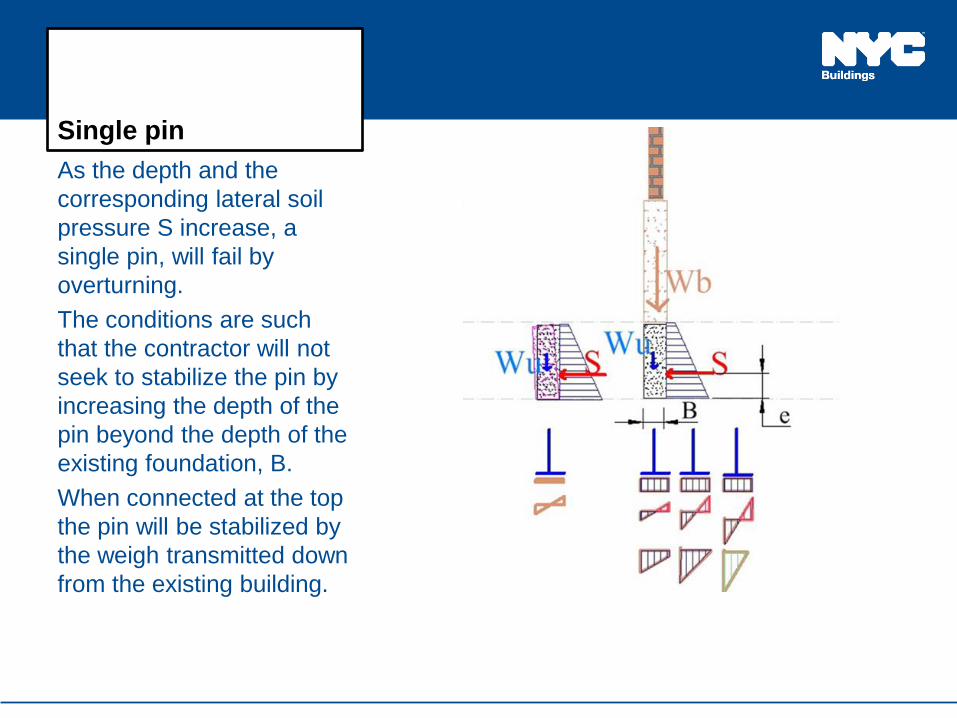
Single pin
As the depth and the
corresponding lateral soil
pressure S increase, a
single pin, will fail by
overturning.
The conditions are such
that the contractor will not
seek to stabilize the pin by
increasing the depth of the
pin beyond the depth of the
existing foundation, B.
When connected at the top
the pin will be stabilized by
the weigh transmitted down
from the existing building.
3/17/2015 DESCH -draft 7

Repeated installation
of a single pin?
In many projects the underpinning
of an entire wall is viewed as a
repeated installation of a single
pin.
Unless based on engineering, the
simultaneous removal of soil and
installation of pins might lead to:
Increase in the vertical
pressure exerted on the
underlying soil, sometimes
beyond allowable values.
Effects of the lateral soil
pressure will additionally
increase the vertical pressure
on the underlying soil.
The soil lateral pressure will
affect locally the existing
building.
3/17/2015 DESCH -draft 8

Underpinning as
support of excavation
The “repeated one pin” approach might misses considering the larger effect on the entire wall or building produced by the installation of a “support of excavation” system.
The sketch shows clearly that at some point in the execution process a support of excavation system is in place.
Lateral loads exerted on this support system will induce forces in the existing building wall above and in the foundation bellow.
3/17/2015 DESCH -draft 9

Steps for designing a pin underpining
A. Determine soil bearing capacity and other properties.
B. Existing Building (to be underpinned)
a) Determine condition of existing building
b) Determine potential response of existing building
C. Determine vertical loads on existing foundation
D. Evaluate dimension of pin (for each phase).
E. Determine the structural model of the underpinned structure that satisfies the known building and soil conditions.
F. Verify strength, sliding and overturning for each element at each phase, including soil carrying capacity.
3/17/2015 DESCH -draft 10
A. Soil properties and capacity
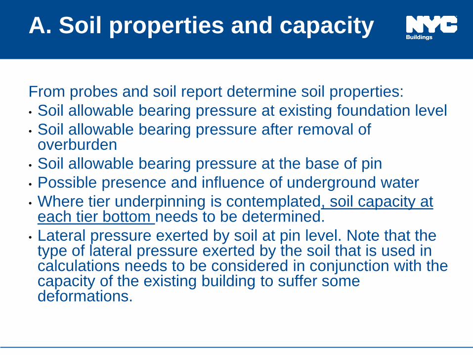
From probes and soil report determine soil properties:
• Soil allowable bearing pressure at existing foundation level
• Soil allowable bearing pressure after removal of overburden
• Soil allowable bearing pressure at the base of pin
• Possible presence and influence of underground water
• Where tier underpinning is contemplated, soil capacity at each tier bottom needs to be determined.
• Lateral pressure exerted by soil at pin level. Note that the type of lateral pressure exerted by the soil that is used in calculations needs to be considered in conjunction with the capacity of the existing building to suffer some deformations.
3/17/2015 DESCH -draft 11

Active vs At Rest Soil Pressure
• One needs to be aware that the active soil pressure is a lower boundary of the soil lateral pressure ( that is, higher lateral pressures might develop). These values can be used assuming that some rotation or displacement may take place ( that is, the wall system has some flexibility)
• In some particular cases, some minor rotation or displacement might be accommodated (elastically?) by the building/foundation/pin system. These minor movements could be sufficient to lower the lateral pressure to active pressure values.
• When the system is fragile and/or no movement is acceptable, the calculations need to use at rest pressure. For instance rubble walls, especially those in poor conditions, should be considered having no flexibility.
3/17/2015 DESCH -draft 12

B. Existing Buildings
The structural configuration of the building to be underpinned plays an essential role in the design of the underpinning.
The majority of the underpinning problems occur during underpinning of load bearing unreinforced masonry buildings. These older buildings have never been explicitly designed to sustain horizontal loads. When horizontal (lateral) loads are applied perpendicular to the face of a masonry wall ( out of plane loads), the wall’s response is weak. Pin underpinning has the potential to introduce such out of plane loads.
Understanding the potential response of the underpinned building to lateral load is now a specific code requirement.
3/17/2015 DESCH -draft 13

Condition Assessment
of Existing Buildings
Building lean
Wall cracks
Wood deterioration
Evidence of
foundation settlement
Eroded mortar joints
3/17/2015 DESCH -draft 14

Vertical cracks at
corner
Cracks at corner
indicate serious
problems with general
building stability and
load paths to shear
walls.
Some corner ties
installations are not
always effective.
• .
3/17/2015 DESCH -draft 15

Wall leaning outward
The weight of the wall itself
increases the walls’
tendency of the rotate. The
capacity of the load path to
transfer to shear walls the
forces induced by the lean
may be at its limit.
One of the probable causes
of the lean is poor condition
of foundation. This will be
further destabilized by
underpinning.
The lean of the building can
increase and reach collapse
even under only service
loads. 3/17/2015 DESCH -draft 16

Elements Influencing
Stability and Load
Path
Floor to floor height vs.
wall thickness
Floor and joists
anchorage to walls
Wall to wall anchorage
Interior walls
Number of floors
3/17/2015 DESCH -draft 17

Existing building
3/17/2015 DESCH -draft 18
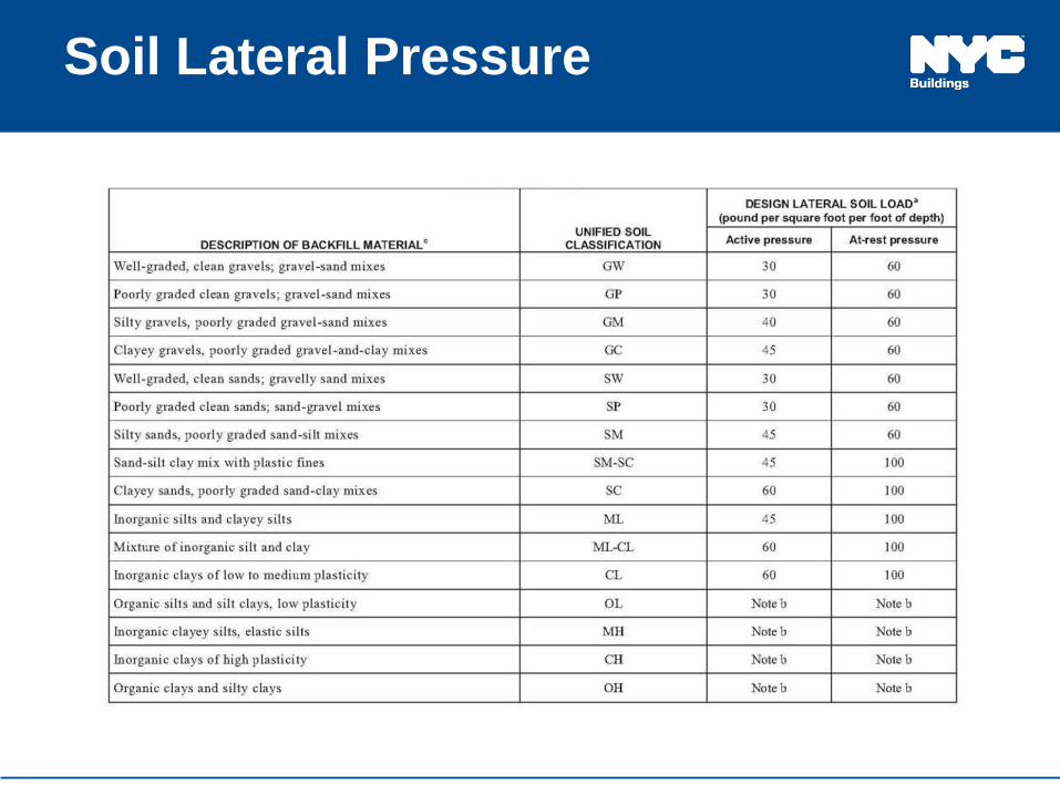
Soil Lateral Pressure
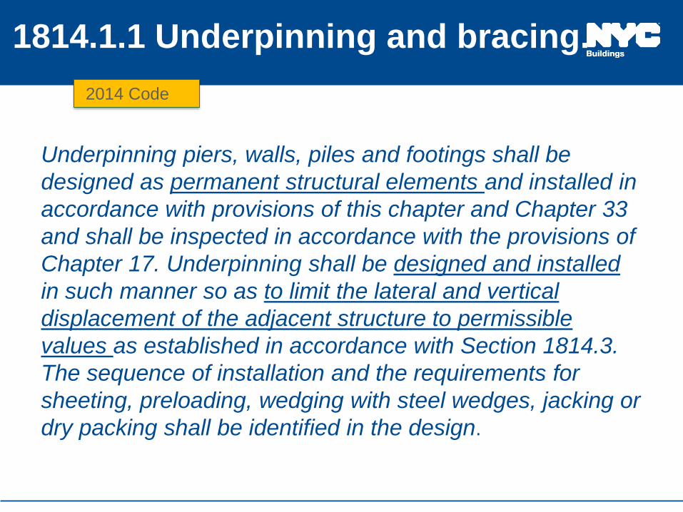
1814.1.1 Underpinning and bracing.
Underpinning piers, walls, piles and footings shall be
designed as permanent structural elements and installed in
accordance with provisions of this chapter and Chapter 33
and shall be inspected in accordance with the provisions of
Chapter 17. Underpinning shall be designed and installed
in such manner so as to limit the lateral and vertical
displacement of the adjacent structure to permissible
values as established in accordance with Section 1814.3.
The sequence of installation and the requirements for
sheeting, preloading, wedging with steel wedges, jacking or
dry packing shall be identified in the design.
3/17/2015 DESCH -draft 20
2014 Code

1814.1.1 Underpinning and bracing (cntd)
The design shall take in account the effects on foundation
and structure produced by the lateral earth pressure
exerted on the underpinning. Lateral support for
underpinning, if needed, shall be accounted for during the
design of the new construction. The design and
construction sequence of temporary lateral supports used
prior to the installation of the foundation walls shall be
included on the design drawings.
3/17/2015 DESCH -draft 21

Change in forces and stresses?
The original intent of some better masonry
builders was to keep the floor diaphragm in
compression. Soil pressure on foundation walls
as well some inclination of the foundation bottom
contributed to this. When in compression, the
capacity of the wall to joist tie is less important.
Underpinning might change the general
distribution of forces. The lateral soil pressures
might not balance. In the new condition the
capacity of the diaphragm to wall connection
becomes important. It is essential to prevent the
raking of the building.
3/17/2015 DESCH -draft 22

C. Determine vertical loads
There is only slight difference between present code and
older codes in terms of live and dead load.
Determine pressure at base of brick
Determine pressure at base of rubble wall foundation in
existing condition.
Account for eccentric loads ( especially due to building
leans).
3/17/2015 DESCH -draft 23

D. Evaluate pin dimensions
The pin dimensions are governed by the capacity of the
foundation above to span ( in undisturbed condition).
The number of simultaneous pin instillations shall
consider the need to keep within allowable values the
pressure on underlying soil. ( at each step of the
sequenced operation).
The capacity to operate safely from the approach pit.
The size of the pin is many times limited by site/shape
new building considerations. ( Is this acceptable?)
3/17/2015 DESCH -draft 24
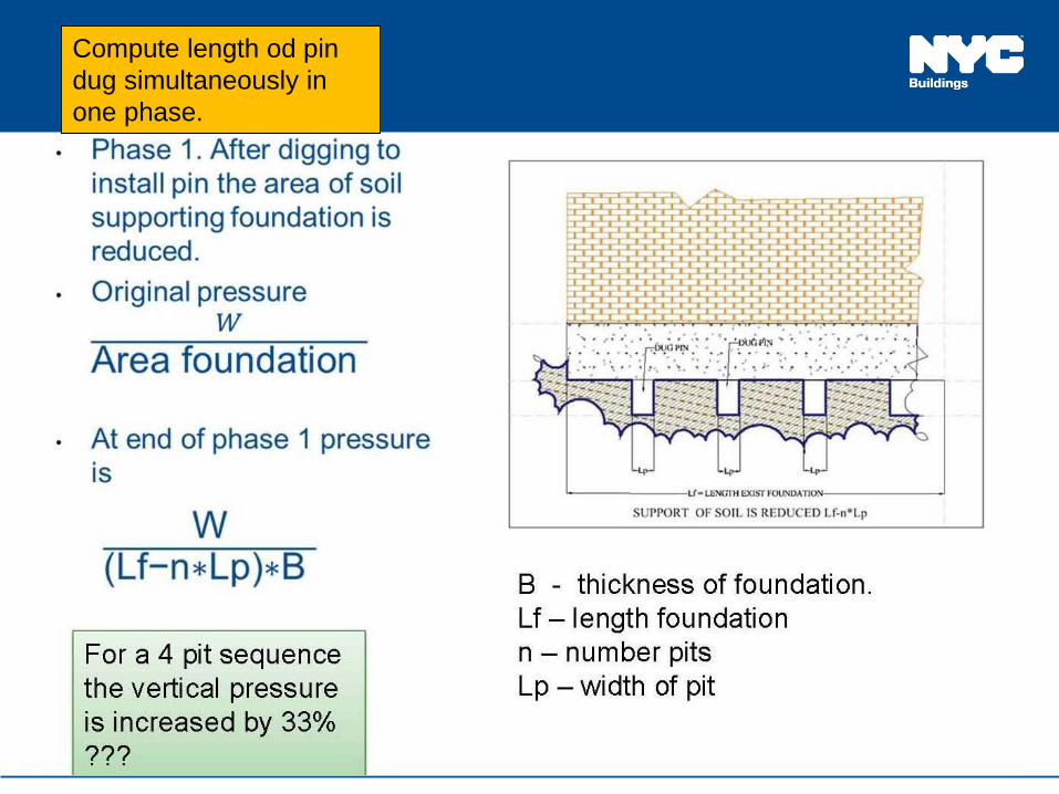
Compute length od pin
dug simultaneously in
one phase.

Compute
Width/Length of Pin

E. MODELLING THE UNDERPINNED
STRUCTURE
The designer needs to determine a structural model that
satisfies the soil bearing capacity and the capacity of the
existing structure to carry the newly imposed loads.
If for whatever reason ( e.g. lack of access, lack of
probes, etc.) a condition is not positively known, the most
detrimental case should be considered.
If the existing structure is not capable to carry newly
imposed loads, these loads shall be carried by special
installations ( e.g. anchors, braces) or solutions other
than pin underpinning need to be considered.
3/17/2015 DESCH -draft 27

E. MODELLING THE UNDERPINNED
STRUCTURE
W W W
S S S
IN ALL CASES THE SOIL SHALL BE
ABLE TO SAFELY CARRY THE
APPLIED VERTICAL LOAD W
STRUCTURE DOES NOT
PARTICIPATE IN
RESISITING FORCE “S “
WITHOUT SUPPORT FROM THE
BUILDING THE EFFECTS OF FORCE
“S” OVERWHELM SOIL CAPACITY 3/17/2015 DESCH -draft 28

CASE A
As long as the soil can
safely resist all loads
and the system pin &
wall do not overturn, the
lateral loads transmitted
to the building are
minimal as the system
could work as a
retaining wall
(without top support.)
No lateral support
provided by the
building
3/17/2015 DESCH -draft 29
Improper shimming
might introduce moment

CASE A
The entire effect of soil lateral
pressure is taken by base of
underpin.
The building on top does not
support any portion of the
soil lateral load
It acts as a cantilever,
restrained at the base (or as
retaining wall.)
Depending on the size of the
various loads and geometry
one of the three possible
pressure on soil conditions
might occur
3/17/2015 DESCH -draft 30

CASE A.
The pressure exerted by the
pin base on the soil is the
resultant of the combination of
vertical forces and moment
due to the soil lateral
pressure.
A special case is when the
calculated tensile stresses
are larger than the
compression due to the
vertical forces (see model
calculation) .
When Pnt exceeds soil
bearing values CASE A model
cannot be used.
3/17/2015 DESCH -draft 31

The loads applied to the
soil underlying the pin
create an overstress
condition. In the absence of
additional lateral support
the system will move. The
floor diaphragm (or any
other load resisting system)
needs to absorb some
loads.
3/17/2015 DESCH -draft 32
CASE B

CASE B
The loads applied to the
soil underlying the pin
create an overstress
condition. In the absence of
additional lateral support
the system will move. The
floor diaphragm (or any
other load resisting system)
needs to absorb some
loads.
3/17/2015 DESCH -draft 33
NOTE – one needs to
verify the interface –
pin/existing foundation for
moment transmission
capacity

CASE B-1
In the loads transmitted to
the diaphragm are those
that limit the stresses at the
base of the underpin to
within safe values.
CASE B-2
In the soil does not have
reserve of bearing capacity
and no moment restraint is
present. The model a simply
supported beam/column.
3/17/2015 DESCH -draft 34

CASE B
The anchorage wall –
diaphragm needs to
be capable of
receiving and
transferring the loads.
Each element in the
load path needs to be
verified for stresses
and limit of
movement.
The ensemble wall +
foundation + pin form
a column that needs
to be verified.
3/17/2015 DESCH -draft 35

Floor support
When the system is capable of
transferring out of wall plane
loads to the diaphragm (or
other system), the stresses
exerted on the soil at the base
of pin are reduced.
For all cases, the system brick
masonry, rubble foundation
and underpin needs to be
verified as a column under
vertical and lateral forces. The
height of the column shall be
considered from the soil to the
first wall diaphragm connection.
3/17/2015 DESCH -draft 36

CASE B-1
U/P DIAPHRAGM
ANCHORED AT 1ST
FLOOR
Anchorage at 1st floor is
rare.
In some cases friction
between the first floor and
foundation might provide
some support.
3/17/2015 DESCH -draft 37

CASE B-1
U/P DIAPHRAGM
ANCHORED 2ND
FLOOR
Usually the wood floor ( soft
diaphragm) has some
anchorage at the second
floor.
One needs to consider that
the joists embedded in
masonry pockets might be
rotted.
For calculations of
unbraced length and
corresponding ratios one
needs to consider the
thickness of each
component material.
3/17/2015 DESCH -draft 38

MSJC Slenderness Ratios
Type Max l/t or h/t
Bearing Wall 20
Solid or Grouted 18
Exterior Non Bearing 18
Interior Non Bearing 36
t= masonry thickness
h= unsupported height
l= horizontal distance transverse walls

MSJC – Empirical Design
Note that following the example of the MSJC
(TMS 402/ACI 530/ASCE 5), the empirical
design of masonry is becoming severely
limited.

Case B-2
The soil underlying the
underpin can carry only
vertical loads. The base
is acting as a pinned
support. Similarly the
attachment to existing
structure.
This model brings the
largest loads to the
structure and largest
moments in the
pin/foundation/pin
structure. This structure
acts as a column subjected
to moments.
3/17/2015 DESCH -draft 41

Provide Support!
When you cannot
ascertain capacity of
structure to carry lateral
load
PROVIDE SUPPORT!
3/17/2015 DESCH -draft 42

BRACE AND
DEADMAN ISSUES
Dead man needs to be
sized to avoid any
movement
Placement of
deadman needs to
take in account further
excavations.
The deadman also
needs to be checked
for overturn.
Connection pin-brace
needs to be capable to
transfer vertical force. 3/17/2015 DESCH -draft 43

2 TIER U/P
BRACE @ TOP PIN
System prevents transfer
of significant out of plane
forces to existing
masonry ( brick and
rubble wall).
The difficulty of this
installation is finding a
place for the deadman
that will not be disturbed
by subsequent
excavations. The
deadman needs to be
installed prior to digging
for the second tier pins. 3/17/2015 DESCH -draft 44

BRACE 2ND TIER PIN
Bracing of the second tier pin
will introduce out of plane
outward loads on the existing
wall
The unbraced length of the wall
& foundation & pin is the largest
of all the schemes. Similarly the
shear at the pin interface is
larger.
3/17/2015 DESCH -draft 45
In many cases this scheme introduces a large moment at the base of the
existing foundation ( but probably less demanding as this foundation now is
now supported by a pin)

Tie Anchors
The installation of a tie
anchor introduces loads that
need to be considered in
detail.
The vertical load can be
substantial and will increase
the pressure on the soil. Also
it might weaken any
shimming ( already installed).
The horizontal loads shall not
negatively influence the base
of the existing foundation
3/17/2015 DESCH -draft 46

Transfer lateral pressure to support
points
47
The lateral forces exerted
on the pins that are not
supported, need to be
transferred to the brace
(or anchor) via reinforcing
and /or shear keys. 3/17/2015 DESCH -draft

1704.20.1.1 Construction operations
influencing adjacent structures.
Where construction operations have the potential to affect
structurally the condition or occupancy of the subject
structure and/or an adjacent structure, the structural
stability of the such structures shall be subject to special
inspections in accordance with Sections 1704.20.6 through
1704.20.10.
3/17/2015 DESCH -draft 48

1704.20.7.1 Monitoring.
The design documents shall include any requirements for
monitoring of the subject structure and/or adjacent
structures, as determined by the registered design
professional responsible for the design. The monitoring
plan shall be specific to the buildings to be monitored and
operations to be undertaken, and shall specify the scope
and frequency of monitoring, acceptable tolerances, and
reporting criteria for when tolerances are exceeded.
3/17/2015 DESCH -draft 49

Specific to the building
Inspect building
Determine condition
Determine weak elements
Potential of distress due to movement or vibration
3/17/2015 DESCH -draft 50

Protocol of Actions
The monitoring program shall include necessary actions
to address exceedence of pre-established thresholds..
Whom to communicate
Adjust construction ops
Reevaluate construction ops
3/17/2015 DESCH -draft 51
Conclusions
a) The engineer needs to understand the building being
underpinned.
b) There should be calculations for every step of the
underpinning operations.
c) The 2014 code provides more specific requirements
• It requires all designs and monitoring to be specific to the
buildings being underpinned
• It requires an analysis of the existing building for the lateral forces
developed during the underpinning


