
GRUNDFOS DATA BOOKLET
UPZCSingle- and multiple-zone controls for zone pumps and zone valves60 Hz

Ta
ble
of c
on
ten
ts
2
UPZC
1. General description 3
2. Special features 3Additional features, UPZCP-3, -4, -6 3Additional features, UPZCV-3, -4, -6 4
3. Applications 4
4. Identification 4Nameplate 4Production code 4
5. Product range 4
6. Operation 5LED diagnostics 5DIP-switch settings 6
7. Installation 7Mechanical installation 7Electrical installation 7Wiring guidelines 7Wiring diagrams, pump controllers 9Wiring diagrams, zone valve controllers 18
8. Technical data 30
9. Approvals 31
10. Service 31Service parts 31
11. Further product documentation 32
Ge
ne
ral
de
sc
rip
tio
n
UPZC 1
1. General description
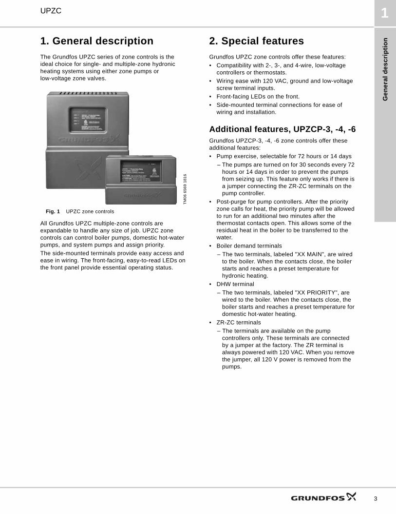
The Grundfos UPZC series of zone controls is the ideal choice for single- and multiple-zone hydronic heating systems using either zone pumps or low-voltage zone valves.
Fig. 1 UPZC zone controls
All Grundfos UPZC multiple-zone controls are expandable to handle any size of job. UPZC zone controls can control boiler pumps, domestic hot-water pumps, and system pumps and assign priority.
The side-mounted terminals provide easy access and ease in wiring. The front-facing, easy-to-read LEDs on the front panel provide essential operating status.
2. Special features
Grundfos UPZC zone controls offer these features:
• Compatibility with 2-, 3-, and 4-wire, low-voltage controllers or thermostats.
• Wiring ease with 120 VAC, ground and low-voltage screw terminal inputs.
• Front-facing LEDs on the front.
• Side-mounted terminal connections for ease of wiring and installation.
Additional features, UPZCP-3, -4, -6Grundfos UPZCP-3, -4, -6 zone controls offer these additional features:
• Pump exercise, selectable for 72 hours or 14 days
– The pumps are turned on for 30 seconds every 72 hours or 14 days in order to prevent the pumps from seizing up. This feature only works if there is a jumper connecting the ZR-ZC terminals on the pump controller.
• Post-purge for pump controllers. After the priority zone calls for heat, the priority pump will be allowed to run for an additional two minutes after the thermostat contacts open. This allows some of the residual heat in the boiler to be transferred to the water.
• Boiler demand terminals
– The two terminals, labeled "XX MAIN", are wired to the boiler. When the contacts close, the boiler starts and reaches a preset temperature for hydronic heating.
• DHW terminal
– The two terminals, labeled "XX PRIORITY", are wired to the boiler. When the contacts close, the boiler starts and reaches a preset temperature for domestic hot-water heating.
• ZR-ZC terminals
– The terminals are available on the pump controllers only. These terminals are connected by a jumper at the factory. The ZR terminal is always powered with 120 VAC. When you remove the jumper, all 120 V power is removed from the pumps.
TM
06
65
69
18
16
3
Ap
plic
atio
ns
UPZC3
4
Additional features, UPZCV-3, -4, -6Grundfos UPZCV-3, -4, -6 zone controls offer these additional features:
• Low-voltage, end-switch output terminals for the zone valves
• Replaceable, snap-fit 40 VA transformer for the zone valve controllers only
• Zone priority with selectable time-out feature
• Pump exercise, selectable for 72 hours or 14 days
– The pumps are turned on for 30 seconds every 72 hours or 14 days in order to prevent the pumps from seizing up.
• Boiler demand terminals
– The two terminals, labeled "XX MAIN", are wired to the boiler. When the contacts close, the boiler starts and reaches a preset temperature for hydronic heating.
• DHW terminal
– The two terminals, labeled "XX PRIORITY", are wired to the boiler. When the contacts close, the boiler starts and reaches a preset temperature for domestic hot-water heating.
3. Applications
Grundfos UPZC zone controls are for single- and multiple-zone, domestic, hydronic heating systems:
UPZCP-1
• For single-zone pump control.
UPZCP-3, -4, -6
• For multiple-zone pump control.
UPZCV-3, -4, -6
• For multiple-zone valve control.
4. Identification
NameplateThe nameplate on the front of the product shows the model, part number, and required electrical input.
The power indicator light and LEDs are located on the nameplate.
See figures 2, 3, and 4.
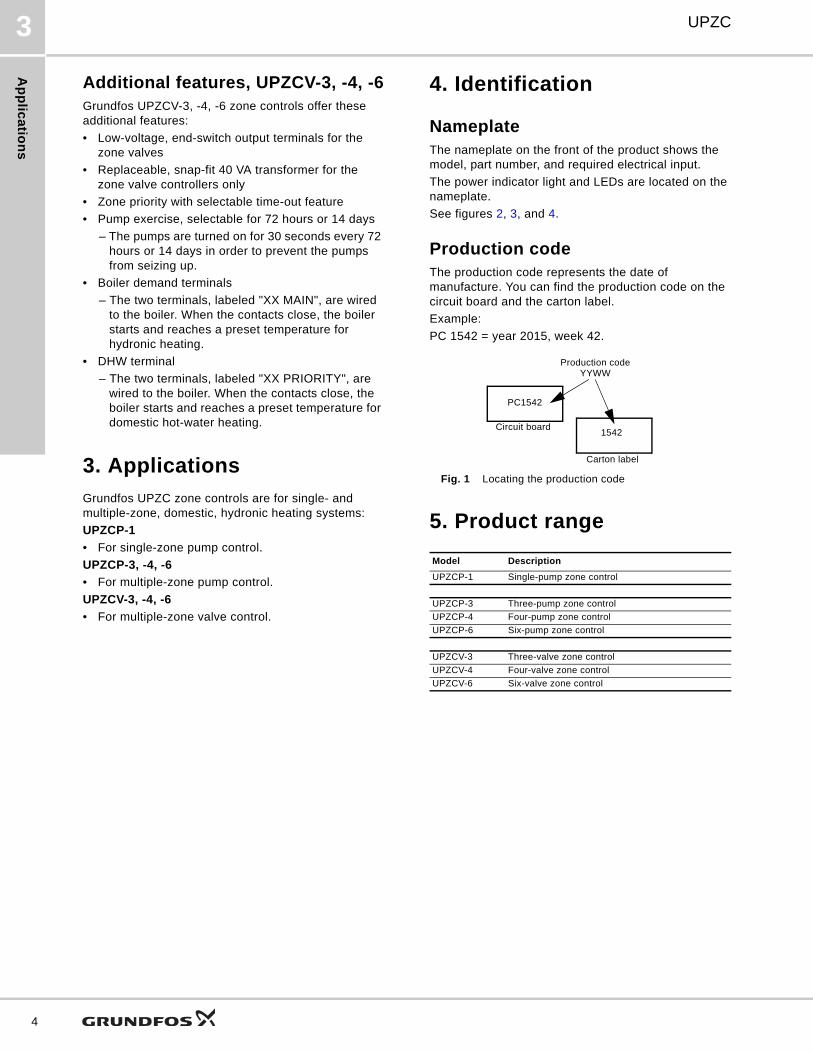
Production codeThe production code represents the date of manufacture. You can find the production code on the circuit board and the carton label.
Example:
PC 1542 = year 2015, week 42.
Fig. 1 Locating the production code
5. Product range
Model Description
UPZCP-1 Single-pump zone control
UPZCP-3 Three-pump zone control
UPZCP-4 Four-pump zone control
UPZCP-6 Six-pump zone control
UPZCV-3 Three-valve zone control
UPZCV-4 Four-valve zone control
UPZCV-6 Six-valve zone control
Production code YYWW
PC1542
1542Circuit board
Carton label
Op
era
tio
n
UPZC 6
6. Operation
LED diagnostics
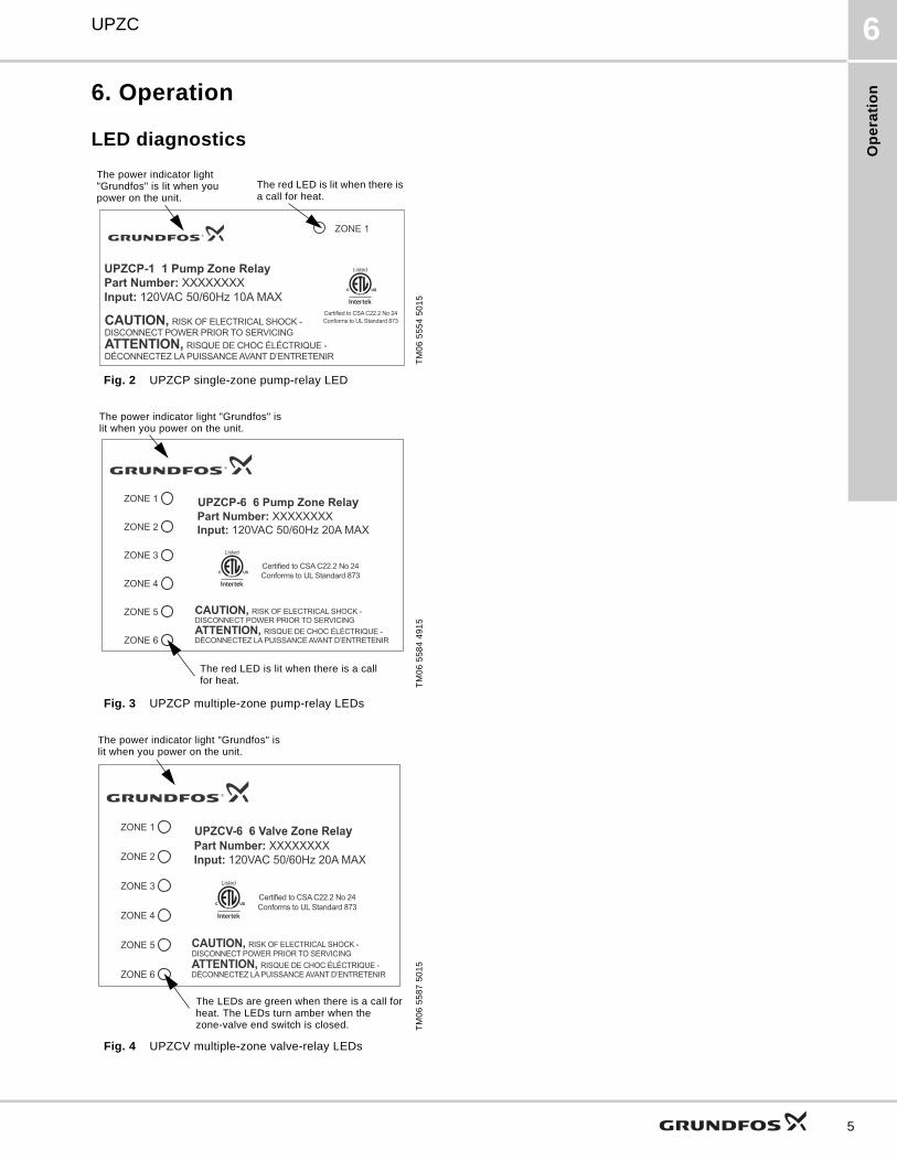
Fig. 2 UPZCP single-zone pump-relay LED
Fig. 3 UPZCP multiple-zone pump-relay LEDs
Fig. 4 UPZCV multiple-zone valve-relay LEDs
TM
06
55
54
50
15
TM
06
55
84
49
15
TM
06
55
87
50
15
UPZCP-1 1 Pump Zone Relay
Part Number: XXXXXXXXInput: 120VAC 50/60Hz 10A MAX
CAUTION, RISK OF ELECTRICAL SHOCK -DISCONNECT POWER PRIOR TO SERVICINGATTENTION, RISQUE DE CHOC ÉLÉCTRIQUE -DÉCONNECTEZ LA PUISSANCE AVANT D’ENTRETENIR
ZONE 1
Certified to CSA C22.2 No 24Conforms to UL Standard 873
Listed
The power indicator light "Grundfos" is lit when you power on the unit.
The red LED is lit when there is a call for heat.
UPZCP-6 6 Pump Zone RelayPart Number: XXXXXXXXInput: 120VAC 50/60Hz 20A MAX
CAUTION, RISK OF ELECTRICAL SHOCK -DISCONNECT POWER PRIOR TO SERVICINGATTENTION, RISQUE DE CHOC ÉLÉCTRIQUE -DÉCONNECTEZ LA PUISSANCE AVANT D’ENTRETENIR
ZONE 1
ZONE 2
ZONE 3
ZONE 4
ZONE 5
ZONE 6
Certified to CSA C22.2 No 24Conforms to UL Standard 873
Listed
The power indicator light "Grundfos" is lit when you power on the unit.
The red LED is lit when there is a call for heat.
UPZCV-6 6 Valve Zone RelayPart Number: XXXXXXXXInput: 120VAC 50/60Hz 20A MAX
CAUTION, RISK OF ELECTRICAL SHOCK -DISCONNECT POWER PRIOR TO SERVICINGATTENTION, RISQUE DE CHOC ÉLÉCTRIQUE -DÉCONNECTEZ LA PUISSANCE AVANT D’ENTRETENIR
ZONE 1
ZONE 2
ZONE 3
ZONE 4
ZONE 5
ZONE 6
Certified to CSA C22.2 No 24Conforms to UL Standard 873
Listed
The LEDs are green when there is a call for heat. The LEDs turn amber when the zone-valve end switch is closed.
The power indicator light "Grundfos" is lit when you power on the unit.
5
Op
era
tion
UPZC6
6
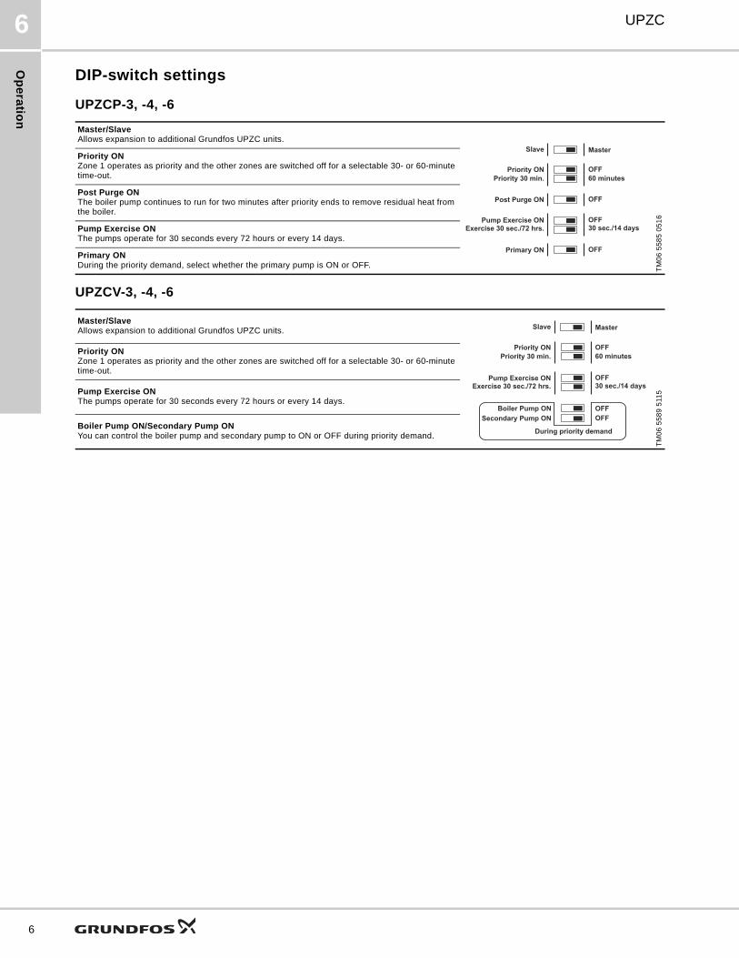
DIP-switch settings
UPZCP-3, -4, -6
UPZCV-3, -4, -6
Master/SlaveAllows expansion to additional Grundfos UPZC units.
TM
06
55
85
05
16
Priority ONZone 1 operates as priority and the other zones are switched off for a selectable 30- or 60-minute time-out.
Post Purge ONThe boiler pump continues to run for two minutes after priority ends to remove residual heat from the boiler.
Pump Exercise ONThe pumps operate for 30 seconds every 72 hours or every 14 days.
Primary ONDuring the priority demand, select whether the primary pump is ON or OFF.
OFFPost Purge ON
OFFPrimary ON
OFF
Priority 30 min.
Priority ON
60 minutes
Pump Exercise ON OFF
Exercise 30 sec./72 hrs. 30 sec./14 days
MasterSlave
Master/SlaveAllows expansion to additional Grundfos UPZC units.
TM
06
55
89
511
5
Priority ONZone 1 operates as priority and the other zones are switched off for a selectable 30- or 60-minute time-out.
Pump Exercise ONThe pumps operate for 30 seconds every 72 hours or every 14 days.
Boiler Pump ON/Secondary Pump ONYou can control the boiler pump and secondary pump to ON or OFF during priority demand.
OFF
OFF
OFF
OFF
Master
Pump Exercise ON
Priority 30 min.
Slave
Priority ON
Exercise 30 sec./72 hrs.
During priority demand
Secondary Pump ON
Boiler Pump ON
60 minutes
30 sec./14 days

Ins
tall
ati
on
UPZC 7
7. Installation
Mechanical installation
Installing the base plateThe base plate must be firmly attached to the wall surface with four screws and anchors using the key holes provided.
Fig. 5 Attach the base plate to the wall with screws and anchors
Electrical installationAll electrical connections must be made using copper wire only.
We recommend that you use these AWG wire sizes:
• 12-16 AWG wire for 120 VAC connections.
• 12-22 AWG wire for thermostat connections.
• 12-22 AWG wire for 24 VAC connections.
Use approved UL conduit fittings.
Additional wiring schematics, specs, and troubleshooting help is available online at www.grundfos.us/controls.
Wiring guidelinesAlso see sections Wiring diagrams, pump controllers on page 9 and Wiring diagrams, zone valve controllers on page 18.
Wiring for thermostats
Fig. 6 Example of thermostat wiring
Wiring for valves, UPZCV-3, -4, -6
Fig. 7 Example of wiring for zone valves
TM
06
55
97
50
15
TM
06
56
07
50
15
Base plate UPZCP-1
Base plate UPZCP-3, -4, -6
and UPZCV-3, -4, -6
TM
06
53
38
511
5T
M0
6 5
33
8 5
115
R
W
C
R
W
C
R
W
C
R
W
C
R
W
C
R Rh W C
Jumper
Aquastat
2-wirethermostat
3-wirethermostat
4-wirethermostat
4
3
2
1
4
3
2
1
4
3
2
1
4
3
2
1
4
3
2
1
4
3
2
1
312
Jumper
Jumper
2-wire zone valve
TACO 570 3-wire zone valve
4-wire zone valve
1 and 2: Motor terminals3 and 4: End-switch terminals
7

Ins
talla
tion
UPZC7
8
Wiring for pumps, UPZCP-3, -4, -6
Fig. 8 Example of wiring for pumps
Wiring for two or more boards, expansion
Fig. 9 Example of wiring for expansion controllers
Wiring for two or more controllers
See fig. 9 for example.
When connecting two or more controllers:
• You can only use the master controller with priority.
• When priority calls, the master board will produce 5 VDC between terminals B and C. This tells the slave board to turn off any zones that are calling for heat. This will also close the contacts "XX PRIORITY".
• When there is a demand for heat, the slave board will produce 5 VDC between terminals A and C. This tells the master board to activate any boiler or secondary pumps and close the contacts "XX MAIN".
• You can connect the pump and valve boards.
• When the slave board calls for heat, the secondary pump will be powered. If a boiler pump and secondary pump are to be used, they must be connected to the same terminals.
• You can use the low voltage wire to connect ABC terminals.
• The 120 VAC power supply must be connected to each board.
• The L and N terminals must be connected the same way on each board. If switched, a differential of 240 VAC can occur resulting in damage to the equipment.
TM
06
56
05
50
15
TM
06
56
06
50
15
L
N
L
N
L
N
L
N
L
N
L
N
L
N
L
N
Groundscrews onbase plate
C
B
A
C
B
A
MasterSlave
MasterSlave
EXPANSION
EXPANSION
Masterboard
Slaveboard
Ins
tall
ati
on
UPZC 7
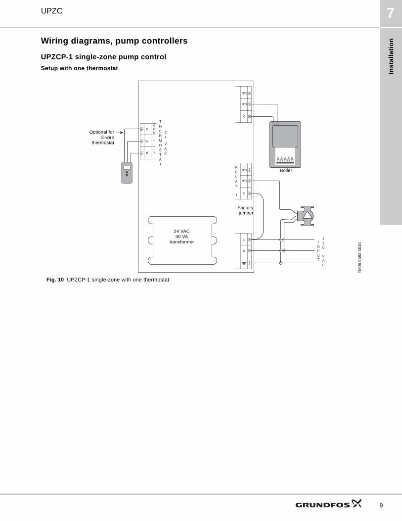
Wiring diagrams, pump controllers
UPZCP-1 single-zone pump control
Setup with one thermostat
Fig. 10 UPZCP-1 single-zone with one thermostat
TM
06
55
93
50
15
R
W
C
T
T
COM
N/C
N/O
C
N/C
N/O
C
L
N
INPUT
120
VAC
24 VAC40 VA
transformer
Boiler
Optional for3-wire
thermostat
Factoryjumper
9
Ins
talla
tion
UPZC7
10
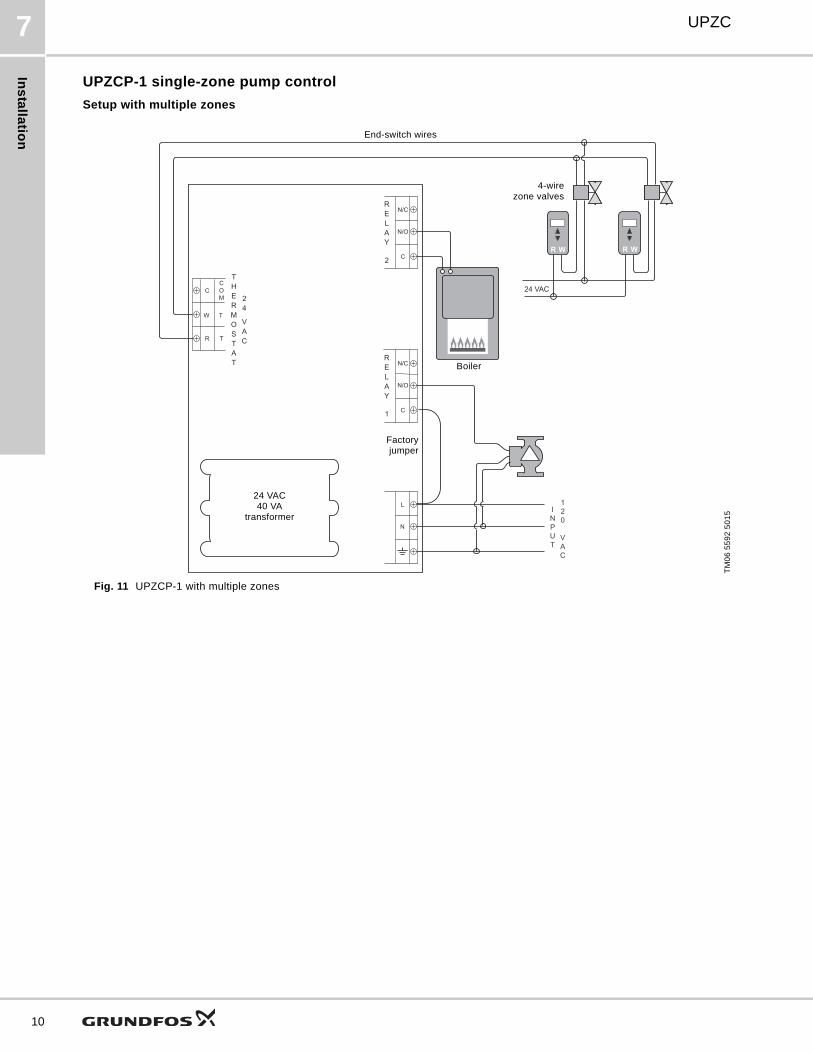
UPZCP-1 single-zone pump control
Setup with multiple zones
Fig. 11 UPZCP-1 with multiple zones
TM
06
55
92
50
15
N/C
N/O
C
N/C
N/O
C
L
N
24 VAC
R
W
C
T
T
COM
R W
INPUT
120
VAC
WR
Factoryjumper
24 VAC40 VA
transformer
Boiler
End-switch wires
4-wirezone valves
Ins
tall
ati
on
UPZC 7
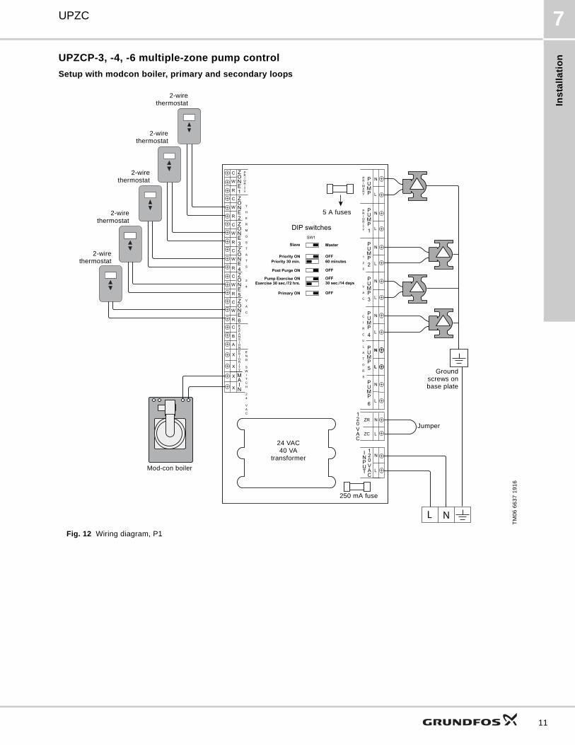
UPZCP-3, -4, -6 multiple-zone pump control
Setup with modcon boiler, primary and secondary loops
Fig. 12 Wiring diagram, P1
TM
06
66
37
19
16
L
N
L
N
ZC
ZR
L
N
C
B
A
X
X
X
X
R
W
C
R
W
C
R
W
C
R
W
C
R
W
C
R
W
C
L N
L
N
L
N
L
N
L
N
L
N
L
N
L
N
OFF
OFF
Master
SW1
Post Purge ON
Priority 30 min.
Slave
Priority ON
Pump Exercise ON
60 minutes
OFF
Exercise 30 sec./72 hrs. 30 sec./14 days
OFFPrimary ON
DIP switches
Jumper
24 VAC40 VA
transformer
250 mA fuse
Mod-con boiler
2-wirethermostat
Groundscrews onbase plate
2-wirethermostat
2-wirethermostat
2-wirethermostat
2-wirethermostat
5 A fuses
11

Ins
talla
tion
UPZC7
12
UPZCP-3, -4, -6 multiple-zone pump control
Setup with conventional boiler, two-pipe direct return, and indirect DHW
Fig. 13 Wiring diagram, P2
TM
06
66
38
19
16
L
N
L
N
ZC
ZR
L
N
C
B
A
X
X
X
X
R
W
C
R
W
C
R
W
C
R
W
C
R
W
C
R
W
C
L N
L
N
L
N
L
N
L
N
L
N
L
N
L
N
OFF
OFF
Master
SW1
Post Purge ON
Priority 30 min.
Slave
Priority ON
Pump Exercise ON
60 minutes
OFF
Exercise 30 sec./72 hrs. 30 sec./14 days
OFFPrimary ON
DIP switches
Jumper
24 VAC40 VA
transformer
250 mA fuse
Conventional boiler
2-wirethermostat
Groundscrews onbase plate
2-wirethermostat
2-wirethermostat
2-wirethermostat
2-wirethermostat
5 A fuses
Aquastatfor DHW
Ins
tall
ati
on
UPZC 7
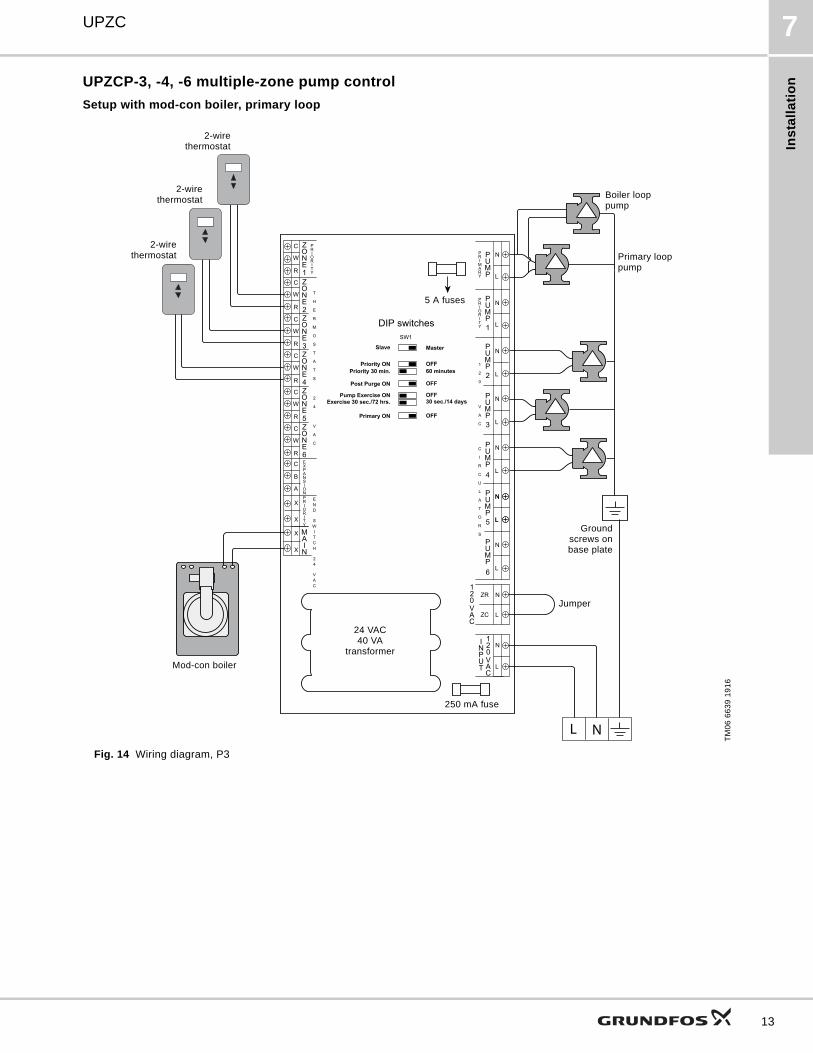
UPZCP-3, -4, -6 multiple-zone pump control
Setup with mod-con boiler, primary loop
Fig. 14 Wiring diagram, P3
TM
06
66
39
19
16
L
N
L
N
ZC
ZR
L
N
C
B
A
X
X
X
X
R
W
C
R
W
C
R
W
C
R
W
C
R
W
C
R
W
C
L N
L
N
L
N
L
N
L
N
L
N
L
N
L
N
OFF
OFF
Master
SW1
Post Purge ON
Priority 30 min.
Slave
Priority ON
Pump Exercise ON
60 minutes
OFF
Exercise 30 sec./72 hrs. 30 sec./14 days
OFFPrimary ON
DIP switches
Jumper
24 VAC40 VA
transformer
250 mA fuse
Mod-con boiler
2-wirethermostat
Groundscrews onbase plate
2-wirethermostat
2-wirethermostat
5 A fuses
Boiler loop pump
Primary loop pump
13
Ins
talla
tion
UPZC7
14
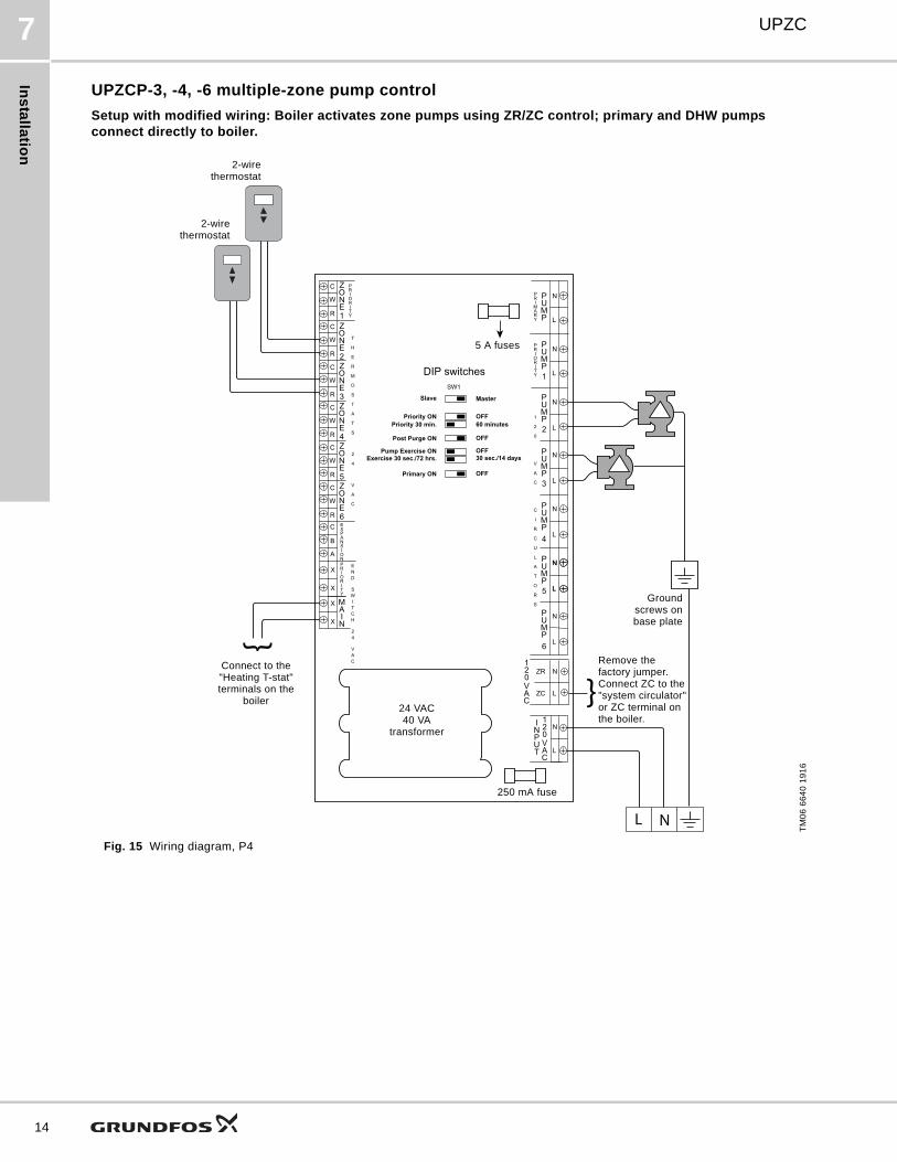
UPZCP-3, -4, -6 multiple-zone pump control
Setup with modified wiring: Boiler activates zone pumps using ZR/ZC control; primary and DHW pumps connect directly to boiler.
Fig. 15 Wiring diagram, P4
TM
06
66
40
19
16
L
N
L
N
ZC
ZR
L
N
C
B
A
X
X
X
X
R
W
C
R
W
C
R
W
C
R
W
C
R
W
C
R
W
C
L N
L
N
L
N
L
N
L
N
L
N
L
N
L
N
OFF
OFF
Master
SW1
Post Purge ON
Priority 30 min.
Slave
Priority ON
Pump Exercise ON
60 minutes
OFF
Exercise 30 sec./72 hrs. 30 sec./14 days
OFFPrimary ON
DIP switches
Remove the factory jumper.Connect ZC to the "system circulator" or ZC terminal on the boiler.
24 VAC40 VA
transformer
250 mA fuse
Connect to the "Heating T-stat" terminals on the
boiler
2-wirethermostat
Groundscrews onbase plate
2-wirethermostat
5 A fuses

Ins
tall
ati
on
UPZC 7
This page intentionally left blank.
15

Ins
talla
tion
UPZC7
16
UPZCP-3, -4, -6 multiple-zone pump control
Setup with mod-con boiler, two-pipe direct return, indirect DHW, two controllers connected, master controller
Fig. 16 Wiring diagram, P5, master.
See fig. 17 for corresponding diagram for slave controller.
TM
06
66
41
19
16
L
N
L
N
ZC
ZR
L
N
X
X
X
X
R
W
C
R
W
C
R
W
C
R
W
C
R
W
C
R
W
C
L N
L
N
L
N
L
N
L
N
L
N
L
N
L
N
OFF
OFF
Master
SW1
Post Purge ON
Priority 30 min.
Slave
Priority ON
Pump Exercise ON
60 minutes
OFF
Exercise 30 sec./72 hrs. 30 sec./14 days
OFFPrimary ON
DIP switches
C
B
A
24 VAC40 VA
transformer
250 mA fuse
2-wirethermostat
Ground screwson base plate
2-wirethermostat
5 A fuses
Jumper
Conventional boiler
Connect to the corresponding A, B, C terminals on the slave controller. See fig. 17.
2-wirethermostat
2-wirethermostat
2-wirethermostat
2-wirethermostat

Ins
tall
ati
on
UPZC 7
UPZCP-3, 4, 6 multiple-zone pump control
Setup with mod-con boiler, two-pipe direct return, indirect DHW, two controllers connected, slave controller
Fig. 17 Wiring diagram, P5, slave controller.
See fig. 16 for corresponding diagram for master controller.
TM
06
66
42
19
16
L
N
L
N
ZC
ZR
L
N
X
X
X
X
R
W
C
R
W
C
R
W
C
R
W
C
R
W
C
R
W
C
L N
L
N
L
N
L
N
L
N
L
N
L
N
L
N
OFF
OFF
Master
SW1
Post Purge ON
Priority 30 min.
Slave
Priority ON
Pump Exercise ON
60 minutes
OFF
Exercise 30 sec./72 hrs. 30 sec./14 days
OFFPrimary ON
DIP switches
C
A
B
Connect to the corresponding A,B, C terminals on master
controller. See fig. 16.
2-wirethermostat
24 VAC40 VA
transformer
250 mA fuse
5 A fuses
Jumper
Ground screwson base plate
17

Ins
talla
tion
UPZC7
18
Wiring diagrams, zone valve controllers
UPZCV-3, -4, -6 multiple-zone valve control
Setup with mod-con boiler, primary and secondary loops
Fig. 18 Wiring diagram, V1
TM
06
66
24
19
16
L
N
L
N
L
N
L
N
C
B
A
X
X
X
X
R
W
C
R
W
C
R
W
C
R
W
C
R
W
C
R
W
C
4
3
2
1
4
3
2
1
4
3
2
1
4
3
2
1
4
3
2
1
4
3
2
1
L N
OFF
OFF
OFF
OFF
Master
SW1
Pump Exercise ON
Priority 30 min.
Slave
Priority ON
Exercise 30 sec./72 hrs.
During priority demand
Secondary Pump ON
Boiler Pump ON
60 minutes
30 sec./14 days
Dip switches
Mod-con boiler
4-wire zone valve
2-wirethermostat
500 mA fuse 500 mA fuse
24 VAC40 VA
transformer
24 VAC40 VA
transformer
Ground screws on frame
2-wirethermostat
2-wirethermostat
2-wirethermostat
2-wirethermostat
2-wirethermostat
4-wire zone valve
4-wire zone valve
4-wire zone valve
4-wire zone valve
4-wire zone valve

Ins
tall
ati
on
UPZC 7
UPZCV-3, -4, -6 multiple-zone valve control
Setup with mod-con boiler, primary and secondary loops, priority, indirect DHW
Fig. 19 Wiring diagram, V2
TM
06
66
25
19
16
L
N
L
N
L
N
L
N
C
B
A
X
X
X
X
R
W
C
R
W
C
R
W
C
R
W
C
R
W
C
R
W
C
4
3
2
1
4
3
2
1
4
3
2
1
4
3
2
1
4
3
2
1
4
3
2
1
L N
OFF
OFF
OFF
OFF
Master
SW1
Pump Exercise ON
Priority 30 min.
Slave
Priority ON
Exercise 30 sec./72 hrs.
During priority demand
Secondary Pump ON
Boiler Pump ON
60 minutes
30 sec./14 days
Dip switches
Mod/con boilerMod-con boiler
4-wire zone valve
2-wirethermostat
500 mA fuse 500 mA fuse
24 VAC40 VA
transformer
24 VAC40 VA
transformer
Ground screws on frame
2-wirethermostat
2-wirethermostat
2-wirethermostat
2-wirethermostat
Aquastat
4-wire zone valve
4-wire zone valve
4-wire zone valve
4-wire zone valve
Jumper
DHW priority pump
19
Ins
talla
tion
UPZC7
20
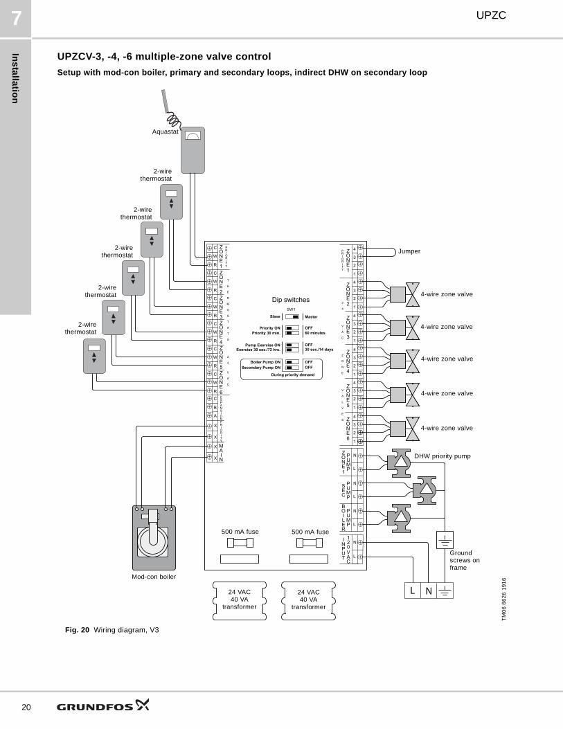
UPZCV-3, -4, -6 multiple-zone valve control
Setup with mod-con boiler, primary and secondary loops, indirect DHW on secondary loop
Fig. 20 Wiring diagram, V3
TM
06
66
26
19
16
L
N
L
N
L
N
L
N
C
B
A
X
X
X
X
R
W
C
R
W
C
R
W
C
R
W
C
R
W
C
R
W
C
4
3
2
1
4
3
2
1
4
3
2
1
4
3
2
1
4
3
2
1
4
3
2
1
L N
OFF
OFF
OFF
OFF
Master
SW1
Pump Exercise ON
Priority 30 min.
Slave
Priority ON
Exercise 30 sec./72 hrs.
During priority demand
Secondary Pump ON
Boiler Pump ON
60 minutes
30 sec./14 days
Dip switches
Mod-con boiler
4-wire zone valve
2-wirethermostat
500 mA fuse 500 mA fuse
24 VAC40 VA
transformer
24 VAC40 VA
transformer
Ground screws on frame
2-wirethermostat
2-wirethermostat
2-wirethermostat
2-wirethermostat
Aquastat
4-wire zone valve
4-wire zone valve
4-wire zone valve
4-wire zone valve
Jumper
DHW priority pump

Ins
tall
ati
on
UPZC 7
This page intentionally left blank.
21

Ins
talla
tion
UPZC7
22
UPZCV-3, -4, -6 multiple-zone valve control
Setup with mod-con boiler, primary and secondary loops, indirect DHW on primary loop, two controllers connected, master controller
Fig. 21 Wiring diagram, V4, master controller.
See fig. 22 for corresponding diagram for slave controller.
TM
06
66
27
19
16
L
N
L
N
L
N
L
N
X
X
X
X
R
W
C
R
W
C
R
W
C
R
W
C
R
W
C
R
W
C
4
3
2
1
4
3
2
1
4
3
2
1
4
3
2
1
4
3
2
1
4
3
2
1
L N
OFF
OFF
OFF
OFF
Master
SW1
Pump Exercise ON
Priority 30 min.
Slave
Priority ON
Exercise 30 sec./72 hrs.
During priority demand
Secondary Pump ON
Boiler Pump ON
60 minutes
30 sec./14 days
Dip switches
C
B
A
Mod-con boiler
4-wire zone valve
2-wirethermostat
500 mA fuse 500 mA fuse
24 VAC40 VA
transformer
24 VAC40 VA
transformer
Ground screws on frame
2-wirethermostat
2-wirethermostat
2-wirethermostat
2-wirethermostat
Aquastat
4-wire zone valve
4-wire zone valve
4-wire zone valve
4-wire zone valve
Connect to the corresponding A, B, C terminals on the slave controller. See fig. 22.
Jumper
DHW priority pump
Ins
tall
ati
on
UPZC 7
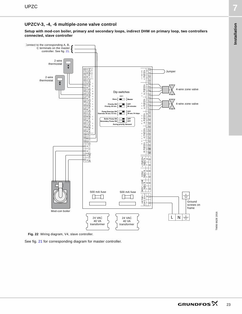
UPZCV-3, -4, -6 multiple-zone valve control
Setup with mod-con boiler, primary and secondary loops, indirect DHW on primary loop, two controllers connected, slave controller
Fig. 22 Wiring diagram, V4, slave controller.
See fig. 21 for corresponding diagram for master controller.
TM
06
66
28
19
16
L
N
L
N
L
N
L
N
X
X
X
X
R
W
C
R
W
C
R
W
C
R
W
C
R
W
C
R
W
C
4
3
2
1
4
3
2
1
4
3
2
1
4
3
2
1
4
3
2
1
4
3
2
1
L N
OFF
OFF
OFF
OFF
Master
SW1
Pump Exercise ON
Priority 30 min.
Slave
Priority ON
Exercise 30 sec./72 hrs.
During priority demand
Secondary Pump ON
Boiler Pump ON
60 minutes
30 sec./14 days
Dip switches
C
B
A
Mod-con boiler
4-wire zone valve
500 mA fuse 500 mA fuse
24 VAC40 VA
transformer
24 VAC40 VA
transformer
Ground screws on frame
2-wirethermostat
2-wirethermostat
4-wire zone valve
Connect to the corresponding A, B,C terminals on the master
controller. See fig. 21.
Jumper
23
Ins
talla
tion
UPZC7
24
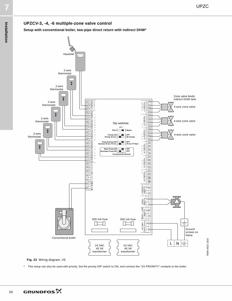
UPZCV-3, -4, -6 multiple-zone valve control
Setup with conventional boiler, two-pipe direct return with indirect DHW*
Fig. 23 Wiring diagram, V5
* This setup can also be used with priority. Set the priority DIP switch to ON, and connect the "XX PRIORITY" contacts to the boiler.
TM
06
66
32
19
16
L
N
L
N
L
N
L
N
C
B
A
X
X
X
X
R
W
C
R
W
C
R
W
C
R
W
C
R
W
C
R
W
C
4
3
2
1
4
3
2
1
4
3
2
1
4
3
2
1
4
3
2
1
4
3
2
1
L N
OFF
OFF
OFF
OFF
Master
SW1
Pump Exercise ON
Priority 30 min.
Slave
Priority ON
Exercise 30 sec./72 hrs.
During priority demand
Secondary Pump ON
Boiler Pump ON
60 minutes
30 sec./14 days
Dip switches
Conventional boiler
4-wire zone valve
2-wirethermostat
500 mA fuse 500 mA fuse
24 VAC40 VA
transformer
24 VAC40 VA
transformer
Ground screws on frame
2-wirethermostat
2-wirethermostat
2-wirethermostat
2-wirethermostat
Aquastat
4-wire zone valve
4-wire zone valve
Zone valve feeds indirect DHW tank.
Ins
tall
ati
on
UPZC 7
This page intentionally left blank.
25

Ins
talla
tion
UPZC7
26
UPZCV-3, -4, -6 multiple-zone valve control
Setup with mod-con boiler, primary and secondary loops, two secondary pumps, two controllers connected, master controller
Fig. 24 Wiring diagram, V6, master controller.
See fig. 25 for corresponding diagram for slave controller.
TM
06
66
33
19
16
L
N
L
N
L
N
L
N
X
X
X
X
R
W
C
R
W
C
R
W
C
R
W
C
R
W
C
R
W
C
4
3
2
1
4
3
2
1
4
3
2
1
4
3
2
1
4
3
2
1
4
3
2
1
L N
OFF
OFF
OFF
OFF
Master
SW1
Pump Exercise ON
Priority 30 min.
Slave
Priority ON
Exercise 30 sec./72 hrs.
During priority demand
Secondary Pump ON
Boiler Pump ON
60 minutes
30 sec./14 days
Dip switches
C
B
A
Mod-con boiler
4-wire zone valve
2-wirethermostat
500 mA fuse 500 mA fuse
24 VAC40 VA
transformer
24 VAC40 VA
transformer
Ground screws on frame
2-wirethermostat
2-wirethermostat
2-wirethermostat
2-wirethermostat
Aquastat
4-wire zone valve
4-wire zone valve
4-wire zone valve
4-wire zone valve
Connect to the corresponding A, B, C terminals on the slave controller. See fig. 25.
4-wire zone valve
Secondary pump 1

Ins
tall
ati
on
UPZC 7
UPZCV-3, -4, -6 multiple-zone valve control
Setup with mod-con boiler, primary and secondary loops, two secondary pumps, two controllers connected, slave controller
Fig. 25 Wiring diagram, V6, slave controller.
See fig. 24 for corresponding diagram for master controller.
TM
06
66
34
19
16
L
N
L
N
L
N
L
N
X
X
X
X
R
W
C
R
W
C
R
W
C
R
W
C
R
W
C
R
W
C
4
3
2
1
4
3
2
1
4
3
2
1
4
3
2
1
4
3
2
1
4
3
2
1
L N
OFF
OFF
OFF
OFF
Master
SW1
Pump Exercise ON
Priority 30 min.
Slave
Priority ON
Exercise 30 sec./72 hrs.
During priority demand
Secondary Pump ON
Boiler Pump ON
60 minutes
30 sec./14 days
Dip switches
C
B
A
Mod-con boiler
4-wire zone valve
500 mA fuse 500 mA fuse
24 VAC40 VA
transformer
24 VAC40 VA
transformer
Ground screws on frame
2-wirethermostat
2-wirethermostat
Connect to the corresponding A, B,C terminals on the master controller.
See fig. 24.
4-wire zone valve
Secondary pump 2
27
Ins
talla
tion
UPZC7
28
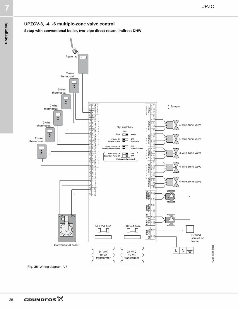
UPZCV-3, -4, -6 multiple-zone valve control
Setup with conventional boiler, two-pipe direct return, indirect DHW
Fig. 26 Wiring diagram, V7
TM
06
66
35
19
16
L
N
L
N
L
N
L
N
C
B
A
X
X
X
X
R
W
C
R
W
C
R
W
C
R
W
C
R
W
C
R
W
C
4
3
2
1
4
3
2
1
4
3
2
1
4
3
2
1
4
3
2
1
4
3
2
1
L N
OFF
OFF
OFF
OFF
Master
SW1
Pump Exercise ON
Priority 30 min.
Slave
Priority ON
Exercise 30 sec./72 hrs.
During priority demand
Secondary Pump ON
Boiler Pump ON
60 minutes
30 sec./14 days
Dip switches
Conventional boiler
4-wire zone valve
2-wirethermostat
500 mA fuse 500 mA fuse
24 VAC40 VA
transformer
24 VAC40 VA
transformer
Ground screws on frame
2-wirethermostat
2-wirethermostat
2-wirethermostat
2-wirethermostat
Aquastat
4-wire zone valve
4-wire zone valve
4-wire zone valve
4-wire zone valve
Jumper
Ins
tall
ati
on
UPZC 7
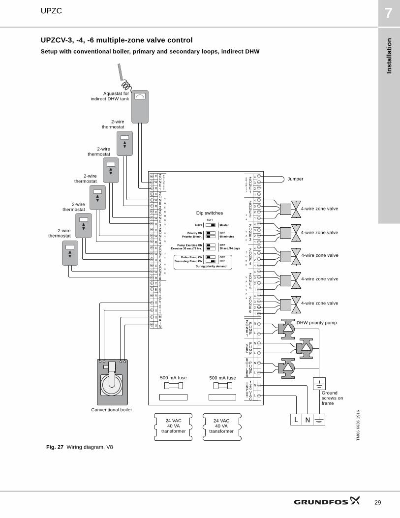
UPZCV-3, -4, -6 multiple-zone valve control
Setup with conventional boiler, primary and secondary loops, indirect DHW
Fig. 27 Wiring diagram, V8
TM
06
66
36
19
16
L
N
L
N
L
N
L
N
C
B
A
X
X
X
X
R
W
C
R
W
C
R
W
C
R
W
C
R
W
C
R
W
C
4
3
2
1
4
3
2
1
4
3
2
1
4
3
2
1
4
3
2
1
4
3
2
1
L N
OFF
OFF
OFF
OFF
Master
SW1
Pump Exercise ON
Priority 30 min.
Slave
Priority ON
Exercise 30 sec./72 hrs.
During priority demand
Secondary Pump ON
Boiler Pump ON
60 minutes
30 sec./14 days
Dip switches
Conventional boiler
4-wire zone valve
2-wirethermostat
500 mA fuse 500 mA fuse
24 VAC40 VA
transformer
24 VAC40 VA
transformer
Ground screws on frame
2-wirethermostat
2-wirethermostat
2-wirethermostat
2-wirethermostat
Aquastat forindirect DHW tank
4-wire zone valve
4-wire zone valve
4-wire zone valve
4-wire zone valve
Jumper
DHW priority pump
29

Te
ch
nic
al d
ata
UPZC8
30
8. Technical data
UPZCP-1 single-zone pump control relay
UPZCP- 3, 4, 6 multiple zone pump control relay
UPZCP-1Single-zone pump control relay
Input power, 60 Hz 120 VAC
Transformer voltage 24 VAC, 40 VA, Class 2
Thermostat output [A] 0.125
Maximum single-phase motor rating, per zone [A] 5
Maximum combined load rating: output @120 VAC [A] 10
Temperature range, storage [°F (°C)] 50-100 (10-38)
Temperature range, maximum operation [°F (°C)] 0-100 (-18 to +38)
Maximum operating humidity range [%] RH 90
Number of knockouts 6
Size of knockouts [in. (mm)] 0.875 (22)
Dimensions, W x H x D [in. (mm)] 5.93 x 4.80 x 2.36 (151 x 122 x 60)
Approvals CSA 22.2 No. 24/UL Standard 873
Relay type Sealed
Cover panel ABS - fire rated
Base plate material Galvanized steel
Terminal block, side-mounted PA66
Front indicator lights LED
Model
UPZCP-3Three-zone pump control relay
UPZCP-4Four-zone pump control relay
UPZCP-6Six-zone pump control relay
Input power, 60 Hz 120 VAC
Transformer voltage 24 VAC, 40 VA, Class 2
Thermostat output [A] 0.375 0.5 0.75
Maximum single-phase motor rating, per zone [A]
5
Maximum combined load rating:output @ 120 VAC [A]
20
Temperature range, storage [°F (°C)] 50-100 (10-38)
Temperature range, maximum operation [°F (°C)]
0-100 (-18 to +38)
Maximum operating humidity range [%] RH 90
Number of knockouts 12
Size of knockouts [in. (mm)] 0.875 (22)
Dimensions, W x H x D [in. (mm)] 8.15 x 10.67 x 2.72 (208 x 272 x 70)
Approvals CSA 22.2 No. 24/UL Standard 873
Relay type Sealed
Cover panel ABS - fire rated
Base plate material Galvanized steel
Terminal block, side- mounted PA66
Front indicator lights LED

Ap
pro
va
ls
UPZC 9
UPZCV- 3, 4, 6 multiple-zone valve control relay
9. Approvals
• The product conforms to UL Standard 873.
• The product is certified to CSA C22.2 No 24.
10. Service
Service parts
Model
UPZCV-3Three-zone valve control relay
UPZCV-4Four-zone valve control relay
UPZCV-6Six-zone valve control relay
Input power, 60 Hz 120 VAC
Transformer voltage24 VAC
40 VA, Class 224 VAC
40 VA, Class 2
24 VAC80 VA (40 VA x 2),
Class 2
Thermostat output [A] 0.375 0.5 0.75
Maximum single-phase motor rating, per zone [A]
5
Maximum combined load rating:output @ 120 VAC [A]
20
Temperature range, storage [°F (°C)] 50-100 (10-38)
Temperature range, maximum operation [°F (°C)]
0-100 (-18 to +38)
Maximum operating humidity range [%] RH 90
Number of knockouts 12
Size of knockouts [in. (mm)] 0.875 (22)
Dimensions, W x H x D [in. (mm)] 8.15 x 10.67 x 2.72 (208 x 272 x 70)
Approvals CSA 22.2 No. 24/UL Standard 873
Relay type Sealed
Cover panel ABS - fire rated
Base plate material Galvanized steel
Terminal block, side-fitted PA66
Front indicator lights LED
Part Description
5 A fuse Kit, UPZC pump fuse, 5-pack
250 mA fuse Kit, UPZC transformer fuse, pump board 250 mA, 5-pack
500 mA fuse Kit, UPZC transformer fuse, pump board 500 mA, 5-pack
24 VAC transformer Kit, UPZC transformer, 24 VAC, 40 VA
31
Fu
rthe
r pro
du
ct d
oc
um
en
tatio
n
UPZC11
32
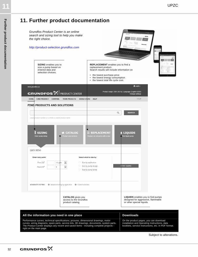
11. Further product documentation
Subject to alterations.
All the information you need in one place Downloads
Performance curves, technical specifications, pictures, dimensional drawings, motor curves, wiring diagrams, spare parts, service kits, 3D drawings, documents, system parts. The Product Center displays any recent and saved items - including complete projects - right on the main page.
On the product pages, you can download installation and Operating Instructions, data booklets, service instructions, etc. in PDF format.
SIZING enables you to size a pump based on entered data and selection choices.
Grundfos Product Center is an online search and sizing tool to help you make the right choice.
http://product-selection.grundfos.com
REPLACEMENT enables you to find a replacement product.Search results will include information on
• the lowest purchase price• the lowest energy consumption• the lowest total life cycle cost.
CATALOG gives you access to the Grundfos product catalog.
LIQUIDS enables you to find pumps designed for aggressive, flammable or other special liquids.

33
Th
e n
am
e G
run
dfo
s, t
he
Gru
nd
fos
log
o,
an
d b
e t
hin
k i
nn
ov
ate
are
re
gis
tere
d t
rad
em
ark
s o
wn
ed
by
Gru
nd
fos
Ho
ldin
g A
/S o
r G
run
dfo
s A
/S,
De
nm
ark
. A
ll ri
gh
ts r
ese
rve
d w
orl
dw
ide
.©
Co
pyr
igh
t G
run
dfo
s H
old
ing
A/S
99093908 0716
ECM: 1185372
Grundfos Kansas City17100 West 118th TerraceOlathe, Kansas 66061Phone: 913-227-3400Fax: 913-227-3500www.grundfos.us
Grundfos Canada2941 Brighton RoadOakville, Ontario L6H 6C9 CanadaPhone: +1-905-829-9533Fax: +1-905-829-9512www.grundfos.ca
Grundfos MéxicoBoulevard TLC No. 15Parque Industrial Stiva AeropuertoC.P. 66600 Apodaca, N.L. MexicoPhone: 011-52-81-8144 4000Fax: 011-52-81-8144 4010www.grundfos.mx


