10000 SE Pine Street
Portland, OR 97216
TEL: 800.852.1368
FAX: 503.262.3410
www.aimco-global.com
Using an AIMCO Gen 4 Controller on a
Rockwell PLC with Modbus TCP Authors: Kade Olson and Sam Stewart
Date: June 17, 2015
Introduction Many AIMCO torque controllers come standard with Modbus TCP. A common use is interfacing
them to an Allen-Bradley PLC for error proofing and data collection. This document is intended to
show the steps required to setup the PLC and AIMCO controller for Modbus TCP communication.
Equipment/Software • Modbus capable controller from AIMCO.
o Generation 4 controller (iEC4EGVP).
• 1769-L32E CompactLogix5332E Controller Rev 16.20.
• MVI69-MNET Modbus TCP/IP Master Module.
• RSLogix 5000 Rev v16.3.
• 4 - Ethernet cables
Hardware Setup • Connect an Ethernet cable from the CompactLogix L32E to an Ethernet switch.
• Connect an Ethernet cable from the PC to an Ethernet switch.
• Connect an Ethernet cable from the Modbus module to an Ethernet switch.
10000 SE Pine Street
Portland, OR 97216
TEL: 800.852.1368
FAX: 503.262.3410
www.aimco-global.com
• Connect an Ethernet cable from the AIMCO controller to an Ethernet switch.
10000 SE Pine Street
Portland, OR 97216
TEL: 800.852.1368
FAX: 503.262.3410
www.aimco-global.com
Initial Setup
Defining the CompactLogix L32E Module for the PLC
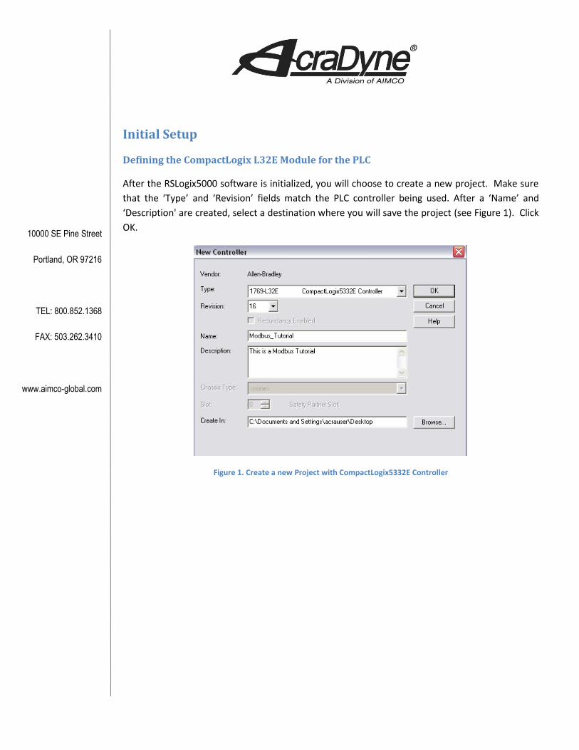
After the RSLogix5000 software is initialized, you will choose to create a new project. Make sure
that the ‘Type’ and ‘Revision’ fields match the PLC controller being used. After a ‘Name’ and
‘Description' are created, select a destination where you will save the project (see Figure 1). Click
OK.
Figure 1. Create a new Project with CompactLogix5332E Controller
10000 SE Pine Street
Portland, OR 97216
TEL: 800.852.1368
FAX: 503.262.3410
www.aimco-global.com
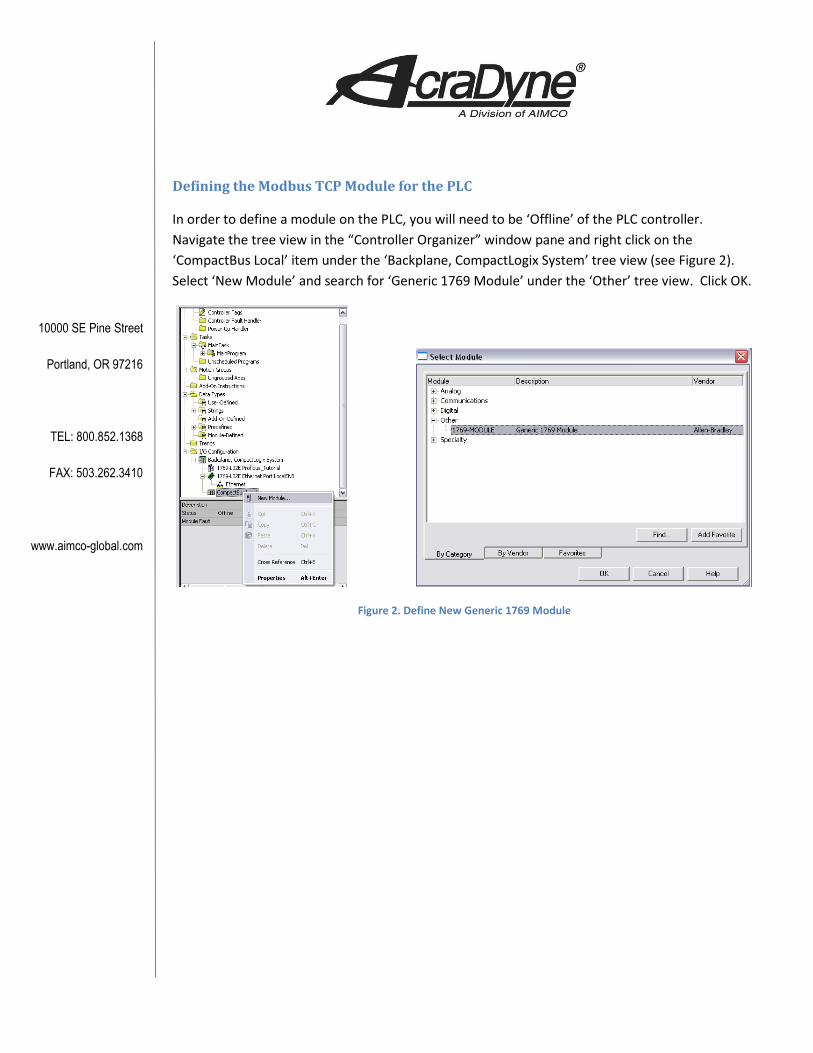
Defining the Modbus TCP Module for the PLC
In order to define a module on the PLC, you will need to be ‘Offline’ of the PLC controller.
Navigate the tree view in the “Controller Organizer” window pane and right click on the
‘CompactBus Local’ item under the ‘Backplane, CompactLogix System’ tree view (see Figure 2).
Select ‘New Module’ and search for ‘Generic 1769 Module’ under the ‘Other’ tree view. Click OK.
Figure 2. Define New Generic 1769 Module
10000 SE Pine Street
Portland, OR 97216
TEL: 800.852.1368
FAX: 503.262.3410
www.aimco-global.com
Setting up the Connection
The AIMCO controller has two connection assemblies, Input and Output. The AIMCO controller’s
produced output image (Assembly Instance 100) has a default size of 61 x (16 bit) INTS. The
AIMCO controller’s consumed input image (Assembly Instance 101) with a size of 62 x (16 bit)
INTS. The size of the inputs and outputs associates with a block size of 60 (This value is needed in
ProSoft Configuration Builder).
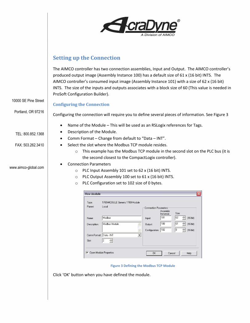
Configuring the Connection
Configuring the connection will require you to define several pieces of information. See Figure 3
• Name of the Module – This will be used as an RSLogix references for Tags.
• Description of the Module.
• Comm Format – Change from default to “Data – INT”.
• Select the slot where the Modbus TCP module resides.
o This example has the Modbus TCP module in the second slot on the PLC bus (it is
the second closest to the CompactLogix controller).
• Connection Parameters
o PLC Input Assembly 101 set to 62 x (16 bit) INTS.
o PLC Output Assembly 100 set to 61 x (16 bit) INTS.
o PLC Configuration set to 102 size of 0 bytes.
Figure 3 Defining the Modbus TCP Module
Click ‘OK’ button when you have defined the module.
10000 SE Pine Street
Portland, OR 97216
TEL: 800.852.1368
FAX: 503.262.3410
www.aimco-global.com
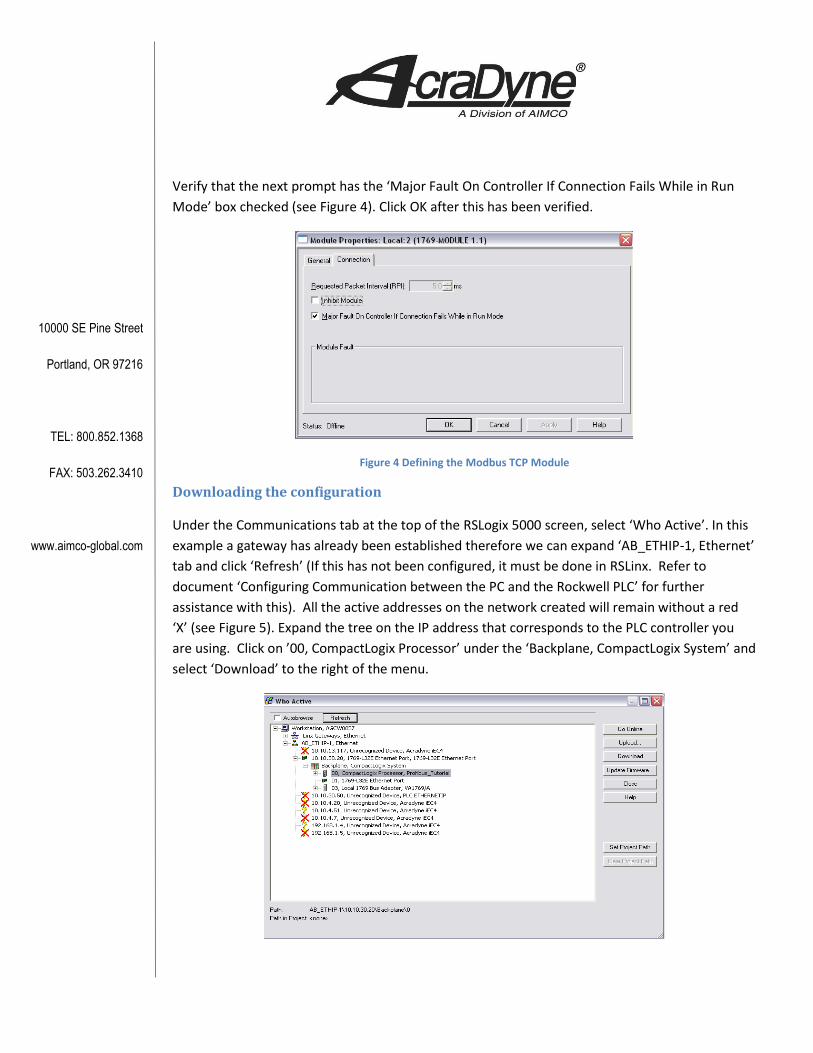
Verify that the next prompt has the ‘Major Fault On Controller If Connection Fails While in Run
Mode’ box checked (see Figure 4). Click OK after this has been verified.
Figure 4 Defining the Modbus TCP Module
Downloading the configuration
Under the Communications tab at the top of the RSLogix 5000 screen, select ‘Who Active’. In this
example a gateway has already been established therefore we can expand ‘AB_ETHIP-1, Ethernet’
tab and click ‘Refresh’ (If this has not been configured, it must be done in RSLinx. Refer to
document ‘Configuring Communication between the PC and the Rockwell PLC’ for further
assistance with this). All the active addresses on the network created will remain without a red
‘X’ (see Figure 5). Expand the tree on the IP address that corresponds to the PLC controller you
are using. Click on ’00, CompactLogix Processor’ under the ‘Backplane, CompactLogix System’ and
select ‘Download’ to the right of the menu.
10000 SE Pine Street
Portland, OR 97216
TEL: 800.852.1368
FAX: 503.262.3410
www.aimco-global.com
Figure 5 Defining the Modbus TCP Module
Follow the prompts. The program will ask if you would like to ‘Change the controller mode back
to remote run’. Click Yes.
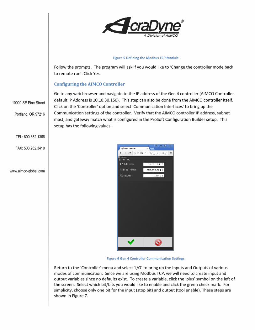
Configuring the AIMCO Controller
Go to any web browser and navigate to the IP address of the Gen 4 controller (AIMCO Controller
default IP Address is 10.10.30.150). This step can also be done from the AIMCO controller itself.
Click on the ‘Controller’ option and select ‘Communication Interfaces’ to bring up the
Communication settings of the controller. Verify that the AIMCO controller IP address, subnet
mast, and gateway match what is configured in the ProSoft Configuration Builder setup. This
setup has the following values:
Figure 6 Gen 4 Controller Communication Settings
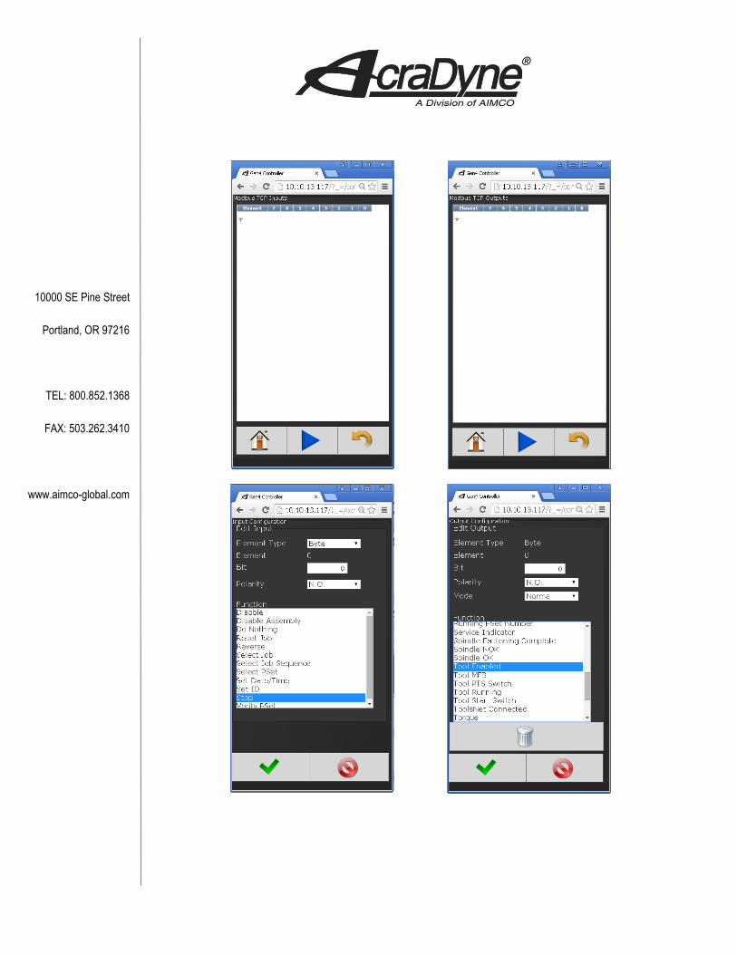
Return to the ‘Controller’ menu and select ‘I/O’ to bring up the Inputs and Outputs of various modes of communication. Since we are using Modbus TCP, we will need to create input and output variables since no defaults exist. To create a variable, click the ‘plus’ symbol on the left of the screen. Select which bit/bits you would like to enable and click the green check mark. For simplicity, choose only one bit for the input (stop bit) and output (tool enable). These steps are shown in Figure 7.
10000 SE Pine Street
Portland, OR 97216
TEL: 800.852.1368
FAX: 503.262.3410
www.aimco-global.com

10000 SE Pine Street
Portland, OR 97216
TEL: 800.852.1368
FAX: 503.262.3410
www.aimco-global.com
Figure 7 Controller Modbus TCP Settings
Pay no attention to any activated bits. These will be resolved once you import the Modbus TCP
communication ladder rung. In the meantime, check that the controller and PLC are correctly
configured by verifying that no red ‘X’ mark exists on the Modbus TCP module in the “Controller
Organizer” tree view pane in RS Logix. The status will say ‘Running’ and can also be verified by
navigating to the ‘Properties’ of the online module. If this is not the case, review the above
procedures and settings.
10000 SE Pine Street
Portland, OR 97216
TEL: 800.852.1368
FAX: 503.262.3410
www.aimco-global.com
Adding the Logic
Tags
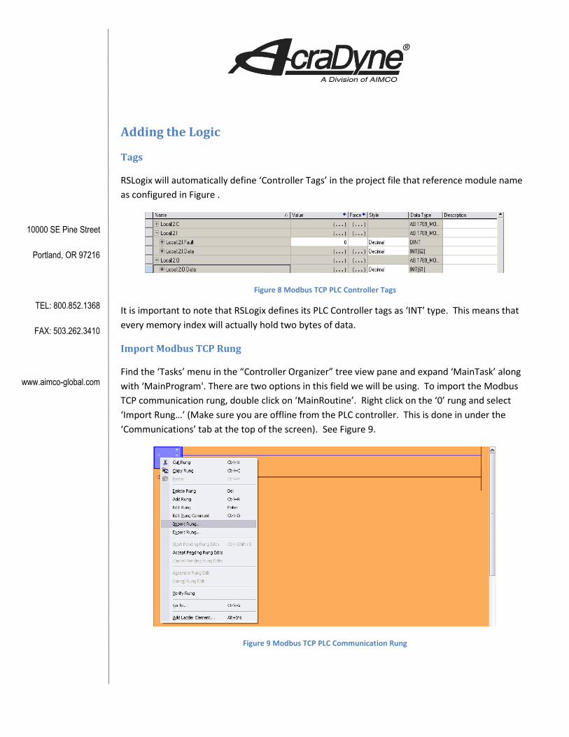
RSLogix will automatically define ‘Controller Tags’ in the project file that reference module name
as configured in Figure .
Figure 8 Modbus TCP PLC Controller Tags
It is important to note that RSLogix defines its PLC Controller tags as ‘INT’ type. This means that
every memory index will actually hold two bytes of data.
Import Modbus TCP Rung
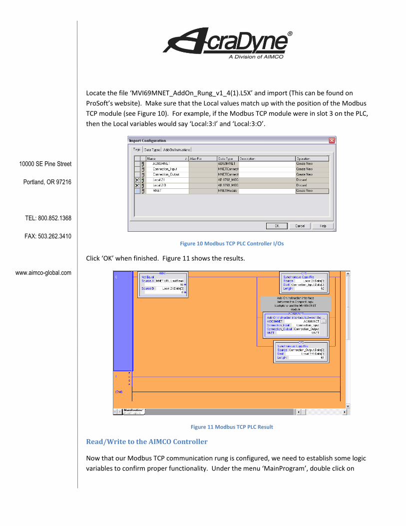
Find the ‘Tasks’ menu in the “Controller Organizer” tree view pane and expand ‘MainTask’ along
with ‘MainProgram'. There are two options in this field we will be using. To import the Modbus
TCP communication rung, double click on ‘MainRoutine’. Right click on the ‘0’ rung and select
‘Import Rung…’ (Make sure you are offline from the PLC controller. This is done in under the
‘Communications’ tab at the top of the screen). See Figure 9.
Figure 9 Modbus TCP PLC Communication Rung
10000 SE Pine Street
Portland, OR 97216
TEL: 800.852.1368
FAX: 503.262.3410
www.aimco-global.com
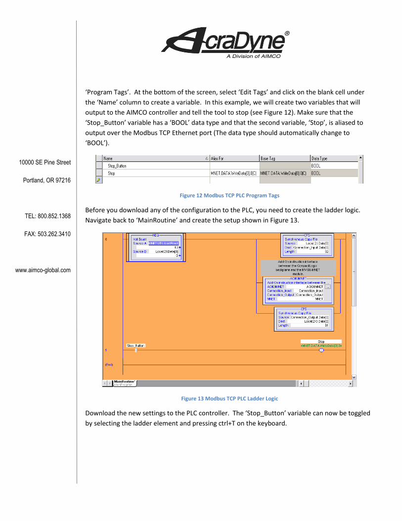
Locate the file ‘MVI69MNET_AddOn_Rung_v1_4(1).L5X’ and import (This can be found on
ProSoft’s website). Make sure that the Local values match up with the position of the Modbus
TCP module (see Figure 10). For example, if the Modbus TCP module were in slot 3 on the PLC,
then the Local variables would say ‘Local:3:I’ and ‘Local:3:O’.
Figure 10 Modbus TCP PLC Controller I/Os
Click ‘OK’ when finished. Figure 11 shows the results.
Figure 11 Modbus TCP PLC Result
Read/Write to the AIMCO Controller
Now that our Modbus TCP communication rung is configured, we need to establish some logic
variables to confirm proper functionality. Under the menu ‘MainProgram’, double click on
10000 SE Pine Street
Portland, OR 97216
TEL: 800.852.1368
FAX: 503.262.3410
www.aimco-global.com
‘Program Tags’. At the bottom of the screen, select ‘Edit Tags’ and click on the blank cell under
the ‘Name’ column to create a variable. In this example, we will create two variables that will
output to the AIMCO controller and tell the tool to stop (see Figure 12). Make sure that the
‘Stop_Button’ variable has a ‘BOOL’ data type and that the second variable, ‘Stop’, is aliased to
output over the Modbus TCP Ethernet port (The data type should automatically change to
‘BOOL’).
Figure 12 Modbus TCP PLC Program Tags
Before you download any of the configuration to the PLC, you need to create the ladder logic.
Navigate back to ‘MainRoutine’ and create the setup shown in Figure 13.
Figure 13 Modbus TCP PLC Ladder Logic
Download the new settings to the PLC controller. The ‘Stop_Button’ variable can now be toggled
by selecting the ladder element and pressing ctrl+T on the keyboard.


