
®
User instructions - MaxFlo 3 - VLENIM0052-02 02.07
�
Valtek MaxFlo 3Control Valves
Installation Operation
Maintenance
USER INSTRUCTIONS

®
User instructions - MaxFlo 3 - VLENIM0052-02 02.07
�
1 GENERAL INFORMATION1.1 Use The following instructions are designed to assist in the
unpacking, installation, and maintenance as required for Flowserve products. Product users and maintenance personnel should thoroughly review this manual prior to installing, operating, or performing any maintenance.
In most cases, Flowserve accessories, actuators and valves are designed for specific applications (e.g. with regard to medium, pressure and temperature). For this reason, they should not be used in other applications without first contacting the manufacturer.
1.2 Applicability The following instructions are applicable to the main-
tenance and installation of Flowserve MaxFlo 3 control valves. These instructions cannot claim to cover all details of all possible product variations, nor can they provide information for every possible example of in-stallation, operation or maintenance. This means that the instructions normally include only the directions to be followed by qualified personal using the product for its defined purpose. If there are any uncertainties in this respect, particularly in the event of missing product-related information, clarification must be obtained via the appropriate Flowserve sales office. Flowserve User Manuals are available at www.flowserve.com.
1.3 Terms related to safety The terms DANGER, WARNING, CAUTION, NOTE are used
in this document to highlight particular dangers and/or to provide additional information on points which may not be clearly obvious.
DANGER: Indicates that death, severe personal injury and/or substantial property damage will occur if proper precautions are not taken.
WARNING: Indicates that danger of death or severe per-sonal injury and/or property damage can occur if proper precautions are not taken.
CAUTION: Indicates that minor personal injury and/or serious damage to property can occur if the appropriate precautions are not taken.
NOTE: Indicates and provides additional technical infor-mation which may not be obvious, even to qualified per-sonnel.
Compliance with other notes, which may not be particu-larly emphasized, with regard to transport, assembly, operation and maintenance and with regard to technical documentation (e.g. in the operating instructions, prod-uct documentation, or on the product itself) is essential, in order to avoid faults, which can directly or indirectly cause severe personal injury or property damage..
1.4 Protective clothing Flowserve products are often used in problematic appli-
cations (e.g. under extremely high pressures with dan-gerous, toxic or corrosive mediums). When performng service, inspection, or repair operations, always ensure that the valve and the actuator are depressurized and that the valve has been cleaned, and that it is free of harm-ful substances. In such cases, pay particular attention to personal protection (e.g. protective clothing, gloves, glasses etc).
1.5 Qualified personnel Qualified personnel are people who on account of their
education, experience, training, and knowledge of rel-evant standards, specifications, accident prevention, and operating conditions have been authorized by those responsible for the safety of the plant to perform the necessary work, and recognize and avoid possible dan-gers.
1.6 Spare Parts Use only Flowserve original spare parts. Flowserve can-
not accept responsibility for any damages that occur from using spare parts or fastening materials from other manufacturers. If Flowserve products (especially sealing materials) have been on store for long periods of time, check them for corrosion or deterioration before putting them into use.
1.7 Service / Repair To avoid possible injury to personnel or damage to prod-
ucts, safety terms must be strictly adhered to. Modify-ing this product, substituting non-factory parts, or using maintenance procedures other than those outlined in these Installation, Operation and Maintenance Instruc-tions could drastically affect performance, be hazard-ous to personnel and equipment, and may void existing warranties. Between the actuator and the valve there are moving parts. To avoid injury, Flowserve provides pinch-point-protection in the form of cover plates, espe-cially where side-mounted positioners are fitted. If these plates are removed for inspection, service or repair special attention is required. After completing work the cover plates must be refitted. Apart from the operating instructions and the obligatory accident prevention di-rectives valid in the country of use, all recognized regu-lations for safety and good engineering practices must be followed.
STOP!
Summary
1 GENERAL INFORMATION
2 UNPACKING
3 INSTALLATION
4 QUICK-CHECK
5 PREVENTATIVE MAINTENANCE
7 VALVE DISASSEMBLY
7 BODY REASSEMBLY
8 SEAT REPLACEMENT
9 ACTUATOR REMOUNTING
10 PRINCIPLES OF SHAFT ANTI-BLOWOUT SYSTEM
11 MOUNTING ORIENTATION– AIR-TO-OPEN - diaphragm actuator
12 MOUNTING ORIENTATION – AIR-TO-CLOSE - diaphragm actuator
13 MOUNTING ORIENTATION– AIR-TO-OPEN - cylinder actuator
14 MOUNTING ORIENTATION – AIR-TO-CLOSE - cylinder actuator
15 PIPE MOUNTING ORIENTATION CODES
16 TROUBLESHOOTING

®
User instructions - MaxFlo 3 - VLENIM0052-02 02.07
3
STOP!
WARNING: Before products are returned to Flowserve for repair or service, Flowserve must be provided with a certificate that confirms that the product has been decon-taminated and is clean. Flowserve will not accept deliver-ies if a certificate has not been provided (a form can be obtained from Flowserve).
1.8 Storage In most cases, Flowserve products are manufactured
from stainless steel. Products not manufactured from stainless steel are provided with an epoxy resin coating. This means that Flowerve products are well protected from corrosion. Nevertheless, Flowserve products must be stored adequately in a clean, dry, environment. Plastic caps are fitted to protect the flange faces and prevent the ingress of foreign materials. These caps should not be removed until the valve is actually mounted into the system.
2 UNPACKING�.� While unpacking the valve, check the packing list against
the materials received. Lists describing the valve and ac-cessories are included in each shipping container.
�.� When lifting the valve from shipping container, use straps through the yoke legs. Take care to position lifting straps to avoid damage to the tubing and mounted ac-cessories.
WARNING: When lifting a valve be aware that the center of gravity may be above the lifting point. Therefore, sup-port must be given to prevent the valve from rotating. Failure to do so can cause serious injury to personnel and damage to the valve and nearby equipment.
�.3 Contact you shipper immediately if there is shipping damage.
�.4 Should any problem arise, call your Flowserve represent-ative.
DANGER: Before installation check the order number, se-rial number, and/or the tag number to ensure that the valve and actuator being installed are correct for the in-tended application.
CAUTION: Do not insulate extensions that are provided for hot or cold services.
3 INSTALLATION3.� Before installing the valve, clean the pipeline of all con-
tamination, carbon deposits, welding chips, and other foreign material. Carefully clean gasket surfaces to en-sure a tight seal. Pipelines must be correctly aligned to ensure that the valve is not fitted under tension.
3.� Fire protection must be provided by the user.
3.3 Check the direction of fluid flow to ensure that the valve is correctly installed. Flow direction is indicated by the arrow attached to the body. All installation orientations for fitting the valve into the pipeline are defined at the end of this manual.
DANGER: To avoid serious injury, keep hands, hair, cloth-ing, etc away from the plug and seat when the valve is working.
3.4 Whenever possible, the valve should be installed so that actuator is in an upright position. Vertical installation of the actuator permits easier valve maintenance.
3.5 Connect the air supply and instrument signal lines. Throt-tling control valves are equipped with a valve positioner. Connections are marked for the air supply and the in-strument signal. Check that the actuator and positioner can withstand the maximum air supply from the network. The required air supply is indicated on a sticker located on the actuator. An air regulator will be necessary in cer-tain cases in order to limit the supply pressure. A filter is recommended unless the air supplied is exceptionally clean and dry (air quality without humidity, oil, or dust as per IEC 770 and ISA-7.0.0�). All connections must be completely tight.
CAUTION: On valves equipped with air filters, the air filter must point down to perform properly.
3.6 Use the bolts indicated in table I for installing the valve in the pipeline, and then tighten alternately according to good practice. The user must in all cases confirm the capacity of the bolts to ensure a sufficiently tight gasket seal for the expected service conditions.
3.7 Be sure to provide proper overhead clearance for the actuator to allow for disassembly of the actuator from the valve body. Refer to the appropriate to the MaxFlo 3 Technical Bulletin for proper clearances. The MaxFlo 3 Technical Bulletin is available at www.flowserve.com.
STOP!
®
User instructions - MaxFlo 3 - VLENIM0052-02 02.07
4
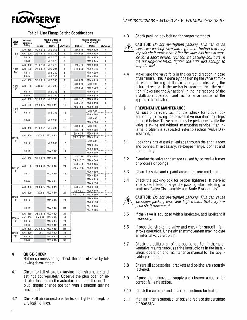
Table I: Line Flange Bolting Specifications
4 QUICK-CHECK Before commissioning, check the control valve by fol-
lowing these steps:
4.� Check for full stroke by varying the instrument signal settings appropriately. Observe the plug position in-dicator located on the actuator or the positioner. The plug should change position with a smooth turning movement.
4.� Check all air connections for leaks. Tighten or replace any leaking lines.
4.3 Check packing box bolting for proper tightness.
CAUTION: Do not overtighten packing. This can cause excessive packing wear and high stem friction that may impede shaft movement. After the valve has been in serv-ice for a short period, recheck the packing-box nuts. If the packing-box leaks, tighten the nuts just enough to stop the leak.
4.4 Make sure the valve fails in the correct direction in case of air failure. This is done by positioning the valve at mid-stroke and turning off the air supply and observing the failure direction. If the action is incorrect, see the sec-tion “Reversing the Air-action” in the instructions of the installation, operation and maintenance manual of the appropriate actuator.
5 PREVENTATIVE MAINTENANCE At least once every six months, check for proper op-
eration by following the preventative maintenance steps outlined below. These steps may be performed while the valve is in-line and without interrupting service. If an in-ternal problem is suspected, refer to section “Valve Dis-assembly”.
5.� Look for signs of gasket leakage through the end flanges and bonnet. If necessary, re-torque flange, bonnet and post bolting.
5.� Examine the valve for damage caused by corrosive fumes or process drippings.
5.3 Clean the valve and repaint areas of severe oxidation.
5.4 Check the packing-box for proper tightness. If there is a persistent leak, change the packing after referring to sections “Valve Disassembly and Body Reassembly”.
CAUTION: Do not overtighten packing. This can cause excessive packing wear and high friction that may im-pede shaft movement.
5.5 If the valve is equipped with a lubricator, add lubricant if necessary.
5.6 If possible, stroke the valve and check for smooth, full-stroke operation. Unsteady shaft movement may indicate an internal valve problem.
5.7 Check the calibration of the positioner. For further pre-ventative maintenance, see the instructions in the instal-lation, operation and maintenance manual for the appli-cable positioner.
5.8 Ensure all accessories, brackets and bolting are securely fastened.
5.9 If possible, remove air supply and observe actuator for correct fail-safe action.
5.�0 Check the actuator and all air connections for leaks.
5.�� If an air filter is supplied, check and replace the cartridge if necessary.
Valvesize
Nominal Pressure /
Rating
MaxFlo 3 flanged Size x Length
MaxFlo 3 flangeless Size x Length
Inches Metric Qty/ valve Inches Metric Qty/ valve
DN�5�"
ANSI �50 �/� X �.6� M�� X 65 8 �/� X 6.75 M�� X �70 4
ANSI 300 5/8 X 3.�� M�6 X 80 8 5/8 X 6.88 M�6 X �75 4
PN �6 M�� X 70 8 M�� X �75 4
PN 40 M�� X 70 8 M�� X �75 4
DN40�½"
ANSI �50 �/� X �.88 M�� X 70 8 �/� X 7.50 M�� X �90 4
ANSI 300 3/4 X 3.6� M�0 X 95 8 3/4 X 8.38 M�0 X ��5 4
PN �6 M�6 X 80 8 M�6 X �00 4
PN 40 M�6 X 80 8 M�6 X �00 4
DN50 �"
ANSI �50 5/8 X 3.�5 M�6 X 85 8 5/8 X 8.38 M�6 X ��5 4
ANSI 300 5/8 X 3.5 M�6 X 90 �65/8 X 3.50 M�6 X 90 4
5/8 X 8.50 M�6 X ��0 6
PN �6 M�6 X 85 8 M�6 X ��5 4
PN 40 M�6 X 85 8 M�6 X ��5 4
DN803"
ANSI �50 5/8 X 3.6� M�6 X 95 8 5/8 X �0.5 M�6 X �65 4
ANSI 300 3/4 X 4.�5 M�0 X ��0 �63/4 X 4.�5 M�0 X ��0 4
3/4 X ��.00 M�0 X �80 6
PN �6 M�6 X 85 �6 M�6 X 85 6
M�6 X �55 5
PN 40 M�6 X 95 �6 M�6 X 95 6
M�6 X �65 5
DN�004"
ANSI �50 5/8 X 3.6� M�6 X 95 �65/8 X 3.6� M�6 X 95 4
5/8 X ��.5 M�6 X �95 6
ANSI 300 3/4 X 4.5 M�0 X ��5�6 3/4 X 4.5 M�0 X ��5 4
3/4 X ��.�5 M�0 X 3�5 6
PN �6 M�6 X 85 �6 M�6 X 85 6
M�6 X �85 5
PN 40 M�0 X �00 �6 M�0 X �00 6
M�0 X 300 5
DN�506"
ANSI �50 3/4 X 3.75 M�0 X �05 �63/4 X 3.75 M�0 X �05 4
3/4 X �3.�5 M�0 X 340 6
ANSI 300 3/4 X 4.88 M�0 X ��5 �43/4 X 4.88 M�0 X ��5 8
3/4 X �4.00 M�0 X 360 8
PN �6 M�0 X �00 �6 M�0 X �00 4
M�0 X 335 6
PN 40 M�4 X ��5 �6 M�4 X ��5 4
M�4 X 350 6
DN�008"
ANSI �50 3/4 X 4.�5 M�0 X ��0 �6 3/4 X 4.�5 M�0 X 360 8
ANSI 300 7/8 X 5.5 M�� X �40 �47/8 X 5.5 M�� X �40 4
7/8 X �5.�9 M�� X 390 �0
PN �6 M�0 X �00 �4 M�0 X �00 8
M�0 X 350 8
PN 40 M�7 X �35 �4 M�7 X �35 8
M�7 X 385 8
DN�50�0"
ANSI �50 7/8 X 4.6� M�� X ��0 �4
ANSI 300 � X 6.�5 M�4 X �55 3�
PN �6 M�4 X ��0 �4
PN 40 M30 X �50 �4
DN300��"
ANSI �50 7/8 X 4.75 M�� X ��0 �4
ANSI 300 � �/8 X M�7 X �70 3�
PN �6 M�4 X ��5 �4
PN 40 M30 X �60 3�

®
User instructions - MaxFlo 3 - VLENIM0052-02 02.07
5
Item ��7 Packing box nuts
Item �09 Packing box studs
Item 80 Gland flange
Item 87 Packing follower
Item ��4 Bonnet nuts
Item �08 Bonnet studs
Item 93 Packing spacer
Item 88 Packing set
Item 99 Packing stop
Item 40 Bonnet
Item 4� Purge plug (optional)
Item 58 Bonnet gasket
Item 46 Thrust bearing
Item 5� Shaft
Item 83 Shaft bearing
Item 50 Plug
Item 84 End post bearing
Item � Body
Item �3 Shims
Item �0 SeatItem 30 Seat retainer
Item 6� End post gasket
Item ��� End post
Item ��5 End post studs
Item ��9 End post nutsFigure 1: MaxFlo 3 valve body assembly
item numbers correspond directly to the valve’s bill of material. Refer to it for specific part numbers.

®
User instructions - MaxFlo 3 - VLENIM0052-02 02.07
6
6 VALVE DISASSEMBLY
WARNING: To carry out this operation, it is essential to disconnect the valve from the pipework. Depressurize line to atmospheric pressure and drain all fluids before working on the valve. Failure to do so can cause serious injury. Remove the valve from the pipeline.
Refer to figure � to find parts according to the item num-bers.
6.� Remove the actuator from the body by separating the ac-tuator at the yoke. Refer to the installation, operation and maintenance manual for the corresponding actuator.
6.� Remove the four bonnet nuts (item ��4).
6.3 Remove the packing nuts and gland flange (item 80).
6.4 Carefully pull the shaft (item 5�) out of the body. The bonnet, thrust bearing, packing stop and packing will all slide out of the body bore as an assembly.
NOTE: At this point in the disassembly operation, the plug is inside the valve body and is only supported by the end post. When removing the end post, support the plug so it does not drop into the bottom of the valve body.
6.5 Remove the end post nuts (item ��9) and carefully re-move the end post (item ���) from the body.
6.6 Remove the plug from the body. See figure �a.
6.7 Loosen the packing-box nuts (item ��7) and remove the shaft from the bonnet by sliding it out slowly. The thrust bearing (item 46) and the shaft stop spacer (item 47, only for sizes �0 to ��”) can now be removed from the shaft.
6.8 Remove the packing follower (item 87) as well as the pack-ing (item 88), spacers (item 93) and the packing stop (item 99).
6.9 Remove the bonnet gasket (item 58) and end post gas-ket (item 6�). Clean all bearing and seal surfaces.
6.�0 Remove the shaft bearing (item 83) from the valve body. Use a suitable dowel to push the bearing out if neces-sary. Be careful not to damage the bearing.
6.�� Unscrew the seat (item 30) using the appropriate tool (see Table IV) and remove the seat (item �0) as well as the adjustment shims (item �3).
7 BODY REASSEMBLY
NOTE: Lubricate all threads, bearings and the shaft shoulder with a boron nitride paste (Molydal NB1200) or a nickel anti-seize lubricant (Permatex 77164 or equivalent). Place the valve body in a vice and clamp securely in a vertical position.
7.� Always use new packing and gaskets when reassem-bling a valve.
7.� Make sure that the shaft, bonnet bore and gasket sur-faces in the body have been thoroughly cleaned (these are sealing surfaces and it is imprtant to remove any contamination before reassembly).
7.3 Make sure that all bearing surfaces have been cleaned.
7.4 Install all end post (item ��5) and bonnet (item �08) studs.
7.5 Insert the plug in the body as shown in figure �b.
NOTE: The end post bearing (item 84) is pressed into the plug.
7.6 Place the end post gasket (item 6�) on the end post (item ���). Insert the end post into the small flanged port in the end of the body. As the end post is inserted, locate the plug (item 50) so the end post will insert into the end post bearing located in the plug.
NOTE: For valves 3’’ and larger, insert the end post with the milled faces parallel to the flanges of the valve body.
7.7 Tighten the end post nuts to finger tight.
7.8 Insert the shaft bearing (item 83) into the body until the shoulder on the bearing contacts the step in the valve body. The bearing will protrude slightly into the body gal-lery area.
7.9 Place the thrust bearing onto the shaft. Slide it up to the thrust runner. The shaft thrust bearing will surround the thrust runner.
NOTE: for sizes 10” and 12”, an end spacer (item 47) is placed above the thrust bearing.
Figure 2a: Plug Removal Figure 2b: Plug Installation
Table II: Nut tightening torques for bonnet and post
Stud Size A193-B7 A193-B8 cl2 A453-Gr660 (Nace)
M8 �� ft-lb / �6 Nm 7.5 ft-lb /�0 Nm �0.5 ft-lb /�4 Nm
M�� 43.5 ft-lb / 59 Nm �7.5 ft-lb /37 Nm 30.5 ft-lb /4� Nm
M�6 6�.5 ft-lb / 85 Nm 39 ft-lb /53 Nm 43.5 ft-lb /59 Nm
STOP!

®
User instructions - MaxFlo 3 - VLENIM0052-02 02.07
7
7.�0 Place the bonnet gasket (item 58) on the gasket step in-side the body. Gently push the bonnet into the bonnet bore.
NOTE: When installing the bonnet, orient the milled faces on the bonnet perpendicular to the flanges of the valve body.
7.�� Place the packing stop (item 99) into the bonnet, then in-stall the packing spacer (item 93) and packing as shown in figure 3.
7.�� Install bonnet nuts and tighten to finger tight.
7.�3 Install the packing follower (item 87) and gland flange (item 80), then tighten the packing nuts to finger tight.
7.�4 Tighten the bonnet and end post nuts evenly. Torque nuts to the values listed in table II.
7.�5 Install the shims (item �3) and seat ring (item �0) as described in the Seat Replacement section.
7.�6 Install the actuator and yoke as described in the installa-tion manual for the corresponding actuator.
7.�7 Install the valve into the process line as described in the installation section.
Figure 3: Packing Configurations
Standard V-ring Twin V-ring Twin V-ring Vacuum Seal Standard graphite Twin graphite
“Live Loading” system:- optional for SureGuard / XT- standard for SafeGuard
“Live Loading” system:- optional for SureGuard / XT- standard for SafeGuard
Standard SureGuardStandard SureGuard XT
Twin SureGuardTwin SureGuard XT
Standard SureGuard FiresafeStandard SureGuard XT Firesafe
Twin SureGuard FiresafeTwin SureGuard XT Firesafe
®
User instructions - MaxFlo 3 - VLENIM0052-02 02.07
8
8 SEAT REPLACEMENT
WARNING: The actuator must be removed from the valve body prior to replacing the seat ring.
8.� To replace the seat, see figures 4 and 5, and proceed as follows:
8.� Loosen the packing box nuts.
8.3 Using the appropriate retainer tool (see Table III), re-move the seat retainer. (Retainer tools are available from the factory).
8.4 Remove the seat and any shims that may be installed under the seat.
8.5 Check both seat and plug surfaces for wear and galling. Replace these parts if necessary.
8.6 Clean seat ring, seat retainer and body threads of old sealant residue. Clean parts thoroughly.
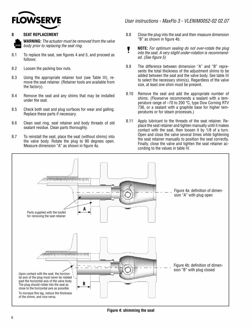
8.7 To reinstall the seat, place the seat (without shims) into the valve body. Rotate the plug to 90 degrees open. Measure dimension “A” as shown in figure 4a.
8.8 Close the plug into the seat and then measure dimension “B” as shown in figure 4b.
NOTE: For optimum sealing do not over-rotate the plug into the seat. A very slight under-rotation is recommend-ed. (See figure 5)
8.9 The difference between dimension “A” and “B” repre-sents the total thickness of the adjustment shims to be added between the seat and the valve body. See table III to select the necessary shim(s). Regardless of the valve size, at least one shim must be present.
8.�0 Remove the seat and add the appropriate number of shims. (Flowserve recommends a sealant with a tem-perature range of –70 to �00 °C, type Dow Corning RTV 736, or a sealant with a graphite base for higher tem-peratures or for steam processes.)
8.�� Apply lubricant to the threads of the seat retainer. Re-place the seat retainer and tighten manually until it makes contact with the seat, then loosen it by �/8 of a turn. Open and close the valve several times while tightening the seat retainer manually to position the seat correctly. Finally, close the valve and tighten the seat retainer ac-cording to the values in table IV.
Figure 4: shimming the seat
Upon contact with the seat, the horizon-tal axis of the plug must never be rotated past the horizontal axis of the valve body. The plug should rotate into the seat as close to the horizontal axis as possible.To increase this lag, reduce the thickness of the shims, and vice-versa.
A
B
Parts supplied with the toolkit for removing the seat retainer
Figure 4a: definition of dimen-sion “A” with plug open
Figure 4b: definition of dimen-sion “B” with plug closed
STOP!

®
User instructions - MaxFlo 3 - VLENIM0052-02 02.07
9
Figure 5: positioning of plug
Recommended plug rotation. Plug slightly under-rotated.
Table III: Shim Selection
Table IV: Seat Retainer Removal Tools and Required Torque Values
Thickness of shims available
Valve Size Rounding rule Example Chosen thickness 0.1 mm 0.15 mm 0.2 mm 0.3 mm 0.5 mm
1"DN25 to 0.05 mm
A – B = 0.�7 mmrounded to 0.�5 mm
0.1 mm0.15 mm
X X X X
1.5" to 8"DN40 à DN200
to 0.� mm A – B = 0.�7 mmrounded to 0.� mm 0.2 mm X X X X
10" – 12"DN250 – DN300
A - B - 0.3 rounded to 0.5mm
A – B = 0.9 mmA – B – 0.3 mm = 0.6 mm 0.5 mm X X X
Valve size
Face-to-FaceANSI/ISA-75.08.02, EN 558.1/2 series 36,
IEC 60534-3-2, DIN 3202 F1,EN 558-1/2 series 1
ANSI/ISA-75.08.0,EN 558-1/2 series 37-38,
IEC 60534-3-11"
DN 25Part number: �83��4.999.000
Torque: 4� ft-lbs / 55 Nm1.5"
DN 40 Part number: �83��5.999.000
Torque: �03 ft-lbs / �40 Nm2"
DN 50 Part number: �83��6.999.000
Torque: �55 ft-lbs / ��0 Nm3"
DN 80Part number: �83��7.999.000Torque: 406 ft-lbs / 550 Nm
4"DN 100
Part number: �83��8.999.000Torque: 4�8 ft-lbs / 580 Nm
6"DN 150
Part number: �83��9.999.000Torque: 959 ft-lbs / �300 Nm
8"DN 200
Part number: �83�30.999.000Torque: 70� ft-lbs / 950 Nm
Part number: �83��9.999.000Torque: 959 ft-lbs / �300 Nm
10"DN 250
Part number: �83�3�.999.000Torque: 553 ft-lbs / 750 Nm
Part number: �83�30.999.000Torque: 70� ft-lbs / 950 Nm
12"DN 300
Part number: �83�3�.999.000Torque: 75� ft-lbs / �0�0 Nm
Part number: �83�3�.999.000Torque: 553 ft-lbs / 750 Nm
Maximum limit for plug rotation. The plug should not be rotated further.
Recommended plug rotation exceeded. Setting should be
avoided.

®
User instructions - MaxFlo 3 - VLENIM0052-02 02.07
�0
9 ACTUATOR REMOUNTING
NOTE: The MaxFlo 3 valve opens in a clockwise direc-tion when looking down the valve shaft.
9.� When remounting the actuator to the valve, refer to the appropriate actuator manual.
NOTE: The actuator stroke stops must be adjusted cor-rectly to avoid any over-rotation of the plug stroke. Poor adjustment can cause damage to the valve. Pay special attention to the adjustment of the closing stop when the valve has a soft seat.
9.� Install the valve in the pipeline as indicated in the “Instal-lation” section according to the orientation recommen-dations given at the end of the manual.
Figure 6a: old design
It is possible to upgrade from the old design (prior to mid-2006) by changing the bonnet (40) and the pack-ing stop (99).
Toorderthecorrectreplacementparts,contactyourFlowserverepresentativewiththeserialnumbersofthevalvesrequiringtheupgrade.
10. PRINCIPLES OF SHAFT ANTI-BLOWOUT SYSTEM
Figure 6b: new design
NOTE: The MaxFlo 3 valve has been significantly im-proved, with even greater safety for the anti-blowout system.
The diameter of the shaft shoulder exceeds the diam-eter of the bonnet bore. Even if the thrust bearing (item 46) is not installed during reassembly, the shaft can-not pass through the bonnet.
®
User instructions - MaxFlo 3 - VLENIM0052-02 02.07
��
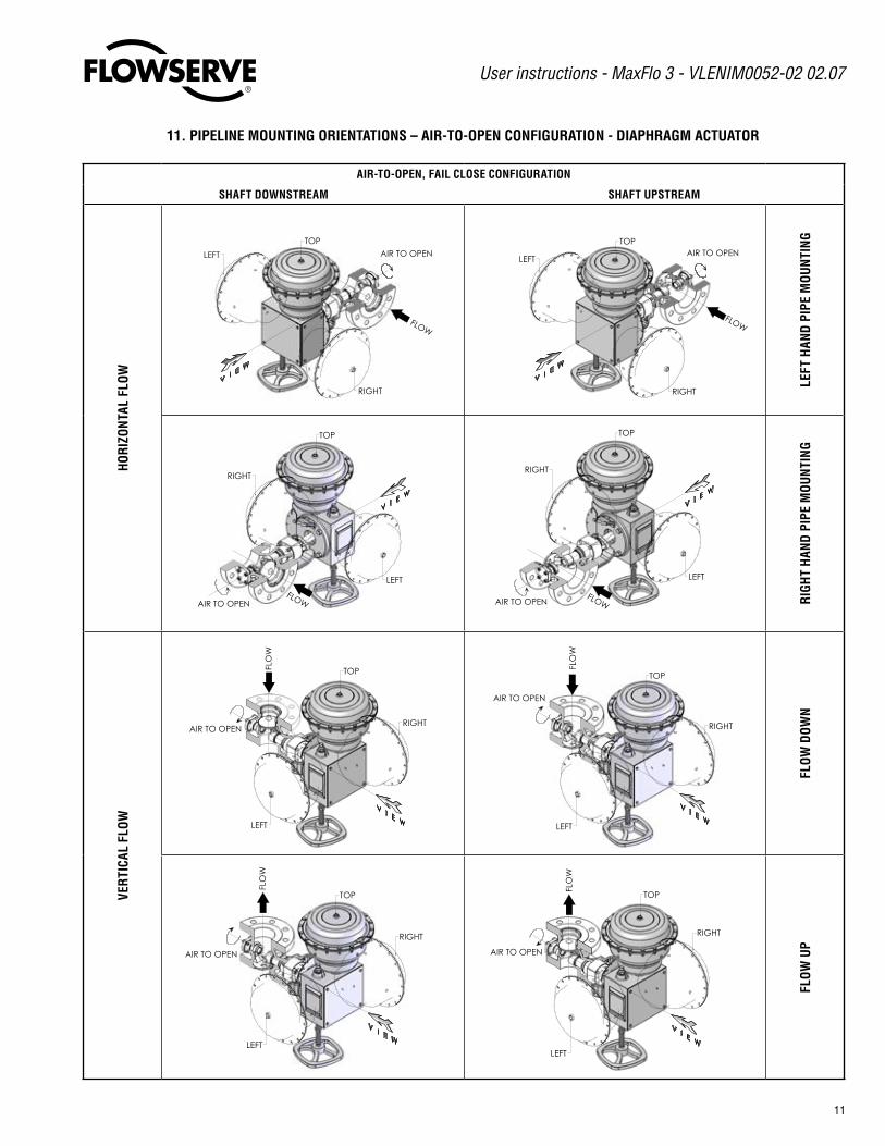
11. PIPELINE MOUNTING ORIENTATIONS – AIR-TO-OPEN CONFIGURATION - DIAPHRAGM ACTUATOR
AIR-TO-OPEN, FAIL CLOSE CONFIGURATION
SHAFT DOWNSTREAM SHAFT UPSTREAM
HO
RIZ
ON
TAL
FLO
W
LEFT
RIGHT
FLOW
AIR TO OPEN
TOP
LEFT
RIGHT
TOPAIR TO OPEN
FLOW
LEFT
HAN
D P
IPE
MO
UN
TIN
G
RIGHT
LEFT
AIR TO OPEN
TOP
FLOW
LEFT
RIGHT
AIR TO OPEN
TOP
FLOW RIG
HT
HAN
D P
IPE
MO
UN
TIN
G
VER
TICA
L FL
OW
LEFT
RIGHTAIR TO OPEN
TOPFLO
W
LEFT
RIGHT
AIR TO OPEN
TOP
FLO
W
FLO
W D
OW
N
LEFT
RIGHT
AIR TO OPEN
TOP
FLO
W
LEFT
RIGHT
AIR TO OPEN
TOP
FLO
W
FLO
W U
P

®
User instructions - MaxFlo 3 - VLENIM0052-02 02.07
��
12. PIPELINE MOUNTING ORIENTATIONS – AIR-TO-CLOSE CONFIGURATION - DIAPHRAGM ACTUATOR
AIR-TO-CLOSE, FAIL OPEN CONFIGURATION
SHAFT DOWNSTREAM SHAFT UPSTREAM
HO
RIZ
ON
TAL
FLO
W
LEFT
RIGHT
FLOW
AIR TO CLOSE
TOP
RIGHT
LEFT
AIR TO CLOSE
TOP
FLOW
LEFT
HAN
D P
IPE
MO
UN
TIN
G
LEFT
RIGHT
FLOWAIR TO CLOSE
TOP
LEFT
RIGHT
FLOWAIR TO CLOSE
TOP
RIG
HT
HAN
D P
IPE
MO
UN
TIN
G
VER
TICA
L FL
OW
LEFT
RIGHT
FLO
W
AIR TO CLOSE
TOP
LEFT
RIGHT
FLO
W
TOP
AIR TO CLOSE
FLO
W D
OW
N
LEFT
RIGHT
TOP
AIR TO CLOSE
FLO
W
LEFT
RIGHTAIR TO CLOSE
TOP
FLO
W
FLO
W U
P
®
User instructions - MaxFlo 3 - VLENIM0052-02 02.07
�3
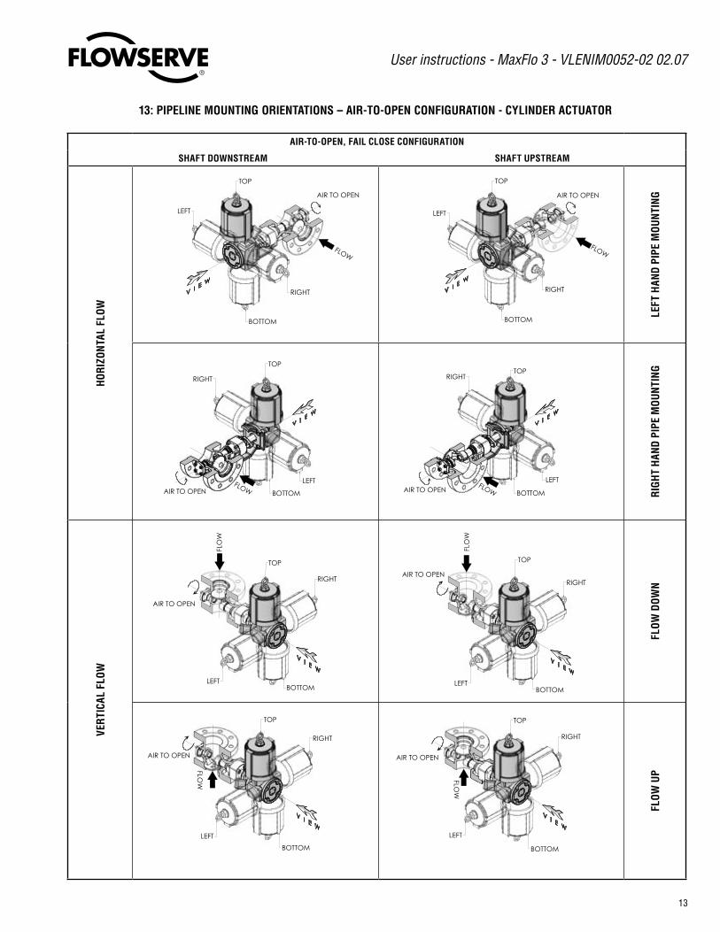
13: PIPELINE MOUNTING ORIENTATIONS – AIR-TO-OPEN CONFIGURATION - CYLINDER ACTUATOR
AIR-TO-OPEN, FAIL CLOSE CONFIGURATION
SHAFT DOWNSTREAM SHAFT UPSTREAM
HO
RIZ
ON
TAL
FLO
W
BOTTOM
LEFT
RIGHT
FLOW
AIR TO OPEN
TOP
LEFT
RIGHT
BOTTOM
TOP
AIR TO OPEN
FLOW
LEFT
HAN
D P
IPE
MO
UN
TIN
G
RIGHT
BOTTOM
LEFT
AIR TO OPEN
TOP
FLOW
RIGHT
BOTTOM
LEFTAIR TO OPEN
TOP
FLOW RIG
HT
HAN
D P
IPE
MO
UN
TIN
G
VER
TICA
L FL
OW
BOTTOMLEFT
RIGHT
AIR TO OPEN
TOP
FLO
W
BOTTOMLEFT
RIGHTAIR TO OPEN
TOP
FLO
W
FLO
W D
OW
N
RIGHT
LEFT
BOTTOM
AIR TO OPEN
TOP
FLOW
FLOW
BOTTOM
LEFT
RIGHT
AIR TO OPEN
TOP
FLOW
FLO
W U
P

®
User instructions - MaxFlo 3 - VLENIM0052-02 02.07
�4
14: PIPELINE MOUNTING ORIENTATIONS – AIR-TO-CLOSE CONFIGURATION - CYLINDER ACTUATOR
AIR-TO-CLOSE, FAIL OPEN CONFIGURATION
SHAFT DOWNSTREAM SHAFT UPSTREAM
HO
RIZ
ON
TAL
FLO
W
RIGHT
LEFT
BOTTOM
FLOW
AIR TO CLOSETOP
RIGHT
LEFT
BOTTOM
AIR TO CLOSE
FLOW
TOP
LEFT
HAN
D P
IPE
MO
UN
TIN
G
LEFT
RIGHT
BOTTOM
FLOWAIR TO CLOSE
TOP
LEFT
RIGHT
BOTTOMFLOWAIR TO CLOSE
TOP
RIG
HT
HAN
D P
IPE
MO
UN
TIN
G
VER
TICA
L FL
OW
RIGHT
LEFT
BOTTOM
FLO
W
AIR TO CLOSE
TOP
BOTTOM
LEFT
RIGHT
FLO
W
TOP
AIR TO CLOSE
FLO
W D
OW
N
BOTTOM
LEFT
RIGHT
TOPAIR TO CLOSE
FLOW
BOTTOM
LEFT
RIGHT
AIR TO CLOSE
TOP
FLOW
FLO
W U
P

®
User instructions - MaxFlo 3 - VLENIM0052-02 02.07
�5
16. TROUBLESHOOTING
Failure Probable Cause Corrective ActionValve moves to failure position, exces-sive air bleeding from transfer case
�. Failure of cylinder actuator O-ring �. Replace actuator O-ring�. Failure of sliding seal assembly in cyl-
inder actuator�. Repair or replace sliding seal assembly
Jerky shaft rotation �. Overtightened packing �. Retighten packing box nuts to slightly over finger-tight for V-ring packing, �4 ft-lbs/�9 Nm for braided packing.
�. Improper adjustment of lever arm on shaft causing arm to contact transfer case
�. Redjust lever arm (see step � in Actuator Remounting)
3. Cylinder wall of actuator not lubri-cated
3. Lubricate cylinder wall with silicone lubricant
4. Worn piston O-ring allowing piston to gall on cylinder wall
4. Replace O-ring; if galling has occurred replace all damaged parts
5. Worn actuator stem O-ring causing actuator stem to gall on stem collar
5. Replace O-ring; if actuator stem is galled replace it
6. Worn (or damaged) thrust bearings, shaft bearing or packing followers
6. Disassemble and inspect parts; replace any worn or dam-aged parts
Excessive leakage �. Improper adjustment of external stroke stops
�. See Actuator Remounting
�. Improper seat adjustment �. See Seat Replacement3. Worn or damaged seat 3. Replace seat4. Damaged plug seating surface 4. Replace plug5. Improper handwheel adjustment act-
ing as limit stop5. Adjust handwheel until plug seats properly
Leakage through line flanges �. Dirty line gasket surfaces �. Clean gasket surfaces and reinstall valve�. Improper sealing of line flanges �. Tighten line flanges evenly and completely (see Table � for
proper torque)3. Flange or pipe misalignment 3. Reinstall valve in line; check piping system
Leakage through packing box �. Loose packing box nuts �. Tighten packing box nuts to slightly over finger-tight for V-ring packing, �4 ft-lbs/�9 Nm for braided packing.
�. Worn or damaged packing �. Replace packing3. Dirty or corroded packing 3. Clean body bore and stem, replace packing
Valve slams, wont open, or causes se-vere water hammer
�. Improper valve installation �. See step � in Installation and correct flow direction
Shaft rotates, plug remains open or closed
�. Broken shaft �. Replace shaft, make sure plug does not overstroke and contact plug stop
Actuator operates, shaft does not rotate �. Broken internal actuator parts �. Refer to appropriate actuator maintenance instructionsLeakage through bonnet joint; leakage from end post
�. Loose bolting or damaged gasket �. Tighten bolting as recommended in Table II�. Dirty gasket surfaces �. Clean gasket surfaces, replace gaskets and retighten bolt-
ing per Table II
3 - Air Action 4 - Pipe Configuration 5 - Actuator Orientation 6 - Shaft Direction
O Air-to-open - ATO L Left Hand Mounting L Left U Shaft Upstream
C Air-to-close - ATC R Right Hand Mounting R Right D Shaft Downstream
D Flow Down T Top (Default)
U Flow Up B Bottom*
AT3 4 5 6
* Not available on diaphragm actuators
15 PIPE MOUNTING ORIENTATION CODES
®
User instructions - MaxFlo 3 - VLENIM0052-02 02.07
�6
Flowserve CorporationFlow Control�350 N. Mt. Springs ParkwaySpringville, UT 84663USAPhone: 80� 489 86��Fax: 80� 489 37�9
Flowserve S.A.S.��, avenue du QuebecB.P. 6459�965 Courtaboeuf CedexFrancePhone: 33 (0) � 60 9� 3� 5�Fax: 33 (0) � 60 9� 3� 99
Flowserve Pte Ltd.�� Tuas Avenue �0Singapore 6388�4SingaporePhone: 65 6868 4600Fax: 65 686� 4940
Flowserve Australia Pty Ltd.�4 Dalmore DriveScoresby, Victoria 3�79AustraliaPhone: 6� 7 3�686866Fax: 6� 7 3�685466
Flowserve Ltda.Rua Tocantins, ��8São Caetano do Sul, SP 09580-�30BrazilPhone: 55 �� ��69 6300Fax: 55 �� ��69 63�3
FCD VLAIM0052-01 – 02/07 (Replaces VLAIM052-00)
Flowserve Corporation has established industry leadership in the design and manufacture of its products. When properly selected, this Flowserve product is designed to perform its intended function safely during its useful life. However, the purchaser or user of Flowserve products should be aware that Flowserve products might be used in numerous applications under a wide variety of industrial service conditions. Although Flowserve can (and often does) provide general guidelines, it cannot provide specific data and warnings for all possible applications. The purchaser/user must therefore assume the ultimate responsibility for the proper sizing and selection, installation, operation, and maintenance of Flowserve products. The purchaser/user should read and understand the Installation Operation Maintenance (IOM) instructions included with the product, and train its employees and contractors in the safe use of Flowserve products in connection with the specific application.
While the information and specifications contained in this literature are believed to be accurate, they are supplied for informative purposes only and should not be considered certified or as a guarantee of satisfactory results by reliance thereon. Nothing contained herein is to be construed as a warranty or guarantee, express or implied, regarding any matter with respect to this product. Because Flowserve is continually improving and upgrading its product design, the specifications, dimensions and information contained herein are subject to change without notice. Should any question arise concerning these provisions, the purchaser/user should contact Flowserve Corporation at any one of its worldwide operations or offices.
© �006 Flowserve Corporation, Irving, Texas, USA. Flowserve is a registered trademark of Flowserve Corporation.
To find your local Flowserve representative please use the Sales Support Locator System found at:
www.flowserve.com/contact.htm
or call USA 80� 489-86��


