
07A1-W-0028a
VC-V20A(VCB)
Medium Voltage Switchgear/Controlgear
VC-V20A(VCBComply with IEC62271-200
24kV金属閉鎖形スイッチギヤ/コントロールギヤ
Internet address : http://www.fujielectric.co.jp
Information in this catalog is subject to change without notice.2017-08(2017H/2016G)ODP1.5FOLS Printed in Japan本資料の内容は製品改良などのために変更することがありますのでご了承ください。
安全に関するご注意*ご使用の前に,「取扱説明書」や「仕様書」などをよくお読みいただくか,当社またはお買上の販売店にご相談のうえ,正しくご使用ください。*取扱いは当該分野の専門の技術を有する人が行ってください。
Gate City Ohsaki, East Tower, 11-2, Osaki 1-chome, Shinagawa-ku, Tokyo 141-0032, JapanPhone : (03)5435-7111
(03)5435ー7111〒141ー0032 東京都品川区大崎1ー11ー2 (ゲートシティ大崎イーストタワー)

優れた適用性
コンパクトなデザイン
高い安全性
Excellent applicability
Compact design
High level of safety
富士VC-V20Aシリーズは,過去35年におよぶ海外向けSWGRを生産してきた豊富な実績をもとに開発・製品化されました。真空遮断器︵VCB︶を使用した金属閉鎖形スイッチギヤで,定格電圧24kVの一般的な電力配電システムに使用するよう設計された製品です。また、第三者認証機関︵STLメンバー)にてIEC規格︵IEC62271-200 ed2.0︶の認証を取得しています。
VC-V20Aは色々な産業設備や電力プラントで幅広い定格(24 kV, 1250A, 25kAまで)に適用できるスイッチギヤです。盤幅を選択することで適切なシステムを計画できます。
最新の絶縁技術を有効活用し、パネルフレームを非常にコンパクトに設計しています。VC-V20Aは設置スペースを満足するだけでなくコンパクトで軽量になります。
VC-V20Aは,金属閉鎖形で,完璧なインターロックを有する安全設計です。引出形機器である遮断器は,完全な機械的インターロックを有し,誤操作を防止します。さらに,誤操作を避けるため南京錠を取り付けられます。
安定した遮断性能 Stable circuit breaking performance
優れた絶縁回復特性により,小電流から短絡電流まであらゆる電流を短いアーク時間で遮断するとともに,遮断器にとって過酷な異相地絡遮断・脱落遮断においても安定した遮断性能を発揮します。
The excellent insulation recovery characteristics of the vacuum interrupter allow it to react quickly from small current to short-circuit currents, and also to exhibit a stable interrupting perfomance in double earth fault and out-of-phase currents.
The VC-V20A series switchgear can be applied to systems in a wide rating range (up to 24 kV, 1250 A, 25 kA) for use in a variety of industrial facilities and power plants.The panel width can be selected enabling the planning of a suitable system confi guration.
We have designed the panel frame to be very compact by effectively utilizing the latest insulation technology.The compact design of the VC-V20A series not only satisfi es installation space requirements but also makes it lightweight.
With its metal enclosure and perfect interlock, the VC-V20A series is designed for safety.The withdrawable vacuum circuit breaker has a complete mechanical interlock to prevent operating errors.In addition, it can be padlocked to prevent operating errors.
保守点検 Maintenance and inspections
VCBは,長い機械的,電気的寿命を実現しています。また、引出形のため、保守点検が容易です。
Vacuum circuit breakers have a long mechanical and electrical service life.Moreover, maintenance and inspection are easy because the vacuum circuit breaker is withdrawable.
The Fuji Electric VC-V20A series was developed and commercialized based on our extensive track record of manufacturing switchgears for overseas installations over the past 35 years. Equipped with a vacuum circuit breaker (VCB) and housed in a metal enclosure, this series is designed for use in general power distribution systems with a rated voltage of 24 kV.In addition, we have obtained IEC standard (IEC 62271-200 ed 2.0) certifi cate by a third party certifi cation body (a Short-Circuit Testing Liaison (STL) member).
特 長 FEATURES1.
制御室Control compartment
引出形真空遮断器Withdrawable vacuum circuit breaker
PF付変圧器Fused Voltage Transeformer
自然換気式水平母線Self-cooled horizontal busbars
遮断器室Circuit breaker compartment
強化ガラス監視窓Reinforced Inspection windows
保護リレーMultiple protection relay
図1-1�外観図Fig. 1-1 External appearance
1
Medium Voltage Switchgear24kV 金属閉鎖形スイッチギヤおよびコントロールギヤ
※1 高電圧スイッチギヤ PART200。定格交流電圧1kV超過52kV以下の金属閉鎖形スイッチギヤ及びコントロールギヤ
※2 オプション
*1. AC metal-enclosed switchgear and controlgear for rated voltages above 1 kV and up to and including 52 kV.
*2. Optional.
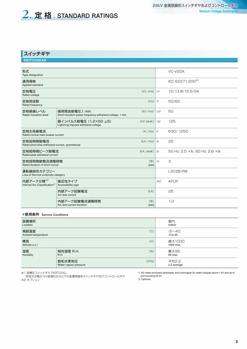
形式Type designation
VC-V20A
適用規格Applied standard
IEC 62271-200※1
定格電圧 〔kV, rms〕Rated voltage
Ur 12/13.8/15.5/24
定格周波数 〔Hz〕Rated frequency
fr 50/60
定格絶縁レベルRated insulation level
商用周波耐電圧,1�min. 〔kV, rms〕Short-duration power frequency withstand voltage, 1 min.
Ud 50
雷インパルス耐電圧�(1.2×50�μS) 〔kV, peak〕Lightning impulse withstand voltage
Up 125
定格主母線電流 〔A, rms〕Rated normal main busbar current
lr 630/ 1250
定格短時間耐電流 〔kA, rms〕Rated short-time withstand current, symmetrical
lk 25
定格短時間ピーク耐電流 〔kA, peak〕Rated peak withstand current
lp 50 Hz: 2.5 ×lk, 60 Hz: 2.6 ×lk
定格短時間耐電流通電時間 〔秒〕Rated duration of short-circuit [sec]
tk 3
運転継続性カテゴリーLoss of Service continuity category
LSC2B-PM
内部アーク分類※2
Internal Arc Classifi cation*2接近性タイプAccessibility type
IAC AFLR
内部アーク試験電流 〔kA〕Arc test current
25
内部アーク試験電流通電時間 〔秒〕Arc test current duration [sec]
1.0
●使用条件 Service Conditions
設置場所Location
屋内 Indoor
周囲温度 〔℃〕Ambient temperature
-5~40 -5 to 40
標高 〔m〕Altitude a.s.l.
最大1000 1000 max.
湿度Humidity
相対湿度�R.H. 〔%〕R.H.
最大95 95 max.
飽和水蒸気圧 〔kPa〕Water vapour pressure
平均2.2 2.2 average
定 格 STANDARD RATINGS2.
スイッチギヤSWITCHGEAR
2

形式Type designation
HS2520F-□Mf-A *1
適用規格Applied standard
IEC 62271-100 (2012)
定格電圧 〔kV, rms〕Rated voltage
Ur 24
定格周波数 〔Hz〕Rated frequency
fr 50/60
定格電流︵自然冷却︶ 〔A〕Rated normal current (self-cooling)
lr 630/1250
定格絶縁レベルRated insulation level
商用周波耐電圧,1�min. 〔kV, rms〕Short-duration power frequency withstand voltage, 1 min.
Ud 50
定格インパルス耐電圧 〔kV, peak〕Lightning impulse withstand voltage
Up 125
定格短時間耐電流 〔kA, rms〕Rated short-time withstand current
lk 25
定格短時間ピーク耐電流 〔kA, rms〕Rated peak withstand current
lp 50 Hz: 2.5 ×lk, 60 Hz: 2.6 ×lk
定格短時間耐電流通電時間 〔sec〕Rated duration of short-circuit
tk 3
定格短絡遮断電流 〔kA, rms〕Rated short-circuit breaking current
lsc 25
定格短絡投入電流 〔kA, peak〕Rated short-circuit making current
lp 50 Hz: 2.5 ×lk, 60 Hz: 2.6 ×lk
定格制御電圧 〔V DC〕Rated control voltage
Ua 100, 110, 200, 220
定格動作責務Rated operating sequence
O-3 min.-CO-3 min.-CO O-0.3 sec.-CO-3 min.-CO
閉路操作Closing operation
モーター電流︵DC�110V︶ 〔A〕Motor current (at 110 V DC)
2
スプリングチャージ時間 〔sec〕Spring charging time
4
閉路制御電流(DC�110V) 〔A〕Closing control current (at 110V DC)
4
開路制御電流︵DC�110V︶ 〔A〕Tripping control current (at 110V DC)
4
補助開閉器︵接点︶Auxiliary switch (contacts)
6a6b
質量 〔kg〕Weight
M 170
*1: □には数字が入ります。 □ is fi lled with numeric character. 1250A: 12 630A: 06
図2-1�引出し形真空遮断器Fig. 2-1 Withdrawable vacuum circuit breaker
真空遮断器VACUUM CIRCUIT BREAKER
図2-1�引出し形真空遮断器Fig. 2-1 Withdrawable vacuum circuit breaker
3

Medium Voltage Switchgear24kV 金属閉鎖形スイッチギヤおよびコントロールギヤ
● VC-V20Aは屋内に設置するよう設計され,外被は薄板構造です。図3-1に示すようにスイッチギヤは,遮断器室,母線室,ケーブル室,制御室の4区画から構成されます。
● 制御ケーブルの端子台は制御室に設けています。さらに,VC-V20Aは,仕切りを通って他のコンパートメントへホットガスの影響が最小限となるように設計されています。
● 遮断器室には充電部への接触事故を防止するため自動安全シャッターを設けています。
● With the thin plate structure of its enclosure, the VC-V20A series is designed to be installed indoors. As shown in Figure 3-1, the switchgear is confi gured with four sections: circuit breaker compartment, busbar compartment, cable compartment, and control compartment.
● The terminal block for the control cable is provided in the control compartment.In addition, the VC-V20A series is designed to minimize the effects of hot gas passing through partitions into other compartments.
● Automatic safety shutters are provided at the disconnecting switches on the busbar and the circuit sides to prevent accidental contact with the charging unit.
● An automatic safety shutter is installed in the circuit breaker compartment to prevent accidental contact with the charging unit.
● 主母線は,導電性の高い銅導体で製作しています。
● 母線は引抜き高導電率銅を使用しており、絶縁材料で被覆されています。
● The main busbar is made of copper conductor.
● The busbar is made from high conductivity copper and is covered with insulation.
① アークガス冷却装置(オプション︶ Arc gas cooling device (optional)
② 制御室Control compartment
③ 遮断器室Circuit breaker compartment
④ 母線室Busbar compartment
⑤ ケーブル室Cable compartment
⑥ 真空遮断器Vacuum circuit breaker
⑦ 接地開閉器︵オプション︶Earthing switch (optional)
⑧ 接地母線Earthing busbar
図3-2�すずメッキ主母線︵空気絶縁︶Fig. 3-2 Main busbars (air insulated) with tin
plating
図3-1�断面図Fig. 3-1 Sectional view
閉鎖箱と仕切りENCLOSURE AND PARTITIONS
母 線BUSBAR
構 造 CONSTRUCTION3.
4

● 引出形VCBはコンパートメント内で以下の3通りの状態を有しています。
(a) “運転”位置主コンタクトと補助回路が接続
(b) “試験”位置主コンタクトは断路,補助回路が接続
(c) “断路”位置主コンタクトと補助回路は断路b),c)は同じ位置で,c)は補助回路プラグが外れた状態
● The withdrawable vacuum circuit breaker has the following three states inside the compartment.
(a) "Service" positionThe main contact and the auxiliary circuit are connected.
(b) "Test" positionThe main contact is disconnected, and the auxiliary circuit is connected.
(c) "Disconnected" position The main contact and the auxiliary circuit are disconnected. While B) and C) are in the same position, C) is in a state in which the auxiliary circuit plug is disconnected.
● 安全インタロック以下の機械的インタロックを安全のために装備しています。
(1) CBが開状態の時のみ運転位置もしくは試験位置へ挿入、引出しが可能
(2) CBが運転位置、試験位置のみCBを閉可能
(3) 制御回路コネクタを接続した状態でのみCBを運転位置へ挿入が可能
(4) 扉が閉じた状態でのみ運転位置もしくは試験位置へ挿入、引出しが可能
(5) 扉はCBが試験位置の状態でのみ開閉可能
● 互換性630A,1250A共に構造が共通のため、 互換性を有しています。
● Safety interlocksThe following mechanical interlocks are provided for safety.
(1) The circuit breaker can be inserted and drawn out to the service position or test position only while it is in the open state.
(2) The circuit breaker can be closed only while it is in the service position or test position.
(3) The circuit breaker can be inserted into the service position only while the control circuit connector is connected.
(4) Only while the door is closed, the circuit breaker can be inserted and drawn out to the service position or test position.
(5) The door can be opened / closed only while the circuit breaker is in the test position.
● CompatibilityThe 630A and 1250A models both have the same structure and are compatible.
図3-3�真空遮断器詳細Fig. 3-3 Vacuum circuit breaker details
ON/OFF表示ON/OFF indicator
操作回数カウンタOperation counter
投入スプリングのマニュアルチャージハンドル挿入口
Manual spring charge handle hole
手動閉路ボタンManual close button
投入スプリングのチャージ状態表示Spring charge indicator
挿入/引出し機構Insert / Draw-out mechanism
挿入・引出し操作Insert / Draw-out operation
真空遮断器(VCB)VACUUM CIRCUIT BREAKER (VCB)
制御回路コネクタControl circuit plug-in terminal
手動開路ボタンTripping push button
5

Medium Voltage Switchgear24kV 金属閉鎖形スイッチギヤおよびコントロールギヤ
遮断器室には母線室とケーブル室の断路接続部に自動操作式安全シャッタが設置されています。このシャッタは金属製で遮断器を引き出すことで自動的に閉まります。試験や点検のため各シャッタは個別に手で動かすことができ,開位置で保持したままロックすることができます。この保持機構は,遮断器を‘運転’位置に挿入することによって自動的に解除されます。また、VCBが試験位置ではシャッタは閉状態となるように構成されています。
● 上図に示されるように,シャッタは母線側とケーブル側に設けてあり,上部シャッタおよび下部のシャッタは個々に開閉することができます。また,シャッタ閉状態で南京錠(オプション)を取付けることができます。
Automatic safety shutters are installed in the circuit breaker compartment to cover the primary junction contacts from the busbar compartment and cable compartment. The shutters are made of metal and close automatically when the circuit breaker is withdrawn. Each of the shutters can be separately moved manually for testing and inspection, and can be locked in the open position. The shutter hold-open mechanism is released automatically when the circuit breaker is set to the "service" position.Also, the shutters are confi gured to be in the closed state when the vacuum circuit breaker is in the test position.
● As shown below, the shutters operate on the busbar and cable sides. The shutters for the upper and lower primary junctions can be closed and opened individually, and canbe (optionally) padlocked in the closed position.
● シャッタは金属製で,以下の表示や色別(オプション)を指定できます。
例:母線側シャッタに「BUSBAR」:赤色︵文字色:白︶ケーブル側シャッタに「CABLE」:黄色︵文字色:白︶
● The shutters are made of metal and the following sign can be (optionally) provided.
Example:[BUSBAR] marking on shutter on the busbar side: Red (Lettering color: white)[CABLE] marking on shutter on the cable side: Yellow (Lettering color: white)
図3-6�シャッタ閉位置で南京錠をかけた状態︵オプション︶Fig. 3-6 Shutter padlocked in the closed position (Option)
図3-4�シャッタ開状態︵VCB︶Fig. 3-4 Shutters open (VCB)
図3-5�シャッタ閉状態︵VCB︶Fig. 3-5 Shutters closed (VCB)
個別駆動操作の金属シャッタMetal shutter by individual operation
南京錠Padlock (option)
安全シャッタSAFETY SHUTTERS
6

● 接地母線は銅導体を適用しています。
● メッキ無の接地母線を標準としています。要求により,すずメッキの接地母線に変更が可能です。(オプション)
● 接地母線は,全幅の長さに亘って取り付けられ,両端で接地ケーブルを接続できます。
● 接地母線は,ケーブル室の下のカバーを外すことにより,容易に接近できます。
● 接地母線は万一、短絡事故が発生しても短絡事故電流に耐える構成となっています。
● The earthing busbar is made of copper conductor.
● An unplated earthing busbar is provided as the standard specifi cation. A plated earthing busbar can be provided upon request. (Option)
● An earthing busbar is installed along the full length of the switchgear structure, with provision for earth cable connection at each end.
● The earthing busbar is easily accessible by removing the cover at the bottom of the cable compartment.
● The earthing busbar is confi gured to withstand the short circuit fault current in the event that short circuit accident occurs.
図3-9�接地母線︵パネルの後ろから見る︶Fig. 3-9 Earthing busbar (viewed from rear of panel)
● 変流器︵CT︶はケーブルコンパートメントに取り付けられます。 ● Connection is possible from the top and bottom of the current transformer (CT) compartment.
図3-7�ケーブルコンパートメントに取付けられた変流器Fig. 3-7 Current transformers are installed in the cable compartment
ケーブルコンパートメント/変流器CABLE COMPARTMENT/ CURRENT TRANSFORMER
● 補助リレー,端子台,ヒューズなど必要な制御装置は,制御室に配置します。
● ダクトとバンド固定により,制御配線を体系的に整頓しています。
● 制御回路の外線ケーブルはコンパートメントの上下から接続が可能です。
● 扉に設置された機器への配線は,扉の開閉によるダメージをビニール保護チューブによって保護されています。
● Necessary control equipment such as auxiliary relays, terminal blocks and fuses are located in the control compartment.
● Ducting and bundling ensure that control wiring is systematic and neat.
● External cable for the control circuit can be connected from the top and bottom of the compartment.
● Plastic protective tubing is provided to prevent damage to wiring connected to devices installed in the door when the door is opened and closed.
図3-8�制御室Fig. 3-8 Control compartment
配 線WIRING
接地母線EARTHING BUSBAR
7
Medium Voltage Switchgear24kV 金属閉鎖形スイッチギヤおよびコントロールギヤ
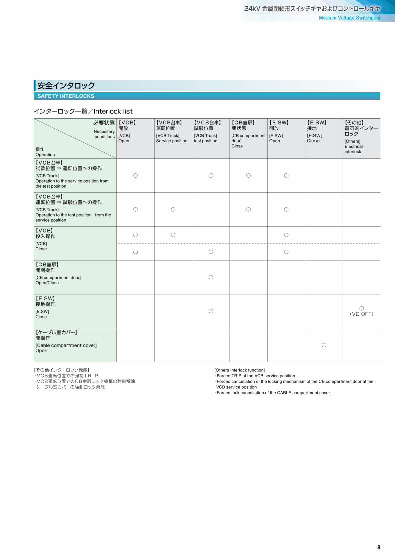
インターロック一覧/Interlock�list
必要状態Necessaryconditions
操作Operation
【VCB】開放[VCB]Open
【VCB台車】運転位置[VCB Truck]Service position
【VCB台車】試験位置[VCB Truck]test position
【CB室扉】閉状態[CB compartment door]Close
【E.SW】開放[E.SW]Open
【E.SW】接地[E.SW]Close
【その他】電気的インターロック[Others]Electrical interlock
【VCB台車】試験位置�⇒�運転位置への操作[VCB Truck]Operation to the service position from the test position
○ ○ ○ ○
【VCB台車】運転位置�⇒�試験位置への操作[VCB Truck]Operation to the test position from the service position
○ ○ ○ ○
【VCB】投入操作[VCB]Close
○ ○ ○
○ ○ ○
【CB室扉】開閉操作[CB compartment door]Open/Close
○
【E.SW】接地操作[E.SW]Close
○ ○(VD OFF)
【ケーブル室カバー】開操作[Cable�compartment�cover]Open
○
【その他インターロック機能】 ・VCB運転位置での強制TRIP ・VCB運転位置でのCB室扉ロック機構の強制解除 ・ケーブル室カバーの強制ロック解除
[Others Interlock function] ・Forced TRIP at the VCB service position ・ Forced cancellation of the locking mechanism of the CB compartment door at the
VCB service position ・Forced lock cancellation of the CABLE compartment cover
安全インタロックSAFETY INTERLOCKS
8

正面
150
165
420
255
600600
1045
1780
65
1910
3074030
主回路ケーブル引込口Power cable entrance
800 800
600
800 800 800 800
600
800 800
600 600
800 800
8000
基礎ボルト穴φ15x20Foundation bolt hole
制御ケーブル引込口Control cable entrance
65
F.L
191040
1950
CT: 計器用変流器 Current Transformer
ES: 接地開閉器 Earthing Switch
LA : 避雷器(オプション) Lightning Arrester (Option)
DS : 断路器 Disconnect switch
VCB : 真空遮断器 Vacuum Circuit Breaker
VT : 計器用変圧器 Voltage Transformer
PF: パワーヒューズ Power Fuse
2回線受電の例EXAMPLE OF TWO-LINE INCOMING POWER
SWGRの構成 SWITCHGEAR ARRANGEMENT4.
正面FRONT VIEW
単線結線図BLOCK SKELETON
基礎図BASIC VIEW
側面図SIDE VIEW
9
Medium Voltage Switchgear24kV 金属閉鎖形スイッチギヤおよびコントロールギヤ
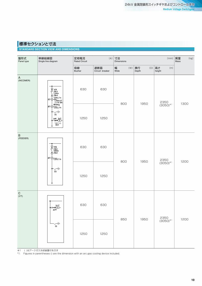
標準セクションと寸法STANDARD SECTION VIEW AND DIMENSIONS
盤形式Panel type
単線結線図Single line diagram
定格電流� 〔A〕Rated Circuit
寸法� 〔mm〕Dimensions
質量� 〔kg〕Mass
母線Bushar
遮断器Circuit breaker
幅� 〔W〕Wide
奥行� 〔D〕Depth
高さ� 〔H〕height
A(INCOMER)
630 630
800 1950 2350 (3050)※1 1300
1250 1250
B(FEEDER)
630 630
800 1950 2350 (3050)※1 1200
1250 1250
C(VT)
630 630
850 1950 2350 (3050)※1 1200
1250 1250
※1 ( )はアークガス冷却装置付を示す*1: Figures in parentheses () are the dimension with an arc gas cooling device included.
10

盤形式Panel type
単線結線図Single line diagram
定格電流� 〔A〕Rated Circuit
寸法� 〔mm〕Dimensions
質量� 〔kg〕Mass
母線Bushar
遮断器Circuit breaker
幅� 〔W〕Wide
奥行� 〔D〕Depth
高さ� 〔H〕height
D(BUS COUPLER)
630 630
800 1950 2350 (3050)※1 1200
1250 1250
E(BUS COUPLER)
630 630
800 1950 2350 (3050)※1 1200
1250 1250
※1 ( )はアークガス冷却装置付を示す*1: Figures in parentheses () are the dimension with an arc gas cooling device included.
11

Medium Voltage Switchgear24kV 金属閉鎖形スイッチギヤおよびコントロールギヤ
● 正面/背面構造
● 保護等級閉鎖箱:IP4X内部仕切り:IP2X
● Front and rear structure
● International Protection CodeEnclosure: IP4XInternal partitions : IP2X
ポジションPosition
構造Structure
蝶番位置Hinge location
把手位置Handle location
遮断器室正面Front of breaker compartment
ヒンジ付き扉Hinged doors
左Left
右Right
ケーブル室正面Front of cable compartment
ボルト締めパネルBolt tightening panel
--
--
ケーブル室背面Rear of cable compartment
ボルト締めカバーBolt tightening cover
--
--
閉鎖箱と構造ENCLOSURE AND STRUCTURE
● 母線導体素材:銅● 表面処理:母線接続部はすずめっき
● Conductor material: copper
● Surface treatment: tin plating at busbar joints
母線と接続導体BUSBAR AND CONNECTING CONDUCTOR
● 導体素材:銅● 表面処理:無(裸母線)● 標準サイズ:6mm×50mm
● Conductor material: copper
● Surface treatment: none (bare)
● Standard dimensions: 6 mm x 50 mm
接地母線EARTHING BUSBAR
● 引出し形機器は以下の3つの位置を有しています。 運転位置:主回路,制御回路——接続 試験位置:主回路——断路 制御回路—接続(手動断路可能)
断路位置:主回路——断路 制御回路—接続
● 引出し形機器が試験/断路位置にある時のみ,正面扉は開閉することができる。
● The withdrawable equipment has the following three positions. Operating position: Main circuit, control circuit - Connected Test position: Main circuit - disconnected Control circuit - Connected (can be disconnected manually) Disconnected position: Main circuit - Disconnected Control circuit - Disconnected
● The front door can be opened/ closed when the withdrawable equipment is Test/ Disconnected position.
装置Apparatus
主回路Main circuit
制御回路Control circuit
接地回路︵台車フレーム︶Earthing circuit (Carriage frame)
真空遮断器Vacuum circuit breaker
自動接続Automatic connection (self-aligning)
手動接続Manual connection
自動接続Automatic connection
引出形機器WITHDRAWABLE EQUIPMENT
標準仕様 STANDARD DESIGN5.
12

①VCB引出しハンドル
②VCB投入スプリング手動チャージハンドル
③接地開閉器操作ハンドル
�①Draw-out handle for VCB
②Manual charging handle for VCB closing spring
③Earthing switch operating handle
標準付属品STANDARD ACCESSORIES
付属品 ACCESSORIES6.
オプションの接地開閉器は,ケーブルと母線のメンテナンスや点検時の安全の為に利用可能です。
VC-V20Aでは,要求により以下の接地開閉器を用意しています。
● 接地開閉器ケーブル側接地の場合,接地開閉器はケーブル室コンパートメント内に設置されます。
接地開閉器と遮断器間の機械式インタロックを備えています。
母線側接地開閉器は,通常VTが収納されたスイッチギヤ内に設置され,隣接したスイッチギヤの遮断器と電気的インタロックを有しています。
接地開閉器の機械式状態表示器は,監視窓を通してパネル正面からチェックできます。
Optional earthing devices can be used for safety during cable and busbar maintenance and/or inspection.
The following earthing switch can be optionally provided for the VC-20A series upon request.
● Integral earthing switchIn the case of cable-side earthing, the earthing switch is integrated within the cable compartment.
● A mechanical interlock is equipped between the earthing switch and the circuit breaker.
● The busbar side earthing switch is installed inside the switchgear that normally houses the voltage transformer, and it is electrically interlocked with the circuit breakers of adjacent switchgear.
● The mechanical indicator for the earthing switch's state can be checked from the front of the panel through a inspection window.
図6-1�標準付属品Fig. 6-1 Standard accessories
図6-2�接地開閉器の外観�背面Fig. 6-2 Rear view of earthing switch
図6-3�接地開閉器の操作Fig. 6-3 Earthing switch operation
接地装置EARTHING DEVICES
①
②
③
13

Medium Voltage Switchgear24kV 金属閉鎖形スイッチギヤおよびコントロールギヤ
● この製品にオプションのアーク分類(IAC)を要求する場合は、アークガス冷却装置の取付が可能です。 アークガス冷却装置は、万一内部アーク事故が発生した場合に内部金属との熱交換を利用し、ホットガスを急速に冷却します。 そのため、従来の建屋の外へホットガスを放出する排気ダクトを配置する構成と異なり、建屋の改造をすることなく、パネル近くの人員を守る事が可能です。
● 排気ダクトおよび冷却装置は出荷前に一旦パネルから分解され,現地で再度取り付けられます。
● An arc gas cooling device can be installed when the optional arc classifi cation (IAC) is required for this product.The arc gas cooling device makes use of heat exchange with the internal metal in the event of an internal arc accident and rapidly cools the hot gas.Therefore, unlike the conventional structure in which an exhaust duct is installed to route hot gas to the outside of the building, it is possible to protect personnel near the panel from hot gas without making any modifi cations to the building.
● The gas exhaust duct and gas cooling device are dismantled from the panels prior to shipping, and are reattached on site.
排気ダクトGAS EXHAUST DUCT
IEC規格認証書IEC STANDARD CERTIFICATE
第三者認証機関(STLメンバー)にてIEC規格(IEC62271-200 ed2.0)の認証を取得しています。
We have obtained IEC standard (IEC 62271-200 ed 2.0) certificate by a third party certification body (a Short-Circuit Testing Liaison (STL) member).
14

Internet address : http://www.fujielectric.co.jp
Information in this catalog is subject to change without notice.2017-09(I2017a/2016G)ODP1FOLS Printed in Japan本資料の内容は製品改良などのために変更することがありますのでご了承ください。
安全に関するご注意*ご使用の前に,「取扱説明書」や「仕様書」などをよくお読みいただくか,当社またはお買上の販売店にご相談のうえ,正しくご使用ください。*取扱いは当該分野の専門の技術を有する人が行ってください。
Gate City Ohsaki, East Tower, 11-2, Osaki 1-chome, Shinagawa-ku, Tokyo 141-0032, JapanPhone : (03)5435-7111
(03)5435ー7111〒141ー0032 東京都品川区大崎1ー11ー2 (ゲートシティ大崎イーストタワー)


