
INSTALLATION TIME SKILL LEVEL
4 Hours 4 - Diffi cult
TOOLS
Vehicle Application• Dodge Ram 1500 Crew Cab 2009 - Current Part Number: 75138-15
10mm, 13mm and 19mm
5mm
www.Bestop.com - We’re here to help! Visit our web site and click on “Ask a Question”. Click here for more Truck Accessories by Bestop.
Installation Instructions
Automatic Retracting Running BoardPowerBoard®
• Dodge Ram 1500 Quad Cab 2009 - Current Part Number: 75143-15
10mm and 13mm
• Dodge Ram 2500/3500 & HD Crew Cab 2010 - Current Part Number: 75138-15
• Dodge Ram Mega Cab 2500/3500 2010 - Current Part Number: 75138-15
2014 - Current 2500-3500 If your truck is equipped with the factory installed rear air load leveling system, it will be necessary to use the Air Ride Bracket Kit, Bestop part number 515.57.

PowerBoard® – Installation Instructions
Rev. W 0515 75138 / 75143 pg. 2
Running Board Assembly, Qty - 2 72" - Part Number 514.08 79" - Part Number 514.07
Motor Linkage,Right (Shown) - Part Number 475.54, Qty - 1
Left - Part Number 475.55, Qty - 1
Wiring Harness, Part Number 473.74, Qty - 1
7" Cable Ties, Part Number 460.99, Qty - 25
11" Cable Ties, Part Number 470.02, Qty - 2Posi-Tap, Part Number 470.03, Qty - 4
Light, Part Number 470.15, Qty - 4
M8-1.25 x 30 Hex Bolt, Part Number 473.18, Qty - 12
Blue Controller, Part Number 496.11, Qty - 1
Reinforcement Bracket, Part Number 494.62, Qty - 4
M6-1.0 x 20 Socket Cap Screw, Part Number 470.00, Qty - 8
8mm Washer, Part Number 470.07, Qty - 1
8 mm Washer, Part Number 470.05, Qty - 10
M8-1.25 x 25 Hex Bolt, Part Number 460.46, Qty - 1
M8-1.25 Nylock Nut, Part Number 470.06, Qty - 1
Brake Cable Bracket, Part Number 473.78, Qty - 1
Parts List and Hardware Identifi cation
75143 Quad Cab Only
M8-1.25 Rivet Nut, Part Number 473.75, Qty - 8Rivet Nut Tool, Part
Number 473.76, Qty - 1
M6-1.0 x 35 Socket Cap Screw, Part Number 460.95, Qty - 6
M6-1.0 x 30 Hex Bolt, Part Number 474.36, Qty - 4
8 mm Fender Washer, Part Number 470.07, Qty - 4
M8-1.25 x 15 Flange Bolt, Part Number 473.81, Qty - 2
Front Support Bracket - Rt, Part Number 509.30, Qty - 1
Bracket Insert, Part Number 507.23, Qty - 4
Roll Pin, Part Number 475.12, Qty - 8
Idler Linkage,Right (Shown) - Part Number 475.52, Qty - 1
Left - Part Number 475.53, Qty - 1
Front Support Bracket - Lt, Part Number 509.31, Qty - 1
Rear Support Bracket - Lt, Part Number 508.11, Qty - 1Rear Support
Bracket - Rt, Part Number 508.10, Qty - 1
M6-1.0 x 15 Socket Cap Screw, Part Number 481.93, Qty - 4
Mounting Insert, Part Number 474.34, Qty - 4
Blind Rivet, Part Number 474.80, Qty - 4
Motor (for use with Blue Controller), Part Number 496.12, Qty - 2
M6 Flat Washer, Part Number 481.96, Qty - 10

PowerBoard® – Installation Instructions
Rev. W 0515 75138 / 75143 pg. 3
Locate the brake cable adjustment nut on the driver’s side of the frame toward the rear. Mark the position of the nut. Hold the adjustment nut with a 13mm wrench and loosen the cable to create some slack.
Install Brake Cable Bracket - Quad Cab Only
Steps 1 through 4 are for Quad Cab Vehicles only. If you have Crew Cab,
skip to Step 5.
Install Brake Cable Bracket - Quad Cab Only
Install Brake Cable Bracket - Quad Cab Only
Once you have enough slack, detach the brake cable just behind the brake cable adjustment nut.
Depress the locking tabs on the brake cable guide and slide it out through the hole in the frame. Unthread the brake cable from the frame mount.
Slide the brake cable guide into the Brake Cable Bracket provided in the parts kit. Use the Hex Bolt, 8mm Washer and Nylock Nut from the kit to mount the Brake Cable Bracket to the frame. Reattach the brake cable and adjust the brake cable adjustment nut to its original position.
Install Brake Cable Bracket - Quad Cab Only
Brake Cable Bracket
Hex Bolt
8mm Washer
Nylock Nut
Locate the mounting points for the Idler and Motor Linkages. The Motor Linkage mounts in the front and the Idler Linkage mounts in the rear. Remove the tape from the sill drain hole at both mounting points.
Set a Reinforcement Plate in place and position with the Rivet Nuts. Use the bracket as a template to drill a 1/8" hole.
Locate Linkage Mounting Points Install Reinforcement Bracket
Passenger side shown
Front Mounting Point
Rear Mounting Point
Reinforcement Bracket

PowerBoard® – Installation Instructions
Rev. W 0515 75138 / 75143 pg. 4
Vehicles except Quad Cab: Tap a Roll Pin in the small upper hole in the Linkage. Hold the Linkage fi rmly and use an M6 x 30 Hex Bolt to install the Mounting Insert in the center hole in the Linkage. Make sure the insert is oriented properly Quad Cab Idler Linkages Only: Install the Mounting Insert in the rear hole and tap a Roll Pin in the small lower hole.All other applications: Tap a Roll Pin in both small holes.
Once the Rivet Nuts are in place, use a screwdriver to push the tab on the Reinforcement Bracket back into the hole to avoid interference with the Linkage Mount. Install M8-1.25 x 30 Hex Bolts and Washers in the Rivet Nuts. Leave about 1/2” of thread showing. Make sure that the M8 Washers are fl ush to the bolt head.
Orient Mounting Insert on LinkageSecure Reinforcement Bracket
Rivet Nuts
M8 Washers
M8-1.25 x 30 Hex Bolts
Mounting Insert
Pin
M6 x 30 Hex Bolt
Assemble a Hex Bolt, Rivet Nut Tool and Rivet Nut. Place the assembly into the cutout in the sill. Hold the Rivet Nut Tool with a 19 mm wrench and tighten the bolt until the Rivet Nut deforms and secures to the sheet metal (15 ft. lbs.). Hold the Rivet Nut Tool with a wrench and remove the bolt and tool. Repeat for all Rivet Nuts in the four linkage mounting positions.
Install Rivet Nuts
Hex Bolt
Rivet Nut
Rivet Nut Tool
Once the hole is drilled, insert a piece of string or wire through the hole in the Reinforcement Bracket. Set the bracket into position.
Set the Rivet Nuts into place for alignment. Make sure the Reinforcement Bracket is fl ush to the body of the vehicle. Insert the Blind Rivet through the hole in the Reinforcement Bracket and secure in place. When the rivet is installed, remove the string or wire from the bracket.
Install Reinforcement Bracket Install Blind Rivet
Make sure the Reinforcement Bracket is fl ush with the body before securing Blind Rivet.
Install Blind Rivet
Reinforcement Bracket
String or Wire

PowerBoard® – Installation Instructions
Rev. W 0515 75138 / 75143 pg. 5
Orient the Linkages on the vehicle with the Idler Linkages to the rear and the Motor Linkages to the front. The feet on the Linkages should face each other on each side of the vehicle.
Orient LinkagesRetract the Linkage part way and make sure the Mounting Insert is in the proper position. Tilt the Linkage and slide the mounting slots over the bolts installed in Step 7. Rotate the Linkage until the Mounting Insert slips into the slot in the sheet metal.
Install Linkages
M8-1.25 x 30 Hex Bolt
Slip Mounting Insert into slot
Use a 10mm wrench to tighten the M6 Flange Hex Bolt to 12 ft. lbs. Do not allow the bolt to rotate counter-clockwise which may disengage the Mounting Insert.Then tighten the lower Hex Bolts to 16 ft. lbs.Repeat for all Linkages
Install Linkages
Tighten to 12 ft. lbs.
Tighten to 16 ft. lbs.
Driver’s Side Shown
Driver’s Side Front Shown
Driver’s Side Front Shown
Slide a Bracket Insert into the access hole in the body support member above the front Motor Link. Push it forward and over to the hole next to the body mount. Thread an M8-1.25 x 30 Hex Bolt with a Large Washer into the insert. Hook the Left Front Support Bracket over the Large Washer and attach it to the bottom front and outboard bosses and on the Motor Linkage with the M6-1.0 x 15mm Socket Screws and M6 Flat Washers. Tighten all fasteners and repeat on other side.
Install Front Support Bracket
Driver’s Side Shown
Bracket Insert
Front Support Bracket M8-1.25 x 30
Hex Bolt with Large Washer
Motor Linkage
M6-1.0 x 15mm Socket Screw and M6 Flat Washer

PowerBoard® – Installation Instructions
Rev. W 0515 75138 / 75143 pg. 6
Loosely wrap 11" Cable Ties around the large bundle of wires behind the battery in engine compartment.Slide the Controller through the Cable Ties and tighten.
Install Controller
11" Cable Ties
Controller
Install Bracket InsertThread an M8-1.25 x 30 Hex Bolt and Large Washer into a Bracket Insert. Slide the Bracket Insert assembly into the body support member above the Idler Linkage. Orient the Bracket Insert with the long end pointing toward the center of the vehicle. Leave enough threads showing to install the Support Bracket.
Bracket Insert
Bracket Insert
M8-1.25 x 30 Hex Bolt
Large Washer
Slide the slotted end of the Rear Support Bracket over the M8-1.25 x 30 Hex Bolt and Large Washer from the Bracket Insert Assembly. The lower part of the bracket should rest against the front of the Idler Linkage.
Install Rear Support Bracket
Align the lower hole in the Rear Support Bracket with the threaded hole in the Idler Linkage. Loosely tighten the M8-1.25 x 30 Hex Bolt. Then insert an M8 Flange Bolt. Check that the Support Bracket is square with the Linkage and the vehicle. Tighten the Hex Bolt and the Flange Bolt to 16 ft. lbs.
Secure Rear Support Bracket
Idler Linkage
Idler Linkage
Driver Side Shown
Rear Support Bracket
M8 Flange Bolt
M8-1.25 x 30 Hex Bolt
The Support Bracket is not used on Mega Cab vehicles. Skip to Step 19.
Remove the fuse from the Wiring Harness.
Remove the fuse from the Wiring Harness. Failure to do so could result in severe electrical shock which could harm the installer and/or damage the vehicle.
Remove Fuse from Wiring Harness
Ground
Attach the Wiring Harness to the Controller.Connect the red power lead to the positive battery terminal and black lead to the body ground.
Attach Power Leads
Ground
Positive Terminal
PowerBoard® – Installation Instructions
Rev. W 0515 75138 / 75143 pg. 7
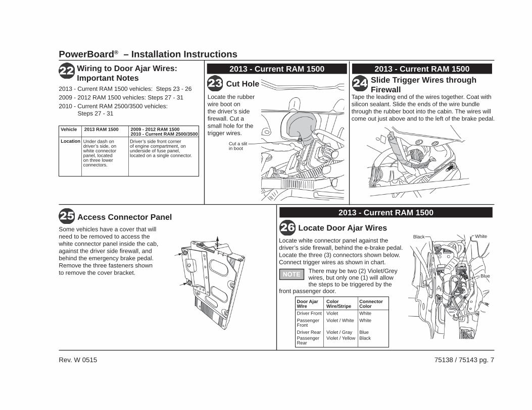
Locate the rubber wire boot on the driver’s side fi rewall. Cut a small hole for the trigger wires.
Tape the leading end of the wires together. Coat with silicon sealant. Slide the ends of the wire bundle through the rubber boot into the cabin. The wires will come out just above and to the left of the brake pedal.
Locate white connector panel against the driver’s side fi rewall, behind the e-brake pedal. Locate the three (3) connectors shown below. Connect trigger wires as shown in chart.
2013 - Current RAM 1500 vehicles: Steps 23 - 262009 - 2012 RAM 1500 vehicles: Steps 27 - 312010 - Current RAM 2500/3500 vehicles: Steps 27 - 31
Cut Hole in Boot Slide Trigger Wires through Firewall
Locate Door Ajar Wires
Wiring to Door Ajar Wires:Important Notes
There may be two (2) Violet/Grey wires, but only one (1) will allow the steps to be triggered by the
front passenger door.
Some vehicles have a cover that will need to be removed to access the white connector panel inside the cab, against the driver side fi rewall, and behind the emergency brake pedal. Remove the three fasteners shown to remove the cover bracket.
Access Connector Panel
Vehicle 2013 RAM 1500 2009 - 2012 RAM 1500 2010 - Current RAM 2500/3500Location Under dash on
driver’s side, on white connector panel, located on three lower connectors.
Driver’s side front corner of engine compartment, on underside of fuse panel, located on a single connector.
2013 - Current RAM 1500 2013 - Current RAM 1500
2013 - Current RAM 1500
Door Ajar Color ConnectorWIre Wire/Stripe ColorDriver Front Violet WhitePassenger Violet / White WhiteFrontDriver Rear Violet / Gray BluePassenger Violet / Yellow BlackRear
Cut a slit in boot
Black White
Blue

PowerBoard® – Installation Instructions
Rev. W 0515 75138 / 75143 pg. 8
Disconnect Fuse Box
Locate the vehicle’s Door Ajar wires on the connector from Step 29.
Wiring
Door Ajar Wires
Color FunctionViolet Driver Door Ajar Switch
SensorViolet / White Passenger Door Ajar Switch
SensorViolet / Gray Driver Rear Door Ajar
Switch SensorViolet / Yellow Passenger Rear Door Ajar
Switch Sensor
Route the purple Wire Harness trigger wires down to the fuse box in front of the battery.
Use a 13mm wrench to remove the fuse box lid and power lead. Depress the release tabs and lift the fuse box to access the bottom.
Route Trigger Wires Route Trigger Wires
Purple Trigger Wire
2009 – 2012 RAM 15002010 – Current RAM 2500/3500
2009 – 2012 RAM 15002010 – Current RAM 2500/3500
2009 – 2012 RAM 15002010 – Current RAM 2500/3500
2009 – 2012 RAM 15002010 – Current RAM 2500/3500
Locate the black connector with the gray latch, labeled “G” on the bottom of the fuse box. Disconnect it.
Cavity Color Function 11 Violet Driver Door Ajar Switch
Sensor 12 Violet / White Passenger Door Ajar
Switch Sensor 16 Violet / Gray Driver Rear Door Ajar
Switch Sensor 14 Violet / Yellow Passenger Rear Door Ajar
Switch Sensor
Door Ajar Wires
Model Year 2011 – Current
Model Year 2009 – 2010
If you do not have this
connector on the bottom of the fuse box follow steps 23-27.
If you do not have this connector on the bottom of the fuse box follow steps 23-27.
Posi-Tap™ Instructions
Insert Tighten
Strip 3/8"Insert and
Tighten
The trigger wires are color coded to match the Door Ajar wires. Use the Posi-Taps™ to splice the trigger wires into the matching Door Ajar wires.Proceed to Step 32.
Splice Trigger Wires into Door Ajar Wires
2013 - Current RAM 1500
PowerBoard® – Installation Instructions
Rev. W 0515 75138 / 75143 pg. 9
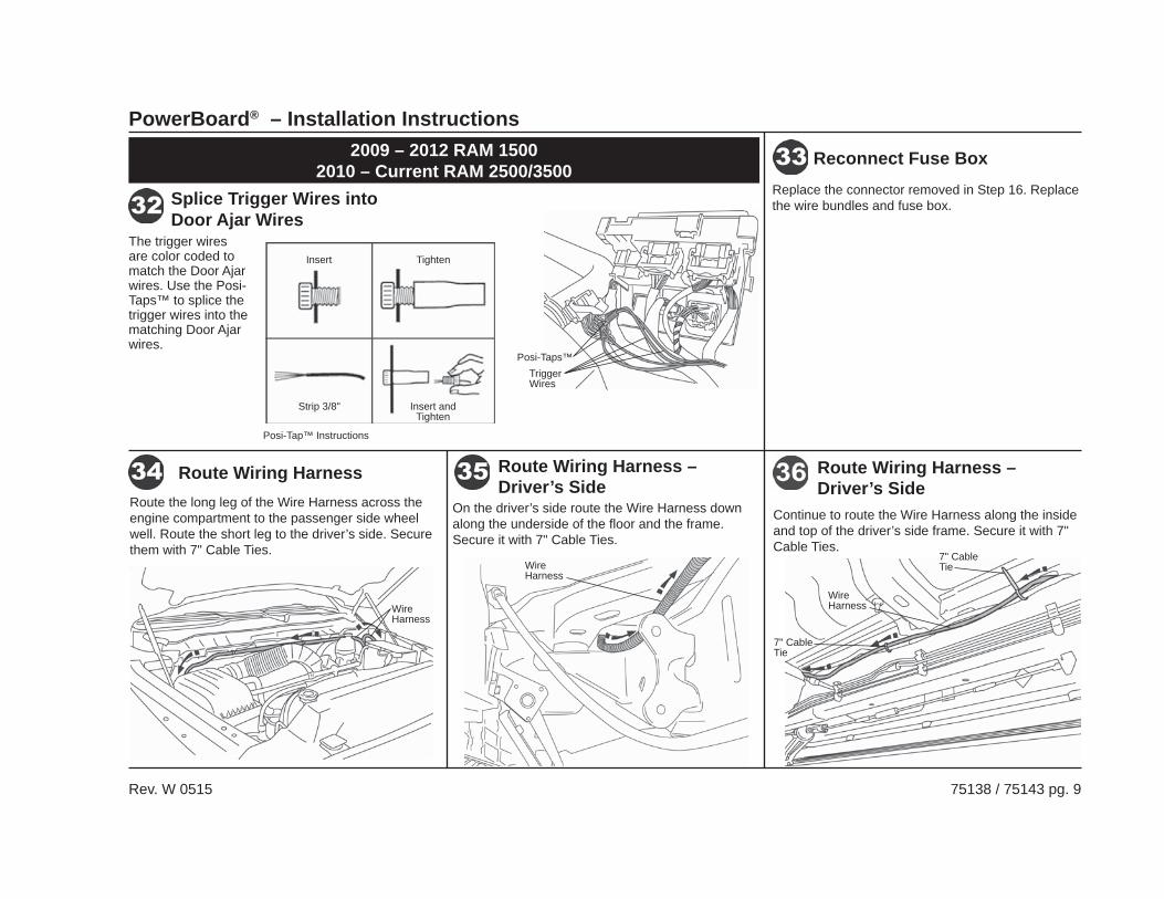
The trigger wires are color coded to match the Door Ajar wires. Use the Posi-Taps™ to splice the trigger wires into the matching Door Ajar wires.
Posi-Tap™ Instructions
Insert Tighten
Strip 3/8" Insert and Tighten
Posi-Taps™Trigger Wires
2009 – 2012 RAM 15002010 – Current RAM 2500/3500
Splice Trigger Wires into Door Ajar Wires
Replace the connector removed in Step 16. Replace the wire bundles and fuse box.
Reconnect Fuse Box
Route the long leg of the Wire Harness across the engine compartment to the passenger side wheel well. Route the short leg to the driver’s side. Secure them with 7" Cable Ties.
Route Wiring Harness
On the driver’s side route the Wire Harness down along the underside of the fl oor and the frame. Secure it with 7" Cable Ties.
Route Wiring Harness – Driver’s Side
Wire Harness
Wire Harness
Continue to route the Wire Harness along the inside and top of the driver’s side frame. Secure it with 7" Cable Ties.
Route Wiring Harness – Driver’s Side
Wire Harness
7" Cable Tie
7" Cable Tie
PowerBoard® – Installation Instructions
Rev. W 0515 75138 / 75143 pg. 10
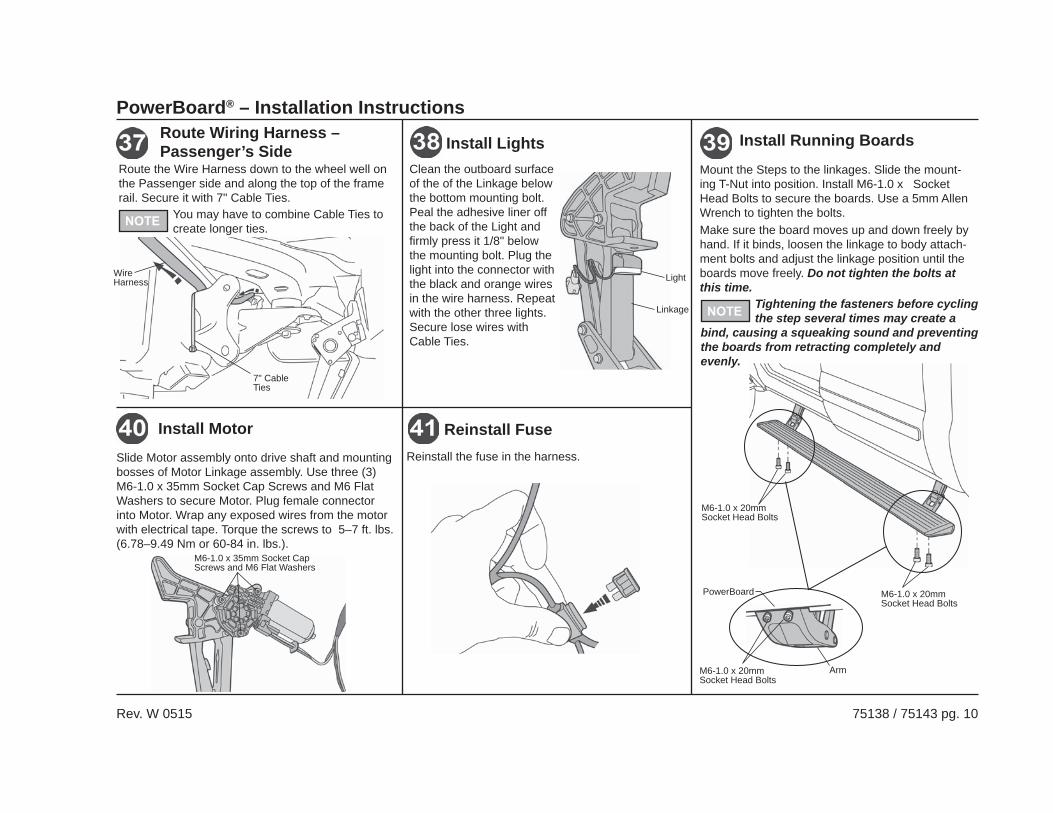
Reinstall the fuse in the harness.
Reinstall FuseSlide Motor assembly onto drive shaft and mounting bosses of Motor Linkage assembly. Use three (3) M6-1.0 x 35mm Socket Cap Screws and M6 Flat Washers to secure Motor. Plug female connector into Motor. Wrap any exposed wires from the motor with electrical tape. Torque the screws to 5–7 ft. lbs. (6.78–9.49 Nm or 60-84 in. lbs.).
Install Motor
M6-1.0 x 35mm Socket Cap Screws and M6 Flat Washers
Mount the Steps to the linkages. Slide the mount-ing T-Nut into position. Install M6-1.0 x Socket Head Bolts to secure the boards. Use a 5mm Allen Wrench to tighten the bolts.Make sure the board moves up and down freely by hand. If it binds, loosen the linkage to body attach-ment bolts and adjust the linkage position until the boards move freely. Do not tighten the bolts at this time.
M6-1.0 x 20mm Socket Head Bolts
Arm
PowerBoard
Install Running Boards
M6-1.0 x 20mm Socket Head Bolts
M6-1.0 x 20mm Socket Head Bolts
Tightening the fasteners before cycling the step several times may create a
bind, causing a squeaking sound and preventing the boards from retracting completely and evenly.
Route the Wire Harness down to the wheel well on the Passenger side and along the top of the frame rail. Secure it with 7" Cable Ties.
You may have to combine Cable Ties to create longer ties.
Route Wiring Harness – Passenger’s Side
7" Cable Ties
Wire Harness
Clean the outboard surface of the of the Linkage below the bottom mounting bolt. Peal the adhesive liner off the back of the Light and fi rmly press it 1/8" below the mounting bolt. Plug the light into the connector with the black and orange wires in the wire harness. Repeat with the other three lights. Secure lose wires with Cable Ties.
Install Lights
Light
Linkage
PowerBoard® – Installation Instructions
Rev. W 0515 75138 / 75143 pg. 11
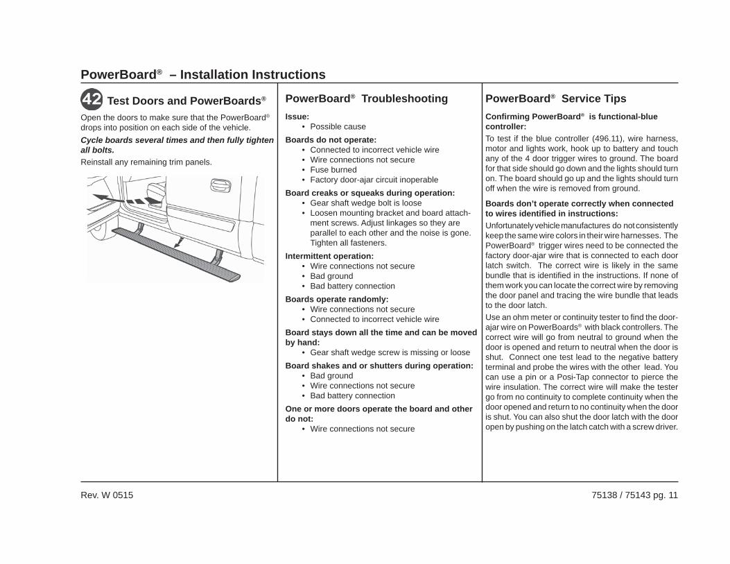
Open the doors to make sure that the PowerBoard® drops into position on each side of the vehicle.Cycle boards several times and then fully tighten all bolts.Reinstall any remaining trim panels.
Test Doors and PowerBoards®
Issue:• Possible cause
Boards do not operate:• Connected to incorrect vehicle wire• Wire connections not secure• Fuse burned• Factory door-ajar circuit inoperable
Board creaks or squeaks during operation:• Gear shaft wedge bolt is loose• Loosen mounting bracket and board attach-
ment screws. Adjust linkages so they are parallel to each other and the noise is gone. Tighten all fasteners.
Intermittent operation:• Wire connections not secure• Bad ground• Bad battery connection
Boards operate randomly:• Wire connections not secure• Connected to incorrect vehicle wire
Board stays down all the time and can be moved by hand:
• Gear shaft wedge screw is missing or looseBoard shakes and or shutters during operation:
• Bad ground• Wire connections not secure• Bad battery connection
One or more doors operate the board and other do not:
• Wire connections not secure
PowerBoard® TroubleshootingConfirming PowerBoard® is functional-blue controller:To test if the blue controller (496.11), wire harness, motor and lights work, hook up to battery and touch any of the 4 door trigger wires to ground. The board for that side should go down and the lights should turn on. The board should go up and the lights should turn off when the wire is removed from ground.
Boards don’t operate correctly when connected to wires identifi ed in instructions:Unfortunately vehicle manufactures do not consistently keep the same wire colors in their wire harnesses. The PowerBoard® trigger wires need to be connected the factory door-ajar wire that is connected to each door latch switch. The correct wire is likely in the same bundle that is identifi ed in the instructions. If none of them work you can locate the correct wire by removing the door panel and tracing the wire bundle that leads to the door latch.Use an ohm meter or continuity tester to find the door-ajar wire on PowerBoards® with black controllers. The correct wire will go from neutral to ground when the door is opened and return to neutral when the door is shut. Connect one test lead to the negative battery terminal and probe the wires with the other lead. You can use a pin or a Posi-Tap connector to pierce the wire insulation. The correct wire will make the tester go from no continuity to complete continuity when the door opened and return to no continuity when the door is shut. You can also shut the door latch with the door open by pushing on the latch catch with a screw driver.
PowerBoard® Service Tips
PowerBoard® – Installation Instructions
Rev. W 0515 75138 / 75143 pg. 12
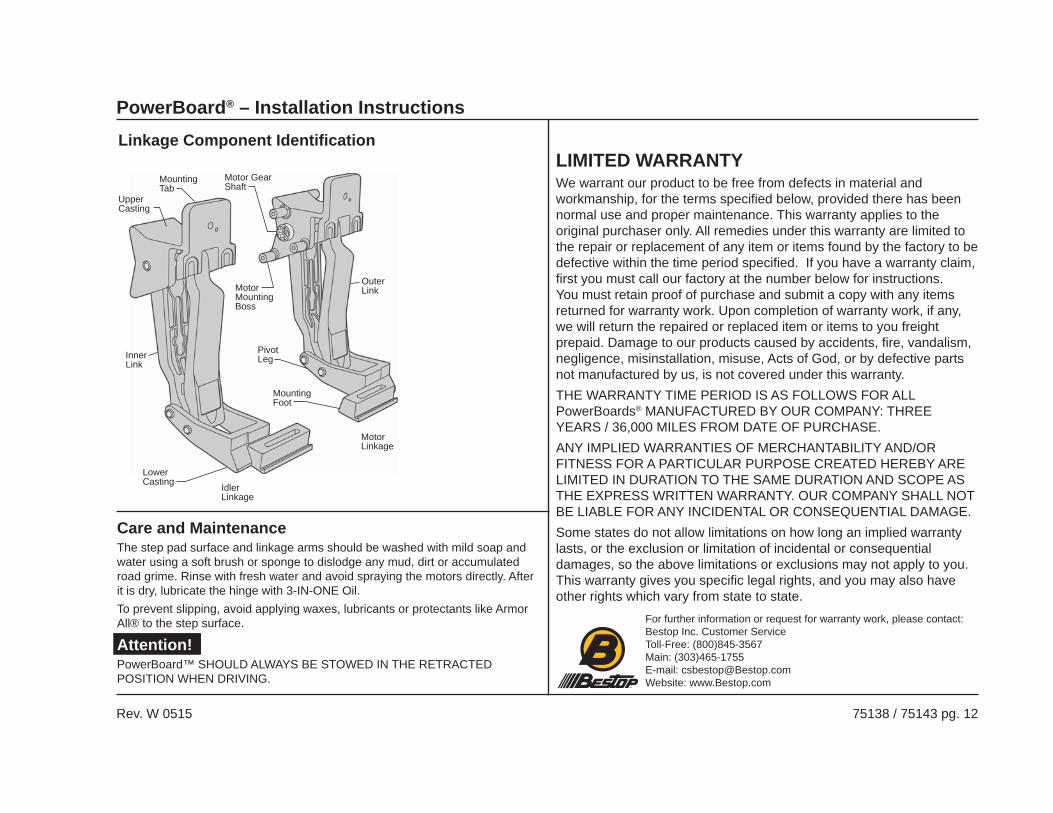
Linkage Component Identifi cation
Motor Gear Shaft
Motor Mounting Boss
Mounting Tab
Upper Casting
Outer Link
Inner Link
Lower Casting
Mounting Foot
Motor Linkage
Idler Linkage
Pivot Leg
LIMITED WARRANTYWe warrant our product to be free from defects in material and workmanship, for the terms specifi ed below, provided there has been normal use and proper maintenance. This warranty applies to the original purchaser only. All remedies under this warranty are limited to the repair or replacement of any item or items found by the factory to be defective within the time period specifi ed. If you have a warranty claim, fi rst you must call our factory at the number below for instructions. You must retain proof of purchase and submit a copy with any items returned for warranty work. Upon completion of warranty work, if any, we will return the repaired or replaced item or items to you freight prepaid. Damage to our products caused by accidents, fi re, vandalism, negligence, misinstallation, misuse, Acts of God, or by defective parts not manufactured by us, is not covered under this warranty. THE WARRANTY TIME PERIOD IS AS FOLLOWS FOR ALL PowerBoards® MANUFACTURED BY OUR COMPANY: THREE YEARS / 36,000 MILES FROM DATE OF PURCHASE.ANY IMPLIED WARRANTIES OF MERCHANTABILITY AND/OR FITNESS FOR A PARTICULAR PURPOSE CREATED HEREBY ARE LIMITED IN DURATION TO THE SAME DURATION AND SCOPE AS THE EXPRESS WRITTEN WARRANTY. OUR COMPANY SHALL NOT BE LIABLE FOR ANY INCIDENTAL OR CONSEQUENTIAL DAMAGE.Some states do not allow limitations on how long an implied warranty lasts, or the exclusion or limitation of incidental or consequential damages, so the above limitations or exclusions may not apply to you. This warranty gives you specifi c legal rights, and you may also have other rights which vary from state to state.
For further information or request for warranty work, please contact:Bestop Inc. Customer ServiceToll-Free: (800)845-3567Main: (303)465-1755E-mail: [email protected]: www.Bestop.com
Care and MaintenanceThe step pad surface and linkage arms should be washed with mild soap and water using a soft brush or sponge to dislodge any mud, dirt or accumulated road grime. Rinse with fresh water and avoid spraying the motors directly. After it is dry, lubricate the hinge with 3-IN-ONE Oil.To prevent slipping, avoid applying waxes, lubricants or protectants like Armor All® to the step surface.
Attention!PowerBoard™ SHOULD ALWAYS BE STOWED IN THE RETRACTED POSITION WHEN DRIVING.


