
VEL TECH HIGH TECH DR. RANGARAJAN DR.SAKUNTHALA ENGINEERING COLLEGE
AVADI, CHENNAI
DEPARTMENT OF CIVIL ENGINEERING
YEAR/SEM : III / V
SUBJECT CODE/TITLE : CE 8351/ SURVEYING
FACULTY NAME : RAGHUL RAJ B
UNIT-1
FUNDAMENTALS OF CONVENTIONAL SURVEYING AND LEVELLING
DEFINITION OF SURVEYING
Surveying is the Art of determining the relative position on above or beneath the Surface of the earth
by means of direct or indirect measurements of distance,direction and elevation.
It also includes the art of establishing points by predetermined angular & Linear Measurements.
CLASSIFICATION OF SURVEYING
i)PLANE SURVEYING
Plane Surveying is defined as the divison of Surveying in which all the survey works are carried based
on the assumption that,the surface of earth is a plane and curvature of the earth is Ignored.
In Dealing with the plane Surveying,plane geometry and Trignometry are only required.
The Surveys having an area of about 260km2 may only be treated as plane surveys.
USES:
Plane Surveys which generally include the area upto 260km2 are carried out for engineering
projects,on large scales to determine relative positions of individual features on the earths surface.
Plane Surveys are used to prepare the layout for highways,canals,railways,construction of various
features etc.
ii)GEODETIC SURVEYING:
The Surveys in which curvaqture of the earth is taken into account and higher degree of accuracy
required is called geodetic surveying.
USES:
Geodetic Surveys carried out with higher degree of accuracy to provide the spaced control points on
the earth surface.
It Requires advanced instruments.In India Surveys carried out by the department of survey of india
under the control and direction of surveyor general of India.

SURVEYING
Plane Surveying Geodetic Surveying
CLASSIFICATION BASED ON
PURPOSE OF SURVEYING NATURE OF FIELD METHODS ADOPTED INSTRUMENT USED
i.Engineering Surveys 1.Engineering Surveys 1.Triangulation 1.Chain Surveying
ii.Military or Defence a.Topographical 2.Traversing 2.Compass Surveying
iii.Mine Surveys b.Cadastral Survey 3.Levelling 3.Plane Table Surveying
iv.Geological or c.City Survey 4. Tacheometry 4.Levelling Surveying
Geographical Surveys 2.Marine Survey & 5.Theodolite Surveying
v.Archaeological Surveys 3.Astronomical Survey 6.Total Station
vi.Route and Location Surveys

CLASSIFICATION BASED ON PURPOSE OF SURVEYING
i) ENGINEERING SURVEYS
The Determination of quantities or to afford sufficient data for the designing of engineering
works such as roads and reservoirs,or those connected with sewage disposal or water supply
II) MILITARY OR DEFENCE SURVEY
This is used for determining points of strategic importance.
III) MINE SURVEY
This is used for the exploring mineral wealth
OBJECTS OF THE SURVEY
To Calculate The Distances Between Various Points And To Calculate The Levels Of Various
Points
To check out the alignment of various engineering structures.
To calculate the areas and volumes,involved in the various engineering projects.
To Prepare the plans and maps sections and profile,contours ects.
To Measure and to determine the relative positions of the various objects of the earths surface
EQUIPMENT AND ACCESSORIES FOR CHAINING AND RANGING:
(i)Chain
(ii)Arrows
(iii) Pegs
(iv)Surveyors' band
(v) Ranging rods and ranging poles
(vi) Offset rods
(vii) Laths
(viii) Whites
(ix) Plumb bobs and
(x) Line ranger.
(i)CHAIN
The Chain Is Made Up Of Steel Wire Which Is Divided Into Links And Togs (Rings) To Facilitate Folding.
It Is Sometimes Used As A Unit Of Measurement
It Has Brass Handles At Both Ends For Easy Handling. The Link Is 0.2m Or 200mm In Diameter.
The Length Is 20m Or 30m.
(ii) ARROWS:
Arrows are made of steel wire of diameter 4mm and their ends are bent into a circle where red cloth is
tied to facilitate visibility. They are used for showing points on the ground.
iii)PEGS
Pegs are made of wood 40mm square by 50cm long and are used for permanently marking positions
during survey

iv)SURVEYORS' BAND
The surveyor’s band is made of a steel strip which is rolled into a metal frame with a winding handle.
It is 30m, 50m or 100m long. Is used in projects where more accuracy measurement is required.
(v) RANGING RODS AND RANGING POLES:
A ranging rod is a surveying instrument used for marking the position of stations and for sightings of
those stations as well as for ranging
Ranging poles are used to mark areas and to set out straight lines on the field. They are also used to
mark points which must be seen from a distance, in which case a flag may be attached to improve the
visibility.
(vi) OFFSET RODS
These rods are also similar to ranging rods and they are 3 m long. They are made up of hard wood
and are provided with iron shoe at one end.
A hook or a notch is provided at other end. At height of eye, two narrow slits at right angles to each
other are also provided for using it for setting right angles.
(vii) LATHS
Laths are 0.5 to 1.0 m long sticks of soft wood. They are sharpened at one end and are painted with white
or light colours. They are used as intermediate points while ranging or while crossing depressions.
(viii) WHITES
Whites are the pieces of sharpened thick sticks cut from the nearest place in
the field. One end of the stick is sharpened and the other end is split. White papers are inserted in the
split to improve the visibility. Whites are also used for the same purpose as laths.
(IX) PLUMB BOBS:
In measuring horizontal distances along sloping ground plumb bobs are used to transfer the position to
ground.They are also used to check the verticality of ranging poles.
(X) LINE RANGER:
It is an optical instrument used for locating a point on a line and hence useful for ranging. It consists
of two isosceless prisms placed one over the other and fixed in an instrument with handle.
METHODS OF RANGING
i)Direct Ranging
ii)Indirect Ranging
i)DIRECT RANGING:
Direct Ranging is done when the two ends of the survey lines are intervisible.

ii)INDIRECT RANGING
It is done when both the ends of the survey line are not intervisible either due to Long distance
between them.
COMPASS SURVEYING
Compass surveying is a type of surveying in which the directions of surveying lines are determined
with a magnetic compass, and the length of the surveying lines are measured with a tape or chain or
laser range finder.
i)Prismatic Compass
ii)Surveyor Compass
i)PRISMATIC COMPASS
A prismatic compass is a navigation and surveying instrument which is extensively used to
find out the bearing of the traversing and included angles between them, waypoints (an endpoint of
the course) and direction.
ii)SURVEYOR COMPASS
Surveyor’s compass consists of a circular brass box containing a magnetic needle which swings
freely over a brass circle which is divided into 360 degrees. The horizontal angle is measured using a
pair of sights located on north – south axis of the compass. They are usually mounted over a tripod
and leveled using a ball and socket mechanism.
BASIC PRINCIPLE OF COMPASS SURVEY
The Principle of Compass Survey is Traversing; which involves a series of connected lines the
magnetic bearing of the lines are measured by prismatic compass and the distance (lengths) of the are
measured by chain.
BEARING
The Bearing of a line is the Horizontal Angle which it makes with a reference line(meridian)
depending upon the Meridian.
TYPES OF BEARING
i. True Bearing
ii. Magnetic Bearing
iii. Arbitrary Bearing
i)TRUE BEARING
True Bearing of a line is the horizontal angle which it makes with the true meridian through one of the
extremities of the line.

ii) MAGNETIC BEARING
The Magnetic Bearing of a line is the horizontal angle which it makes with the magnetic meridian
passing through one of the extremities of the line.
iii)ARBITRARY BEARING
Arbitrary Bearing of a line is the horizontal angle which it makes with any arbitrary meridian passing
through one of the Extremities.
LEVELLING
Levelling is a branch of surveying, the object of which is:
To Find The Elevations Of Given Points With Respect To A Given Or Assumed Datum, And
To Establish Points At A Given Or Assumed Datum.
BASIC PRINCIPLE OF LEVELING
The fundamental principle of leveling lies in finding out the separation of level lines passing
through a point of known elevation (B.M.) and that through an unknown point (whose elevation is
required to be determined).
METHODS OF LEVELLING
i)BAROMETRIC LEVELLING
Barometric Leveling. Barometer is an instrument used to measure atmosphere at any altitude. So, in
this method of leveling, atmospheric pressure at two different points is observed, based on which the
vertical difference between two points is determined.
ii)DIRECT LEVELLING
It is the most commonly used method of leveling. In this method, measurements are observed directly
from leveling instrument.
iii) TRIGONOMETRIC LEVELING
The process of leveling in which the elevation of point or the difference between points is measured
from the observed horizontal distances and vertical angles in the field is called trigonometric leveling.
SOURCES OF ERRORS IN LEVELLING
There are following types of Errors in Leveling :-
1. Instrumental Errors
2. Collimation Error
3. Error due to Curvature & Refraction
4. Other Errors
1.INSTRUMENTAL ERRORS & CORRECTION
1. Collimation error
Correction: Check before use and equalise sights.
2. Under sensitive bubble.
3. Errors in staff graduation
Correction: Check
4. Loose tripod head.
5. Telescope not parallel to bubble tube
Correction: Permanent adjustment.
6. Telescope not at right angles to the vertical axis
Correction: Permanent adjustment
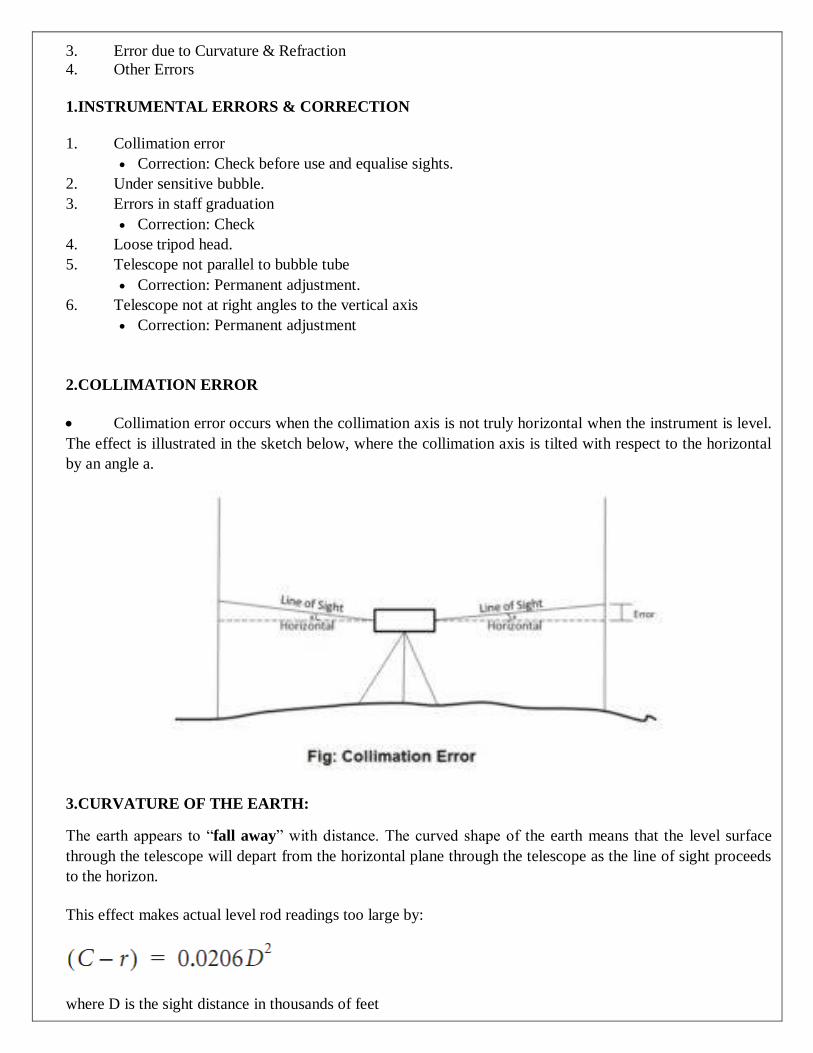
2.COLLIMATION ERROR
Collimation error occurs when the collimation axis is not truly horizontal when the instrument is level.
The effect is illustrated in the sketch below, where the collimation axis is tilted with respect to the horizontal
by an angle a.
3.CURVATURE OF THE EARTH:
The earth appears to “fall away” with distance. The curved shape of the earth means that the level surface
through the telescope will depart from the horizontal plane through the telescope as the line of sight proceeds
to the horizon.
This effect makes actual level rod readings too large by:
where D is the sight distance in thousands of feet

PART - A (2 marks)
1. Describe the principle of surveying. (AUC Apr/May 2011) (AUC Nov/Dec 2011)
The fundamental principles upon which the surveying is being carried out are
Working from whole to part.
After deciding the position of any point, its reference must be kept from at least two
permanent objects or stations whose positions have already been well defined.
222. 2.What is the purpose of an optical square? (AUC Apr/May 2011) (AUC May/June 2012)
It is more accurate than the cross staff and it can be used for locating objects situated at larger
distances. It is small and compact hand instrument and works on the principle of reflection.
3.What do you mean by reciprocal ranging? (AUC Apr/May 2010)
When the end stations are not intervisible due to high ground or a hill or if the
ends are too long. In such cases, intermediate points can be fixed on the survey line by a
process known as Reciprocal ranging or Indirect ranging.
4. What do you mean by scale in surveying? (AUC Nov/Dec 2011)
Scale is a fixed ratio that every distance on the plan bears with corresponding distance on the ground.
For example: 1cm = 10m.
5. Define conditioned triangles. (AUC Nov/Dec 2010)
The accuracy of a triangulation system, in which any error in angular measurement has a
minimum effect upon the computed lengths, is known as well-conditioned triangle.
6. Explain the range of reciprocal ranging. (AUC May/June 2013)
The vision ranging and line ranger can be adopted only when the end stations are inter-
visible. The line of sight between two stations is obstructed by natural or man-made objects or not
clearly visible. Under such conditions, indirect or reciprocal ranging is applicable.
7. What do you mean by plane surveying? (AUC May/June 2013)
Plane surveying is a process of surveying in which the portion of the earth being
surveyed is considered a plane. In this training manual, we used in plane surveying rather
than those used in geodetic surveying.
8. What is meant by geodetic surveying? (AUC Nov/Dec
2012)
Geodetic surveying is a process of surveying in which the shape and size of the earth are
considered. The methods used in geodetic surveying are beyond the scope of this training
manual.
9.Explain the Methods Of Ranging.
i) Direct Ranging
ii) Indirect Ranging
i) DIRECT RANGING :
Direct Ranging is done when the two ends of the survey lines are intervisible.
ii) INDIRECT RANGING:
It is done when both the ends of the survey line are not intervisible either due to Long
distance between them.
10.Define True Meridian. (AUC Nov/Dec 2012) (AUC Nov/Dec 2010)
True Meridian is defined as the line Joining the Geographical North and South
Pole.
True Meridian at various Places are not Equal
11.What is Magnetic Meridian ? (AUC May/Jun 2012)
Magnetic Meridian is defined as the Longitudinal axis indicated by the freely
Suspended,properly balanced Magnetic Needle.
It Does not coincide with the true Meridian except in certain places during the year
12.What are the types of corrections to be applied? (AUC Nov/Dec 2014)
Correction for Length.
Correction for Temperature.
Correction for Pull.
Correction for Sag.
Correction for Slope.
What Is Two Point Problem? (AUC May/Jun
2013)
Two Point Problem is defined as the process of locating the plane table on the
sheet by sighting two well defined Points And its locations are already plotted on the Paper.
14.Define Three Point Problem? (AUC May/Jun 2013)
Two Point Problem is defined as the process of locating the plane table on the sheet by

sighting two well defined Points And its locations are already plotted on the Paper.
15.Distinguish Between Angle And Bearing. (AUC May/Jun 2012)
An Angle is defined as the deviation of one straight line with respect to the other one.
Bearing is defined as the angle or Inclination of a survey Line with respect to the north -
South Direction.
16.What are the Sources Of Local Attraction?
Magnetic Materials such As magenetic Rocks,iron Ores,Electrical cables etc..are sources of
Local Attraction.
17.Name the different ways of classification of Surveying.
Classification Of Survey is based on
i. Purpose of Surveying
ii. Nature of the field
iii. Methods employed
iv. Instruments Used
18.How do you fix a point from control points(or a Survey Line)?
The position of a third point can be located from control points by anyone of the following Ways.
1.Two linear measurement
2.Two Angular Measurement
3.One linear measurement & one Angular Measurement.
19.Write the equation for correction of temperature
Temperature correction
Ct = α(Tm-To)L
α -coefficient of thermal expansion
Tm -mean temperature during measurements
To -normal temperature at stanrardlization
L-measured length of the line.
20.What circumstances in which reciprocal ranging is used ?(or) When do you require
ranging? (or) Explain the use of reciprocal ranging?
i. Reciprocal ranging is the method of indirect ranging and it is adopted when the
ii. Two end stations are move to raised grounds
21.In a chain how will you set out a right angle?
i) Cross-staff is the instrument used to locate the intersection point of a particular offset on a chain
line.
ii)Optical Squares are also like cross-staves used for setting out the right angles in change-surveying.
22.What are the Instruments Used for chain Surveying?
1.Chain
2.Tape
3.Ranging Rods
4.Offset Rods
5.Plumb Bob
6. Pegs
7.Cross-staff
8.Optical Square
9.Arrows
23.Write a difference between a map & Plan.
S.No. Factor Map Plan
1. Sclae Maps are the Drawing
with Small Scale
Plans are the drawing
with Large Scale
2. Details A map generally deals
about the
Geographical Details
A Plan deals with the
details of the
engineering
Structures.
24.List out various Classification of surveying.
i. Chain Surveying.
ii. Compass Surveying.
iii. Plane table Surveying.
iv. Theodolite Level Surveying.
v. Tacheometric Surveying.
vi. Total station Surveying.
PART-B
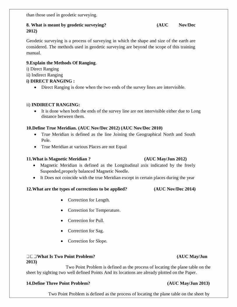
1.A survey line ABC crossing a river angles cuts its banks at B and C. To determine the width
BC of the river. The following operation was carried out. A point E was established on the
perpendicular BE such that angle CEF is a right angle where F is a point on the survey line. If
the chainage of F and B are respectively 1200 m and 1320 m and the distance EB is 90
m.Calculate the width of the river and also the chainage of C. (AUC Apr/May 2011)
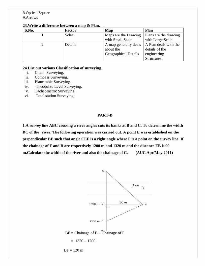
BF = Chainage of B – Chainage of F
= 1320 – 1200
BF = 120 m

From ∆ EBF,
tan BEF=120/90 = 1.33
BEC CEF BEF
= 90O - 53O 3’
BEC 36O 57’
From ∆ BEC,
tan (36O 57’) = CB/BE = CB/90
CB = 90 X tan (36O 57’)
CB = 67.69 m
The width of the river, CB = 67.69 m
Chainage of C = chainage of B + width of the river
= 1320 + 67.69
Chainage of C = 1387.69 m
2.Explain the methods of chaining while there are obstacles such as building or river. (AUC Nov/Dec
2011) (AUC May/June 2012) (AUC Apr/May 2010).
In this case it is required to prolong the chain line beyond the obstacle and to find the distance across it. In this
case the typical obstacle is a building. One of the following two methods may be adopted.
FIRST METHOD:
On one side of the chain line AB, two points P and Q are selected. Perpendiculars of equal length PP’ and
QQ’ are erected. The line P’Q’ is extended till the building is passed. On the extended line, two points R and
S are selected. The perpendicular at R and S are so erected such that RR’ = SS’ = QQ’ = PP’. then the
points P’, Q’, R’ and S’ will lie on the same line. Then Q’R = QR and the distance Q’R’ is measured to
set QR, then the line is extended.
SECOND METHOD:
This method is also equally applicable for this condition. Two points P and Q on the chain line AB are
selected on the one side of the chain line. A perpendicular QR is erected at Q such that QR = PR. Points P and
R are jointed and extended upto S. A perpendicular SV is set at S such that PS = SV. On the line SV a point T
is marked such that ST = SR. with V as centre and radius equal to QR cut an arc such that PQ = QR = VT =
UT. Then U and V are on the chain line AB. The distance RT is measured. Thus the obstructed length, QU =
RT.

3.Determine the sag correction for a 30 m steel tape under a pull of 80 N in 3 bays of 10 m each. The
area of the cross section of the tape is 8 mm2 and the unit weight of steel may be taken as 77 kN/m3.
(AUC Nov/Dec 2011)
Solution:
Given:
L = 30 m; n = 3; P = 80 N; Area = 8 mm2 = 8 x 10⁻⁶ m2; γ = 77 kN/m3
Total weight of tape = 77 x 103 x 8 x 10-6 x 10 = 6.16 N
Cs = LW 2 / 24n 2 P 2
=10 X 6.16 2 /24 X 1 2 X 80 2
= 0.00247 m
Cs = 3 x 0.00247 = 0.00741 m
True length = 30 – 0.00741
True length = 29.993 m
4. Explain the field and office work in chain surveying? (AUC May/June 2013)
Field and Office work:
The practice of surveying actually boils down to fieldwork and office work. The Fieldwork
Consists Of Taking Measurements, Collecting Engineering Data, And Testing Materials. The Office
Work Includes Taking Care Of The Computation And Drawing The Necessary Information For The
Purpose Of The Survey.
Field Work:
Field work is of primary importance in all types of surveys. To be a skilled surveyor, you
must spend a certain amount of time in the field to acquire needed experience.
The study of this training manual will enable you to understand the underlying theory of
surveying, the instruments and their uses, and the surveying methods.
However, a high degree of proficiency in actual surveying, as in other professions,
depends largely upon the duration, extent, and variation of your actual experience.
You should develop the habit of STUDYING the problem thoroughly before going into
the field, you should know exactly what is to be done; how you will do it; why you prefer
a certain approach over other possible solutions; and what instruments and materials you
will need to accomplish the project.
It is essential that you develop SPEED and CONSISTENT ACCURACY in all your
fieldwork. This means that you will need practice in handling the instruments, taking
observations and keeping field notes, and planning systematic moves.
It is important that you also develop the habit of CORRECTNESS. You should not
accept any measurement as correct without verification. Verification, as much as
possible, should be different from the original method used in measurement.
The precision of measurement must be consistent with the accepted standard for a
particular purpose of the survey. Fieldwork also includes adjusting the instruments and
caring for field equipment.
Do not attempt to adjust any instrument unless you understand the workings or functions
of its parts. Adjustment of instruments in the early stages of your career requires close
supervision from a senior EA.
Office Work:
Office work in surveying consists of converting the field measurements into a usable format.The
conversion of computed, often mathematical, values may be required immediately to continue the
work, or it may be delayed until a series of field measurements is completed.
Although these operations are performed in the field during lapses between measurements, they can
also be considered office work. Such operations are normally done to save time.
Special equipment, such as calculators, conversion tables, and some drafting equipment is used in
most office work. In office work, converting field measurements (also called reducing) involves the
process of computing, adjusting, and applying a standard rule to numerical values.
5.Explain how you will conduct chain survey to measure a land parcel in agriculture field.
(AUC May/June 2013)
Using chaining and ranging the distance between two points can be measured.The
instruments required are chain, arrows, ranging rods, pegs and hammers.
Procedures:
First mark a straight line of a standard length on a flat firm ground. The two end points A and B are
selected on a survey line which is to be measured.

A ranging rod is erected at the point B, while the surveyor stands with another rod at point A. A rod is
established at a point in line with AB at a distance not greater than one chain length from A.
The surveyor at A then signals the assistant to move transverse to the chain line till he is line with A
and B. Similarly other intermediate points can be established.
Then by using chain, the distance is measured. To find the pacing length, we should walk along the
chain line and it is found from pacing length.
Pacing length = Distance between the points/No of steps
The distance between two points = (No of arrow x Nominal length +Fractional length) m
The distance between two points can be calculated and also same procedure is used to find the other
side of the line. The finally land parcel of agricultural field is measured
UNIT II
THEODOLITE AND TACHEOMETRIC SURVEYING
THEODOLITE
A theodolite is an instrument which is used primarily to measure angles, both horizontal and vertical.
It is also used for many other subsidiary work during surveying such as setting up of intermediate
points between inter visible points, establishment of inter visible points, prolonging a line, laying out
traverse etc.
A modern theodolite consists of a movable telescope mounted within two perpendicular axes the
horizontal or trunnion axis, and the vertical axis. When the telescope is pointed at a target object, the
angle of each of these axes can be measured with great precision.
TYPES OF THEODOLITE
There are different types of theodolite available. It may be classified into three broad categories.
Vernier or Transit Theodolite
Digital Theodolite
Total Station
TRANSIT THEODOLITE
A Transit Theodolite Is One In Which The Telescope Can Be Revolved Through A Complete
Revolution About Its Horizontal Axis In A Vertical Plane.
DIGITAL THEODOLITE
Digital theodolite is a modern engineering instrument for measuring both horizontal and vertical
angles, It is a key tool in surveying and engineering work.
The theodolite consists of a telescope movable within two perpendicular axes- the horizontal axis, and
the vertical axis.When the telescope is pointed at a desired object, the angle of each of these axes can be
measured with great precision.
TOTAL STATION
A total station or TST (total station theodolite) is an electronic/optical instrument used
for surveying and building construction.
The total station is an electronic theodolite (transit) integrated with an electronic distance
measurement (EDM) to read slope distances from the instrument to a particular point, and an on-board
computer to collect data and perform advanced coordinate based calculations.
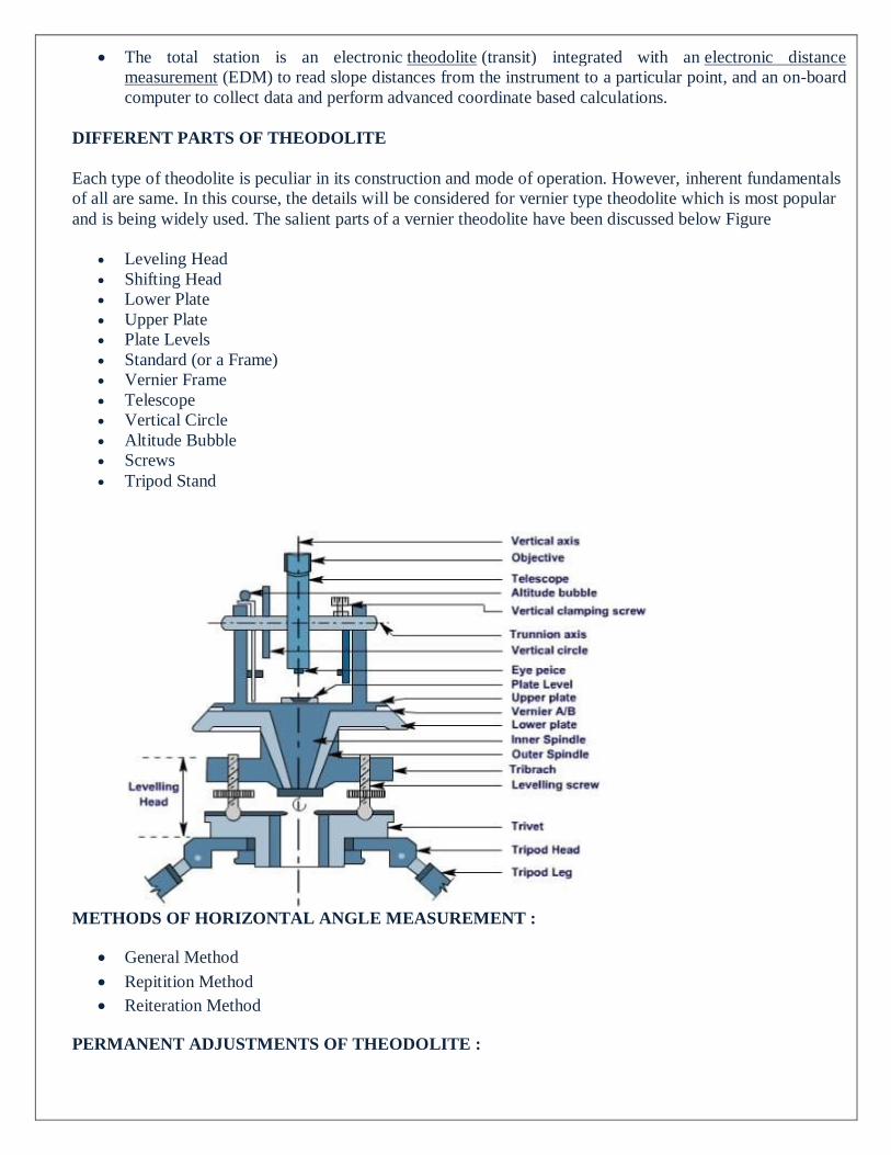
DIFFERENT PARTS OF THEODOLITE
Each type of theodolite is peculiar in its construction and mode of operation. However, inherent fundamentals
of all are same. In this course, the details will be considered for vernier type theodolite which is most popular
and is being widely used. The salient parts of a vernier theodolite have been discussed below Figure
Leveling Head
Shifting Head
Lower Plate
Upper Plate
Plate Levels
Standard (or a Frame)
Vernier Frame
Telescope
Vertical Circle
Altitude Bubble
Screws
Tripod Stand
METHODS OF HORIZONTAL ANGLE MEASUREMENT :
General Method
Repitition Method
Reiteration Method
PERMANENT ADJUSTMENTS OF THEODOLITE :

The permanent adjustments are made to establish the relationship between the fundamental lines of the
theodolite and , once made , they last for a long time. They are essential for the accuracy of
observations.
The permanent adjustments in case of a transit theodolites are :-
i) Adjustment of Horizontal Plate Levels.
The axis of the plate levels must be perpendicular to the vertical axis.
ii) Collimation Adjustment.
The line of collimation should coincide with the axis of the telescope and the axis of the
objective slide and should be at right angles to the horizontal axis.
iii) Horizontal axis adjustment.
The horizontal axis must be perpendicular to the vertical axis.
iv) Adjustment of Telescope Level or the Altitude Level Plate Levels.
The axis of the telescope levels or the altitude level must be parallel to the line of
collimation.
v) Vertical Circle Index Adjustment.
The vertical circle vernier must read zero when the line of collimation is horizontal.
TEMPORARY ADJUSTMENTS OF THEODOLITE
The temporary adjustments are made at each set up of the instrument before we start taking
observations with the instrument. There are three temporary adjustments of a theodolite:-
i)Centering.
ii)Levelling.
iii)Focussing.
STADIA CONSTANT
The distance is chosen so that there is a fixed, integer ratio between the distance observed between the
marks and the distance from the telescope to the measuring device observed. This is known as the stadia
constant or stadia interval factor. For example, a typical stadia mark pair are set so that the ratio is 100.
ANALYTIC LENS
It is a special convex lens, fitted in between the object glass and eyepiece, at a fixed distance from the
object glass, inside the telescope of a tacheometer. The function of the anallactic lens is to reduce the stadia
constant to zero.
Thus, when tacheometer is fitted with anallactic lens, the distance measured between instrument
station and staff position (for line of sight perpendicular to the staff intercept) becomes directly proportional
to the staff intercept. Anallactic lens is provided in external focusing type telescopes only
TACHEOMETER
A tacheometer is similar to an ordinary transit theodolite fitted with stadia wires in addition to the
central cross-hairs.
As accuracy and speed are necessary, the telescope fitted with a tacheometer must fulfill additional
requirements. Also, the vertical circle should be more refined.
The telescope of the tacheometer is usually longer than that of the Ordinary theodolite and has a higher
power of magnification.
The object glass is of greater diameter, and the lens system is of better quality. The magnification
power should not be less than 20-25.
The effective aperture should not be less than 3.5-4.5 cm in diameter facilitating the obtaining of a
bright image.
The multiplying constant of the instrument (f/I) is generally kept as 100. Sometimes an additional pair
cross-hairs is provided such that the multiplying constant (f/I) is 50.
TACHEOMETRY SURVEY
Tachometry is a branch of angular surveying in which A horizontal & vertical distance is of
points are obtain by optical means as suppose to ordinary slow process of measure by tape
chain.
This methods is very rapid & convenient. All though the accuracy of tachometry is low it is
best adopted in obstructed such as steep & broken ground stretches of water etc which make
drawn age difficult.
They primary object of tachometry is the preparation of contour maps are plans required with
both horizontal & vertical measurements also accuracy improvement it provides at check an
distance measure with tape.
At the instruments a normally transit theodalite pitted with stadia diaphragm is generally used
for tachometry survey. A stadia diaphragmessentially consist of one stadia hair above on the
other an equal distance below the horizontal cross hair. Telescope is used in stadia surveying are
of 3 types :-
a. Simple external focusing telescope
b. External focusing analytic
c. Internal focusing telescope
METHODS OF TACHOMETRIC SURVEY:
(1) Stadia system
(2) Tangential system
(1) STADIA SYSTEM OF TACHEOMETRY
In the stadia system, the horizontal distance to the staff Station from the instrument station and the elevation
of the staff station concerning the line of sight of the instrument is obtained with only one observation from
the instrument Station.
In the stadia method, there are mainly two systems of surveying.
(1) fixed hair method and,
(2) movable hair method.
(i) FIXED HAIR METHOD:

In the fixed hair method of tacheometric surveying, the instrument employed for taking observations
consist of a telescope fitted with two additional horizontal cross hairs one above and the other below
the central hair.
These are placed equidistant from the central hair and are called stadia hairs.
When a staff is viewed through the telescope, the stadia hairs are seen to intercept a certain length of
the staff and this varies directly with the distance between the instrument and the stations.As the
distance between the stadia hair is fixed, this method is called the “fixed hair method.”
(ii) MOVABLE HAIR METHOD
In the movable Hair method of tacheometric surveying, the instrument used for taking observations
consist of a telescope fitted with stadia hairs which can be moved and fixed at any distance from the central
hair (within the limits of the diaphragm).
The staff used with this instrument consists of two targets (marks) at a fixed distance apart (say 3.4
mm).
The Stadia interval which is variable for the different positions of the staff is measured, and the
horizontal distance from the instrument station to the staff station is computed.
(2) TANGENTIAL SYSTEM OF TACHEOMETRIC SURVEYING:
In this system of tacheometric surveying, two observations will be necessary from the instrument
station to the staff station to determine the horizontal distance and the difference in the elevation
between the line of collimation and the staff station.
The only advantage of this method is that this survey can be conducted with ordinary
transit theodolite. As the ordinary transit theodolite are cheaper than the intricate and more refined
tacheometer, so, the survey will be more economical.
So, far as the reduction of field notes, distances and elevations are concerned there is not much
difference between these two Systems.
But this system is considered inferior to the stadia system due to the following reasons and is very
seldom used nowadays.
This involves measurement of two vertical angles, and the instrument may get disturbed between the
two observations. The speed is reduced due to more number of observations and the changes in the
atmospheric conditions will affect the readings considerably.
The staff used in this method is similar to the one employed in the movable hair method of stadia
surveying. The distance between the targets or vanes may be 3-4 m.
CONTOUR A Contour Line May Be Defined As “An Imaginary Line Passing Through Points Of Equal Reduced Levels”.
Acontour Line May Also Be Defined “As The Intersection Of A Level Surface With The Surface Of The
Earth”. Thus,Contour Lines On A Plan Illustrates The Topography Of The Area.
CONTOUR INTERVAL
The vertical distance between consecutive contours is termed as contour interval. Generally the
contour intervals are taken in the range of 1 to 15 m. The contour interval is inversely proportional to the scale
of the map. When we have less time to complete a survey for a large area contour interval is kept larger.
METHODS OF CONTOURING
1. DIRECT METHOD:
In this method a series of points are located on the ground having same elevation. For a particular
contour value the staff man is directed to move right or left until the required reading is obtained, this
method is time consuming but it gives accurate result.
2. INDIRECT METHOD:
In Block Contouring the given area is divided into number of grids with a known interval and the
staff reading is taken on the respective grid points to find the R.L values, by the method of
interpolation the contour is plotted. In Radial contouring the same method is adopted but the R.L
values are found on the radial lines running from the center point. This method is normally preferred
on hilly areas.
CHARACTERISTICS OF CONTOUR LINES:
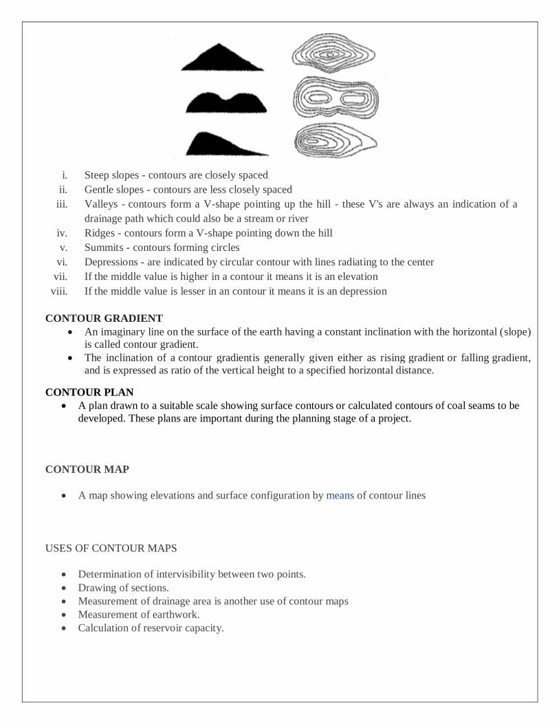
i. Steep slopes - contours are closely spaced
ii. Gentle slopes - contours are less closely spaced
iii. Valleys - contours form a V-shape pointing up the hill - these V's are always an indication of a
drainage path which could also be a stream or river
iv. Ridges - contours form a V-shape pointing down the hill
v. Summits - contours forming circles
vi. Depressions - are indicated by circular contour with lines radiating to the center
vii. If the middle value is higher in a contour it means it is an elevation
viii. If the middle value is lesser in an contour it means it is an depression
CONTOUR GRADIENT
An imaginary line on the surface of the earth having a constant inclination with the horizontal (slope)
is called contour gradient.
The inclination of a contour gradientis generally given either as rising gradient or falling gradient,
and is expressed as ratio of the vertical height to a specified horizontal distance.
CONTOUR PLAN
A plan drawn to a suitable scale showing surface contours or calculated contours of coal seams to be
developed. These plans are important during the planning stage of a project.
CONTOUR MAP
A map showing elevations and surface configuration by means of contour lines
USES OF CONTOUR MAPS
Determination of intervisibility between two points.
Drawing of sections.
Measurement of drainage area is another use of contour maps
Measurement of earthwork.
Calculation of reservoir capacity.

UNIT-3
CONTROL SURVEYING AND ADJUSTMENTS
CONTROL SURVEYING
Horizontal and vertical control are developed to create a framework around which other surveys can
be adjusted. These control surveys are used for accurate mapping projects in the construction of
underground utility systems, roadways, power lines, tunnels, and many other high precision projects.
HORIZONTAL CONTROLS & ITS METHODS
The horizontal control consists of reference marks of known plan position, from which salient points of
designed structures may be set out. For large structures primary and secondary control points are used.
The primary control points are triangulation stations. The secondary control points are reference to the
primary control stations.
Reference grids are used for accurate setting out of works of large magnitude. The following types of
reference grids are used:
SURVEY GRID
SITE GRID
STRUCTURAL GRID
SECONDARY GRID
SURVEY GRID
Survey grid is one which is drawn on a survey plan, from the original traverse. Original traverse
stations form the control points of the grid.
SITE GRID
The site grid used by the designer is the one with the help of which actual setting out is done. As
far as possible the site grid should be actually the survey grid. All the design points are related in
terms of site grid coordinates.
STRUCTURAL GRID
The structural grid is used when the structural components of the building are large in numbers
and are so positioned that these components cannot be set out from the site grid with sufficient
accuracy. The structural grid is set out from the site grid points.
SECONDARY GRID
The secondary grid is established inside the structure, to establish internal details of the building,
which are otherwise not visible directly from the structural grid.
VERTICAL CONTROL & ITS METHODS:

The vertical control consists of establishment of reference marks of known height relative to some
special datum. All levels at the site are normally reduced to the nearby bench mark, usually known as master bench mark.
The setting of points in the vertical direction is usually done with the help of following
rods:
1. Boning rods and travelers
2. Sight Rails
3. Slope rails or batter boards
4. Profile boards
1.BONING RODS AND TRAVELERS
A boning rod consist of an upright pole having a horizontal board at its top, forming a ‘T ‘shaped rod.
Boning rods are made in set of three, and many consist of three ‘T’ shaped rods, each of equal size
and shape, or two rods identical to each other and a third one consisting of longer rod with a detachable
or movable ‘T’ piece. The third one is called traveling rod or traveler.
2.SIGHT RAILS:
A sight rail consist of horizontal cross piece nailed to a single upright or pair of uprights driven into
the ground.
The upper edge of the cross piece is set to a convenient height above the required plane of the
structure, and should be above the ground to enable a man to conveniently align his eyes with the
upper edge.
A stepped sight rail or double sight rail is used in highly undulating or falling ground.
3.SLOPE RAILS OR BATTER BOARDS:
These are used for controlling the side slopes in embankment and in cuttings. These consist of two
vertical poles with a sloping board nailed near their top.
The slope rails define a plane parallel to the proposed slope of the embankment, but at suitable
vertical distance above it. Travelers are used to control the slope during filling operation.
4.PROFILE BOARDS:
These are similar to sight rails, but are used to define the corners, or sides of a building. A profile
board is erected near each corner peg.
Each unit of profile board consists of two verticals, one horizontal board and two cross boards.
Nails or saw cuts are placed at the top of the profile boards to define the width of foundation and
the line of the outside of the wall.
TRIANGULATION SURVEYING
Triangulation surveying is the tracing and measurement of a series or network of triangles to
determine distances and relative positions of points spread over an area, by measuring the length of
one side of each triangle and deducing its angles and length of other two sides by observation from
this baseline.
CLASSIFICATION OF TRIANGULATION SYSTEM:
The basis of the classification of triangulation figures is the accuracy with which the length and
azimuth of a line of the triangulation are determined. Triangulation systems of different accuracies depend on the extent and the purpose of the survey. The accepted grades of triangulation are:
1. First order or Primary Triangulation
2. Second order or Secondary Triangulation
3. Third order or Tertiary Triangulation
1. FIRST ORDER OR PRIMARY TRIANGULATION:
The first order triangulation is of the highest order and is employed either to determine the earth’s
figure or to furnish the most precise control points to which secondary triangulation may be
connected.
The primary triangulation system embraces the vast area (usually the whole of the country). Every
precaution is taken in making linear and angular measurements and in performing the reductions.
The following are the general specifications of the primary triangulation:
1. Average triangle closure : Less than 1 second
2. Maximum triangle closure : Not more than 3 seconds
3. Length of base line : 5 to 15 kilometers
4. Length of the sides of triangles : 30 to 150 kilometers
5. Actual error of base : 1 in 300,000
6. Probable error of base : 1 in 1,000,000
7. Discrepancy between two
measures of a section : 10 mm kilometers
8. Probable error or computed distance : 1 in 60,000 to 1 in 250,000
9. Probable error in astronomic azimuth : 0.5 seconds
2. SECONDARY ORDER OR SECONDARY TRIANGULATION
The secondary triangulation consists of a number of points fixed within the framework of primary
triangulation. The stations are fixed at close intervals so that the sizes of the triangles formed are smaller
than the primary triangulation. The instruments and methods used are not of the same utmost refinement. The general specifications of the secondary triangulation are:
1. Average triangle closure : 3 sec
2. Maximum triangle closure : 8 sec
3. Length of base line : 1.5 to 5 km
4. Length of sides of triangles : 8 to 65 km
5. Actual error of base : 1 in 150,000
6. Probable error of base : 1 in 500,000
7. Discrepancy between two
measures of a section : 20 mm kilometers
8. Probable error or computed distance : 1 in 20,000 to 1 in 50,000
9. Probable error in astronomic azimuth : 2.0 sec
3 THIRD ORDER OR TERTIARY TRIANGULATION:
The third-order triangulation consists of a number of points fixed within the framework of secondary triangulation, and forms the immediate control for detailed engineering and other surveys. The sizes of the triangles are small and instrument with moderate precision may be used. The specifications for a third-order triangulation are as follows:
1. Average triangle closure : 6 sec
2. Maximum triangle closure : 12 sec
3. Length of base line : 0.5 to 3 km
4. Length of sides of triangles : 1.5 to 10 km
5. Actual error of base : 1 in 75, 0000
6. Probable error of base : 1 in 250,000
7. Discrepancy between two
Measures of a section : 25 mm kilometers
8. Probable error or computed distance : 1 in 5,000 to 1 in 20,000
9. Probable error in astronomic Azimuth: 5 sec.
BASE LINE.
In surveying, a baseline is a line between two points on the earth's surface and the direction and
distance between them. In a triangulation network, at least one baseline needs to be measured to calculate the size of the triangles by trigonometry
FACTORS TO BE CONSIDERED WHILE SELECTING BASE LINE.
The measurement of base line forms the most important part of the triangulation operations. The base
line is laid down with great accuracy of measurement and alignment as it forms the basis for the
computations of triangulation system.
The length of the base line depends upon the grades of the triangulation. Apart from main base line,
several other check bases are also measured at some suitable intervals. In India, ten bases were used,
the lengths of the nine bases vary from 6.4 to 7.8 miles and that of the tenth base is 1.7 miles.
Selection of Site for Base Line. Since the accuracy in the measurement of the base line depends upon the site conditions, the following points should be taken into consideration while selecting the site:
1. The site should be fairly level. If, however, the ground is sloping, the slope should be uniform and gentle. Undulating ground should, if possible be avoided.
2. The site should be free from obstructions throughout the whole of the length. The line clearing should be cheap in both labour and compensation.
3. The extremities of the base should be intervisible at ground level.
4. The ground should be reasonably firm and smooth. Water gaps should be few, and if possible not
wider than the length of the long wire or tape.
5. The site should suit extension to primary triangulation. This is an important factor since the error in
extension is likely to exceed the error in measurement.
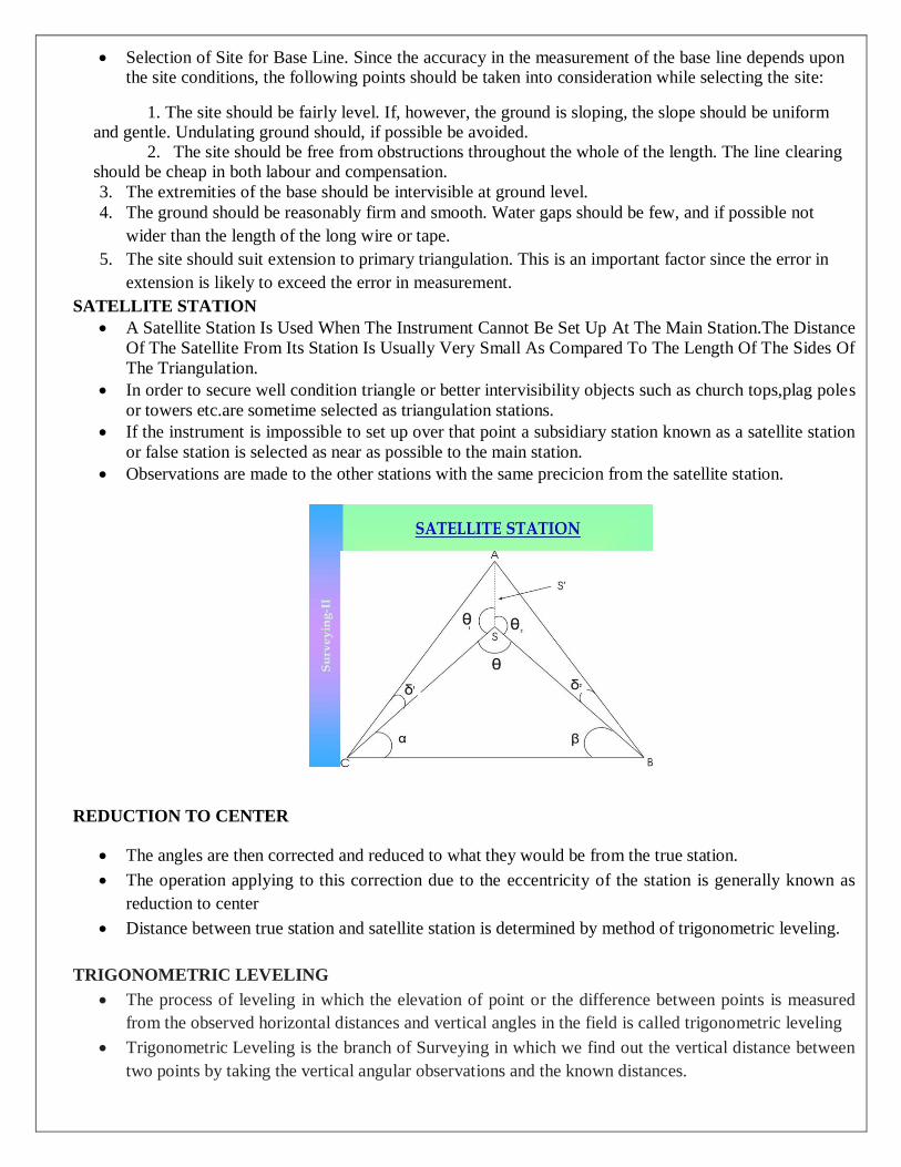
SATELLITE STATION
A Satellite Station Is Used When The Instrument Cannot Be Set Up At The Main Station.The Distance
Of The Satellite From Its Station Is Usually Very Small As Compared To The Length Of The Sides Of
The Triangulation.
In order to secure well condition triangle or better intervisibility objects such as church tops,plag poles
or towers etc.are sometime selected as triangulation stations.
If the instrument is impossible to set up over that point a subsidiary station known as a satellite station
or false station is selected as near as possible to the main station.
Observations are made to the other stations with the same precicion from the satellite station.
REDUCTION TO CENTER
The angles are then corrected and reduced to what they would be from the true station.
The operation applying to this correction due to the eccentricity of the station is generally known as
reduction to center
Distance between true station and satellite station is determined by method of trigonometric leveling.
TRIGONOMETRIC LEVELING
The process of leveling in which the elevation of point or the difference between points is measured
from the observed horizontal distances and vertical angles in the field is called trigonometric leveling
Trigonometric Leveling is the branch of Surveying in which we find out the vertical distance between
two points by taking the vertical angular observations and the known distances.

The known distances are either assumed to be horizontal or the geodetic lengths at the mean sea
level(MSL). The distances are measured directly(as in the plane surveying) or they are computed as in
the geodetic surveying.
The trigonometric Leveling can be done in two ways:
(1) Observations taken for the height and distances
(2) Geodetic Observations
(1) OBSERVATIONS TAKEN FOR THE HEIGHT AND DISTANCES :
In this way, we can measure the horizontal distance between the given points if it is accessible.
We take the observation of the vertical angles and then compute the distances using them. If the
distances are large enough then we have to provide the correction for the curvature and refraction and
that we provide to the linearly to the distances that we have computed.
(2) GEODETIC OBSERVATIONS:
In the second way, i.e geodetic observations, the distances between the two points are geodetic
distances and the principles of the plane surveying are not applicable here. The corrections for the
curvature and refraction are applied directly to the angles directly.
TRAVERSING
Traverse Is A Method In The Field Of Surveying To Establish Control Networks. It Is Also Used In
Geodesy.
Traverse networks Involve Placing Survey Stations Along A Line Or Path Of Travel, And Then
Using The Previously Surveyed Points As A Base For Observing The Next Point.
There Are Two Types Of Traverses:
Open Traverse
Closed Traverse.
OPEN TRAVERSE
An open traverse originates at a point of known position and terminates at a point of unknown
position.
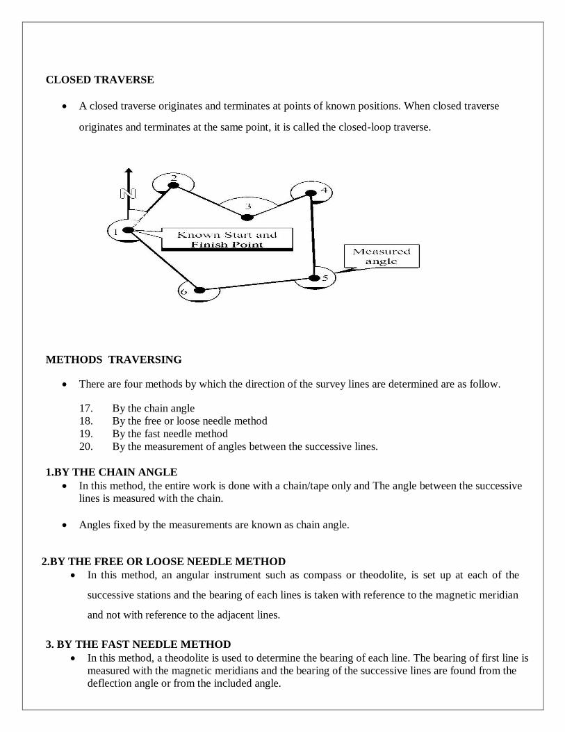
CLOSED TRAVERSE
A closed traverse originates and terminates at points of known positions. When closed traverse
originates and terminates at the same point, it is called the closed-loop traverse.
METHODS TRAVERSING
There are four methods by which the direction of the survey lines are determined are as follow.
17. By the chain angle
18. By the free or loose needle method
19. By the fast needle method
20. By the measurement of angles between the successive lines.
1.BY THE CHAIN ANGLE
In this method, the entire work is done with a chain/tape only and The angle between the successive
lines is measured with the chain.
Angles fixed by the measurements are known as chain angle.
2.BY THE FREE OR LOOSE NEEDLE METHOD
In this method, an angular instrument such as compass or theodolite, is set up at each of the
successive stations and the bearing of each lines is taken with reference to the magnetic meridian
and not with reference to the adjacent lines.
3. BY THE FAST NEEDLE METHOD
In this method, a theodolite is used to determine the bearing of each line. The bearing of first line is
measured with the magnetic meridians and the bearing of the successive lines are found from the
deflection angle or from the included angle.

4.BY THE MEASUREMENT OF ANGLES BETWEEN THE SUCCESSIVE LINES:
In this method, a theodolite is used for measurement of angles. The horizontal angles measured in a traverse
may be
• Included angles or
• Deflection angles (between the successive lines)
This is the most accurate method and is generally used for large surveys and accurate work.
GALE’S TABLE
Traverse computations are usually done in a tabular form is called Gale’s table
CHARACTERISTICS:
The sum of all the observed interior angles is found which should be equal to (2n-4) right
angle.
If exterior angles are measured then the sum should be equal to (2n+4) right angles.
Use Of Gale’s Table
The sum of latitudes (∑L) and departures (∑D) are found.
Necessary corrections are done in closed traverse such that ∑L = O and ∑D = O.
The independent coordinates of the lines are obtained from corrected consecutive
coordinates.
The coordinates are positive and the entire traverse lie in the first quadrant.
SOURCES OF ERROR IN MEASUREMENT
1. Instrumental errors
2. Personal errors
3. Natural errors
1.Instrumental errors
Error may arise due to imperfection or faulty adjustment of the instrument with which measurement is
being taken.
For example:
A tape may be too long or an angle measuring instrument maybe out of adjustment. Such errors are
known as Instrumental erros.
Personal Error
Error may also arise due to want of perfection of human sight in observing and of touch in
manipulating instruments.
For example:
An error maybe taking the level readings or reading an angle on a circle of theodolite. Such errors are
known as Personal errors.
Natural errors
Errors may also be due to variations in natural phenomena such as temperature, humidity, wind,
refraction and magnetic declination. If it is not properly observed while taking measurements, the
results will be incorrected.
TERMS USED FOR ERRORS IN SURVEYING
TRUE VALUE OF A QUANTITY
The value of a quantity which is absolutely free from any error is called the true value. It can never be
found out and the true value of a quantity is indeterminate.
MOST PROBABLE VALUE OF A QUANTITY
Most probable value of a given quantity from the given available set of observation is the one for
which the sum of the squares of the residual errors is a minimum.
The most probable value of a quantity is one which is most likely to be true value than any other
values. This is most likely to be free, but not likely to be absolutely free, from errors. In case of direct
observations of equal weight, the most probable value is the arithmetic mean. In case of direct
observations of unequal weights, the most probable value is the weights; the most probable value is the
weighted arithmetic mean.
WEIGHT OF AN OBSERVATION
The weight of an observation is a number giving an indication of its precision and trust worthiness,
when making a comparison between several quantities of different worth.
If a certain observation of weight 4 it means that it is 4 times as much reliable as an observation of
weight 1. When two quantities (or) observations are assumed to be equally reliable, the observed
values are said to be of equal weight (or) of unit weight
The weight of an observation is a factor depending on the importance attached to the observation. It
actually give an indication of the precision and trustworthiness of the observation when making a
comparison between several quantities of different worth.
PRINCIPLES OF LEAST SQUARES
The least squares principle states that the SRF should be constructed (with the constant and slope
values) so that the sum of the squared distance between the observed values of your dependent
variable and the values estimated from your SRF is minimized (the smallest possible value).
It is found from the probability equation that the most probable values of a series of
errors arising from observations of equal weight are those for which the sum of the squares is a
minimum.
The fundamental law of least squares is derived from this. According to the principle of least squares,
the most probable value of an observed quantity available from a given set of observations is the one
for which the sum of the squares of the residual errors is a minimum.
When a quantity is being deduced from a series of observations, the residual errors will be the
difference between the adopted value and the several observed values,
Let V1, V2, V3 etc. be the observed
NORMAL EQUATION
Is The One Which Is Formed By The Multiplying Each Equation By The Coefficient Of
The Unknown, Whose Normal Equation Is To Be Formed Out By Adding The Equation Thus Formed

ADJUSTMENTS OF SIMPLE TRIANGULATION NETWORKS.
Single angle
Station adjustment
Figure adjustment
STATION ADJUSTMENT
Sum Of The Angles About A Station Should Be 360o. If Not, Find The Difference And Adjust The
Difference Equally To All The Angles Algebraically To Make Their Sum Equal To 360o. Suppose;
For A Station B.
Angles Observed Value Correction Corrected Value
∟1 --- -12'' ---
∟2 --- -12'' ---
∟3 --- -12'' ---
∟4 --- -12'' ---
∑ = 360o 00' 48''
∑ = 360o 00' 00''
FIGURE ADJUSTMENT
The determination of most probable values of angles involved in any geometrical figure so as to fulfill
the geometrical conditions is called the figure adjustment. All cases of figure adjustment necessarily
involve one or more conditional equations. The geometrical figures used in a triangulation system are:
(a). Triangles.
(b). Quadrilaterals.
(c). Polygons with central stations.
UNIT 4
ADVANCED TOPICS IN SURVEYING
HYDROGRAPHIC SURVEYING
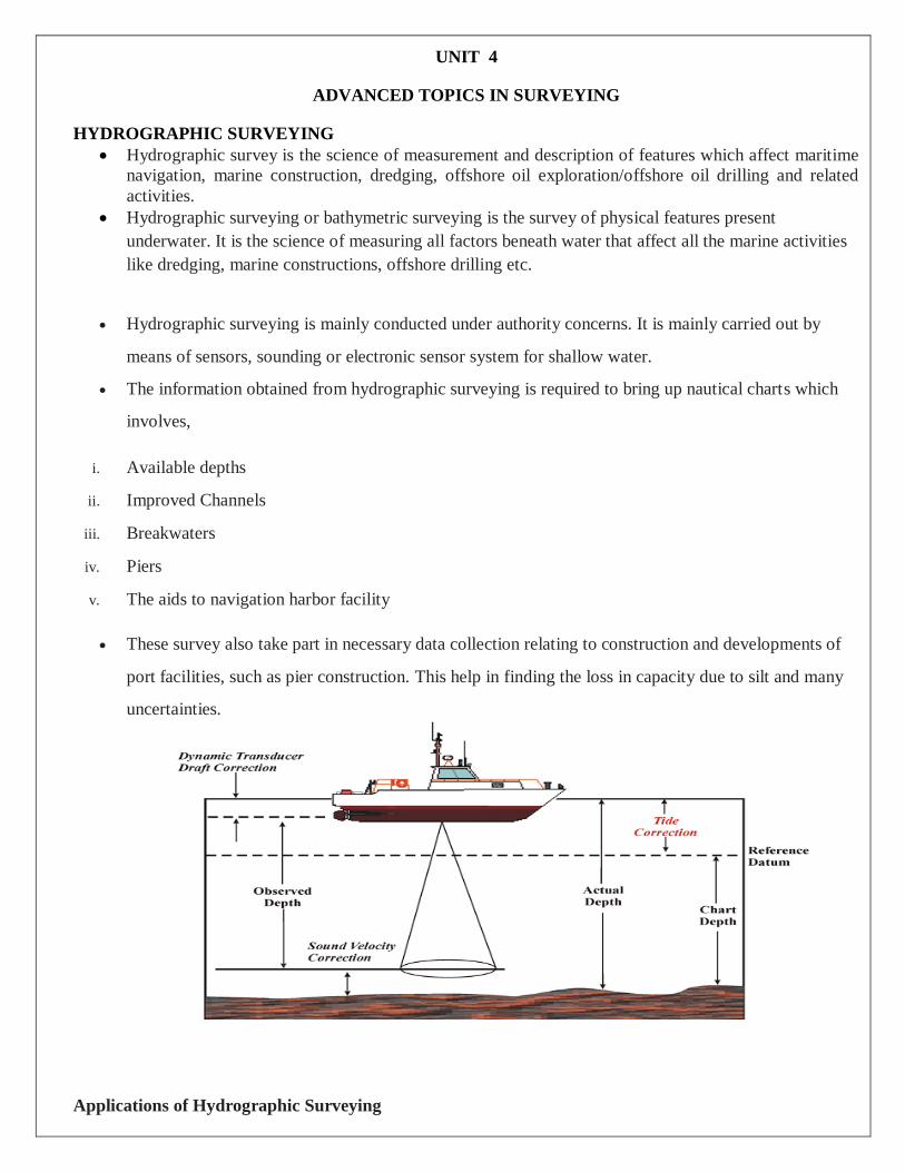
Hydrographic survey is the science of measurement and description of features which affect maritime
navigation, marine construction, dredging, offshore oil exploration/offshore oil drilling and related
activities.
Hydrographic surveying or bathymetric surveying is the survey of physical features present
underwater. It is the science of measuring all factors beneath water that affect all the marine activities
like dredging, marine constructions, offshore drilling etc.
Hydrographic surveying is mainly conducted under authority concerns. It is mainly carried out by
means of sensors, sounding or electronic sensor system for shallow water.
The information obtained from hydrographic surveying is required to bring up nautical charts which
involves,
i. Available depths
ii. Improved Channels
iii. Breakwaters
iv. Piers
v. The aids to navigation harbor facility
These survey also take part in necessary data collection relating to construction and developments of
port facilities, such as pier construction. This help in finding the loss in capacity due to silt and many
uncertainties.
Applications of Hydrographic Surveying

Following are the applications of hydrographic surveying:
o Dock and Harbor Engineering
o Irrigation
o River Works
o Land reclamation
o Water Power
o Flood Control
o Sewage Disposal
Uses of Hydrographic Surveying
Uses of hydrographic surveying are given below:
1. Depth of the bed can be determined
2. Shore lines can be determined
3. Navigation Chart Preparation
4. Locate sewer fall by measuring direct currents
5. Locating mean sea level
6. Scouring, silting and irregularities of the bed can be identified
7. Tide measurement
8. River and stream discharge measurement
9. Massive structures like bridges, dams harbors are planned
Preliminary Steps in Hydrographic Surveying
The method starts by locating special control points along the shore line. The sounding method is
employed to determine the depth at various points by means of stationary boats.
Sounding locations can be either made from boat to the control points or by fixing a point in the boat
and taking sounding from the control point. Before this procedure certain preliminary steps have to be
made:
1.Reconnaissance
2.Locate Horizontal Control
3.Locate vertical Control
1.Reconnaissance
As every project require a start-up plan to complete it effectively and economically, reconnaissance
has to be undergone. A complete reconnaissance of whole survey area to choose the best way of
performing the survey.
This would facilitate satisfactory completion of the survey in accordance with the requirements and
specifications governing such work. Aerial photographs would help this study.
2.Locating Horizontal Control
The horizontal control is necessary to locate all features of the land and marine in true relative
positions. Hence a series of lines whose lengths and azimuths are determined by means of either
triangulation or any other methods.
Tachometric and plane table survey can be conducted in order to undergo rough works. No rules are
kept for establishing horizontal control as topography, vegetation, type, size of topography affect the
rules.
But in general a rules can be kept for type of control say:
It is advisable to run traverses along each shore, connecting each other by frequent tie lines –If water
body > 1km wide
It is advisable to run transverse line only along one of the banks -If water body is narrow
Triangulation system -If shorelines filled by vegetation
Large network of triangulation system for large lakes and ocean shore lines
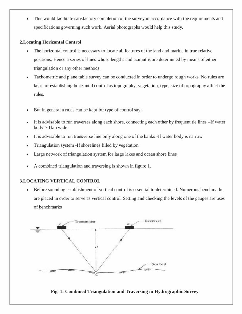
A combined triangulation and traversing is shown in figure 1.
3.LOCATING VERTICAL CONTROL
Before sounding establishment of vertical control is essential to determined. Numerous benchmarks
are placed in order to serve as vertical control. Setting and checking the levels of the gauges are uses
of benchmarks
Fig. 1: Combined Triangulation and Traversing in Hydrographic Survey
SOUNDING IN HYDROGRAPHIC SURVEY
The process of determining depth below water surface is called as sounding. The step before
undergoing sounding is determining the mean sea level.
If the reduced level of any point of a water body is determined by subtracting the sounding from mean
sea level, hence it is analogous to levelling.
Methods of Locating Soundings in Hydrographic Surveying
The soundings are located by the observations made from the boat or from the shore or from both.
There are four methods are there to locate the soundings by:
1. Conning the survey vessel
2. Observations with theodolite or sextant
3. Theodolite angles and EDM distances from the shore
4. Microwave systems
SOUNDING BY CONNING THE SURVEY VESSEL
In this method, conning means keeping the boat at known course. This method is suitable for rivers,
open sea up to 5 km off shore. The markers are fixed on the shore called as ranges along which vessel
or boat is run. This method is again sub divided into two types as follows.
Location by cross rope
Location by range and time interval
Location by Cross Rope
In this method, a wire or rope with markings or tags at known distances is stretched across the
channel. The starting point of rope at the shore is marked as reference point. Then using boat, the
sounding at different distances of wire are determined by weighted pole.
This method is more accurate. This is most suitable for rivers, narrow lakes and for harbors. This is
also suitable for knowing the amount of material removed by dredging.
Location by Range and Time Interval
In this method, the boat is positioned in range with two signals provided on the shore. Then, the boat is
rowed at constant speed and time required to reach the instant of sounding is measured which gives the
distance of total point along the range. This method is more suitable for less width channels or rivers.
It is not so much accurate.
SOUNDING BY OBSERVATIONS WITH THEODOLITE OR SEXTANT

Theodolite or sextant is used to measure angles in surveying. In this method, the sounding is located
by measuring angles. Here also, there are a lot of subdivided methods are there to locate sounding.
They are
By range and one angle from the shore
By range and one angle from the boat
By two angles form the shore
By two angles from the boat
By one angle from the shore and one angle from boat
By intersecting angles
By tachometry
By Range and One Angle from the Shore
In this method, boat is kept in range line with the help of two signals on the shore. The boat is
moved and the point where sounding is measuring is observed by the theodolite or sextant and
angle is noted. Using this angle, we can fix the point in the range.
Likewise, all other soundings are observed from different stations. The angle should be more
than 30 degrees otherwise fix should be poor.so, whenever the angle is less than 30o, new
instrument station is selected. This method is so accurate and easy for plotting the sounding
details.
By Range and One Angle from the Boat
This method is similar to the above method, but in this case, the angular measurements are
taken from the boat to different stations positioned on the shore. This is also having similar
accuracy to the above method.
But, there are some advantages in this method as compared with above method. Angle
measured from the shore from different stations is difficult when compared to angle observed
from the boat to all stations.
So, the surveyor in this case has better control over the operations. Check can be made by
measuring second angle towards some other signal on the shore for important fixes.

By Two Angles form the Shore
In this method, two instrument stations are fixed on the shore with proper distance. Two
instruments and two instrument men are required to do this job. From the two instrument
stations, angular observations are made and a point is located where sounding is measured.
If the angle made by instrument is less than 300 then new instrument station is selected. In this
case, primary setting out and erecting range signals are eliminated. This method is useful when
water currents are strong and difficult to row the boat along range line.
By Two Angles from the Boat
In this method, three constant points on the shore are selected. Using three-point problem, boat
is positioned in range line and angles are observed from the boat to two of the three known
positions.
The known positions may be light house, church spire, etc. like objects on the shore. If fixed
positions are not available, then go for shore signals or ranging rods.
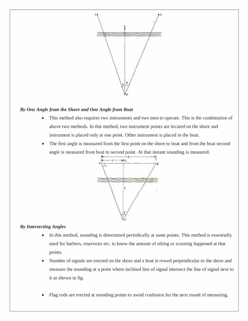
By One Angle from the Shore and One Angle from Boat
This method also requires two instruments and two men to operate. This is the combination of
above two methods. In this method, two instrument points are located on the shore and
instrument is placed only at one point. Other instrument is placed in the boat.
The first angle is measured from the first point on the shore to boat and from the boat second
angle is measured from boat to second point. At that instant sounding is measured.
By Intersecting Angles
In this method, sounding is determined periodically at same points. This method is essentially
used for harbors, reservoirs etc. to know the amount of silting or scouring happened at that
points.
Number of signals are erected on the shore and a boat is rowed perpendicular to the shore and
measure the sounding at a point where inclined line of signal intersect the line of signal next to
it as shown in fig.
Flag rods are erected at sounding points to avoid confusion for the next round of measuring.
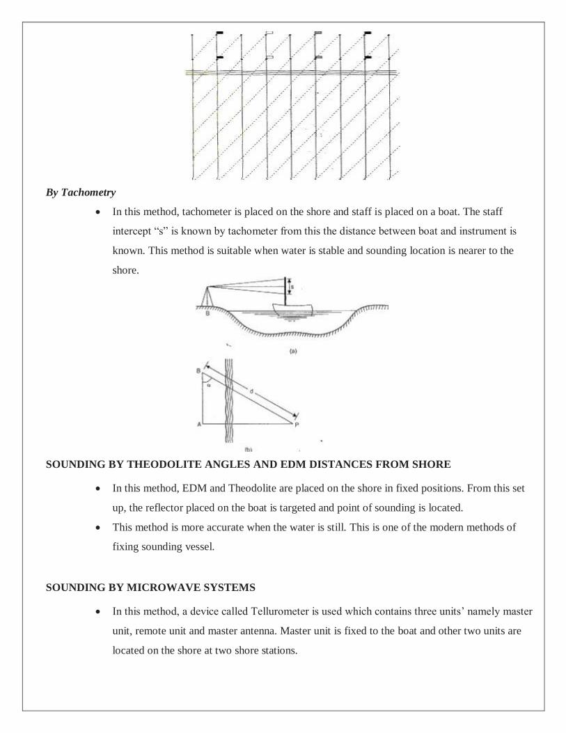
By Tachometry
In this method, tachometer is placed on the shore and staff is placed on a boat. The staff
intercept “s” is known by tachometer from this the distance between boat and instrument is
known. This method is suitable when water is stable and sounding location is nearer to the
shore.
SOUNDING BY THEODOLITE ANGLES AND EDM DISTANCES FROM SHORE
In this method, EDM and Theodolite are placed on the shore in fixed positions. From this set
up, the reflector placed on the boat is targeted and point of sounding is located.
This method is more accurate when the water is still. This is one of the modern methods of
fixing sounding vessel.
SOUNDING BY MICROWAVE SYSTEMS
In this method, a device called Tellurometer is used which contains three units’ namely master
unit, remote unit and master antenna. Master unit is fixed to the boat and other two units are
located on the shore at two shore stations.

The distances are measured from boat to the shore stations using micro waves produced by
tellurometer. Now from all these known distances the antenna produces the two sets of range
information. Tellurometer is useful for distances up to 100km from the shore.
The specific need for sounding are
1. Preparation of navigation charts that is an all-time information for future purpose also
2. Material that to be dredged has to be determined early to facilitate easy movement in project without any
confusion
3. Material dredging should also accompany where filling has to be done. Material dumping is also measured
4. Design of backwaters, sea wells require detailed information that is obtained from sounding
EQUIPMENT FOR SOUNDING
The essential equipment used for undergoing sounding are
1. Shore signals and buoys
2. Sounding Equipment
3. Instruments for measuring angles
1. SHORE SIGNAL AND BUOYS
These are required to mark the range lines. A line perpendicular to shore line obtained by line joining
2 or 3 signals in a straight line constitute the range line along which sounding has to be performed.
Angular observations can also be made from sounding boats by this method. To make it visible from
considerable distance in the sea it is made highly conspicuous.
A float made of light wood or air tight vessel which is weighted at bottom kept vertical by anchoring
with guywires are called buoys. In order to accommodate a flag a hole is drilled. Under water deep, the
range lines are marked by shore signals & the buoys.
2. SOUNDING EQUIPMENT
The individual units involved are explained one by one:
A. SOUNDING BOAT
A flat bottom of low draft is used to carry out sounding operation. Large size boats with motor are used for
sounding in sea. The soundings are taken through wells provided in the boat. A figure depicting sounding boat
is shown in fig.2.

Fig.2: Sounding Boat
B. SOUNDING POLE OR ROD
Rod made of seasoned timber 5 to 10cm diameter and 5 to 8m length. A lead shoe of sufficient weight is
connected at bottom to keep it vertical. Graduations are marked from bottom upwards. Hence readings on the
rod corresponding to water surface is water depth.
C. LEAD LINE
A graduated rope made of chain connected to the lead or sinker of 5 to 10kg, depending on current strength
and water depth. Due to deep and swift flowing water variation will be there from true depth hence a
correction is required.
Fig.3.Sounding Pole and Lead line
Other sounding equipment used are Weddell’s sounding machine. These are employed when large
sounding work has to be undergone. A standard machine to measure maximum of 30 to 40m is
designed that are bolted over the well of the sounding boat.
Another equipment used is fathometer which is an echo-sounding instrument used to determine ocean
depth directly. Recording time of travel by sound waves is the principle employed. Here the time of
travel from a point on the surface of the water to the bottom of the ocean and back is recorded.
Knowing the velocity of sound waves the depth can be calculated as shown in fig.4.
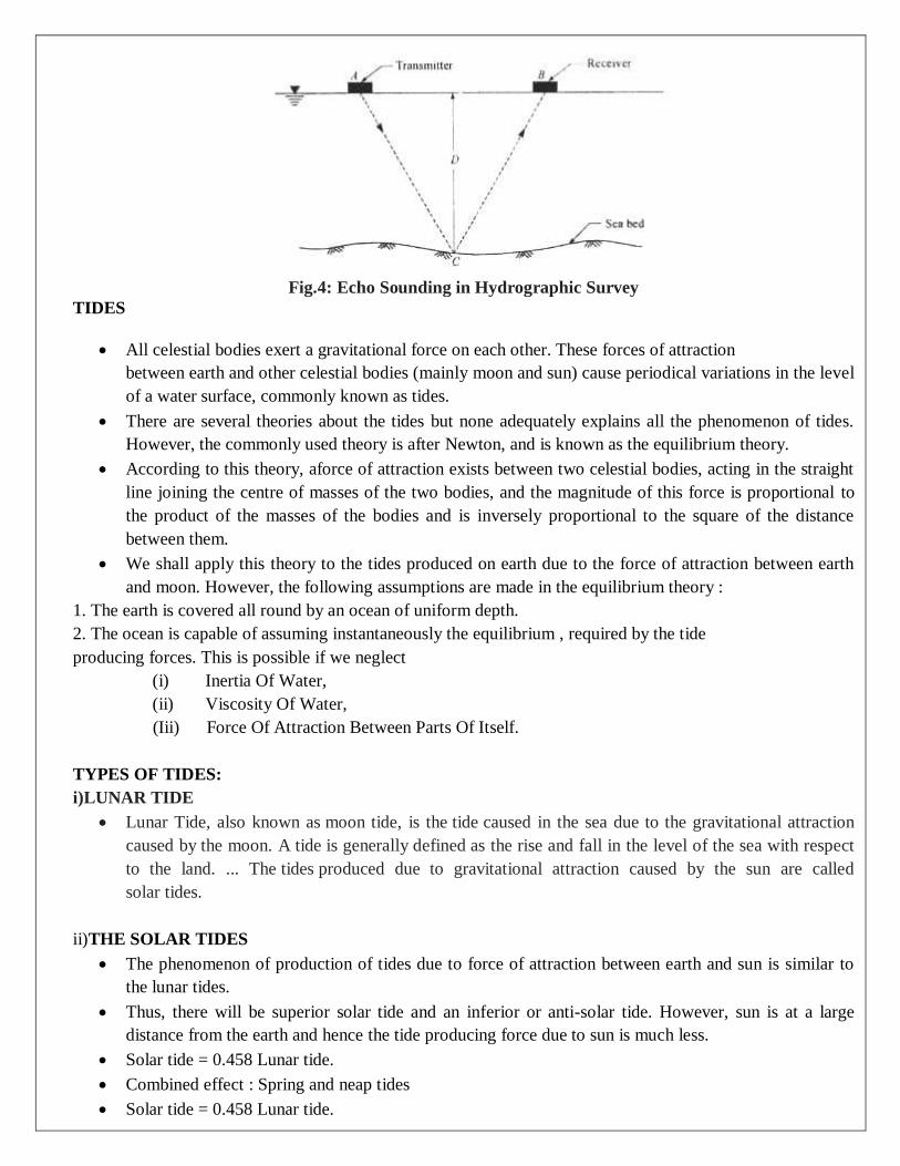
Fig.4: Echo Sounding in Hydrographic Survey
TIDES
All celestial bodies exert a gravitational force on each other. These forces of attraction
between earth and other celestial bodies (mainly moon and sun) cause periodical variations in the level
of a water surface, commonly known as tides.
There are several theories about the tides but none adequately explains all the phenomenon of tides.
However, the commonly used theory is after Newton, and is known as the equilibrium theory.
According to this theory, aforce of attraction exists between two celestial bodies, acting in the straight
line joining the centre of masses of the two bodies, and the magnitude of this force is proportional to
the product of the masses of the bodies and is inversely proportional to the square of the distance
between them.
We shall apply this theory to the tides produced on earth due to the force of attraction between earth
and moon. However, the following assumptions are made in the equilibrium theory :
1. The earth is covered all round by an ocean of uniform depth.
2. The ocean is capable of assuming instantaneously the equilibrium , required by the tide
producing forces. This is possible if we neglect
(i) Inertia Of Water,
(ii) Viscosity Of Water,
(Iii) Force Of Attraction Between Parts Of Itself.
TYPES OF TIDES:
i)LUNAR TIDE
Lunar Tide, also known as moon tide, is the tide caused in the sea due to the gravitational attraction
caused by the moon. A tide is generally defined as the rise and fall in the level of the sea with respect
to the land. ... The tides produced due to gravitational attraction caused by the sun are called
solar tides.
ii)THE SOLAR TIDES
The phenomenon of production of tides due to force of attraction between earth and sun is similar to
the lunar tides.
Thus, there will be superior solar tide and an inferior or anti-solar tide. However, sun is at a large
distance from the earth and hence the tide producing force due to sun is much less.
Solar tide = 0.458 Lunar tide.
Combined effect : Spring and neap tides
Solar tide = 0.458 Lunar tide.

Above equation shows that the solar tide force is less than half the lunar tide force.
However, their combined effect is important, specially at the new moon when both the sun
and moon have the same celestial longitude, they cross a meridian at the same instant.
MEAN SEA LEVEL
For all important surveys, the datum selected is the mean sea level at a certain place.
The mean sea level may be defined as the mean level of the sea, obtained by taking the mean of all the
height of the tide, as measured at hourly intervals over some stated period covering a whole number of
complete tides.
The mean sea level, defined above shows appreciable variations from day to day, from month to
month and from year to year.
Hence the period for which observations should be taken depends upon the purpose for which levels
are required.
The daily changes in the level of sea may be more. The monthly changes are more or less
periodic. The mean sea level in particular month may be low while it may be high in some other
moths.
Mean sea level may also show appreciable variations in its annual values. Due to
variations in the annual values and due to greater accuracy needed in modern geodetic
levelling, it is essential to base the mean sea level on observations extending over a period of about 19
years.
During this period, the moon’s nodes complete one entire revolution. The height of mean sea level so
determined is referred to the datum of tide gauge at which the observations are taken.
The point or place at which these observations are taken is known as a tidal station. If the observations
are taken on two stations, situated say at a distance of 200 to 500 kms on an open coast, one of the
station is called primary tidal station while the other is called secondary tidal station.
Both the stations may then be connected by a line of level.
ASTRONOMICAL SURVEYING
An astronomical survey is a general map or image of a region of the sky which lacks a specific
observational target. Alternatively, an astronomical survey may comprise a set of many images or
spectra of objects which share a common type or feature.
ASTRONOMICAL TERMS AND DEFINITIONS
To observe the positions / direction and movement of the celestial bodies, an imaginary sphere of
infinite radius is conceptualized having its centre at the centre of the earth. The stars are studded over
the inner surface of the sphere and the earth is represented as a point at the centre.
CELESTIAL SPHERE :
An imaginary sphere of infinite radius with the earth at its centre and other celestial bodies studded on
its inside surface is known as celestial sphere.
GREAT CIRCLE (G.C) :
The imaginary line of intersection of an infinite plane, passing through the centre of the earth and the
circumference of the celestial sphere is known as great circle.
ZENITH (Z) :
If a plumb line through an observer is extended upward, the imaginary point at which it appears to
intersect the celestial sphere is known as Zenith. The imaginary point at which it appears to intersect
downward in the celestial sphere is known as Nadir (N).
VERTICAL CIRCLE :
Great circle passing through zenith and nadir is known as vertical circle.
HORIZON:
Great circle perpendicular to the line joining the Zenith and Nadir is known as horizon.
POLES :
If the axis of rotation of the earth is imagined to be extended infinitely in both directions, the points at
which it meets the celestial sphere are known as poles.
The point of intersection in the northern hemisphere is known as north celestial pole and that in the
southern hemisphere as south celestial pole.
EQUATOR :
The line of intersection of an infinite plane passing through the centre of the earth and perpendicular to
the line joining celestial poles with the celestial sphere.
HOUR CIRCLE :
Great circle passing through celestial poles is known as hour circle, also known as declination circle.
MERIDIAN :
The hour circle passing through observer's zenith and nadir is known as (observer's) meridian. It
represents the North-South direction at observer station.
ALTITUDE (H) :
The altitude of a celestial body is the angular distance measured along a vertical circle passing through
the body. It is considered positive if the angle measured is above horizon and below horizon, it is

considered as negative.
AZIMUTH (A) :
The azimuth of a celestial body is the angular distance measured along the horizon from the observer's
meridian to the foot of the vertical circle passing through the celestial body .
THREE POINT PROBLEM
In this method, three well defined points, having locations already being plotted on the drawing are
involved. These are used to find and subsequently plot the location of the plane table station.
The method is based on the fact that, in a correctly oriented plane table, resectors through well defined
points get intersected at a point which represents the location of the plane table station on the drawing
There are several methods for solution of the three point problem:
(i) trial and Error method,
(ii) mechanical method,
iii)Graphical method,
(iv)Analytical method and
(v) geometrical construction method.
Of these, the trial and error method is easy, quick and accurate. It is commonly used in practice and
hence, has been discussed in detail.
In three point problem, if the orientation of the plane table is not proper, the intersection of the
resectors through the three points will not meet at a point but will form a triangle, known as triangle
of error (Figure).
The size of the triangle of error depends upon the amount of angular error in the orientation.
The trial and error method of three point problem, also knon as Lehman's method minimises the
triangle of error to a point iteratively. The iterative operation consist of drawing of resectors from
known points through their plotted position and the adjustment of orientation of the plane table.
The estimation of location of the plane table depends on its position relative to the well defined points
considered for this purpose. Depending on their relative positions, three cases may arise :

(i) The position of plane table is inside the great triangle;
(ii) The position of plane table is outside the great triangle;
(iii) The position of plane table lies on or near the circumference of the great circle.
In case of (iii), the solution of the three-point problem becomes indeterminate or unstable. But for
the cases (i) and (ii), Lehmann,s rules are used to estimate the location of plane table.
STEPS FOR THREE POINT PROBLEM
Let X, Y, and Z represent the ground location of the well defined objects whose plotted positions are
x, y, and z, respectively. Let P be the plane table station whose plotted position, say p, is to be
determined.
(i) Select a plane table position inside the great triangle XYZ and set up the table over P and orient it by
judgment so that apparent line xy is approximately parallel to the imaginary side XY.
(ii) Pivoting the alidade on x, y, and z bisect the signals placed at X, Y, and Z in turn and draw rays. If the
orientation of the table is correct, the three rays will meet at one point which is the desired location of p on
the sheet. If not, the rays will form a triangle of error
(iii)Choose a point p' inside the triangle of error such that its perpendicular distances from each ray is in
proportion to the respective distances of P from the three ground objects. For selection of location of p',
Lehmann's rules (1) and (3) need to be applied.
(iv) Align the alidade along p' x (assuming X to be the farthest station) rotate the table till flag at X is
bisected, and clamp the table.
(v) Pivoting the alidade on x, y, and z repeat the process as in step (ii) above. If the estimation of p as p' is
correct, the three rays will intersect at a point otherwise again a triangle of error will be formed but of smaller

size and within the previous triangle of error. .
(vi) Estimate again the location of p' in the new triangle of error applying the rules, (i) and (iii), and repeat
the steps (iv) and (v).
(vii) The method is repeated till all the three rays intersect at a point. The point of intersection is the required
location p of the plane-table station P.
STRENGTH OF FIX
The accuracy with which a plane table station can be located through three point problem is known as
its fix.
The degree of accuracy of solution of the three point problem is designated as its strength i.e., if the
accuracy is high, the fix is termed as strong and for low accuracy, fix is called as poor.
The accuracy of fix depends on the relative positions of the plotted points and that of location of the
plane table station. Thus, the choice of plotted objects and location of table should be made to get a
strong fix.
The strength of fix is good if
the location of station is chosen within the great triangle formed by joining the three well defined
objects X;
the middle object is nearer to the position of the plane table than other two objects;
of the two interior angles subtended by the three objects at the plane table stations, one is small and the
other is large. However, the objects subtending small angle should be widely separated to each other.
The strength of fix is poor if
The location of the plane table is on or near the circumference of the great circle.
Both the interior angles, subtended, by well defined objects, at the plane table stations, are small.
Figure 35.7 provides a pictorial representation of the quality of strength of figure with reference to the
location of the three chosen objects
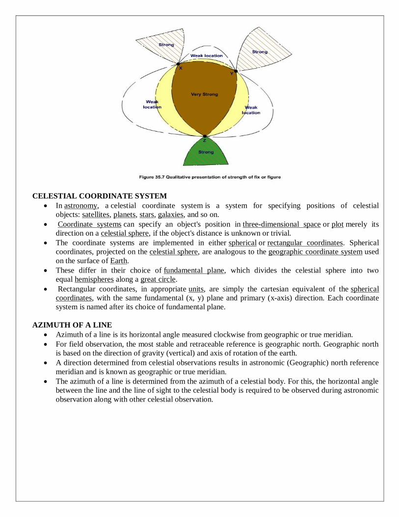
CELESTIAL COORDINATE SYSTEM
In astronomy, a celestial coordinate system is a system for specifying positions of celestial
objects: satellites, planets, stars, galaxies, and so on.
Coordinate systems can specify an object's position in three-dimensional space or plot merely its
direction on a celestial sphere, if the object's distance is unknown or trivial.
The coordinate systems are implemented in either spherical or rectangular coordinates. Spherical
coordinates, projected on the celestial sphere, are analogous to the geographic coordinate system used
on the surface of Earth.
These differ in their choice of fundamental plane, which divides the celestial sphere into two
equal hemispheres along a great circle.
Rectangular coordinates, in appropriate units, are simply the cartesian equivalent of the spherical
coordinates, with the same fundamental (x, y) plane and primary (x-axis) direction. Each coordinate
system is named after its choice of fundamental plane.
AZIMUTH OF A LINE
Azimuth of a line is its horizontal angle measured clockwise from geographic or true meridian.
For field observation, the most stable and retraceable reference is geographic north. Geographic north
is based on the direction of gravity (vertical) and axis of rotation of the earth.
A direction determined from celestial observations results in astronomic (Geographic) north reference
meridian and is known as geographic or true meridian.
The azimuth of a line is determined from the azimuth of a celestial body. For this, the horizontal angle
between the line and the line of sight to the celestial body is required to be observed during astronomic
observation along with other celestial observation.
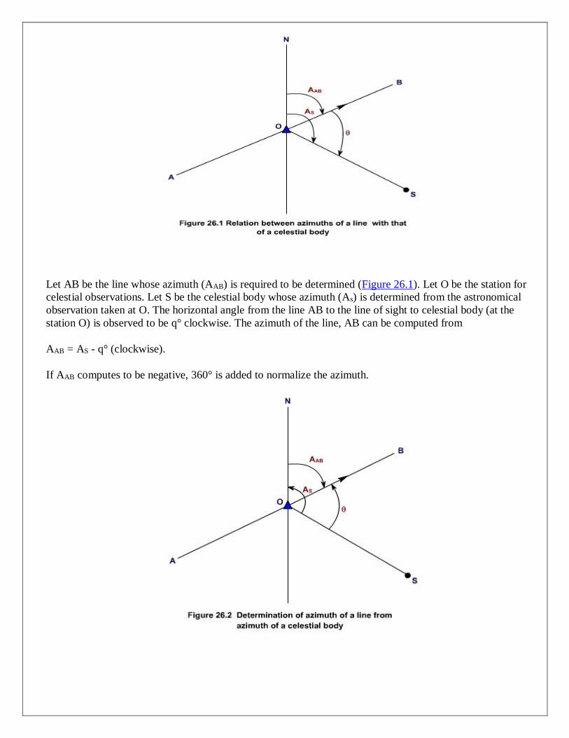
Let AB be the line whose azimuth (AAB) is required to be determined (Figure 26.1). Let O be the station for
celestial observations. Let S be the celestial body whose azimuth (As) is determined from the astronomical
observation taken at O. The horizontal angle from the line AB to the line of sight to celestial body (at the
station O) is observed to be q° clockwise. The azimuth of the line, AB can be computed from
AAB = AS - q° (clockwise).
If AAB computes to be negative, 360° is added to normalize the azimuth.

In order to compute the azimuth of a line with proper sign, it is better to draw the known parameters.
The diagram itself provides the azimuth of the line with proper sign. For example, in Figure 26.2, first
a line of sight to celestial body, OS is drawn.
Then, the azimuth of the celestial body, AS is considered in counter-clockwise from the line OS and
obtained the true north direction i.e, the line ON. Similarly, the horizontal angle q° is represented in
counter clockwise (since the angle from the line to the celestial body is measured clockwise) direction
from OS to obtain the relative position of the line. The angle NOB represents the azimuth of the line
AB.
DETERMINATION OF AZIMUTH OF A CELESTIAL BODY
In field astronomy, a celestial body provides the reference direction. So, from the geographic location
(latitude and longitude) of the station, ephemeris data of celestial body and either time or altitude of
the same celestial body, the azimuth of the celestial body is computed by solving astronomical
triangle.
If time is used, the procedure is known as the hour-angle method. Likewise, if altitude is measured, the
procedure is termed as the altitude method.
The basic difference between these two methods is that the altitude method requires observation of
approximate time and an accurate vertical angle of the celestial body, whereas the hour angle method
requires observation of accurate time.
Recent developments of time receivers and accurate timepieces, particularly digital watches with split -
time features, and time modules for calculators, the hour-angle method is more accurate, faster. It
requires shorter training for proficiency.
It has fewer restrictions on time of day and geographic location and thus is more versatile. The method
is applicable to the sun, Polaris, and other stars. Consequently, the hour-angle method is emphasized,
and its use by surveyors is encouraged.
HOUR ANGLE METHOD
In this method, precise time is being noted when the considered celestial body is being bisected. The
observed time is used to derive the hour angle and declination of the celestial body at the instant of
observation.
The geographic position (latitude and longitude) of the observation station is required to be known a
priori for the hour angle method. Usually, these values are readily obtained from available maps.
However, to achieve better accuracy, latitude and longitude must be more accurately determined
specially during observations for celestial bodies close to the equator--e.g., the sun-than for bodies
near the pole--e.g., Polaris.

The declination of the celestial bodies at the instant of observation is required to be known for
computation of azimuth of the celestial body. It is available in star almanac at the 0, 6, 12 and 18 hours
of UTI of each day ( Greenwich date). Thus, the declination at the instant of observation (of celestial
body) is determined by linear interpolation for corresponding the UT1 time of observation. However,
since the declination of the sun varies rapidly, its interpolation is done using the relation:
Declination, d = Decl 0h + (Decl 24h - Decl 0h) ( ) + (0.0000395) (Decl 0h) sin (7.5 UT1) -----------
--(Equation 26.2)
The hour-angle of the celestial body is being derived using the GHA (available in star almanac with
reference to Greenwich date) and the longitude of the observation station. For observations in the
Western Hemisphere, if UTI is greater than local time, the Greenwich date is the same as local date
and if UTI is less than local time, Greenwich date is the local date plus one day.
For the Eastern Hemisphere, if UTI is less than local time (24-hr basis), Greenwich date is the same as
local date and if UTI is greater than local time, Greenwich date is local date minus one day. The hour
angle of the celestial body at the observation station is the LHA.
Thus, it is the LHA at UTI time of observation which is necessary to compute the azimuth of a
celestial body. Hence, as can be seen from Figure 26.3, the equation for the LHA is
LHA = GHA - W l (west longitude) ----------------- (Equation 26.3)
Or LHA = GHA + E l (east longitude) -------------------(Equation 26.4)
LHA should be normalized to between 0° and 360° by adding or subtracting 360°, if necessary.
The Greenwich hour angle (GHA) of celestial bodies-the sun, Polaris, and selected stars-is tabulated in
star almanac from 0 hr to 24 hr at an interval of 6 hours of UTI time of each day (Greenwich date).
Thus, to find GHA at the time of observation linear interpolation is required to be performed.
The GHA can also be derived by making use of the equation of time E (apparent time minus mean
time) by using the relation:
GHA = 180° + 15 E ---------------------------Equation (26.5)
where E is in decimal hours. In those cases where E is listed as mean time minus apparent time, the
algebraic sign of E should be reversed.
Once the parameters (declination and Hour angle of the celestial body, latitude of the observation
station) required to compute the azimuth of the celestial body are available, the computation of
azimuth of the celestial body is carried out using the relations of astronomical triangle
UNIT 5
MODERN SURVEYING
TOTAL STATION
Total station is a surveying equipment combination of Electromagnetic Distance Measuring
Instrument and electronic theodolite.
It is also integrated with microprocessor, electronic data collector and storage system. The instrument
can be used to measure horizontal and vertical angles as well as sloping distance of object to the
instrument.
BASIC PRINCIPLE
Although taping and theodolites are used regularly on site – total stations are also used
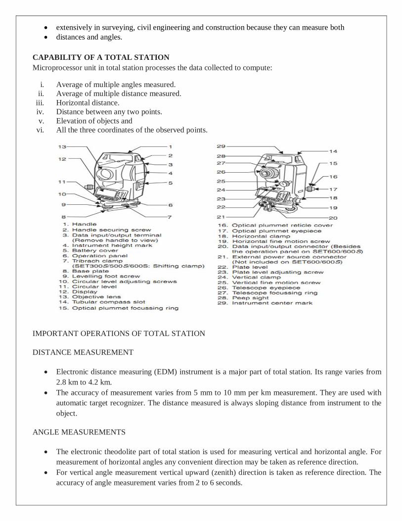
extensively in surveying, civil engineering and construction because they can measure both
distances and angles.
CAPABILITY OF A TOTAL STATION
Microprocessor unit in total station processes the data collected to compute:
i. Average of multiple angles measured.
ii. Average of multiple distance measured.
iii. Horizontal distance.
iv. Distance between any two points.
v. Elevation of objects and
vi. All the three coordinates of the observed points.
IMPORTANT OPERATIONS OF TOTAL STATION
DISTANCE MEASUREMENT
Electronic distance measuring (EDM) instrument is a major part of total station. Its range varies from
2.8 km to 4.2 km.
The accuracy of measurement varies from 5 mm to 10 mm per km measurement. They are used with
automatic target recognizer. The distance measured is always sloping distance from instrument to the
object.
ANGLE MEASUREMENTS
The electronic theodolite part of total station is used for measuring vertical and horizontal angle. For
measurement of horizontal angles any convenient direction may be taken as reference direction.
For vertical angle measurement vertical upward (zenith) direction is taken as reference direction. The
accuracy of angle measurement varies from 2 to 6 seconds.
DATA PROCESSING
This instrument is provided with an inbuilt microprocessor. The microprocessor averages multiple
observations.
With the help of slope distance and vertical and horizontal angles measured, when height of axis of
instrument and targets are supplied, the microprocessor computes the horizontal distance and X, Y, Z
coordinates.
The processor is capable of applying temperature and pressure corrections to the measurements, if
atmospheric temperature and pressures are supplied.
DISPLAY
Electronic display unit is capable of displaying various values when respective keys are pressed.
The system is capable of displaying horizontal distance, vertical distance, horizontal and vertical
angles, difference in elevations of two observed points and all the three coordinates of the observed
points.
ELECTRONIC BOOK
Each point data can be stored in an electronic note book (like compact disc).
The capacity of electronic note book varies from 2000 points to 4000 points data. Surveyor can unload
the data stored in note book to computer and reuse the note book.
USES OF TOTAL STATION
The total station instrument is mounted on a tripod and is levelled by operating levelling screws.
Within a small range instrument is capable of adjusting itself to the level position. Then vertical and
horizontal reference directions are indexed using onboard keys.
It is possible to set required units for distance, temperature and pressure (FPS or SI). Surveyor can
select measurement mode like fine, coarse, single or repeated.
When target is sighted, horizontal and vertical angles as well as sloping distances are measured and by
pressing appropriate keys they are recorded along with point number. Heights of instrument and
targets can be keyed in after measuring them with tapes. Then processor computes various information
about the point and displays on screen.
This information is also stored in the electronic notebook. At the end of the day or whenever electronic
note book is full, the information stored is downloaded to computers.
The point data downloaded to the computer can be used for further processing. There are software like
auto civil and auto plotter clubbed with AutoCad which can be used for plotting contours at any
specified interval and for plotting cross-section along any specified line.
ADVANTAGES OF USING TOTAL STATIONS
The following are some of the major advantages of using total station over the conventional surveying
instruments:
1. Field work is carried out very fast.
2. Accuracy of measurement is high.
3. Manual errors involved in reading and recording are eliminated.
4. Calculation of coordinates is very fast and accurate. Even corrections for temperature and pressure are
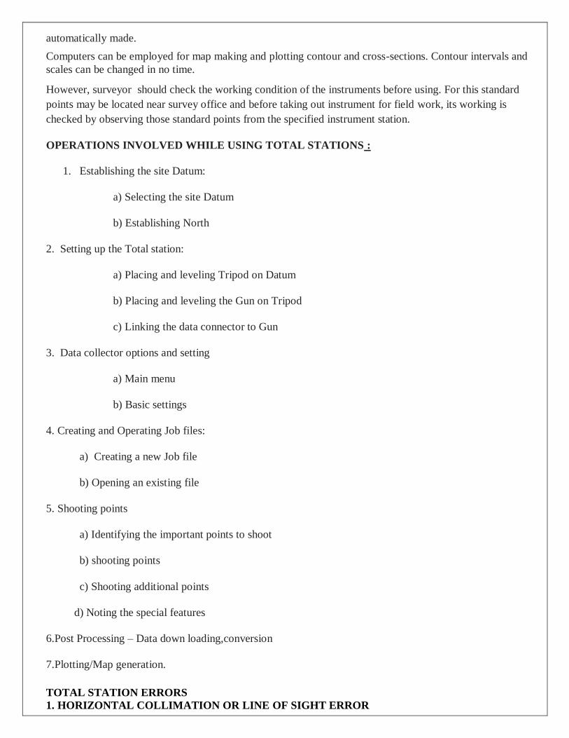
automatically made.
5. Computers can be employed for map making and plotting contour and cross-sections. Contour intervals and
scales can be changed in no time.
However, surveyor should check the working condition of the instruments before using. For this standard
points may be located near survey office and before taking out instrument for field work, its working is
checked by observing those standard points from the specified instrument station.
OPERATIONS INVOLVED WHILE USING TOTAL STATIONS :
1. Establishing the site Datum:
a) Selecting the site Datum
b) Establishing North
2. Setting up the Total station:
a) Placing and leveling Tripod on Datum
b) Placing and leveling the Gun on Tripod
c) Linking the data connector to Gun
3. Data collector options and setting
a) Main menu
b) Basic settings
4. Creating and Operating Job files:
a) Creating a new Job file
b) Opening an existing file
5. Shooting points
a) Identifying the important points to shoot
b) shooting points
c) Shooting additional points
d) Noting the special features
6.Post Processing – Data down loading,conversion
7.Plotting/Map generation.
TOTAL STATION ERRORS
1. HORIZONTAL COLLIMATION OR LINE OF SIGHT ERROR
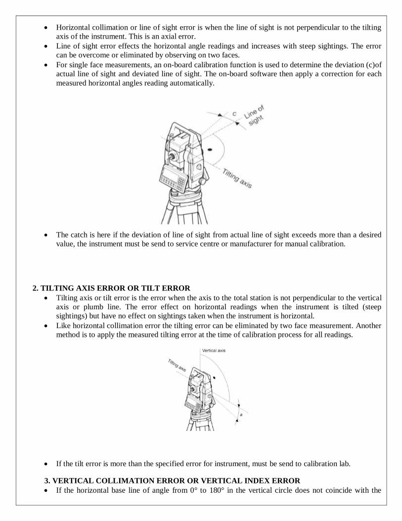
Horizontal collimation or line of sight error is when the line of sight is not perpendicular to the tilting
axis of the instrument. This is an axial error.
Line of sight error effects the horizontal angle readings and increases with steep sightings. The error
can be overcome or eliminated by observing on two faces.
For single face measurements, an on-board calibration function is used to determine the deviation (c)of
actual line of sight and deviated line of sight. The on-board software then apply a correction for each
measured horizontal angles reading automatically.
The catch is here if the deviation of line of sight from actual line of sight exceeds more than a desired
value, the instrument must be send to service centre or manufacturer for manual calibration.
2. TILTING AXIS ERROR OR TILT ERROR
Tilting axis or tilt error is the error when the axis to the total station is not perpendicular to the vertical
axis or plumb line. The error effect on horizontal readings when the instrument is tilted (steep
sightings) but have no effect on sightings taken when the instrument is horizontal.
Like horizontal collimation error the tilting error can be eliminated by two face measurement. Another
method is to apply the measured tilting error at the time of calibration process for all readings.
If the tilt error is more than the specified error for instrument, must be send to calibration lab.
3. VERTICAL COLLIMATION ERROR OR VERTICAL INDEX ERROR
If the horizontal base line of angle from 0° to 180° in the vertical circle does not coincide with the

vertical axis of instrument. This zero point error is present in all vertical circle readings and like the
horizontal collimation error, it is eliminated by taking FL and FR readings or by determining i.
4. COMPENSATOR INDEX ERROR
This error is caused by not leveling the total station correctly and carefully. This error can’t
be eliminated by taking two face (face left and face right) readings unlike the horizontal collimation
error.
If the instrument is fitted with a compensator it will measure residual tilts of the instrument and will
apply corrections to the horizontal and vertical angles for these.
However all compensators will have a longitudinal error l and traverse error t known as zero point
errors. These are averaged using face left and face right readings but for single face readings must be
determined by the calibration function of the total station.
SEGMENTS OF GPS
For better understanding of GPS, we normally consider three major segments viz.
space segment, Control segment and User segment. Space segment deals with GPS satellites systems,
Control segment describes ground based time and orbit control prediction and in User segment various
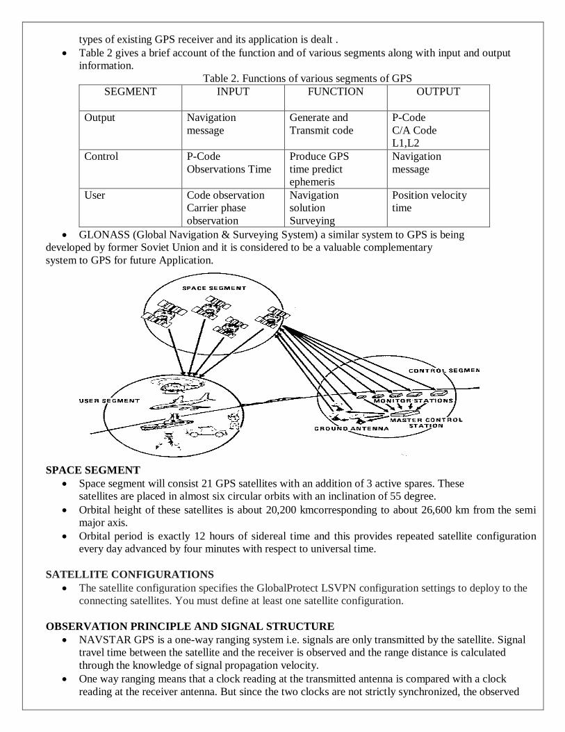
types of existing GPS receiver and its application is dealt .
Table 2 gives a brief account of the function and of various segments along with input and output
information.
Table 2. Functions of various segments of GPS
SEGMENT
INPUT FUNCTION OUTPUT
Output Navigation
message
Generate and
Transmit code
P-Code
C/A Code
L1,L2
Control
P-Code
Observations Time
Produce GPS
time predict
ephemeris
Navigation
message
User
Code observation
Carrier phase
observation
Navigation
solution
Surveying
Position velocity
time
GLONASS (Global Navigation & Surveying System) a similar system to GPS is being
developed by former Soviet Union and it is considered to be a valuable complementary
system to GPS for future Application.
SPACE SEGMENT
Space segment will consist 21 GPS satellites with an addition of 3 active spares. These
satellites are placed in almost six circular orbits with an inclination of 55 degree.
Orbital height of these satellites is about 20,200 kmcorresponding to about 26,600 km from the semi
major axis.
Orbital period is exactly 12 hours of sidereal time and this provides repeated satellite configuration
every day advanced by four minutes with respect to universal time.
SATELLITE CONFIGURATIONS
The satellite configuration specifies the GlobalProtect LSVPN configuration settings to deploy to the
connecting satellites. You must define at least one satellite configuration.
OBSERVATION PRINCIPLE AND SIGNAL STRUCTURE
NAVSTAR GPS is a one-way ranging system i.e. signals are only transmitted by the satellite. Signal
travel time between the satellite and the receiver is observed and the range distance is calculated
through the knowledge of signal propagation velocity.
One way ranging means that a clock reading at the transmitted antenna is compared with a clock
reading at the receiver antenna. But since the two clocks are not strictly synchronized, the observed

signal travel time is biased with systematic synchronization error.
Biased ranges are known as pseudoranges. Simultaneous observations of four pseudoranges are
necessary to determine X, Y, Z coordinates of user antenna and clock bias.
Real time positioning through GPS signals is possible by modulating carrier frequency with
Pseudorandom Noise (PRN) codes.
These are sequence of binary values (zeros and ones or +1 and -1) having random character but
identifiable distinctly. Thus pseudoranges are derived from travel time of an identified PRN signal
code.
Two different codes viz. P-code and C/A code are in use. P means precision or protected and C/A
means clear/acquisition or coarse acquisition.
Atomic Clock (G, Rb) fundamental
frequency
10.23. MHz
L1 Carrier Signal 154 X 10.23 MHz
L1 Frequency 1575.42 MHz
L1 Wave length 19.05 Cm
L2 Carrier Signal 120 X 10.23 MHz
L2 Frequency 1227.60 MHz
L2 Wave Length 24.45 Cm
P-Code Frequency (Chipping Rate) 10.23 MHz (Mbps)
P-CodeWavelength 29.31 M
P-Code Period 267 days : 7
C/A-Code Frequency (Chipping Rate) 1.023/MHz(Mbps)
C/A-Code Wavelength 293.1 M
C/A-Code Cycle Length 1Milisecond
Data Signal Frequency 50 bps
Data Signal Cycle Length 30 Seconds
STRUCTURE OF THE GPS NAVIGATION DATA
Structure of GPS navigation data (message) is shown in F The user has to decode
the data signal to get access to the navigation data.
For on line navigation purposes, the internal processor within the receiver does the decoding. Most of
the manufacturers of GPS receiver provide decoding software for post processing purposes. With a bit
rate of 50 bps and a cycle time of 30 seconds, the total information content of a navigationdata set is
1500 bits.
The complete data frame is subdivided into five subframes of sixsecond duration comprising 300 bits
of information. Each subframe contains the data words of 30 bits each. Six of these are control bits.
The first two words of each subframe are the Telemetry Work (TLM) and the C/A-P-Code Hand over
Work (HOW). The TLM work contains a synchronization pattern, which facilitates the access to the
navigation data. Since GPS is a military navigation system of US, a limited access to the total system
accuracy is made available to the civilian users.
CONTROL SEGMENT
Control segment is the vital link in GPS technology.Main functions of the control segment.
- Monitoring and controlling the satellite system continuously
- Determine GPS systemtime
- Predict the satellite ephemeris and the behavior of each satellite clock.
- Update periodically the navigation message for each particular satellite.
USER SEGMENT
Appropriate GPS receivers are required to receive signal from GPS satellites for the
purpose of navigation or positioning. Since, GPS is still in its development phase,many rapid
advancements have completely eliminated bulky first generation user equipments and now miniature
powerful models are frequently appearing in the market.
ORBIT DETERMINATION:
Orbit Determination is the process to estimate the position and velocity (state vector) of a satellite at a
specific epoch based on models of the forces acting on the satellite, integration of satellite orbital
motion equations and measurements to the satellites.
Orbit Determination (OD) is generally divided into two categories:
i. preliminary orbit determination
ii. precise orbit determination (POD).
PRELIMINARY ORBIT DETERMINATION
Preliminary Orbit Determination is a geometric method to estimate orbit elements from a minimal set
of observations before the orbit is known from other sources.
Traditionally, and still typically used, ground-based satellite observations of angles, distance or velocity
measurements, which depend on the satellite’s motion with respect to the centre of the Earth.
PRECISE ORBIT DETERMINATION
Precise Orbit Determination is a dynamic, or combined geometric and dynamic method, a process
completed with two distinct procedures: orbit integration and orbit improvement.
Orbit integration yields a nominal orbit trajectory, while orbit improvement estimates the epoch state
with all the measurements collected over the data arc in a batch estimation process .
ORBIT REPRESENTATION
Orbit Representation is a means of representing a satellite orbit as a continuous trajectory with discrete
observation data at the time of interest.
The simplest orbit representation is the “osculating Keplerian elements” method, which describes an
orbit as an ellipse.
The most typical example is the satellite almanacs published by NASA for almost all spacecrafts in
orbit. Figure 1.1 illustrates the concepts of the Keplerian elements with respect to the earth-centred
inertial coordinate system.
ANTI-SPOOFING
The function of anti-spoofing (AS) of the GPS system is designed for an anti potential spoofer (or
jammer). A spoofer generates a signal that mimics the GPS signal and attempts to cause the receiver to
track the wrong signal.
When the AS mode of operation is activated, the P code will be replaced with a secure Y code
available only to authorised users, and the unauthorised receiver becomes a single L1 frequency
receiver. AS had been tested frequently since 1 August 1992 and formally activated at 00:00 UT on 31
January 1994 and now is in continuous operation on all Block II and later satellites.
The broadcasted ionospheric model (in the navigation message) may be used to overcome the problem
of absence of the dual-frequencies, which are originally implemented for eliminating the ionospheric
effects. Of course, the method of using the ionospheric model cannot be as accurate as the method of
using dual-frequencies data, and consequently the precision is degraded. Carrier phase smoothed C/A
code may be used to replace the absence of the P code
SELECTIVE AVAILABILITY
Selective availability (SA) is a degradation of the GPS signal with the objective to deny full position
and velocity accuracy to unauthorised users by dithering the satellite clock and manipulating the
ephemerides.
In case SA is on, the fundament frequency of the satellite clock is dithered, so that the GPS
measurements are affected. The broadcast ephemerides are manipulated so that the computed orbit
will have slow variations. Several levels of SA effects are possible. The SA is enabled on Block II and
later satellites (Graas and Braasch 1996).
The authorised users may recover the un-degraded data and exploit the full system potential. For
doing so they must possess a key that allows them to decrypt correction data transmitted in the
navigation message (Georgiadou and Daucet 1990).
For high-precision users, IGS precise orbit and forecast orbit data may be used. Using known positions
(or monitor stations), the range corrections can be computed. Differential GPS may also eliminate at
least a part of the SA effects. SA has been switched off since May 2000.
HANDHELD GPS RECEIVERS
Handheld GPS receivers are used for absolute positioning or for relative positioning using DGPS-
services or WAAS/EGNOS signals. The positioning is realized using code pseudo-ranges.
Moreover it is well known that some of the handheld receivers use phase-smoothed code for
positioning. This means that the phase signal is available and may be used for Precise Differential GPS
(PDGPS) positioning.
GEODETIC RECEIVER
Geodetic GPS receivers have the advantage of providing additionally the P-code observations, with a
noise level smaller than the noise on the C/A code.
The accuracy requirements of geodetic receivers are usually about 1-5 cm (or even better).


