
Verification and Test Automation of UML Projects
Nikita Voinov, Vsevolod Kotlyarov(Saint-Petersburg State Polytechnic University)
The Third Spring Young Researchers Colloquium onSoftware Engineering
Moscow
May 28-29
2009
SYRCoSE 2009
2
Software Quality Assurance
• Unambiguity of requirementsSolution: usage of formal languages and notations (UML – Unified Modeling
Language)
• Software functionality’s correctness checkingSolution:– verification– testing
SYRCoSE 2009
3
Issues
• Model of the system on some formal language shall be created for verification
• Manual testing
Long and laborious processes
• Lack of technologies which allow to integrate testing and verification
SYRCoSE 2009
4
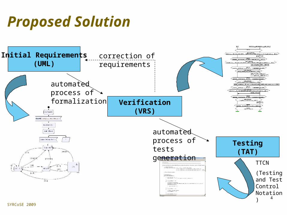
Proposed Solution
Initial Requirements(UML)
Verification(VRS)
Testing(TAT)
correction of requirements
TTCN
(Testing and Test Control Notation)
automated process of formalization
automated process of tests generation
SYRCoSE 2009
5
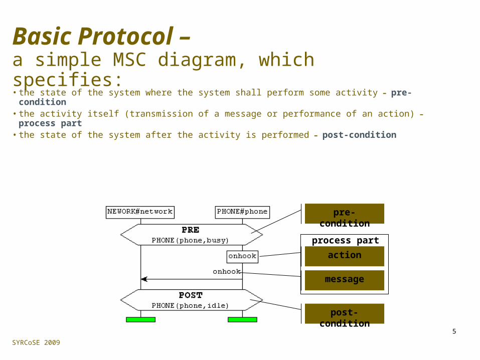
Basic Protocol –a simple MSC diagram, which specifies:
• the state of the system where the system shall perform some activity – pre-condition• the activity itself (transmission of a message or performance of an action) – process part• the state of the system after the activity is performed – post-condition
pre-condition
post-condition
action
message
process part

SYRCoSE 2009
6
VRS (Verification of Requirement Specifications)• combines model checking with deductive verification• checking the properties of requirements represented
with basic protocols• detection of non-deterministic behavior, unreachability
of specified states, deadlocks• criterion of requirement’s satisfiability in VRS is
existence of sequence of required events (actions, signals) contained in basic protocols in definite order; such sequence is called “trace”

SYRCoSE 2009
7
Conversion of a Fragment of UML SM Diagram into a Basic Protocol
Special VRS module “uml2bp”
is used for autoformalization
SYRCoSE 2009
8
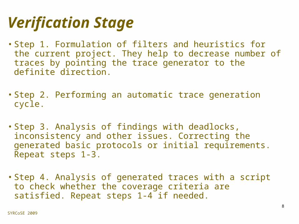
Verification Stage• Step 1. Formulation of filters and heuristics for the current
project. They help to decrease number of traces by pointing the trace generator to the definite direction.
• Step 2. Performing an automatic trace generation cycle.
• Step 3. Analysis of findings with deadlocks, inconsistency and other issues. Correcting the generated basic protocols or initial requirements. Repeat steps 1-3.
• Step 4. Analysis of generated traces with a script to check whether the coverage criteria are satisfied. Repeat steps 1-4 if needed.

SYRCoSE 2009
9
Sample State Machine Diagram
SYRCoSE 2009
10
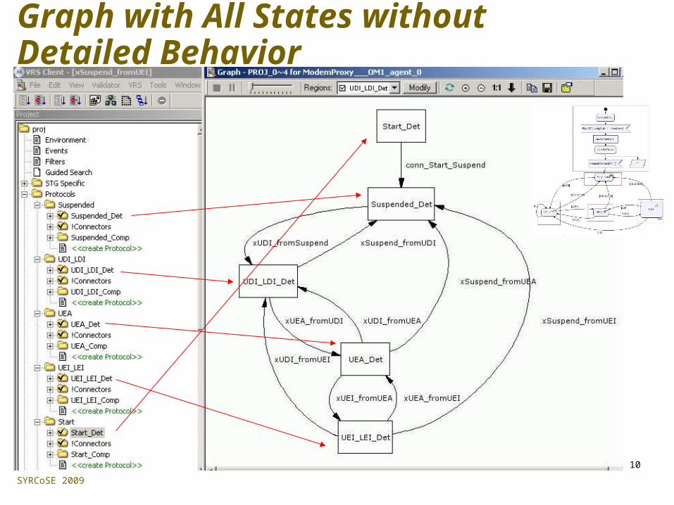
Graph with All States without Detailed Behavior

SYRCoSE 2009
11
Graph with All States with Detailed Behavior of ‘Suspended’ State
Suspended
Start
UDI_LDI
UEI_LEI
UEA

SYRCoSE 2009
12
Trace for the Graph with All States
SYRCoSE 2009
13
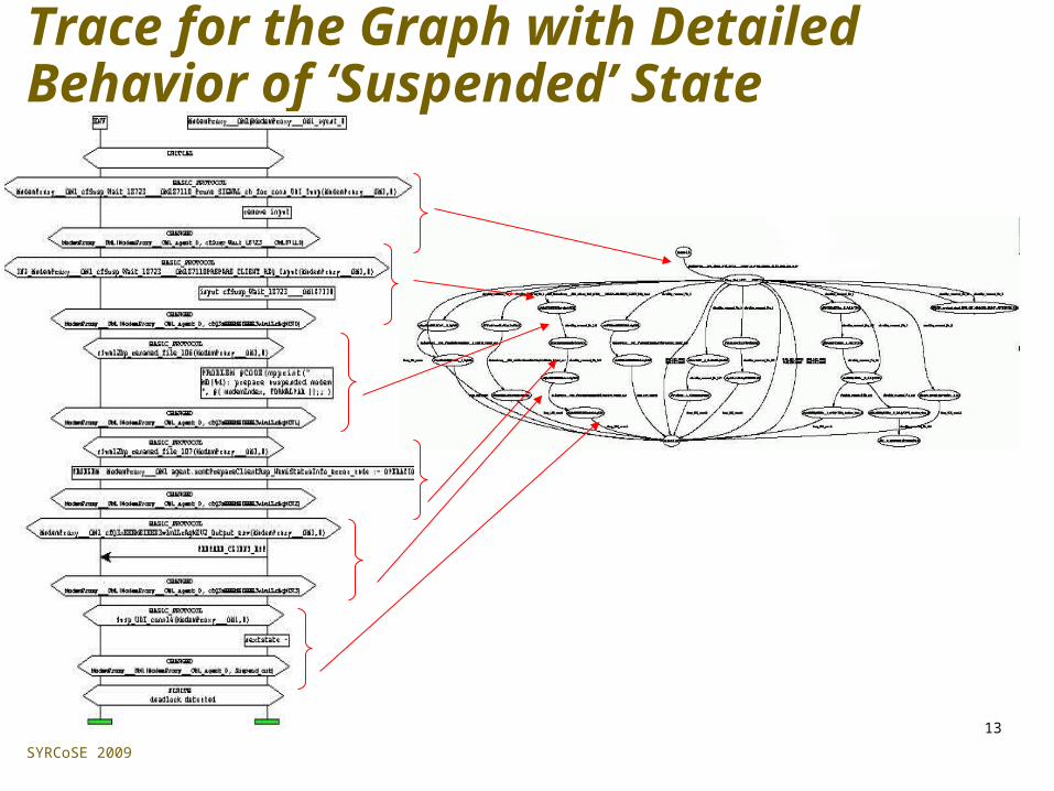
Trace for the Graph with Detailed Behavior of ‘Suspended’ State
SYRCoSE 2009
14
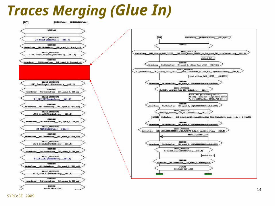
Traces Merging (Glue In)

SYRCoSE 2009
15
TAT (Test Automation Toolset)
• templates for generation of tests in C, Java, TTCN languages
• automated testing cycle based on user-defined scenarios developed in formal language MSC
• customizable for different platforms with different environments

SYRCoSE 2009
16
Overall Scheme of Automatic TTCN Tests Generation
UML diagram
SYRCoSE 2009
17
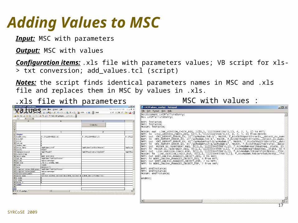
Adding Values to MSCInput: MSC with parameters
Output: MSC with values
Configuration items: .xls file with parameters values; VB script for xls-> txt conversion; add_values.tcl (script)
Notes: the script finds identical parameters names in MSC and .xls file and replaces them in MSC by values in .xls.
.xls file with parameters values : MSC with values :
SYRCoSE 2009
18
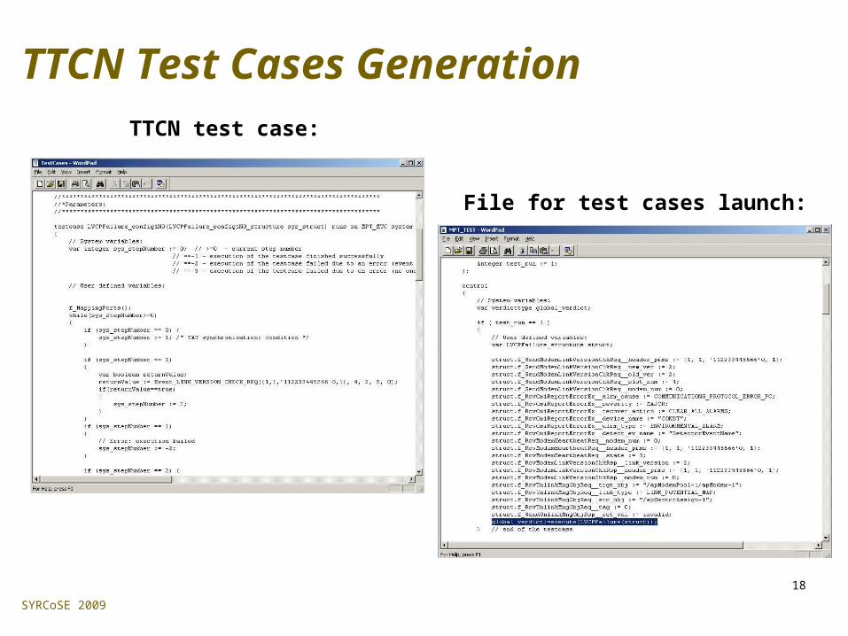
TTCN Test Cases GenerationTTCN test case:
File for test cases launch:
SYRCoSE 2009
19
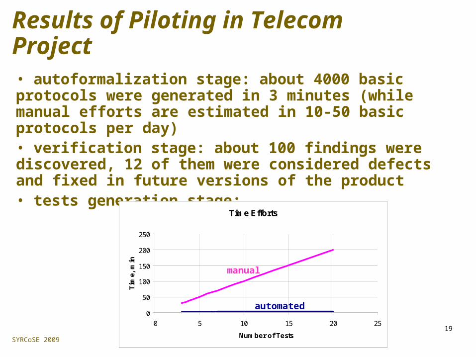
Results of Piloting in Telecom Project• autoformalization stage: about 4000 basic protocols were generated in 3 minutes (while manual efforts are estimated in 10-50 basic protocols per day)• verification stage: about 100 findings were discovered, 12 of them were considered defects and fixed in future versions of the product• tests generation stage:
Time Efforts
0
50
100
150
200
250
0 5 10 15 20 25
Number of Tests
Tim
e, m
in
manual
automated

SYRCoSE 2009
20
Novelty of Work
• automated conversion of UML specifications into formal model in the language of basic protocols
• methodic of large-scale models analysis using VRS technology
• new TAT template for generation of tests in TTCN language
SYRCoSE 2009
21
THANK YOU


