V E R S A L O C® G U I D EA N A D B R I M A S O N R Y L I C E N C E D P R O D U C T
V E R Y Q U I C K , V E R Y E A S Y
2 adbri masonry
Preface 02
Introduction 02
1.0 Versaloc® Retaining Walls
1.1 Designs for reinforced retaining walls type 1 and type 2 03
1.2 Design Details 04
1.3 Material specifications 04
1.4 Soil classification of backfill material, retained soil, and foundation soil 04
1.5 Backfill Material and Retained Soil 05
1.6 Foundation Soil 05
1.7 Drainage system 05
1.8 Water penetration 05
1.9 Tanking 05
1.10 Backfill Compaction and Drainage System 05
1.11 Seismic Zones 05
1.12 Good Ground 06
1.13 How to build the Versaloc® wall 06 1.13.1 Preliminary 06
1.13.2 Base & starter bars 06
1.13.3 Block laying 06
1.13.4 Bracing 06
1.13.5 Grouting 06
1.14 Exploded view of construction 09
1.15 Versaloc® type 1 retaining wall design details for level backfill slopes using 200 series 10
1.15.1 General layout for walls up to 2400mm high 10
1.15.2 Design details for walls up to 2400mm high with level backfill slope 11
1.16 Versaloc® type 1 retaining wall design details for 1:4 backfill slopes using 200 series blocks 12
1.16.1 General layout for walls up to 1800mm high with 1:4 backfill slope 12
1.16.2 Design details for walls up to 1800mm high with 1:4 backfill slope 13
1.17 Versaloc® type 2 retaining walls design details for level backfill slopes using 200 series blocks 14
1.17.1 General layout for walls up to 2400mm high with level backfill slope 14
1.17.2 Design details for walls up to 2400mm high with level backfill slope 15
1.18 Versaloc® type 2 retaining walls design details for 1:4 backfill slopes using 200 series blocks 16
1.18.1 General layout for walls up to 1800mm high with 1:4 backfill slope 16
1.18.2 Design details for walls up to 1800mm high with 1:4 backfill slope 17
2.0 Compressive load capacity Versaloc® walls 18
3.0 Versaloc® block series data sheet 19
Designs shown in the brochure are based on limit state design in accordance with the provisions of NZS3101-2006.
The retaining wall design details provided in this brochure have been prepared specifically for mortarless Versaloc® blocks and are applicable only to retaining walls using Bowers Brothers Versaloc® products for residential or light commercial applications up to 2.4m high with Type 1 and Type 2 bases and 200 series blocks.
Also included is a table showing compressive load capacity of Versaloc® walls up to 6.0m high with two load cases using 200 series blocks.
CONTENTS PREFACE
INTRODUCTIONReinforced Bowers Brothers Versaloc® block retaining walls consist of a reinforced concrete base which anchors the wall against overturning and sliding, and a stem of mortarless Versaloc® blocks. Stems are reinforced with steel bars placed vertically and horizontally, and all cores in the blocks are filled with semi-fluid concrete known as ‘grout’. Vertical reinforcing bars in the cores of reinforced walls are lapped with shorter ‘starter bars’ embedded firmly in the reinforced concrete base. The length of the lap is critically important and must be shown on the drawings.
The designs in this brochure have been checked and approved by:
Frontier Engineers P O Box 79183
Avonhead Christchurch 8446 Ph: +64 3359 9192
For any designs outside the scope of those included in this brochure, please contact Frontier Engineers directly.

adbri masonry 3
1.1 Designs for reinforced retaining walls type 1 and type 2
Designs consist of: 200 series block retaining walls up to 2.4m high for level backslope and 1.8m high for 1:4 backslope
1.0 VERSALOC® RETAINING WALLS
45ºapprox
Boundary
Drain
Versaloc™reinforcedblock stem
Base
Natural foundation soil
DrainageLayer
Backfillmaterial
Retained soil
Boundary
Drain
Base
DrainageLayer
Backfillmaterial
Retained soil
45ºapprox
Versaloc™reinforcedblock stem
Naturalfoundationsoil
Wall Type 1
Wall Type 2
4 adbri masonry
1.2 Design details
1.2.1 Design details for walls up to 2400mm high with level backfill slope with Type 1 base
1.2.2 Design details for walls up to 1800mm high with 1:4 backfill slope with Type 1 base
1.2.3 Design details for walls up to 2400mm high with level backfill slope with Type 2 base
1.2.4 Design details for walls up to 1800mm high with 1:4 backfill slope with Type 2 base
1.3 Material specifications
Versaloc® Block 190mm f’m = 25.0 MPa
Concrete base f’c = 25 MPa
Reinforcement Grade 500 E
Grout Refer section
1.4 Soil classification of backfill material, retained soil and foundation soil
1.4.1 Wall Type 1 and 2 For simplicity wall type 1 and 2 design details in this brochure for backfill material, retained soil and foundation soil are based on a common soil with the following typical properties; coarse grained with low permeability due to admixture of particles of silt size, residual soil with stones, fine silty sand and granular materials with conspicuous clay content with an internal friction angle of 30º. Note: often retained soil is used as backfill material if suitable.
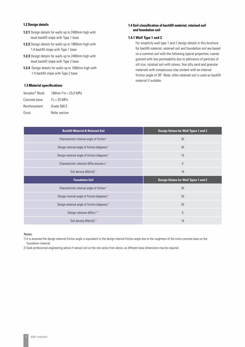
Backfill Material & Retained Soil Design Values for Wall Types 1 and 2
Characteristic internal angle of friction * 30
Design internal angle of friction (degrees) * 30
Design external angle of friction (degrees) * 15
Characteristic cohesion (kPa) assume c * 0
Soil density (kN/m3) * 18
Foundation Soil Design Values for Wall Types 1 and 2
Characteristic internal angle of friction * 30
Design internal angle of friction (degrees) * 30
Design external angle of friction (degrees) * 20
Design cohesion (kPa) c* * 0
Soil density (kN/m3) * 18
Notes:1) It is assumed the design external friction angle is equivalent to the design internal friction angle due to the roughness of the insitu concrete base on the
foundation material.2) Seek professional engineering advice if natural soil on the site varies from above, as different base dimensions may be required.

adbri masonry 5
1.5 Backfill Material and Retained Soil
Retaining wall designs in this brochure have been calculated for backfill material and retained soil of soil classification as shown in section 1.4.
Note: The following poor quality soils are not allowed for in the designs:
• very soft clay of high plasticity• very silty clays• very loose variable clayey fill• very loose sandy silts• with characteristic internal angle of friction below 28 degrees.
If these soils are considered for use or aggressive groundwater exists an experienced professional engineer should be consulted and separate designs be obtained.
1.6 Foundation Soil
1.6.1 Wall Type 1 and 2The design details have been based on a foundation soil as described in section 1.4 and which must be excavated to sufficient depth to expose undisturbed material which is firm and dry.
Note 1: Should a designer wish to analyse a retaining wall with better quality retained soil than the soil nominated in section 1.4, base dimensions different from the tabulated values could be appropriate and it is recommended professional engineering advice is sought.
Note 2: If any of the following foundation conditions exist: softness, poor drainage, filled ground, organic matter, variable conditions, heavily cracked rock, aggressive soils, then experienced professional engineering advice should be obtained.
1.7 Drainage System
It is essential that steps be taken to prevent the soil behind the wall from becoming saturated. These steps should include:
• Sealing the soil surface - this can be done by covering it with a compacted layer of material with low permeability (eg clay). The surface should be sloped towards an open drain.
• A drainage system within the soil - this should preferably be achieved by placing gravel to a width of approximately 300mm immediately behind the wall with a continuous 100mm diameter slotted pvc agricultural pipe with a geo fabric sock located at the base of the wall. The outlets from the pipe must be beyond the ends of the wall unless the pipe is connected to a proper storm water drainage system.
For higher walls, or in cases where excessive ground water exists, it may be necessary to provide another agricultural pipe drain at mid height of the wall. If it is not possible to discharge the drains beyond the end of the wall, weep-holes may be provided (see items for block laying following). In this case, a collecting system (eg spoon drains) must discharge the water into a drainage system to prevent saturation of the ground in front of the wall.
1.8 Water penetration
If considered necessary to reduce the passage of water through the wall, for aesthetic or other reasons such as aggressive ground water, the earth face of the wall should be treated using appropriate sealing techniques (see notes on tanking).
1.9 Tanking
Where the retaining wall is required to be waterproof, various proprietary tanking methods are available. One such method is a three coat liquid rubber compound incorporating a special reinforcing fabric for high stressed areas.
Another method is a heavy duty, pliable, waterproof sheet membrane fixed to the wall back surface. Surface coatings or sheet membranes must always be used in accordance with the manufacturer’s specifications.
1.10 Backfill compaction and drainage system
Backfill material should not placed behind the wall until at least ten days after grouting.
• Backfill material should be placed and compacted in layers not more than 200 mm deep. The degree and method of compaction depends on the proposed use of the retaining wall. If unsure, obtain professional engineering device.
• The drainage system should be installed progressively as the backfill soil rises.
• The drainage system behind the wall should be connected to the main drainage system for the site.
• It is advisable to seal off the top surface of the backfill material with a semi impermeable layer of soil or earth (eg clay). Compact and grade the material to a gutter to provide surface drainage.
1.11 Seismic Zones
The retaining wall designs are suitable for seismic zones 1 and 2 as defined in NZS4429. This can be translated to a hazard factor of Z=0.3 as defined in NZS1170.5.
The retaining walls detailed are only suitable for importance level 1 applications (as defined in NZS1170 part O). Furthermore, the designs are only suitable for applications where the retaining wall is not integral to dwelling / structure.
The tables have been designed assuming negligible vertical seismic acceleration. In applications where vertical seismic accelerations are deemed important, engineering input is required.

6 adbri masonry
1.12 Good Ground
The retaining wall tables are only applicable for bearing on “Good Ground” as defined in NZS3604. This excludes (but is not limited to) the conditions listed below:
• Liquefiable soils.
• Expansive soils.
• Soils with an ultimate bearing capacity below 300kPa.
• Soils with an undrained shear strength below 50kPa.
• Any ground which may experience 25mm of settlement.
A geotechnical engineer should confirm the assumption of “Good Ground” on a site specific basis.
1.13 How to build the Versaloc® wall
1.13.1 Preliminary
• Excavate to a satisfactory foundation.
• Arrange for supply of materials to the specifications given previously.
1.13.2 Base and starter bars
• Form the base to the required dimensions and levels as shown in details.
• Place the base reinforcement as shown in the diagrams. Fix the starter bars for the vertical reinforcement (Y-bars) at the correct cover specified in the drawings from the back face of the wall (i.e 50mm) and in the correct positions relative to the block cores to be reinforced. Place horizontal bars in the center on the cross webs.
• Place the base concrete, preferably using ready-mixed concrete, and compact thoroughly by rodding, spading or vibrating. Wood float finish any surface to be exposed permanently. Take care not to dislodge reinforcement.
Note: First reinforcement bar is placed at 60mm from the end (to avoid cross web).
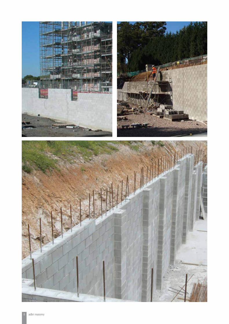
1.13.3 Block laying
• Block laying procedure follows that of the normal practice but without the need to mortar the blocks together.
Note: The first layer of blocks should be mortared to the concrete base in the normal way to provide line and level for the remaining block courses.
• The blocks are laid with the shallow recessed cross webs at the top (refer diagram 1.14.1). During construction, it is important to keep debris off the bed joint plane; otherwise the wall may begin to develop vertical curvature. In addition, as a unit is positioned, some small particles of concrete may be rubbed off the units and fall on the bed joint surface. Usually the force of placing the block
will crush these particles. Otherwise, rubbing the block back and forth along the joint will wear down the material. If a joint is visibly open, the unit should be removed and the debris removed.
Note: Small plastic wedges can be used under blocks to achieve vertical alignment.
• Provided the construction is started on a level surface, use of a line and carpenters’ level should be all that are required to keep the wall aligned vertically and horizontally. In instances where the wall is accidentally laid out of line, this can usually be corrected by using a piece of wood to protect the wall and a heavy hammer to knock the wall back into line.
• At the end of walls, Half Sash blocks may be glued to the block directly below using an appropriate adhesive to increase stability. (eg 2 part epoxy or equivalent)
• Blocks should be laid in running bond with head joints aligned vertically every second course. Exact overlapping by half of a block will ensure that the webs and cells are aligned vertically.
• Weepholes can be provided by passing 50mm diameter upvc pipes holes through the wall at 1200mm centres.
• Reinforcement for wall stems must be positioned accurately, and tied securely before placing concrete or grout. Vertical reinforcing bars (X bars), including starter bars (Y bars), shall be placed to provide 50mm cover to the back face of the wall and bars shall lap 700mm.
1.13.4 Bracing
• During grouting of Versaloc® walls, it is recommended that suitable bracing be used to support the wall.
• Temporary bracing of partially built Versaloc® walls is also recommended and especially during windy conditions.
1.13.5 Grouting
Versaloc® blocks have large cores inside to allow for adequate flow of grout and ensuring complete coverage of reinforcing steel bars. As Versaloc® requires no mortar above the first course, there are no mortar dags on the steel, allowing adequate flow of the grout and minimal chance of voids in the wall.
The grout must be sufficiently fluid to fill all the voids, bond together adjacent masonry units, bond steel reinforcement into the cores, and to unify the wall into a single structure. It is therefore important that the cores are filled with grout which meets the specifications listed in the following section.
1m3 of grout will
fill approx.
Approx. No. of blocks
per m3 of grout
200 Series 10.2m2 of wall 130
adbri masonry 7
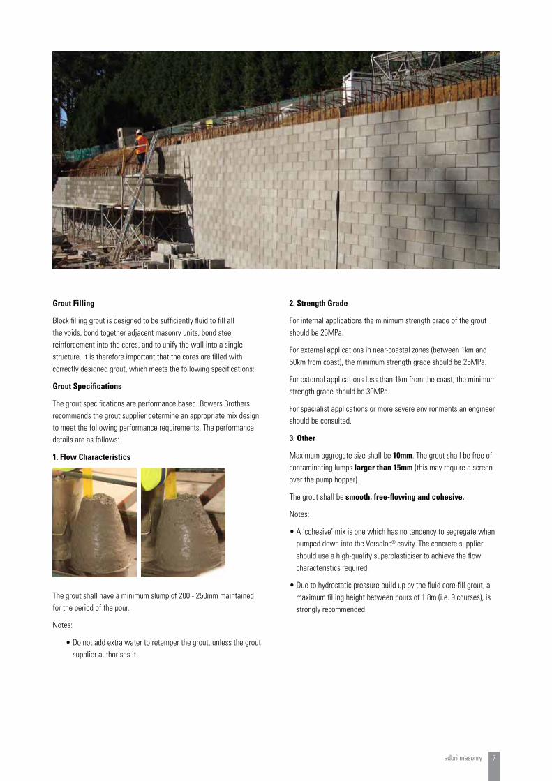
Grout Filling
Block filling grout is designed to be sufficiently fluid to fill all the voids, bond together adjacent masonry units, bond steel reinforcement into the cores, and to unify the wall into a single structure. It is therefore important that the cores are filled with correctly designed grout, which meets the following specifications:
Grout Specifications
The grout specifications are performance based. Bowers Brothers recommends the grout supplier determine an appropriate mix design to meet the following performance requirements. The performance details are as follows:
1. Flow Characteristics
The grout shall have a minimum slump of 200 - 250mm maintained for the period of the pour.
Notes:
• Do not add extra water to retemper the grout, unless the grout supplier authorises it.
2. Strength Grade
For internal applications the minimum strength grade of the grout should be 25MPa.
For external applications in near-coastal zones (between 1km and 50km from coast), the minimum strength grade should be 25MPa.
For external applications less than 1km from the coast, the minimum strength grade should be 30MPa.
For specialist applications or more severe environments an engineer should be consulted.
3. Other
Maximum aggregate size shall be 10mm. The grout shall be free of contaminating lumps larger than 15mm (this may require a screen over the pump hopper).
The grout shall be smooth, free-flowing and cohesive.
Notes:
• A ‘cohesive’ mix is one which has no tendency to segregate when pumped down into the Versaloc® cavity. The concrete supplier should use a high-quality superplasticiser to achieve the flow characteristics required.
• Due to hydrostatic pressure build up by the fluid core-fill grout, a maximum filling height between pours of 1.8m (i.e. 9 courses), is strongly recommended.
8 adbri masonry
adbri masonry 9
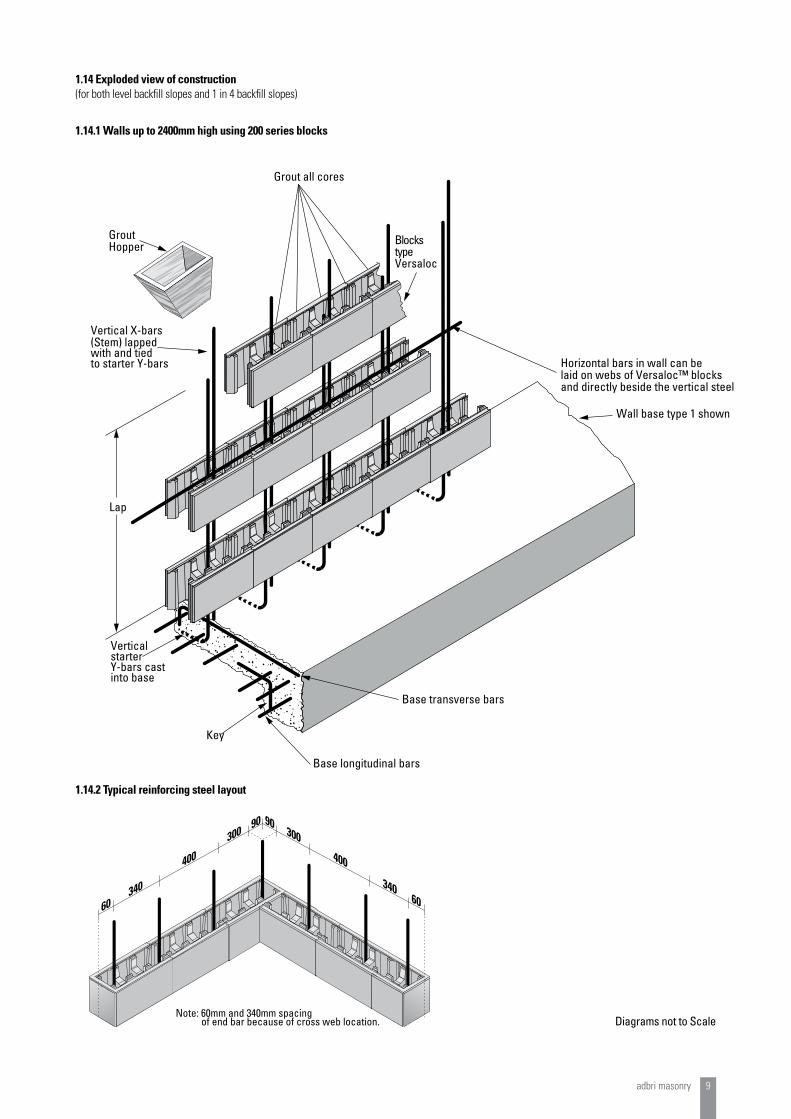
1.14 Exploded view of construction (for both level backfill slopes and 1 in 4 backfill slopes)
1.14.1 Walls up to 2400mm high using 200 series blocks
Horizontal bars in wall can belaid on webs of Versaloc™ blocksand directly beside the vertical steel
Wall base type 1 shown
Grout all cores
GroutHopper
Vertical X-bars(Stem) lappedwith and tiedto starter Y-bars
Lap
VerticalstarterY-bars castinto base
Key
Base longitudinal bars
Base transverse bars
Blocks typeVersaloc
90300
400
3406060
340
400
30090
Note: 60mm and 340mm spacing of end bar because of cross web location.
1.14.2 Typical reinforcing steel layout
Diagrams not to Scale
10 adbri masonry
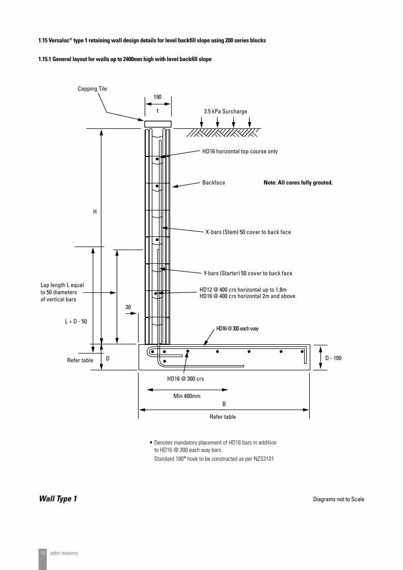
1.15 Versaloc® type 1 retaining wall design details for level backfill slope using 200 series blocks
1.15.1 General layout for walls up to 2400mm high with level backfill slope
Wall Type 1
190
t
X-bars (Stem) 50 cover to back face
Y-bars (Starter) 50 cover to back face
HD16 @ 300 each way
HD16 @ 300 crs
B
Refer table
Refer table
30
H
D
Capping Tile
HD16 horizontal top course only
Backface Note: All cores fully grouted.
HD12 @ 400 crs horizontal up to 1.8m
2.5 kPa Surcharge
HD16 @ 400 crs horizontal 2m and above
Lap length L equalto 50 diametersof vertical bars
L + D - 50
D - 100
Min 400mm
Diagrams not to Scale
• Denotes mandatory placement of HD16 bars in addition to HD16 @ 300 each way bars. Standard 180° hook to be constructed as per NZS3101

adbri masonry 11
Wall Height H
(mm)
Wall Width t
(mm)
Base Width B
(mm)
Base Depth D
(mm)
Key Width W
(mm)
Key Depth d
(mm)
Backfill Slope
Reinforcements
X-bars (Stem) Y-bars (Starter)
2400 190 1800 350 - - level HD16 at 400 HD20 at 400
2200 190 1700 350 - - level HD16 at 400 HD16 at 200
2000 190 1500 350 - - level HD16 at 400 HD16 at 200
1800 190 1500 250 - - level HD16 at 400 HD16 at 400
1600 190 1200 250 - - level HD16 at 400 HD16 at 400
1400 190 1000 250 - - level HD12 at 400 HD12 at 400
1200 190 900 200 - - level HD12 at 400 HD12 at 400
1000 190 800 200 - - level HD12 at 400 HD12 at 400
800 190 700 200 - - level HD12 at 400 HD12 at 400
600 190 600 200 - - level HD12 at 400 HD12 at 400
1.15.2 Design details for walls up to 2400mm high with level backfill slope
Characteristic internal friction angle of backfill material and retained soil 30° Characteristic internal friction angle of foundation 30°
Notes:
1) Cohesion is difficult to predict, is variable, may change over time, and is dependent on the effectiveness of surface sealing, surface drainage and subsurface drainage. These details are based on the assumption that drained and undrained cohesion (as appropriate) is assumed to be zero for active forces. Consideration must also be given to shrink/swell action of clay soils.
2) These details have been calculated on the basis of a rough interface between the base and the foundation soil, for which the external angle of friction, °, equals the internal angle of friction, °. The footing/foundation interface should be constructed such that this assumption is correct. The designer should consider the validity of this assumption.
3) A 2.5kPa surcharge applies.
4) All wall starter and stem reinforcing bars are located with 50mm cover to the back face of block.
5) All base and key reinforcing bars are to have 50mm clear cover to steel from face of concrete.
6) All footings to be founded on “Good Ground” as defined in Section 1.12
Wall Type 1

12 adbri masonry
1.16 Versaloc® type 1 retaining wall design details for 1:4 backfill slope using 200 series blocks
1.16.1 General layout for walls up to 1800mm high with 1:4 backfill slope
Wall Type 1
190
t
X-bars (Stem) 50 cover to back face
Y-bars (Starter) 50 cover to back face
HD12 @ 400 crs horizontal up to 1.4m high
HD16 @ 300 each way
min 400mmHD16 @ 300 crs
WB
Refer table
Refer table
D
H
d
30
HD12 horizontal top course only
Back face
Note: All cores fully grouted.
Capping Tile2.5 kPa Surcharge
HD16 @ 400 crs horizontal @ 1.6m high and above
Lap length L equalto 50 diametersof vertical bars
L + D - 50
D - 100
B - 100
W - 100
D + d - 100
Diagrams not to Scale
• Denotes mandatory placement of HD16 bars in addition to HD16 @ 300 each way bars. Standard 180° hook to be constructed as per NZS3101
adbri masonry 13
Wall Height H
(mm)
Wall Width t
(mm)
Base Width B
(mm)
Base Depth D
(mm)
Key Width W
(mm)
Key Depth d
(mm)
Backfill Slope
Reinforcements
X-bars (Stem) Y-bars (Starter)
1800 190 2400 250 200 200 1:4 HD16 at 400 HD20 at 400
1600 190 2300 250 200 200 1:4 HD12 at 400 HD16 at 400
1400 190 1500 250 - - 1:4 HD12 at 400 HD12 at 400
1200 190 1300 200 - - 1:4 HD12 at 400 HD12 at 400
1000 190 1200 200 - - 1:4 HD12 at 400 HD12 at 400
800 190 1000 200 - - 1:4 HD12 at 400 HD12 at 400
600 190 800 200 - - 1:4 HD12 at 400 HD12 at 400
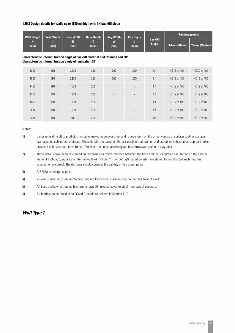
1.16.2 Design details for walls up to 1800mm high with 1:4 backfill slope
Characteristic internal friction angle of backfill material and retained soil 30° Characteristic internal friction angle of foundation 30°
Notes:
1) Cohesion is difficult to predict, is variable, may change over time, and is dependent on the effectiveness of surface sealing, surface drainage and subsurface drainage. These details are based on the assumption that drained and undrained cohesion (as appropriate) is assumed to be zero for active forces. Consideration must also be given to shrink/swell action of clay soils.
2) These details have been calculated on the basis of a rough interface between the base and the foundation soil, for which the external angle of friction, °, equals the internal angle of friction, °. The footing/foundation interface should be constructed such that this assumption is correct. The designer should consider the validity of this assumption.
3) A 2.5kPa surcharge applies.
4) All wall starter and stem reinforcing bars are located with 50mm cover to the back face of block.
5) All base and key reinforcing bars are to have 50mm clear cover to steel from face of concrete.
6) All footings to be founded on “Good Ground” as defined in Section 1.12.
Wall Type 1

14 adbri masonry
1.17 Versaloc® type 2 retaining wall design details for level backfill slope using 200 series blocks
1.17.1 General layout for walls up to 1800mm high with level backfill slope
Wall Type 2
190
t
X-bars (Stem) 50 cover to back face
HD12 @ 400 crs horizontal to 1.4m high
Y-bars (Starter) 50 cover to back face
Y-bars @ 50 cover
HD16 @ 300 crs
HD16 bars @
H
Refer table
D
B
W
Refer table
d
Back face
700lap
30
HD16 horizontal top course only
Note: All cores fully grouted.
Capping Tile
2.5 kPa Surcharge
HD16 @ 400 crs horizontal to 1.6m high and above
300 each way
HD16
Length = B - 100
(L = 50 x bar diameter)
L +
D - 5
0
Diagrams not to Scale
• Denotes mandatory placement of HD16 bars in addition to HD16 @ 300 each way bars. Standard 180° hook to be constructed as per NZS3101
adbri masonry 15
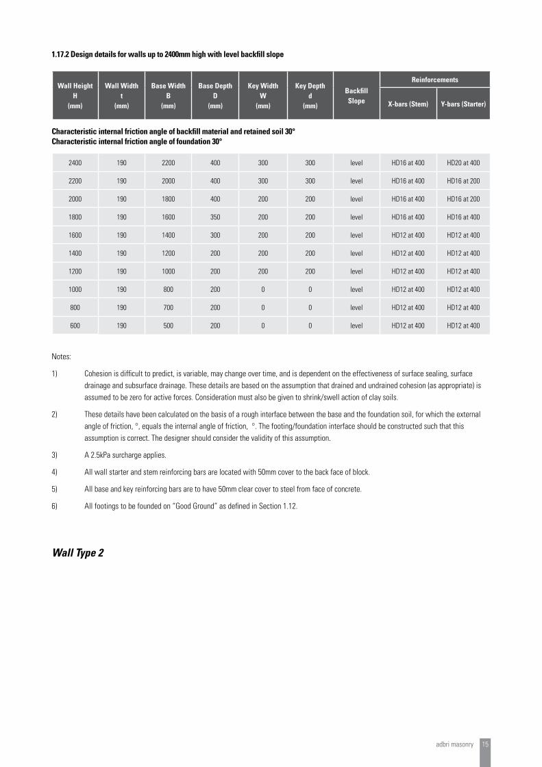
1.17.2 Design details for walls up to 2400mm high with level backfill slope
Notes:
1) Cohesion is difficult to predict, is variable, may change over time, and is dependent on the effectiveness of surface sealing, surface drainage and subsurface drainage. These details are based on the assumption that drained and undrained cohesion (as appropriate) is assumed to be zero for active forces. Consideration must also be given to shrink/swell action of clay soils.
2) These details have been calculated on the basis of a rough interface between the base and the foundation soil, for which the external angle of friction, °, equals the internal angle of friction, °. The footing/foundation interface should be constructed such that this assumption is correct. The designer should consider the validity of this assumption.
3) A 2.5kPa surcharge applies.
4) All wall starter and stem reinforcing bars are located with 50mm cover to the back face of block.
5) All base and key reinforcing bars are to have 50mm clear cover to steel from face of concrete.
6) All footings to be founded on “Good Ground” as defined in Section 1.12.
Wall Height H
(mm)
Wall Width t
(mm)
Base Width B
(mm)
Base Depth D
(mm)
Key Width W
(mm)
Key Depth d
(mm)
Backfill Slope
Reinforcements
X-bars (Stem) Y-bars (Starter)
2400 190 2200 400 300 300 level HD16 at 400 HD20 at 400
2200 190 2000 400 300 300 level HD16 at 400 HD16 at 200
2000 190 1800 400 200 200 level HD16 at 400 HD16 at 200
1800 190 1600 350 200 200 level HD16 at 400 HD16 at 400
1600 190 1400 300 200 200 level HD12 at 400 HD12 at 400
1400 190 1200 200 200 200 level HD12 at 400 HD12 at 400
1200 190 1000 200 200 200 level HD12 at 400 HD12 at 400
1000 190 800 200 0 0 level HD12 at 400 HD12 at 400
800 190 700 200 0 0 level HD12 at 400 HD12 at 400
600 190 500 200 0 0 level HD12 at 400 HD12 at 400
Characteristic internal friction angle of backfill material and retained soil 30° Characteristic internal friction angle of foundation 30°
Wall Type 2
16 adbri masonry
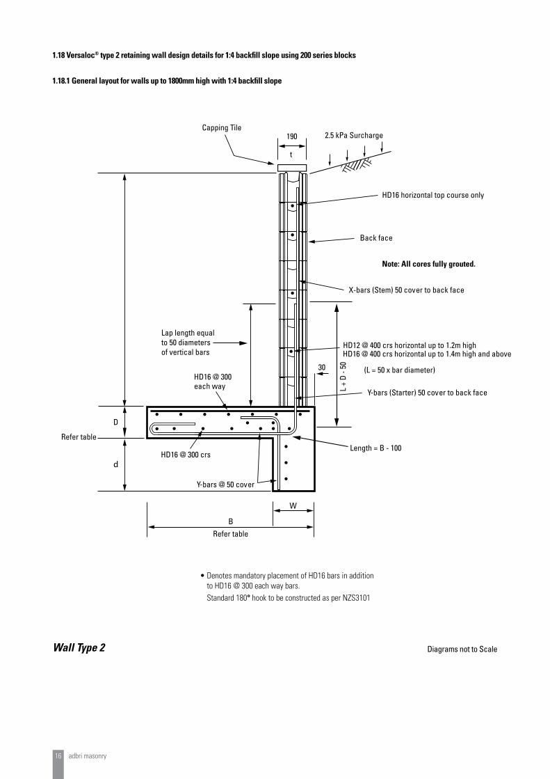
1.18 Versaloc® type 2 retaining wall design details for 1:4 backfill slope using 200 series blocks
1.18.1 General layout for walls up to 1800mm high with 1:4 backfill slope
Wall Type 2
190 2.5 kPa Surcharge
t
X-bars (Stem) 50 cover to back face
HD12 @ 400 crs horizontal up to 1.2m high
Y-bars (Starter) 50 cover to back face
Y-bars @ 50 cover
HD16 @ 300
HD16 @ 300 crs
Refer tableB
W
Refer table
D
d
Back face
HD16 horizontal top course only
Note: All cores fully grouted.
30
Capping Tile
HD16 @ 400 crs horizontal up to 1.4m high and above
Lap length equalto 50 diametersof vertical bars
each way
Length = B - 100
L +
D - 5
0
(L = 50 x bar diameter)
Diagrams not to Scale
• Denotes mandatory placement of HD16 bars in addition to HD16 @ 300 each way bars. Standard 180° hook to be constructed as per NZS3101

adbri masonry 17
1.18.2 Design details for walls up to 1800mm high with 1:4 backfill slope
Notes:
1) Cohesion is difficult to predict, is variable, may change over time, and is dependent on the effectiveness of surface sealing, surface drainage and subsurface drainage. These details are based on the assumption that drained and undrained cohesion (as appropriate) is assumed to be zero for active forces. Consideration must also be given to shrink/swell action of clay soils.
2) These details have been calculated on the basis of a rough interface between the base and the foundation soil, for which the external angle of friction, °, equals the internal angle of friction, °. The footing/foundation interface should be constructed such that this assumption is correct. The designer should consider the validity of this assumption.
3) A 2.5kPa surcharge applies.
4) All wall starter and stem reinforcing bars are located with 50mm cover to the back face of block.
5) All base and key reinforcing bars are to have 50mm clear cover to steel from face of concrete.
6) All footings to be founded on “Good Ground” as defined in Section 1.12.
Wall Type 2
Wall Height H
(mm)
Wall Width t
(mm)
Base Width B
(mm)
Base Depth D
(mm)
Key Width W
(mm)
Key Depth d
(mm)
Backfill Slope
Reinforcements
X-bars (Stem) Y-bars (Starter)
1800 190 2200 350 300 300 1:4 HD16 at 400 HD20 at 400
1600 190 2000 300 200 200 1:4 HD16 at 400 HD16 at 200
1400 190 1700 300 200 200 1:4 HD12 at 400 HD12 at 400
1200 190 1400 300 0 0 1:4 HD12 at 400 HD12 at 400
1000 190 1100 200 0 0 1:4 HD12 at 400 HD12 at 400
800 190 800 200 0 0 1:4 HD12 at 400 HD12 at 400
600 190 600 200 0 0 1:4 HD12 at 400 HD12 at 400
Characteristic internal friction angle of backfill material and retained soil 30° Characteristic internal friction angle of foundation 30°
18 adbri masonry
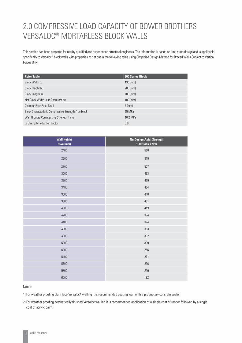
Wall Height Hwe (mm)
Nu Design Axial Strength 190 Block kN/m
2400 530
2600 519
2800 507
3000 493
3200 479
3400 464
3600 448
3800 431
4000 413
4200 394
4400 374
4600 353
4800 332
5000 309
5200 286
5400 261
5600 236
5800 210
6000 182
Notes:
1) For weather proofing plain face Versaloc® walling it is recommended coating wall with a proprietary concrete sealer.
2) For weather proofing aesthetically finished Versaloc walling it is recommended application of a single coat of render followed by a single coat of acrylic paint.
This section has been prepared for use by qualified and experienced structural engineers. The information is based on limit state design and is applicable specifically to Versaloc® block walls with properties as set out in the following table using Simplified Design Method for Braced Walls Subject to Vertical Forces Only.
2.0 COMPRESSIVE LOAD CAPACITY OF BOWER BROTHERS VERSALOC® MORTARLESS BLOCK WALLS
Refer Table 200 Series Block
Block Width tu 190 (mm)
Block Height hu 200 (mm)
Block Length lu 400 (mm)
Net Block Width Less Chamfers tw 180 (mm)
Chamfer Each Face Shell 5 (mm)
Block Characteristic Compressive Strength f’ uc block 25 MPa
Wall Grouted Compressive Strength f’ mg 10.2 MPa
ø Strength Reduction Factor 0.6
adbri masonry 19
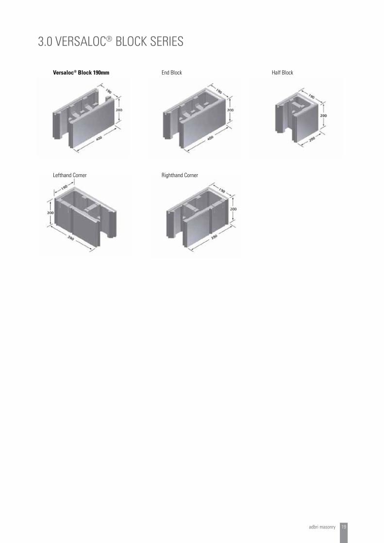
Versaloc® Block 190mm End Block Half Block
Lefthand Corner Righthand Corner
3.0 VERSALOC® BLOCK SERIES

Speak to us now about all your masonry requirements!
Morrinsville 51 Lorne Street
P - 0800 207374P - 07 889 6774F - 07 889 3177
www.bowersbrothers.co.nz
Versaloc® is a registered trademark of Adbri Masonry used under exclusive licence.


