INSTRUCTION MANUAL
SYSTEM MANAGEMENT AMPLIFIER
REMOTE MICROPHONE
REMOTE MICROPHONE EXTENSION
VOICE ANNOUNCEMENT BOARD
SURVEILLANCE BOARD
VM-2120 (120 W)VM-2240 (240 W)
RM-200M
RM-210
EV-200M
SV-200MA
VM-2120
RM-200M
Please follow the instructions in this manual to obtain the optimum results from this unit.We also recommend that you keep this manual handy for future reference.
2
TABLE OF CONTENTS
1. SAFETY PRECAUTIONS ..................................................................................... 4
2. GENERAL DESCRIPTION ................................................................................... 6
3. FEATURES ............................................................................................................. 6
4. HANDLING PRECAUTIONS ............................................................................... 7
5. INSTALLATION PRECAUTIONS ........................................................................ 7
6. NOMENCLATURE AND FUNCTIONS 6.1. System Management Amplifier VM-2120/-2240 ............................................... 86.2. Remote Microphone RM-200M ....................................................................... 126.3. Remote Microphone Extension RM-210 ......................................................... 13
7. SYSTEM CONFIGURATIONS 7.1. Remote Microphone/VM Amplifier Configuration
(The Number of Connected Units) .................................................................... 147.2. Remote Microphone Operation Panel Function ............................................... 147.3. Connection between Remote Microphone and VM Amplifier .......................... 157.4. Power Supply from the VM Amplifier to Remote Microphone .......................... 16
8. EMERGENCY ("ALERT" AND "EVACUATION") BROADCAST8.1. Emergency Broadcast Equipment .................................................................. 178.2. Keys/Indicators Used for Emergency Broadcast ............................................ 178.3. Emergency Broadcast Operation (Typical Example) ...................................... 188.4. Emergency Broadcast Sequence ................................................................... 20
9. BROADCAST OPERATION AT THE AMPLIFIER 9.1. Microphone Announcements (When Operated by Control Input) .................... 219.2. Background Music Broadcast .......................................................................... 21
10. REMOTE MICROPHONE GENERAL-PURPOSE BROADCAST10.1. Operation and Display Sections ..................................................................... 2210.2. Broadcast Operation ...................................................................................... 23
11. GENERAL-PURPOSE BROADCAST PRIORITY 11.1. Broadcast Source-to-Priority Relationship ..................................................... 2611.2. Broadcast Priority between Equipment with the Equal Priority Level
11.2.1. Priority mode between equipment with the equal priority level .......... 2711.2.2. Priority function when 2 broadcasts
with the equal priority level are simultaneously made ....................... 2811.3. Priority Function during BGM Broadcast ........................................................ 28
12. CHIME FUNCTION 12.1. Available Chime Tone Types
12.1.1. Five different chime tones .................................................................. 2912.1.2. Four built-in chimes ............................................................................ 2912.1.3. Pre-recorded chime ........................................................................... 29
12.2. How the Chime Tone Is Used 12.2.1. Chime tone for Inputs 1 – 3 ................................................................ 2912.2.2. Telephone paging chime tone ............................................................ 2912.2.3. Independent chime activation (remote control) .................................. 30
13. CHOKE COIL INSTALLATION .......................................................................... 31
14. INPUT TRANSFORMER INSTALLATION AND ITS BOARD MODIFICATION ............................................................................ 31
15. MOUNTING AN OPTIONAL EV-200M VOICE ANNOUNCEMENT BOARD ................................................ 31
AMPLIFIER INSTALLATION
OPERATIONS
EQUIPMENT OUTLINES
3
16. MOUNTING AN OPTIONAL SV-200MA SURVEILLANCE BOARD .............................................................. 31
17. RACK MOUNTING .............................................................................................. 32
18. AMPLIFIER INPUT CONNECTION 18.1. Two Amplifiers Stack-Connection .................................................................. 3218.2. Microphone Connection to the VM Amplifier .................................................. 3218.3. Telephone Paging Input Connections ............................................................ 33
19. EXTERNAL ATTENUATOR CONTROL WIRING 19.1. 4-Wire System Connection ............................................................................ 3419.2. 3-Wire System Connection ............................................................................ 35
20. CHANGING THE SPEAKER LINE VOLTAGE ................................................ 35
21. CONTROL I/O CONNECTOR FUNCTIONS ................................................... 36
22. SURVEILLANCE I/O CONNECTOR FUNCTIONS ........................................ 38
23. FUNCTION SWITCH OPERATION23.1. VM Amplifier's Rear Panel-Mounted Function Switches ................................ 3923.2. VM Amplifier's Internal Function Switches ..................................................... 4023.3. Remote Microphone's Function Switches ...................................................... 40
24. BROADCAST GROUP/ZONE SETTING 24.1. Routing Assignment
24.1.1. Zone-to-Group assignment ................................................................ 4124.1.2. Control input/Telephone paging-to-Group assignment ...................... 4124.1.3. Recorded Message-to-Group assignment ......................................... 42
24.2. Operating Keys .............................................................................................. 4224.3. Zone-to-Group Assignment Operation ........................................................... 4324.4. Control Input/Telephone Paging-to-Group Assignment Operation ................ 4624.5. Recorded Message-to-Group Assignment Operation .................................... 48
25. LINKAGE BETWEEN REMOTE MICROPHONE AND ITS EXTENSION ........................................................................................ 49
26. NAME LABEL PREPARATION 26.1. Amplifier's Label Preparation ......................................................................... 5026.2. Remote Microphone's Label Preparation
26.2.1. Name label type and usable paper .................................................... 5026.2.2. Preparing the name label ................................................................... 5026.2.3. Inserting the name label ..................................................................... 50
27. COMPACTFLASH (CF) CARD RECORDING 27.1. Recording ....................................................................................................... 5327.2. Message Program/Sentence Composition Example ..................................... 5327.3. Message Program Example ........................................................................... 54
28. BLOCK DIAGRAM .............................................................................................. 55
29. SPECIFICATIONS System Management Amplifier VM-2120/-2240 ..................................................... 56Remote Microphone RM-200M ............................................................................... 59Remote Microphone Extension RM-210 ................................................................. 59Voice Announcement Board EV-200M ................................................................... 60Surveillance Board SV-200MA ................................................................................ 60
MISCELLANEOUS
REMOTE MICROPHONE INSTALLATION
SETTINGS
AMPLIFIER CONNECTIONS
4
When Installing the Unit
[Applicable to all models]
• Do not expose the unit to rain or an environmentwhere it may be splashed by water or other liquids,as doing so may result in fire or electric shock.
• Use the unit only with the voltage specified on theunit. Using a voltage higher than that which isspecified may result in fire or electric shock.
• Avoid installing or mounting the unit in unstablelocations, such as on a rickety table or a slantedsurface. Doing so may result in the unit fallingdown and causing personal injury and/or propertydamage.
[Applicable to the VM-2120/-2240]
• Do not cut, kink, otherwise damage nor modify thepower supply cord. In addition, avoid using thepower cord in close proximity to heaters, and neverplace heavy objects – including the unit itself – onthe power cord, as doing so may result in fire orelectric shock.
• The apparatus shall be connected to a mainssocket outlet with a protective earthing connection.
• The socket-outlet shall be installed near theequipment and the plug (disconnecting device)shall be easily accessible.
[Applicable to the RM-200M/-210]
• Install the unit only in a location that canstructurally support the weight of the unit and themounting bracket. Doing otherwise may result inthe unit falling down and causing personal injuryand/or property damage.
• Do not use other methods than specified to mountthe bracket. Extreme force is applied to the unitand the unit could fall off, possibly resulting inpersonal injuries.
• Use nuts and bolts that are appropriate for theceiling's or wall's structure and composition. Failureto do so may cause the unit to fall, resulting inmaterial damage and possible personal injury.
When the Unit is in Use
[Applicable to all models]
• To prevent a fire or electric shock, never open norremove the unit case as there are high voltagecomponents inside the unit. Refer all servicing toyour nearest TOA dealer.
• Do not place cups, bowls, or other containers ofliquid or metallic objects on top of the unit. If theyaccidentally spill into the unit, this may cause a fireor electric shock.
• Do not insert metallic objects such as pointedobjects and coins, or flammable materials in theunit's openings, as this may result in fire or electricshock.
• Do not touch a plug during thunder and lightning,as this may result in electric shock.
1. SAFETY PRECAUTIONS
• Be sure to read the instructions in this section carefully before use.• Make sure to observe the instructions in this manual as the conventions of safety symbols and messages
regarded as very important precautions are included.• We also recommend you keep this instruction manual handy for future reference.
Safety Symbol and Message Conventions Safety symbols and messages described below are used in this manual to prevent bodily injury and propertydamage which could result from mishandling. Before operating your product, read this manual first andunderstand the safety symbols and messages so you are thoroughly aware of the potential safety hazards.
Indicates a potentially hazardous situation which, if mishandled, couldresult in death or serious personal injury.
Indicates a potentially hazardous situation which, if mishandled, couldresult in moderate or minor personal injury, and/or property damage.
WARNING
CAUTION
WARNING
5
[Applicable to the VM-2120/-2240]
• Should the following irregularity be found duringuse, immediately switch off the power, disconnectthe power supply plug from the AC outlet andcontact your nearest TOA dealer. Make no furtherattempt to operate the unit in this condition as thismay cause fire or electric shock.
· If you detect smoke or a strange smell comingfrom the unit.
· If water or any metallic object gets into the unit · If the unit falls, or the unit case breaks · If the power supply cord is damaged (exposure of
the core, disconnection, etc.)· If it is malfunctioning (no tone sounds.)
• When replacing the fuse, be sure to use thesupplied one. Using any other fuse than suppliedmay cause fire or electric shock.
When Installing the Unit
[Applicable to all models]
• Avoid installing the unit in humid or dusty locations,in locations exposed to the direct sunlight, near theheaters, or in locations generating sooty smoke orsteam as doing otherwise may result in fire orelectric shock.
[Applicable to the VM-2120/-2240]
• Never plug in nor remove the power supply plugwith wet hands, as doing so may cause electricshock.
• When unplugging the power supply cord, be sureto grasp the power supply plug; never pull on thecord itself. Operating the unit with a damagedpower supply cord may cause a fire or electricshock.
• When moving the unit, be sure to remove its powersupply cord from the wall outlet. Moving the unitwith the power cord connected to the outlet maycause damage to the power cord, resulting in fire orelectric shock. When removing the power cord, besure to hold its plug to pull.
• Do not block the ventilation slots in the unit's cover.Doing so may cause heat to build up inside the unitand result in fire.
• To avoid electric shocks, be sure to unplug theunit 's power supply cord when connectingspeakers.
When the Unit is in Use
[Applicable to all models]
• Do not place heavy objects on the unit as this maycause it to fall or break which may result inpersonal injury and/or property damage. Inaddition, the object itself may fall off and causeinjury and/or damage.
[Applicable to the VM-2120/-2240]
• Make sure that the volume control is set tominimum position before power is switched on.Loud noise produced at high volume when power isswitched on can impair hearing.
• Do not operate the unit for an extended period oftime with the sound distorting. This is an indicationof a malfunction, which in turn can cause heat togenerate and result in a fire.
• Contact your TOA dealer as to the cleaning. If dustis allowed to accumulate in the unit over a longperiod of time, a fire or damage to the unit mayresult.
• If dust accumulates on the power supply plug or inthe wall AC outlet, a fire may result. Clean itperiodically. In addition, insert the plug in the walloutlet securely.
• Switch off the power, and unplug the power supplyplug from the AC outlet for safety purposes whencleaning or leaving the unit unused for 10 days ormore. Doing otherwise may cause a fire or electricshock.
CAUTION
[Applicable to the VM-2120/-2240]
An all-pole mains switch with a contact separation of at least 3 mm in each pole shall be incorporated inthe electrical installation of the building.
[Applicable to the VM-2120/-2240 and RM-200M]
The socket-outlet shall be installed near the equipment and the plug (disconnecting device) shall beeasily accessible.
6
2. GENERAL DESCRIPTION
[System Management Amplifier VM-2120/VM-2240]
Featuring outstanding audio performance, the TOA System Management Amplifier VM-2120/-2240 satisfiesthe growing need for reliable and efficient communications for various applications, especially for medium-sized facilities including office building, factories, hospitals, and transportation terminals.
The VM-2120 (120 W) and VM-2240 (240 W) are multifunctional amplifiers that can be mounted in an EIA-Standard equipment rack (3-unit size). Both units come with 4 audio inputs including the background musicinput, and the speaker output section which has an internal attenuator and 5-zone selector. They permit notonly general-purpose broadcast, but also Emergency Broadcast based on the EN60849 Standard which givespre-recorded voice instructions*1 in the emergency situation. Broadcast can be made from an optional RM-200M Remote Microphone as well as from the amplifier, and can be remotely controlled from externalequipment. In addition, both amplifiers feature the surveillance function*2 which automatically checks thesystem for failures.
*1 An optional EV-200M Voice Announcement Board is required. *2 An optional SV-200MA Surveillance Board is required.
[Remote Microphone RM-200M]
The RM-200M is a dedicated unit for both the VM-2120 and VM-2240, and permits Emergency Broadcast aswell as general-purpose broadcast.
[Remote Microphone Extension RM-210]
The RM-210 is an extension unit for the RM-200M's key operating section.
3. FEATURES
• Broadcasts of up to 480 W can be made to up to 10 zones individually or simultaneously. (when 2 VM-2240's are used).
• Permits monitoring of individual speaker line or power amplifier failures for status indication. (Requires the optional SV-200MA Surveillance Board.)
• Reproduces 5 general-purpose messages, 1 chime tone, and 2 emergency messages. (Recordable as you like using the optional EV-200M Voice Announcement Board)
• Four different built-in chimes and prerecorded chime tones (by the EV-200M) can be selected to attractattention to broadcasts.
• Backup battery maintains operation during power failures.
• Emergency broadcast based on the EN60849 Standard provides prerecorded voice instructions in theemergency situation.
• Emergency broadcast bypasses both the amplifier volume control and the external attenuator, making surethat the broadcast is heard throughout all zones.
• Features following broadcast priority levels: the highest level for Emergency broadcasts and 4 levels forgeneral-purpose broadcasts.
• Speaker lines for 100 V line applications (standard) or for 50 V or 70 V line applications (enabled bychanging the unit's internal wiring).
• Up to 4 remote microphones can be connected, and their total connection cables can be extended to 800 m.(RM-200M/-210)
• Speaker zones can be programmed into up to 5 groups for group broadcast. (The remote microphone can broadcast to the Groups 1 and 2 out of the 5 groups.)
• Clear, distortion-free announcements owing to the internal compressor circuitry. (RM-200M/-210)
7
4. HANDLING PRECAUTIONS
[VM-2120/VM-2240 and RM-200M/RM-210] To clean, be sure to first switch off the power supply to the unit, then wipe with a dry cloth. When the unit getsvery dirty, use a cloth damped in a neutral cleanser. Never use benzene, thinner or chemically-treatedcleaning cloth because such volatile liquids could deform or discolor the unit.
[VM-2120/VM-2240] • When the EV-200M is mounted, never move the unit from one place to another with the Flash Card inserted
because the EV-200M or the CompactFlash card may fail.
• Avoid inserting or withdrawing the CompactFlash card while the unit is alive.
5. INSTALLATION PRECAUTIONS
[VM-2120/VM-2240 and RM-200M/RM-210] • Do not install the unit in locations exposed to the direct sunlight or heaters, as the unit could be deformed or
discolored.
• Avoid installing or storing the unit in dusty or humid locations, as doing otherwise could cause the unit'sfailure.
• Keep the unit as far away as possible from a fluorescent lamp, digital equipment, PC or other equipmentwhich generate high frequency noise.
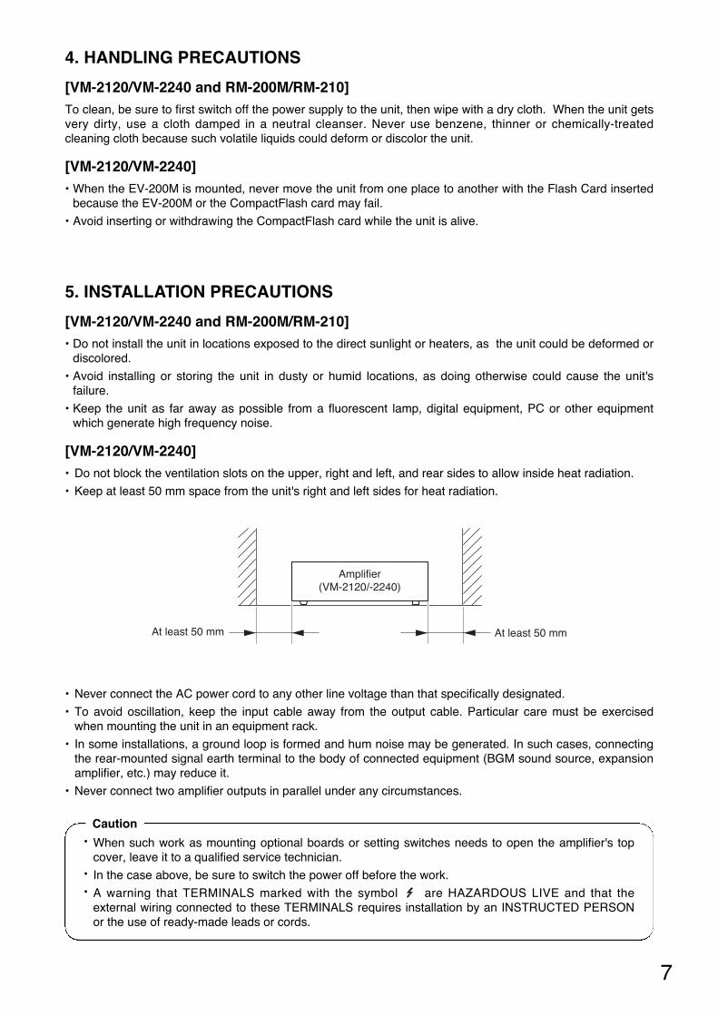
[VM-2120/VM-2240] • Do not block the ventilation slots on the upper, right and left, and rear sides to allow inside heat radiation.
• Keep at least 50 mm space from the unit's right and left sides for heat radiation.
• Never connect the AC power cord to any other line voltage than that specifically designated.
• To avoid oscillation, keep the input cable away from the output cable. Particular care must be exercisedwhen mounting the unit in an equipment rack.
• In some installations, a ground loop is formed and hum noise may be generated. In such cases, connectingthe rear-mounted signal earth terminal to the body of connected equipment (BGM sound source, expansionamplifier, etc.) may reduce it.
• Never connect two amplifier outputs in parallel under any circumstances.
Amplifier(VM-2120/-2240)
At least 50 mm At least 50 mm
• When such work as mounting optional boards or setting switches needs to open the amplifier's topcover, leave it to a qualified service technician.
• In the case above, be sure to switch the power off before the work. • A warning that TERMINALS marked with the symbol are HAZARDOUS LIVE and that the
external wiring connected to these TERMINALS requires installation by an INSTRUCTED PERSONor the use of ready-made leads or cords.
Caution
8
1289
1
2
15
16
13 146 7 10 1111
3
4
5
6. NOMENCLATURE AND FUNCTIONS
6.1. System Management Amplifier VM-2120/-2240
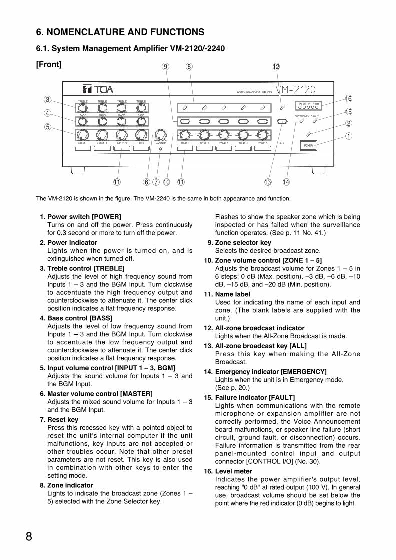
[Front]
1. Power switch [POWER] Turns on and off the power. Press continuouslyfor 0.3 second or more to turn off the power.
2. Power indicator Lights when the power is turned on, and isextinguished when turned off.
3. Treble control [TREBLE] Adjusts the level of high frequency sound fromInputs 1 – 3 and the BGM Input. Turn clockwiseto accentuate the high frequency output andcounterclockwise to attenuate it. The center clickposition indicates a flat frequency response.
4. Bass control [BASS] Adjusts the level of low frequency sound fromInputs 1 – 3 and the BGM Input. Turn clockwiseto accentuate the low frequency output andcounterclockwise to attenuate it. The center clickposition indicates a flat frequency response.
5. Input volume control [INPUT 1 – 3, BGM] Adjusts the sound volume for Inputs 1 – 3 andthe BGM Input.
6. Master volume control [MASTER] Adjusts the mixed sound volume for Inputs 1 – 3and the BGM Input.
7. Reset key Press this recessed key with a pointed object toreset the unit's internal computer if the unitmalfunctions, key inputs are not accepted orother troubles occur. Note that other presetparameters are not reset. This key is also usedin combination with other keys to enter thesetting mode.
8. Zone indicator Lights to indicate the broadcast zone (Zones 1 –5) selected with the Zone Selector key.
Flashes to show the speaker zone which is beinginspected or has failed when the surveillancefunction operates. (See p. 11 No. 41.)
9. Zone selector key Selects the desired broadcast zone.
10. Zone volume control [ZONE 1 – 5] Adjusts the broadcast volume for Zones 1 – 5 in6 steps: 0 dB (Max. position), –3 dB, –6 dB, –10dB, –15 dB, and –20 dB (Min. position).
11. Name label Used for indicating the name of each input andzone. (The blank labels are supplied with theunit.)
12. All-zone broadcast indicator Lights when the All-Zone Broadcast is made.
13. All-zone broadcast key [ALL] Press this key when making the All-ZoneBroadcast.
14. Emergency indicator [EMERGENCY] Lights when the unit is in Emergency mode. (See p. 20.)
15. Failure indicator [FAULT] Lights when communications with the remotemicrophone or expansion amplifier are notcorrectly performed, the Voice Announcementboard malfunctions, or speaker line failure (shortcircuit, ground fault, or disconnection) occurs.Failure information is transmitted from the rearpanel-mounted control input and outputconnector [CONTROL I/O] (No. 30).
16. Level meter Indicates the power amplifier's output level,reaching "0 dB" at rated output (100 V). In generaluse, broadcast volume should be set below thepoint where the red indicator (0 dB) begins to light.
The VM-2120 is shown in the figure. The VM-2240 is the same in both appearance and function.
9
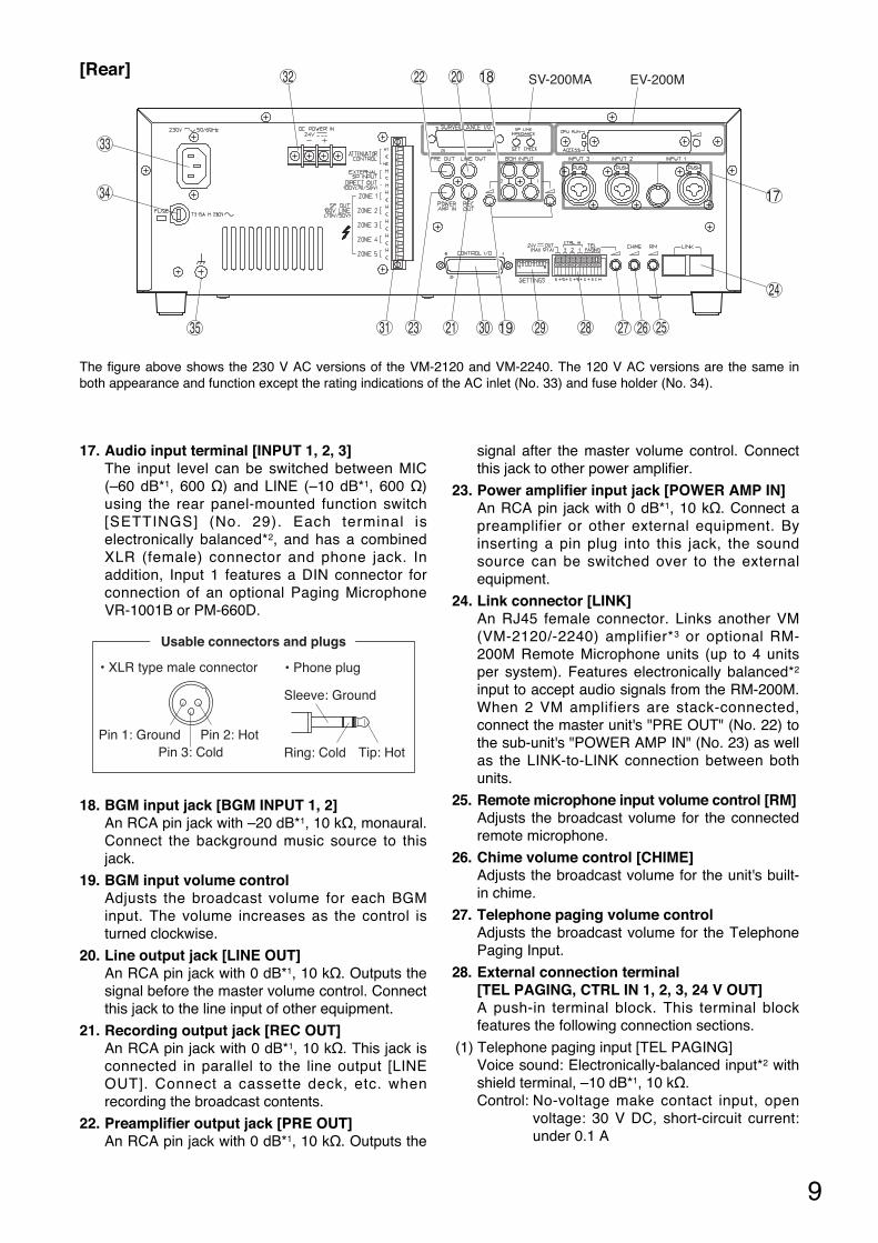
[Rear]
17. Audio input terminal [INPUT 1, 2, 3] The input level can be switched between MIC(–60 dB*1, 600 Ω) and LINE (–10 dB*1, 600 Ω)using the rear panel-mounted function switch[SETTINGS] (No. 29). Each terminal iselectronically balanced*2, and has a combinedXLR (female) connector and phone jack. Inaddition, Input 1 features a DIN connector forconnection of an optional Paging MicrophoneVR-1001B or PM-660D.
18. BGM input jack [BGM INPUT 1, 2] An RCA pin jack with –20 dB*1, 10 kΩ, monaural.Connect the background music source to thisjack.
19. BGM input volume control Adjusts the broadcast volume for each BGMinput. The volume increases as the control isturned clockwise.
20. Line output jack [LINE OUT] An RCA pin jack with 0 dB*1, 10 kΩ. Outputs thesignal before the master volume control. Connectthis jack to the line input of other equipment.
21. Recording output jack [REC OUT] An RCA pin jack with 0 dB*1, 10 kΩ. This jack isconnected in parallel to the line output [LINEOUT]. Connect a cassette deck, etc. whenrecording the broadcast contents.
22. Preamplifier output jack [PRE OUT] An RCA pin jack with 0 dB*1, 10 kΩ. Outputs the
signal after the master volume control. Connectthis jack to other power amplifier.
23. Power amplifier input jack [POWER AMP IN] An RCA pin jack with 0 dB*1, 10 kΩ. Connect apreamplifier or other external equipment. Byinserting a pin plug into this jack, the soundsource can be switched over to the externalequipment.
24. Link connector [LINK] An RJ45 female connector. Links another VM(VM-2120/-2240) amplifier*3 or optional RM-200M Remote Microphone units (up to 4 unitsper system). Features electronically balanced*2
input to accept audio signals from the RM-200M.When 2 VM amplifiers are stack-connected,connect the master unit's "PRE OUT" (No. 22) tothe sub-unit's "POWER AMP IN" (No. 23) as wellas the LINK-to-LINK connection between bothunits.
25. Remote microphone input volume control [RM] Adjusts the broadcast volume for the connectedremote microphone.
26. Chime volume control [CHIME] Adjusts the broadcast volume for the unit's built-in chime.
27. Telephone paging volume control Adjusts the broadcast volume for the TelephonePaging Input.
28. External connection terminal [TEL PAGING, CTRL IN 1, 2, 3, 24 V OUT] A push-in terminal block. This terminal blockfeatures the following connection sections.
(1) Telephone paging input [TEL PAGING] Voice sound: Electronically-balanced input*2 withshield terminal, –10 dB*1, 10 kΩ. Control: No-voltage make contact input, open
voltage: 30 V DC, short-circuit current:under 0.1 A
EV-200MSV-200MA
33
34
32 2022 18
24
35 31 2123 252627282930 19
17
Usable connectors and plugs
• XLR type male connector • Phone plug
Pin 1: Ground
Sleeve: Ground
Pin 2: HotTip: HotPin 3: Cold Ring: Cold
The figure above shows the 230 V AC versions of the VM-2120 and VM-2240. The 120 V AC versions are the same inboth appearance and function except the rating indications of the AC inlet (No. 33) and fuse holder (No. 34).
10
(2) Control input for broadcast activation [CTRL IN 1, 2, 3] 3 no-voltage make contact inputs, open voltage:3.3 V DC, short-circuit current: under 1 mA
(3) 24 V DC Power output [24 V OUT] Supplies the 24 V DC/0.1 A power to an optionalAmplifier Control Unit RU-2001/-2002.
29. Function switch [SETTINGS] An 8-bit DIP switch and selects
(1) Phantom power on-off for each input 1 – 3
(2) Telephone paging chime on-off
(3) 5 different types of chime tones [2-tone chime/4-tone chime (Up)/Single-tone chime/4-tone chime(Up & Down), and Pre-recorded chime*4], orchime-off
(4) MIC/LINE gain for inputs 1 – 3
Refer to page 39 "FUNCTION SWITCHOPERATION" for operation of the functionswitch.
30. Control input and output connector [CONTROL I/O] A 25-pin, female D-sub connector.
(1) External control inputThe following functions can be activated fromexternal equipment.
• Message for an optional Voice AnnouncementBoard
• Chime
• Power
• Emergency Broadcast
• Unit's broadcast cutoff
(2) Status output When the unit is placed in the following status,the corresponding output is at make.
• Irregularity of communications with the RemoteMicrophone and an expansion amplifier.
• AC power ON • DC power ON • Irregularity of the sound source of the Voice
Announcement Board. • Failure (FAULT) indication on • Power switch on
31. Attenuator control, external speaker input,speaker output connector [ATTENUATOR CONTROL, EXTERNAL SPINPUT, DIRECT OUT, ZONE 1 – 5] A dedicated, 16-pin plug-in screw connector andhas the following input and outputs.
(1) External attenuator control output [ATTENUATOR CONTROL] An output terminal for bypassing the externalattenuator.
(2) External speaker line Input [EXTERNAL SP INPUT] Accepts the signal from the external amplifier'sspeaker line. When the unit's broadcast cutoffinput terminal of the Control Input and OutputConnector (No. 30) is activated by an emergencyequipment, the unit's power amplifier output iscut off, allowing the external signal to go throughto the speakers in all zones.
(3) Direct speaker line output [DIRECT OUT] Outputs the signal directly from the poweramplifier transformer output.*5 The volume levelis the same as that which can be provided whenthe Zone Volume Control (No. 10) is set to themaximum position.
(4) Speaker output [SP OUT, ZONE 1 – 5] Connects to the speaker lines. This output is of100 V line type, but can be converted to the 50 Vor 70 V line type by internal connection change.
32. 24 V DC power input Connect the backup battery (maximum 24 VDC/7.5 A for VM-2120, 15 A for VM-2240) to thisterminal.
33. AC inlet [AC mains] Connect the supplied power cord to this inlet.
34. Fuse holder The following miniature fuses (20 mm type) areused.• 6.3 A
For VM-2120 (120 V AC version)• 8 A For VM-2240 (120 V AC version)
• T2.5 A of time lag type For VM-2120 (230 V AC version)
• T3.15 A of time lag type For VM-2240 (230 V AC version)
Note: When the fuse is blown off, first removethe cause, then replace with the correcttype specified on the unit.
35. Signal earth terminal Note this terminal is not a safety earth. Whenthere is hum noise, connecting this terminal tothe body of connected equipment (BGM soundsource, expansion amplifier, etc.) may reduce it.
*1 0 dB = 1 V
*2 Can be transformer-balanced with the additionof an optional IT-450 input transformer.
*3 Both the VM-2120 and the VM-2240 can alsobe combined.
*4 The chime sound source must be pre-recorded into a CF (CompactFlash) card to beinserted into the optional EV-200M VoiceAnnouncement Board. (See p. 11.)
*5 Output signal source is switched to theEXTERNAL SP INPUT if the unit's broadcastcutoff is activated. See No. 31 (2).
11
36
37
38
39
40
41 42 43
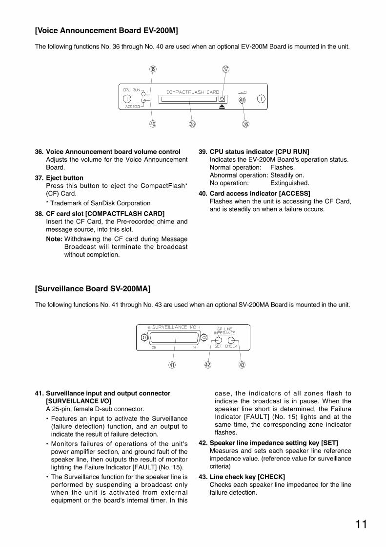
36. Voice Announcement board volume control Adjusts the volume for the Voice AnnouncementBoard.
37. Eject button Press this button to eject the CompactFlash*(CF) Card.
* Trademark of SanDisk Corporation
38. CF card slot [COMPACTFLASH CARD] Insert the CF Card, the Pre-recorded chime andmessage source, into this slot.
Note: Withdrawing the CF card during MessageBroadcast will terminate the broadcastwithout completion.
39. CPU status indicator [CPU RUN] Indicates the EV-200M Board's operation status. Normal operation: Flashes. Abnormal operation: Steadily on. No operation: Extinguished.
40. Card access indicator [ACCESS] Flashes when the unit is accessing the CF Card,and is steadily on when a failure occurs.
41. Surveillance input and output connector [SURVEILLANCE I/O] A 25-pin, female D-sub connector.
• Features an input to activate the Surveillance(failure detection) function, and an output toindicate the result of failure detection.
• Monitors failures of operations of the unit'spower amplifier section, and ground fault of thespeaker line, then outputs the result of monitorlighting the Failure Indicator [FAULT] (No. 15).
• The Surveillance function for the speaker line isperformed by suspending a broadcast onlywhen the unit is activated from externalequipment or the board's internal timer. In this
case, the indicators of all zones flash toindicate the broadcast is in pause. When thespeaker line short is determined, the FailureIndicator [FAULT] (No. 15) lights and at thesame time, the corresponding zone indicatorflashes.
42. Speaker line impedance setting key [SET] Measures and sets each speaker line referenceimpedance value. (reference value for surveillancecriteria)
43. Line check key [CHECK] Checks each speaker line impedance for the linefailure detection.
[Voice Announcement Board EV-200M]
The following functions No. 36 through No. 40 are used when an optional EV-200M Board is mounted in the unit.
[Surveillance Board SV-200MA]
The following functions No. 41 through No. 43 are used when an optional SV-200MA Board is mounted in the unit.
12
6.2. Remote Microphone RM-200M
[Top]
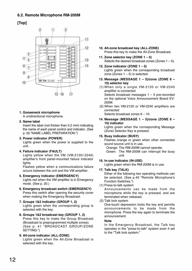
1. Gooseneck microphone A unidirectional microphone.
2. Name label Insert the label (not thicker than 0.2 mm) indicatingthe name of each panel control and indicator. (Seep. 50 "NAME LABEL PREPARATION.")
3. Power indicator (POWER) Lights green when the power is supplied to theunit.
4. Failure indicator (FAULT) Lights yellow when the VM (VM-2120/-2240)amplifier's front panel-mounted failure indicatorlights. Flashes yellow when a communications failureoccurs between the unit and the VM amplifier.
5. Emergency indicator (EMERGENCY) Lights red when the VM amplifier is in Emergencymode. (See p. 20.)
6. Emergency broadcast switch (EMERGENCY) Press this switch after opening the security coverwhen making the Emergency Broadcast.
7. Groups 1&2 indicator (GROUP 1, 2) Lights green when the corresponding group isselected with the key.
8. Groups 1&2 broadcast key (GROUP 1, 2) Press this key to make the Group Broadcast(Broadcast to preprogrammed multiple zones). (See p. 41 "BROADCAST GROUP/ZONESETTING.")
9. All-zone indicator (ALL-ZONE) Lights green when the All-Zone Broadcast isselected with the key.
10. All-zone broadcast key (ALL-ZONE) Press this key to make the All-Zone Broadcast.
11. Zone selector key (ZONE 1 – 5) Selects the desired broadcast zones (Zones 1 – 5).
12. Zone indicator (ZONE 1 – 5) Lights green when the corresponding broadcastzone (Zones 1 – 5) is selected.
13. Message (MESSAGE 1 – 5)/zone (ZONE 6 –10) selector key
(1) When only a single VM-2120 or VM-2240amplifier is connected Selects broadcast messages 1 – 5 pre-recordedon the optional Voice Announcement Board EV-200M.
(2) When two VM-2120 or VM-2240 amplifiers areconnected Selects broadcast zones 6 – 10.
14. Message (MESSAGE 1 – 5)/zone (ZONE 6 –10) indicator Lights green when the corresponding Message(Zone) Selector Key is pressed.
15. Busy indicator (BUSY) Flashes orange or green when other connectedsound source unit is in use.
Orange: The RM-200M cannot operate. Green: The RM-200M can interrupt the busy
unit.
16. In-use indicator (IN-USE) Lights green when the RM-200M is in use.
17. Talk key (TALK) Either of the following two operating methods canbe selected. (See p.40 "Remote Microphone'sFunction Switches.")
(1) Press-to-talk system Announcements can be made from themicrophone while the key is pressed, and areterminated when released.
(2) Talk lock systemOne-touch depression locks the key and permitsannouncements to be made from themicrophone. Press the key again to terminate theannouncement.
Note In the Emergency Broadcast, the Talk keyoperates in the "press-to-talk" system even if setto the "Talk lock system."
12 2
3
8
67
4 5
10
13
14
12
11
1615 17
9
13
2118 2019
1
2223
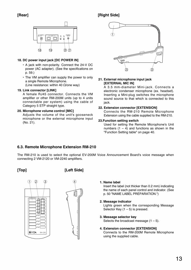
[Rear] [Right Side]
18. DC power input jack [DC POWER IN] • A jack with non-polarity. Connect the 24-V DC
power (AC adapter). (See the specifications onp. 59.)
• The VM amplifier can supply the power to onlya single Remote Microphone. (Line resistance: within 40 Ω/one way)
19. Link connector [LINK] A female RJ45 connector. Connects the VMamplifier or other RM-200M units (up to 4 unitsconnectable per system) using the cable ofCategory 5 STP straight type.
20. Microphone volume control [MIC] Adjusts the volume of the unit's gooseneckmicrophone or the external microphone input(No. 21).
21. External microphone input jack [EXTERNAL MIC IN] A 3.5 mm-diameter Mini-jack. Connects aelectronic condenser microphone (ex. headset).Inserting a Mini-plug switches the microphonesound source to that which is connected to thisjack.
22. Extension connector [EXTENSION] Connects the RM-210 Remote MicrophoneExtension using the cable supplied to the RM-210.
23.Function setting switch Used for setting the Remote Microphone's Unitnumbers (1 – 4) and functions as shown in the"Function Setting table" on page 40.
6.3. Remote Microphone Extension RM-210
The RM-210 is used to select the optional EV-200M Voice Announcement Board's voice message whenconnecting 2 VM-2120 or VM-2240 amplifiers.
[Top] [Left Side]
1 32 4 1. Name label Insert the label (not thicker than 0.2 mm) indicatingthe name of each panel control and indicator. (Seep. 50 "NAME LABEL PREPARATION.")
2. Message indicator Lights green when the corresponding MessageSelector Key (1 – 5) is pressed.
3. Message selector key Selects the broadcast message (1 – 5).
4. Extension connector [EXTENSION] Connects to the RM-200M Remote Microphoneusing the supplied cable.
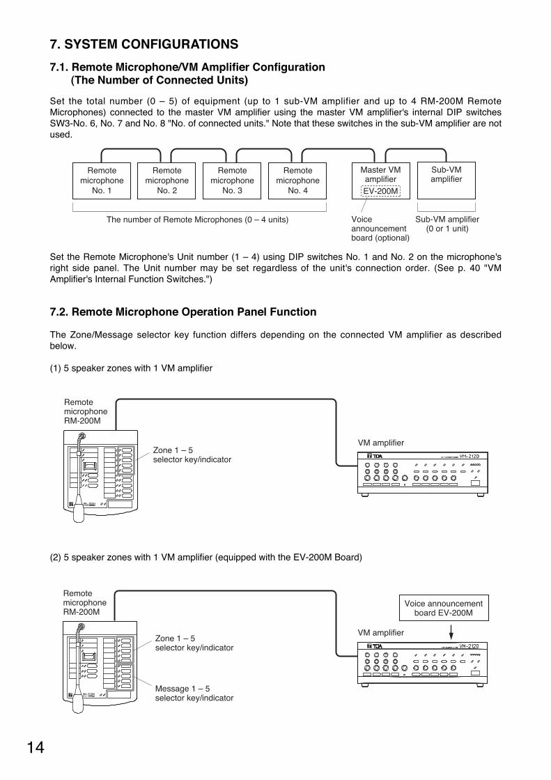
7. SYSTEM CONFIGURATIONS
7.1. Remote Microphone/VM Amplifier Configuration (The Number of Connected Units)
Set the total number (0 – 5) of equipment (up to 1 sub-VM amplifier and up to 4 RM-200M RemoteMicrophones) connected to the master VM amplifier using the master VM amplifier's internal DIP switchesSW3-No. 6, No. 7 and No. 8 "No. of connected units." Note that these switches in the sub-VM amplifier are notused.
Set the Remote Microphone's Unit number (1 – 4) using DIP switches No. 1 and No. 2 on the microphone'sright side panel. The Unit number may be set regardless of the unit's connection order. (See p. 40 "VMAmplifier's Internal Function Switches.")
7.2. Remote Microphone Operation Panel Function
The Zone/Message selector key function differs depending on the connected VM amplifier as describedbelow.
(1) 5 speaker zones with 1 VM amplifier
(2) 5 speaker zones with 1 VM amplifier (equipped with the EV-200M Board)
14
Message 1 – 5 selector key/indicator
RemotemicrophoneRM-200M
VM amplifierZone 1 – 5 selector key/indicator
Voice announcementboard EV-200M
Remotemicrophone
No. 2
Remotemicrophone
No. 1
Remotemicrophone
No. 3
Remotemicrophone
No. 4
Master VMamplifierEV-200M
Sub-VMamplifier
Sub-VM amplifier(0 or 1 unit)
The number of Remote Microphones (0 – 4 units) Voiceannouncementboard (optional)
RemotemicrophoneRM-200M
VM amplifierZone 1 – 5 selector key/indicator
15
Zone 6 – 10 selector key/indicator
RemotemicrophoneRM-200M
Master VM amplifier
Sub-VM amplifier
Zone 1 – 5 selector key/indicatorZone 1 – 10 selector key/indicator
Zone 1 – 10 selector key/indicator
Zone 6 – 10 selector key/indicator
Message 1 – 5 selector key/indicator
RemotemicrophoneRM-200M
Remote microphone extentionRM-210
Master VM amplifier
Sub-VM amplifier
Zone 1 – 5 selector key/indicator
Voice announcementboard EV-200M
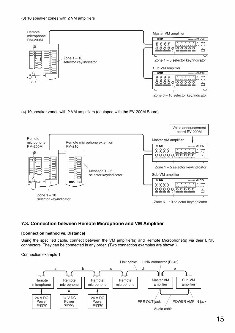
(3) 10 speaker zones with 2 VM amplifiers
(4) 10 speaker zones with 2 VM amplifiers (equipped with the EV-200M Board)
7.3. Connection between Remote Microphone and VM Amplifier
[Connection method vs. Distance]
Using the specified cable, connect between the VM amplifier(s) and Remote Microphone(s) via their LINKconnectors. They can be connected in any order. (Two connection examples are shown.)
Connection example 1
Remotemicrophone
Remotemicrophone
24 V DCPowersupply
24 V DCPowersupply
24 V DCPowersupply
Remotemicrophone
Remotemicrophone
Master VMamplifier
Sub-VMamplifier
a b c d e
LINK connector (RJ45)Link cable*
PRE OUT jack POWER AMP IN jack
Audio cable
16
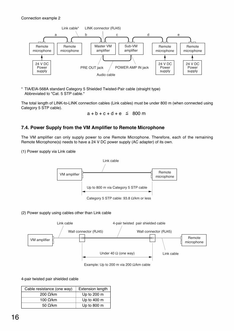
Extension length Up to 200 m Up to 400 m Up to 800 m
Cable resistance (one way) 200 Ω/km100 Ω/km50 Ω/km
Connection example 2
* TIA/EIA-568A standard Category 5 Shielded Twisted-Pair cable (straight type) Abbreviated to "Cat. 5 STP cable."
The total length of LINK-to-LINK connection cables (Link cables) must be under 800 m (when connected usingCategory 5 STP cable).
a + b + c + d + e 800 m
7.4. Power Supply from the VM Amplifier to Remote Microphone
The VM amplifier can only supply power to one Remote Microphone. Therefore, each of the remainingRemote Microphone(s) needs to have a 24 V DC power supply (AC adapter) of its own.
(1) Power supply via Link cable
(2) Power supply using cables other than Link cable
4-pair twisted pair shielded cable
Remotemicrophone
Remotemicrophone
24 V DCPowersupply
24 V DCPowersupply
24 V DCPowersupply
Remotemicrophone
Remotemicrophone
Master VMamplifier
Sub-VMamplifier
a b c d e
LINK connector (RJ45)Link cable*
PRE OUT jack POWER AMP IN jack
Audio cable
Remotemicrophone
Link cable
Link cable
4-pair twisted pair shielded cable
Under 40 Ω (one way)
VM amplifier
Example: Up to 200 m via 200 Ω/km cable
Wall connector (RJ45) Wall connector (RJ45)
Remotemicrophone
Link cable
Category 5 STP cable: 93.8 Ω/km or less
Up to 800 m via Category 5 STP cable
VM amplifier
17
8. EMERGENCY ("ALERT" AND "EVACUATION") BROADCAST
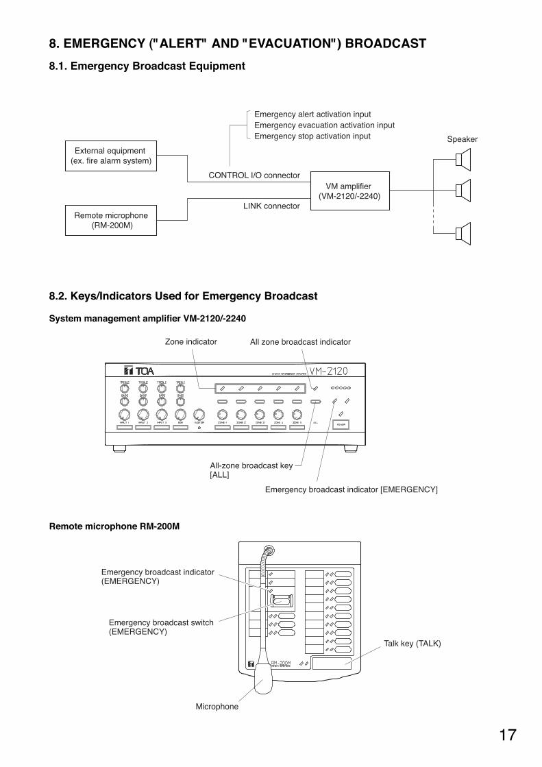
8.1. Emergency Broadcast Equipment
Emergency alert activation inputEmergency evacuation activation inputEmergency stop activation input
External equipment (ex. fire alarm system)
VM amplifier (VM-2120/-2240)
Remote microphone (RM-200M)
Speaker
CONTROL I/O connector
LINK connector
8.2. Keys/Indicators Used for Emergency Broadcast
System management amplifier VM-2120/-2240
Remote microphone RM-200M
Zone indicator All zone broadcast indicator
All-zone broadcast key [ALL]
Emergency broadcast indicator [EMERGENCY]
Emergency broadcast indicator(EMERGENCY)
Emergency broadcast switch (EMERGENCY)
Talk key (TALK)
Microphone
18
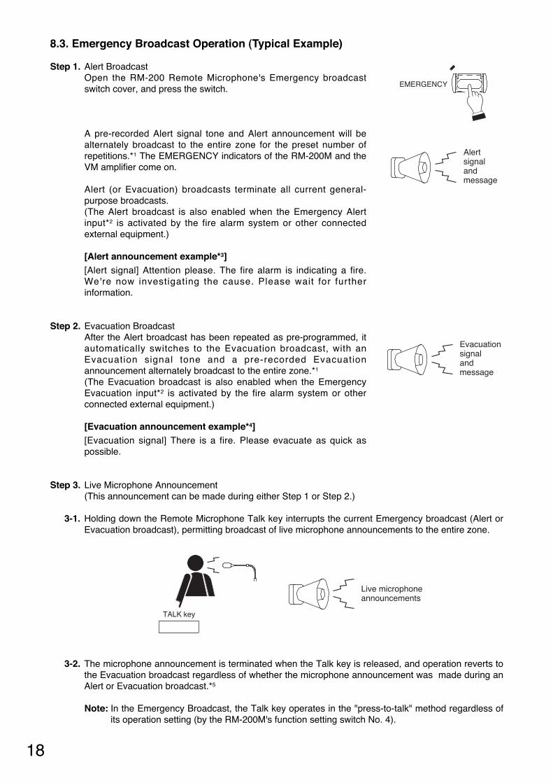
8.3. Emergency Broadcast Operation (Typical Example)
Step 1. Alert Broadcast Open the RM-200 Remote Microphone's Emergency broadcastswitch cover, and press the switch.
A pre-recorded Alert signal tone and Alert announcement will bealternately broadcast to the entire zone for the preset number ofrepetitions.*1 The EMERGENCY indicators of the RM-200M and theVM amplifier come on.
Alert (or Evacuation) broadcasts terminate all current general-purpose broadcasts. (The Alert broadcast is also enabled when the Emergency Alertinput*2 is activated by the fire alarm system or other connectedexternal equipment.)
[Alert announcement example*3] [Alert signal] Attention please. The fire alarm is indicating a fire.We're now investigating the cause. Please wait for furtherinformation.
Step 2. Evacuation Broadcast After the Alert broadcast has been repeated as pre-programmed, itautomatically switches to the Evacuation broadcast, with anEvacuation signal tone and a pre-recorded Evacuationannouncement alternately broadcast to the entire zone.*1
(The Evacuation broadcast is also enabled when the EmergencyEvacuation input*2 is activated by the fire alarm system or otherconnected external equipment.)
[Evacuation announcement example*4] [Evacuation signal] There is a fire. Please evacuate as quick aspossible.
Step 3. Live Microphone Announcement (This announcement can be made during either Step 1 or Step 2.)
3-1. Holding down the Remote Microphone Talk key interrupts the current Emergency broadcast (Alert orEvacuation broadcast), permitting broadcast of live microphone announcements to the entire zone.
3-2. The microphone announcement is terminated when the Talk key is released, and operation reverts tothe Evacuation broadcast regardless of whether the microphone announcement was made during anAlert or Evacuation broadcast.*5
Note: In the Emergency Broadcast, the Talk key operates in the "press-to-talk" method regardless ofits operation setting (by the RM-200M's function setting switch No. 4).
EMERGENCY
Alertsignalandmessage
Evacuationsignalandmessage
TALK key
Live microphone announcements
19
Step 4. Emergency Broadcast TerminationTo terminate the Emergency broadcast, activate the Emergency Stop input by way of thecorresponding connected external equipment. The unit returns to the general-purpose broadcastmode it was in immediately before the Emergency broadcast was started. Then, both EMERGENCYindicators of the RM-200M and the VM amplifier go out.
Note, however, that the unit does not return to the original general-purpose broadcast depending onthe type of general-purpose broadcast. (See p. 20.)
Notes • Emergency broadcasts are always made at the maximum volume level. The master and zone volume
controls cannot be used during Emergency broadcast.
• Emergency broadcast cannot be terminated by the Remote Microphone.
• If emergency broadcast is stopped using the Reset key, the unit could not return to the mode it was last inbefore the emergency broadcast was activated.
• When the unit not equipped with the EV-200M is placed in emergency broadcast mode, announcementsfrom the Remote Microphone can be broadcast over the entire area (by bypassing the attenuator). Press theRemote Microphone's talk switch to make the announcement.
*1 Requires installation of the optional EV-200M Voice Announcement Board.
*2 A terminal built in the rear-mounted CONTROL I/O connector
*3 Requires recording of the Alert signal, broadcast message, and their number of repetitions on an installedCompactFlash (CF) card. (Consult the dealer from whom the unit was purchased.)
*4 Requires recording of the Evacuation signal and broadcast message on an installed CompactFlash (CF)card. (Consult the dealer from whom the unit was purchased.)
*5 The unit is placed in this operation mode when the internal function switch (SW3-3) is set to the factory-preset position. This switch can be used to switch the microphone to "silent" mode after announcementcompletion. (See p. 40 "VM Amplifier's Internal Function Switches.") Note that this setting places the system in silent mode following a live microphone announcement, allowingfurther announcements to be made. Therefore, continuously repeat emergency announcements using themicrophone to evacuate building occupants to safe locations.
20
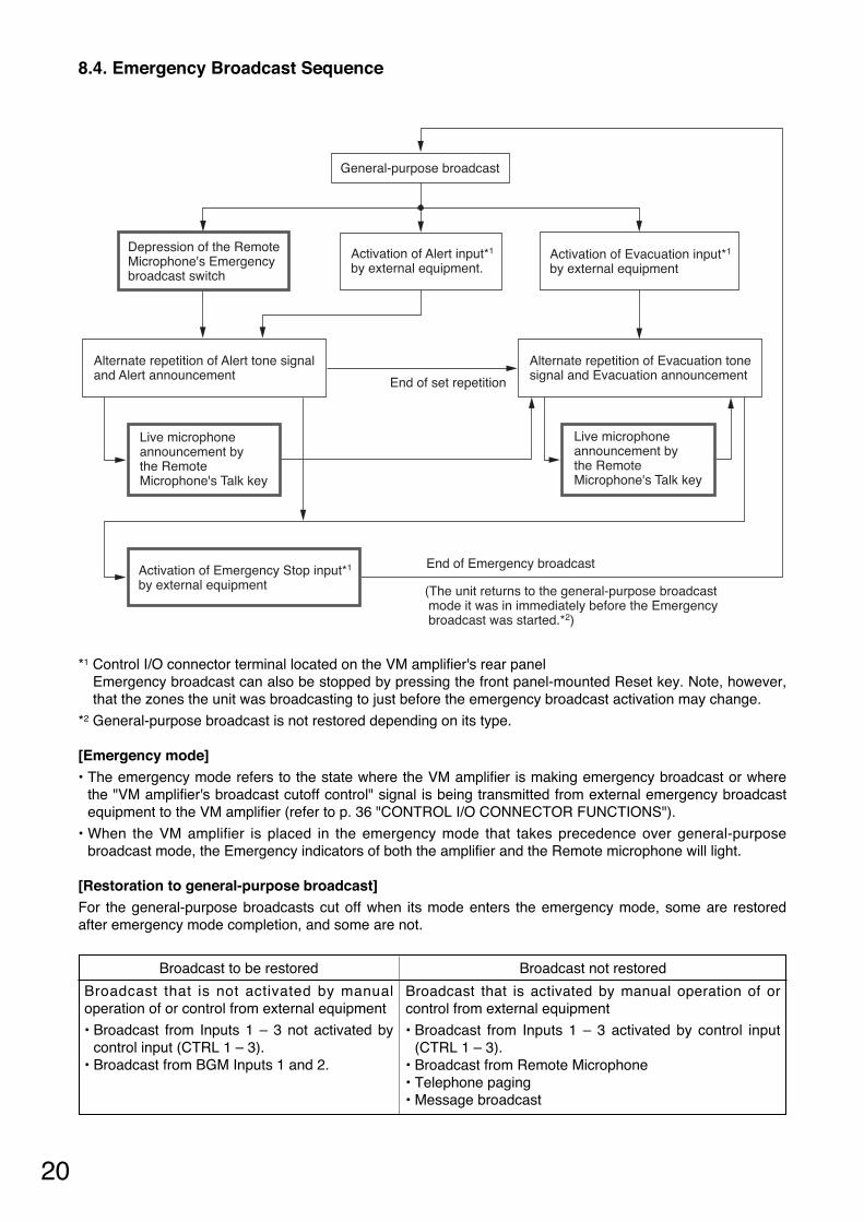
8.4. Emergency Broadcast Sequence
General-purpose broadcast
Depression of the Remote Microphone's Emergency broadcast switch
Activation of Alert input*1 by external equipment.
Activation of Evacuation input*1 by external equipment
Alternate repetition of Alert tone signal and Alert announcement
Alternate repetition of Evacuation tone signal and Evacuation announcementEnd of set repetition
Activation of Emergency Stop input*1
by external equipment
End of Emergency broadcast
(The unit returns to the general-purpose broadcast mode it was in immediately before the Emergency broadcast was started.*2)
Live microphone announcement by the Remote Microphone's Talk key
Live microphone announcement by the Remote Microphone's Talk key
*1 Control I/O connector terminal located on the VM amplifier's rear panel Emergency broadcast can also be stopped by pressing the front panel-mounted Reset key. Note, however,that the zones the unit was broadcasting to just before the emergency broadcast activation may change.
*2 General-purpose broadcast is not restored depending on its type.
[Emergency mode] • The emergency mode refers to the state where the VM amplifier is making emergency broadcast or where
the "VM amplifier's broadcast cutoff control" signal is being transmitted from external emergency broadcastequipment to the VM amplifier (refer to p. 36 "CONTROL I/O CONNECTOR FUNCTIONS").
• When the VM amplifier is placed in the emergency mode that takes precedence over general-purposebroadcast mode, the Emergency indicators of both the amplifier and the Remote microphone will light.
[Restoration to general-purpose broadcast] For the general-purpose broadcasts cut off when its mode enters the emergency mode, some are restoredafter emergency mode completion, and some are not.
Broadcast to be restored Broadcast not restored
Broadcast that is not activated by manualoperation of or control from external equipment
• Broadcast from Inputs 1 – 3 not activated bycontrol input (CTRL 1 – 3).
• Broadcast from BGM Inputs 1 and 2.
Broadcast that is activated by manual operation of orcontrol from external equipment
• Broadcast from Inputs 1 – 3 activated by control input(CTRL 1 – 3).
• Broadcast from Remote Microphone • Telephone paging • Message broadcast
21
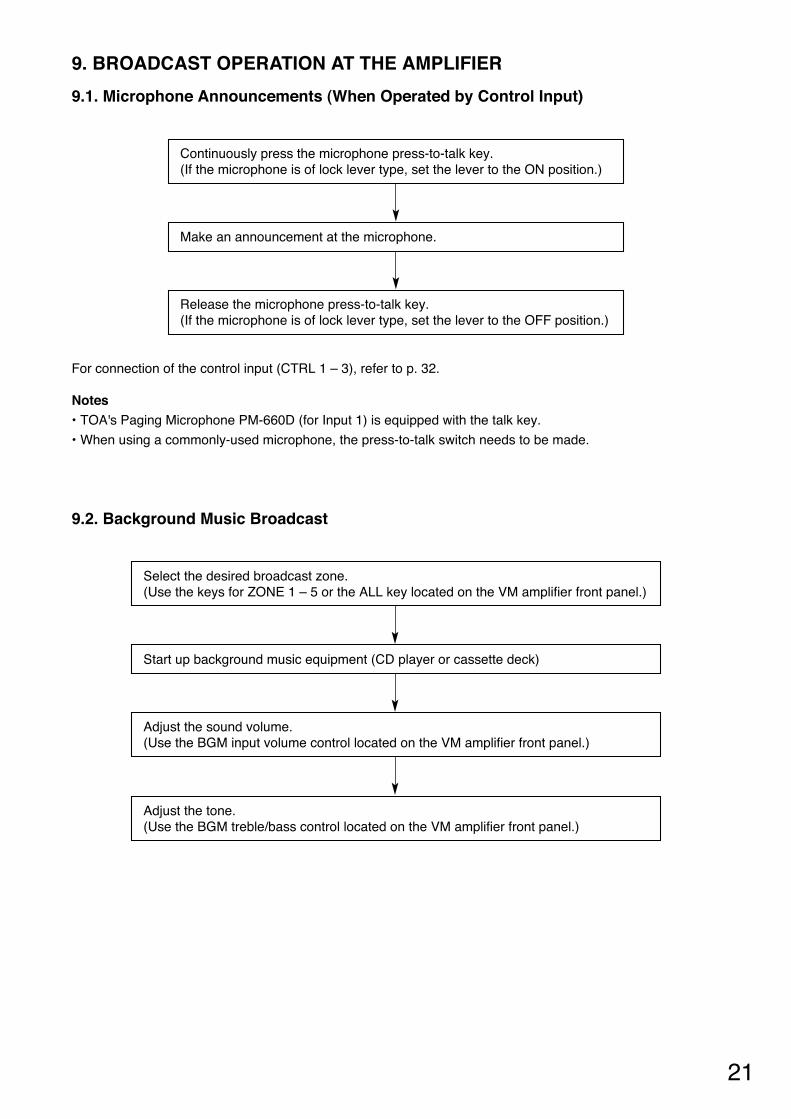
9. BROADCAST OPERATION AT THE AMPLIFIER
9.1. Microphone Announcements (When Operated by Control Input)
For connection of the control input (CTRL 1 – 3), refer to p. 32.
Notes • TOA's Paging Microphone PM-660D (for Input 1) is equipped with the talk key.
• When using a commonly-used microphone, the press-to-talk switch needs to be made.
9.2. Background Music Broadcast
Adjust the sound volume. (Use the BGM input volume control located on the VM amplifier front panel.)
Make an announcement at the microphone.
Continuously press the microphone press-to-talk key. (If the microphone is of lock lever type, set the lever to the ON position.)
Release the microphone press-to-talk key. (If the microphone is of lock lever type, set the lever to the OFF position.)
Start up background music equipment (CD player or cassette deck)
Select the desired broadcast zone. (Use the keys for ZONE 1 – 5 or the ALL key located on the VM amplifier front panel.)
Adjust the tone. (Use the BGM treble/bass control located on the VM amplifier front panel.)

22
10. REMOTE MICROPHONE GENERAL-PURPOSE BROADCAST
10.1. Operation and Display Sections
The panel functions of the operation and display sections differ depending on the amplifier configuration (5zones or 10 zones) and the use of the Recorded Message Announcement function. The figure shows anexample of the operation panel function for a 5-zone single amplifier configuration with the VoiceAnnouncement Board. (For samples of the operation panel functions for other amplifier configuration, see p.14 "Remote Microphone Operation Panel Function.")
Notes • Both the Busy indicator and the In-use indicator indicate the ready status for live microphone
announcements made after selecting the broadcast zone(s) with the All-zone, Zone, or Group selector key.Their indications have nothing to do with the Recorded message broadcast.
• For priority levels of Remote Microphone live announcements and Recorded messages, see p. 26"GENERAL-PURPOSE BROADCAST PRIORITY."
[Broadcast volume]
All announcements (including Recorded messages) from the Remote Microphone are broadcast at themaximum volume level regardless of the settings of the master volume control and zone volume control. Also,the amplifier performs relay control to permit the announcements to bypass external speaker attenuators.
Zone selector key (ZONE 1 – 5)
Zone indicator
Talk key (TALK)
Message selector key (MESSAGE 1 – 5)
Message indicator
Busy indicator (BUSY)Flashes orange or green when other connected sound source unit is in use. Orange: The RM-200M cannot operate. Green: The RM-200M can interrupt the busy unit.
In-use indicator (IN-USE)Lights green when the RM-200M is in use.
Microphone
Power indicator (POWER)
Failure indicator (FAULT)
Group 1&2 broadcast key(GROUP 1, 2)
Group 1&2 indicator
All-zone broadcast key(ALL-ZONE)
All-zone indicator
Remote microphone RM-200M
23
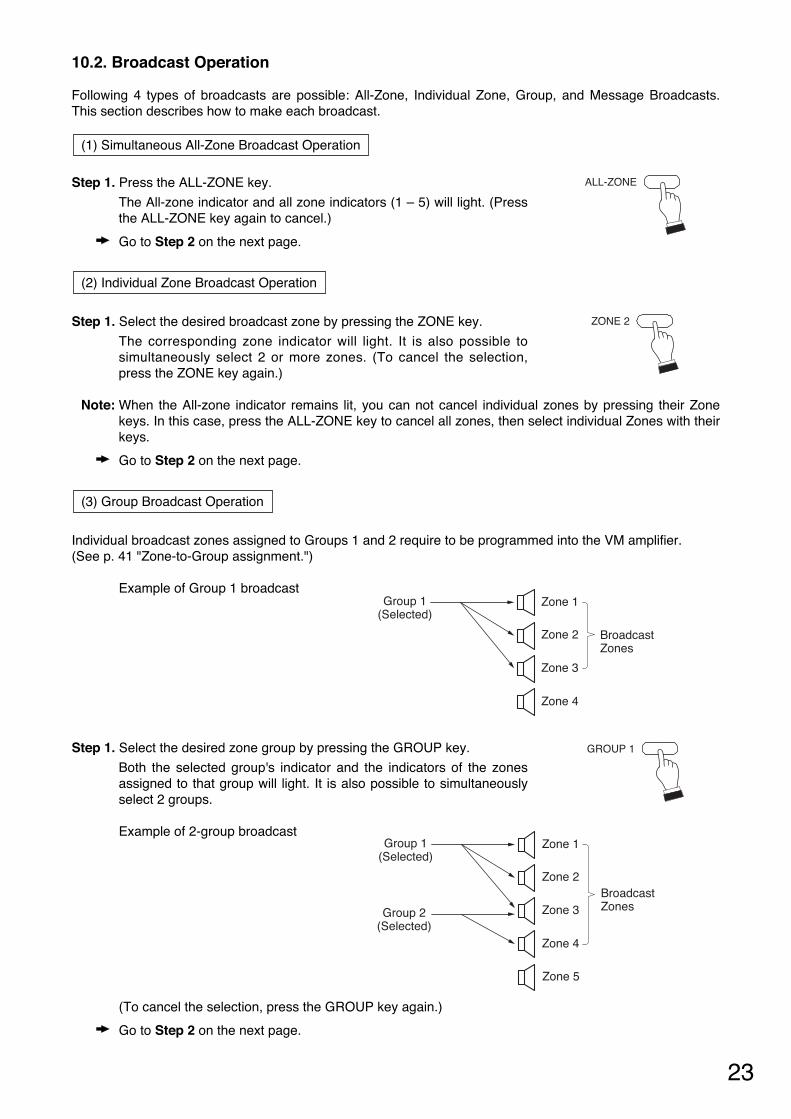
10.2. Broadcast Operation
Following 4 types of broadcasts are possible: All-Zone, Individual Zone, Group, and Message Broadcasts.This section describes how to make each broadcast.
Step 1. Press the ALL-ZONE key.
The All-zone indicator and all zone indicators (1 – 5) will light. (Pressthe ALL-ZONE key again to cancel.)
Go to Step 2 on the next page.
Step 1. Select the desired broadcast zone by pressing the ZONE key.
The corresponding zone indicator will light. It is also possible tosimultaneously select 2 or more zones. (To cancel the selection,press the ZONE key again.)
Note: When the All-zone indicator remains lit, you can not cancel individual zones by pressing their Zonekeys. In this case, press the ALL-ZONE key to cancel all zones, then select individual Zones with theirkeys.
Go to Step 2 on the next page.
Individual broadcast zones assigned to Groups 1 and 2 require to be programmed into the VM amplifier. (See p. 41 "Zone-to-Group assignment.")
Example of Group 1 broadcast
Step 1. Select the desired zone group by pressing the GROUP key.
Both the selected group's indicator and the indicators of the zonesassigned to that group will light. It is also possible to simultaneouslyselect 2 groups.
Example of 2-group broadcast
(To cancel the selection, press the GROUP key again.)
Go to Step 2 on the next page.
(3) Group Broadcast Operation
(2) Individual Zone Broadcast Operation
(1) Simultaneous All-Zone Broadcast Operation
ALL-ZONE
ZONE 2
GROUP 1
Zone 1Group 1(Selected)
Zone 2
Zone 3
Zone 4
BroadcastZones
Zone 1Group 1(Selected)
Group 2(Selected)
Zone 2
Zone 3
Zone 4
Zone 5
BroadcastZones
24
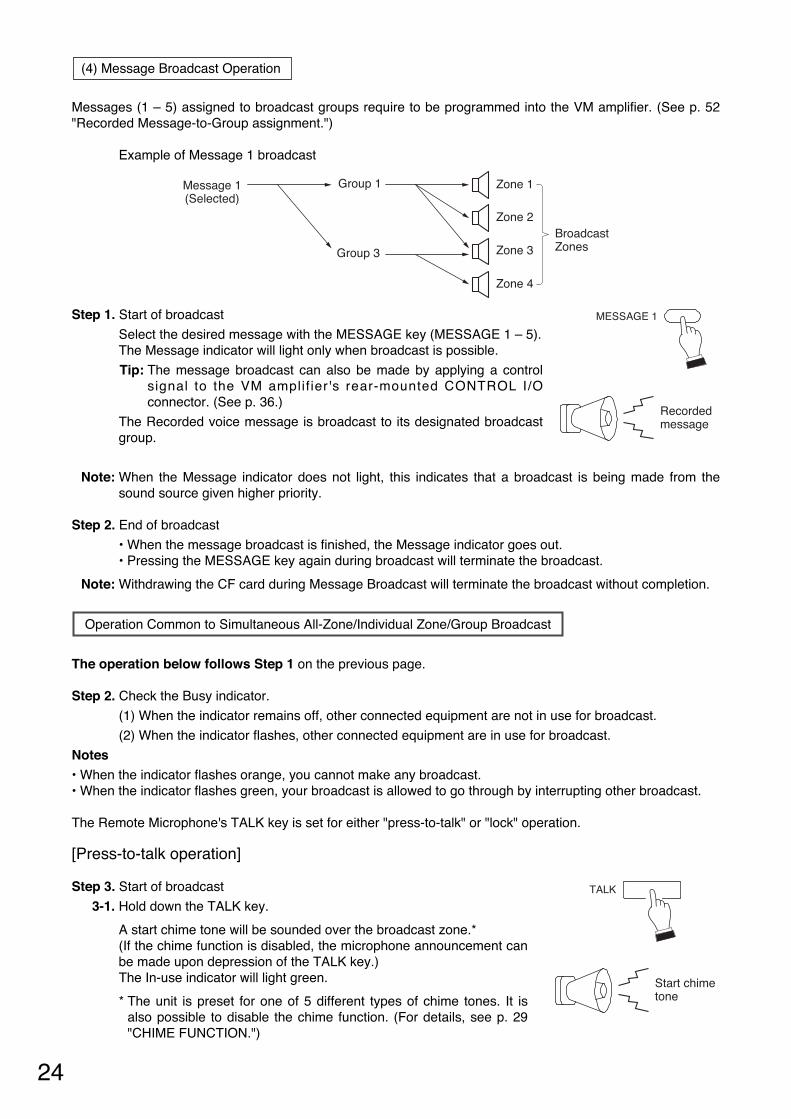
Messages (1 – 5) assigned to broadcast groups require to be programmed into the VM amplifier. (See p. 52"Recorded Message-to-Group assignment.")
Example of Message 1 broadcast
Step 1. Start of broadcast
Select the desired message with the MESSAGE key (MESSAGE 1 – 5).The Message indicator will light only when broadcast is possible.
Tip: The message broadcast can also be made by applying a controlsignal to the VM amplif ier's rear-mounted CONTROL I/Oconnector. (See p. 36.)
The Recorded voice message is broadcast to its designated broadcastgroup.
Note: When the Message indicator does not light, this indicates that a broadcast is being made from thesound source given higher priority.
Step 2. End of broadcast
• When the message broadcast is finished, the Message indicator goes out. • Pressing the MESSAGE key again during broadcast will terminate the broadcast.
Note: Withdrawing the CF card during Message Broadcast will terminate the broadcast without completion.
The operation below follows Step 1 on the previous page.
Step 2. Check the Busy indicator.
(1) When the indicator remains off, other connected equipment are not in use for broadcast.
(2) When the indicator flashes, other connected equipment are in use for broadcast.
Notes • When the indicator flashes orange, you cannot make any broadcast. • When the indicator flashes green, your broadcast is allowed to go through by interrupting other broadcast.
The Remote Microphone's TALK key is set for either "press-to-talk" or "lock" operation.
[Press-to-talk operation]
Step 3. Start of broadcast
3-1. Hold down the TALK key.
A start chime tone will be sounded over the broadcast zone.* (If the chime function is disabled, the microphone announcement canbe made upon depression of the TALK key.) The In-use indicator will light green.
* The unit is preset for one of 5 different types of chime tones. It isalso possible to disable the chime function. (For details, see p. 29"CHIME FUNCTION.")
Operation Common to Simultaneous All-Zone/Individual Zone/Group Broadcast
(4) Message Broadcast Operation
MESSAGE 1
Recorded message
Message 1(Selected)
Zone 1Group 1
Group 3
Zone 2
Zone 3
Zone 4
BroadcastZones
TALK
Start chimetone
25
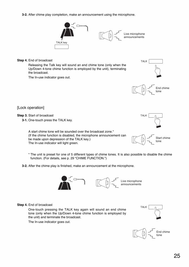
3-2. After chime play completion, make an announcement using the microphone.
Step 4. End of broadcast
Releasing the Talk key will sound an end chime tone (only when theUp/Down 4-tone chime function is employed by the unit), terminatingthe broadcast.
The In-use indicator goes out.
[Lock operation]
Step 3. Start of broadcast
3-1. One-touch press the TALK key.
A start chime tone will be sounded over the broadcast zone.* (If the chime function is disabled, the microphone announcement canbe made upon depression of the TALK key.)The In-use indicator will light green.
* The unit is preset for one of 5 different types of chime tones. It is also possible to disable the chimefunction. (For details, see p. 29 "CHIME FUNCTION.")
3-2. After the chime play is finished, make an announcement at the microphone.
Step 4. End of broadcast
One-touch pressing the TALK key again will sound an end chimetone (only when the Up/Down 4-tone chime function is employed bythe unit) and terminate the broadcast.
The In-use indicator goes out.
TALK
TALK
Start chimetone
End chime tone
Live microphone announcements
TALK
End chime tone
TALK key
Live microphone announcements
26
Functional explanation
Priority 1 or 2 selectable. Priority 3 is set when broadcast isnot externally activated.*2
Priority 1 or 2 selectable.
Set for Priority 1.
Priority 1 or 3 selectable.
For Alert message
For Evacuation message
Priority 3 is set when chime isexternally activated.*3
Set for Priority 4.
11. GENERAL-PURPOSE BROADCAST PRIORITY
11.1. Broadcast Source-to-Priority Relationship
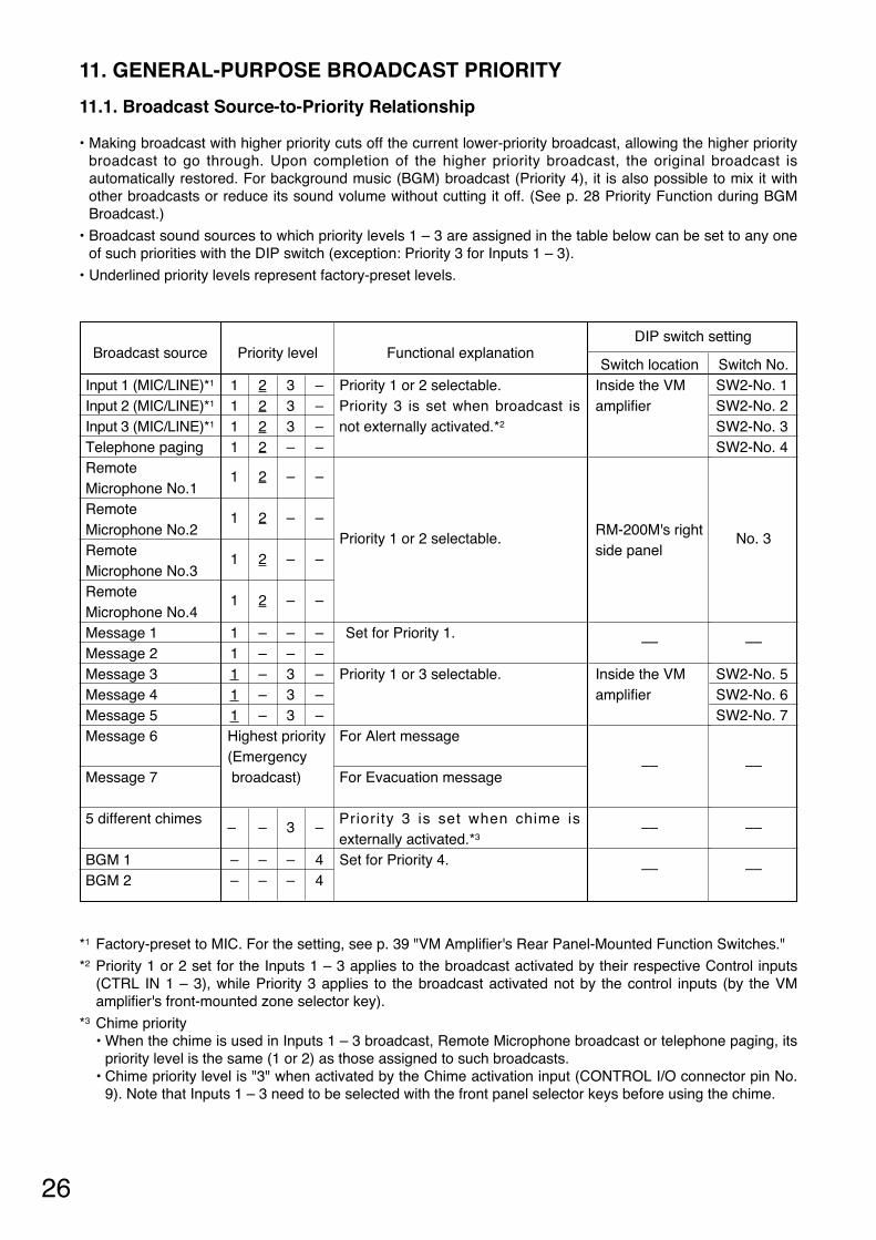
• Making broadcast with higher priority cuts off the current lower-priority broadcast, allowing the higher prioritybroadcast to go through. Upon completion of the higher priority broadcast, the original broadcast isautomatically restored. For background music (BGM) broadcast (Priority 4), it is also possible to mix it withother broadcasts or reduce its sound volume without cutting it off. (See p. 28 Priority Function during BGMBroadcast.)
• Broadcast sound sources to which priority levels 1 – 3 are assigned in the table below can be set to any oneof such priorities with the DIP switch (exception: Priority 3 for Inputs 1 – 3).
• Underlined priority levels represent factory-preset levels.
Broadcast source
Input 1 (MIC/LINE)*1
Input 2 (MIC/LINE)*1
Input 3 (MIC/LINE)*1
Telephone paging Remote Microphone No.1 Remote Microphone No.2 Remote Microphone No.3 Remote Microphone No.4 Message 1 Message 2 Message 3 Message 4 Message 5 Message 6
Message 7
5 different chimes
BGM 1 BGM 2
Priority level
1 2 3 – 1 2 3 – 1 2 3 – 1 2 – –
1 2 – –
1 2 – –
1 2 – –
1 2 – –
1 – – – 1 – – – 1 – 3 – 1 – 3 – 1 – 3 – Highest priority (Emergency broadcast)
– – 3 –
– – – 4 – – – 4
Switch location Inside the VM amplifier
RM-200M's right side panel
––
Inside the VM amplifier
––
––
––
Switch No. SW2-No. 1 SW2-No. 2 SW2-No. 3 SW2-No. 4
No. 3
––
SW2-No. 5 SW2-No. 6 SW2-No. 7
––
––
––
DIP switch setting
*1 Factory-preset to MIC. For the setting, see p. 39 "VM Amplifier's Rear Panel-Mounted Function Switches."
*2 Priority 1 or 2 set for the Inputs 1 – 3 applies to the broadcast activated by their respective Control inputs(CTRL IN 1 – 3), while Priority 3 applies to the broadcast activated not by the control inputs (by the VMamplifier's front-mounted zone selector key).
*3 Chime priority • When the chime is used in Inputs 1 – 3 broadcast, Remote Microphone broadcast or telephone paging, its
priority level is the same (1 or 2) as those assigned to such broadcasts. • Chime priority level is "3" when activated by the Chime activation input (CONTROL I/O connector pin No.
9). Note that Inputs 1 – 3 need to be selected with the front panel selector keys before using the chime.
27
11.2. Broadcast Priority between Equipment with the Equal Priority Level
11.2.1. Priority mode between equipment with the equal priority level
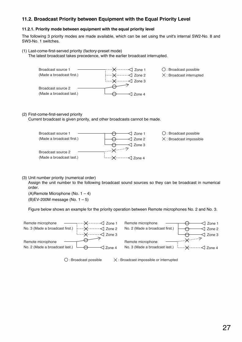
The following 3 priority modes are made available, which can be set using the unit's internal SW2-No. 8 andSW3-No. 1 switches.
(1) Last-come-first-served priority (factory-preset mode) The latest broadcast takes precedence, with the earlier broadcast interrupted.
(2) First-come-first-served priority Current broadcast is given priority, and other broadcasts cannot be made.
(3) Unit number priority (numerical order) Assign the unit number to the following broadcast sound sources so they can be broadcast in numericalorder.
(A)Remote Microphone (No. 1 – 4)
(B)EV-200M message (No. 1 – 5)
Figure below shows an example for the priority operation between Remote microphones No. 2 and No. 3.
Zone 1
Zone 2
Zone 3
Zone 4
: Broadcast possible
: Broadcast interrupted
Broadcast source 1(Made a broadcast first.)
Broadcast source 2(Made a broadcast last.)
Zone 1
Zone 2
Zone 3
Zone 4
: Broadcast possible
: Broadcast impossible
Broadcast source 1(Made a broadcast first.)
Broadcast source 2(Made a broadcast last.)
Zone 1
Zone 2
Zone 3
Zone 4
: Broadcast possible : Broadcast impossible or interrupted
Remote microphone No. 3 (Made a broadcast first.)
Remote microphone No. 2 (Made a broadcast last.)
Remote microphone No. 2 (Made a broadcast first.)
Remote microphone No. 3 (Made a broadcast last.)
Zone 1
Zone 2
Zone 3
Zone 4
28
Priority 2
––
––
BGM broadcast operation
Cut off. Cut off*1 or volume is decreased*2 *3.Volume is decreased*3. Mixed.
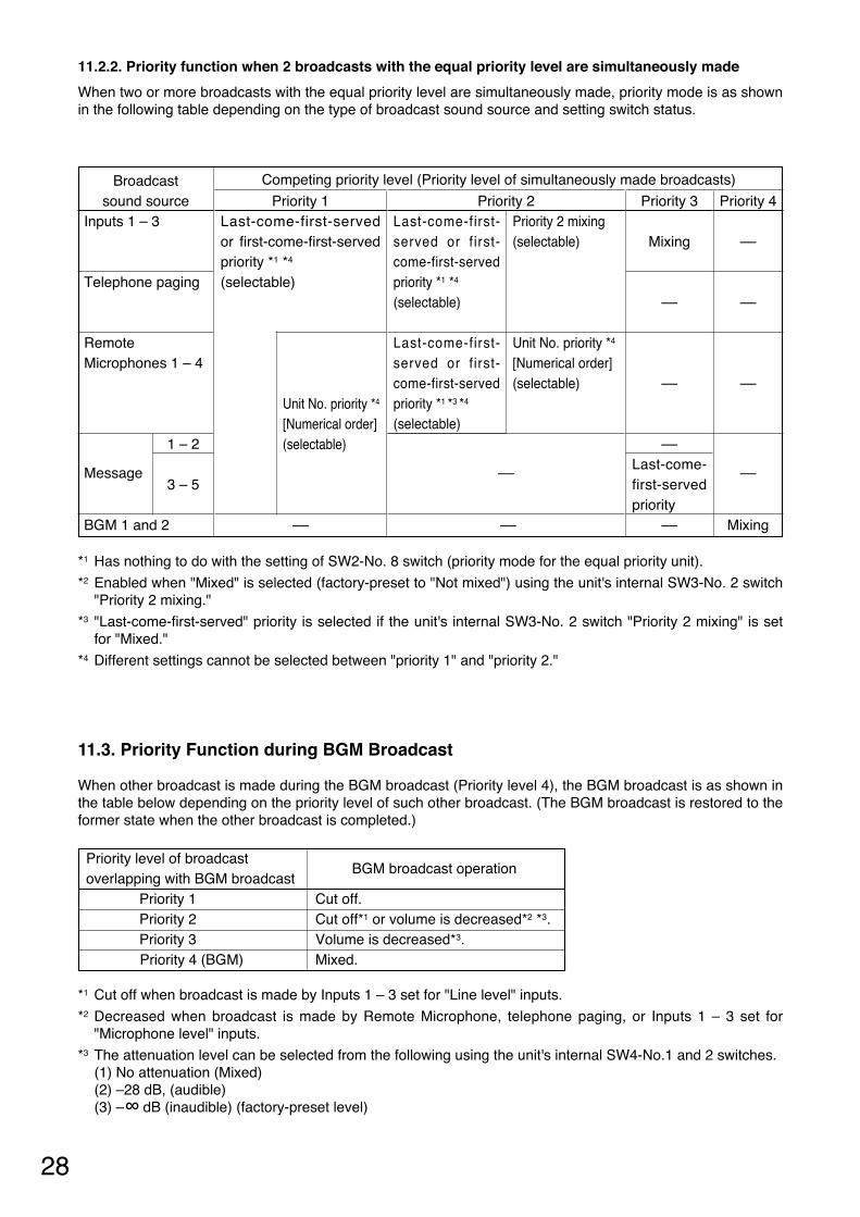
*1 Has nothing to do with the setting of SW2-No. 8 switch (priority mode for the equal priority unit).
*2 Enabled when "Mixed" is selected (factory-preset to "Not mixed") using the unit's internal SW3-No. 2 switch"Priority 2 mixing."
*3 "Last-come-first-served" priority is selected if the unit's internal SW3-No. 2 switch "Priority 2 mixing" is setfor "Mixed."
*4 Different settings cannot be selected between "priority 1" and "priority 2."
11.3. Priority Function during BGM Broadcast
When other broadcast is made during the BGM broadcast (Priority level 4), the BGM broadcast is as shown inthe table below depending on the priority level of such other broadcast. (The BGM broadcast is restored to theformer state when the other broadcast is completed.)
Priority level of broadcast overlapping with BGM broadcast
Priority 1 Priority 2 Priority 3 Priority 4 (BGM)
*1 Cut off when broadcast is made by Inputs 1 – 3 set for "Line level" inputs.
*2 Decreased when broadcast is made by Remote Microphone, telephone paging, or Inputs 1 – 3 set for"Microphone level" inputs.
*3 The attenuation level can be selected from the following using the unit's internal SW4-No.1 and 2 switches. (1) No attenuation (Mixed) (2) –28 dB, (audible) (3) –∞ dB (inaudible) (factory-preset level)
Priority 4
––
––
––
––
Mixing
11.2.2. Priority function when 2 broadcasts with the equal priority level are simultaneously made
When two or more broadcasts with the equal priority level are simultaneously made, priority mode is as shownin the following table depending on the type of broadcast sound source and setting switch status.
Broadcast sound source
Inputs 1 – 3
Telephone paging
Remote Microphones 1 – 4
Message
BGM 1 and 2
Priority 1 Last-come-first-servedor first-come-first-servedpriority *1 *4
(selectable)
––
Priority 3
Mixing
––
––
–– Last-come-first-servedpriority
––
Competing priority level (Priority level of simultaneously made broadcasts)
Last-come-first-served or f irst-come-first-servedpriority *1 *4
(selectable)
Last-come-first-served or f irst-come-first-servedpriority *1 *3 *4
(selectable)
Priority 2 mixing(selectable)
Unit No. priority *4
[Numerical order](selectable)
Unit No. priority *4
[Numerical order](selectable) 1 – 2
3 – 5
29
12. CHIME FUNCTION
12.1. Available Chime Tone Types
There are 5 different chimes (one of which can be selected for a pre-announcement chime).
12.1.1. Five different chime tones
• Four built-in chimes, and 1 pre-recorded chime that is made by recording any preferred sound source aremade available for selection. It is possible to disable the chime function.
• The type of chime can be selected with the unit's rear panel-mounted SETTINGS switches No. 3 – 5. It isfactory-preset to "2-tone chime". (See p. 39 "FUNCTION SWITCH OPERATION.")
Note: Different chime tones cannot be selected for different sound sources.
12.1.2. Four built-in chimes
This lineup consists of the following types.
• 2-tone chime • 4-tone chime (Up)*1
• Single-tone chime • 4-tone chime (Up & Down)*2
*1 An ascending 4-tone chime is sounded when the broadcast begins. *2 An ascending 4-tone chime is sounded when the broadcast begins, and descending 4-tone chime is
sounded upon broadcast completion.
12.1.3. Pre-recorded chime
The optional EV-200M Voice Announcement Board is required to use this function. A chime tone must be recorded on the Compact Flash (CF) card installed in the EV-200M. The recorded chime tone is assigned to the EV-200M's Message 8. (See p. 53 "COMPACTFLASH (CF)CARD RECORDING.")
12.2. How the Chime Tone Is Used
12.2.1. Chime tone for Inputs 1 – 3
• Either MIC (factory-preset) or LINE input signal level can be set for each input. Setting switch: SETTINGS switches No. 6 – 8 on the unit's rear panel.
• When the input is set for MIC level and the input source with Priority 1 or 2 is broadcast by remote control(CTRL IN 1, 2, 3*), a chime tone is automatically sounded when the broadcast is started (and completed).
• When input 1 or 2 is set for LINE level, a chime tone is not sounded when the corresponding source isbroadcast.
• When Input 3 is set for LINE level and the input source with Priority 1 or 2 is broadcast by remote control(CTRL IN 3*), a chime tone can be made to sound or not to sound when the broadcast is started (andcompleted). Setting switch: The unit's internal SW3-No. 4 switch "Input 3 (LINE) Chime ON/OFF"
(Factory-preset position: Chime OFF)
* The CTRL IN 1, 2, or 3 control input corresponds to the Input 1, 2, or 3, respectively.
12.2.2. Telephone paging chime tone
It is possible to select whether or not to sound a chime tone when the broadcast is started (and completed). Setting switch: SETTINGS switch No. 2 "Telephone Paging Chime ON/OFF" on the unit's rear panel.
(Factory-preset position: Chime OFF)
30
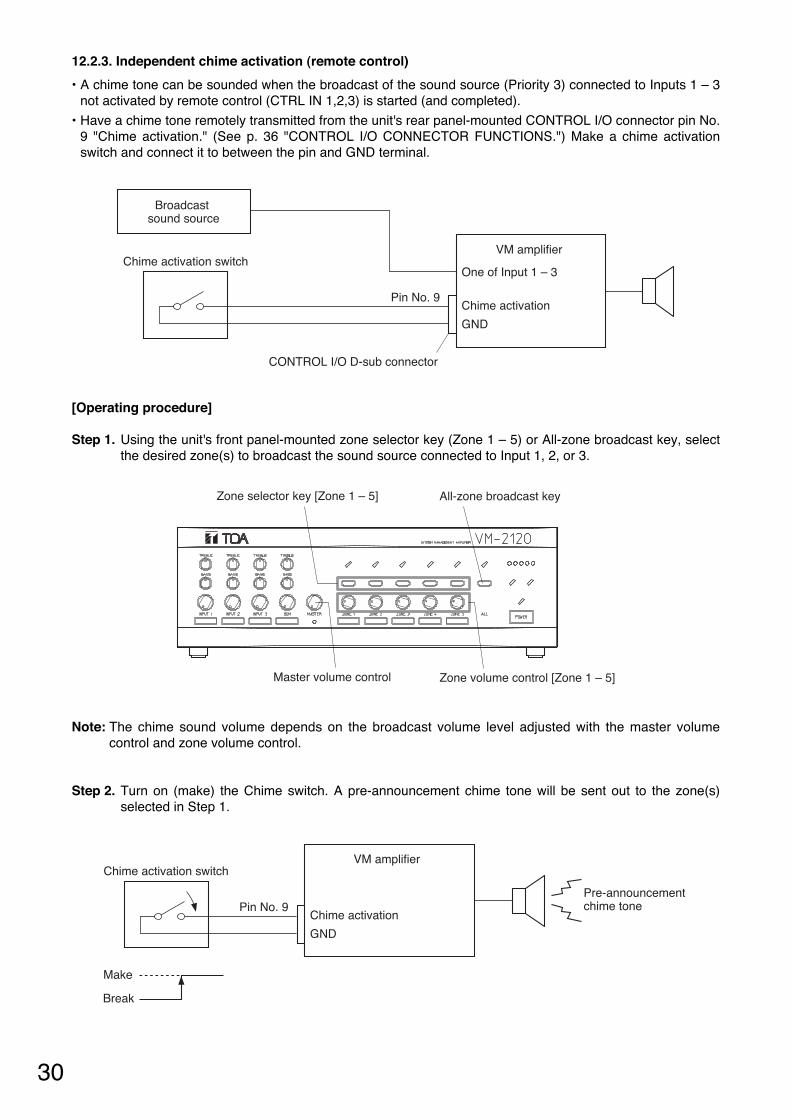
12.2.3. Independent chime activation (remote control)
• A chime tone can be sounded when the broadcast of the sound source (Priority 3) connected to Inputs 1 – 3not activated by remote control (CTRL IN 1,2,3) is started (and completed).
• Have a chime tone remotely transmitted from the unit's rear panel-mounted CONTROL I/O connector pin No.9 "Chime activation." (See p. 36 "CONTROL I/O CONNECTOR FUNCTIONS.") Make a chime activationswitch and connect it to between the pin and GND terminal.
[Operating procedure]
Step 1. Using the unit's front panel-mounted zone selector key (Zone 1 – 5) or All-zone broadcast key, selectthe desired zone(s) to broadcast the sound source connected to Input 1, 2, or 3.
Note: The chime sound volume depends on the broadcast volume level adjusted with the master volumecontrol and zone volume control.
Step 2. Turn on (make) the Chime switch. A pre-announcement chime tone will be sent out to the zone(s)selected in Step 1.
Broadcast sound source
VM amplifier
CONTROL I/O D-sub connector
One of Input 1 – 3
Chime activation
GND
Chime activation switch
Pin No. 9
VM amplifier
Chime activation
GND
Chime activation switch
Pin No. 9
Make
Break
Pre-announcement chime tone
Master volume control Zone volume control [Zone 1 – 5]
Zone selector key [Zone 1 – 5] All-zone broadcast key

31
13. CHOKE COIL INSTALLATION
The work must be done by a qualified service technician only. For the installation method, refer to the separate instruction manual for qualified service technicians.
14. INPUT TRANSFORMER INSTALLATION AND ITS BOARD MODIFICATION
The following work must be done by a qualified service technician only.
1. Input transformer installation 2. Modification to switch off the phantom power supply 3. Modification when the sub- and master VM amplifiers are connected
For the installation and modification methods, refer to the separate instruction manual for qualified servicetechnicians.
15. MOUNTING AN OPTIONAL EV-200M VOICE ANNOUNCEMENT BOARD
The work must be done by a qualified service technician only. For the mounting method, refer to the separate instruction manual for qualified service technicians.
16. MOUNTING AN OPTIONAL SV-200MA SURVEILLANCE BOARD
The work must be done by a qualified service technician only. For the mounting method, refer to the separate instruction manual for qualified service technicians.
Step 3. Turn off (break) the Chime switch when the broadcast is completed. A post-announcement chimetone will be sent out to the zone(s). (Only when the up & down 4-tone chime has been selected.)
Step 4. Press the selected zone selector key (Zone 1 – 5) again to terminate the broadcast.
VM amplifier
Chime activation
GND
Chime activation switch
Pin No. 9
Make
Break
Post-announcement chime tone
32
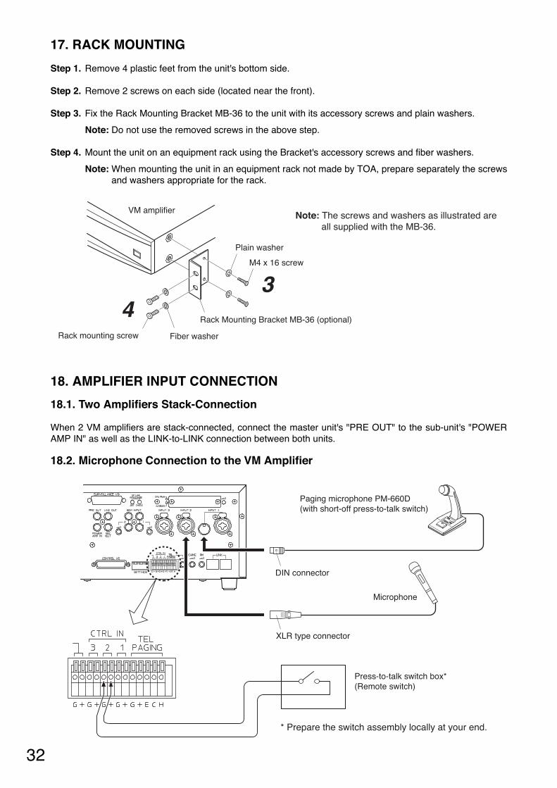
17. RACK MOUNTING
Step 1. Remove 4 plastic feet from the unit's bottom side.
Step 2. Remove 2 screws on each side (located near the front).
Step 3. Fix the Rack Mounting Bracket MB-36 to the unit with its accessory screws and plain washers.
Note: Do not use the removed screws in the above step.
Step 4. Mount the unit on an equipment rack using the Bracket's accessory screws and fiber washers.
Note: When mounting the unit in an equipment rack not made by TOA, prepare separately the screwsand washers appropriate for the rack.
18. AMPLIFIER INPUT CONNECTION
18.1. Two Amplifiers Stack-Connection
When 2 VM amplifiers are stack-connected, connect the master unit's "PRE OUT" to the sub-unit's "POWERAMP IN" as well as the LINK-to-LINK connection between both units.
18.2. Microphone Connection to the VM Amplifier
Note: The screws and washers as illustrated are all supplied with the MB-36.
Plain washer
Rack Mounting Bracket MB-36 (optional)
M4 x 16 screw
Fiber washerRack mounting screw
VM amplifier
34
* Prepare the switch assembly locally at your end.
XLR type connector
DIN connector
Paging microphone PM-660D(with short-off press-to-talk switch)
Microphone
Press-to-talk switch box*(Remote switch)
33
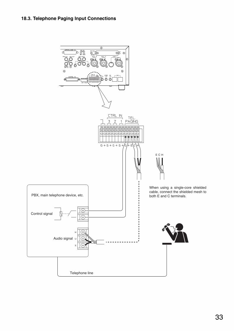
18.3. Telephone Paging Input Connections
EC
H
PBX, main telephone device, etc.
Control signal
Audio signal
E C H
When using a single-core shielded cable, connect the shielded mesh to both E and C terminals.
Telephone line

34
19. EXTERNAL ATTENUATOR CONTROL WIRING
19.1. 4-Wire System Connection
* This figure shows the relay operation status when the VM amplifier's power is switched off, when it is makingAll-zone or emergency broadcast or when its broadcast is cut off due to control from external equipment inemergency broadcast mode.
ATTENUATOR CONTROL relay contact capacity
Withstand voltage: 30 V DC, 125 V ACContact current: Under 7 A (DC), under 7 A (AC)
ATTENUATORCONTROL*
EXTERNAL SP INPUT
VM amplifier
DIRECT OUT
ZONE 1
ZONE 2
ZONE 3
ZONE 4
ZONE 5
N1 (NC)
N2 (NO)
H
C
C
H
H
C
+
–
H
C
H
C
H
C
H
C
H
C
Relay control
ZONE 1
External attenuators
External DC power supply to activate attenuators
H
C
Relay control
ZONE 2
H
C
Relay control
ZONE 3
H
C
Relay control
ZONE 4
H
C
Relay control
ZONE 5
35
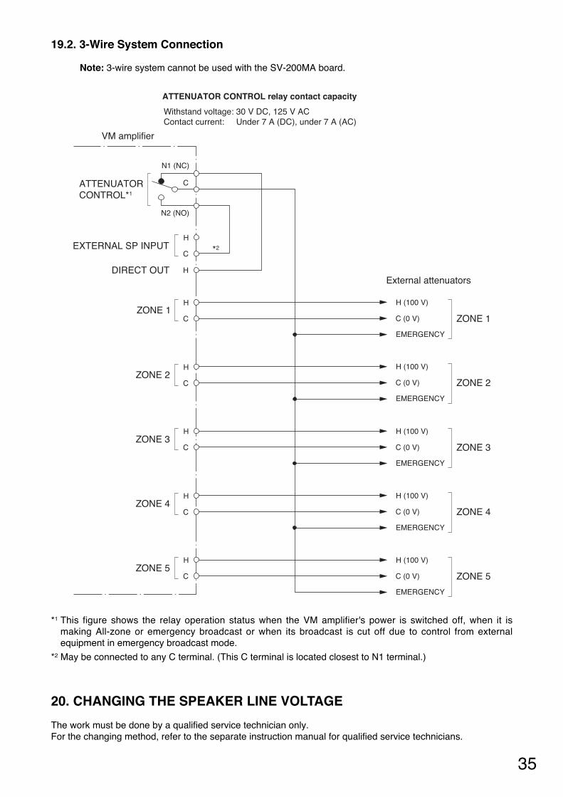
19.2. 3-Wire System Connection
Note: 3-wire system cannot be used with the SV-200MA board.
*1 This figure shows the relay operation status when the VM amplifier's power is switched off, when it ismaking All-zone or emergency broadcast or when its broadcast is cut off due to control from externalequipment in emergency broadcast mode.
*2 May be connected to any C terminal. (This C terminal is located closest to N1 terminal.)
20. CHANGING THE SPEAKER LINE VOLTAGE
The work must be done by a qualified service technician only. For the changing method, refer to the separate instruction manual for qualified service technicians.
ATTENUATOR CONTROL relay contact capacity
Withstand voltage: 30 V DC, 125 V ACContact current: Under 7 A (DC), under 7 A (AC)
ATTENUATORCONTROL*1
EXTERNAL SP INPUT
DIRECT OUT
ZONE 1
ZONE 2
ZONE 3
ZONE 4
ZONE 5
N1 (NC)
N2 (NO)
H
*2C
C
H
H
C
H
C
H
C
H
C
H
C
H (100 V)
C (0 V)
EMERGENCY
ZONE 1
H (100 V)
C (0 V)
EMERGENCY
ZONE 2
H (100 V)
C (0 V)
EMERGENCY
ZONE 3
H (100 V)
C (0 V)
EMERGENCY
ZONE 4
H (100 V)
C (0 V)
EMERGENCY
ZONE 5
VM amplifier
External attenuators
36
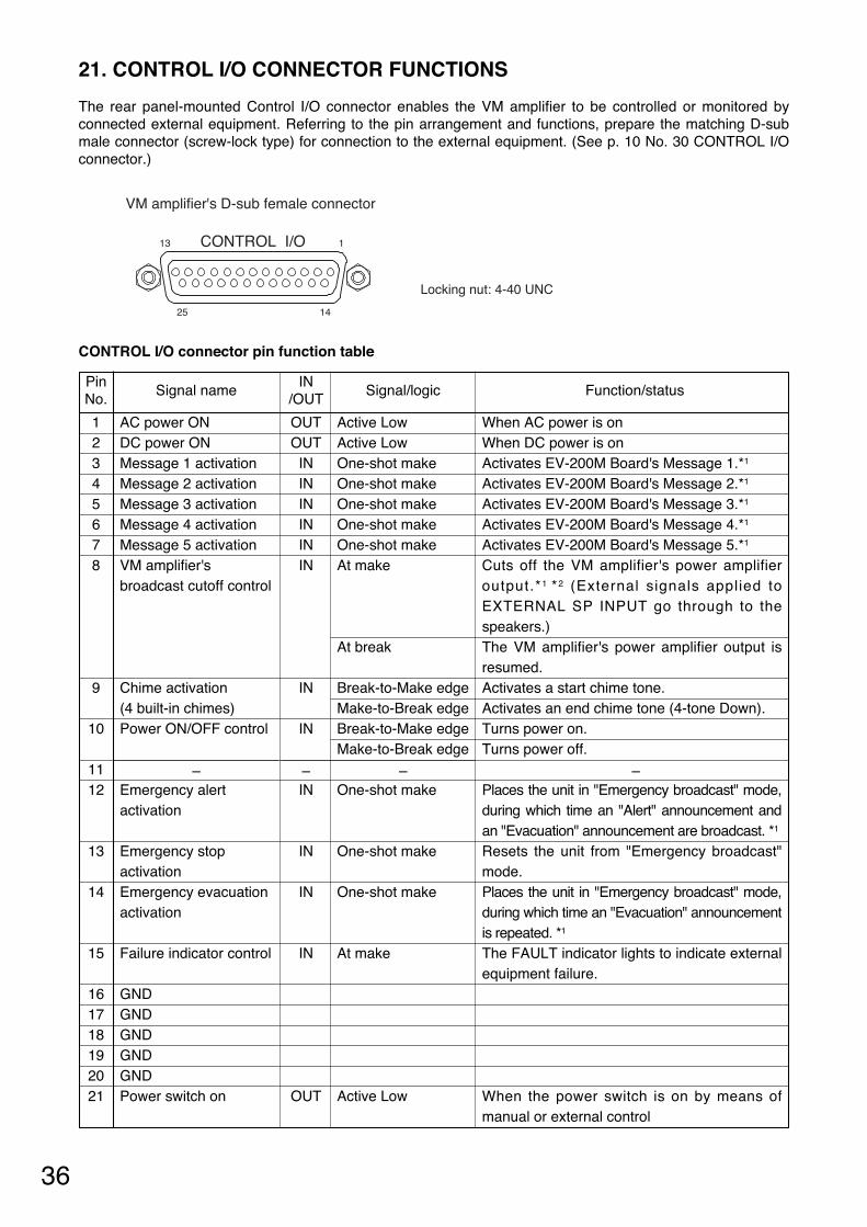
21. CONTROL I/O CONNECTOR FUNCTIONS
The rear panel-mounted Control I/O connector enables the VM amplifier to be controlled or monitored byconnected external equipment. Referring to the pin arrangement and functions, prepare the matching D-submale connector (screw-lock type) for connection to the external equipment. (See p. 10 No. 30 CONTROL I/Oconnector.)
CONTROL I/O connector pin function table
VM amplifier's D-sub female connector
13 1
25 14
CONTROL I/O
Locking nut: 4-40 UNC
Function/status
When AC power is on When DC power is on Activates EV-200M Board's Message 1.*1
Activates EV-200M Board's Message 2.*1
Activates EV-200M Board's Message 3.*1
Activates EV-200M Board's Message 4.*1
Activates EV-200M Board's Message 5.*1
Cuts off the VM amplifier's power amplifieroutput.*1 *2 (External signals applied toEXTERNAL SP INPUT go through to thespeakers.) The VM amplifier's power amplifier output isresumed. Activates a start chime tone. Activates an end chime tone (4-tone Down). Turns power on.Turns power off.
–Places the unit in "Emergency broadcast" mode,during which time an "Alert" announcement andan "Evacuation" announcement are broadcast. *1
Resets the unit from "Emergency broadcast"mode. Places the unit in "Emergency broadcast" mode,during which time an "Evacuation" announcementis repeated. *1
The FAULT indicator lights to indicate externalequipment failure.
When the power switch is on by means ofmanual or external control
Pin No.
1 2 3 4 5 6 7 8
9
10
1112
13
14
15
16 17 18 19 20 21
Signal name
AC power ON DC power ON Message 1 activation Message 2 activation Message 3 activation Message 4 activation Message 5 activation VM amplifier'sbroadcast cutoff control
Chime activation (4 built-in chimes)Power ON/OFF control
–Emergency alert activation
Emergency stop activation Emergency evacuation activation
Failure indicator control
GND GND GND GND GND Power switch on
IN/OUT
OUT OUT IN IN IN IN IN IN
IN
IN
–IN
IN
IN
IN
OUT
Signal/logic
Active Low Active Low One-shot make One-shot make One-shot make One-shot make One-shot make At make
At break
Break-to-Make edge Make-to-Break edge Break-to-Make edge Make-to-Break edge
–One-shot make
One-shot make
One-shot make
At make
Active Low
37
Function/status
When communications cannot be achievedbetween the RM-200M and the VM amplifieror between VM amplifiers (High state whencommunications are restored.) When the FAULT indicator lamp is on When an Emergency broadcast is performedby the VM amplifier or the external equipment.(See the description of Pin 8 VM amplifier'sbroadcast cutoff.) When the EV-200M Voice AnnouncementBoard fails.*1
Pin No.
22
23 24
25
Signal name
Communications error
Failure indication Emergency broadcaston
EV-200M's failure
IN/OUT
OUT
OUT OUT
OUT
Signal/logic
Active Low
Active Low Active Low
Active Low
*1 Requires installation of the optional EV-200M Voice Announcement Board.
*2 Use this pin to cut off the VM amplifier's power amplifier output to allow the "Emergency broadcast" initiatedby connected external equipment to go through.
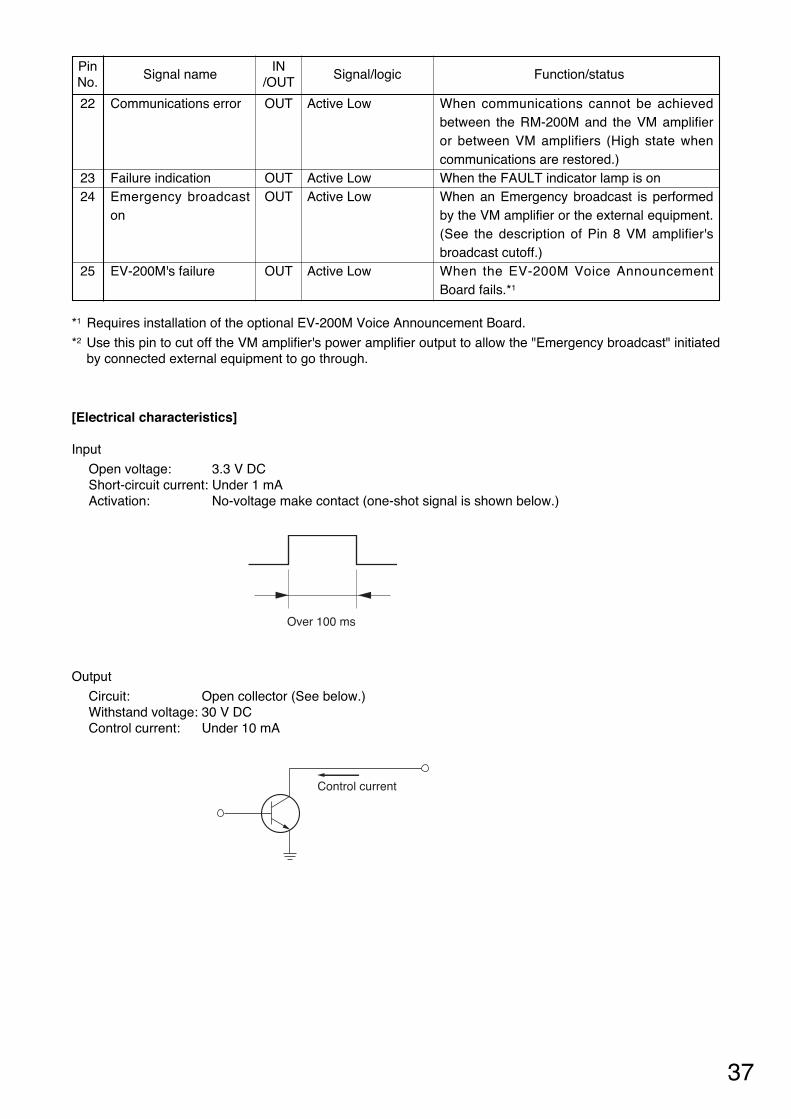
[Electrical characteristics]
Input
Open voltage: 3.3 V DC Short-circuit current: Under 1 mA Activation: No-voltage make contact (one-shot signal is shown below.)
Output
Circuit: Open collector (See below.) Withstand voltage: 30 V DC Control current: Under 10 mA
Over 100 ms
Control current
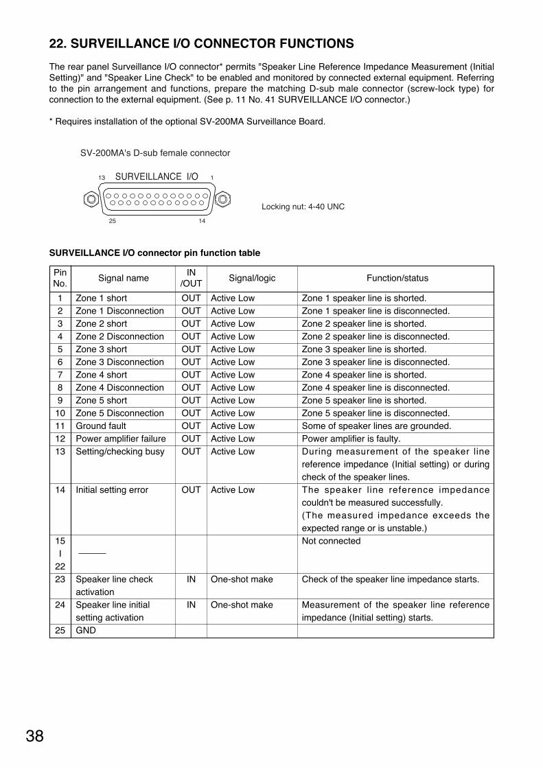
38
22. SURVEILLANCE I/O CONNECTOR FUNCTIONS
The rear panel Surveillance I/O connector* permits "Speaker Line Reference Impedance Measurement (InitialSetting)" and "Speaker Line Check" to be enabled and monitored by connected external equipment. Referringto the pin arrangement and functions, prepare the matching D-sub male connector (screw-lock type) forconnection to the external equipment. (See p. 11 No. 41 SURVEILLANCE I/O connector.)
* Requires installation of the optional SV-200MA Surveillance Board.
SURVEILLANCE I/O connector pin function table
Function/status
Zone 1 speaker line is shorted. Zone 1 speaker line is disconnected. Zone 2 speaker line is shorted. Zone 2 speaker line is disconnected. Zone 3 speaker line is shorted. Zone 3 speaker line is disconnected. Zone 4 speaker line is shorted. Zone 4 speaker line is disconnected. Zone 5 speaker line is shorted. Zone 5 speaker line is disconnected. Some of speaker lines are grounded. Power amplifier is faulty. During measurement of the speaker linereference impedance (Initial setting) or duringcheck of the speaker lines. The speaker l ine reference impedancecouldn't be measured successfully. (The measured impedance exceeds theexpected range or is unstable.) Not connected
Check of the speaker line impedance starts.
Measurement of the speaker line referenceimpedance (Initial setting) starts.
Pin No.
1 2 3 4 5 6 7 8 9 10 11 12 13
14
15 I
22 23
24
25
Signal name
Zone 1 short Zone 1 Disconnection Zone 2 short Zone 2 Disconnection Zone 3 short Zone 3 Disconnection Zone 4 short Zone 4 Disconnection Zone 5 short Zone 5 Disconnection Ground fault Power amplifier failure Setting/checking busy
Initial setting error
Speaker line check activation Speaker line initial setting activationGND
IN/OUT
OUT OUT OUT OUT OUT OUT OUT OUT OUT OUT OUT OUT OUT
OUT
IN
IN
Signal/logic
Active Low Active Low Active Low Active Low Active Low Active Low Active Low Active Low Active Low Active Low Active Low Active Low Active Low
Active Low
One-shot make
One-shot make
SV-200MA's D-sub female connector
13 1
25 14
SURVEILLANCE I/O
Locking nut: 4-40 UNC
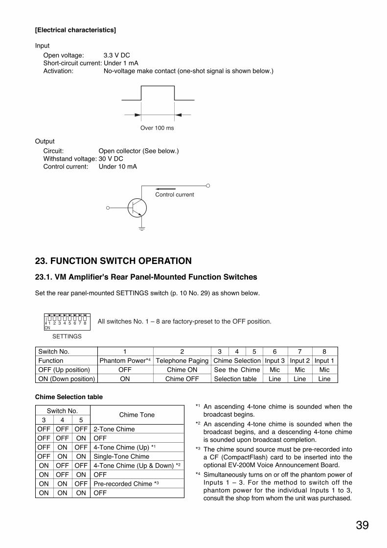
39
[Electrical characteristics]
Input
Open voltage: 3.3 V DC Short-circuit current: Under 1 mA Activation: No-voltage make contact (one-shot signal is shown below.)
Output
Circuit: Open collector (See below.) Withstand voltage: 30 V DC Control current: Under 10 mA
Over 100 ms
Control current
Chime Selection table *1 An ascending 4-tone chime is sounded when the
broadcast begins.
*2 An ascending 4-tone chime is sounded when thebroadcast begins, and a descending 4-tone chimeis sounded upon broadcast completion.
*3 The chime sound source must be pre-recorded intoa CF (CompactFlash) card to be inserted into theoptional EV-200M Voice Announcement Board.
*4 Simultaneously turns on or off the phantom power ofInputs 1 – 3. For the method to switch off thephantom power for the individual Inputs 1 to 3,consult the shop from whom the unit was purchased.
23. FUNCTION SWITCH OPERATION
23.1. VM Amplifier's Rear Panel-Mounted Function Switches
Set the rear panel-mounted SETTINGS switch (p. 10 No. 29) as shown below.
SETTINGS
All switches No. 1 – 8 are factory-preset to the OFF position.1 2ON
3 4 5 6 7 8
Switch No. 1 2 3 4 5 6 7 8 Function Phantom Power*4 Telephone Paging Chime Selection Input 3 Input 2 Input 1OFF (Up position) OFF Chime ON Mic Mic MicON (Down position) ON Chime OFF Line Line Line
Switch No.Chime Tone
3 4 5OFF OFF OFF 2-Tone Chime OFF OFF ON OFFOFF ON OFF 4-Tone Chime (Up) *1
OFF ON ON Single-Tone Chime ON OFF OFF 4-Tone Chime (Up & Down) *2
ON OFF ON OFF ON ON OFF Pre-recorded Chime *3
ON ON ON OFF
See the ChimeSelection table
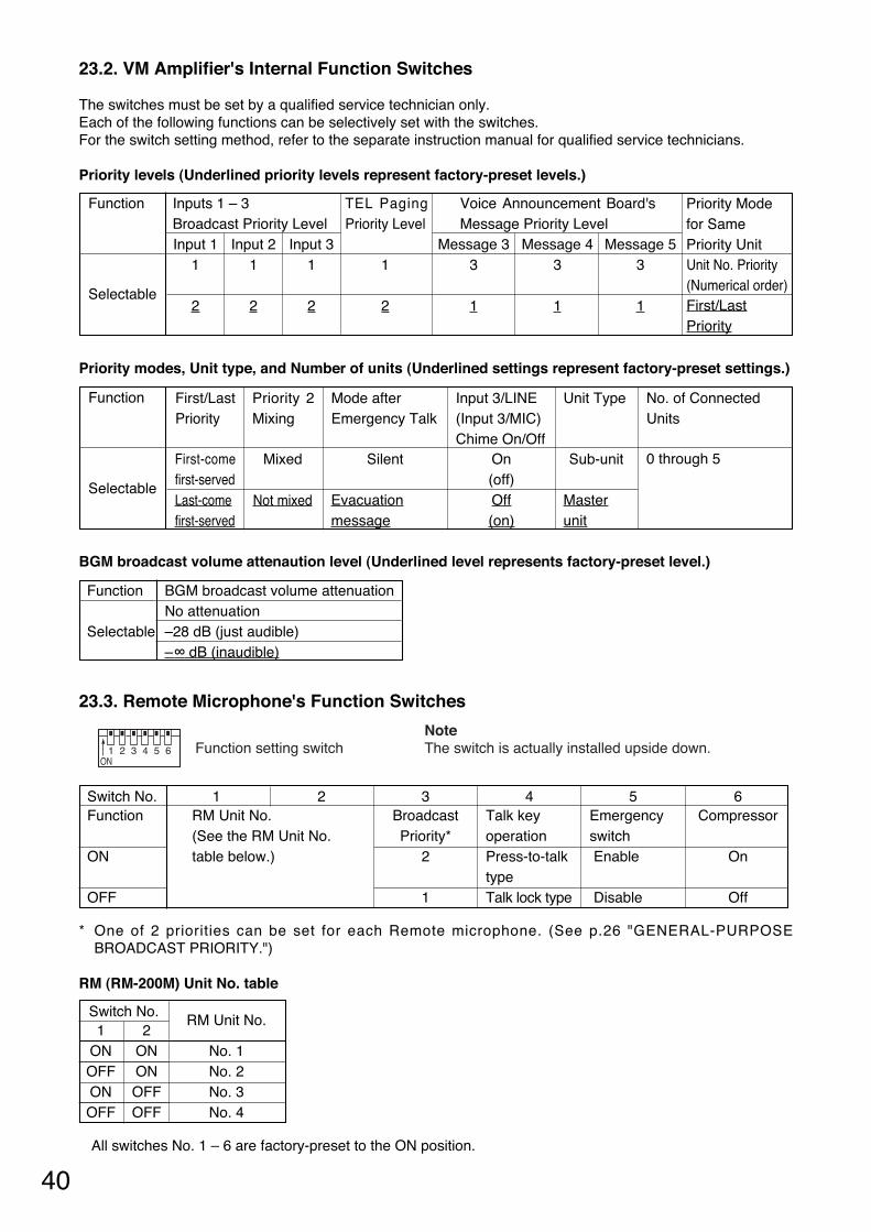
40
23.2. VM Amplifier's Internal Function Switches
The switches must be set by a qualified service technician only. Each of the following functions can be selectively set with the switches. For the switch setting method, refer to the separate instruction manual for qualified service technicians.
Priority levels (Underlined priority levels represent factory-preset levels.)
Priority modes, Unit type, and Number of units (Underlined settings represent factory-preset settings.)
BGM broadcast volume attenaution level (Underlined level represents factory-preset level.)
23.3. Remote Microphone's Function Switches
* One of 2 priorities can be set for each Remote microphone. (See p.26 "GENERAL-PURPOSEBROADCAST PRIORITY.")
RM (RM-200M) Unit No. table
All switches No. 1 – 6 are factory-preset to the ON position.
6 Compressor
On
Off
1 2ON
3 4 5 6 Function setting switch NoteThe switch is actually installed upside down.
Switch No. Function
ON
OFF
1 2 RM Unit No. (See the RM Unit No. table below.)
3 Broadcast Priority*
2
1
4 Talk key operationPress-to-talk type Talk lock type
5 Emergency switchEnable
Disable
RM Unit No.
No. 1No. 2No. 3No. 4
Switch No. 1 2
ON ONOFF ON ON OFFOFF OFF
Function
Input 1 Input 2 Input 3 Message 3 Message 4 Message 5 1 1 1 1 3 3 3
Selectable 2 2 2 2 1 1 1
Priority Mode for Same Priority Unit Unit No. Priority (Numerical order)First/LastPriority
Inputs 1 – 3 Broadcast Priority Level
Voice Announcement Board'sMessage Priority Level
TEL PagingPriority Level
Function
Mixed Silent On Sub-unit
Selectable (off)Off(on)
First/LastPriority
First-comefirst-served Last-comefirst-served
Not mixed Evacuationmessage
Masterunit
Priority 2Mixing
Mode after Emergency Talk
Input 3/LINE (Input 3/MIC) Chime On/Off
Unit Type No. of ConnectedUnits
0 through 5
Function BGM broadcast volume attenuation No attenuation
Selectable –28 dB (just audible) –∞ dB (inaudible)
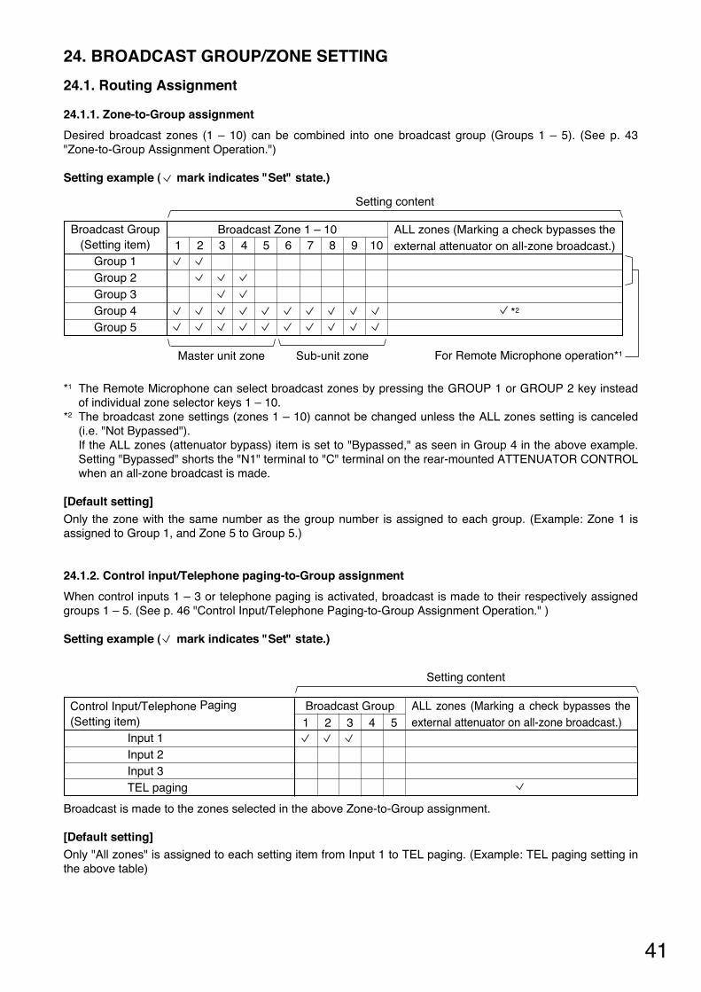
41
ALL zones (Marking a check bypasses theexternal attenuator on all-zone broadcast.)
*2
24. BROADCAST GROUP/ZONE SETTING
24.1. Routing Assignment
24.1.1. Zone-to-Group assignment
Desired broadcast zones (1 – 10) can be combined into one broadcast group (Groups 1 – 5). (See p. 43"Zone-to-Group Assignment Operation.")
Setting example ( mark indicates "Set" state.)
1 2 3 4 5 6 7 8 9 10Broadcast Group
(Setting item)Group 1 Group 2 Group 3 Group 4 Group 5
Broadcast Zone 1 – 10
Master unit zone
Setting content
Sub-unit zone For Remote Microphone operation*1
*1 The Remote Microphone can select broadcast zones by pressing the GROUP 1 or GROUP 2 key insteadof individual zone selector keys 1 – 10.
*2 The broadcast zone settings (zones 1 – 10) cannot be changed unless the ALL zones setting is canceled(i.e. "Not Bypassed"). If the ALL zones (attenuator bypass) item is set to "Bypassed," as seen in Group 4 in the above example.Setting "Bypassed" shorts the "N1" terminal to "C" terminal on the rear-mounted ATTENUATOR CONTROLwhen an all-zone broadcast is made.
[Default setting] Only the zone with the same number as the group number is assigned to each group. (Example: Zone 1 isassigned to Group 1, and Zone 5 to Group 5.)
24.1.2. Control input/Telephone paging-to-Group assignment
When control inputs 1 – 3 or telephone paging is activated, broadcast is made to their respectively assignedgroups 1 – 5. (See p. 46 "Control Input/Telephone Paging-to-Group Assignment Operation." )
Setting example ( mark indicates "Set" state.)
Broadcast is made to the zones selected in the above Zone-to-Group assignment.
[Default setting] Only "All zones" is assigned to each setting item from Input 1 to TEL paging. (Example: TEL paging setting inthe above table)
ALL zones (Marking a check bypasses theexternal attenuator on all-zone broadcast.) 51 2 3 4
Control Input/Telephone Paging (Setting item)
Input 1 Input 2 Input 3 TEL paging
Broadcast Group
Setting content

42
24.1.3. Recorded Message-to-Group assignment
Activated messages (1 – 5) are broadcast to their respectively assigned groups 1 – 5. (See p. 48 "RecordedMessage-to-Group Assignment Operation.")
Setting example ( mark indicates "Set" state.)
Messages are broadcast to the zones selected in the above Zone-to-Group assignment.
[Default setting] Only "All zones" is assigned to each of Messages 1 – 5. (Example: Message 3 setting in the above table)
24.2. Operating Keys
*1 See p. 45 "Indicator status." *2 Function as the indicators or keys for the setting items (Group 1 – 5, Message 1 – 5, etc.) as well according
to the setting steps.
• Note that the Sub-unit's zone selector keys function as the ZONE 6 through ZONE 10 keys.
• The figure above shows a 10-zone broadcast system where master unit and sub-unit are linked together. A 5-zone broadcast system requires the master unit only.
Master VM amplifier
Reset key ALL key
POWER switch
ZONE 1 – 5 indicators*1 *2
ALL indicator
LINK connector (rear)
ZONE 1 – 5 keys*2
Sub-VM amplifierZONE 6 – 10 indicators
LINK connector (rear)
ZONE 6 – 10 keys
ALL zones (Marking a check bypasses theexternal attenuator on all-zone broadcast.)1 2 3 4 5
Recorded Message(Setting item) Message 1 Message 2 Message 3 Message 4 Message 5
Broadcast Group
Setting content
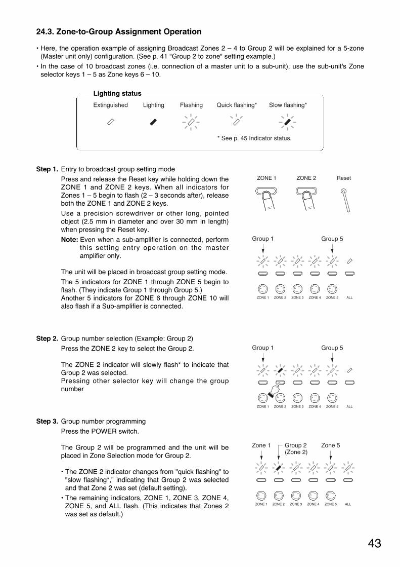
43
24.3. Zone-to-Group Assignment Operation
• Here, the operation example of assigning Broadcast Zones 2 – 4 to Group 2 will be explained for a 5-zone(Master unit only) configuration. (See p. 41 "Group 2 to zone" setting example.)
• In the case of 10 broadcast zones (i.e. connection of a master unit to a sub-unit), use the sub-unit's Zoneselector keys 1 – 5 as Zone keys 6 – 10.
Step 1. Entry to broadcast group setting mode
Press and release the Reset key while holding down theZONE 1 and ZONE 2 keys. When all indicators forZones 1 – 5 begin to flash (2 – 3 seconds after), releaseboth the ZONE 1 and ZONE 2 keys.
Use a precision screwdriver or other long, pointedobject (2.5 mm in diameter and over 30 mm in length)when pressing the Reset key.
Note: Even when a sub-amplifier is connected, performthis sett ing entry operation on the masteramplifier only.
The unit will be placed in broadcast group setting mode.
The 5 indicators for ZONE 1 through ZONE 5 begin toflash. (They indicate Group 1 through Group 5.) Another 5 indicators for ZONE 6 through ZONE 10 willalso flash if a Sub-amplifier is connected.
Step 2. Group number selection (Example: Group 2)
Press the ZONE 2 key to select the Group 2.
The ZONE 2 indicator will slowly flash* to indicate thatGroup 2 was selected. Pressing other selector key will change the groupnumber
Step 3. Group number programming
Press the POWER switch.
The Group 2 will be programmed and the unit will beplaced in Zone Selection mode for Group 2.
• The ZONE 2 indicator changes from "quick flashing" to"slow flashing*," indicating that Group 2 was selectedand that Zone 2 was set (default setting).
• The remaining indicators, ZONE 1, ZONE 3, ZONE 4,ZONE 5, and ALL flash. (This indicates that Zones 2was set as default.)
ZONE 1 ZONE 2 Reset
Extinguished Lighting Flashing Quick flashing* Slow flashing*
* See p. 45 Indicator status.
Lighting status
ZONE 1 ZONE 2 ZONE 3 ZONE 4 ZONE 5 ALL
Group 1 Group 5
ZONE 1 ZONE 2 ZONE 3 ZONE 4 ZONE 5 ALL
Group 1 Group 5
ZONE 1 ZONE 2 ZONE 3 ZONE 4 ZONE 5 ALL
Zone 1 Group 2(Zone 2)
Zone 5
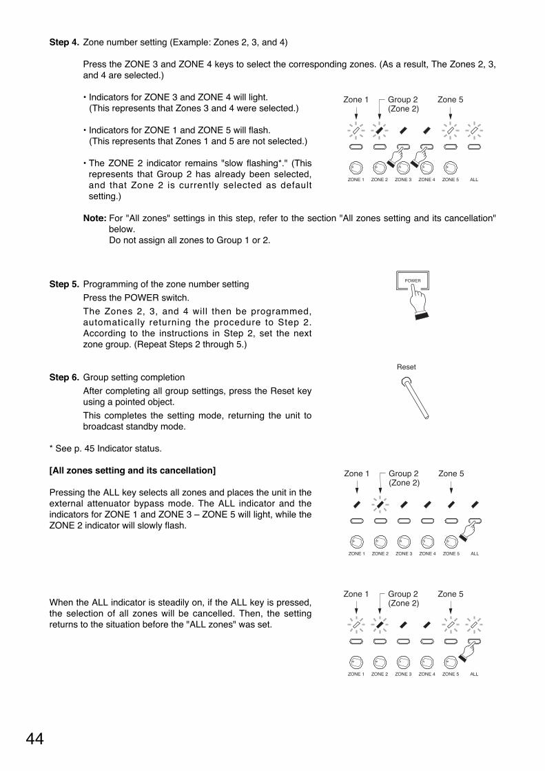
44
Step 4. Zone number setting (Example: Zones 2, 3, and 4)
Press the ZONE 3 and ZONE 4 keys to select the corresponding zones. (As a result, The Zones 2, 3,and 4 are selected.)
• Indicators for ZONE 3 and ZONE 4 will light. (This represents that Zones 3 and 4 were selected.)
• Indicators for ZONE 1 and ZONE 5 will flash. (This represents that Zones 1 and 5 are not selected.)
• The ZONE 2 indicator remains "slow flashing*." (Thisrepresents that Group 2 has already been selected,and that Zone 2 is currently selected as defaultsetting.)
Note: For "All zones" settings in this step, refer to the section "All zones setting and its cancellation"below. Do not assign all zones to Group 1 or 2.
Step 5. Programming of the zone number setting
Press the POWER switch.
The Zones 2, 3, and 4 will then be programmed,automatically returning the procedure to Step 2.According to the instructions in Step 2, set the nextzone group. (Repeat Steps 2 through 5.)
Step 6. Group setting completion
After completing all group settings, press the Reset keyusing a pointed object.
This completes the setting mode, returning the unit tobroadcast standby mode.
* See p. 45 Indicator status.
[All zones setting and its cancellation]
Pressing the ALL key selects all zones and places the unit in theexternal attenuator bypass mode. The ALL indicator and theindicators for ZONE 1 and ZONE 3 – ZONE 5 will light, while theZONE 2 indicator will slowly flash.
When the ALL indicator is steadily on, if the ALL key is pressed,the selection of all zones will be cancelled. Then, the settingreturns to the situation before the "ALL zones" was set.
ZONE 1 ZONE 2 ZONE 3 ZONE 4 ZONE 5 ALL
Zone 1 Group 2(Zone 2)
Zone 5
POWER
Reset
ZONE 1 ZONE 2 ZONE 3 ZONE 4 ZONE 5 ALL
Zone 1 Group 2(Zone 2)
Zone 5
ZONE 1 ZONE 2 ZONE 3 ZONE 4 ZONE 5 ALL
Zone 1 Group 2(Zone 2)
Zone 5
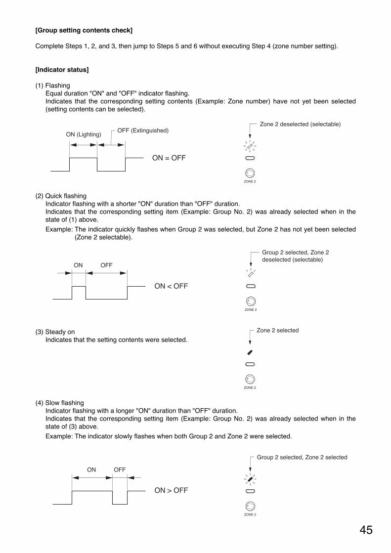
45
[Group setting contents check]
Complete Steps 1, 2, and 3, then jump to Steps 5 and 6 without executing Step 4 (zone number setting).
[Indicator status]
(1) Flashing Equal duration "ON" and "OFF" indicator flashing. Indicates that the corresponding setting contents (Example: Zone number) have not yet been selected(setting contents can be selected).
(2) Quick flashing Indicator flashing with a shorter "ON" duration than "OFF" duration. Indicates that the corresponding setting item (Example: Group No. 2) was already selected when in thestate of (1) above.
Example: The indicator quickly flashes when Group 2 was selected, but Zone 2 has not yet been selected(Zone 2 selectable).
(3) Steady on Indicates that the setting contents were selected.
(4) Slow flashing Indicator flashing with a longer "ON" duration than "OFF" duration.Indicates that the corresponding setting item (Example: Group No. 2) was already selected when in thestate of (3) above.
Example: The indicator slowly flashes when both Group 2 and Zone 2 were selected.
ZONE 2
ON OFF
Group 2 selected, Zone 2 deselected (selectable)
ON < OFF
ZONE 2
Group 2 selected, Zone 2 selected
ON > OFF
ON OFF
ZONE 2
Zone 2 selected
ZONE 2
ON (Lighting)OFF (Extinguished)
Zone 2 deselected (selectable)
ON = OFF
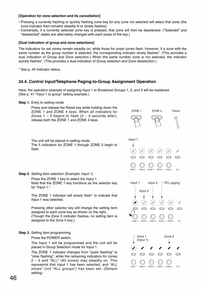
46
[Operation for zone selection and its cancellation]
• Pressing a currently flashing or quickly flashing zone key for any zone not selected will select that zone (thezone indicator then remains steadily lit or slowly flashes).
• Conversely, if a currently selected zone key is pressed, that zone will then be deselected. ("Selected" and"deselected" states are alternately changed with each press of the key.)
[Dual indication of group and zone selections]
The indicators for set zones remain steadily on, while those for unset zones flash. However, if a zone with thesame number as the group number is selected, the corresponding indicator slowly flashes*. (This provides adual indication of Group and Zone selection.) When the same number zone is not selected, the indicatorquickly flashes*. (This provides a dual indication of Group selection and Zone deselection.)
* See p. 45 Indicator status.
24.4. Control Input/Telephone Paging-to-Group Assignment Operation
Here, the operation example of assigning Input 1 to Broadcast Groups 1, 2, and 3 will be explained. (See p. 41 "Input 1 to group" setting example.)
Step 1. Entry to setting mode
Press and release the Reset key while holding down theZONE 1 and ZONE 4 keys. When all indicators forZones 1 – 5 begins to flash (2 – 3 seconds after),release both the ZONE 1 and ZONE 4 keys.
The unit will be placed in setting mode. The 5 indicators for ZONE 1 through ZONE 5 begin toflash.
Step 2. Setting item selection (Example: Input 1)
Press the ZONE 1 key to select the Input 1. Note that the ZONE 1 key functions as the selector keyfor "Input 1."
The ZONE 1 indicator will slowly flash* to indicate thatInput 1 was selected.
Pressing other selector key will change the setting itemassigned to each zone key as shown on the right. (Though the Zone 5 indicator flashes, no setting item isassigned to the Zone 5 key.)
Step 3. Setting item programming
Press the POWER switch.
The Input 1 will be programmed and the unit will beplaced in Group Selection mode for Input 1.
The ZONE 1 indicator changes from "quick flashing" to"slow flashing", while the remaining indicators for zones2 – 5 and "ALL" (All zones) stay steadily on. Thisrepresents that Input 1 has been selected, and "ALLzones" (not "ALL groups") has been set. (Defaultsetting)
ZONE 1 ZONE 4 Reset
ZONE 1 ZONE 2 ZONE 3 ZONE 4 ZONE 5 ALL
Input 1
ZONE 1 ZONE 2 ZONE 3 ZONE 4 ZONE 5 ALL
Input 1
Input 2
Input 3 TEL paging
ZONE 1 ZONE 2 ZONE 3 ZONE 4 ZONE 5 ALL
Zone 1(Input 1)
Zone 5
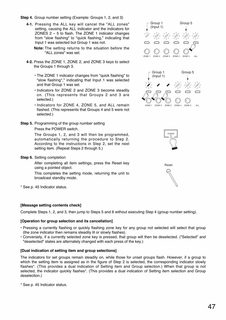
47
Step 4. Group number setting (Example: Groups 1, 2, and 3)
4-1. Pressing the ALL key will cancel the "ALL zones"setting, causing the ALL indicator and the indicators forZONES 2 – 5 to flash. The ZONE 1 indicator changesfrom "slow flashing" to "quick flashing," indicating thatInput 1 was selected but Group 1 was not.
Note: The setting returns to the situation before the"ALL zones" was set.
4-2. Press the ZONE 1, ZONE 2, and ZONE 3 keys to selectthe Groups 1 through 3.
• The ZONE 1 indicator changes from "quick flashing" to"slow flashing*," indicating that Input 1 was selectedand that Group 1 was set.
• Indicators for ZONE 2 and ZONE 3 become steadilyon. (This represents that Groups 2 and 3 areselected.)
• Indicators for ZONE 4, ZONE 5, and ALL remainflashed. (This represents that Groups 4 and 5 were notselected.)
Step 5. Programming of the group number setting
Press the POWER switch.
The Groups 1, 2, and 3 will then be programmed,automatically returning the procedure to Step 2.According to the instructions in Step 2, set the nextsetting item. (Repeat Steps 2 through 5.)
Step 6. Setting completion
After completing all item settings, press the Reset keyusing a pointed object.
This completes the setting mode, returning the unit tobroadcast standby mode.
* See p. 45 Indicator status.
[Message setting contents check]
Complete Steps 1, 2, and 3, then jump to Steps 5 and 6 without executing Step 4 (group number setting).
[Operation for group selection and its cancellation]
• Pressing a currently flashing or quickly flashing zone key for any group not selected will select that group(the zone indicator then remains steadily lit or slowly flashes).
• Conversely, if a currently selected zone key is pressed, that group will then be deselected. ("Selected" and"deselected" states are alternately changed with each press of the key.)
[Dual indication of setting item and group selections]
The indicators for set groups remain steadily on, while those for unset groups flash. However, if a group towhich the setting item is assigned as in the figure of Step 2 is selected, the corresponding indicator slowlyflashes*. (This provides a dual indication of Setting item and Group selection.) When that group is notselected, the indicator quickly flashes*. (This provides a dual indication of Setting item selection and Groupdeselection.)
* See p. 45 Indicator status.
ZONE 1 ZONE 2 ZONE 3 ZONE 4 ZONE 5 ALL
Group 1(Input 1)
Group 5
ZONE 1 ZONE 2 ZONE 3 ZONE 4 ZONE 5 ALL
Group 1(Input 1)
Group 5
POWER
Reset

48
24.5. Recorded Message-to-Group Assignment Operation
Here, the operation example of assigning Recorded Message 1 to Broadcast Groups 1, 3, and 4 will beexplained. (See p. 42 "Message 1 to group" setting example.)
Step 1. Entry to recorded message setting mode
Press and release the Reset key while holding down theZONE 1 and ZONE 3 keys. When all indicators forZones 1 – 5 begins to flash (2 – 3 seconds after),release both the ZONE 1 and ZONE 3 keys.
The unit will be placed in recorded message settingmode. The 5 indicators for ZONE 1 through ZONE 5 begin toflash. (They indicate Message 1 through Message 5.)
Operations of Steps 2 – 6 described hereinafter are the same as those described in the previous section"Control Input/Telephone Paging-to-Group Assignment Operation." However, read 4 setting items of inputs 1 – 3and TEL paging as Messages 1 – 4, and note that Message 5 is assigned to ZONE 5 key in step 2.
Shown on the right is the status of each indicator that resultsfrom the group number setting (Example. Groups 1, 3, and 4)performed in Step 4.
ZONE 1 ZONE 3 Reset
ZONE 1 ZONE 2 ZONE 3 ZONE 4 ZONE 5 ALL
Message 1 Message 5
ZONE 1 ZONE 2 ZONE 3 ZONE 4 ZONE 5 ALL
Group 1(Message 1)
Group 5
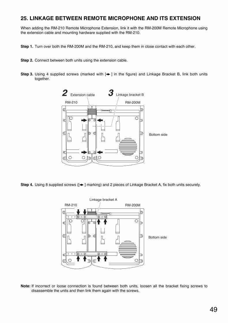
49
25. LINKAGE BETWEEN REMOTE MICROPHONE AND ITS EXTENSION
When adding the RM-210 Remote Microphone Extension, link it with the RM-200M Remote Microphone usingthe extension cable and mounting hardware supplied with the RM-210.
Step 1. Turn over both the RM-200M and the RM-210, and keep them in close contact with each other.
Step 2. Connect between both units using the extension cable.
Step 3. Using 4 supplied screws (marked with [ ] in the figure) and Linkage Bracket B, link both unitstogether.
Step 4. Using 8 supplied screws ([ ] marking) and 2 pieces of Linkage Bracket A, fix both units securely.
Note: If incorrect or loose connection is found between both units, loosen all the bracket fixing screws todisassemble the units and then link them again with the screws.
Extension cable
RM-210 RM-200M
Linkage bracket B32
Bottom side
Linkage bracket A
RM-210 RM-200M
Bottom side
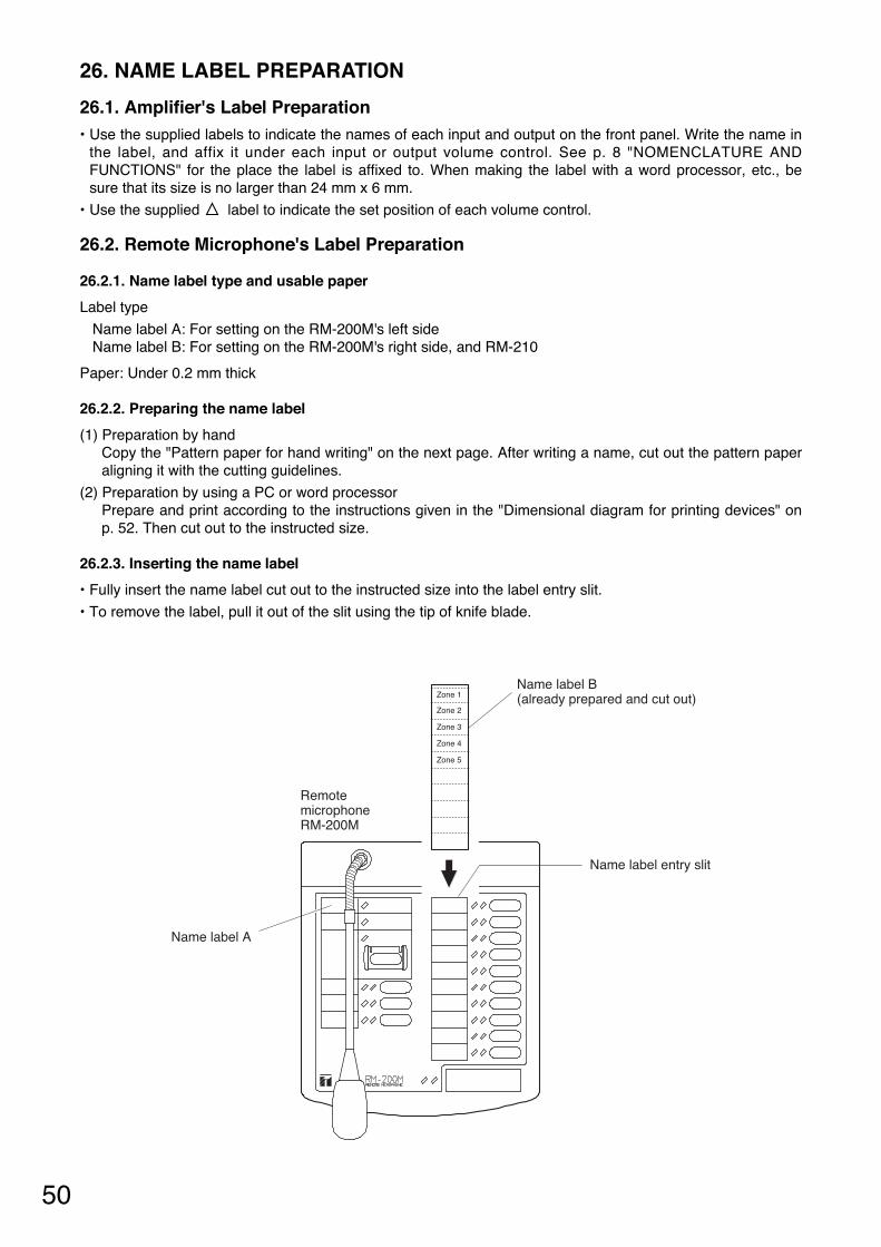
50
26. NAME LABEL PREPARATION
26.1. Amplifier's Label Preparation • Use the supplied labels to indicate the names of each input and output on the front panel. Write the name in
the label, and affix it under each input or output volume control. See p. 8 "NOMENCLATURE ANDFUNCTIONS" for the place the label is affixed to. When making the label with a word processor, etc., besure that its size is no larger than 24 mm x 6 mm.
• Use the supplied label to indicate the set position of each volume control.
26.2. Remote Microphone's Label Preparation
26.2.1. Name label type and usable paper
Label type
Name label A: For setting on the RM-200M's left side Name label B: For setting on the RM-200M's right side, and RM-210
Paper: Under 0.2 mm thick
26.2.2. Preparing the name label
(1) Preparation by hand Copy the "Pattern paper for hand writing" on the next page. After writing a name, cut out the pattern paperaligning it with the cutting guidelines.
(2) Preparation by using a PC or word processor Prepare and print according to the instructions given in the "Dimensional diagram for printing devices" onp. 52. Then cut out to the instructed size.
26.2.3. Inserting the name label
• Fully insert the name label cut out to the instructed size into the label entry slit.
• To remove the label, pull it out of the slit using the tip of knife blade.
RemotemicrophoneRM-200M
Zone 1
Zone 2
Zone 3
Zone 4
Zone 5
Name label entry slit
Name label B(already prepared and cut out)
Name label A
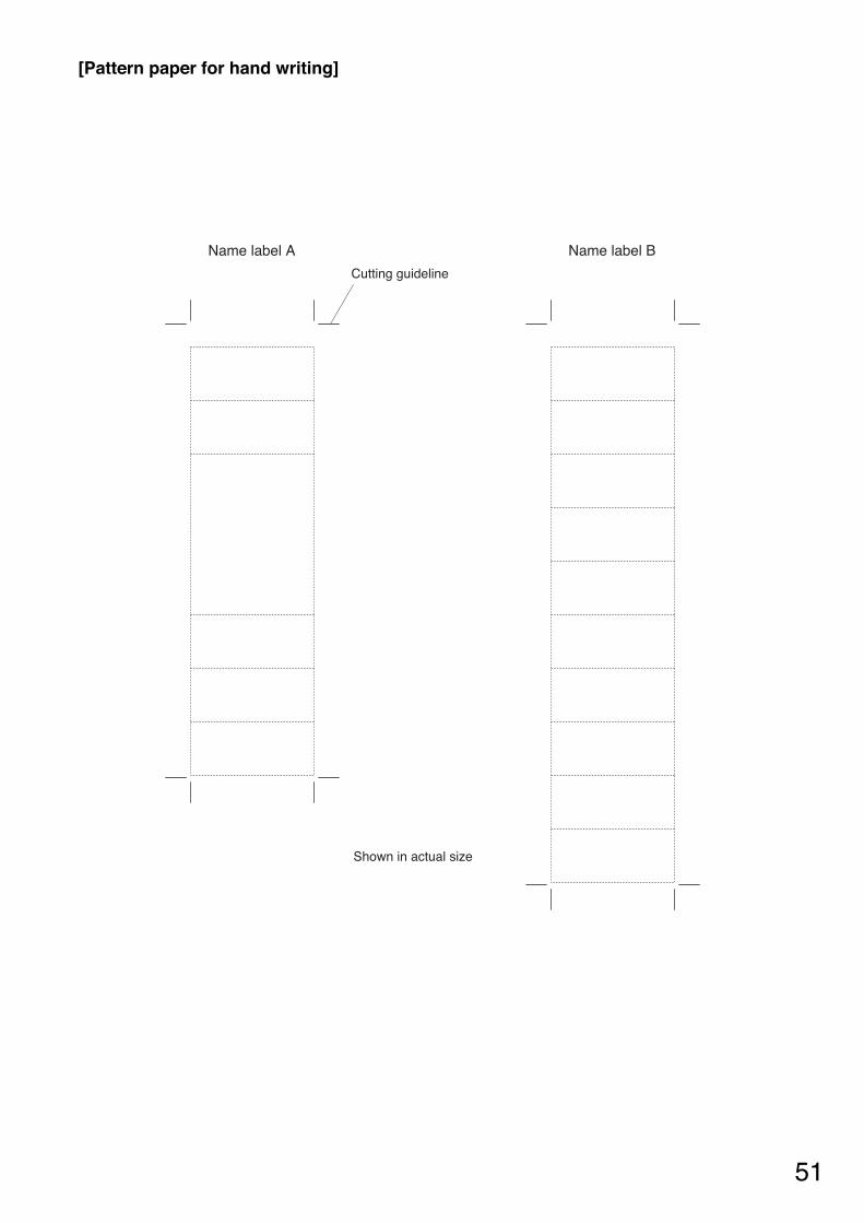
51
[Pattern paper for hand writing]
Name label A Name label B
Cutting guideline
Shown in actual size
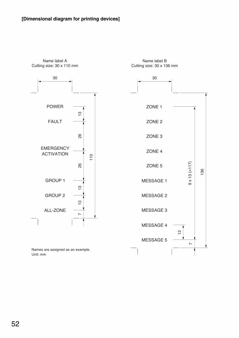
52
[Dimensional diagram for printing devices]
Name label ACutting size: 30 x 110 mm
Name label BCutting size: 30 x 136 mm
30 3026
2613
13
79
x 13
(=
117)
136
1313
7
110
POWER
FAULT
EMERGENCYACTIVATION
GROUP 1
GROUP 2
ALL-ZONE
ZONE 2
ZONE 3
ZONE 4
ZONE 5
MESSAGE 1
MESSAGE 2
MESSAGE 3
MESSAGE 4
MESSAGE 5
ZONE 1
Names are assigned as an example.Unit: mm
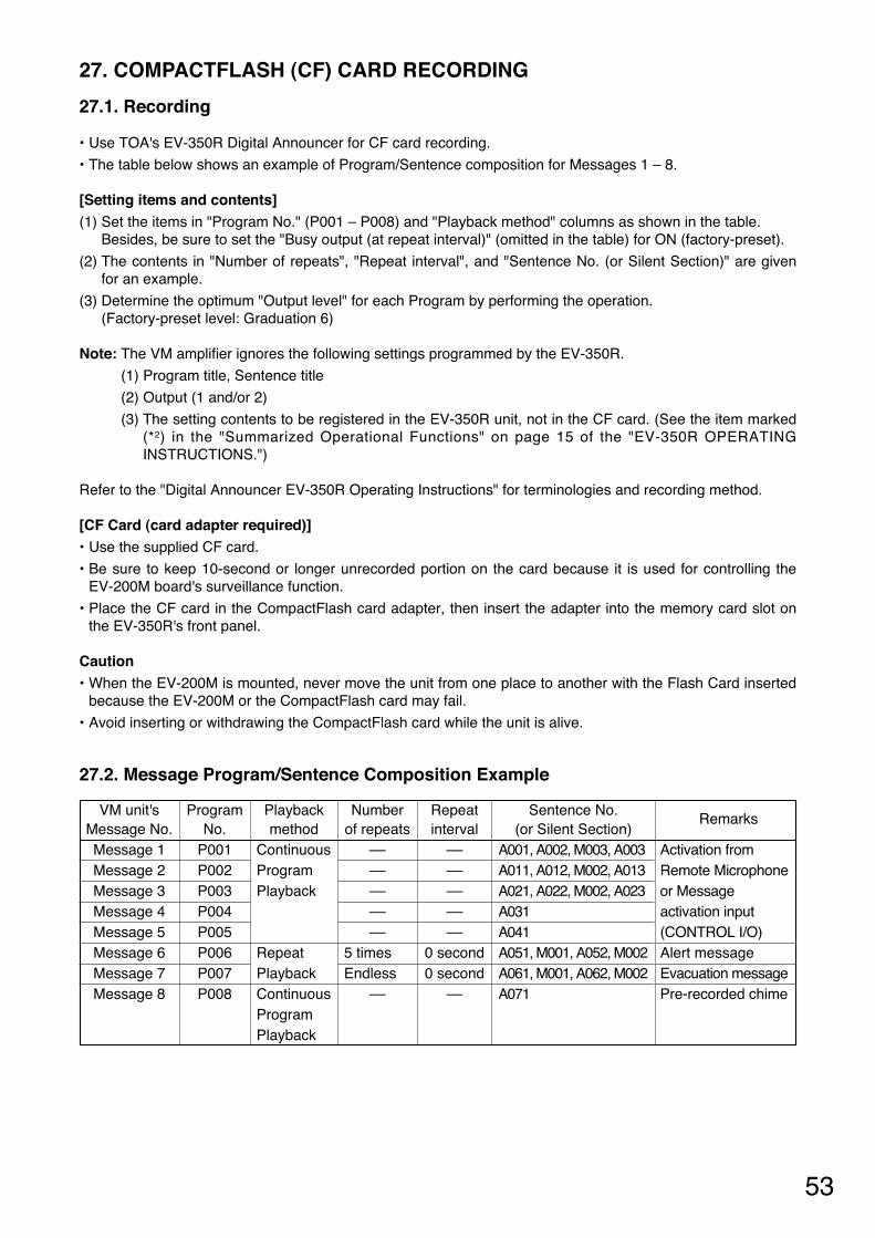
53
27. COMPACTFLASH (CF) CARD RECORDING
27.1. Recording
• Use TOA's EV-350R Digital Announcer for CF card recording.
• The table below shows an example of Program/Sentence composition for Messages 1 – 8.
[Setting items and contents] (1) Set the items in "Program No." (P001 – P008) and "Playback method" columns as shown in the table.
Besides, be sure to set the "Busy output (at repeat interval)" (omitted in the table) for ON (factory-preset).
(2) The contents in "Number of repeats", "Repeat interval", and "Sentence No. (or Silent Section)" are givenfor an example.
(3) Determine the optimum "Output level" for each Program by performing the operation. (Factory-preset level: Graduation 6)
Note: The VM amplifier ignores the following settings programmed by the EV-350R.
(1) Program title, Sentence title
(2) Output (1 and/or 2)
(3) The setting contents to be registered in the EV-350R unit, not in the CF card. (See the item marked(*2) in the "Summarized Operational Functions" on page 15 of the "EV-350R OPERATINGINSTRUCTIONS.")
Refer to the "Digital Announcer EV-350R Operating Instructions" for terminologies and recording method.
[CF Card (card adapter required)] • Use the supplied CF card.
• Be sure to keep 10-second or longer unrecorded portion on the card because it is used for controlling theEV-200M board's surveillance function.
• Place the CF card in the CompactFlash card adapter, then insert the adapter into the memory card slot onthe EV-350R's front panel.
Caution • When the EV-200M is mounted, never move the unit from one place to another with the Flash Card inserted
because the EV-200M or the CompactFlash card may fail.
• Avoid inserting or withdrawing the CompactFlash card while the unit is alive.
27.2. Message Program/Sentence Composition Example
Remarks
Activation fromRemote Microphoneor Messageactivation input(CONTROL I/O) Alert message Evacuation message Pre-recorded chime
VM unit's Message No. Message 1 Message 2 Message 3 Message 4 Message 5 Message 6 Message 7 Message 8
Playback method
Continuous Program Playback
Repeat Playback Continuous Program Playback
Number of repeats
–– –– –– –– ––
5 times Endless
––
Repeat interval
–– –– –– –– ––
0 second 0 second
––
Sentence No. (or Silent Section)
A001, A002, M003, A003 A011, A012, M002, A013 A021, A022, M002, A023 A031 A041 A051, M001, A052, M002 A061, M001, A062, M002 A071
Program No.
P001 P002 P003 P004 P005 P006 P007 P008
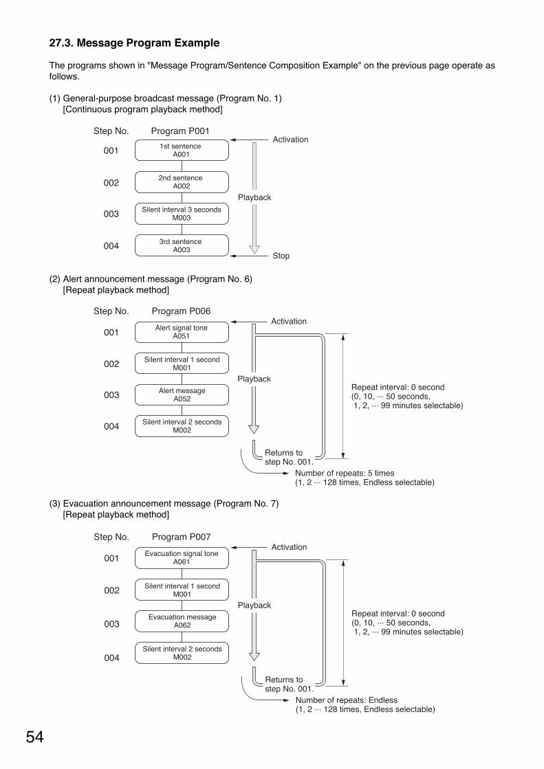
54
27.3. Message Program Example
The programs shown in "Message Program/Sentence Composition Example" on the previous page operate asfollows.
(1) General-purpose broadcast message (Program No. 1) [Continuous program playback method]
(2) Alert announcement message (Program No. 6) [Repeat playback method]
(3) Evacuation announcement message (Program No. 7) [Repeat playback method]
Step No.
001
Playback
002
003
004Stop
ActivationProgram P001
Silent interval 3 secondsM003
1st sentence A001
2nd sentence A002
3rd sentence A003
Returns to step No. 001.
001
002
003
004
Step No.
Alert signal toneA051
Program P006
Alert messageA052
Silent interval 1 secondM001
Silent interval 2 secondsM002
Activation
Repeat interval: 0 second(0, 10, ... 50 seconds, 1, 2, ... 99 minutes selectable)
Playback
Number of repeats: 5 times(1, 2 ... 128 times, Endless selectable)
Returns to step No. 001.
001
002
003
004
Step No.
Evacuation signal toneA061
Program P007
Evacuation messageA062
Silent interval 1 secondM001
Silent interval 2 secondsM002
Activation
Repeat interval: 0 second(0, 10, ... 50 seconds, 1, 2, ... 99 minutes selectable)
Playback
Number of repeats: Endless (1, 2 ... 128 times, Endless selectable)
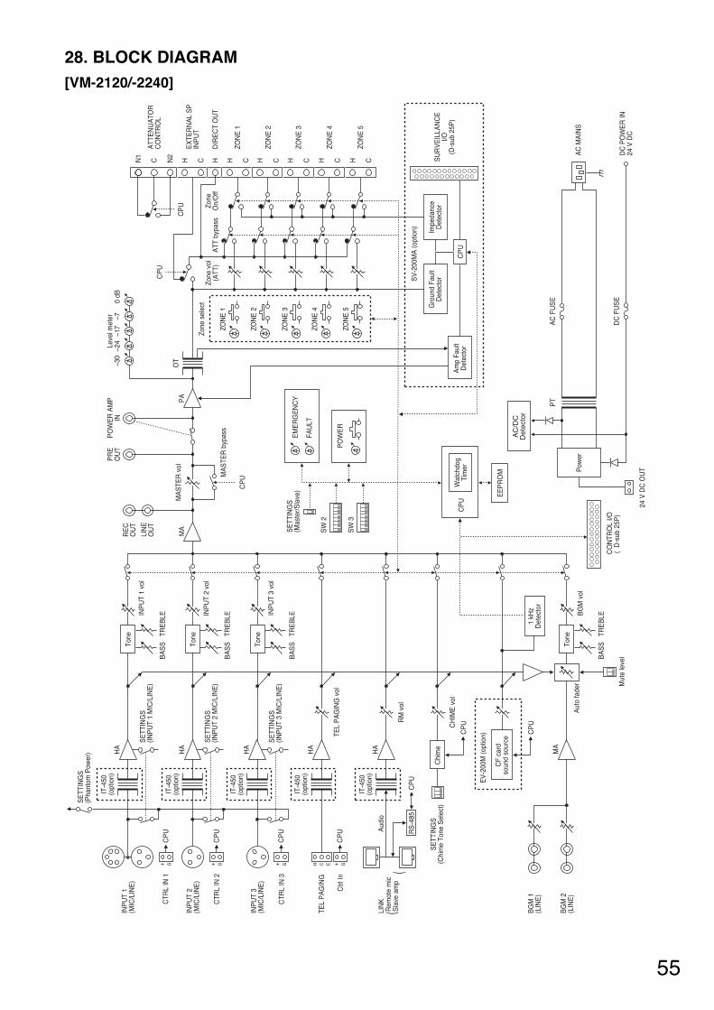
55
28. BLOCK DIAGRAM [VM-2120/-2240]
IT-4
50(o
ptio
n)
SE
TTIN
GS
(P
hant
om P
ower
)
SE
TTIN
GS
(IN
PU
T 1
MIC
/LIN
E)
SE
TTIN
GS
(IN
PU
T 2
MIC
/LIN
E)
SE
TTIN
GS
(IN
PU
T 3
MIC
/LIN
E)
HA
IT-4
50(o
ptio
n)H
A
G+C
PU
G+C
PU
IT-4
50(o
ptio
n)H
A
IT-4
50(o
ptio
n)H
A
IT-4
50(o
ptio
n)
OT
HA
MA
G+C
PU
G+C EH
CP
U RS
-485
CP
U
CP
U
CP
U
Aud
io
CTR
L IN
1
CTR
L IN
2
CTR
L IN
3
TEL
PA
GIN
G
INP
UT
3(M
IC/L
INE
)
BG
M 1
(LIN
E)
BG
M 2
(LIN
E)
INP
UT
2(M
IC/L
INE
)
INP
UT
1(M
IC/L
INE
)
Ctrl
In
LIN
K R
emot
e m
ic S
lave
am
p(
(
Chi
me
Tone
CF
card
soun
d so
urce
1 kH
zD
etec
tor
SE
TTIN
GS
(Chi
me
Tone
Sel
ect)
EV
-200
M (o
ptio
n)
Aut
o fa
der M
ute
leve
lBA
SS
TRE
BLEB
GM
vol
Tone
BA
SS
TRE
BLEIN
PU
T 1
vol
Tone
BA
SS
TRE
BLEIN
PU
T 2
vol
Tone
BA
SS
TRE
BLEIN
PU
T 3
vol
MA
RE
CO
UT
PR
EO
UT
PO
WE
R A
MP
IN
LIN
EO
UT
MA
STE
R v
ol
MA
STE
R b
ypas
s
CP
U
PA
Leve
l met
er–3
0–2
4–1
7–7
0 dB
ZON
E 1
Zone
sel
ect
Zone
vol
(ATT
)A
TT b
ypas
sZo
neO
n/O
ff
ZON
E 2
ZON
E 3
ZON
E 4
ZON
E 5
CP
U
CP
U
N1
ATT
EN
UA
TOR
CO
NTR
OL
EX
TER
NA
L S
PIN
PU
T
DIR
EC
T O
UT
ZON
E 1
ZON
E 2
ZON
E 3
Gro
und
Faul
tD
etec
tor
Impe
danc
eD
etec
tor
Am
p Fa
ult
Det
ecto
rW
atch
dog
Tim
er
AC
/DC
Det
ecto
r
ZON
E 4
ZON
E 5
N2
C CH CH CH CH CH CHH
SV
-200
MA
(opt
ion)
SU
RV
EIL
LAN
CE
I/O(D
-sub
25P
)C
PU
CP
U
EE
PR
OM
SW
2
SE
TTIN
GS
(Mas
ter/S
lave
)
SW
3
PO
WE
R
EM
ER
GE
NC
Y
FAU
LT
AC
MA
INS
AC
FU
SE
DC
FU
SE
DC
PO
WE
R IN
24 V
DC
PT
Pow
er
CO
NTR
OL
I/O(
D-s
ub 2
5P)
24 V
DC
OU
T
TEL
PA
GIN
G v
ol
RM
vol
CH
IME
vol
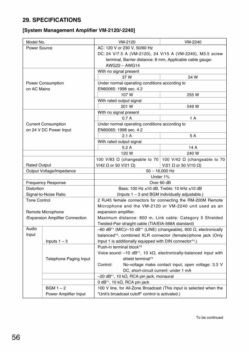
56
VM-2120 VM-2240AC: 120 V or 230 V, 50/60 HzDC: 24 V/7.5 A (VM-2120), 24 V/15 A (VM-2240), M3.5 screw
terminal, Barrier distance: 8 mm, Applicable cable gauge: AWG22 – AWG14
With no signal present 37 W 54 W
Under normal operating conditions according to EN60065: 1998 sec. 4.2
107 W 255 W With rated output signal
201 W 549 W With no signal present
0.7 A 1 A Under normal operating conditions according to EN60065: 1998 sec. 4.2
2.1 A 5 A With rated output signal
5.2 A 14 A 120 W 240 W
50 – 16,000 Hz Under 1%
Over 60 dB Bass: 100 Hz ±10 dB, Treble: 10 kHz ±10 dB
(Inputs 1 – 3 and BGM individually adjustable.) 2 RJ45 female connectors for connecting the RM-200M RemoteMicrophone and the VM-2120 or VM-2240 unit used as anexpansion amplifier. Maximum distance: 800 m, Link cable: Category 5 ShieldedTwisted-Pair straight cable (TIA/EIA-568A standard) –60 dB*1 (MIC)/–10 dB*1 (LINE) (changeable), 600 Ω, electronicallybalanced*2, combined XLR connector (female)/phone jack (OnlyInput 1 is additionally equipped with DIN connector*3.) Push-in terminal block*6
Voice sound: –10 dB*1, 10 kΩ, electronically-balanced input withshield terminal*2
Control: No-voltage make contact input, open voltage: 3.3 VDC, short-circuit current: under 1 mA
–20 dB*1, 10 kΩ, RCA pin jack, monaural0 dB*1, 10 kΩ, RCA pin jack 100 V line, for All-Zone Broadcast (This input is selected when the"Unit's broadcast cutoff" control is activated.)
Model No. Power Source
Power Consumption on AC Mains
Current Consumption on 24 V DC Power Input
Rated Output Output Voltage/Impedance
Frequency Response Distortion Signal-to-Noise Ratio Tone Control
Remote Microphone/Expansion Amplifier Connection
Inputs 1 – 3
Telephone Paging Input
BGM 1 – 2 Power Amplifier Input
29. SPECIFICATIONS
[System Management Amplifier VM-2120/-2240]
Audio Input
To be continued
100 V/83 Ω (changeable to 70V/42 Ω or 50 V/21 Ω)
100 V/42 Ω (changeable to 70V/21 Ω or 50 V/10 Ω)
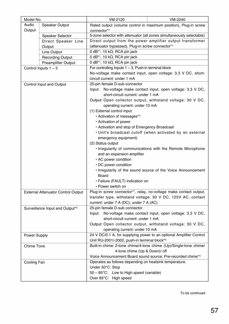
57
To be continued
VM-2120 VM-2240
5-zone selector with attenuator (all zones simultaneously selectable) Direct output from the power amplifier output transformer(attenuator bypassed), Plug-in screw connector*7
0 dB*1, 10 kΩ, RCA pin jack 0 dB*1, 10 kΩ, RCA pin jack 0 dB*1, 10 kΩ, RCA pin jack For controlling Inputs 1 – 3, Push-in terminal block No-voltage make contact input, open voltage: 3.3 V DC, short-circuit current: under 1 mA 25-pin female D-sub connector Input: No-voltage make contact input, open voltage: 3.3 V DC,
short-circuit current: under 1 mA Output: Open collector output, withstand voltage: 30 V DC,
operating current: under 10 mA (1) External control input
• Activation of messages*4
• Activation of power • Activation and stop of Emergency Broadcast • Unit's broadcast cutoff (when activated by an external
emergency equipment) (2) Status output
• Irregularity of communications with the Remote Microphoneand an expansion amplifier
• AC power condition • DC power condition • Irregularity of the sound source of the Voice Announcement
Board • Failure (FAULT) indication on • Power switch on
Plug-in screw connector*7, relay, no-voltage make contact output,transfer type, withstand voltage: 30 V DC, 125V AC, contactcurrent: under 7 A (DC), under 7 A (AC)25-pin female D-sub connectorInput: No-voltage make contact input, open voltage: 3.3 V DC,
short-circuit current: under 1 mA Output: Open collector output, withstand voltage: 30 V DC,
operating current: under 10 mA24 V DC/0.1 A, for supplying power to an optional Amplifier ControlUnit RU-2001/-2002, push-in terminal block*6
Built-in chime: 2-tone chime/4-tone chime (Up)/Single-tone chime/4-tone chime (Up & Down)/ off
Voice Announcement Board sound source: Pre-recorded chime*4
Operates as follows depending on heatsink temperature. Under 50°C: Stop 50 – 85°C: Low to High speed (variable) Over 85°C: High speed
Model No. Speaker Output
Speaker Selector Direct Speaker LineOutputLine Output Recording Output Preamplifier Output
Control Inputs 1 – 3
Control Input and Output
External Attenuator Control Output
Surveillance Input and Output*5
Power Supply
Chime Tone
Cooling Fan
Rated output (volume control in maximum position), Plug-in screwconnector*7
Audio Output
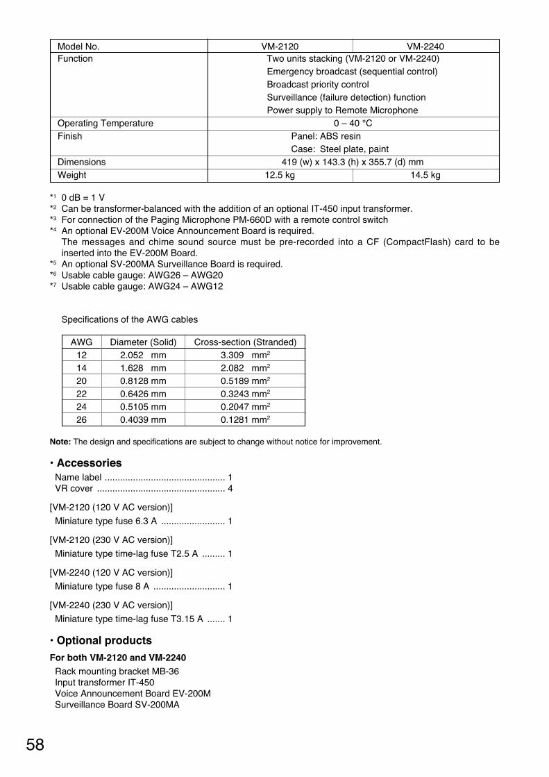
58
*1 0 dB = 1 V *2 Can be transformer-balanced with the addition of an optional IT-450 input transformer. *3 For connection of the Paging Microphone PM-660D with a remote control switch *4 An optional EV-200M Voice Announcement Board is required.
The messages and chime sound source must be pre-recorded into a CF (CompactFlash) card to beinserted into the EV-200M Board.
*5 An optional SV-200MA Surveillance Board is required. *6 Usable cable gauge: AWG26 – AWG20 *7 Usable cable gauge: AWG24 – AWG12
Specifications of the AWG cables
Note: The design and specifications are subject to change without notice for improvement.
• Accessories Name label ............................................... 1 VR cover .................................................. 4
[VM-2120 (120 V AC version)]
Miniature type fuse 6.3 A ......................... 1
[VM-2120 (230 V AC version)]
Miniature type time-lag fuse T2.5 A ......... 1
[VM-2240 (120 V AC version)]
Miniature type fuse 8 A ............................ 1
[VM-2240 (230 V AC version)]
Miniature type time-lag fuse T3.15 A ....... 1
• Optional products
For both VM-2120 and VM-2240 Rack mounting bracket MB-36 Input transformer IT-450 Voice Announcement Board EV-200M Surveillance Board SV-200MA
VM-2120 VM-2240 Two units stacking (VM-2120 or VM-2240) Emergency broadcast (sequential control) Broadcast priority control Surveillance (failure detection) function Power supply to Remote Microphone
0 – 40 °C Panel: ABS resin Case: Steel plate, paint
419 (w) x 143.3 (h) x 355.7 (d) mm12.5 kg 14.5 kg
Model No. Function
Operating Temperature Finish
Dimensions Weight
AWG 121420222426
Diameter (Solid) 2.052 mm 1.628 mm 0.8128 mm 0.6426 mm 0.5105 mm 0.4039 mm
Cross-section (Stranded) 3.309 mm2
2.082 mm2
0.5189 mm2
0.3243 mm2
0.2047 mm2
0.1281 mm2

59
[Remote Microphone Extension RM-210]
20 mA maximum (in terms of RM-200M's DC power input) Connection to RM-200M by dedicated cable Activation of Voice Announcement Board's voice messages whencontrolling speakers in 10 zones at RM-200M ABS resin 110 (w) x 76.5 (h) x 215 (d) mm 350 g
Current Consumption Connection Function
Finish Dimensions Weight
24 V DC (Operating range: 14 – 28 V DC) Power input jack: Non-polarity type Usable power input plug*3: Outer diameter ø5.5 mm, inner diameter
ø2.1 mm, length 9.5 mm 100 mA maximum Under 1% 100 – 20,000 Hz Over 60 dB 0 dB*1, 600 Ω, balanced Unidirectional electret condenser microphone Zones 1 – 5 or Zones 1 – 10 (2 stacked amplifiers connection),Groups 1 – 2, and All-Zone Broadcast Activation of Emergency Broadcast (pre-recorded announcement*2
or live microphone announcement) by Emergency Broadcast Switch Activation of 5 messages*2
Up to 4 RS-485 Control Microphone volume control Category 5 STP cable, RJ45 connector 800 m maximum in total Only a single unit can be power-supplied from VM-2120 or VM-2240 amplifier. Line resistance: Under 40 Ω (one way) ABS resin 190 (w) x 76.5 (h) x 215 (d) mm (Gooseneck microphone excluded) 750 g
Power Source
Current Consumption Distortion Frequency Response Signal-to-Noise Ratio Audio Output Microphone Speaker Control
Emergency Broadcast
Voice Message Control No. of Connectable Units Communication System Volume Control Connection Cable and Connector Communication Distance DC Power Supply from Amplifier
Finish Dimensions Weight
[Remote Microphone RM-200M]
Remarks 120 V AC version
230 V AC version
Part name AD-4800 (US) AD-4800 (ER) AD-4800 (BS) AD-4800 (AS)
Part code 100-07-290-70 100-07-291-80 100-07-292-10 100-07-293-60
*1 0 dB = 1 V*2 An optional EV-200M Board must be mounted in the VM-2120 or VM-2240 Amplifier.
The voice messages must be pre-recorded into a CF (CompactFlash) card to be inserted into the EV-200MBoard.
*3 Suppliable AC adapters
Note: The design and specifications are subject to change without notice for improvement.
• Accessory Link cable (3 m) ....................................... 1
Note: The design and specifications are subject to change without notice for improvement.
• Accessories
Extension cable ....................................... 1 Linkage bracket A .................................... 2
Linkage bracket B .................................... 1 Screw for linkage bracket ...................... 12
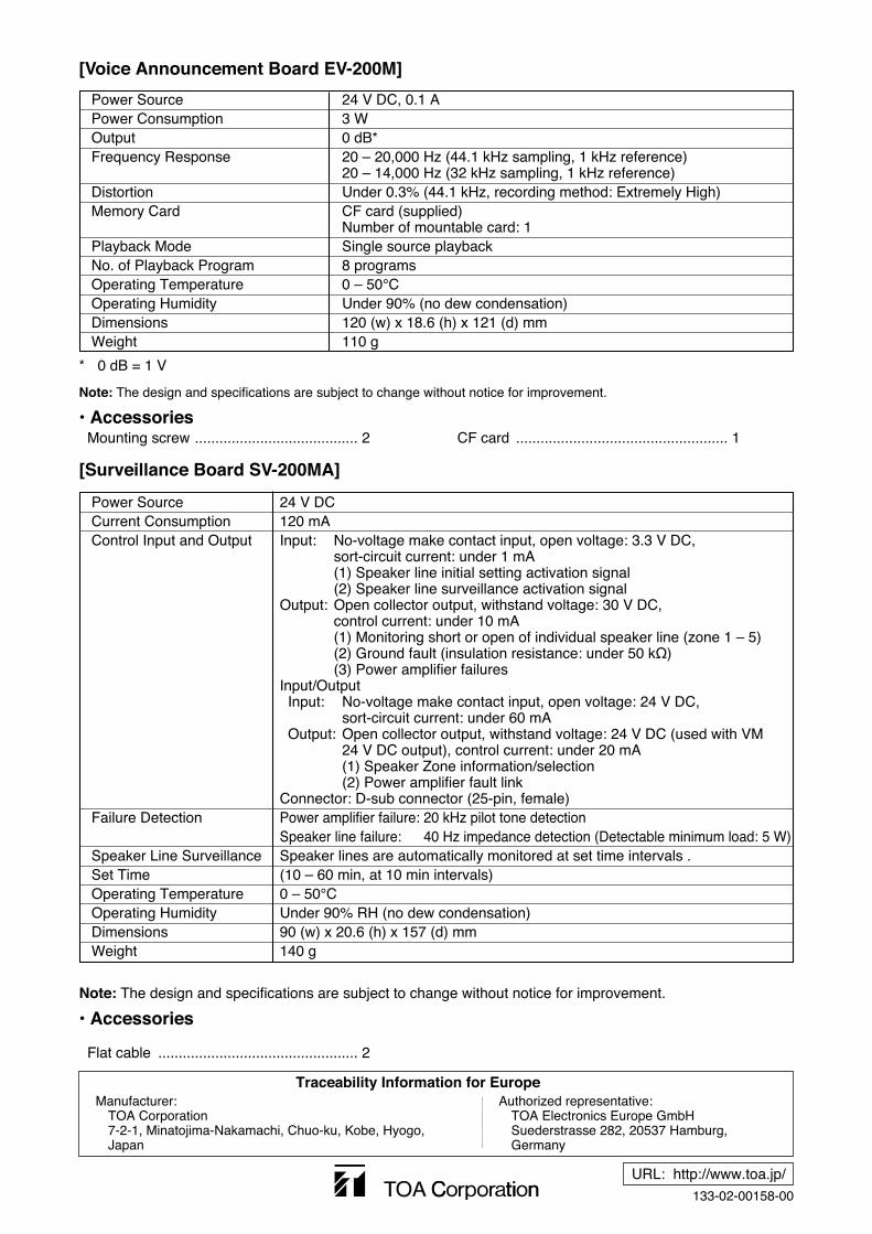
133-02-00158-00
URL: http://www.toa.jp/
Traceability Information for EuropeManufacturer:
TOA Corporation7-2-1, Minatojima-Nakamachi, Chuo-ku, Kobe, Hyogo, Japan
Authorized representative:TOA Electronics Europe GmbHSuederstrasse 282, 20537 Hamburg,Germany
[Voice Announcement Board EV-200M]
24 V DC, 0.1 A 3 W 0 dB* 20 – 20,000 Hz (44.1 kHz sampling, 1 kHz reference) 20 – 14,000 Hz (32 kHz sampling, 1 kHz reference) Under 0.3% (44.1 kHz, recording method: Extremely High) CF card (supplied)Number of mountable card: 1 Single source playback 8 programs 0 – 50°CUnder 90% (no dew condensation)120 (w) x 18.6 (h) x 121 (d) mm 110 g
Power Source Power Consumption Output Frequency Response
Distortion Memory Card
Playback Mode No. of Playback Program Operating Temperature Operating Humidity Dimensions Weight
Mounting screw ........................................ 2 CF card .................................................... 1
* 0 dB = 1 V
Note: The design and specifications are subject to change without notice for improvement.
• Accessories
[Surveillance Board SV-200MA]
24 V DC 120 mA Input: No-voltage make contact input, open voltage: 3.3 V DC,
sort-circuit current: under 1 mA(1) Speaker line initial setting activation signal(2) Speaker line surveillance activation signal
Output: Open collector output, withstand voltage: 30 V DC,control current: under 10 mA(1) Monitoring short or open of individual speaker line (zone 1 – 5)(2) Ground fault (insulation resistance: under 50 kΩ)(3) Power amplifier failures
Input/OutputInput: No-voltage make contact input, open voltage: 24 V DC,
sort-circuit current: under 60 mAOutput: Open collector output, withstand voltage: 24 V DC (used with VM
24 V DC output), control current: under 20 mA(1) Speaker Zone information/selection(2) Power amplifier fault link
Connector: D-sub connector (25-pin, female)Power amplifier failure: 20 kHz pilot tone detectionSpeaker line failure: 40 Hz impedance detection (Detectable minimum load: 5 W)Speaker lines are automatically monitored at set time intervals .(10 – 60 min, at 10 min intervals)0 – 50°CUnder 90% RH (no dew condensation)90 (w) x 20.6 (h) x 157 (d) mm 140 g
Power Source Current Consumption Control Input and Output
Failure Detection
Speaker Line SurveillanceSet Time Operating Temperature Operating Humidity Dimensions Weight
Flat cable ................................................. 2
Note: The design and specifications are subject to change without notice for improvement.
• Accessories


