
V11-T2-8 Volume 11—Vehicle and Commercial Controls CA08100013E—August 2012 www.eaton.com
2
2
2
2
2
2
2
2
2
2
2
2
2
2
2
2
2
2
2
2
2
2
2
2
2
2
2
2
2
2
2.2 Rockers
NGR Rocker Switches
NGR Rocker Switches ContentsDescription Page
NGR Rocker SwitchesSwitch Base . . . . . . . . . . . . . . . . . . . . . . . . . . . V11-T2-10
Rocker Buttons/Actuators . . . . . . . . . . . . . . . . V11-T2-11
Lens Selection . . . . . . . . . . . . . . . . . . . . . . . . . V11-T2-13
NGR Complete Indicators and Indicator Caps . V11-T2-14
NGR Indicator Base and Indicator Caps . . . . . . V11-T2-15
Technical Data and Specifications . . . . . . . . . . V11-T2-16
Standard Circuit Diagrams . . . . . . . . . . . . . . . . V11-T2-17
Dimensions . . . . . . . . . . . . . . . . . . . . . . . . . . . V11-T2-30
Product DescriptionEaton presents its NGR Rocker Switches. This field-proven line of full-sized rocker switches, initially developed for the heavy truck industry, is now found in a variety of vehicle-related applications.
The NGR offers both European styling and ergonomic design while still providing the solid durability that you have come to expect from Eaton switches.
Illuminated and non-illuminated versions with either incandescent bulbs or LEDs are available in either dependent or independent circuits and in a variety of popular switching circuits.
The NGR also offers a variety of rocker buttons and indicators with laser-etched or pad-printed icons, insertable lenses and adhesive-backed labels.
Features● Sealing Standard switch provides splash and dust resistance to IP42. The sealed version is sealed to IP67 when supplied with panel seal.
● Rocker The standard actuator for the NGR is a clean, European-styled, two-face rocker made of high-quality thermoplastic material. The rocker is replaceable and snaps on and off the switch. Both the rocker and the bezel are supplied with an aesthetically pleasing matte finish. Different colors are also available, but black is standard. Rockers can be ordered separately.
● Lighting Each switch is capable of accommodating two incandescent light bulbs or LEDs for lighting purposes. A lamp or LED can be located at either end of the switch and oriented to be circuit dependent or independent. The incandescent bulbs are front replaceable. Two lamp or LED voltages, 14 Vdc and 28 Vdc, are standard. For additional voltages or colors, consult your local Eaton Sales Representative.
Standards and Certifications● Approvable under stringent
UL and CSA standards● For information, contact
your local Eaton Sales Representative
● RoHS Compliant 1
Note1 Visit www.eaton.com/vcbu for
the most up-to-date list of verified part numbers.

Volume 11—Vehicle and Commercial Controls CA08100013E—August 2012 www.eaton.com V11-T2-9
2
2
2
2
2
2
2
2
2
2
2
2
2
2
2
2
2
2
2
2
2
2
2
2
2
2
2
2
2
2
2.2Rockers
NGR Rocker Switches
Options ● Circuits
● 1PST, 1PDT, 2PST and 2PDT
● Maintained and momentary action
● Common lamp ground jumper for dual lamp units
● Multiple LEDs for daylight readability
● Additional colors of rockers, mounting bezels and lenses are available
● Special circuits● Special ratings● Pad-printed legends on
lens, rocker and bezel● Special lamps and lamp
voltages● Dry circuit capabilities● Custom back-lit legends
available● Reversing jumpers
(internal)
● Gang mounting system, see Page V11-T2-77
● Locking rocker with locking feature in UP and/or DOWN positions
● Indicators with laser-etched or insertable lenses, or adhesive labels
● IP67 rated sealed switch● Polarized lock-on
connectors, seePage V11-T2-76● 28-5637-2 for Packard
terminals● 28-5940 for AMP
terminals
● Panel plug 17-21543● Replacement bulb catalog
number ● 14V: 28-5901● 28V: 28-5909
For more information on additional options, contact your local Eaton Sales Representative.
Legends Two legend areas are provided on the ends of each rocker of sufficient size to accommodate two lines consisting of four Helvetica Narrow 12-point characters. Legends may be non-illuminated or illuminated. The NGR offers three styles of illuminated legends.
Single-piece back-lit—Back-lighting is a high-quality automotive/truck industry technique. The legend can appear daylight white or dead-front when non-illuminated but, depending on the back-lit color chosen, will change color when illuminated. Examples of standard back-lit legends are found on Pages V11-T2-80 to V11-T2-94.
Snap-in lenses—This rocker will have either one or two snap-in lenses in the legend areas. Legends are typically pad-printed on the lens in black or white. Snap-in lenses are available in six standard colors and can be ordered separately.
Label rocker—This rocker has a one-piece adhesive-backed label inserted into a recessed area on the face of the button. Legends can be done in several colors and be illuminated or non-illuminated. Contact your local Eaton Sales Representative for suggested sources.
Flexible Ordering SystemYou can order assembled switches or the switch base and actuator separately.
Use the final code in the switch base catalog number, Page V11-T2-10, to denote assembly instructions.

V11-T2-10 Volume 11—Vehicle and Commercial Controls CA08100013E—August 2012 www.eaton.com
2
2
2
2
2
2
2
2
2
2
2
2
2
2
2
2
2
2
2
2
2
2
2
2
2
2
2
2
2
2
2.2 Rockers
NGR Rocker Switches
Switch Base
To order rocker and switch base assembled, contact your local Eaton Sales Representative. To order rocker buttons, see Page V11-T2-11. To order lenses, see Page V11-T2-13. To order indicator caps, see Page V11-T2-15. For a complete indicator, see Page V11-T2-14.
Catalog Number Selection How To Order—Switch Base
Notes1 Circuits show lighting options available. See Pages V11-T2-17 to V11-T2-29. 2 Locks in DOWN position.3 Locks in UP and DOWN positions.4 Locks in UP position.5 Switch contact construction plating—
N = Standard: Recommended for use on loads up to 12 amps at 14 Vdc.T = High Rated: Recommended for use on loads greater than 12 amps at 14 Vdc.G = Gold: Recommended for use on dry circuit/low level switching.
6 Replaceable.7 Replaceable/wedge base LED.8 PCB version LED.
Rocker and Paddle Frame
Full Palm Guard Panel Seal and Internal Seal
To determine complete catalog number, start with the appropriate base prefix and add the appropriate code letters and/or numbers.
N G R 1 5 0 1 4 B N A 0 NSwitch Series
(Unsealed)NGR = Switch base
Circuit 1
1501 = CircuitSee Pages V11-T2-17 to V11-T2-29.
Frame Style1 = Rocker and paddle
frame2 = Palm guard (top)3 = Palm guard (bottom)4 = Full palm guard
(top/bottom)S = Panel seal and
internal sealG = Locking rocker 2
D = Locking rocker 3
F = Locking rocker 4
T = Internal seal
“A” LampType and Color
0 = No lampA = 14 Vdc incand./clear 6
B = 24 Vdc incand./clear 6
C = 28V LED/red 8
D = 28V LED/green 8
E = 28V LED/amber 8
R = 14V LED/redG = 14V LED/greenY = 14V LED/amberK = 28V LED/red 7
L = 28V LED/green 7
T = 28V LED/amber 7
W = 28V LED/white 7
X = 28V LED/blue 7
H = 14V LED/high intensity redJ = 14V LED/high intensity greenP = 14V LED/high intensity amber
M = 14V LED/high intensity blue
Example:
Switch Contact Plating 5
N = StandardT = High ratedG = Gold
Rocker Assembled
N = No
Frame Color
B = Black
“B” LampType and Color
0 = No lampA = 14 Vdc incand./clear 6
B = 24 Vdc incand./clear 6
C = 28V LED/red 8
D = 28V LED/green 8
E = 28V LED/amber 8
R = 14V LED/redG = 14V LED/greenY = 14V LED/amberK = 28V LED/red 7
L = 28V LED/green 7
T = 28V LED/amber 7
W = 28V LED/white 7
X = 28V LED/blue 7
H = 14V LED/high intensity redJ = 14V LED/high intensity greenP = 14V LED/high intensity amber
M = 14V LED/high intensity blue

Volume 11—Vehicle and Commercial Controls CA08100013E—August 2012 www.eaton.com V11-T2-11
2
2
2
2
2
2
2
2
2
2
2
2
2
2
2
2
2
2
2
2
2
2
2
2
2
2
2
2
2
2
2.2Rockers
NGR Rocker Switches
Rocker Buttons/Actuators
Catalog Number SelectionHow To Order—Rocker Buttons/Actuators
Notes1 Decorative rocker only.2 Two-face rocker only.
Two-Face Rocker, No Lens
Decorative Rocker, Back-Lit
Decorative Paddle, Back-Lit
Two-Face Rocker, Snap-In Lens
Locking Rocker
Label Rocker
Icon “A” Lighted Color or Lens Color
A = RedB = GreenC = AmberE = BlueF = WhiteG = Clear0 = Non-lighted or no lens
Icon “A” OrientationA = Standard orientationB = 90° clockwise C = 180° clockwiseD = 270° clockwise 0 = No icon; no orientation
Icon “A” CodeAF = UnlockSee Symbols Library on Pages V11-T2-80 to V11-T2-94.
Icon “A” Color0 = No icon; no color1 = Daylight white 12 = Deadfront 13 = White 24 = Black 25 = Lens hole (no lens)
Icon/Lens/Hole LocationA = “A” onlyB = “B” onlyC = “A” and “B”D = No icon/lens/hole
To determine complete catalog number, start with the appropriate button type and add the appropriate code letters and/or numbers.
3 C A F A 1 B A E C 4 A 3
Rocker Button Type1 = Two-face, no lens rocker2 = Two-face, snap-in lens rocker3 = Decorative rocker, back-lit4 = Decorative paddle, back-lit5 = Locking rocker6 = Label rocker
Example:
Indicator Stripe Location
1 = “A” Position2 = “B” Position3 = “A” and “B” Positions0 = No stripe
Icon “B” Lighted Color or Lens Color
A = RedB = GreenC = AmberE = BlueF = WhiteG = Clear0 = Non-lighted or no lens
Icon “B” OrientationA = Standard orientationB = 90° clockwise C = 180° clockwiseD = 270° clockwise 0 = No icon; no orientation
Icon “B” CodeAE = LockSee Symbols Library on Pages V11-T2-80 to V11-T2-94.
Icon “B” Color0 = No icon; no color1 = Daylight white 12 = Deadfront 13 = White 24 = Black 25 = Lens hole (no lens)

V11-T2-12 Volume 11—Vehicle and Commercial Controls CA08100013E—August 2012 www.eaton.com
2
2
2
2
2
2
2
2
2
2
2
2
2
2
2
2
2
2
2
2
2
2
2
2
2
2
2
2
2
2
2.2 Rockers
NGR Rocker Switches
Icon Location Examples Location A
Location B
Location C
Icon Orientation Examples Orientation A
Orientation B
Orientation C
Orientation D
Rocker with Icon in “A” Position (Code A)
Rocker with Icon in “B” Position (Code B)
Rocker with Icon in “C” Position (Code C)
Rocker with Standard Orientation (Code A)
Rocker with Icon at 90° Clockwise (Code B)
Rocker with Icon at 180° Clockwise (Code C)
Rocker with Icon at 270° Clockwise (Code D)

Volume 11—Vehicle and Commercial Controls CA08100013E—August 2012 www.eaton.com V11-T2-13
2
2
2
2
2
2
2
2
2
2
2
2
2
2
2
2
2
2
2
2
2
2
2
2
2
2
2
2
2
2
2.2Rockers
NGR Rocker Switches
Lens Selection For NGR Rocker Type “2” and Indicator Type “2CAP” only.
Catalog Number Selection How To Order—Translucent Lenses 12
How To Order—Transparent Lenses 12
Notes1 When ordering a lens with an icon for the code B (bottom) position, specify code C orientation. 2 Standard lens type.3 Non-standard lens type.4 Standard pad print for white and clear lens is black.
Translucent Lens Transparent Lens
To determine complete catalog number, start with the appropriate base prefix and add the appropriate code letters and/or numbers.
2 8 - 5 8 6 3 - 2 A F ABase
Catalog Number28-5863-2 28-586328-5863-328-5863-928-5863-8
Example:
Orientation Style CodeA = Standard orientationB = Rotated 90° clockwise C = Inverted 180°D = Rotated 270° clockwise
Icon CodeAF = UnlockSee Symbols Library on Pages V11-T2-80 to V11-T2-94.
LensColor
RedGreenAmberBlueWhite 4
To determine complete catalog number, start with the appropriate base prefix and add the appropriate code letters and/or numbers.
2 8 - 5 8 6 3 - 5 A F ABase
Catalog Number28-5863-5 28-5863-428-5863-628-5863-1028-5863-7
Example:
Orientation Style CodeA = Standard orientationB = Rotated 90° clockwise C = Inverted 180°D = Rotated 270° clockwise
Icon CodeAF = UnlockSee Symbols Library on Pages V11-T2-80 to V11-T2-94.
LensColor
RedGreenAmberBlueClear 4

V11-T2-14 Volume 11—Vehicle and Commercial Controls CA08100013E—August 2012 www.eaton.com
2
2
2
2
2
2
2
2
2
2
2
2
2
2
2
2
2
2
2
2
2
2
2
2
2
2
2
2
2
2
2.2 Rockers
NGR Rocker Switches
NGR Complete Indicators and Indicator CapsTo order rocker buttons, see Page V11-T2-11. To order lenses, see Page V11-T2-13.
Catalog Number SelectionHow To Order—Complete Indicator
Notes1 Decorative rocker only.2 Two-face rocker only.
Complete Indicator and Indicator Cap Assembled
Icon “A” Lighted Color or Lens Color
A = RedB = GreenC = AmberE = BlueF = WhiteG = Clear0 = Non-lighted or no lens
Lamp/LED Type and ColorA = 14 Vdc incand./clearB = 28 Vdc incand./clear0 = No lamp/LEDR = 14V LED/redG = 14V LED/greenY = 14V LED/amberK = 28V LED/redL = 28V LED/greenT = 28V LED/amberH = 14V LED/high intensity redJ = 14V LED/high intensity greenP = 14V LED/high intensity amber
M = 14V LED/high intensity blue
To determine complete catalog number, start with the appropriate indicator type and add the appropriate code letters and/or numbers.
2 N C A A R 1 B A B A 0 A
Indicator Type2N = Two-face, snap-in lens3N = Laser-etched6N = Label
Example:
Icon “A” CodeAA = HornSee Symbols Library on PagesV11-T2-80 to V11-T2-94.
Icon “A” Color0 = No icon; no color1 = Daylight white 12 = Deadfront 13 = White 24 = Black 25 = Lens hole (no lens)
Icon/Lens/Hole LocationA = “A” icon onlyB = “B” icon onlyC = “A” and “B” iconsD = No icon/lens/hole
Icon “B” Lighted Color or Lens Color
A = RedB = GreenC = AmberE = BlueF = WhiteG = Clear0 = Non-lighted or no lens
Lamp/LED Type and ColorA = 14 Vdc incand./clearB = 28 Vdc incand./clear0 = No lamp/LEDR = 14V LED/redG = 14V LED/greenY = 14V LED/amberK = 28V LED/redL = 28V LED/greenT = 28V LED/amberH = 14V LED/high intensity redJ = 14V LED/high intensity greenP = 14V LED/high intensity amber
M = 14V LED/high intensity blue
Icon “B” CodeAB = BatterySee Symbols Library on PagesV11-T2-80 to V11-T2-94.
Icon “B” Color0 = No icon; no color1 = Daylight white 12 = Deadfront 13 = White 24 = Black 25 = Lens hole (no lens)

Volume 11—Vehicle and Commercial Controls CA08100013E—August 2012 www.eaton.com V11-T2-15
2
2
2
2
2
2
2
2
2
2
2
2
2
2
2
2
2
2
2
2
2
2
2
2
2
2
2
2
2
2
2.2Rockers
NGR Rocker Switches
NGR Indicator Base and Indicator CapsTo order rocker buttons, see Page V11-T2-11. To order lenses, see Page V11-T2-13. To order complete indicator, see Page V11-T2-14.
Catalog Number SelectionHow To Order—Indicator Base
How To Order—Indicator Cap
Notes1 Decorative rocker only.2 Two-face rocker only.
Indicator Base Indicator Cap
To determine complete catalog number, start with the appropriate base prefix and add the appropriate code letters and/or numbers.
N G R I N D A 0 N
Switch Series (Unsealed) NGRIND = Indicator base
“A” Lamp Type and Color
0 = No lampA = 14 Vdc incand./clearB = 24 Vdc incand./clearR = 14V LED/redG = 14V LED/greenY = 14V LED/amberK = 28V LED/redL = 28V LED/greenT = 28V LED/amberX = 28V LED/blueH = 14V LED/high intensity redJ = 14V LED/high intensity greenP = 14V LED/high intensity amber
M = 14V LED/high intensity blue
Example:
Rocker Assembled
N = No
“B” Lamp Type and Color
0 = No lampA = 14 Vdc incand./clearB = 24 Vdc incand./clearR = 14V LED/redG = 14V LED/greenY = 14V LED/amberK = 28V LED/redL = 28V LED/greenT = 28V LED/amberX = 28V LED/blueH = 14V LED/high intensity redJ = 14V LED/high intensity greenP = 14V LED/high intensity amber
M = 14V LED/high intensity blue
2 C A P C A B 1 B A H 0 A
Icon/Lens/Hole LocationA = “A” icon onlyB = “B” icon onlyC = “A” and “B” iconsD = No icon/lens/hole
To determine complete catalog number, start with the appropriate indicator type and add the appropriate code letters and/or numbers.
Indicator Type2CAP = Two-face,
snap-in lens3CAP = Decorative/
laser-etched6CAP = Label
Example:
Icon “A” CodeAB = BatterySee Symbols Library on PagesV11-T2-80 to V11-T2-94.
Icon “A” Color0 = No icon; no color1 = Daylight white 12 = Deadfront 13 = White 24 = Black 25 = Lens hole (no lens)
Icon “B” CodeAH = FuelSee Symbols Library on PagesV11-T2-80 to V11-T2-94.
Icon “B” Color0 = No icon; no color1 = Daylight white 12 = Deadfront 13 = White 24 = Black 25 = Lens hole (no lens)
Icon “B” Lighted Color or Lens Color
A = RedB = GreenC = Amber
E = BlueF = WhiteG = Clear
0 = Non-lighted or no lens
Icon “A” Lighted Color or Lens Color
A = RedB = GreenC = Amber
E = BlueF = WhiteG = Clear
0 = Non-lighted or no lens

V11-T2-16 Volume 11—Vehicle and Commercial Controls CA08100013E—August 2012 www.eaton.com
2
2
2
2
2
2
2
2
2
2
2
2
2
2
2
2
2
2
2
2
2
2
2
2
2
2
2
2
2
2
2.2 Rockers
NGR Rocker Switches
Technical Data and Specifications
NGR Rocker Switches
Notes1 For information, contact your local Eaton Sales Representative. 2 Best results obtained between 0.060 and 0.118 in (1.5 and 3.0 mm). 3 On sealed versions, recommended panel thickness between 0.079 and 0.118 in (2.0 and 3.0 mm).
Description Specification
Ratings 1 15A at 125 Vac, 10A at 250 Vac15A at 28 Vdc (14 Vdc rating)Approvable under stringent UL and CSA standards
Contact mechanism Slow-make/slow-break contact mechanismButt action contact mechanism designed specifically for use on AC and low voltage DC applications
Contact material— Standard construction
Movable—copper alloy with silver alloy contact face buttonStationary—silver-plated copper alloy with silver alloy contact face button
Mechanical life 250,000 operations, minimum
Electrical life 200,000 operations, minimum
Terminal type Standard 0.25 in (6.35 mm) spade, silver-plated copper alloy
Base material High-grade thermoplastic molding material
Dielectric 1000V rms, minimum
Mounting means Snap-in mounting with plastic bezel
Mounting hole Rectangular panel cutout 1.734 x 0.867 in (44 x 22 mm)
Panel thickness 0.040 to 0.156 in (1.0 to 4.0 mm) 2 3
IP rating Standard IP42; sealed option IP67
Operating temperature range
–40° to 185°F (–40° to 85°C)

Volume 11—Vehicle and Commercial Controls CA08100013E—August 2012 www.eaton.com V11-T2-17
2
2
2
2
2
2
2
2
2
2
2
2
2
2
2
2
2
2
2
2
2
2
2
2
2
2
2
2
2
2
2.2Rockers
NGR Rocker Switches
Standard Circuit DiagramsSingle-Pole Two-Pole
Circuit with Rocker In …
Circuit No.Schematic(Shown in UP Position)
DOWN Position
CENTER Position
UP Position
1001 OFF NONE ON
— — 2B-3
1501 OFF NONE ON
— — 2B-3-9
1502 OFF NONE ON
— — 2B-3-10
1503 OFF NONE ON
— — 2B-3
1504 OFF NONE ON
— — 2B-3
1505 OFF NONE ON
— — 2B-3-9
1506 OFF NONE ON
— — 2B-3-10
1507 OFF NONE ON
— — 2B-3-9-10
1508 OFF NONE ON
— — 2B-3
109
4
8
5B
613
2B
7
109
4
8
5B
613
2B
7
5B
10
461
8
2B
9
3
7
10
461
8
5B
9
3
7
2B
10
4
8
5B
61
9
3
2B
7
4
10
5B
1 63
9
2B
87
9
3
7
2B 5B
61
10
4
8
2B
7 8
5B
3
9
4
10
1 6
4
10
5B
1 6
8
3
9
2B
7
Circuit with Rocker In …
Circuit No.Schematic(Shown in UP Position)
DOWN Position
CENTER Position
UP Position
2001 OFF NONE ON
— — 2B-35B-6
2501 OFF NONE ON
— — 2B-3-95B-6
2502 OFF NONE ON
— — 2B-3-105B-6
2503 OFF NONE ON
— — 2B-35B-6
2504 OFF NONE ON
— — 2B-35B-6
2505 OFF NONE ON
— — 2B-3-95B-6
2506 OFF NONE ON
— — 2B-3-105B-6
2507 OFF NONE ON
— — 2B-3-9-15B-6
2508 OFF NONE ON
— — 2B-35B-6
10
5B
4
8
6
9
2B
13
7
10
46
5B
8
1
9
3
2B
7
13
9 10
46
2B
7 8
5B
109
5B
46
8
2B
13
7
109
5B
4
8
6
2B
13
7
10
461
9
3
5B
8
2B
7
10
461
9
3
5B
8
2B
7
2B 5B
10
46
9
13
87
7 8
10
5B
46
9
2B
13

V11-T2-18 Volume 11—Vehicle and Commercial Controls CA08100013E—August 2012 www.eaton.com
2
2
2
2
2
2
2
2
2
2
2
2
2
2
2
2
2
2
2
2
2
2
2
2
2
2
2
2
2
2
2.2 Rockers
NGR Rocker Switches
Single-Pole Two-Pole
Circuit with Rocker In …
Circuit No.Schematic(Shown in UP Position)
DOWN Position
CENTER Position
UP Position
1002 OFF NONE MOM. ON
— — 2B-3
1521 OFF NONE MOM. ON
— — 2B-3-9
1522 OFF NONE MOM. ON
— — 2B-3-10
1523 OFF NONE MOM. ON
— — 2B-3
1524 OFF NONE MOM. ON
— — 2B-3
1525 OFF NONE MOM. ON
— — 2B-3-9
1526 OFF NONE MOM. ON
— — 2B-3-10
1528 OFF NONE MOM. ON
— — 2B-3
10
5B
4
8
6
9
2B
13
7
10
46
5B
8
1
9
3
2B
7
10
46
5B
8
1
9
3
2B
7
109
5B
46
8
2B
13
7
109
5B
4
8
6
2B
13
7
10
461
9
3
5B
8
2B
7
10
461
9
3
5B
8
2B
7
7 8
10
5B
46
9
2B
13
Circuit with Rocker In …
Circuit No.Schematic(Shown in UP Position)
DOWN Position
CENTER Position
UP Position
2002 OFF NONE MOM. ON
— — 2B-35B-6
2521 OFF NONE MOM. ON
— — 2B-3-95B-6
2522 OFF NONE MOM. ON
— — 2B-3-105B-6
2523 OFF NONE MOM. ON
— — 2B-35B-6
2524 OFF NONE MOM. ON
— — 2B-35B-6
2525 OFF NONE MOM. ON
— — 2B-3-95B-6
2526 OFF NONE MOM. ON
— — 2B-3-105B-6
2528 OFF NONE MOM. ON
— — 2B-35B-6
5B
10
4
8
2B
61
9
3
7
5B
10
4
8
2B
61
9
3
7
5B
10
4
8
2B
61
9
3
7
109
5B
4
8
2B
613
7
5B
10
4
8
9
2B
613
7
10
461
9
3
5B
8
2B
7
5B
10
4
8
61
9
3
2B
7
5B
8
10
4
7
2B
61
9
3

Volume 11—Vehicle and Commercial Controls CA08100013E—August 2012 www.eaton.com V11-T2-19
2
2
2
2
2
2
2
2
2
2
2
2
2
2
2
2
2
2
2
2
2
2
2
2
2
2
2
2
2
2
2.2Rockers
NGR Rocker Switches
Single-Pole Two-Pole
Circuit with Rocker In …
Circuit No.Schematic(Shown in UP Position)
DOWN Position
CENTER Position
UP Position
1003 ON NONE ON
2B-1 — 2B-3
1541 ON NONE ON
2B-1 — 2B-3-9
1542 ON NONE ON
2B-1 — 2B-3-10
1543 ON NONE ON
2B-1 — 2B-3
1544 ON NONE ON
2B-1 — 2B-3
1545 ON NONE ON
2B-1 — 2B-3-9
1546 ON NONE ON
2B-1 — 2B-3-10
1547 ON NONE ON
2B-1-10 — 2B-3-9
1548 ON NONE ON
2B-1 — 2B-3
9
7
10
13
2B
6 4
5B
8
10
5B
4
8
2B
1 63
9
7
4
10
1 63
8
5B2B
9
7
2B 5B
10
41 63
8
9
7
4
10
8
5B
3 1 6
2B
9
7
10
4
8
5B
613
2B
9
7
3 1 6 4
10
8
5B2B
9
7
10
41 63
8
5B2B
9
7
8
10
4
5B
61
2B
3
7
9
Circuit with Rocker In …
Circuit No.Schematic(Shown in UP Position)
DOWN Position
CENTER Position
UP Position
2003 ON NONE ON
2B-15B-4
— 2B-35B-6
2541 ON NONE ON
2B-15B-4
— 2B-3-95B-6
2542 ON NONE ON
2B-15B-4
— 2B-3-105B-6
2543 ON NONE ON
2B-15B-4
— 2B-35B-6
2544 ON NONE ON
2B-15B-4
— 2B-35B-6
2545 ON NONE ON
2B-15B-4
— 2B-3-95B-6
2546 ON NONE ON
2B-15B-4
— 2B-3-105B-6
2547 ON NONE ON
2B-1-105B-4
— 2B-3-95B-6
2548 ON NONE ON
2B-15B-4
— 2B-35B-6
109
7
2B
3 1 6 4
5B
8
10
5B
46
8
9
2B
13
7
4
10
613
9
5B
8
2B
7
5B
10
46
8
2B
9
13
7
5B
8
4
10
611
2B
7
3
9
9 10
46
5B
8
13
2B
7
6 4
10
5B
8
3 1
9
2B
7
10
46
5B
8
9
13
2B
7
8
10
5B
46
7
9
2B
13

V11-T2-20 Volume 11—Vehicle and Commercial Controls CA08100013E—August 2012 www.eaton.com
2
2
2
2
2
2
2
2
2
2
2
2
2
2
2
2
2
2
2
2
2
2
2
2
2
2
2
2
2
2
2.2 Rockers
NGR Rocker Switches
Single-Pole Two-Pole
Circuit with Rocker In …
Circuit No.Schematic(Shown in UP Position)
DOWN Position
CENTER Position
UP Position
1004 ON OFF ON
2B-1 — 2B-3
1561 ON OFF ON
2B-1 — 2B-3-9
1562 ON OFF ON
2B-1 — 2B-3-10
1563 ON OFF ON
2B-1 — 2B-3
1564 ON OFF ON
2B-1 — 2B-3
1565 ON OFF ON
2B-1 — 2B-3-9
1566 ON OFF ON
2B-1 — 2B-3-10
1567 ON OFF ON
2B-1-10 — 2B-3-9
1568 ON OFF ON
2B-1 — 2B-3
5B
4
10
8
2B
613
9
7
4
10
8
5B
613
2B
9
7
10
4
8
5B
61
2B
3
9
7
5B2B
4
10
613
8
9
7
4
10
613
8
5B2B
9
7
10
4
8
5B
1 6
2B
3
9
7
4
10
5B
8
61
2B
3
9
7
4
10
8
5B
613
2B
9
7
10
4
8
5B
1 63
2B
9
7
Circuit with Rocker In …
Circuit No.Schematic(Shown in UP Position)
DOWN Position
CENTER Position
UP Position
2004 ON OFF ON
2B-15B-4
— 2B-35B-6
2561 ON OFF ON
2B-15B-4
— 2B-3-95B-6
2562 ON OFF ON
2B-15B-4
— 2B-3-105B-6
2563 ON OFF ON
2B-15B-4
— 2B-35B-6
2564 ON OFF ON
2B-15B-4
— 2B-35B-6
2565 ON OFF ON
2B-15B-4
— 2B-3-95B-6
2566 ON OFF ON
2B-15B-4
— 2B-3-105B-6
2567 ON OFF ON
2B-1-105B-4
— 2B-3-95B-6
2568 ON OFF ON
2B-15B-4
— 2B-35B-6
5B
10
46
8
2B
1
9
3
7
4
10
6
5B
8
13
9
2B
7
10
5B
8
46
9
2B
1
7
3
2B 5B
4
10
613
9
87
10
46
5B
8
1
9
3
2B
7
10
5B
8
46
9
2B
1
7
3
5B
10
46
8
2B
1
9
3
7
4
10
6
5B
8
13
9
2B
7
10
5B
4
8
6
9
2B
13
7

Volume 11—Vehicle and Commercial Controls CA08100013E—August 2012 www.eaton.com V11-T2-21
2
2
2
2
2
2
2
2
2
2
2
2
2
2
2
2
2
2
2
2
2
2
2
2
2
2
2
2
2
2
2.2Rockers
NGR Rocker Switches
Single-Pole Two-Pole
Circuit with Rocker In …
Circuit No.Schematic(Shown in UP Position)
DOWN Position
CENTER Position
UP Position
1005 MOM. ON OFF MOM. ON
2B-1 — 2B-3
1581 MOM. ON OFF MOM. ON
2B-1 — 2B-3-9
1582 MOM. ON OFF MOM. ON
2B-1 — 2B-3-10
1583 MOM. ON OFF MOM. ON
2B-1 — 2B-3
1584 MOM. ON OFF MOM. ON
2B-1 — 2B-3
1585 MOM. ON OFF MOM. ON
2B-1 — 2B-3-9
1586 MOM. ON OFF MOM. ON
2B-1 — 2B-3-10
1587 MOM. ON OFF MOM. ON
2B-1-10 — 2B-3-9
1588 MOM. ON OFF MOM. ON
2B-1 — 2B-3
6
10
8
4
5B
1
2B
3
9
7
6
8
10
4
5B
7
13
2B
9
6
10
413
9
8
5B2B
7
6 4
10
8
5B
3
9
1
2B
7
9 10
6
8
4
5B
13
2B
7
6
10
4
8
5B
13
2B
9
7
6 4
10
8
5B
13
2B
9
7
6
10
8
4
5B
13
2B
9
7
6
10
4
8
5B
13
9
2B
7
Circuit with Rocker In …
Circuit No.Schematic(Shown in UP Position)
DOWN Position
CENTER Position
UP Position
2005 MOM. ON OFF MOM. ON
2B-15B-4
— 2B-35B-6
2581 MOM. ON OFF MOM. ON
2B-15B-4
— 2B-3-95B-6
2582 MOM. ON OFF MOM. ON
2B-15B-4
— 2B-3-105B-6
2583 MOM. ON OFF MOM. ON
2B-15B-4
— 2B-35B-6
2584 MOM. ON OFF MOM. ON
2B-15B-4
— 2B-35B-6
2585 MOM. ON OFF MOM. ON
2B-15B-4
— 2B-3-95B-6
2586 MOM. ON OFF MOM. ON
2B-15B-4
— 2B-3-105B-6
2587 MOM. ON OFF MOM. ON
2B-1-105B-4
— 2B-3-95B-6
2588 MOM. ON OFF MOM. ON
2B-15B-4
— 2B-35B-6
10
4
8
5B
6
9
2B
13
7
7 8
4
10
5B
6
2B
13
9
10
461
9
3
8
5B2B
7
3 4
109
8
5B
6
2B
1
7
9 10
8
4
5B
6
7
2B
13
10
46
8
5B
1
9
3
2B
7
46
10
8
5B
13
9
2B
7
10
4
8
5B
6
9
2B
13
7
10
461
9
3
8
5B2B
7
V11-T2-22 Volume 11—Vehicle and Commercial Controls CA08100013E—August 2012 www.eaton.com
2
2
2
2
2
2
2
2
2
2
2
2
2
2
2
2
2
2
2
2
2
2
2
2
2
2
2
2
2
2
2.2 Rockers
NGR Rocker Switches
Single-Pole Two-Pole
Circuit with Rocker In …
Circuit No.Schematic(Shown in UP Position)
DOWN Position
CENTER Position
UP Position
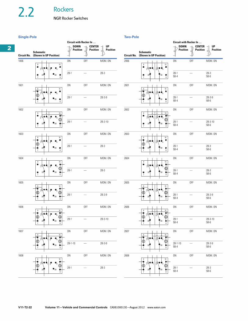
1006 ON OFF MOM. ON
2B-1 — 2B-3
1601 ON OFF MOM. ON
2B-1 — 2B-3-9
1602 ON OFF MOM. ON
2B-1 — 2B-3-10
1603 ON OFF MOM. ON
2B-1 — 2B-3
1604 ON OFF MOM. ON
2B-1 — 2B-3
1605 ON OFF MOM. ON
2B-1 — 2B-3-9
1606 ON OFF MOM. ON
2B-1 — 2B-3-10
1607 ON OFF MOM. ON
2B-1-10 — 2B-3-9
1608 ON OFF MOM. ON
2B-1 — 2B-3
10
4
8
5B
1 63
2B
9
7
8
4
10
5B
1 6
2B
3
7
9
4
10
1 63
9
8
5B2B
7
3 4
10
8
5B
1 6
2B
9
7
10
8
4
5B
1 6
2B
3
9
7
4
10
8
5B
613
2B
9
7
4
10
8
5B
3 1 6
2B
9
7
10
4
8
5B
1 6
2B
3
9
7
4
10
613
8
5B2B
9
7
Circuit with Rocker In …
Circuit No.Schematic(Shown in UP Position)
DOWN Position
CENTER Position
UP Position
2006 ON OFF MOM. ON
2B-15B-4
— 2B-35B-6
2601 ON OFF MOM. ON
2B-15B-4
— 2B-3-95B-6
2602 ON OFF MOM. ON
2B-15B-4
— 2B-3-105B-6
2603 ON OFF MOM. ON
2B-15B-4
— 2B-35B-6
2604 ON OFF MOM. ON
2B-15B-4
— 2B-35B-6
2605 ON OFF MOM. ON
2B-15B-4
— 2B-3-95B-6
2606 ON OFF MOM. ON
2B-15B-4
— 2B-3-105B-6
2607 ON OFF MOM. ON
2B-1-105B-4
— 2B-3-95B-6
2608 ON OFF MOM. ON
2B-15B-4
— 2B-35B-6
10
5B
8
46
9
2B
1
7
3
8
5B
10
46
7
2B
1
9
3
4
10
613
9
5B
8
2B
7
4
10
5B
8
63
9
2B
1
7
10
8
5B
46
9
7
2B
13
4
10
6
5B
8
13
9
2B
7
6 4
10
5B
8
3 1
9
2B
7
10
5B
8
46
9
2B
1
7
3
4
10
6
5B
8
13
9
2B
7

Volume 11—Vehicle and Commercial Controls CA08100013E—August 2012 www.eaton.com V11-T2-23
2
2
2
2
2
2
2
2
2
2
2
2
2
2
2
2
2
2
2
2
2
2
2
2
2
2
2
2
2
2
2.2Rockers
NGR Rocker Switches
Single-Pole Two-Pole
Circuit with Rocker In …
Circuit No.Schematic(Shown in UP Position)
DOWN Position
CENTER Position
UP Position
1007 ON NONE MOM ON
2B-1 — 2B-3
1621 ON NONE MOM ON
2B-1 — 2B-3-9
1622 ON NONE MOM ON
2B-1 — 2B-3-10
1623 ON NONE MOM ON
2B-1 — 2B-3
1624 ON NONE MOM ON
2B-1 — 2B-3
1625 ON NONE MOM ON
2B-1 — 2B-3-9
1626 ON NONE MOM ON
2B-1 — 2B-3-10
1627 ON NONE MOM ON
2B-1-10 — 2B-3-9
1628 ON NONE MOM ON
2B-1 — 2B-3
13 46
7 8
9 10
2B 5B
13 46
7 8
9 10
2B 5B
13 46
7 8
9 10
2B5B
13 46
7 8
9 10
2B 5B
13 46
7 8
9 10
2B 5B
13 46
7 8
9 10
2B 5B
13 46
7 8
9 10
2B 5B
13 46
7 8
9
2B 5B
13 46
7 8
9 10
2B 5B
Circuit with Rocker In …
Circuit No.Schematic(Shown in UP Position)
DOWN Position
CENTER Position
UP Position
2007 ON NONE MOM ON
2B-15B-4
— 2B-35B-6
2621 ON NONE MOM ON
2B-15B-4
— 2B-3-95B-6
2622 ON NONE MOM ON
2B-15B-4
— 2B-3-105B-6
2623 ON NONE MOM ON
2B-15B-4
— 2B-35B-6
2624 ON NONE MOM ON
2B-15B-4
— 2B-35B-6
2625 ON NONE MOM ON
2B-15B-4
— 2B-3-95B-6
2626 ON NONE MOM ON
2B-15B-4
— 2B-3-105B-6
2627 ON NONE MOM ON
2B-1-105B-4
— 2B-3-95B-6
2628 ON NONE MOM ON
2B-15B-4
— 2B-35B-6
13 46
7 8
9 10
2B 5B
13 46
7 8
9 10
2B 5B
13 46
7 8
9 10
2B 5B
13 46
7 8
9 10
2B 5B
13 46
7 8
9 10
2B 5B
13 46
7 8
9 10
2B 5B
13 46
7 8
9 10
2B 5B
13 46
7 8
9 10
2B 5B
13 46
7 8
9 10
2B 5B
V11-T2-24 Volume 11—Vehicle and Commercial Controls CA08100013E—August 2012 www.eaton.com
2
2
2
2
2
2
2
2
2
2
2
2
2
2
2
2
2
2
2
2
2
2
2
2
2
2
2
2
2
2
2.2 Rockers
NGR Rocker Switches
Single-Pole Two-Pole
Circuit with Rocker In …
Circuit No.Schematic(Shown in UP Position)
DOWN Position
CENTER Position
UP Position
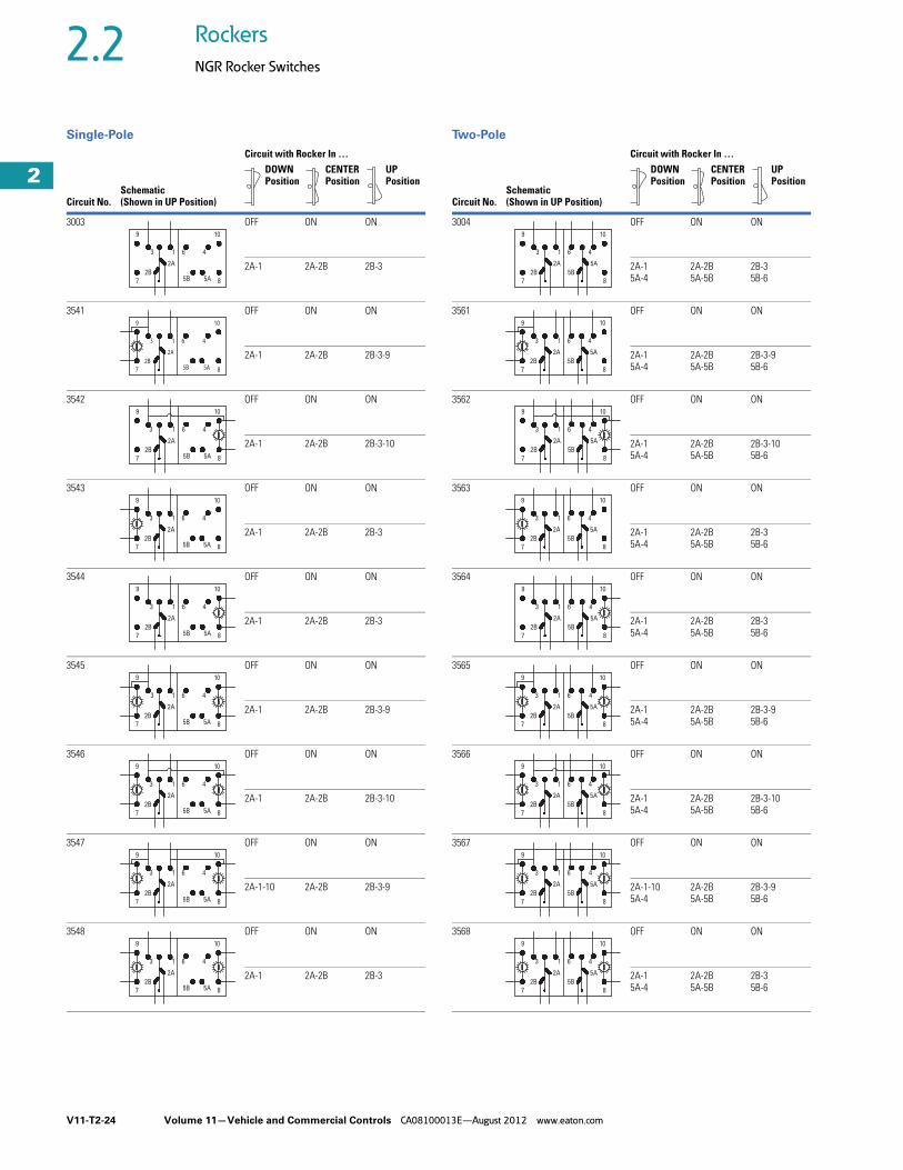
3003 OFF ON ON
2A-1 2A-2B 2B-3
3541 OFF ON ON
2A-1 2A-2B 2B-3-9
3542 OFF ON ON
2A-1 2A-2B 2B-3-10
3543 OFF ON ON
2A-1 2A-2B 2B-3
3544 OFF ON ON
2A-1 2A-2B 2B-3
3545 OFF ON ON
2A-1 2A-2B 2B-3-9
3546 OFF ON ON
2A-1 2A-2B 2B-3-10
3547 OFF ON ON
2A-1-10 2A-2B 2B-3-9
3548 OFF ON ON
2A-1 2A-2B 2B-3
10
4
5A 8
61
2B
3
9
7 5B
2A
2A
5B7
9
3
2B
1 6
85A
4
10
2A
5B7
9
3
2B
1 6
85A
4
10
2A
5B7
9
3
2B
1 6
85A
4
10
2A
5B7
9
3
2B
1 6
85A
4
10
2A
5B7
9
3
2B
1 6
85A
4
10
2A
5B7
9
3
2B
1 6
85A
4
10
2A
5B7
9
3
2B
1 6
85A
4
10
2A
5B7
9
3
2B
1 6
85A
4
10
Circuit with Rocker In …
Circuit No.Schematic(Shown in UP Position)
DOWN Position
CENTER Position
UP Position
3004 OFF ON ON
2A-15A-4
2A-2B5A-5B
2B-35B-6
3561 OFF ON ON
2A-15A-4
2A-2B5A-5B
2B-3-95B-6
3562 OFF ON ON
2A-15A-4
2A-2B5A-5B
2B-3-105B-6
3563 OFF ON ON
2A-15A-4
2A-2B5A-5B
2B-35B-6
3564 OFF ON ON
2A-15A-4
2A-2B5A-5B
2B-35B-6
3565 OFF ON ON
2A-15A-4
2A-2B5A-5B
2B-3-95B-6
3566 OFF ON ON
2A-15A-4
2A-2B5A-5B
2B-3-105B-6
3567 OFF ON ON
2A-1-105A-4
2A-2B5A-5B
2B-3-95B-6
3568 OFF ON ON
2A-15A-4
2A-2B5A-5B
2B-35B-6
2A
7
9
3
2B
1 6
8
4
10
5B
5A
10
4
8
61
2B
3
9
7
2A 5A
5B
10
4
8
61
2B
3
9
7
2A 5A
5B
10
4
8
61
2B
3
9
7
2A 5A
5B
10
4
8
61
2B
3
9
7
2A 5A
5B
10
4
8
61
2B
3
9
7
2A 5A
5B
10
4
8
61
2B
3
9
7
2A 5A
5B
10
4
8
61
2B
3
9
7
2A 5A
5B
10
4
8
61
2B
3
9
7
2A 5A
5B
Volume 11—Vehicle and Commercial Controls CA08100013E—August 2012 www.eaton.com V11-T2-25
2
2
2
2
2
2
2
2
2
2
2
2
2
2
2
2
2
2
2
2
2
2
2
2
2
2
2
2
2
2
2.2Rockers
NGR Rocker Switches
Single-Pole Two-Pole
Circuit with Rocker In …
Circuit No.Schematic(Shown in UP Position)
DOWN Position
CENTER Position
UP Position
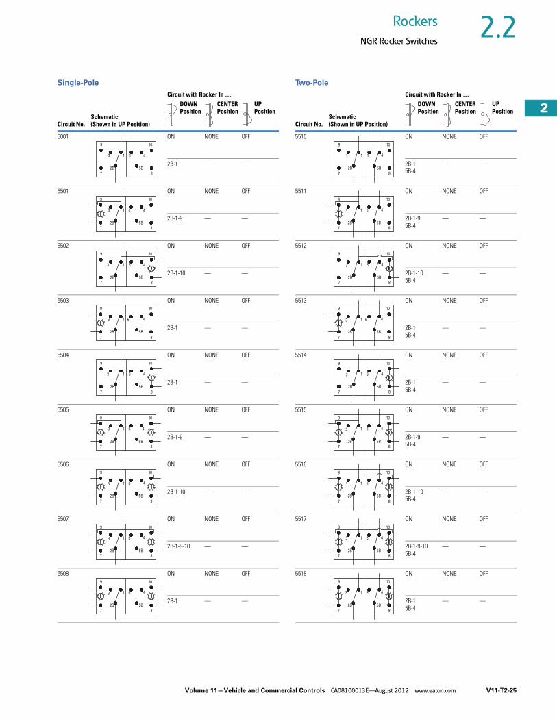
5001 ON NONE OFF
2B-1 — —
5501 ON NONE OFF
2B-1-9 — —
5502 ON NONE OFF
2B-1-10 — —
5503 ON NONE OFF
2B-1 — —
5504 ON NONE OFF
2B-1 — —
5505 ON NONE OFF
2B-1-9 — —
5506 ON NONE OFF
2B-1-10 — —
5507 ON NONE OFF
2B-1-9-10 — —
5508 ON NONE OFF
2B-1 — —
5B
7
9
2B
3 1 6
8
4
10
5B
7
9
2B
3 1 6
8
4
10
5B
7
3
2B
1 6
9
8
4
10
5B
7
2B
9
3 1 6
8
4
10
5B
7
9
2B
3 1 6
8
4
10
5B
7
9
2B
3 61
8
10
4
5B
7
9
1 6
2B
3
8
4
10
3
2B
61
9
7
10
4
8
5B
5B
7
2B
9
3 61
8
10
4
Circuit with Rocker In …
Circuit No.Schematic(Shown in UP Position)
DOWN Position
CENTER Position
UP Position
5510 ON NONE OFF
2B-15B-4
— —
5511 ON NONE OFF
2B-1-95B-4
— —
5512 ON NONE OFF
2B-1-105B-4
— —
5513 ON NONE OFF
2B-15B-4
— —
5514 ON NONE OFF
2B-15B-4
— —
5515 ON NONE OFF
2B-1-95B-4
— —
5516 ON NONE OFF
2B-1-105B-4
— —
5517 ON NONE OFF
2B-1-9-105B-4
— —
5518 ON NONE OFF
2B-15B-4
— —
2B
7 8
5B
3
9 10
461
87
3
2B
9 10
461
5B
9
2B
3
7
10
4
8
61
5B
3
9
2B
7
10
4
8
61
5B
3
2B
7
4
8
61
5B
9 10
2B
7 8
5B
3
9
4
10
1 6
87
3
2B
9 10
461
5B
7
9
2B
3
5B
8
4
10
1 6
3
9
2B
7
4
10
8
1 6
5B

V11-T2-26 Volume 11—Vehicle and Commercial Controls CA08100013E—August 2012 www.eaton.com
2
2
2
2
2
2
2
2
2
2
2
2
2
2
2
2
2
2
2
2
2
2
2
2
2
2
2
2
2
2
2.2 Rockers
NGR Rocker Switches
Single-Pole
Circuit with Rocker In …
Circuit No.Schematic(Shown in UP Position)
DOWN Position
CENTER Position
UP Position
5002 MOM. ON NONE OFF
2B-1 — —
5521 MOM. ON NONE OFF
2B-1-9 — —
5522 MOM. ON NONE OFF
2B-1-10 — —
5523 MOM. ON NONE OFF
2B-1 — —
5524 MOM. ON NONE OFF
2B-1 — —
5525 MOM. ON NONE OFF
2B-1-9 — —
5526 MOM. ON NONE OFF
2B-1-10 — —
5528 MOM. ON NONE OFF
2B-1 — —
2B
7
9
3
5B
1 6 4
8
10
7
9
3
2B 5B
1 6 4
8
10
7
3
2B 5B
1 6 4
8
9 10
7
2B 5B
8
9
3 1 6 4
10
3
7
2B
9
4
5B
1 6
10
8
2B
7
9
3
5B
1 6 4
8
10
7
9
3
2B 5B
1 6 4
8
10
7
2B 5B
8
9
3 1 6 4
10
Circuit with Rocker In …
Circuit No.Schematic(Shown in UP Position)
DOWN Position
CENTER Position
UP Position
5003 ON ON OFF
2A-1 2A-2B 2B-3
5541 ON ON OFF
2A-1 2A-2B 2B-3-9
5542 ON ON OFF
2A-1 2A-2B 2B-3-10
5543 ON ON OFF
2A-1 2A-2B 2B-3
5544 ON ON OFF
2A-1 2A-2B 2B-3
5545 ON ON OFF
2A-1 2A-2B 2B-3-9
5546 ON ON OFF
2A-1 2A-2B 2B-3-10
5547 ON ON OFF
2A-1-10 2A-2B 2B-3-9
5548 ON ON OFF
2A-1 2A-2B 2B-3
5A
9
7
61
5B2B
3
2A
10
4
8
5A7
9
5B
1 63
2B
2A
8
4
10
5A
9
7
1 6
5B
3
2B
2A
4
10
8
5A7
1 6
5B
3
2B
2A
9
4
8
10
5A7 5B2B
9
1 63
2A
8
4
10
5A7
9
5B
1 63
2B
2A
8
4
10
5A7
9
5B
1 63
2B
2A
8
4
10
5A
9
7
1 6
5B
3
2B
2A
4
10
8
5A
9
7
1 6
5B
3
2B
2A
4
10
8
Volume 11—Vehicle and Commercial Controls CA08100013E—August 2012 www.eaton.com V11-T2-27
2
2
2
2
2
2
2
2
2
2
2
2
2
2
2
2
2
2
2
2
2
2
2
2
2
2
2
2
2
2
2.2Rockers
NGR Rocker Switches
Two-Pole
Circuit with Rocker In …
Circuit No.Schematic(Shown in UP Position)
DOWN Position
CENTER Position
UP Position
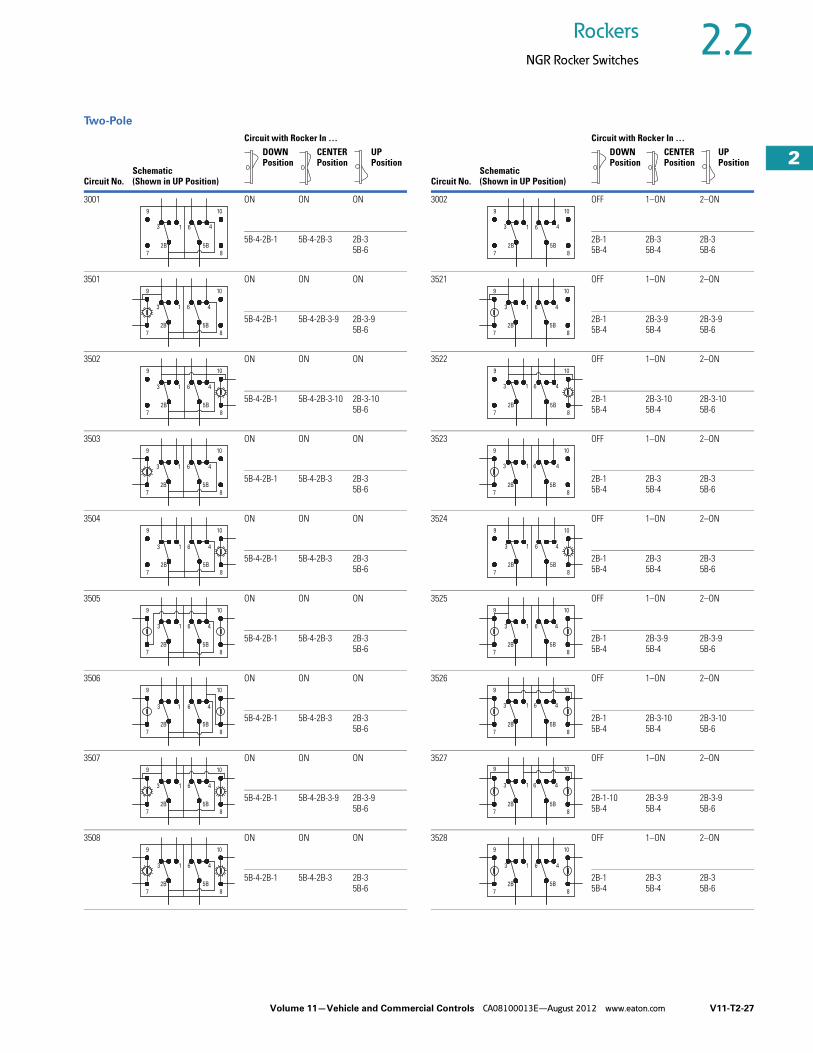
3001 ON ON ON
5B-4-2B-1 5B-4-2B-3 2B-35B-6
3501 ON ON ON
5B-4-2B-1 5B-4-2B-3-9 2B-3-95B-6
3502 ON ON ON
5B-4-2B-1 5B-4-2B-3-10 2B-3-105B-6
3503 ON ON ON
5B-4-2B-1 5B-4-2B-3 2B-35B-6
3504 ON ON ON
5B-4-2B-1 5B-4-2B-3 2B-35B-6
3505 ON ON ON
5B-4-2B-1 5B-4-2B-3 2B-35B-6
3506 ON ON ON
5B-4-2B-1 5B-4-2B-3 2B-35B-6
3507 ON ON ON
5B-4-2B-1 5B-4-2B-3-9 2B-3-95B-6
3508 ON ON ON
5B-4-2B-1 5B-4-2B-3 2B-35B-6
9
7
4
2B
3 1 6
5B
10
8
7
2B
8
5B
9
1 63
10
4
7
9
1 6
2B
3
8
10
5B
4
7
43
2B 5B
61
8
9 10
9
7
43
2B 5B
61
10
8
10
8
5B
4613
2B
7
9
10
8
5B
461
2B
3
7
9
1 63 4
2B 5B
10
87
9
9
7
43
2B 5B
61
10
8
Circuit with Rocker In …
Circuit No.Schematic(Shown in UP Position)
DOWN Position
CENTER Position
UP Position
3002 OFF 1–ON 2–ON
2B-15B-4
2B-35B-4
2B-35B-6
3521 OFF 1–ON 2–ON
2B-15B-4
2B-3-95B-4
2B-3-95B-6
3522 OFF 1–ON 2–ON
2B-15B-4
2B-3-105B-4
2B-3-105B-6
3523 OFF 1–ON 2–ON
2B-15B-4
2B-35B-4
2B-35B-6
3524 OFF 1–ON 2–ON
2B-15B-4
2B-35B-4
2B-35B-6
3525 OFF 1–ON 2–ON
2B-15B-4
2B-3-95B-4
2B-3-95B-6
3526 OFF 1–ON 2–ON
2B-15B-4
2B-3-105B-4
2B-3-105B-6
3527 OFF 1–ON 2–ON
2B-1-105B-4
2B-3-95B-4
2B-3-95B-6
3528 OFF 1–ON 2–ON
2B-15B-4
2B-35B-4
2B-35B-6
3 1
9
2B
7
4
10
6
5B
8
2B 5B
3 461
8
10
7
9
2B
7
9
3
8
4
5B
61
10
2B
3 1
9
7
4
5B
10
6
8
13
2B
9
7
4
10
6
5B
8
9
3
7
2B
61 4
5B
8
10
2B
7
13
9
5B
8
10
46
9
3
7
2B
6 4
10
8
5B
1
3 1
2B
9
7
4
10
6
5B
8

V11-T2-28 Volume 11—Vehicle and Commercial Controls CA08100013E—August 2012 www.eaton.com
2
2
2
2
2
2
2
2
2
2
2
2
2
2
2
2
2
2
2
2
2
2
2
2
2
2
2
2
2
2
2.2 Rockers
NGR Rocker Switches
Two-Pole
Circuit with Rocker In …
Circuit No.Schematic(Shown in UP Position)
DOWN Position
CENTER Position
UP Position
3005 MOM. ON ON MOM. ON
2B-15B-4
2B-15B-6
2B-35B-6
3581 MOM. ON ON MOM. ON
2B-15B-4
2B-15B-6
2B-3-95B-6
3582 MOM. ON ON MOM. ON
2B-15B-4
2B-15B-6
2B-3-105B-6
3583 MOM. ON ON MOM. ON
2B-15B-4
2B-15B-6
2B-35B-6
3584 MOM. ON ON MOM. ON
2B-15B-4
2B-15B-6
2B-35B-6
3585 MOM. ON ON MOM. ON
2B-15B-4
2B-15B-6
2B-3-95B-6
3586 MOM. ON ON MOM. ON
2B-15B-4
2B-15B-6
2B-3-105B-6
3587 MOM. ON ON MOM. ON
2B-1-105B-4
2B-1-105B-6
2B-3-95B-6
3588 MOM. ON ON MOM. ON
2B-15B-4
2B-15B-6
2B-35B-6
1
2B
3
7
9
8
5B
4
10
6
13
2B
9
7
6
10
4
5B
8
1
9
3
2B
7
10
6 4
5B
8
3 1 6 4
2B
7 8
5B
9 10
1
2B
7
3
9
8
5B
10
46
13
2B
9
7
6
10
4
5B
8
13
2B
7
9
6
10
4
5B
8
13
2B
9
7
6 4
5B
10
8
1
2B
3
7 8
4
5B
6
9 10
Circuit with Rocker In …
Circuit No.Schematic(Shown in UP Position)
DOWN Position
CENTER Position
UP Position
4001 NONE ON MOM. ON
2B-15B-4
2B-15B-4
2B-35B-6
4501 NONE ON MOM. ON
2B-15B-4
2B-15B-4
2B-3-95B-6
4502 NONE ON MOM. ON
2B-15B-4
2B-15B-4
2B-3-105B-6
4503 NONE ON MOM. ON
2B-15B-4
2B-15B-4
2B-35B-6
4504 NONE ON MOM. ON
2B-15B-4
2B-15B-4
2B-35B-6
4505 NONE ON MOM. ON
2B-15B-4
2B-15B-4
2B-3-95B-6
4506 NONE ON MOM. ON
2B-15B-4
2B-15B-4
2B-3-105B-6
4507 NONE ON MOM. ON
2B-1-105B-4
2B-1-105B-4
2B-3-95B-6
4508 NONE ON MOM. ON
2B-15B-4
2B-15B-4
2B-35B-6
87
2B
9
5B
41
10
63
9
7
3 61
2B
10
4
5B
8
9
7
3 61
2B
10
4
5B
8
7
9
8
10
2B
3 1 6 4
5B
7
9
8
10
2B
1 4
5B
63
9
7
3 61
2B
10
4
5B
8
3 61
2B
10
4
5B
87
9
3 61
2B
4
5B
9
7
10
8
7 8
9 10
2B
1 4
5B
63

Volume 11—Vehicle and Commercial Controls CA08100013E—August 2012 www.eaton.com V11-T2-29
2
2
2
2
2
2
2
2
2
2
2
2
2
2
2
2
2
2
2
2
2
2
2
2
2
2
2
2
2
2
2.2Rockers
NGR Rocker Switches
Two-Pole
Circuit with Rocker In …
Circuit No.Schematic(Shown in UP Position)
DOWN Position
CENTER Position
UP Position
5004 ON ON OFF
2A-15A-4
2A-2B5A-5B
2B-35B-6
5561 ON ON OFF
2A-15A-4
2A-2B5A-5B
2B-3-95B-6
5562 ON ON OFF
2A-15A-4
2A-2B5A-5B
2B-3-105B-6
5563 ON ON OFF
2A-15A-4
2A-2B5A-5B
2B-35B-6
5564 ON ON OFF
2A-15A-4
2A-2B5A-5B
2B-35B-6
5565 ON ON OFF
2A-15A-4
2A-2B5A-5B
2B-3-95B-6
5566 ON ON OFF
2A-15A-4
2A-2B5A-5B
2B-3-105B-6
5567 ON ON OFF
2A-1-105A-4
2A-2B5A-5B
2B-3-95B-6
5568 ON ON OFF
2A-15A-4
2A-2B5A-5B
2B-35B-6
2B
3
9
7
5A
5B
10
4
8
61
2A
7
9
3
2B 5B
5A2A
1 6
8
4
10
7
9
3
2B 5B
5A2A
1 6
8
4
10
7
3
2B 5B
5A2A
1 6
8
4
9 10
7
2B 5B
8
9
3
5A2A
1 6 4
10
7
9
3
2B 5B
5A2A
1 6
8
4
10
7
9
3
2B 5B
5A2A
1 6
8
4
10
7
9
3
2B 5B
5A2A
1 6
8
4
10
7
3
2B 5B
5A2A
1 6
8
4
9 10
Circuit with Rocker In …
Circuit No.Schematic(Shown in UP Position)
DOWN Position
CENTER Position
UP Position
5005 2–ON 1–ON OFF
2B-15B-4
2B-35B-4
2B-35B-6
5581 2–ON 1–ON OFF
2B-15B-4
2B-3-95B-4
2B-3-95B-6
5582 2–ON 1–ON OFF
2B-15B-4
2B-3-105B-4
2B-3-105B-6
5583 2–ON 1–ON OFF
2B-15B-4
2B-35B-4
2B-35B-6
5584 2–ON 1–ON OFF
2B-15B-4
2B-35B-4
2B-35B-6
5585 2–ON 1–ON OFF
2B-15B-4
2B-3-95B-4
2B-3-95B-6
5586 2–ON 1–ON OFF
2B-15B-4
2B-3-105B-4
2B-3-105B-6
5587 2–ON 1–ON OFF
2B-1-105B-4
2B-3-95B-4
2B-3-95B-6
5588 2–ON 1–ON OFF
2B-15B-4
2B-35B-4
2B-3-95B-6
6001 ON NONE ON
2A-2B-5A-5B-10-1-4-3
— 3-6-1
7
2B
9
3
8
5B
6
10
41
7
3
2B
9
8
1 6 4
5B
10
7
2B 5B
8
3
9 10
1 6 4
7
9
3
2B
8
6
10
5B
41
7
9
2B
3
8
5B
6
10
41
2B
7
3
9 10
8
5B
41 6
3
7
2B
9
6 4
8
5B
1
10
2B
7
5B
8
3
9
1
10
46
7
9
2B
3
8
5B
6
10
41
7 2B2A3 1
96 4 5B5A
8
10

V11-T2-30 Volume 11—Vehicle and Commercial Controls CA08100013E—August 2012 www.eaton.com
2
2
2
2
2
2
2
2
2
2
2
2
2
2
2
2
2
2
2
2
2
2
2
2
2
2
2
2
2
2
2.2 Rockers
NGR Rocker Switches
DimensionsApproximate Dimensions in Inches (mm)
Switch Base with Rocker Button
0.523 ± 0.005
(13.28 ± 0.13)
0.257 ± 0.005
(6.53 ± 0.13)
1.800 Max.
(45.42 Max.)
0.667 ± 0.005
(16.94 ± 0.13)
0.401 ± 0.005
(10.19 ± 0.13)
41
79
8
2B
2A
USA
3
10
5B
5A 6
0.855 ± 0.010
(21.72 ± 0.25)
0.462 ± 0.005
(11.73 ± 0.13)
0.100 ± 0.005
(2.54 ± 0.13)
1.970 ± 0.010
(50.04 ± 0.25)
1.024 ± .010
(26.01 ± 0.25)
C
BA
0.867 ± 0.005
(22.02 ± 0.13)
1.734 ± 0.005
(44.04 ± 0.13) Panel Opening
Panel Thickness:
0.039 to 0.157 in
(1.00 to 4.00) mm
(Best results
obtained between
0.059 and 0.118 in
[1.50 and 3.00 mm])
0.054 ± 0.005
(1.37 ± 0.13)
0.500 ± 0.010
(12.70 ± 0.25)
AR
EA
“B
”
LE
GE
ND
On Indicator “A” On Indicator “B”
7 4 5A 5B 6 8
1032B2A19
0.250 ± 0.005
(6.35 ± 0.13)
0.408 ± 0.010
(10.36 ± 0.25)
0.345 ± 0.010
(8.76 ± 0.25)
1.970 ± 0.010
(50.04 ± 0.25)
1.024 ± 0.010
(26.01 ± 0.25)
0.500 Max.
(12.70 Max.)
0.320 Max.
(8.13 Max.)
0.500 Max.
(12.70 Max.)
ROADLAMP
Orientation
Examples of “Standard”
Orientation of Icons
0.144 ± 0.005
(3.66 ± 0.13)
Terminals
8 and 10
Terminals
7 and 9
Decorative
Rocker
SIL Rocker
(Snap-In Lens)
AR
EA
“A
”
LE
GE
ND
AR
EA
“B
”
LE
GE
ND
AR
EA
“A
”
LE
GE
ND
0.320 Max.
(8.13 Max.)
0.0305/0.032
(0.775/0.813)

Volume 11—Vehicle and Commercial Controls CA08100013E—August 2012 www.eaton.com V11-T2-31
2
2
2
2
2
2
2
2
2
2
2
2
2
2
2
2
2
2
2
2
2
2
2
2
2
2
2
2
2
2
2.2Rockers
NGR Rocker Switches
Approximate Dimensions in Inches (mm)
Locking Rocker
Indicator
Sealed Rocker
Label Rocker
AB
C
LE
GE
ND
0.345 ± 0.010
(8.76 ± 0.25)
AR
EA
“B
”
0.245 ± 0.005
(6.22 ± 0.13)
0.320 ± 0.005 Max.
(8.13 ± 0.13 Max.)
1.970 ± 0.010
(50.04 ± 0.25)
1.024 ± 0.010
(26.0 ± 0.25)0.500 ± 0.005 Max.
(12.70 ± 0.13 Max.)
1.800 Max.
(45.42 Max.)
0.100 ± 0.005
(2.54 ± 0.13)
0.408 ± 0.010
(10.36 ± 0.25)
1.970 ± 0.010
(50.04 ± 0.25)
1.800 Max.
(45.42 Max.)
0.100 ± 0.005
(2.54 ± 0.13)
1.024 ± 0.010
(26.01 ± 0.25)
0.095 ± 0.005
(2.42 ± 0.13)
0.500 Max.
(12.70 Max.)
0.320 Max.
(8.13 Max.)
0.408 ± 0.010
(10.36 ± 0.25)
LE
GE
ND
AR
EA
“A
”
LE
GE
ND
AR
EA
“B
”
0.0305/0.032
(0.775/0.813)
C
AB
1.450 ± 0.040
(36.83 ± 1.02)
0.060 ± 0.010
(1.52 ± 0.25)
Panel Seal
1.970 ± 0.010
(50.04 ± 0.25)
1.024 ± 0.010
(26.01 ± 0.25)
0.500 Max.
(12.70 Max.)
0.320 Max.
(8.13 Max.)
0.408 ± 0.010
(10.36 ± 0.25)
0.345 ± 0.010
(8.76 ± 0.25)
0.420 ± 0.005
(10.67 ± 0.13)
LE
GE
ND
AR
EA
“A
”
LE
GE
ND
AR
EA
“B
”
12° ± 1°
0.580 ± 0.008
(14.73 ± 0.020)
1.128 ± 0.010
(28.65 ± 0.25)
0.020 ± 0.005
(5.08 ± 0.13)
R0.060 ± 0.005
(R1.52 ± 0.13)
0.470 ± 0.010
(11.94 ± 0.25)
0.375 ± 0.010
(9.53 ± 0.25)
Surface Length Along Bottom
Note: Graphics window may be on both ends or either end of part.
Dimensions shown are typical.
Rotated 12° CCW
Graphics Window

Volume 11—Vehicle and Commercial Controls CA08100013E—August 2012 www.eaton.com V11-T2-77
2
2
2
2
2
2
2
2
2
2
2
2
2
2
2
2
2
2
2
2
2
2
2
2
2
2
2
2
2
2
2.12Rockers
Accessories
Approximate Dimensions in Inches (mm)
Gang Mounting System
NGR, Euro-Look and ESPORT Panel Plugs EURO SR Panel Plugs
1.030
(26.16)
2.026 + 0.010
(51.46 + 0.25/– 0.000)
3.056 + 0.010
(77.62 + 0.51/– 0.000)
2.060 (52.32)
1.897
(48.18)
R 0.125
(R 3.18)0.867
(22.02)
1.734
(44.02)
2.000
(50.8)
2.280
(57.91)
End
Bezel
R 0.187 (R 4.75)
R 0.165 (R 4.19) 0.661
(16.79)
0.150
(3.81)
1.200
(30.48)
0.494
(12.55)1.009
(25.63)
(2) End Bezels
Panel Opening
for 2 End Bezels
(2) End Bezels and (1) Center Bezel
Panel Opening—Reference Only
Thickness: 0.039 to 0.078 to 0.118
(1.00 to 2.00 to 3.00)
Dimensions: 2.026 + 0.254/−0.00 (51.46 + 0.254/–0.000)
Plus Number of Center Bezels Times 1.03
Tolerence: +0.254/−0.000 (+ 0.254/–0.000) for Each
Center Bezel up to a Maximum of + 0.0002 (+ 0.050)
1.900 ± 0.020
(48.26 + 0.51/– 0.00)
1.900 ± 0.020
(48.26 + 0.51/– 0.00)
Bezel Catalog Numbers
End Center
NGR 17-21160 17-21159
Euro-Look 17-19264 17-19263
A
C
B
E
D
1.380
(35.05)
1.530
(38.86)
0.847
(21.51)
Bottom
View1.024
(26.01)
1.970
(50.04)
1.734 + 0.005/– 0.000
(44.04 + 0.13/– 0.00)
Panel Opening
Reference Only
Thickness: 0.030 to 0.190
(0.76 to 4.83)
Panel plug Catalog Number
17-19544-2 for Use with
Euro-Look and ESPORT.
NGR panel plug Catalog
Number 17-21543.
Part will also fit Eaton
gang mounting boxes.
Catalog Numbers
17-19263 and
17-192640.867 + 0.005/– 0.000
(22.02 + 0.13/– 0.00)
Euro-LookESPORT NGR
A 0.080 (2.03) 0.100 (2.54)
B R 0.060 (R 1.52) R 0.080 (R 2.03)
C 0.340 (8.64) 0.335 (8.51)
D 0.530 (13.46) 0.550 (13.97)
E R 0.156 (R 3.96) R 0.250 (R 6.35)
1.255 + 0.009/ –0.001
(31.88 +0.25/ –0.03)
Top
View
R 0.156
(R 3.96)
0.985 ± 0.007
(25.02 ± 0.20)
1.735 ± 0.012
(44.07 ± 0.31)
0.130 ± 0.010
(3.30 ± 0.25)
1.427 ± 0.005
(36.25 ± 0.13)
1.450
(36.83)
0.680
(16.66)0.830
(21.08)
0.820 ± 0.005
(20.83 ± 0.13)
1.190
(30.23)
Panel
Opening
Panel Plug Catalog Number 53-3318
For Use with EURO/SR
Panel Opening—Reference Only
Thickness:
0.040 to 0.140 (1.01 to 3.55)
Best Results Obtained From:
0.080 to 0.125 (2.03 to 3.17)
0.650 +0.010/ –0.001
(16.51 +0.25/ –0.02)
V11-T2-78 Volume 11—Vehicle and Commercial Controls CA08100013E—August 2012 www.eaton.com
2
2
2
2
2
2
2
2
2
2
2
2
2
2
2
2
2
2
2
2
2
2
2
2
2
2
2
2
2
2
2.13 Rockers
Technical Data
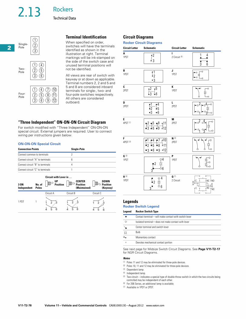
Terminal Identification When specified on order, switches will have the terminals identified as shown in the illustration at right. Terminal markings will be ink-stamped on the side of the switch case and unused terminal positions will not be identified.
All views are rear of switch with keyway or at down as applicable. Terminal numbers 2, 2 and 5 and 5 and 8 are considered inboard terminals for single-, two- and four-pole switches respectively. All others are considered outboard.
“Three Independent” ON-ON-ON Circuit DiagramFor switch modified with “Three Independent” ON-ON-ON special circuit. External jumpers are required. User to connect wiring per instructions given below.
ON-ON-ON Special Circuit
Circuit DiagramsRocker Circuit Diagrams
LegendsRocker Switch Legend
See next page for Midsize Switch Circuit Diagrams. See Page V11-T2-17 for NGR Circuit Diagrams.
Notes1 Poles 11 and 12 may be eliminated for three-pole devices.2 Poles 10, 11 and 12 may be eliminated for three-pole devices.3 Dependent lamp.4 Independent lamp.5 Two circuit—indicates a special type of double-throw switch in which the two circuits being
controlled may be independent of each other.6 For 206 Series, an additional lamp is available.7 Available in 1PDT or 2PDT.
Connection Points Single-Pole
Connect common to terminals 2
Connect circuit “A” to terminals 6
Connect circuit “B” to terminals 4
Connect circuit “C” to terminals 1
Circuit with Lever in …
3 ON Independent
No. of Poles
UP Position
CENTER Position (Maintained)
DOWN Position (Keyway)
1 PDT 1
Circuit A Circuit B Circuit C
1
2
3
1
2
3
4
5
6
1
2
3
4
5
6
7
8
9
10
11
12
Single-Pole
Two-Pole
Four-Pole
1 2 3
4 5 6
1 2 3
4 5 6
1 2 3
4 5 6
Circuit Letter Schematic Circuit Letter Schematic
A1PST
I2 Circuit 5
B1PDT
J1PST
C2PST
K1PDT
D2PDT
L2PST
E 4PST 1
M2PST
F4PDT 2
N 6
2PDT
G 3
1PSTP1PDT
H 4
1PDTQ 7
2 Circuit
Legend Rocker Switch Type
Contact terminal—will make contact with switch lever
Isolated terminal—does not make contact with lever
Center terminal and switch lever
Bulb
Momentary contact
Denotes mechanical contact portion
3
2
3 6
1 4
23
1
3
2
6
5
23
156
4 4
31
2
3
2
6
5
9
8
12
11
1 3
2 4
2
3
1
5
6
4
8
9
7
11
12
10
3
24
6
3
24
6
BA
C
C
NCNOGH
NONC

Volume 11—Vehicle and Commercial Controls CA08100013E—August 2012 www.eaton.com V11-T2-79
2
2
2
2
2
2
2
2
2
2
2
2
2
2
2
2
2
2
2
2
2
2
2
2
2
2
2
2
2
2
2.13Rockers
Technical Data
Midsize Switch Circuit Diagrams 1
Non-Illuminated Illuminated
Notes1 Terminal numbers 1, 2 and 3 denote single-pole base.
Terminal numbers 11, 12, 113, 24, 25 and 26 denote two-pole base.2 Single-pole in two-pole base with lamp independently wired.3 Two-pole—independently wired lamp.
Circuit Number(Circuit Designator)
Circuit with Rocker In …
Schematic
DOWNPosition
CENTERPosition
UPPosition
11PST
OFF NONE ON
21PST
OFF NONE ON
31PST
OFF NONE MOM. ON
41PST
OFF NONE ON
51PDT
ON NONE ON
61PDT
ON OFF ON
71PDT
MOM. ON NONE ON
81PDT
ON OFF MOM. ON
91PDT
MOM. ON OFF MOM. ON
102PST
OFF NONE ON
112PST
OFF NONE MOM. ON
122PST
MOM. OFF NONE ON
132PDT
ON NONE ON
142PDT
ON OFF ON
152PDT
MOM. ON NONE ON
162PDT
ON OFF MOM. ON
172PDT
MOM. ON OFF MOM. ON
1
2
11
12
1
2
1
2
1
2 3
1
3 2
1
3 2
1
3 2
1
23
11 24
12 25
11 24
12 25
11 24
12 25
11 24
12 31 6252
11 24
13 26 2512
11 24
13 26 2512
11 24
21 526231
11 24
13 12 26 25
Circuit Number(Circuit Designator)
Circuit with Rocker In …
Schematic
DOWNPosition
CENTERPosition
UPPosition
181PST
OFF NONE ON
191PST
OFF NONE ON
201PST 2
OFF NONE ON
211PST
OFF NONE MOM. ON
221PDT
MOM. OFF NONE ON
231PDT
ON NONE ON
241PDT
ON OFF ON
251PDT
MOM. ON NONE ON
261PDT
ON OFF ON
272PST
ON OFF ON
282PST
ON NONE ON
292PST 3
ON NONE ON
302PDT
MOM. ON NONE MOM. ON
312PDT
ON NONE ON
32Indicator
— — —
1 2
3
11 2412
1125 26
12
1 2
3
11 13
12
24 13
25 26
24
26 25
13
24
26 25
13
26
24
25
13
26
24
25
13
12 25
2411
1113 26
12
24
25
2411
2512
12 25
2411
3 2
V11-T2-80 Volume 11—Vehicle and Commercial Controls CA08100013E—August 2012 www.eaton.com
2
2
2
2
2
2
2
2
2
2
2
2
2
2
2
2
2
2
2
2
2
2
2
2
2
2
2
2
2
2
2.14 Rockers
Symbols Library
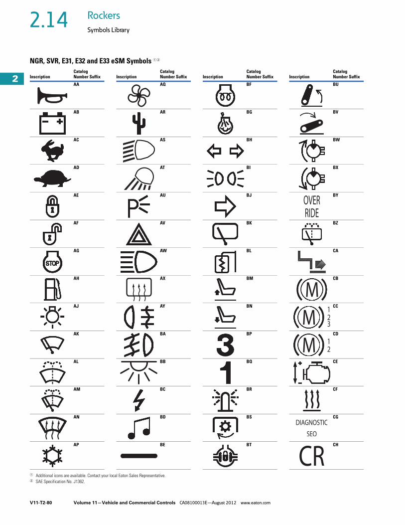
NGR, SVR, E31, E32 and E33 eSM Symbols 1 2
1 Additional icons are available. Contact your local Eaton Sales Representative. 2 SAE Specification No. J1362.
InscriptionCatalog Number Suffix
AA
AB
AC
AD
AE
AF
AG
AH
AJ
AK
AL
AM
AN
AP
InscriptionCatalog Number Suffix
AQ
AR
AS
AT
AU
AV
AW
AX
AY
BA
BB
BC
BD
BE
InscriptionCatalog Number Suffix
BF
BG
BH
BI
BJ
BK
BL
BM
BN
BP
BQ
BR
BS
BT
InscriptionCatalog Number Suffix
BU
BV
BW
BX
BY
BZ
CA
CB
CC
CD
CE
CF
CG
CH

Volume 11—Vehicle and Commercial Controls CA08100013E—August 2012 www.eaton.com V11-T2-81
2
2
2
2
2
2
2
2
2
2
2
2
2
2
2
2
2
2
2
2
2
2
2
2
2
2
2
2
2
2
2.14Rockers
Symbols Library
NGR, SVR, E31, E32 and E33 eSM Symbols 1 2
1 Additional icons are available. Contact your local Eaton Sales Representative. 2 SAE Specification No. J1362.
InscriptionCatalog Number Suffix
CI
CJ
CK
CL
CM
CN
CP
CQ
CR
CS
CT
CU
CV
CW
InscriptionCatalog Number Suffix
CX
CY
DA
DB
DC
DD
DE
DF
DG
DH
DJ
DK
DL
DM
InscriptionCatalog Number Suffix
DN
DP
DQ
DR
DS
DT
DU
DV
DW
DX
DY
DZ
EA
EB
InscriptionCatalog Number Suffix
EC
ED
EE
EF
EG
EH
EI
EJ
EK
EL
EM
EN
EO
EP
V11-T2-82 Volume 11—Vehicle and Commercial Controls CA08100013E—August 2012 www.eaton.com
2
2
2
2
2
2
2
2
2
2
2
2
2
2
2
2
2
2
2
2
2
2
2
2
2
2
2
2
2
2
2.14 Rockers
Symbols Library
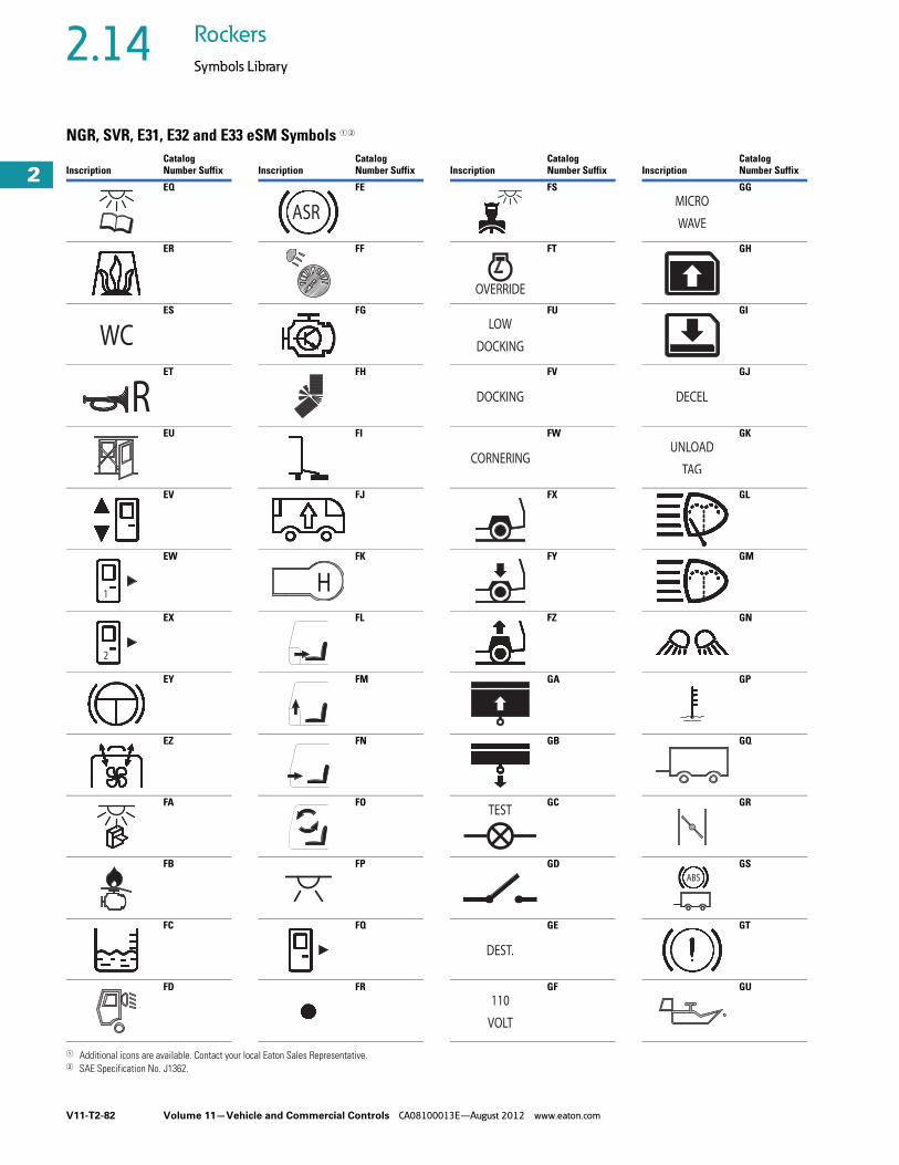
NGR, SVR, E31, E32 and E33 eSM Symbols 1 2
1 Additional icons are available. Contact your local Eaton Sales Representative. 2 SAE Specification No. J1362.
InscriptionCatalog Number Suffix
EQ
ER
ES
ET
EU
EV
EW
EX
EY
EZ
FA
FB
FC
FD
1
InscriptionCatalog Number Suffix
FE
FF
FG
FH
FI
FJ
FK
FL
FM
FN
FO
FP
FQ
FR
InscriptionCatalog Number Suffix
FS
FT
FU
FV
FW
FX
FY
FZ
GA
GB
GC
GD
GE
GF
InscriptionCatalog Number Suffix
GG
GH
GI
GJ
GK
GL
GM
GN
GP
GQ
GR
GS
GT
GU

Volume 11—Vehicle and Commercial Controls CA08100013E—August 2012 www.eaton.com V11-T2-83
2
2
2
2
2
2
2
2
2
2
2
2
2
2
2
2
2
2
2
2
2
2
2
2
2
2
2
2
2
2
2.14Rockers
Symbols Library
NGR, SVR, E31, E32 and E33 eSM Symbols 1 2
1 Additional icons are available. Contact your local Eaton Sales Representative. 2 SAE Specification No. J1362.
InscriptionCatalog Number Suffix
GV
GW
GY
HA
HB
HC
HD
HE
HF
HG
HH
HJ
HK
HL
PASILLO
LUZ
InscriptionCatalog Number Suffix
HM
HN
HP
HQ
HR
HS
HT
HU
HV
HW
HY
JA
JB
JC
InscriptionCatalog Number Suffix
JD
JE
JF
JG
JH
JJ
JK
JL
JM
JN
JP
JQ
JR
JS
InscriptionCatalog Number Suffix
JT
JU
JV
JW
JX
JY
JZ
KA
KB
KC
KD
KE
KF
KG
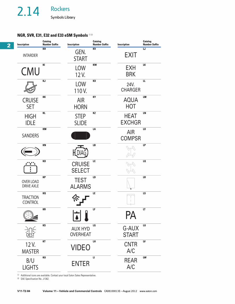
V11-T2-84 Volume 11—Vehicle and Commercial Controls CA08100013E—August 2012 www.eaton.com
2
2
2
2
2
2
2
2
2
2
2
2
2
2
2
2
2
2
2
2
2
2
2
2
2
2
2
2
2
2
2.14 Rockers
Symbols Library
NGR, SVR, E31, E32 and E33 eSM Symbols 1 2
1 Additional icons are available. Contact your local Eaton Sales Representative. 2 SAE Specification No. J1362.
InscriptionCatalog Number Suffix
KH
KI
KJ
KK
KL
KM
KN
KO
KP
KQ
KR
KS
KT
KU
InscriptionCatalog Number Suffix
KV
KW
KX
KY
KZ
LA
LB
LC
LD
LE
LF
LG
LH
LI
DIAG
CRUISESELECT
TESTALARMS
OVERHEATAUX HYD
VIDEO
ENTER
InscriptionCatalog Number Suffix
LJ
LK
LL
LM
LN
LO
LP
LQ
LR
LS
LT
LU
LV
LW
EXIT
BRKEXH
24V.CHARGER
AQUAHOT
HEATEXCHGR
AIRCOMPSR
PAG-AUXSTART
A/CCNTR
REARA/C

Volume 11—Vehicle and Commercial Controls CA08100013E—August 2012 www.eaton.com V11-T2-85
2
2
2
2
2
2
2
2
2
2
2
2
2
2
2
2
2
2
2
2
2
2
2
2
2
2
2
2
2
2
2.14Rockers
Symbols Library
NGR Only Symbols 1 2
1 Additional icons are available. Contact your local Eaton Sales Representative. 2 SAE Specification No. J1362.
InscriptionCatalog Number Suffix
LX
LY
LZ
MA
MB
MC
MD
ME
MF
MG
MH
MI
MJ
MK
DIAG
CODE
LIGHT
POSITION
MASTERWARN
UPPERWARN
LOWERWARN
COMPTLIGHTS
WORKLIGHTS
FASTIDLE
MIRRORHEAT
GENPTO
WIGWAG
SIRENBRAKE
LEFTSCENE
InscriptionCatalog Number Suffix
ML
MM
MN
MO
MP
MS
MT
MU
MV
MW
MX
MY
MZ
NA
InscriptionCatalog Number Suffix
NB
NC
ND
NE
NF
NG
NH
NI
NJ
NK
NL
NM
NN
NO
InscriptionCatalog Number Suffix
NP
NQ
NR
NS
NT
NU
NV
NW
NX
NY
NZ
PA
PB
PC

V11-T2-86 Volume 11—Vehicle and Commercial Controls CA08100013E—August 2012 www.eaton.com
2
2
2
2
2
2
2
2
2
2
2
2
2
2
2
2
2
2
2
2
2
2
2
2
2
2
2
2
2
2
2.14 Rockers
Symbols Library
NGR Only Symbols 1 2
1 Additional icons are available. Contact your local Eaton Sales Representative. 2 SAE Specification No. J1362.
InscriptionCatalog Number Suffix
PD
PE
PF
PG
PH
PI
PJ
PK
PL
PM
PN
PP
PQ
PR
InscriptionCatalog Number Suffix
PS
PT
PU
PV
PW
PX
PY
PZ
RA
RB
RC
RD
RE
RF
AXLE
OVER
DRIVELOAD
InscriptionCatalog Number Suffix
RG
RH
RI
RJ
RK
RL
RM
RN
RP
RQ
RS
RT
RU
RV
ENGINECHECK
CODEABS
InscriptionCatalog Number Suffix
RW
RX
RY
RZ
SA
SB
SC
SD
SE
SF
SG
SH
SJ
SK
D
H

Volume 11—Vehicle and Commercial Controls CA08100013E—August 2012 www.eaton.com V11-T2-87
2
2
2
2
2
2
2
2
2
2
2
2
2
2
2
2
2
2
2
2
2
2
2
2
2
2
2
2
2
2
2.14Rockers
Symbols Library
NGR Only Symbols 1 2
1 Additional icons are available. Contact your local Eaton Sales Representative. 2 SAE Specification No. J1362.
InscriptionCatalog Number Suffix
SL
SM
SN
SP
SQ
SR
SS
ST
SU
SV
SW
SX
SY
SZ
Mode
InscriptionCatalog Number Suffix
TA
TB
TC
TD
TE
TF
TG
TH
TJ
TK
TL
TM
TN
TP
InscriptionCatalog Number Suffix
TQ
TR
TS
TT
TU
TV
TW
TX
TY
TZ
UA
UB
UC
UD
InscriptionCatalog Number Suffix
UE
UF
UG
UH
UK
UL
UM
UN
UP
UR
US
UT
UU
UV

V11-T2-88 Volume 11—Vehicle and Commercial Controls CA08100013E—August 2012 www.eaton.com
2
2
2
2
2
2
2
2
2
2
2
2
2
2
2
2
2
2
2
2
2
2
2
2
2
2
2
2
2
2
2.14 Rockers
Symbols Library
NGR Only Symbols 1 2
1 Additional icons are available. Contact your local Eaton Sales Representative. 2 SAE Specification No. J1362.
InscriptionCatalog Number Suffix
UW
UX
UY
UZ
VA
VB
VC
VD
VE
VF
VG
VH
VK
VL
InscriptionCatalog Number Suffix
VM
VN
VP
VR
VS
VT
VU
VV
VW
VX
VY
VZ
WA
WB
InscriptionCatalog Number Suffix
WC
WD
WE
WF
WG
WH
WJ
WK
WL
WM
WN
WP
WR
WS
InscriptionCatalog Number Suffix
WT
WU
WV
WW
WX
WY
WZ
XA
XB
XC
XD
XE
XF
XG

Volume 11—Vehicle and Commercial Controls CA08100013E—August 2012 www.eaton.com V11-T2-89
2
2
2
2
2
2
2
2
2
2
2
2
2
2
2
2
2
2
2
2
2
2
2
2
2
2
2
2
2
2
2.14Rockers
Symbols Library
NGR Only Symbols 1 2
1 Additional icons are available. Contact your local Eaton Sales Representative. 2 SAE Specification No. J1362.
InscriptionCatalog Number Suffix
XH
XJ
XK
XL
XM
XN
XP
XR
XS
XT
XU
XV
XW
XX
InscriptionCatalog Number Suffix
XY
XZ
YA
YB
YC
YD
YE
YF
YG
YH
YJ
YK
YL
YM
InscriptionCatalog Number Suffix
YN
YP
YQ
YR
YS
YT
YU
YV
YW
YX
YY
YZ
ZA
ZB
InscriptionCatalog Number Suffix
ZC
ZD
ZE
ZF
ZG
ZH
ZJ
ZK
ZL
ZM
ZN
ZP
ZR
ZS

V11-T2-90 Volume 11—Vehicle and Commercial Controls CA08100013E—August 2012 www.eaton.com
2
2
2
2
2
2
2
2
2
2
2
2
2
2
2
2
2
2
2
2
2
2
2
2
2
2
2
2
2
2
2.14 Rockers
Symbols Library
NGR Only Symbols 1 2
1 Additional icons are available. Contact your local Eaton Sales Representative. 2 SAE Specification No. J1362.
InscriptionCatalog Number Suffix
ZT
ZU
ZV
ZW
ZX
ZY
ZZ
A1
B1
C1
D1
E1
F1
G1
InscriptionCatalog Number Suffix
H1
J1
K1
L1
M1
N1
P1
R1
S1
T1
U1
V1
W1
X1
InscriptionCatalog Number Suffix
Y1
Z1
A2
B2
C2
D2
E2
F2
G2
H2
J2
K2
L2
M2
InscriptionCatalog Number Suffix
N2
P2
R2
S2
T2
U2
V2
W2
X2
Y2
Z2
A3
B3
C3

Volume 11—Vehicle and Commercial Controls CA08100013E—August 2012 www.eaton.com V11-T2-91
2
2
2
2
2
2
2
2
2
2
2
2
2
2
2
2
2
2
2
2
2
2
2
2
2
2
2
2
2
2
2.14Rockers
Symbols Library
NGR Only Symbols 1 2
1 Additional icons are available. Contact your local Eaton Sales Representative. 2 SAE Specification No. J1362.
InscriptionCatalog Number Suffix
D3
E3
F3
G3
H3
J3
K3
L3
M3
N3
P3
Q3
R3
S3
InscriptionCatalog Number Suffix
T3
U3
V3
W3
X3
Y3
Z3
A4
B4
C4
D4
E4
F4
G4
InscriptionCatalog Number Suffix
H4
J4
K4
L4
M4
N4
P4
R4
S4
T4
U4
V4
W4
X4
InscriptionCatalog Number Suffix
Y4
Z4
A5
B5
C5
D5
E5
F5
G5
H5
J5
K5
L5
M5
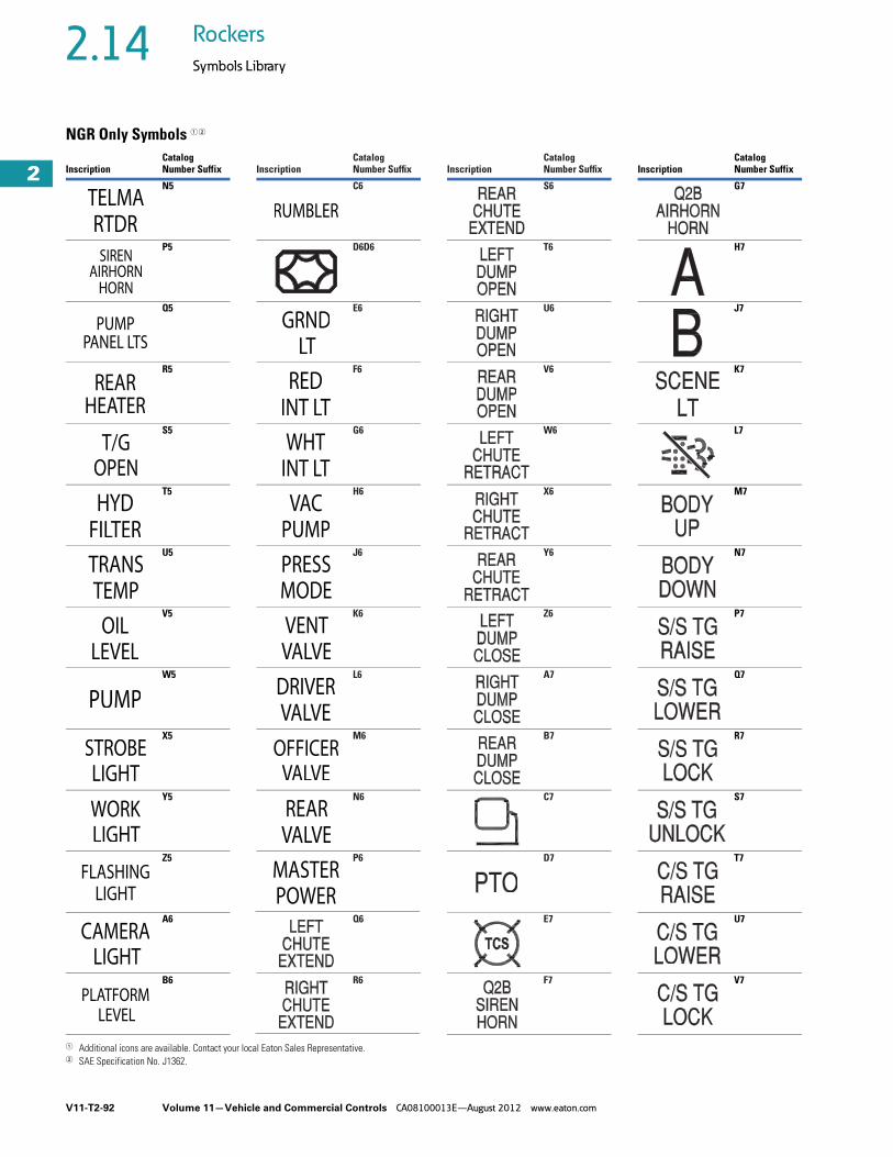
V11-T2-92 Volume 11—Vehicle and Commercial Controls CA08100013E—August 2012 www.eaton.com
2
2
2
2
2
2
2
2
2
2
2
2
2
2
2
2
2
2
2
2
2
2
2
2
2
2
2
2
2
2
2.14 Rockers
Symbols Library
NGR Only Symbols 1 2
1 Additional icons are available. Contact your local Eaton Sales Representative. 2 SAE Specification No. J1362.
InscriptionCatalog Number Suffix
N5
P5
Q5
R5
S5
T5
U5
V5
W5
X5
Y5
Z5
A6
B6
InscriptionCatalog Number Suffix
C6
D6D6
E6
F6
G6
H6
J6
K6
L6
M6
N6
P6
Q6
R6
InscriptionCatalog Number Suffix
S6
T6
U6
V6
W6
X6
Y6
Z6
A7
B7
C7
D7
E7
F7
InscriptionCatalog Number Suffix
G7
H7
J7
K7
L7
M7
N7
P7
Q7
R7
S7
T7
U7
V7

Volume 11—Vehicle and Commercial Controls CA08100013E—August 2012 www.eaton.com V11-T2-93
2
2
2
2
2
2
2
2
2
2
2
2
2
2
2
2
2
2
2
2
2
2
2
2
2
2
2
2
2
2
2.14Rockers
Symbols Library
NGR Only Symbols 1 2
1 Additional icons are available. Contact your local Eaton Sales Representative. 2 SAE Specification No. J1362.
InscriptionCatalog Number Suffix
W7
X7
Y7
Z7
A8
B8
C8
D8
E8
F8
G8
H8
J8
K8
InscriptionCatalog Number Suffix
L8
M8
N8
P8
Q8
R8
S8
T8
U8
V8
W8
X8
Y8
Z8
InscriptionCatalog Number Suffix
A9
B9
C9
D9
E9
F9
G9
H9
J9
K9
L9
M9
N9
P9
InscriptionCatalog Number Suffix
Q9
R9
S9
T9
U9
V9
W9
X9
Y9
Z9
1A
1B
1C
1D
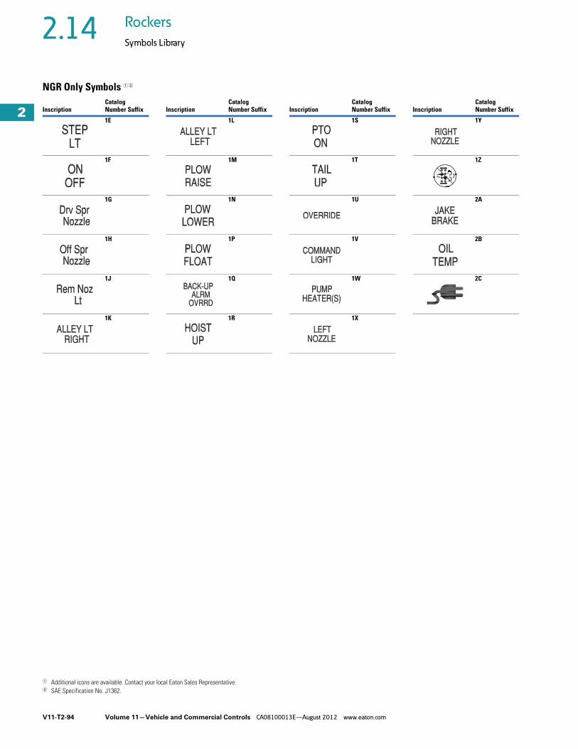
V11-T2-94 Volume 11—Vehicle and Commercial Controls CA08100013E—August 2012 www.eaton.com
2
2
2
2
2
2
2
2
2
2
2
2
2
2
2
2
2
2
2
2
2
2
2
2
2
2
2
2
2
2
2.14 Rockers
Symbols Library
NGR Only Symbols 1 2
1 Additional icons are available. Contact your local Eaton Sales Representative. 2 SAE Specification No. J1362.
InscriptionCatalog Number Suffix
1E
1F
1G
1H
1J
1K
InscriptionCatalog Number Suffix
1L
1M
1N
1P
1Q
1R
InscriptionCatalog Number Suffix
1S
1T
1U
1V
1W
1X
InscriptionCatalog Number Suffix
1Y
1Z
2A
2B
2C


