
BUSINEVRF Series.The most advanced commercial air conditioning system.
R410A


IndexContents VRF Series R410A
VRF Series R410A pag. 04
Outdoor units pag. 20
Indoor units pag. 30
Controls pag. 48
Complementary productspag. 56
Accessories pag. 60

4
The most advanced commercial air conditioning solution
The most advanced commercial air conditioning solution.As a world-wide leader in electronics, Toshiba is committedto delivering the highest standardsof quality and innovation in all of the industries in which the company is a major player.These principles are clearlydemonstrated in the air conditioningdivision, where Toshiba continues to develop market-leading productsfor both commercial and residentialcustomers.In 1981 Toshiba was the firstmanufacturer to launch airconditioners with invertertechnology, and now Toshiba has a comprehensive range
of split systems designed for usewith non-ozone depletingrefrigerants. Toshiba entered the VRF market in 1999 with the advanced Super Multi system,and after a very fast upgrading, in 2004 launched the new SuperMMS VRF system, optimised for use with energy-efficient, non-ozone-depleting R410Arefrigerant, followed by the SuperHeat Recovery Multi, the 3 pipemodular system.For the last 47 years Toshiba'sambitious main objective has beento design and manufacture state-of-the-art air conditioning,
with innovative technologies in all areas - from superiorperformance to reduced powerconsumption, from air treatment to expert assistance.
5
cial
VRF R410A Series
Innovative technologies
New DC twin-rotary compressors
Unique dual inverter drive in every
outdoor unit
New large-diameter fan design for
improved air flow
New heat transfer pipe design for
greater energy efficiency
Improved fan blade design for
smoother air flow and less turbulence
Optimised for energy efficient non-
ozone-depleting R410A refrigerant
Extended pipe runs for greater
application flexibility
Vector control inverter
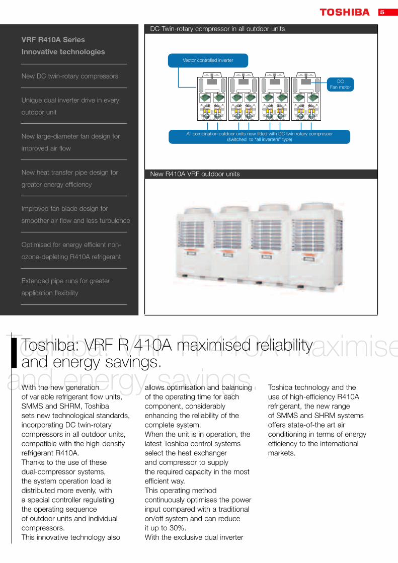
DC Twin-rotary compressor in all outdoor units
New R410A VRF outdoor units
Toshiba: VRF R-410A maximised reliabilityand energy savings.
Toshiba: VRF R 410A maximised reliabilityand energy savings.With the new generation of variable refrigerant flow units,SMMS and SHRM, Toshiba sets new technological standards,incorporating DC twin-rotarycompressors in all outdoor units,compatible with the high-densityrefrigerant R410A.Thanks to the use of these dual-compressor systems, the system operation load isdistributed more evenly, with a special controller regulating the operating sequence of outdoor units and individualcompressors.This innovative technology also
allows optimisation and balancingof the operating time for eachcomponent, considerablyenhancing the reliability of thecomplete system.When the unit is in operation, thelatest Toshiba control systemsselect the heat exchanger and compressor to supply the required capacity in the mostefficient way.This operating methodcontinuously optimises the powerinput compared with a traditionalon/off system and can reduce it up to 30%.With the exclusive dual inverter
Toshiba technology and the use of high-efficiency R410Arefrigerant, the new range of SMMS and SHRM systemsoffers state-of-the art airconditioning in terms of energyefficiency to the internationalmarkets.
Vector controlled inverter
All combination outdoor units now fitted with DC twin rotary compressor(switched to “all inverters” type)
DCFan motor

6
Complete peace-of-mind from Toshiba: stable operation.
Complete peace-of-mind from Toshiba: stable operation.With the use of the special inverter-controlled compressors, the new SMMS and SHRM ranges offer a significant reduction in mechanicaland electrical stress. This is due to the more gradual start-up
compared with traditional on/offcompressors, increasing thedurability and reliability of thecomponents. The models of thenew range also feature the activeOil Management System, that
constantly checks the oil level in each compressor andautomatically transfers oil fromanother outdoor unit, if an oilshortage is detected in anycompressor.
Business
Energy savingsaccording to Toshiba.
Energy savingsaccording to Toshiba.The advanced electronictechnology in these systemspermits capacity control thatresults in significant energysavings. This objective is achieved thanksto the use of sophisticated invertercontrol and modulating controlvalves in each indoor unit.
These permit linear variation of the refrigerant flow in any circuit,directly proportional to the thermalload, resulting in further energysavings. In fact the power input of the outdoor unit is dramaticallyreduced with the heat loadreduction in the areas served.Another factor of energy
and managment costs savings is that the systems are sized formaximum load, and usuallyoperate at part load.Maintenance costs are alsominimised. No particular routinemaintenance is required, exceptfor the indoor unit filters, that mustbe cleaned periodically.
Maximum care and respect ofMaximum care and respect of the environment.Toshiba’s commitment to theresearch and development of new technologies with zeroimpact on the environment hasled to the launch of the new SMMS cooling only and heatpump ranges and the
SHRM heat recovery range,optimised for the high-efficiencynon-ozone-depleting refrigerantR410A.The use of the sophisticated dual inverter control optimises the load distribution to deliver
the capacity needed to reach and maintain the requiredtemperature, eliminating inefficientpower surges typical for non-inverter systems.

7
m Toshiba:
Unlimited flexibility.
Optimised product choice.
The ultimate inverter system.
Minimised consumption.
Silence, spoke Toshiba.Silence, spoke Toshiba.One of the main Toshibaobjectives is improved quality of life inside, as well as outsidebuildings. The reduced outdoorunit noise levels are the result of the study and elimination of all noise level peaks, normally
present during the unit start-upphase, using the automatic sounddampening mode and the night-operation mode. This has resultedin operating noise levels for below50 dB(A).The exclusive use of inverter
compressors also significantlycontributed to these low noiseemission performances,comparable to the rustling of leaves.
VRF.The freedom of choice.
VRF.The freedom of choice.Variable refrigerant flow benefitsfrom the advantages of directexpansion linked to invertercontrol and the mostsophisticated electronic control. This technology has many
advantages, from the systemdesign to the installation andoperation phase.The wide range of indoor unitsmakes VRF the most flexiblechoice to satisfy any equirements.
Precision is our top priority.
Precision is our top priority.With the sophisticated invertercontrol, it is possible to match the actual refrigerant flow to the capacity required by the application for each indoorunit. This results in optimisedefficiency of the refrigerant cycle and increased precision in maintaining the required
temperature, improving comfortfor the occupants. The requiredcapacity and the relating technicalparameters for each indoor unitare electronically transmitted to the outdoor unit in order to optimise the zone loadcalculation and to control theactual refrigerant flow to each
indoor unit, using the specialPulsed Modulating Valves (PMV).

8
0
-10
-20
-30
-40
-50
-60
-51.8 -48.5 -26.18
Compressor development and ecology.
Compressor development and ecology.Conventional 2-in-1 scroll(R407C)
Consists of one inverter-drivencompressor and one fixed-speedcompressor. Each scrollcompressor comprises a fixedscroll (spiral) and an oscillatingscroll. The oscillating scroll fitswithin the fixed scroll. Refrigerant is drawn from the outside of themeshing spirals and squeezedtowards the centre of the scrolls, thereby pressurising the refrigerant. To minimise leakage, the contactforce required between the twoscrolls is considerable and thescroll surfaces must be ubricated. At low compressor speedslubrication efficiency is reduced,resulting in increased compressorwear.
Dual DC twin-rotary (R410A)
Consists of two inverter-driventwin-rotary compressors.A twin-rotary compressor has twofixed compression chambers. An off-centre roller orbits eachchamber to squeeze the refrigerant. The two rollers are both mountedon the same shaft, but are offset to provide counter balance to each other. The contact forcerequired between the roller and chamber wall is lowered. This means that smaller bearingscan be used and lubricationdemand is reduced, saving weightand making this type of compressormore suited to lowspeed operation.
Benefits of usingR410A refrigerant.
Benefits of usingR410A refrigerant.Incorporating the energy-efficient, non-ozone-depletingR410A refrigerant in airconditioning systems deliversmultiple benefits:• zero ozone-depletingpotential.• significant increase in energy efficiency.• reduced pressure lossfor improved performance.
2-in-1 scroll
Standard
92 kg x 1 (100%)
50 l (100%)
(100%)
Compressor
Efficiency
Weight (comparative, %)
Volume (comparative, %)
Lubrication requirement
DC twin-rotary
20% improved
25.2 kg x 2 (55%)
15 l (30%)
(2.5%) = 1/40
Benefit
Greater energy savings
Lighter
and more compact
Higher reliability
Leading Technologies
Care of the environment
Blend of twotypes with similar
boiling points
Approximately same boiling point
High boiling point
Blend of threetypes withdifferent
boiling points
Degradationlikely
DegradationunlikelyR410A
R32 R125 R134a
R407C
Comparison of refrigerantboiling points (liquid and gas)
New Dual DC twin-rotarycompressors
Lubrificantindispensable
Oil Flow of oil
Oil Flow of oil
Highstrength
ACfixed speedcompressor
ACinverter
compressor
DCinverter
compressor
DCinverter
compressor
Oilregulating
pipes

Toshiba – focussed on energy conservation.
Toshiba – focussed on energy conservation.Toshiba has made a significantinvestment into researching anddeveloping technologies thatfocus on protecting theenvironment and saving energy. The inverter control used in thenew VRF R410A incorporatesmore, smaller steps to deliver therequired power and achieve thetemperature desired by theoccupant. The increase in controlsteps ensures a more precise andstable temperature and eliminatespower surges common instandard, non-inverter systems.
Toshiba aims to:• Reduce CO2 emissions and prevent global warming.• Recycle and reduce wasteemissions.• Ensure 90% of the componentsused in the R410A VRF arerecyclable.• Design only products optimisedfor HFC refrigerants.• Reduce power consumptionwith each product feature.
• Use lead-free solder.
Compact and modular indesign.
The SMMS and SHRM outdoorunits are modular in design; unitsof different capacities have thesame dimensions. The outdoorunits fit into a lift makinginstallation much easier. Thedesign of the outdoor units is thesame as the MMS VRF system,resulting in a smart appearanceon-site when a combination ofMMS and SMMS is installed.
Sites
Toshiba Carrier Fuji site
Toshiba UK
Toshiba Carrier Thailand
Area
Japan
UK
Thailand
Date Certified
Obtained April 1997 (ISO 14001)
Obtained May 1996 (ISO 14001)
Obtained May 1998 (ISO 14001)
Certifying body
JACO (Japan Audit and Certification Organization for Environment and Quality)
SGS (Société Générale de Surveillance SA)
AJA (Anglo Japanese American)
ISO 14001: environmental care from manufacturing

10
Base Extension a Extension b
Com
pre
ssor
Com
pre
ssor
Com
pre
ssor
Com
pre
ssor
Com
pre
ssor
Com
pre
ssor
Number onein energy conservation.
Number onein energy conservation.High-efficiency DC twin-rotary compressors
All outdoor units use DC twin-rotarycompressors, offering optimumcompatibility with high-densityR410A refrigerant.
Controllingsavings and reliability.
Controllingsavings and reliability.Reliability
With dual-rotation, the load is distributed more evenly – thismeans that the operatingsequence of the outdoor unitsand the individual compressors is rotated to spread the operatinghours more evenly.As the compressors are allinverter driven, power surges areeliminated. Over or under-utilisation of power, typical for non-invertercompressors, is eliminated, and there is no on/off powersurge as the systems adjusts to the demand required by the occupant.The use of inverter compressorsreduces the risk of compressorfailure, more common instandard non-inverter systems.
Energy savings
During operation the systemdetermines which heat exchangercan be used most efficiently and selects the compressor to deliver the power required.Inverter systems save energy as continuous operation offers the same capacity with lowerpower consumption.This benefits all occupants by maintaining even roomtemperatures, as well as the environment by reducingenergy consumption.
Energy savings
Vector control inverter
DC Twin-rotary compressor in all outdoor units
Vector controlled inverter
All combination outdoor units now fitted with DC twin-rotary compressor(switched to “all inverters” type)
DCFan motor
Efficiency declines with one outdoor unit (heat exchanger)
Using many outdoor units (heat exchangers)is more efficient
1 2 3 4
Operate
Operate Operate
On On Off Off
1 2 3 4
On On On Off
Stop
Hea
t ex
chan
gers
Reliability
Savings
Conventional system
System with controlledSafety & Savings
Fixed speedcompressor
Fixed speedcompressor
Fixed speedcompressor
Invertercompressor
Invertercompressor
Invertercompressor
Invertercompressor
Invertercompressor

11
Power input reduced by up to 30%.
Power input reduced by up to 30%.The new design, with its majorpower-saving features andincrease in capacity can reducepower consumption by around30% compared with previousmodels.
Leading the way for energy efficiency.
Leading the way for energy efficiency.The use of the high-efficiencyrefrigerant R410A and the dual-inverter system enable Toshiba to deliver the highest COPof 4.1 (14.0 kW size) with SMMS,and a COP of 3.97 with SHRM.Achieving energy, efficiency levelsaround 1.5 times those of previous models.
Energyconsumption.
Energyconsumption.Using two compressors and heatexchangers contributes to furtherenergy savings. The amount ofenergy consumed over a specificperiod is approximately half that of earlier models. This greatly enhances the benefitsfor the end user.
Outdoor units
Indoor units
4-way airdischarge
cassette type
Under-Ceilingtype
High-wall type
1-way airdischarge
cassette type
Concealedduct type
Floor standingCabinet type
Floor standingConcealed type
Floor standing
type
Concealed ductHigh static
pressure type
2-way airdischargecassette
type

12
Reliabilityas standard.
Reliabilityas standard.Rotation control ensures theoperating hours are balancedbetween all compressors. This increases reliability as startingand operating loads are evenlydistributed, and compressorON/OFF cycles are reduced.
The final control of system capacity on previousmodels was achieved by controlling the speed of the only inverter- driven compressor within the system. All fixed-speed compressors can only operate at maximum capacity.
Variation in load is spread evenly across theoptimum number of inverter-driven compressorsthus reducing the load on individual compressors.
Distributing the initial load by means of two rotation options
Equalisation of compressor operating hours through load distribution
Equalisation of compressor operating hours through load distribution
Stable operations
Rotation betweenoutdoor units (B,C)
Sequencing of individual compressors(compressors (1) and (2), compressors (3)
and (4), compressors (5) and (6)
A (Base unit)
1 2 3 4 5 6
B C
Com
pre
ssor
Com
pre
ssor
Com
pre
ssor
Com
pre
ssor
Com
pre
ssor
Com
pre
ssor
Base (A) BaseExtension Extension B C
1 2 3 4 5 6 1 2 3 4 5 6
Fixe
d-s
pee
dco
mp
ress
or
Fixe
d-s
pee
dco
mp
ress
or
Fixe
d-s
pee
dco
mp
ress
or
Fixe
d-s
pee
dco
mp
ress
or
Fixe
d-s
pee
dco
mp
ress
or
Inve
rter
com
pre
ssor
Inve
rter
com
pre
ssor
Inve
rter
com
pre
ssor
Inve
rter
com
pre
ssor
Inve
rter
com
pre
ssor
Inve
rter
com
pre
ssor
Inve
rter
com
pre
ssor
Previous models
Load applied Little load applied Load borne evenly
New R410A VRF
Cap
acity
Cap
acity
Inverter
Inverter
Inverter
Inverter
Fixed-speed(2) Inverter
(1)Inverter
(2)
Inverter(1)
Inverter(3)
Inverter(5)
Inverter(6)
Inverter(1)Fixed-speed
(2)
Fixed-speed(2)
Fixed-speed(3)
Fixed-speed(3)
Fixed-speed(4)
Load Load

13
Smoothcontrol.
Smoothcontrol.By using all inverter-drivencompressors, Toshiba is able to significantly reduce the electricaland mechanical stresses that areplaced on fixed-speed compressorsduring start-up. Current absorptionon an inverter-driven compressor is smoothed out at start-up thusreducing the wear on the electricaland mechanical components and increasing reliability.
Stableoperation.
Stableoperation.The active oil managementsystem continually monitors the level of oil in all compressorsand if an oil shortage is detectedin any compressor, oil can betransferred automatically from a compressor in another outdoorunit. The two compressorsin an individual outdoor unit areconnected by way of a balancingpipe to ensure a uniform oil levelwithin both compressors.
Back-upfunction.
Back-upfunction.In the unlikely event of onecompressor within an outdoorunit failing, it is possible in mostcircumstances to operate the second compressor on its own simply by setting a switch on the interface PCB. In the case of a completeoutdoor unit failure, operation of the system may continue by selecting another outdoor unit to be the header unit. In multiple outdoor unit systemsany unit can be selected to be the header.
Start-up using all inverter-driven compressor
Fixed-speed unit:sudden start-up
Before start-up
After start-up
Little lowering of oil surface
Temporary fall in oil surface due to sudden outflow of refrigerant and oil
Fixed-speed unit: c. 3 times normal drive
Inverter: almost same as during normal drive
Fixed-speed unit: 5-7 times drive current
No more than inverter drive current
Inverter: gradual start-up
Start > Drive
Start > Drive
Compressor
Inverter
Fixed-speed unit
Start > Drive
Compressordrive
Pipingstress
Compressor oil surface
Compressorcurrent

14
Accuraterefrigerant flow.
Accuraterefrigerant flow.Refrigerant flow is adapted rapidlyto match the capacity required,irrespective of each indoor unittype, position or length of piping.This results in optimum efficiencyin the refrigerant cycle andprecise temperature controlcreating improved comfort for theoccupant.The characteristic values of eachindoor unit are input into theoutdoor unit, and optimumrefrigerant control is achievedthrough continual monitoring andadjustment.
By measurement of refrigerantconditions within each indoor unit,the load requirement is calculatedand the flow of refrigerant to eachindoor unit is regulated. Theoperating capacity of the outdoorunits is matched to meet theoverall system requirement.
R410A VRF refrigerant flow
Precision Noiseless
Controls by detecting the refrigerantstate of each indoor unit and
analyzing 3 types of data
Refrigerant liquid
Dual Inverter
Indoor units
Large capacity
Gas
Liquid
Medium capacity
Low capacity
Temperature sensor
Ref
riger
ant
gas
Flowvalve
140 kW
Inve
rter
Com
pre
ssor
140 kW
Inve
rter
Com
pre
ssor
Condition data basedon temperature
sensors
Corrective data foreach type of indoor
unit
External pressuresensor data
1) Control of total capacityrequirement (refrigerant quantity).
2) Refrigerant distributed inaccordance with the requirements of each indoor unit:- Optimum control of “superheat”quantity when cooling.- Optimum control of “undercool”quantity when heating.

15
Majorreductionin noise levelfor outdoor units.
Major reductionin noise level for outdoor units.
Equalisation of compressor operating hours through load distribution
The amount of noise emitted by the outdoor units has beendrastically reduced. No intrusivenoise during start-up thanks to the automatic sounddampening mode, the night-timelow-noise mode and the use ofinverters in all units. Moreover, the automatic dampening modemeans that the systemautomatically switches to thismode whenever the outdoortemperature falls and the airconditioning load decreases. The night-time low-noise modealso allows operation at a lownoise level of under 50 dB(A).
Noiseless
With all inverters, the capacity change is smooth and linear.
*Inverters/compressors under normal operating conditions.*When a fixed-speed compressor starts up, the capacity change is not smooth.
Cap
acity
Inverter Inverter Inverter
InverterInverter
Fixed-speed
Load
Cap
acity
Load
Full linearcapacity control.
Full linearcapacity control.The new R410A systemincorporates all invertercompressors, this ensuressmooth linear performancecompared with systems thatincorporate fixed speedcompressors.
2 in 1 2 in 1
Fixe
d-s
pee
dco
mp
ress
or
Inve
rter
com
pre
ssor
Inve
rter
com
pre
ssor
Inve
rter
com
pre
ssor
Inve
rter
com
pre
ssor
Inve
rter
com
pre
ssor
Fixe
d-s
pee
dco
mp
ress
or
Fixe
d-s
pee
dco
mp
ress
or
Previous models New R410A VRF
Distributing the initial load by means of two rotation options
Enlarged fan blade forsmother air flow
New propellerfan designwith large
diameter forbetter air flow
New design of heattransfer pipe for greater
energy efficiencyHigh-efficiencyDC fan motor

16
Header branching after line branching
Header branching after header branching - Unique system
Line branching
Improvedapplication flexibility.
Improvedapplication flexibility.For the SMMS there is a full rangeof 28 outdoor models and 22capacities from 14 kW to 135 kWcooling and 16 kW to 150 kWheating enhancing applicationflexibility.Regarding the SHRM, a completerange of 10 outdoor models (from22.4 kW to 84 kW cooling only - from 25 kW to 95 kW heating) is available, so that they areconsidered the best solutions in terms of flexibility.The new R410A is capable ofserving up to 48 indoor units.There are 10 different indoor unittypes, available in 13 size - offeringa total choice of 75 indoor unitsmodels for greater applicationflexibility.
Flexiblebranching.
Flexiblebranching.The versatility of the R410A systemmeans that virtually any imaginableconfiguration of the refrigerant y-type branches and/or headerpiping can be used in anapplication to give the shortest,most cost-effective pipinginstallation. The piping can be runin any direction to facilitaterefurbishment work.
Branching joint
Indoor unit
Header joint
Branching joint
Indoor unit
Header joint
Freedom of choice
Header joint
Branching joint
Indoor unit
The following configurations hold for SMMS and SHRM provided that an unit is put before any SHRM indoor unit.
Line branching after header branching - Unique system

17
The diameter of the liquid and gas pipes is reduced due to the utilisation of R410Arefrigerant (in some units). More effective use of pipe shaftscan also be made. This results in further savings in installation costs.
Toshiba R410A VRF:the freedom in flexibility.
Toshiba R410A VRF:the freedom in flexibility .The pipe runs for the ToshibaR410A VRF have been extendedto offer greater applicationflexibility.
The appearance of each outdoorunit is the same as the ToshibaR407C, but the R410A has thecapability of offering greatercapacities with fewer outdoorunits.Therefore the installation spaceand the weight required can bereduced by as much as 33%. An SMMS or SHRM outdoor unitis easy to install and due to itscompact size and the reducedweight it can be transported in a standard lift.
Indoor unit
Maximum separation
Maximum equivalent separation
Total length
Height difference, outdoor unit above
Height difference, outdoor unit below
Height difference between indoor units (Upper outdoor unit)
Height difference between indoor units (Lower outdoor unit)
Maximum distance from first branch
Maximum distance between FS unit and indoor unit
SMMS
150
175
300
50
40
30
30
65
SHRM
125
150
300
50
30
35
15
50
15
Extended piping capabilities
Required spacereduced by 33%
Previous model
Width 3,010 mm
Required spacereduced by 33%
Width 2,000 mm
Previous Model 775 kg
516 kg
New R410A VRF
Previous model
New R410A VRF
Greater capacities with fewer outdoor units
18
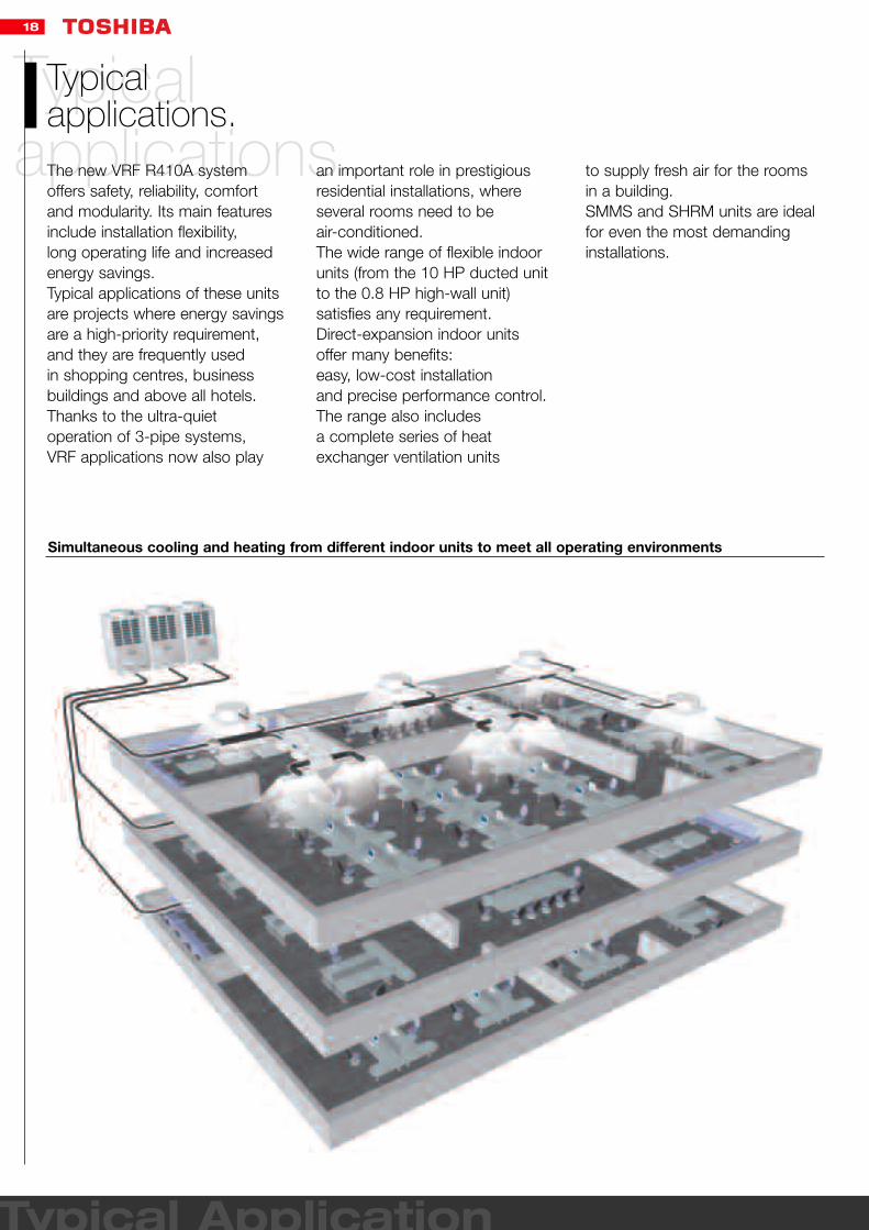
Simultaneous cooling and heating from different indoor units to meet all operating environments
Typical applications.
Typical applications.The new VRF R410A systemoffers safety, reliability, comfortand modularity. Its main featuresinclude installation flexibility, long operating life and increasedenergy savings. Typical applications of these unitsare projects where energy savingsare a high-priority requirement,and they are frequently used in shopping centres, businessbuildings and above all hotels.Thanks to the ultra-quietoperation of 3-pipe systems, VRF applications now also play
an important role in prestigiousresidential installations, whereseveral rooms need to be air-conditioned.The wide range of flexible indoorunits (from the 10 HP ducted unitto the 0.8 HP high-wall unit)satisfies any requirement. Direct-expansion indoor unitsoffer many benefits: easy, low-cost installation and precise performance control.The range also includes a complete series of heatexchanger ventilation units
to supply fresh air for the roomsin a building.SMMS and SHRM units are idealfor even the most demandinginstallations.
Typical Application

19
Shopping centres.Shopping centres.VRF systems offer maximumflexibility. They can be used for even the smallest commercialrooms. The main features includeproviding the required cooling
capacity, easy installation and highest reliability.
Offices.Offices.The air-conditioned area can bedivided into small or largerindividual zones and here too the large choice of indoor units,including cassettes, ducted, floor-mounted and many otherunit types always guarantees the perfect solution.
The system is very efficient and unobtrusive, making VRF an excellent investment!
Hotels.Hotels.In this type of application up to 48 indoor units can be installedin a single refrigerant circuit, and it is possible to reduce the capacity of one or moreindoor units down to theminimum operating limit. This results in considerableenergy savings and ensures a faster payback of theinvestment and optimisedcomfort. The modular design of VRF R410A heat recoverysystems allows installations up to 10.71 kW (30 HP). This system also offers the idealsolution for dual-aspect buildings
that require simultaneous heatingand cooling, leading to furtherenergy savings and making the systems a reliable choice for many prestigious applications.


21
OutdoorOutdoor unitsPanoramic view.
SMMS pag. 22
SHRM pag. 26

22
Business R410A
Dual inverter compressors for each outdoor unit
Design optimised for non-ozone depleting R410A refrigerant
Compatible with Building Management Systems (BMS)
Excellent efficiency (EER and COP)
Maximised flexibility in any application.
Maximised flexibility in any application.Toshiba offers a wide range of outdoor units with 28 models,and 22 different sizes with coolingcapacities from 14 to 135 kW andheating capacities from 16 to 150kW. With the new SMMS, 48units can be connected to a single system. The indoor unit range consists of 10 models and 13 sizes.
This flexibility means that there is always the right system for any requirement.
The new SMMS range:unbeatable performance.
The new SMMS range:unbeatable performance.With the innovative andsophisticated Toshiba technologythe new generation of the R410ASMMS system ensuresextraordinary flexibility in anyapplication.The most advanced heat pumpsystem on the market offers an COP of 4.1 in its 14 kW size.The units are available with
a cooling capacity from 14 to 135kW and a heating capacity from16 to 150 kW, and theirexceptional efficiency permits a reduction of up to 50% in annual energy consumption.

23
SMMS
R410A
DUAL INVERTER SYSTEM
SMMSVRF.
SMMSVRF.Key features
Best COP on the market:(4,1 with 14,4kW size) forreduced energy consumption and increased savings.
Advanced compressor OilManagement System guaranteesimproved reliability.
Interactive Intelligence.
TCC Link: State-of-the-artcommunication bus system withautomatically configuredaddressing.
Up to 48 indoor units can beconnected - Toshiba exclusivity.
Latest Inverter Technology withthe Intelligent Power Drive Unit(IPDU).
Extended pipe runs - 300m - forgreater application flexibility.
Protectiondevices.• Discharge and suction
temperature sensors• Internal overload relay• Compressor overcurrent relay• Overcurrent sensor• High pressure switch• Low pressure sensors
Protectiondevices.

24
MAP0501T8
MAP0501HT8
5 HP
14
3.65
3.84
A
5.85
16
3.84
4.17
A
6.09
20
9000 - 2520
55
-5 - 43°C
-20 - 16°C
1800 x 990 x750
228
Hermetic
8.5
Flare -5/8
Flare - 3/8
Flare - 3/8
175
150
300
40/50
400-3-50
MAP0601T8
MAP0601HT8
6 HP
16
4.64
3.45
A
7.28
18
4.56
3.95
A
7.08
20
9000 - 2520
56
-5 - 43°C
-20 - 16°C
1800 x 990 x750
228
Hermetic
8.5
Brazed - 3/4
Flare - 3/8
Flare - 3/8
175
150
300
40/50
400-3-50
MAP0801T8
MAP0801HT8
8 HP
22.4
5.67
3.95
A
8.62
25
5.88
4.25
A
8.93
30
9000 - 2520
57
-5 - 43°C
-20 - 16°C
1800 x 990 x750
228
Hermetic
12.5
Brazed - 7/8
Flare - 1/2
Flare - 3/8
175
150
300
40/50
400-3-50
MAP1001T8
MAP1001HT8
10 HP
28
7.67
3.65
A
11.55
31.5
7.97
3.95
A
11.98
30
9000 - 2520
58
-5 - 43°C
-20 - 16°C
1800 x 990 x750
228
Hermetic
12.5
Brazed - 7/8
Flare - 1/2
Flare - 3/8
175
150
300
40/50
400-3-50
MAP1201T8
MAP1201HT8
12 HP
33.5
11.92
2.81
C
18.30
37.5
10.19
3.68
A
15.65
30
9000 - 2520
59
-5 - 43°C
-20 - 16°C
1800 x 990 x750
228
Hermetic
12.5
Brazed -1-1/8
Flare - 1/2
Flare - 3/8
175
150
300
40/50
400-3-50
SMMS: Technical specifications heat pumpOutdoor unit CO
HP
Cooling capacity* kW CO
Power input kW CO
EER W/W CO
Energy efficiency class CO
Running current A CO
Heating capacity** kW HP
Power input kW HP
COP W/W HP
Energy efficiency class HP
Running current A HP
Peak demand current*** A
Air Flow m3/h - l/s
Sound pressure level - at 1m dB(A)
Operating range - db °C
Operating range - wb °C
Dimensions (HxWxD) mm
Weight kg
Compressor type
Refrigerant charge R410A kg
Pipework
Suction line type - diameter
Liquid line type - diameter in
Discharge line connection type - diameter in
Maximum equivalent length separation m
Maximum actual piping separation m
Maximum pipe length m
Maximum lift (Indoor unit above/below)**** m
Power supply V-ph-Hz
Business R410A
Model Name
MAP0501HT8
MAP0601HT8
MAP0801HT8
MAP1001HT8
MAP1201HT8
MAP1401HT8
MAP1601HT9
MAP1801HT10
MAP2001HT11
MAP2201HT12
MAP2211HT13
MAP2401HT14
MAP2411HT15
MAP2601HT16
MAP2801HT17
MAP3001HT18
MAP3201HT19
MAP3211HT20
MAP3401HT21
MAP3411HT22
MAP3601HT23
MAP3611HT24
MAP3801HT25
MAP4001HT26
MAP4201HT27
MAP4401HT28
MAP4601HT29
MAP4801HT30
Cooling
capacity
14 kW
16 kW
22.4 kW
28 kW
33.5 kW
38.4 kW
45 kW
50.4 kW
56 kW
61.5 kW
61.5 kW
68 kW
68 kW
73 kW
78.5 kW
84 kW
90 kW
90 kW
96 kW
96 kW
101 kW
101 kW
106.5 kW
112 kW
118 kW
123.5 kW
130 kW
135 kW
Size
5 HP
6 HP
8 HP
10 HP
12 HP
14 HP
16 HP
18 HP
20 HP
22 HP
22 HP
24 HP
24 HP
26 HP
28 HP
30 HP
32 HP
32 HP
34 HP
34 HP
36 HP
36 HP
38 HP
40 HP
42 HP
44 HP
46 HP
48 HP
Heating
capacity
16 kW
18 kW
25 kW
31.5 kW
37.5 kW
43 kW
50 kW
56.5 kW
63 kW
69 kW
69 kW
76.5 kW
76.5 kW
81.5 kW
88 kW
95 kW
100 kW
100 kW
108 kW
108 kW
113 kW
113 kW
119.5 kW
126.5 kW
132 kW
138 kW
145 kW
150 kW
Outdoor units
in combination
1
1
1
1
1
2 (22.4 kW + 16 kW)
2 (22.4 kW + 22.4 kW)
2 (28 kW + 22.4 kW)
2 (28 kW + 28 kW)
3 (22.4 kW + 22.4 kW + 16 kW)
2 (33.5 kW + 28 kW)
3 (22.4 kW + 22.4 kW + 22.4 kW)
2 (33.5 kW + 33.5 kW)
3 (28 kW + 22.4 kW + 22.4 kW)
3 (28 kW + 28 kW + 22.4 kW)
3 (28 kW + 28 kW + 28 kW)
4 (22.4 kW + 22.4 kW + 22.4 kW + 22.4 kW)
3 (33.5 kW + 28 kW + 28 kW)
4 (28 kW + 22.4 kW + 22.4 kW + 22.4 kW)
3 (33.5 kW + 33.5 kW + 28 kW)
4 (28 kW + 28 kW + 22.4 kW + 22.4 kW)
3 (33.5 kW + 33.5 kW + 33.5 kW)
4 (28 kW + 28 kW + 28 kW + 22.4 kW)
4 (28 kW + 28 kW + 28 kW + 28 kW)
4 (33.5 kW + 28 kW + 28 kW + 28 kW)
4 (33.5 kW + 33.5 kW + 28 kW + 28 kW)
4 (33.5 kW + 33.5 kW + 33.5 kW + 28 kW)
4 (33.5 kW + 33.5 kW + 33.5 kW + 33.5 kW)
Number of
indoor units Max
8
10
13
16
20
23
27
30
33
37
37
40
40
43
47
48
48
48
48
48
48
48
48
48
48
48
48
48
* Based on an indoor air temperature of 27°C db/19°C wb and an outdoor air temperature of 35°C db.** Based on an indoor air temperature of 20°C db and an outdoor air temperature of 7°C db/6°C wb.
*** If outdoor units are combined, refer to the installation manual.**** If the height difference between indoor units exceeds 3 m and if the indoor unit is above, max. lift is reduced to 30 m.

25
Model Name
MMU-AP0091HMMU-AP0121HMMU-AP0151HMMU-AP0181HMMU-AP0241HMMU-AP0271HMMU-AP0301HMMU-AP0361HMMU-AP0481HMMU-AP0561H
MMU-AP0071WHMMU-AP0091WHMMU-AP0121WHMMU-AP0151WHMMU-AP0181WHMMU-AP0241WHMMU-AP0271WHMMU-AP0301WHMMU-AP0481WHMMU-AP0071YHMMU-AP0091YHMMU-AP0121YHMMU-AP0151SHMMU-AP0181SHMMU-AP0241SHMMD-AP0071BHMMD-AP0091BHMMD-AP0121BHMMD-AP0151BHMMD-AP0181BHMMD-AP0241BHMMD-AP0271BHMMD-AP0301SHMMD-AP0361BHMMD-AP0481BHMMD-AP0561BHMMD-AP0181HMMD-AP0241HMMD-AP0271HMMD-AP0361HMMD-AP0481HMMD-AP0721HMMD-AP0961H
MMD-AP0071SH/SPHMMD-AP0091SH/SPHMMD-AP0121SH/SPHMMD-AP0151SH/SPHMMD-AP0181SH/SPH
MMC-AP0151HMMC-AP0181HMMC-AP0241HMMC-AP0271HMMC-AP0361HMMC-AP0481HMMK-AP0072HMMK-AP0092HMMK-AP0122H
MMK-AP0071HMMK-AP0091HMMK-AP0121HMMK-AP0151HMMK-AP0181HMMK-AP0241HMML-AP0071HMML-AP0091HMML-AP0121HMML-AP0151HMML-AP0181HMML-AP0241H
MML-AP0071BHMML-AP0091BHMML-AP0121BHMML-AP0151BHMML-AP0181BHMML-AP0241BH
MMF-AP151HMMF-AP181HMMF-AP241HMMF-AP271HMMF-AP361HMMF-AP481HMMF-AP561H
Model Type
4-way Cassette
2-way Cassette
1-Way Cassette
Concealed duct, stand type
Slim Duct
Under-ceiling
High-wall
High-wall
Tall floor-standing
Concealed duct,high static pressure
Floor standingcabinet type
Floor standingConcealed type
CapacityCode
11.251.72
2.53
3.2456
0.81
1.251.72
2.53
3.25
0.81
1.251.72
2.50.81
1.251.72
2.53
3.24562
2.53458100.81
1.251.72
1.72
2.5345
0.81
1.25
0.81
1.251.72
2.50.81
1.251.72
2.50.81
1.251.72
2.51.72
2.53456
Cooling cap.(kW)
2.83.64.55.67.189
11.214162.22.83.64.55.67.189142.22.83.64.55.67.12.22.83.64.55.67.189
11.214165.67.18
11.214
22.4282.22.83.64.55.64.55.67.18
11.2142.22.83.6
2.22.83.64.55.67.12.22.83.64.55.67.12.22.83.64.55.67.14.55.67.18
11.21416
Heating cap.(kW)
3.245
6.38910
12.516182.53.245
6.38910162.53.245
6.38
2.53.245
6.38910
12.516186.389
12.51625
31.52.53.245
6.35
6.389
12.5162.53.24
89.612.815.8
2.53.245
6.38
2.53.245
6.385
6.389
12.51618
Height(mm)
256
319 840 840
22
23
28
33
44
48
830 550
1350
1650 650 52400
655
800
660
1250 155
24
26
21
25
33
645
680
208 11
210
230
220
210
390
850
1100
1200
22
27
31550
700
1000
1350
27
30
39
51
5052
5667
850
12001380
845
910
1180
1595
790
895
1055
1430
18
19
2537
4021
29
48
49
65
950
745
1045
600
398
406235
198
320
380
470
210
210
275
368
630
600
1750
Width(mm)
840
Depth(mm)
840
Weight(kg)
20
SMMS: Technical specifications heat pump

26
Toshiba now offers simultaneousheating and cooling.
Toshiba now offers simultaneousheating and cooling.The new Super Heat RecoveryMulti (SHRM) range introducesimportant innovations with thepossibility to provide simultaneousus heating and cooling. This new model range can satisfythe most demanding needs and offers superior performanceswith COPs of 3.97 (8 HP), 3.61(10 HP) and 3.68 (20/30 HP). The new compact flow selectorthat can be used even inrestricted spaces, enables thesystem to work simultaneously in cooling and heating mode.
The cooling capacity range is from 22.4 to 84 kW and theheating capacity range from 25 to 95 kW. Up to 48 indoor unitscan be connected to a singlesystem.
Business R410A
Dual-inverter compressors for each outdoor unit
Design optimised for non-ozone depleting R410A refrigerant
Low noise level
Excellent efficiency (EER and COP)
Cooling Cooling Cooling Heating
Cooling Heating Cooling Cooling
Flow selector unit

27
SHRM
R410A
DUAL INVERTER SYSTEM
SHRMVRF.
SHRMVRF.Key features
Unbeatable energy consumptionefficiency: average COP of 3.97(22.4 kW).
Top for comfort: cooling orheating is automatically selectedon a unit-by-unit basis to suitlocal area requirements andoperating environment, thanks to the compact flow selector unit.
Toshiba's unique piping branchflexibility: the three-way pipeconnection between indoor and outdoor units accommodatesan installation height variationbetween indoor units of 35 m(equivalent to a 9-story building).
Enviable reliability with the ActiveOil Management system.
Wide control applications: Artificial Intelligence networksystem available and BuildingManagement System (BMS)compatible.
Protectiondevices.• Discharge and suction
temperature sensors• Internal overload relay• Compressor overcurrent relay• Overcurrent sensor• High pressure switch• Low pressure sensors
Protectiondevices.

28
Business R410A
Outdoor unit
hp
Cooling capacity* kW CO
Power input kW CO
EER W/W CO
Energy efficiency class CO
Running current A CO
Heating capacity** kW HP
Power input kW HP
COP W/W HP
Running current A HP
Air Flow m3/h - l/s
Sound pressure level - at 1m dB(A)
Operating range (Cooling)dB(A) °C
Operating range (Heating) wb °C
Dimensions (HxWxD) mm
Weight kg
Compressor type
Refrigerant charge R410A kg
Pipework
Suction gas type -diameter
Liquid type -diameter in
Discharge gas type - diameter in
Maximum equivalent length separation m
Maximum real rength m
Maximum total pipe lengh m
Maximum lift (Indoor unit above/below)*** m
Power supply V-ph-Hz
MMY-MAP0802FT8
8 HP
22.4
6.07
3.69
A
9.25
25.0
6.29
3.97
9.55
9900-2750
57
-10 - 43°C
-20 - 15.5°C
1800 x 990 x 750
263
Hermetic
11,5
Brazed - 7/8
Brazed - 3/4
Flare - 1/2
150
125
300
30/50
400-3-50
MMY-MAP1002FT8
10 HP
28.0
8.54
3.28
B
13.15
31.5
8.73
3.61
13.4
10500-2916
58
-10 - 43°C
-20 - 15.5°C
1800 x 990 x 750
263
Hermetic
11,5
Brazed - 7/8
Brazed - 3/4
Flare - 1/2
150
125
300
30/50
400-3-50
MMY-MAP1202FT8
12 HP
33.5
12.9
2.60
E
19.85
35.5
9.65
3.68
14.85
10500-2916
59
-10 - 43°C
-20 - 15.5°C
1800 x 990 x 750
263
Hermetic
11,5
Brazed - 1 1/8
Brazed - 3/4
Flare - 1/2
150
125
300
30/50
400-3-50
SHRM: Technical specifications heat pump
* Based on an indoor air temperature of 27°C dB(A)/19°C wb and an outdoor air temperature of 35°C dB(A).** Based on an indoor air temperature of 20°C dB(A) and an outdoor air temperature of 7°C dB(A)/6°C wb.*** If the height difference between indoor units exceeds 3 m and if the indoor unit is above, max. lift is reduced to 30 m.
Model Name
MMY-MAP0802FT8
MMY-MAP1002FT8
MMY-MAP1202FT8
MMY-AP1602FT8
MMY-AP1802FT8
MMY-AP2002FT8
MMY-AP2402FT8
MMY-AP2602FT8
MMY-AP2802FT8
MMY-AP3002FT8
Cooling
capacity
22.4 kW
28 kW
33.5 kW
45 kW
50.4 kW
56 kW
68 kW
73 kW
78.5 kW
84 kW
Size
8 HP
10 HP
12 HP
16 HP
18 HP
20 HP
24 HP
26 HP
28 HP
30 HP
Heating
capacity
25 kW
31.5 kW
35.5 kW
50 kW
56.5 kW
63 kW
76.5 kW
81.5 kW
88 kW
95 kW
Outdoor units
in combination
1
1
1
2 (22,4kW+22,4kW)
2 (22,4kW+28,0kW)
2 (28,0kW+28,0kW)
3 (22,4kW+22,4kW+22,4kW)
3 (22,4kW+22,4kW+28,0kW)
3 (22,4kW+28,0kW+28,0kW)
3 (28,0kW+28,0kW+28,0kW)
Number of
indoor units
Max
13
16
16
27
30
33
40
43
47
48
Min
5.6 HP
7.0 HP
8.4 HP
11.2 HP
21.0 HP
14.0 HP
16.8 HP
18.2 HP
19.6 HP
21.0 HP
Max
10.8 HP
13.5 HP
14.4 HP
21.6 HP
40.5 HP
27.0 HP
32.4 HP
35.1 HP
37.8 HP
40.5 HP
SHRM: Technical specifications heat pumpTotal cap.of connectable
indoor units

29
Model Name
MMU-AP0091HMMU-AP0121HMMU-AP0151HMMU-AP0181HMMU-AP0241HMMU-AP0271HMMU-AP0301HMMU-AP0361HMMU-AP0481HMMU-AP0561H
MMU-AP0071WHMMU-AP0091WHMMU-AP0121WHMMU-AP0151WHMMU-AP0181WHMMU-AP0241WHMMU-AP0271WHMMU-AP0301WHMMU-AP0481WHMMU-AP0071YHMMU-AP0091YHMMU-AP0121YHMMU-AP0151SHMMU-AP0181SHMMU-AP0241SHMMD-AP0071BHMMD-AP0091BHMMD-AP0121BHMMD-AP0151BHMMD-AP0181BHMMD-AP0241BHMMD-AP0271BHMMD-AP0301SHMMD-AP0361BHMMD-AP0481BHMMD-AP0561BHMMD-AP0181HMMD-AP0241HMMD-AP0271HMMD-AP0361HMMD-AP0481HMMD-AP0721HMMD-AP0961H
MMD-AP0071SH/SPHMMD-AP0091SH/SPHMMD-AP0121SH/SPHMMD-AP0151SH/SPHMMD-AP0181SH/SPH
MMC-AP0151HMMC-AP0181HMMC-AP0241HMMC-AP0271HMMC-AP0361HMMC-AP0481HMMK-AP0072HMMK-AP0092HMMK-AP0122H
MMK-AP0071HMMK-AP0091HMMK-AP0121HMMK-AP0151HMMK-AP0181HMMK-AP0241HMML-AP0071HMML-AP0091HMML-AP0121HMML-AP0151HMML-AP0181HMML-AP0241H
MML-AP0071BHMML-AP0091BHMML-AP0121BHMML-AP0151BHMML-AP0181BHMML-AP0241BH
MMF-AP151HMMF-AP181HMMF-AP241HMMF-AP271HMMF-AP361HMMF-AP481HMMF-AP561H
Model Type
4-Way Cassette
2-Way Cassette
1-Way Cassette
Concealed duct, stand type
Slim Duct
Under-ceiling
High-wall
High-wall
Tall floor-standing
Concealed duct,high static pressure
Floor standingcabinet type
Floor standingConcealed type
CapacityCode
11.251.72
2.53
3.2456
0.81
1.251.72
2.53
3.25
0.81
1.251.72
2.50.81
1.251.72
2.53
3.24562
2.53458100.81
1.251.72
1.72
2.5345
0.81
1.25
0.81
1.251.72
2.50.81
1.251.72
2.50.81
1.251.72
2.51.72
2.53456
Cooling cap.(kW)
2.83.64.55.67.189
11.214162.22.83.64.55.67.189142.22.83.64.55.67.12.22.83.64.55.67.189
11.214165.67.18
11.214
22.4282.22.83.64.55.64.55.67.18
11.2142.22.83.6
2.22.83.64.55.67.12.22.83.64.55.67.12.22.83.64.55.67.14.55.67.18
11.21416
Heating cap.(kW)
3.245
6.38910
12.516182.53.245
6.38910162.53.245
6.38
2.53.245
6.38910
12.516186.389
12.51625
31.52.53.245
6.35
6.389
12.5162.53.24
89.612.815.8
2.53.245
6.38
2.53.245
6.385
6.389
12.51618
Height(mm)
256
319 840 840
22
23
28
33
44
48
830 550
1350
1650 650 52400
655
800
660
1250 155
24
26
21
25
33
645
680
208 11
210
230
220
210
390
850
1100
1200
22
27
31550
700
1000
1350
27
30
39
51
5052
5667
850
12001380
845
910
1180
1595
790
895
1055
1430
18
19
2537
4021
29
48
49
65
950
745
1045
600
398
406235
198
320
380
470
210
210
275
368
630
600
1750
Width(mm)
840
Depth(mm)
840
Weight(kg)
20
SHRM: Technical specifications heat pump

31
IndoorIndoor UnitsPanoramic view.
4 Way Cassette pag. 34
2 Way Cassette pag. 35
1 Way Cassette pag. 36
Standard Ducted pag. 37
New Slim Duct pag. 38
High Static Pressure Ducted Unit pag. 39
Ceiling Suspended pag. 40
New Compact High Wall pag. 41
High Wall pag. 42
Floor Mounted Console pag. 43
Concealed Chassis pag. 44
Floor Standing pag. 45
Air-to-Air Heat Exchangers pag. 46

Ind
oo
r
Complete range of indoor units.
Complete range of indoor units.The large choice of indoor unitmodels and sizes for the newR410A VRF range makes itideal for any type if installation,meeting space, aesthetic and functional requirements.The performances of all unitsare maximised - lowest soundlevels, optimised air flows and the extremely compactdesign are the key features of the Toshiba units.
The latest additions to the range,the new compact hi-wall and theslim duct units, reaffirm Toshiba'scommitment to create the perfectclimate and well-being for business users. Toshibaprovides not only comfort, but also the ideal climateconditions for any application.

33
Model Name
MMU-AP0091HMMU-AP0121HMMU-AP0151HMMU-AP0181HMMU-AP0241HMMU-AP0271HMMU-AP0301HMMU-AP0361HMMU-AP0481HMMU-AP0561H
MMU-AP0071WHMMU-AP0091WHMMU-AP0121WHMMU-AP0151WHMMU-AP0181WHMMU-AP0241WHMMU-AP0271WHMMU-AP0301WHMMU-AP0481WHMMU-AP0071YHMMU-AP0091YHMMU-AP0121YHMMU-AP0151SHMMU-AP0181SHMMU-AP0241SHMMD-AP0071BHMMD-AP0091BHMMD-AP0121BHMMD-AP0151BHMMD-AP0181BHMMD-AP0241BHMMD-AP0271BHMMD-AP0301SHMMD-AP0361BHMMD-AP0481BHMMD-AP0561BHMMD-AP0181HMMD-AP0241HMMD-AP0271HMMD-AP0361HMMD-AP0481HMMD-AP0721HMMD-AP0961H
MMD-AP0071SH/SPHMMD-AP0091SH/SPHMMD-AP0121SH/SPHMMD-AP0151SH/SPHMMD-AP0181SH/SPH
MMC-AP0151HMMC-AP0181HMMC-AP0241HMMC-AP0271HMMC-AP0361HMMC-AP0481HMMK-AP0072HMMK-AP0092HMMK-AP0122H
MMK-AP0071HMMK-AP0091HMMK-AP0121HMMK-AP0151HMMK-AP0181HMMK-AP0241HMML-AP0071HMML-AP0091HMML-AP0121HMML-AP0151HMML-AP0181HMML-AP0241H
MML-AP0071BHMML-AP0091BHMML-AP0121BHMML-AP0151BHMML-AP0181BHMML-AP0241BH
MMF-AP151HMMF-AP181HMMF-AP241HMMF-AP271HMMF-AP361HMMF-AP481HMMF-AP561H
Model Type
4-Way Cassette
2-Way Cassette
1-Way Cassette
Concealed duct, stand type
Slim Duct
Under-ceiling
High-wall
High-wall
Tall floor-standing
Concealed duct,high static pressure
Floor standingcabinet type
Floor standingConcealed type
CapacityCode
11.251.72
2.53
3.2456
0.81
1.251.72
2.53
3.25
0.81
1.251.72
2.50.81
1.251.72
2.53
3.24562
2.53458100.81
1.251.72
1.72
2.5345
0.81
1.25
0.81
1.251.72
2.50.81
1.251.72
2.50.81
1.251.72
2.51.72
2.53456
Cooling cap.(kW)
2.83.64.55.67.189
11.214162.22.83.64.55.67.189142.22.83.64.55.67.12.22.83.64.55.67.189
11.214165.67.18
11.214
22.4282.22.83.64.55.64.55.67.18
11.2142.22.83.6
2.22.83.64.55.67.12.22.83.64.55.67.12.22.83.64.55.67.14.55.67.18
11.21416
Heating cap.(kW)
3.245
6.38910
12.516182.53.245
6.38910162.53.245
6.38
2.53.245
6.38910
12.516186.389
12.51625
31.52.53.245
6.35
6.389
12.5162.53.24
89.612.815.8
2.53.245
6.38
2.53.245
6.385
6.389
12.51618
Height(mm)
256
319 840 840
22
23
28
33
44
48
830 550
1350
1650 650 52400
655
800
660
1250 155
24
26
21
25
33
645
680
208 11
210
230
220
210
390
850
1100
1200
22
27
31550
700
1000
1350
27
30
39
51
5052
5667
850
12001380
845
910
1180
1595
790
895
1055
1430
18
19
2537
4021
29
48
49
65
950
745
1045
600
398
406235
198
320
380
470
210
210
275
368
630
600
1750
Width(mm)
840
Depth(mm)
840
Weight(kg)
20
Technical specifications heat pump

34
AP0271H
256 x 840 x 840
23
35 x 950 x 950
4.5
5/8
3/8
25
220/240-1-50
MMU-AP (...) H
Indoor unit
Cooling capacity kW
Cooling capacity Frig/h
Heating capacity kW
Heating capacity Frig/h
Power consumption kW
Running current A
Starting current A
MMU-
CO
CO
HP
HP
AP0091H
2.8
2408
3.2
2752
0.02
0.17
0.3
0.032
0.24
0.42
AP0121H
3.6
3096
4
3440
AP0151H
4.5
3870
5
4300
0.022
0.19
0.33
AP0181H
5.6
4816
6.3
4816
0.026
0.21
0.36
AP0241H
7.1
6106
8
6106
AP0271H
8
6880
9
6880
AP0301H
9
7740
10
7740
0.048
0.35
0.59
AP0361H
11.2
9632
12.5
9632
0.07
0.59
0.87
AP0481H
14
12040
16
12040
0.11
0.81
1.23
AP0561H
16
13760
18
13760
0.112
0.83
1.26
Indoor unit
Air Flow (h/l) m3/h
Air Flow (h/l) l/s
Sound pressure level (h/l) dB(A)
Dimensions (HxWxD) mm
Weight kg
Panel dimensions (HxWxD) mm
Panel weight kg
Connecting pipe
Gas in
Liquid in
Drain port diameter mm
Power supply V-ph-Hz
Business R410A
4 Way CassetteSMMS and SHRM.
4 Way CassetteSMMS and SHRM.Features
This 4-Way cassette benefitsfrom Toshiba state-of-the-artenergy saving technology: With the industry’s mostadvanced high-lift drain pipeprovided as a standard, it offersthe ideal solution for smallcommercial applications wherespace is limited. Unobtrusiveand flexible, this unit blends inwith any room interior décorand is ideal for both new andrefurbishment projects.
Key features
Clean Ceiling: the innovative air flowcontrol and the new panel designprevent dust from accumulatingaround the air outlet of the ceiling.
Clean unit: both the louvre and the grille are easily detachable and washable.
Flexible installation: ideal for siteswith restriction on the space aboveceiling level, the unit features ahigh-lift drain pipe (850 mm).
Easy maintenance: Corner pocketsin all four panel corners allowconvenient access to the adjustmentcontrols behind the panel.
Simplified multidrop wiringconnections.
MMU- AP0091H AP0121H AP0151H
930/780
258/217
31/27
AP0181H
1050/800
292/222
32/28
AP0241H
1200/820
333/278
34/28
AP0301H
1320/850
367/236
37/30
AP0361H
1680/1070
467/297
40/33
Technical specifications heat pump
800/680
222/189
30/27
256 x 840 x 840
20
35 x 950 x 950
4.5
3/8
1/4
25
220/240-1-50
256 x 840 x 840
22
35 x 950 x 950
4.5
1/2
1/4
25
220/240-1-50
AP0271H AP0481H
2040/1130
567/314
44/34
319 x 840 x 840
28
35 x 950 x 950
4.5
5/8
3/8
25
220/240-1-50
AP0561H
2090/1230
580/342
45/34

35
2 Way CassetteSMMS and SHRM.
2 Way CassetteSMMS and SHRM.Features
With its very compact size, this2-Way Cassette is the bestsolution for small rooms.Discreet and slim, it can beeasily installed and fits anyinterior decor. In addition,thanks to its silent operation,this model creates a verypleasant, quiet and comfortableenvironment.
Key features
Slim design, with a 8 mm highceiling panel.
Low noise level: it operates atonly 30 dB(A) (sizes 2.2 to 5.6kW).
Unique Air flow control: the aircurrent is balanced between 2directions, for a maximisedcomfort.
Flexible installation: thecondensate drain pump raisesdrain piping up to 500 mm.
Enhanced Indoor Air Quality:- Standard long-life filters.- Fresh air intake: ensures - constant air renewal.
Indoor unit
Cooling capacity kW
Cooling capacity Frig/h
Heating capacity kW
Heating capacity Frig/h
Power consumption kW
Running current A
Starting current A
MMU-
CO
CO
HP
HP
AP0071WH
2.2
1892
2.5
2150
AP0091WH
2.8
2408
3.2
2752
0.07
0.31
0.47
AP0121WH
3.6
3096
4
3096
AP0151WH
4.5
3870
5
4300
0.072
0.32
0.6
AP0181WH
5.6
4816
6.3
5418
AP0241WH
7.1
6106
8
6880
0.105
0.46
0.89
AP0271WH
8
6880
9
7740
AP0301WH
9
7740
10
8600
0.106
0.47
0.98
Indoor unit
Air Flow (h/l) m3/h
Air Flow (h/l) l/s
Sound pressure level (h/l) dB(A)
Dimensions (HxWxD) mm
Weight kg
Panel dimensions (HxWxD) mm
Panel weight kg
Connecting pipe
Gas in
Liquid in
Drain port diameter mm
Power supply V-ph-Hz
MMU- AP0071WH AP0091WH
570/450
158/125
34/30
398 x 830 x 550
33
8 x 1000 x 650
8
3/8
1/4
25
220/240-1-50
AP0121WH AP0151WH
780/600
217/167
35/30
398 x 1350 x 550
44
8 x 1520 x 650
11
1/2
1/4
25
220/240-1-50
1140/720
317/200
38/33
AP0181WH AP0241WH AP0271WH
398 x 1350 x 550
48
8 x 1520 x 650
11
5/8
3/8
25
220/240-1-50
AP0301WH
1260/960
350/267
40/34
Technical specifications heat pump
MMU-AP (...) WH

36
Business R410A
1 Way CassetteSMMS and SHRM.
1 Way CassetteSMMS and SHRM.Features
Toshiba’s innovative slim-line 1-Way Cassette is simple toinstall and is suitable for smallareas, such as hotels or officesguestrooms and receptionrooms.
Key features
Compact hi-tech design: 235 x850 x 400 mm (sizes 2.2 to 3.6).
Flexible installation: ideal for siteswith restriction on the spaceabove ceiling level, the unitfeatures a high-lift drain pipe (350 mm).
Low noise level: it operates atonly 34 dB(A) (sizes 2.2 to 3.6).
Indoor unit
Cooling capacity kW
Cooling capacity Frig/h
Heating capacity kW
Heating capacity Frig/h
Power consumption kW
Running current A
Starting current A
MMU-
CO
CO
HP
HP
AP0071YH
2.2
1892
2.5
2150
AP0091YH
2.8
2408
3.2
2752
0.053
0.24
0.6
AP0121YH
3.6
3096
4
3440
AP0151SH
4.5
3870
5
4300
0.103
0.48
0.8
AP0181SH
5.6
4816
6.3
5418
AP0241SH
7.1
6106
8
6880
0.115
0.55
1.1
Indoor unit
Air Flow (h/l) m3/h
Air Flow (h/l) l/s
Sound pressure level (h/l) dB(A)
Dimensions (HxWxD) mm
Weight kg
Panel dimensions (HxWxD) mm
Panel weight kg
Connecting pipe
Gas in
Liquid in
Drain port diameter mm
Power supply V-ph-Hz
MMU- AP0071YH AP0091YH
540/420
150/117
42/34
235 x 850 x 400
22
18 x 1050 x 470
3.5
3/8
1/4
25
220/240-1-50
AP0121YH AP0151SH
198 x 1000 x 655
27
10 x 1220 x 755
8
1/2
1/4
25
220/240-1-50
AP0181SH
780/660
217/183
42/35
AP0241SH
198 x 1200 x 655
31
10 x 1420 x 755
9
5/8
3/8
25
220/240-1-50
Technical specifications heat pump
MMU-AP (...) YH/SH

37
Standard Ducted UnitSMMS and SHRM.
Standard Ducted UnitSMMS and SHRM.Features
The discreet standard ductedunit can be easily installed inany ceiling voids or falseceilings, and operates verysilently.Whatever the shape of theroom, this flexible modelensures a uniform temperatureand air distribution, andenhances the Indoor Air Qualityof the room, for an optimumuser comfort.
Key features
Space-saving design: only 320mm in height.
Low noise level: at the low fanspeed mode, it operates at only26 dB(A).
Flexible installation: ideal for siteswith restriction on the spaceabove ceiling level, the unitfeatures a high-lift drain pipe(270mm).
Uniform air distribution.
Enhanced Indoor Air Quality:- Wide range of filters.- Fresh air intake: ensures aconstant air renewal.
Indoor unit
Cooling capacity kW
Cooling capacity Frig/h
Heating capacity kW
Heating capacity Frig/h
Power consumption kW
Running current A
Starting current A
MMD-
CO
CO
HP
HP
AP0071BH
2.2
1892
2.5
2150
0.033
0.29
0.5
480/340
133/64
30/26
0.039
0.34
0.59
0.06
0.52
0.9
0.128
0.98
1.7
AP0091BH
2.8
2408
3.2
2752
AP0121BH
3.6
3096
4
34400
AP0151BH
4.5
3870
5
4300
AP0181BH
5.6
4816
6.3
5418
0.05
0.43
0.75
AP0241BH
7.1
6106
8
6880
AP0271BH
8
6880
9
7740
AP0361BH
11.2
9632
12.5
10750
0.107
0.83
1.44
AP0481BH
14
12040
16
13760
AP0561BH
16
13760
18
15480
Indoor unit
Air Flow (h/l) m3/h
Air Flow (h/l) l/s
Sound pressure level (h/l) dB(A)
Dimensions (HxWxD) mm
Weight kg
Panel dimensions (HxWxD) mm
Panel weight kg
External static pressure Pa
Connecting pipe
Gas in
Liquid in
Drain port diameter mm
Power supply V-ph-Hz
AP0301BH
9
7740
10
8600
0.071
0.61
1.05
MMD- AP0071BH AP0091BH
320 x 550 x 800
28
9 x 630 x 500
3.5
3/8
1/4
25
220/240-1-50
AP0121BH
570/400
158/111
31/27
AP0151BH
650/480
180/133
320 x 700 x 800
32
9 x 780 x 500
4
AP0181BH
780/540
217/150
32/28
1/2
1/4
25
220/240-1-50
AP0241BH
1140/870
317/242
33/29
AP0271BH
320 x 1000 x 800
43
9 x 1080 x 500
6
AP0301BH
1260/870
350/242
34/29
5/8
3/8
25
220/240-1-50
AP0361BH
1620/1200
450/333
36/32
1980/1490
550/414
38/32
AP0481BH
320 x 1350 x 800
55
9 x 1430 x 500
7
5/8
3/8
25
220/240-1-50
AP0561BH
Technical specifications heat pump
MMD-AP (...) BH
38
Business R410A
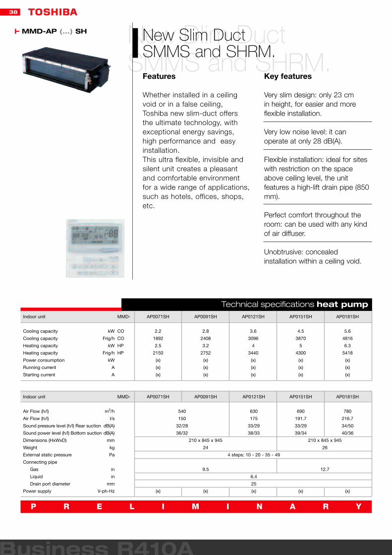
New Dlim DuctSMMS and SHRM.
New Slim DuctSMMS and SHRM.Features
Whether installed in a ceilingvoid or in a false ceiling,Toshiba new slim-duct offersthe ultimate technology, withexceptional energy savings,high performance and easyinstallation.This ultra flexible, invisible andsilent unit creates a pleasantand comfortable environmentfor a wide range of applications,such as hotels, offices, shops,etc.
Key features
Very slim design: only 23 cm in height, for easier and moreflexible installation.
Very low noise level: it canoperate at only 28 dB(A).
Flexible installation: ideal for siteswith restriction on the spaceabove ceiling level, the unitfeatures a high-lift drain pipe (850mm).
Perfect comfort throughout theroom: can be used with any kindof air diffuser.
Unobtrusive: concealedinstallation within a ceiling void.
Indoor unit
Cooling capacity kW
Cooling capacity Frig/h
Heating capacity kW
Heating capacity Frig/h
Power consumption kW
Running current A
Starting current A
MMD-
CO
CO
HP
HP
AP0071SH
2.2
1892
2.5
2150
(x)
(x)
(x)
AP0091SH
2.8
2408
3.2
2752
(x)
(x)
(x)
AP0121SH
3.6
3096
4
3440
(x)
(x)
(x)
AP0151SH
4.5
3870
5
4300
(x)
(x)
(x)
AP0181SH
5.6
4816
6.3
5418
(x)
(x)
(x)
Indoor unit
Air Flow (h/l) m3/h
Air Flow (h/l) l/s
Sound pressure level (h/l) Rear suction dB(A)
Sound power level (h/l) Bottom suction dB(A)
Dimensions (HxWxD) mm
Weight kg
External static pressure Pa
Connecting pipe
Gas in
Liquid in
Drain port diameter mm
Power supply V-ph-Hz
MMD- AP0071SH
(x)
AP0091SH
210 x 845 x 945
24
9.5
(x)
210 x 845 x 945
26
12.7
AP0121SH
630
175
33/29
38/33
4 steps: 10 - 20 - 35 - 49
6.4
25
(x)
540
150
32/28
36/32
AP0151SH
690
191.7
33/29
39/34
(x)
AP0181SH
780
216.7
34/50
40/36
(x)
Technical specifications heat pump
MMD-AP (...) SH
P R E L I M I N A R Y

39
High Static Pressure Ducted unitSMMS and SHRM.
High Static Pressure Ducted UnitSMMS and SHRM.Features
With a maximum Air Flow ofaround 2000 m3/h, this high-pressure ducted unit isToshiba’s most powerful ductunit. Unobtrusive, flexible andcompact, it can be installedeasily, and fits perfectly to anyinterior decor or design.This model is the ideal solutionfor both new and restoredbuildings.
Key features
Easy installation.
Inspection hole enables easyaccess and maintenance.
Wide range of options available:vaporizing humidifiers, long-lifefilters, etc.
Static pressure can be set to 3levels (68.6, 137 and 196 Pa)
Indoor unit
Cooling capacity kW
Cooling capacity Frig/h
Heating capacity kW
Heating capacity Frig/h
Power consumption kW
Running current A
Starting current A
MMD-
CO
CO
HP
HP
AP0181H
5.6
4816
6.3
5418
0.184
0.81
1.3
AP0241H
7.1
6106
8
6880
0.299
1.35
3.5
AP0271H
8
6880
9
7740
AP0361H
11.2
9632
12.5
10750
0.368
1.63
4.1
AP0481H
14
12040
16
13760
0.414
1.84
4.8
AP0721H
22.4
19264
25
21500
1.2
5.25
13.6
AP0961H
28
24080
31.5
27090
1.26
5.52
14.8
Indoor unit
Air Flow (h/l) m3/h
Air Flow (h/l) l/s
Sound pressure level (h/l) dB(A)
Dimensions (HxWxD) mm
Weight kg
External static pressure Pa
Connecting pipe
Gas in
Liquid in
Drain port diameter mm
Power supply V-ph-Hz
MMD- AP0181H
1080/720
300/200
37
50
1/2
1/4
25
220/240-1-50
1580/1060
439/295
380 x 850 x660
52
AP0241H
40
AP0271H
5/8
3/8
25
220/240-1-50
AP0361H
1920/1280
533/355
56
3 steps: 68.6 - 137 - 196
AP0481H
2520/1680
700/467
380 x 1200 x 660
67
5/8
3/8
25
220/240-1-50
AP0721H
4320/2880
1200/800
49
470 x 1380 x 1250
150
7/8
1/2
25
220/240-1-50
AP0961H
5040/3360
1400/933
50
Technical specifications heat pump
MMD-AP (...) BH

40
Business R410A
Ceiling Suspended UnitSMMS and SHRM.
Ceiling Suspended UnitSMMS and SHRM.Features
Thanks to its simplesuspension, the installation ofthis ceiling suspended unit isvery easy. Moreover, this modelcreates a very pleasant andrelaxing environment, diffusingautomatically, rapidly anduniformly the requiredtemperature, in cooling andheating modes.Best solution for fixed ceilings,it can be used for a wide rangeof applications, but isparticularly recommended forrefurbishment projects.
Key features
Easy and fast installation:simplified unit suspension.
Space-saving unit: Ideal for siteswith restriction on the spaceabove ceiling level, the unitfeatures a high-lift drain pipe (600mm).
Optimum louvre control: air flowangle is automatically set to themost suitable setting according toyour cooling or heating needs,and an automatic swing modeenables air flow to reach all areaof the room.
Piping flexibility:- Refrigerant piping: 3 possibilities(top, rear or right side of the unit).- Drain piping: 2 possibilities
Indoor unit
Cooling capacity kW
Cooling capacity Frig/h
Heating capacity kW
Heating capacity Frig/h
Power consumption kW
Running current A
Starting current A
MMC-
CO
CO
HP
HP
AP0151H
4.5
3870
5
4300
0.033
0.29
0.43
AP0181H
5.6
4816
6.3
5418
0.038
0.32
0.48
AP0241H
7.1
6106
8
6880
0.05
0.42
0.62
AP0271H
8
6880
9
7740
AP0361H
11.2
9632
12.5
10750
0.091
0.78
1.17
AP0481H
14
12040
16
13760
0.11
0.84
1.25
Indoor unit
Air Flow (h/l) m3/h
Air Flow (h/l) l/s
Sound pressure level (h/l) dB(A)
Dimensions (HxWxD) mm
Weight kg
Connecting pipe
Gas in
Liquid in
Drain port diameter mm
Power supply V-ph-Hz
MMC- AP0151H
720/540
200/150
35/30
210 x 910 x 680
22
1/2
1/4
20
220/240-1-50
210 x 1595 x 680
34
5/8
3/8
20
220/240-1-50
AP0181H
780/540
217/150
36/30
AP0241H AP0271H
1110/840
308/233
38/33
210 x 1180 x 680
26
5/8
3/8
20
220/240-1-50
AP0361H
1650/1200
458/333
41/35
AP0481H
1800/1320
500/367
43/37
Technical specifications heat pump
MMC-AP (...) H

41
New Compact High WallSMMS and SHRM.
New Compact High WallSMMS and SHRM.Features
Toshiba is proud to launch the new compact and light High Wall for the SHRM and SMMS range. In addition to its enhanceddesign, this silent unit benefitsfrom capacity control at allconditions.
Key features
New compact and moderndesign: - Only 45 litres volume, the bestin its class.- New rounded shape and grille,for a more attractive design.
Lighter unit:11kg - reduced by40% less than average equivalentunits compared to the previousmodel.
Clean unit: the panel is easilydetachable for fast grille andfilters cleaning.
Low noise level: it operates atonly 29 dB(A).
Auto-swing mechanism.
Indoor unit
Cooling capacity kW
Cooling capacity Frig/h
Heating capacity kW
Heating capacity Frig/h
Power consumption kW
Running current A
Starting current A
MMK-
CO
CO
HP
HP
AP0072H
2.2
1892
2.5
2150
0.017
0.17
0.22
AP0092H
2.8
2408
3.2
2752
0.018
0.18
0.23
AP0121H
3.6
3096
4
3440
0.019
0.19
0.24
Indoor unit
Air Flow (h/l) m3/h
Air Flow (h/l) l/s
Sound pressure level (h/l) dB(A)
Dimensions (HxWxD) mm
Weight kg
Connecting pipe
Gas in
Liquid in
Drain port diameter mm
Power supply V-ph-Hz
MMK- AP0071H
480/360
133/100
35/29
275 x 790 x 208
11
3/8
1/4
17
220/240-1-50
AP0091H
510/360
142/100
36/29
276 x 790 x 208
12
3/9
1/5
17
220/240-1-50
AP0121H
540/360
150/100
37/29
277 x 790 x 208
13
3/10
1/6
17
220/240-1-50
Technical specifications heat pump
MMK-AP (...) H

42
Business R410A
High Wall unitSMMS and SHRM.
High Wall unitSMMS and SHRM.Features
Toshiba High Wall is elegantand slim, to blend in with anyinterior decor.
Key features
Aesthetic and compact design:- Elegant, with its soft whitecolour and round design.- Depth: only 210 mm, for aninstallation along the wall withoutwasting valuable floor space.
Easy installation, with its auxiliarypiping.
Piping flexibility:- Refrigerant piping: 3 possibilities(top, rear or right side of the unit).
Top for comfort: 70° directionalauto-swing louver for optimum airdistribution.
Indoor unit
Cooling capacity kW
Cooling capacity Frig/h
Heating capacity kW
Heating capacity Frig/h
Power consumption kW
Running current A
Starting current A
MMK-
CO
CO
HP
HP
AP0071H
2.2
1892
2.5
2150
AP0091H
2.8
2408
3.2
2752
AP0121H
3.6
3096
4
3440
AP0151H
4.5
3870
5
4300
AP0181H
5.6
4816
6.3
5418
0.056
0.26
0.6
0.092
0.43
0.8
0.102
0.47
1.1
AP0241H
7.1
6106
8
6880
Indoor unit
Air Flow (h/l) m3/h
Air Flow (h/l) l/s
Sound pressure level (h/l) dB(A)
Dimensions (HxWxD) mm
Weight kg
Connecting pipe
Gas in
Liquid in
Drain port diameter mm
Power supply V-ph-Hz
MMK- AP0071H AP0091H
3/8
1/4
20
220/240-1-50
480/360
133/100
39/35
630 x 950 x 230
37
AP0121H AP0151H
900/650
250/180
45/38
630 x 950 x 230
37
AP0181H
1/2
1/4
20
220/240-1-50
1080/780
300/217
49/39
630 x 950 x 230
40
AP0241H
5/8
3/8
20
220/240-1-50
Technical specifications heat pump
MMK-AP (...) H

43
Floor Mounted ConsoleSMMS and SHRM.
Floor Mounted ConsoleSMMS and SHRM.Features
Suitable for refurbishmentprojects of small spaces.
Key features
Optimum piping flexibility:- Refrigerant piping: 4 possibilities(top, rear, left or right side of theunit).- Drain piping: 4 possibilities (top,rear, left or right side of the unit).
Top for comfort: Air distributioncan be easily reversed to meetthe occupant’s preference.
Wide choice of installationsettings.
Compact unit : 630 x 950 x 230mm, for more flexible installationsand valuable space savings.
Indoor unit
Cooling capacity kW
Cooling capacity Frig/h
Heating capacity kW
Heating capacity Frig/h
Power consumption kW
Running current A
Starting current A
MML-
CO
CO
HP
HP
AP0071BH
2.2
1892
2.5
2150
AP0091BH
2.8
2408
3.2
2752
0.056
0.25
0.6
AP0121BH
3.6
3096
4
3440
AP0151BH
4.5
3870
5
4300
0.09
0.45
0.8
AP0181BH
5.6
4816
6.3
5418
AP0241BH
7.1
6106
8
6880
0.095
0.46
1
Indoor unit
Air Flow (h/l) m3/h
Air Flow (h/l) l/s
Sound pressure level (h/l) dB(A)
Dimensions (HxWxD) mm
Weight kg
Connecting pipe
Gas in
Liquid in
Drain port diameter mm
Power supply V-ph-Hz
MML- AP0071BH AP0091BH
460/300
128/83
36/32
600 X 745 X 220
21
3/8
1/4
20
220/240-1-50
AP0121BH AP0151BH AP0181BH
600 X 1045 X 220
29
740/490
205/136
36/32
1/2
1/4
20
220/240-1-50
AP0241BH
950/640
264/178
42/33
5/8
3/8
20
220/240-1-50
Technical specifications heat pump
MML-AP (...) H

44
Business R410A
Concealed Chassis UnitSMMS and SHRM.
Concealed Chassis UnitSMMS and SHRM.Features
Toshiba’s concealed chassis isthe perfect solution forperimeter walls and can behidden behind a decorativepanel to blend with any roominterior.Ideal for office and othercommercial buildings with largefluctuation in load, the unit fitsperfectly specialist applicationssuch as libraries, hospitals, etc.
Key features
Very compact design:- Height: only 600 mm, ideal forperimeters walls.- Depth: 200 mm, the unit can beinstalled along the wall withoutwasting valuable floor space.
Low noise level: it operates atonly 32 dB(A).
Easy maintenance:- Removable split front panel.- Easy access to the drain pan onthe right side of the unit.
Indoor unit
Cooling capacity kW
Cooling capacity Frig/h
Heating capacity kW
Heating capacity Frig/h
Power consumption kW
Running current A
Starting current A
MML-
CO
CO
HP
HP
AP0071H
2.2
1892
2.5
2150
AP0091H
2.8
2408
3.2
2752
0.035
0.3
0.36
AP0121H
3.6
3096
4
3440
AP0151H
4.5
3870
5
4300
AP0181H
5.6
4816
6.3
5418
AP0241H
7.1
6106
8
6880
0.04
0.35
0.47
0.037
0.32
0.42
Indoor unit
Air Flow (h/l) m3/h
Air Flow (h/l) l/s
Sound pressure level (h/l) dB(A)
Dimensions (HxWxD) mm
Weight kg
Connecting pipe
Gas in
Liquid in
Drain port diameter mm
Power supply V-ph-Hz
MML- AP0071H AP0091H
600/480
167/133
39/31
368 x 895 x 210
18
3/8
1/4
20
220/240-1-50
AP0121H AP0151H AP0181H AP0241H
1200/900
333/250
42/35
368 x 1430 x 210
25
5/8
3/8
20
220/240-1-50
780/600
217/167
42/35
368 x 1055 x 210
19
1/2
1/4
20
220/240-1-50
Technical specifications heat pump
MML-AP (...) BH

45
Floor StandingSMMS and SHRM.
Floor StandingSMMS and SHRM.Features
This system is particularlysuitable to air condition largerooms that are not very high. It is also the right solution for small, low areas such as restaurants or lofts. The units offer high air flowrates and superior air throwvalues. Their wide airdistribution angle permits airconditioning of even largerooms.
Key features
Reduced footprint- Two sizes, 0.128 m2 up to 8 kWand 0.243 m2 up to 16 kW.
High air flows- From 180 l/s to 600 l/s (660m3/h to 2160 m3/h).
Wide air distribution angle- Up to 150°.
Large capacity range- Cooling capacities from 4.5 kWto 16 kW and heating capacitiesfrom 5 kW to 18 kW.
Indoor unit
Cooling capacity kW
Cooling capacity Frig/h
Heating capacity kW
Heating capacity Frig/h
Power consumption kW
Running current A
Starting current A
MMF-
CO
CO
HP
HP
AP0151H
4.5
3870
5
4300
AP0181H
5.6
4816
6.3
5418
AP0241H
7.1
6106
8
6880
AP0271H
8
6880
9
7740
AP0361H
11.2
9632
12.5
10750
0.28
1.29
1.7
AP0481H
14
12040
16
13760
AP0561H
16
13760
18
15480
0.35
1.6
2.1
0.19
0.88
1.1
0.15
0.67
0.9
Indoor unit
Air Flow (h/l) m3/h
Air Flow (h/l) l/s
Sound pressure level (h/l) dB(A)
Dimensions (HxWxD) mm
Weight kg
Connecting pipe
Gas in
Liquid in
Drain port diameter mm
Power supply V-ph-Hz
MMF- AP0151H
1/2
1/4
20
220/240-1-50
AP0181H AP0241H
5/8
3/8
20
220/240-1-50
900/660
250/183
46/38
1750 x 600 x 210
48
1200/840
333/233
49/40
1750 x 600 x 210
49
AP0271H AP0361H
1920/1380
533/105
51/44
AP0481H
1750 x 600 x 390
65
5/8
3/8
20
220/240-1-50
AP0561H
2160/1560
600/433
54/46
Technical specifications heat pump
MMF-AP (...) H
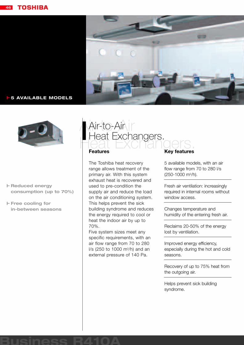
46
Business R410A
Air-to-AirHeat Exchangers.
Air-to-AirHeat Exchangers.Features
The Toshiba heat recoveryrange allows treatment of theprimary air. With this systemexhaust heat is recovered andused to pre-condition thesupply air and reduce the loadon the air conditioning system.This helps prevent the sickbuilding syndrome and reducesthe energy required to cool orheat the indoor air by up to70%.Five system sizes meet anyspecific requirements, with anair flow range from 70 to 280l/s (250 to 1000 m3/h) and anexternal pressure of 140 Pa.
Key features
5 available models, with an airflow range from 70 to 280 l/s(250-1000 m3/h).
Fresh air ventilation: increasinglyrequired in internal rooms withoutwindow access.
Changes temperature andhumidity of the entering fresh air.
Reclaims 20-50% of the energylost by ventilation.
Improved energy efficiency,especially during the hot and coldseasons.
Recovery of up to 75% heat fromthe outgoing air.
Helps prevent sick buildingsyndrome.
5 AVAILABLE MODELS
Reduced energy consumption (up to 70%)
Free cooling for in-between seasons

47
Outdoor unit
Air Flow (h/l) m3/h - l/s
Temperature exchange efficiency (h/l) %
Sound pressure level (h/l) dB(A)
Heat reclaim mode
Bypass mode
Sound power level dB(A)
Operating range °C
Power Input (h/l) W
Heat reclaim mode
Bypass mode
Enthalpy exchange efficiency (h/l)
Heating %
Cooling %
Max. external static pressure (h/l)
Dimensions (HxWxD) mm
Weight kg
Duct diameter mm
Filtration efficiency grade (EU3) %
Power supply V-ph-Hz
Maximum relative humidity %
VN-250SE
250/170 - 70/48
75/77
27/22
27.5/22.5
-10 - 40°C
114/90
114/90
70/73
63/66
80/37
270 x 599 x882
29
150
82
220/240-1-50
85
VN-350SE
350/280 - 98/78
75/77
30/26
31/27
-10 - 40°C
137/128
132/125
69/71
66/69
65/42
270 x 804 x 882
37
150
82
220/240-1-50
85
VN-500SE
500/370 - 140/104
75/77
32/36
33/27.5
-10 - 40°C
188/166
182/164
67/71
62/67
70/38
270 x 904 x 962
43
200
82
220/240-1-50
85
VN-800SE
800/650 - 224/182
75/77
37.5/34
38/35
-10 - 40°C
329/327
325/316
71/74
65/68
110/70
388 x 884 x 1322
71
250
82
220/240-1-50
85
VN-1SAE
1000/810 - 218/227
75/77
37/33
37.5/33.5
-10 - 40°C
391/359
85/355
71/74
65/68
55/35
388 x 1134 x 1322
83
250
82
220/240-1-50
85
Technical specifications heat pump
External air conduit
Piping flange
Indoor air in-take
Piping flange Exhaust Air conduit Fresh air grille
SA(Fresh air)
RA(Indoor air)
(Indoor air grille)
Fresh air conduit
Suspension rod
AOoutside air
EA(Exhaust Air)
Thermalinsulatingmaterials
Heat recovery Heating
18°C
23°C
0°C
Installation example of a VN unit


49
ControlsControlsPanoramic view.
Local Control System pag. 50
Central Control System pag. 51
Network Control System pag. 52

50
Technology is nothingwithout control.
Technology is nothing without control.An innovative and complete range of integrated controls for applicationin the new Toshiba SMMS/SHRMsystems ensure maximum comfortand excellent performance by
perfectly matching the differentrequirements.The range is composed of threecontrol types: local, central and network controls.
Temperature sensor
Improved operationfeatures.
Improved operationfeatures.• Automatic addressing of indoorunits overcomes the need formanually setting each indoorunit individually.• The remote controller enablesthe user to change parameters,such as air flow adjustment
for high ceilings, from theremote controller, and to checkoperating data.• The actual room temperaturecan be displayed at the remotecontroller.
TCC-Linkcontrols.
TCC-Linkcontrols.These controls known as TCC-Link - provide an effectiveresponse to the user's demands.TCC-Link incorporates a two-wire, non-polarity system with
automatic addressing of theindoor units and provides thecommunication link between theindoor and outdoor units.
Contr

51
Compact design and minimised installation space.
Simplified display using icons.
Automatic network addressing.
TCC-Link connections with non-polarised wiring.
Controls
RBC-AMT21E
RBC-AS21E
RBC-AX22CE
RBC-EXW21E
BMS-IFDD01E
BMS-IFLSV1E
BMS-IFWH3E
BMS-LSV2E
BMS-STCC01E
BMS-TP0640ACE
BMS-TP0640TWE
BMS-TP5120ACE
BMS-TP5120TWE
TCB-AX21E
TCB-AX21U(W)-E
TCB-IFCB-4E
TCB-PCDM2E
TCB-PCIN2E
TCB_PCMO2E
TCB-PCNT20E
TCB-PCNT30TLE
TCB-SC642TLE
TCB-TC21LE
Description
Wired remote controller
Simple wired remote controller
Wireless remote controller kit - ceiling
Weekly timer
Digital I/O Relay Interface
TCS-Net Relay Interface
Energy Monitoring Relay Interface
Intelligent Server
Intelligent Server Software
Touch Screen Controller
Touch Screen Controller
Touch Screen Controller
Touch Screen Controller
Wireless remote controller kit - others
Wireless remote controller kit - cassette
Remote location ON/OFF control box
Power peak-cut control board
Error output control board
External master ON/OFF control board
Network adapter
“1:1 model” connection interface
Central remote controller
Remote sensor
Available Applications
SMMS/SHRM - DI/SDI
SMMS/SHRM - DI/SDI
SMMS/SHRM - DI/SDI
SMMS/SHRM - DI/SDI
SMMS/SHRM
SMMS/SHRM
SMMS/SHRM
SMMS/SHRM
SMMS/SHRM
SMMS/SHRM
SMMS/SHRM
SMMS/SHRM
SMMS/SHRM
SMMS/SHRM - DI/SDI
SMMS/SHRM - DI/SDI
SMMS/SHRM
SMMS/SHRM
SMMS/SHRM
SMMS/SHRM
SMMS/SHRM
SMMS/SHRM - DI/SDI
SMMS/SHRM - DI/SDI
SMMS/SHRM - DI/SDI
New R410A VRF TCC Link Control

52
RBC-AMT21E RBC-AS21E IR Remote Control TCB AX21
Control via indoorremote controller.
Control via indoorremote controller.RBC-AMT21ERemote controller.Remote controller type RBC-AMT21E is designed to control single or multiple(maximum 8) indoor units - up to 500 m away if required.Group control.A maximum of eight indoor unitscan be controlled within the sameparameters by a single remotecontroller.The standard remote controllercontains these functions:– Start/stop– Mode change– Temperature adjustment– Air flow adjustment– Timer– Filter maintenance time– Diagnostics and fault codedisplay- Control by two remotecontrollers is available
RBC-AS21ETwo controlling positions.One indoor unit can be controlledfrom two locations using a standard remote controller and a sub-controller type RBC-AS21E.This simplified controller containsthese functions:– Start/stop– Temperature adjustment– Air flow adjustment– Filter maintenance time– Fault code display
TCB-AX21EFunctions of the remote controller.– Start/stop– Mode adjustment– Temperature adjustment– Fan speed adjustment– Timer function– Filter maintenance time– Fault code display– Connection to a second (sub) controller.
Local control systems.
Local control systems.The wired local controller RBC-AMT21E (or simplified modelRBC-AS21E) can monitor a singleunit or a group of a maximum of eight indoor units. It offers the following functions: start/stop, operating mode change,temperature and fan speedadjustment, timer, auto-diagnostics
and fault code display.To define a timer scheduled for eachday of the week, the weekly timerRBC-EXW21E, can be used with a single local or central controller. Its main functions are: weekly programming with differentdaily start/stop cycles, summer/winterprogramming, repeat, clear, day omit.
To facilitate application flexibility, a range of wireless controls is also available (TCB AX21E, TCB AX22CE, TCB AX21U (W)E) to manage the main control functions.

53
Weekly Timer RBC EX21E Central controller TCB SC642TLE
RBC-EXW21EWeekly timer.A weekly timer type RBC-EXW21E can be used inconjunction with a single remotecontroller or a central remotecontroller. The timer contains 7-day scheduling and day copyfunctions and a clock.Functions of the weekly timer– Weekly scheduling– Different cycle times each day– ON/OFF two times each day– Repeat function– Clear function– Summer/winter scheduling– Day omit function– Memory retention for 72 hoursafter power failure.
Central control systems.
Central control systems.
With the Toshiba central controllerTCB-SC642TLE, up to 64 indoorunits can be monitoredindividually, and be divided into 4 zones (up to 16 indoor units foreach zone).In case of Light Commercialmodels (Digital and Super DigitalInverter) maximum 512 indoorunits are controllable by onecentral remote control (8 units in groups per 64 units).The central Toshiba controllers are compact and user-friendly and can also be combined with local controls and a weeklytimer to guarantee optimised usercomfort under any conditions.
Control without indoorremote controllerThe units can be operated fromthe central remote controller only,without using indoor remotecontrollers.
TCB-SC642TLEEnables the individual control of up to 64 indoor units. This controller contains the samefunctions as the main remotecontroller and can display the operating parametersof unit or groups of units such as:• Integrated set-up function• Zone control• Last-touch priority function• Providing full, restricted or nocontrol to the remote controller.

54
Networkcontrol system.
Network control system.Toshiba offers precise control of the new VRF systems in bothstand-alone applications for autonomous monitoring of the air conditioning system, and integrated into a central control scheme together with Super Digital Inverter and
Digital Inverter split systems.The innovative solutions of Toshiba network guaranteemaximised integration with otherbuilding systems such aselevators, fire protection systems,lighting etc.The range of open-network
controls was been specificallydesigned for BuildingManagement Systems.
Touch ScreenBACnet Gateway
Lon GatewayThe Lon Gateway interfacemanages the New R410A VRF air conditioning system as a Londevice to communicate with thecustomer's Building ManagementSystem and to monitoroperational status.Lon Gateway using SNVT signalsand providing the followingfunctions:Command:– ON/OFF– Mode: cool/heat/fan– Temperature setting– Central/localMonitoring:– ON/OFF– Mode: cool/heat/fan/failure– Temperature setting– Room temperature– Central/local
BACnet GatewayThe BACnet system operates inconjunction with the IntelligentServer and uses object signals providing the following functions:– Object signalsCommand:– ON/OFF– Mode: cool/heat/fan– Temperature setting– Central/local– Fan speedMonitoring:– ON/OFF– Mode: cool/heat/fan/failure– Temperature setting– Room temperature– Central/local– Energy monitoring
Touch screen controllerUsing the touch screen controllerwith the intelligent server providesa clear display and enables easyoperation.Command:– ON/OFFNetwork control:– Cool/heat– Temperature setting– Central/localMonitoring:– ON/OFF– Cool/heat– Room temperature– Central/local– Failure– SchedulerEnergy monitoring using thepower meter interface and alocally-supplied power meter.– Fault code display– Operational datalogging/recording
Lon Gateway
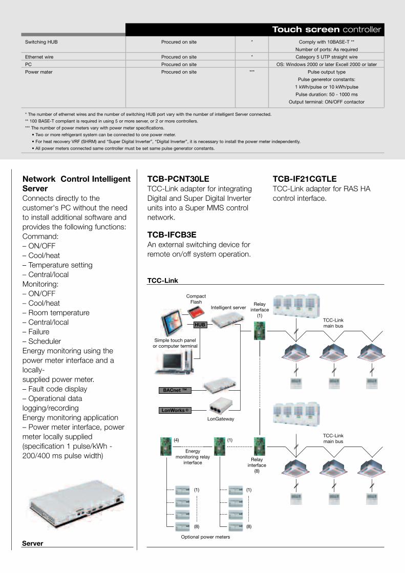
55
TCB-PCNT30LETCC-Link adapter for integratingDigital and Super Digital Inverterunits into a Super MMS controlnetwork.
TCB-IF21CGTLETCC-Link adapter for RAS HAcontrol interface.
TCB-IFCB3EAn external switching device forremote on/off system operation.
Server
TCC-Link
Network Control IntelligentServerConnects directly to thecustomer's PC without the needto install additional software andprovides the following functions:Command:– ON/OFF– Cool/heat– Temperature setting– Central/localMonitoring:– ON/OFF– Cool/heat– Room temperature– Central/local– Failure– SchedulerEnergy monitoring using thepower meter interface and alocally-supplied power meter.– Fault code display– Operational datalogging/recordingEnergy monitoring application– Power meter interface, powermeter locally supplied(specification 1 pulse/kWh -200/400 ms pulse width)
Intelligent server
CompactFlash
LonGateway
Relayinterface
(1)
Relayinterface
(8)
(1)
(1) (1)
(8) (8)
(4)
Energymonitoring relay
interface
Optional power meters
TCC-Linkmain bus
TCC-Linkmain bus
LonWorks ®
BACnet ™
HUB
Procured on site
Procured on site
Procured on site
Procured on site
Switching HUB
Ethernet wire
PC
Power mater
* The number of ethernet wires and the number of switching HUB port vary with the number of intelligent Server connected.
** 100 BASE-T compliant is required in using 5 or more server, or 2 or more controllers.
*** The number of power meters vary with power meter specifications.
• Two or more refrigerant system can be connected to one power meter.
• For heat recovery VRF (SHRM) and “Super Digital Inverter”, “Digital Inverter”, it is necessary to install the power meter independently.
• All power meters connected same controller must be set same pulse generator constants.
*
*
***
Comply with 10BASE-T **
Number of ports: As required
Category 5 UTP straight wire
OS: Windows 2000 or later Excell 2000 or later
Pulse output type
Pulse generetor constants:
1 kWh/pulse or 10 kWh/pulse
Pulse duration: 50 - 1000 ms
Output terminal: ON/OFF contactor
Touch screen controller
Simple touch panelor computer terminal

57
CompComplementary ProductsPanoramic view.
Selection software pag. 58
Diagnostic software pag. 59

58
Selection Software: everything at the click of a button
With ToshibaEverything is easier.
With ToshibaEverything is easier.Toshiba's commitment to thedevelopment of technologicallyinnovative products with improved
performances is complemented by the responsibility to supply moresophisticated
and functional tools for the design,installation and control of thesesystems.
Selection Software: everything at the click of a button.Sophisticated new system designsoftware has been developed for theR410A* VRF and is a useful andirreplaceable support tool forengineers, architects, installers and ingeneral for anyone who wants toapply the innovative Toshibasolutions.
This new Selection Software can beconsidered the most friendly andeasy-to-use selection tool in the VRFmarket.With this software, the user can puttogether a complete VRF system bysimply clicking on the icons for the
indoor units and the other connectioncomponents.It is also possible to define in advancerelevant parameters such as outsideand inside temperatures, fan speed,pipe system length.
The software automatically managesall the parameters entered, and theactual system capacity for theconditions required can be quicklycalculated and simulated during thedesign stage.Using this innovative and highperformance selection software,developed exclusively by Toshiba, the
design of VRF systems is supportedfor the project at the givenconditions. The software constantlymonitors possible design errors andwarns the user, when it exceeds thesystem limits.
* SHRM Selection Software under development.
Graphical representation of the required pipe connection system and pipe sizing.
Specific details and data of the unit selected: heating capacity, sensible and total cooling
capacity, actual cooling capacity, additional refrigerant charge and pricing indications.
Multiple system management as a single project.
Export function to transfer the project report using standard Microsoft ® Word ®
and HTML software.
Automatic regeneration when adding or amending an existing projects selection.
Indoor unit fan speed indication (high/medium/low) on the system report.
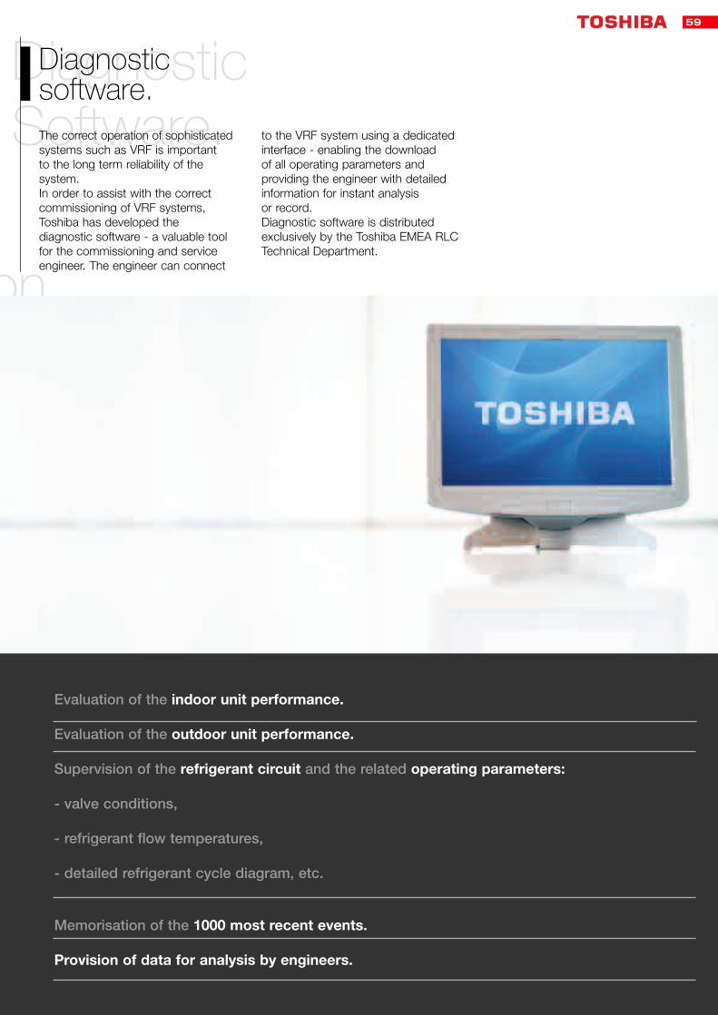
59
tton
DiagnosticSoftware.
Diagnostic software.The correct operation of sophisticatedsystems such as VRF is important to the long term reliability of thesystem.In order to assist with the correctcommissioning of VRF systems,Toshiba has developed thediagnostic software - a valuable toolfor the commissioning and serviceengineer. The engineer can connect
to the VRF system using a dedicatedinterface - enabling the download of all operating parameters andproviding the engineer with detailedinformation for instant analysis or record.Diagnostic software is distributedexclusively by the Toshiba EMEA RLCTechnical Department.
Evaluation of the indoor unit performance.
Evaluation of the outdoor unit performance.
Supervision of the refrigerant circuit and the related operating parameters:
- valve conditions,
- refrigerant flow temperatures,
- detailed refrigerant cycle diagram, etc.
Memorisation of the 1000 most recent events.
Provision of data for analysis by engineers.

60

61
AcceAccessoriesVRF R410A

62
New R410A VRF AccessoriesDescription
Branch Kits
Code
RBM-BY53ERBM-BY103ERBM-BY203ERBM-BY303E
RBM-BY53FERBM-BY103FE
Power cooling
< 6.4HP< 6.4-14.2HP< 14.2-25.2HP25.2HP
< 6.4HP< 6.4-14.2HP
Description
Headers
4 way - 3 pipe8 way - 3 pipe
Code
RBM-HY1043E 4-wayRBM-HY2043E 4-wayRBM-HY1083E 8-wayRBM-HY2083E 8-way
RBM-HY1043FERBM-HY1083FE
Power cooling
< 14.2< 14.2-25.2HP< 14.2< 14.2-25.2HP
< 14.2< 14.2
Description
T-Connector - 2 pipe range
Code
RBM-BT13E
Power cooling
SMMS (2 piping)
RBM-BY53E
RBM-BY103E
RBM-BY203E
RBM-BY303E
RBM-HY1043E
RBM-HY2043E
RBM-HY1083E
RBM-HY2083E
Controls
Y-SHAPE BRANCHING JOINT
4-BRANCHING HEADER
8-BRANCHING HEADER
T-SHAPE BRANCHING
SHRM (3piping)
RBM-BY53FE
RBM-BY103FE
RBM-BY203FE
RBM-BY303FE
RBM-HY1043FE
RBM-HY2043FE
RBM-HY1083FE
RBM-HY2083FE
RBM-BT13FE
Total indoor unit capacity
less than 18kW
18 to 40kW
40 to 70.5 kW
70,5kW or more
Less than 40kW
40 to 70,5kW
Less than 40kW
40 to 70,5kW
For outdoor units connections
Appearance
Branching line up
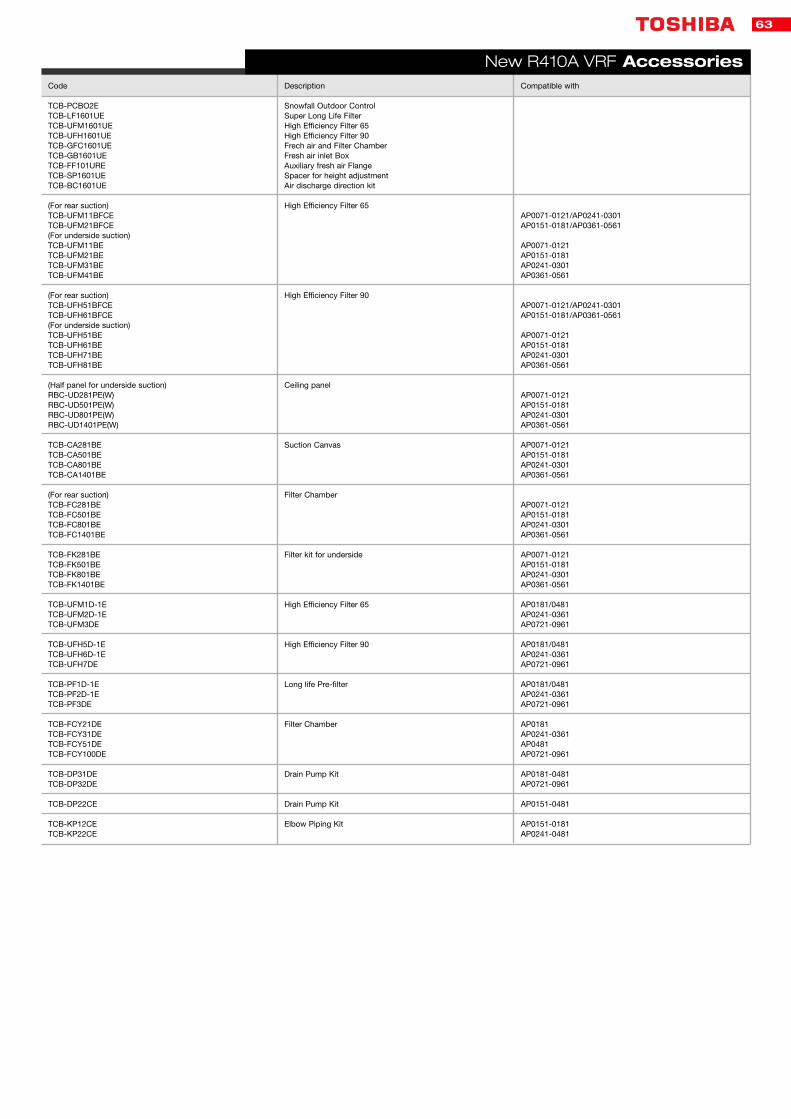
63
New R410A VRF AccessoriesDescription
Snowfall Outdoor ControlSuper Long Life FilterHigh Efficiency Filter 65High Efficiency Filter 90Frech air and Filter ChamberFresh air inlet BoxAuxiliary fresh air FlangeSpacer for height adjustmentAir discharge direction kit
High Efficiency Filter 65
High Efficiency Filter 90
Ceiling panel
Suction Canvas
Filter Chamber
Filter kit for underside
High Efficiency Filter 65
High Efficiency Filter 90
Long life Pre-filter
Filter Chamber
Drain Pump Kit
Drain Pump Kit
Elbow Piping Kit
Code
TCB-PCBO2ETCB-LF1601UETCB-UFM1601UETCB-UFH1601UETCB-GFC1601UETCB-GB1601UETCB-FF101URETCB-SP1601UETCB-BC1601UE
(For rear suction)TCB-UFM11BFCETCB-UFM21BFCE(For underside suction)TCB-UFM11BETCB-UFM21BETCB-UFM31BETCB-UFM41BE
(For rear suction)TCB-UFH51BFCETCB-UFH61BFCE(For underside suction)TCB-UFH51BETCB-UFH61BETCB-UFH71BETCB-UFH81BE
(Half panel for underside suction) RBC-UD281PE(W)RBC-UD501PE(W)RBC-UD801PE(W)RBC-UD1401PE(W)
TCB-CA281BETCB-CA501BETCB-CA801BETCB-CA1401BE
(For rear suction)TCB-FC281BETCB-FC501BETCB-FC801BETCB-FC1401BE
TCB-FK281BETCB-FK501BETCB-FK801BETCB-FK1401BE
TCB-UFM1D-1ETCB-UFM2D-1ETCB-UFM3DE
TCB-UFH5D-1ETCB-UFH6D-1ETCB-UFH7DE
TCB-PF1D-1ETCB-PF2D-1ETCB-PF3DE
TCB-FCY21DETCB-FCY31DETCB-FCY51DETCB-FCY100DE
TCB-DP31DETCB-DP32DE
TCB-DP22CE
TCB-KP12CETCB-KP22CE
Compatible with
AP0071-0121/AP0241-0301AP0151-0181/AP0361-0561
AP0071-0121AP0151-0181AP0241-0301AP0361-0561
AP0071-0121/AP0241-0301AP0151-0181/AP0361-0561
AP0071-0121AP0151-0181AP0241-0301AP0361-0561
AP0071-0121AP0151-0181AP0241-0301AP0361-0561
AP0071-0121AP0151-0181AP0241-0301AP0361-0561
AP0071-0121AP0151-0181AP0241-0301AP0361-0561
AP0071-0121AP0151-0181AP0241-0301AP0361-0561
AP0181/0481AP0241-0361AP0721-0961
AP0181/0481AP0241-0361AP0721-0961
AP0181/0481AP0241-0361AP0721-0961
AP0181AP0241-0361AP0481AP0721-0961
AP0181-0481AP0721-0961
AP0151-0481
AP0151-0181AP0241-0481

Address, CityPhone, Fax
MailSite
Master R
elease 1.0 - February 2005 The manufacturer reserves the right to change the product specifications and im
ages without notice.


