
VT2 t- 130 2A9
IRONLESS ARMATURE TORQUE MOTOR
(Contract No.: NAS-5-11481)
R. L. FisherBrushless D.C. Motors
Sperry Marine Systems Division
Sperry Rand Corporation
Charlottesville, Virginia ZZ901
September 10, 1972
Final Report for Period July 1971 - July 197Z
Report No. JA 7 00-00Z0
Prepared for
GODDARD SPACE FLIGHT CENTER
Greenbelt, Maryland 20771
(NASA-CR-130224) IRONLESS ARMATURE TORQUE
MOTOR Final Report, Jul. 1971 - Jul.
1972 (Sperry Rand Corp., Charlottesville,
Va.) 59 p HC $5.00 CSCL 09C
N73-22416
UnclasG3/15 0206 8
https://ntrs.nasa.gov/search.jsp?R=19730013689 2018-08-20T15:13:10+00:00Z

1. Report No. 2. Government Accession No. 3. Recipient's Catalog No.JA 700-00204. Title and Subtitle 5. Report Date
IRONLESS ARMATURE TORQUE MOTOR September 10, 19726. Performing Organization Code
7. Author(s) 8. Performing Organization Report No.R.L. Fisher
9. Performing Organization Name and Address 10. Wori Unit No.Brushless DC MotorsSperry Marine Systems Division 11. Cetract or Grant No.
Sperry Rand Corporation NAS 5-11481Charlottesville, Virginia 22901 13. Type of Report and Period Covered
12. Sponsoring Agency Name and Address Final ReportP.A. Studer, Code 721 for periodGoddard Space Flight Center July 1971 - July 1972Greenbelt, Maryland 20771 14. Sponsoring Agency Code
15. Supplementary Notes
16. AbstractThis report provides a record of the work performed on NASA contract
NAS 5-11481. The contract involved the development and manufacture of alow-speed ironless armature torque motor (less electronics). Four iron-less armature torque motors, four Hall device position sensor assemblies,and two test fixtures were fabricated.
The design approach utilized samarium cobalt permanent magnets, alarge airgap, and a three-phase winding in a stationary ironless armature.Hall devices were employed to sense rotor position.
An ironless armature torque motor having an outer diameter of 4. 25inches was developed to produce a torque constant of 65 ounce-inches perampere with a resistance of 20.5 ohms. The total weight, includingstructural elements, was 1.58 pounds.
Test results indicated that all specifications were met except for gen-erated voltage waveform. It is recommended that investigations be madeconcerning the generated voltage waveform to determine if it may beimproved.
17. Key Words (Selected by Author(s)) 18. Distribution Statement
Development of a Low-SpeedIronless Armature Torque Motor
19. Security Classif. (of this report) 20. Security Classif. (of this page) 21. No. of Pages 22. Price*
Unclassified Unclassified 58 S .5D
*For sale by the Clearinghouse for Federal Scientific and Technical Information, Springfield, Virginia 22151.
£

pRECENDG G BLyAN
PREFACE
This report provides a record of the work performed on NASA contract
NAS 5-11481. The contract involved the development and manufacture of a low-
speed ironless armature torque motor (less electronics). Four ironless arma-ture torque motors, four Hall device position sensor assemblies, and two testfixtures were fabricated.
The design approach utilized samarium cobalt permanent magnets, alarge airgap, and a three-phase winding in a stationary ironless armature. Halldevices were employed to sense rotor position.
An ironless armature torque motor having an outer diameter of 4. 25inches was developed to produce a torque constant of 65 ounce-inches per am-pere with a resistance of 20. 5 ohms. The total weight, including structuralelements, was 1. 58 pounds.
Test results indicated that all specifications were met except for gen-erated voltage waveform. It is recommended that investigations be made con-cerning the generated voltage waveform to determine if it may be improved.
iii

TABLE OF CONTENTS
Title
INTRODUCTION ..........................
Page
1-1
OPERATING CHARACTERISTICS ..............
TECHNICAL APPROACHGeneral De s c riptionMagnetic Design . . .Armature Design . . .Position Sensors . . .
FABRICATION ...........................
3-13-13-13-93-12
4-1
TESTING ............................... 5-1Introduction .......................... 5-1First Unit - Engineering Model (EM) ......... 5-1Serial Number One (SN 1) ................. 5-5Serial Numbers Two Through Four ........... 5-8Flux Distribution Evaluation ............... 5-20
RECOMMENDATIONS AND CONCLUSIONS ........
NEW TECHNOLOGY .......................
INDEX ................................
6-1
7-1
8-1
iv
Se ction
I
II
III
IV
V
VI
VII
VIII
. . .
. . .
. . .
. . .
. . .
esoeeeeeoloeoe*
oeeeeleeeeoeeee
eoeeeeooeeooeeo
oeeoeo..e...o..
eeee.o...e.o..e
. .. . . . .. . .
. . .. . ..
. . . ... . .
. ... .. *

LIST OF ILLUSTRATIONS
Figure Title Page
2-1 Ironless Armature Torque Motor, Outline Drawing .... 2-3
3-1 Generated Voltage Waveform, Each of 3 Coils,Displaced 120°E .......................... 3-2
3-2 Sensor Output Waveform, Each of 3 Coils,Displaced 120°E .......................... 3-2
3-3 Magnet Assembly .......................... 3-43-4 Magnet Operating Curve ...................... 3-73-5 Winding and Field Position Diagram .............. 3-11
5-1 Ironless Armature Winding Assembly(Resistance vs Time) ....................... 5-2
5-2 EM Generated Voltage Waveform,Speed = 12.45 radians/second. VoltageConstant = 0.474 volts/radian/second peak ........ 5-3
5-3 EM Generated Voltage Waveform of Two PhasesAdded, Voltage Constant = 0.50 volts/radian/second peak ................. ......... 5-3
5-4 EM Hall Device Waveform, Peak-to-PeakVoltage = 1.35 volts ....................... 5-4
5-5 SN 1 Hall Device Waveforms, Input Current: 10 maScale: 50 mv/cm ......................... 5-6
5-6 SN 1 Generated Voltage Waveform, Phase 1 andPhase 2 and Phase 3; Scale: 5 v/cm and 5 ms/cm . . . 5-7
5-7 SN 1 Hall Device Output, Scale: 50 mv/cm and50 ms/cm ............................. 5-7
5-8 SN 2 Generated Voltage Waveform Across Delta,Scale: 5 v/cm and 20 ms/cm . . . . . . . . . . . . . .... 5-10
5-9 SN 2 Generated Voltage Waveform for 01,Scale: 5 v/cm and 50 ms/cm ................. 5-10
5-10 SN 2 Hall Device Waveforms, Input Current: 10 maScale: 50 mv/cm ......................... 5-11
5-11 SN 3 Generated Voltage Waveform Across Delta,Scale: 5 v/cm and 10 ms/cm ................. 5-14
5-12 SN 3 Generated Voltage Waveform for 01,Scale: 5 v/cm and 20 ms/cm ................. 5-14
5-13 SN 3 Hall Device Waveforms, Input Current: 10 maScale: 50 mv/cm ......................... 5-15
5-14 SN 4 Generated Voltage Waveform Across Delta,Scale: 5 v/cm and 10 ms/cm ................. 5-18
5-15 SN 4 Generated Voltage Waveform for 03,Scale: 5 v/cm and 10 ms/cm ................. 5-18
5-16 SN 4 Hall Device Waveforms, Input Current: 10 maScale: 50 mv/cm ......................... 5-19
v

LIST OF ILLUSTRATIONS (Cont)
Figure Title Page
5-17 Flux Distribution Curve For Magnet Widthof 22. 86 mm (0.9 in. ) ................ .. 5-21
5-18 Flux Distribution Curve For Magnet Widthof 10.16 nun (0.4 in. ) ..................... 5-22
5-19 Flux Distribution as Magnet Spacing is VariedFor Single Magnet Configuration ............... 5-23
5-Z0 Flux Distribution as Airgap is Varied For SingleMagnet Configuration ...................... 5-24
5-21 Flux Distribution in Axial Direction For SingleMagnet Configuration . . . . . . . . . . . . . . . . . .. 5-25
5-22 Flux Distribution Curve Using Two Magnets andTwo Iron Pole Pieces ...................... 5-26
5-23 Flux Distribution as Airgap is Varied For DoubleMagnet Configuration ................... 5-27
5-24 Flux Distribution as Magnet Spacing is Varied ForDouble Magnet Configuration . . . . . . . . . . . . . . . . 5-28
5-25 Flux Distribution With Magnets on One Side ofAirgap ................ . . ............. 5- 29
5-26 Flux Distribution in Avial Direction For DoubleMagnet Configuration ...................... 5- 30
vi

LIST OF TABLES
Title
Performance Characteristics .................Ironless Armature Torquer Specifications .........
Properties of Samarium Cobalt Permanent Magnet . . .Calculation for Motor Constant and Weight ........Hall Device Electrical Specifications
(Siemens SV 110-II) .......................
Page
2-12-2
3-33-5
3-13
Test Data Ironless Armature Torque Motor GSFSpecification No. S-721-P-4, Sperry PartNo. 700-00245 SN 2 ................... . 5-8
Test Data Ironless Armature Torque Motor GSFSpecification No. S-721-P-4, Sperry PartNo. 700-00245 SN 3 ........................ 5-12
Test Data Ironless Armature Torque Motor GSFSpecification No. S-721-P-4, Sperry PartNo. 700-00245 SN 4 ....................... 5-16
vii
Table
2-12-2
3-13-23-3
5-1
5-2
5-3

SECTION I
INTRODUCTION
The following report describes the results of the work performed oncontract NAS 5-11481 for the development and manufacture of a low-speed iron-less armature torque motor (less electronics).
This contract involved the design and fabrication of a permanent mag-net field assembly, a wound, shell-type armature for three-phase operationwith the above permanent magnet assembly, Hall effect devices to provide angu-lar position signals proportional to the magnetic field, and structural elementsto integrate the magnet field assemblies into a testable device. Four ironlessarmature torque motors, four Hall device position sensor assemblies, and twotest fixtures were fabricated.
Because of the unique design of this torque motor, there are no break-
away, cogging, or magnetic friction torques. The electrical time constant isvery low. Static decentering forces are eliminated. Heat can be readily con-ducted away from the stationary winding assembly.
Due to the elimination of friction torque, this motor lends itself toapplications in precision position servos and momentum wheels. The electricaltime constant is approximately one-tenth of the time constant of the conventionaltorque motor thus making possible high speed operation. The elimination ofdecentering forces offers a tremendous advantage when mounting motors onelectromagnetic bearings.
1-1

SECTION II
OPERATING CHARACTERISTICS
The specifications for the development of an ironless armature torquemotor per specification No. S-721-P-4 are listed in Table 2-1 and comparedwith tested values obtained from the first engineering model. All specifications
were met or exceeded except for generated voltage waveform and weight.
TABLE 2-1. PERFORMANCE CHARACTERISITCS
PARAMETER DESIGN REQUIREMENTS TEST VALUE(First Engineering Model)
Torque Sensitivity 40 oz-in. /amp minimum 65 oz-in. /amp
Armature Resistance 20 ohms maximum 16. 3 ohms(Delta)
Weight (Wire, 1. 0 lb maximum 1. 07 lbMagnetic Parts)
Outside Diameter 4. 25" maximum 4. 25" maximum(OD)
Inside Diameter 2. 25" minimum 2. 25" minimum(ID)
Sensor Output 4 mv/ma±100 my at 120°E +650 my at 120°E
The design was modified to provide for Hall effect devices external to
the armature assembly and for increased mechanical gaps between the arma-ture assembly and the rotor assembly. The position of the Hall device assem-
bly was made adjustable for optimizing the commutation angle. Hall devices
were mounted so as to provide a sinusoidal output. The zero crossover point
was to be used to provide commutation information. The final performancespecifications are shown in Table 2-2. The outline dimensions are shown in
Figure 2-1.
2-1

TABLE 2-2. IRONLESS ARMATURE TORQUERSPECIFICATIONS
2-2
MOTOR SPECIFICATIONS: VALUES
Torque constant (3-phase delta) 65 oz-in. /amp
Back emf constant (peak) 0. 5 volts/rad/sec
DC resistance per phase 30.8 ohms
DC Resistance (delta) 20. 5 ohms
Inductance (delta) 4.1 x 10 - 3 Henrys
Electrical time constant (L/R) 0.2 x 10 - 3 sec
Weight (including structure elements) 1. 58 lb
Motor friction torque 0
Motor constant (oz-in. /amp/ /ohm 14. 4
Number of poles 12+0. 000in.
Outside diameter 4. 249 0. 00in.-0. 002 in.
Inside diameter 2. 6250 +0. 000 in.-0. 0002 in.
HALL DEVICE SENSOR ASSEMBLY:
Type Hall device Siemens SV 110-II
Input current (green leads) 10 milliamperes
Cycles per revolutation 6
Number of Hall devices 3 Hall devices120 elec degreesapart

-9£
_-I
o
e3
4,izC 00
144
01
a o
.I
4
VJ 0II
a Q
H'.
'I
0 &
z 4~~Q
6 .<
~~
~F
T
a 0
m
I(x
l4)
.-4
P4
/9-
N!
02-3
L I
0oa. DcoNO
/
oO 0r0
Z-a J
40
10
S 0
00ul
010 6
og-e
N
N
40

SECTION III
TECHNICAL APPROACH
GENERAL DESCRIPTION
The ironless armature torque motor is similar in construction to aprinted circuit motor. However, the permanent magnet field rotates insteadof the printed circuit armature. The stator assembly contains the windingsand is attached to an aluminum mounting ring on one end. The stator is posi-tioned in a radial gap. The winding assembly, having no magnetic materials,effects the elimination of magnetic losses.
MAGNETIC DESIGN
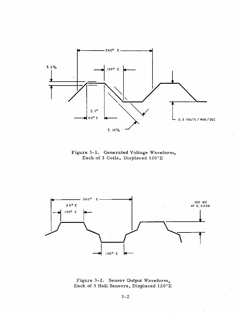
The magnetic design for an ironless armature torque motor requiresa design that is capable of driving as much magnetic flux as possible across alarge airgap. In addition, a very accurately shaped magnetic field is neces-sary to obtain the desired generated voltage and sensor output waveforms (seeFigure 3-1 and Figure 3-2). A square wave magnetic field having a width of120 electrical degrees is desired. For meeting these requirements, a magnetmaterial having a very high coercive force and capable of high flux density wasrequired. Therefore, samarium cobalt permanent magnets, which have thehighest available energy product, were used. The properties of samariumcobalt are shown in Table 3-1. Samarium cobalt has the added advantages ofbeing both an extremely stable material, with practically no long-term varia-tion, and a highly oriented material, which minimizes leakage fields.
The next magnetic consideration was to determine the number of poles.A high number of poles requires tighter tolerances on magnet position, magnetpole span, coil position, and on the position of the Hall device sensors. How-ever, with fewer poles, the back iron for closing the magnetic circuits isthicker. This increases the weight and shortens the possible magnet length.The mean length of turn for the conductors is thereby increased, thus increasingthe resistance.
Four rectangular samarium cobalt permanent magnets, with the dimen-
sions 22.9 mm x 10.2 mm x 6.4 mm (0. 9 in. x 0.4 in. x 0. 25 in. ), were pur-chased from the Raytheon Company. The direction of magnetism was along the6.4 mm dimension. Also, two sample cylindrical samarium cobalt magnets,with the dimensions 12. 7 mm (0. 5 in. ) diameter by 5 mm (0. 2 in. ) length, wereobtained from the Electron Energy Corporation.
3-1
3600 E
1200
+ 30
600 E
10o%
Figure 3-1. Generated Voltage Waveform,Each of 3 Coils, Displaced 120°E
3600 E
0.3 VOLTS/ RAD/SEC
Figure 3-2. Sensor Output Waveform,Each of 3 Hall Sensors, Displaced 120°E
3-2
t3%
100 MVAT 0. 025A
\7

TABLE 3-1. PROPERTIES OF SAMARIUM COBALTPERMANENT MAGNET
MAGNETIC PROPERTIES
Residual Induction, B , Gauss 8,200
Coercive Force, H , Oe 7,800
Intrinsic Coercive Force, Hci, Oe >20, 000
Maximum Energy Product, (BdHd)m, GOe 15 x 106
Intrinsic Energy Product, (41T M x H) , GOe 80 x 106
Reversible Temperature Coefficient, %/ °C 0. 023
Average Recoil Permeability (slope ofdemagnetizing curve) for B/H 0. 2 1. 1
Curie Temperature, °C 750
PHYSICAL PROPERTIES
Density, g/cc 8.3
Open Porosity, % 0
Tensile Strength, psi 8, 000
Flexural Strength, psi 12, 000
Hardness, Rockwell C 55
Thermal Expansion Coefficient, in. /in. /°C 10 x 10- 6
Thermal Conductivity, cgs 0. 02
Electrical Resistivity, ohm-cm 5 x 10⁻⁴
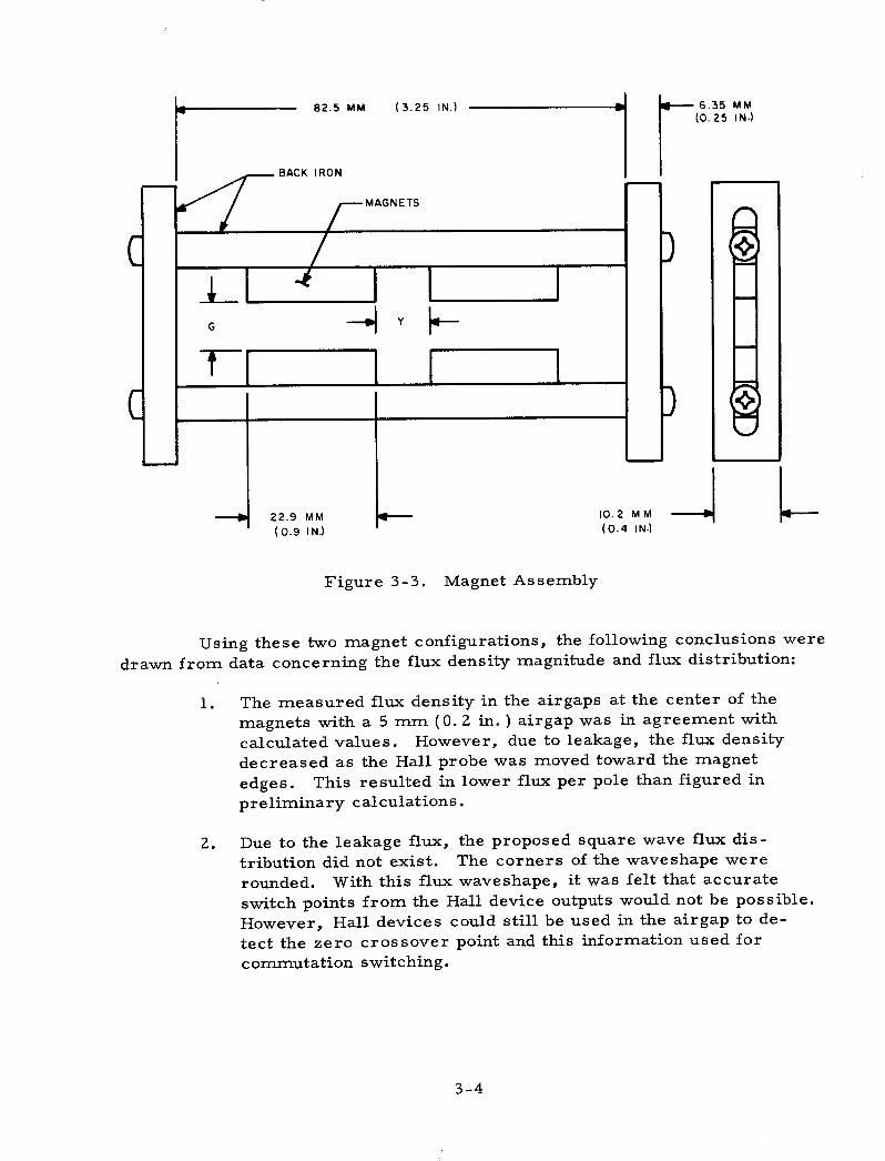
The rectangular magnets were assembled as shown in Figure 3-3. Theflux density in the airgap was measured with a Hall probe and gaussmeter. Theback iron for the magnet assembly was constructed so that both the airgap (G)and the magnet spacing (Y) could be varied. The airgap flux density was plottedfirst with magnets on one side of the airgap and then with magnets on both.
3-3
X
82.5 MM (3.25 IN.) -6 (025 IN)
BACK IRON
' MAGNETS
G
22.9 MM 10.2 M
(0.9 IN.) (0.4 IN-)
Figure 3-3. Magnet Assembly
Using these two magnet configurations, the following conclusions weredrawn from data concerning the flux density magnitude and flux distribution:
1. The measured flux density in the airgaps at the center of themagnets with a 5 mm (0. 2 in. ) airgap was in agreement withcalculated values. However, due to leakage, the flux densitydecreased as the Hall probe was moved toward the magnetedges. This resulted in lower flux per pole than figured inpreliminary calculations.
2. Due to the leakage flux, the proposed square wave flux dis-tribution did not exist. The corners of the waveshape wererounded. With this flux waveshape, it was felt that accurateswitch points from the Hall device outputs would not be possible.However, Hall devices could still be used in the airgap to de-tect the zero crossover point and this information used forcommutation switching.
3-4

3. Evaluation of the magnet spacing indicated that the best generatedvoltage waveform occurred when the distance between the magnetswas equal to one-half the magnet width (120-degree pole span) asoriginally proposed.
4. The motor constant (oz-in. /amp/J-R ) versus airgap was calculatedfor the two configurations. An airgap of 5.85 mm (0.230 in.) gave themaximum motor constant for the configuration having magnets onboth sides of the airgap. An airgap of 5 mm (0. 200 in. ) wasfound to be optimum for the magnet configuration having magnetson only one side.
5. Using various numbers of poles, calculations were made to deter-mine the motor constant and weight for the two configurations (seeTable 3-2). The single magnet configuration was found to haveless weight for a given motor constant for fourteen or more poles.
6. The single magnet configuration was choosen for this design. Notonly is this configuration cheaper to manufacture, but also magnetcost is reduced due to the smaller number of magnets required.
TABLE 3-2. CALCULATIONS FOR MOTORCONSTANT AND WEIGHT
Single Magnet ConfigurationsNo. of Poles Motor Constant Weight (lb)
(oz- in. / amp/l-) Iron Wire Magnets Total
14 9.17 0. 29 0.30 0.31 0.90
16 9.52 0. 25 0. 28 0.31 0.84
20 10. 22 0. 21 0. Z4 0.31 0.76
22 10.49 0.19 0.23 0.31 0.73
Double Magnet ConfigurationsNo. of Poles Motor Constant Weight (lb)
(o oz-in. / amp/ -R) Iron Wire Magnets Total
14 9.27 0.24 0.20 0.48 0.92
16 9.69 0. 21 0.19 0.48 0.88
20 10.35 0. 17 0.16 0.48 0.81
22 10.60 0.16 0.15 0.48 0.79
3-5

In selecting the number of poles for the motor, the objective was toobtain the best generated waveform possible and meet the required weight ofone pound. The weight specification was interpreted to mean the weight of theiron, magnets, and wire only. On this basis, twelve poles, with a calculatedweight of 1. 05 pounds, were chosen.
Motor Design
Using the required motor dimensions and the airgap dimensions ob-tained from the previous studies, the final design was calculated.
OD = Outside diameter = 4. 25 in. max.ID = Inside diameter = Z. 25 in. max.M W = Axial length of magnet assembly = 0. 60 in.
g = Airgap = 0.200 in.Outerring ID = 4. 060 in.
The operating point of the magnets (Bm/Hm) was calculated first.
Bm = g m
Hm Hm Ig
(0.406 in. Z2 ) (0. 250 in.)(0. 387 in. ) (0. 200 in. )
= 1.31
where
Bm = Flux density of magnet
Hm = Field density of magnet
AgAg = Airgap area = 0.406 in. 2 (261.9 mm2
)
Am = Magnet area = 0.387 in. 2 (249.7 mm 2 )
1 = Airgap length = 0. 200 in. (5. 08 mm)
l m = Magnet length = 0. 250 in. (6. 35 mm)
From the magnet curve the induction at a Bm/Hm of 1. 31 is 4. 5 kilo-
gauss or 29 kilolines per square inch (see Figure 3-4).
3-6

BM/HM
_NTRINSI _ \ 7 6 (,,DEMAGNETIZATIONCURVE
MAGNET OPERATINGPOINT m
12 11 10 9 8 7 6 5 4 3 2 I O
DEMAGNETIZING FORCE KILO OERSTEDS
= 1.26
where
0 = Flux in magnet = BA = 11, 200 linesm mm
The= Flux per pole in airgap = 8, 900lines
The number of conductors per phase was obtained using the following
equation:
KTm = 21.4x100 8 xZ xgxP
Z =T1 x A22.4x 10-8 x 0 g 8 P
= 1672
3-73 -7

= Torque constant = 40 oz-in. /amp min
= Number of conductors per phase
= Flux per pole in airgap = 8,900 lines
= Number of poles = 12
= Number of parallel paths = 1
From thisdetermined
calculation, the number of turns per coil (N 1) was
N1z
(C) (2 conductors/coil)
1672(12)(2)
= 69.67
where
Z
C
= Number of conductors per phase = 1672
= Number of coils per phase = 12
To allow some safety factor, use 78 turns per coil (N 2 ). Calculatingthe new torque constant (KT
2), then
KT2
= KT 1 N )
1
= (40 oz-in. /amp) (69.67t
44.8 oz-in. /amp
The actual measured torque constant of the motors was 65 ounce-inch/ampere rather than 44. 8. The actual torque constant was higher forseveral reasons:
1. Since the edges of the magnets were not curved to conform to thecurvature of the airgap, the average airgap was less than 0. 200inch.
3-8
where
KT1
z
P
A

2. Some of the leakage flux still passed through the winding and con-tributed to the torque.
3. Magnets used in the motors appeared to have more output than thesample magnets.
In(LMC) was
order to determine resistance (R), the mean lengthdetermined as follows:
of the conductor
LMC (Dia) iTP
3. 860 TT12
+ (Dia) 1TP(3)
3. 86 oT12(3)
= 2. 037 in.
= 0. 170 ft
where
P = number of poles
W = axial width of coil =
= 12.
0. 64 in.
Consider number 29 AWG wire. R/ft for number 29 wire = 0. 0812ohm/ ft.
R/phase = (LMC) Z (R/ft)
= (0. 170 ft)(1872 conductors)(0. 0812 ohm/ft)
= 25.8 ohms
R(delta) = 2/3 (R/phase)
= 2/3 (25.8 ohms)
= 17.2 ohms
The actual measured resistance per phase for a motor wound with thiswinding was 24.4 ohms or 16.3 ohms for the delta.
ARMATURE DESIGN
The armature design consisted of a delta-wound winding and a mech-support for the winding. The desired generated voltage waveform wasin Figure 3-1.
3-9
+ W
+ 0.64
anicalshown

Assuming that square wave flux distribution as shown in Figure 3-5can be obtained from the magnetic design, the armature can be wound with fullpitched coils having the conductors evenly distributed over the periphery of thearmature shell. Each phase is evenly distributed over 1/3 of a pole span.Therefore, the rotor can move 1/3 of a pole span (60 electrical degrees) withan equal number of conductors in the flux field. This would give a constantgenerated voltage for 60 electrical degrees. Figure 3-5 shows the air gap fluxwaveform and the relative position of the armature coils for three rotor posi-tions (through 180°E).
The generated voltage is given by E = 60 x 108 volts. As-60
suming a constant speed and the flux distribution shown, the generated voltagein each phase will be proportional to the number of conductors in the magneticfield at that position. The table below was developed to determine the conduc-tors and the polarity of the generated voltage in the conductors for the differentrotor positions. The numeral 1 in the table means that all of the conductors forthat side of the phase are in the field. A negative number means reversedpolarity.
Position 1Position 2Position 3
A B C Al B 1 C0 1 1 1 0 1 11 1 0 1 1 01 0 -1 1 0 -1
The generated voltage E
leg of the delta is in parallel with
= Eb = E + Ethec athe other two legs.
(Figure 3-5) since one
Position 1 E1
= E= 1 + 1 = Z1Z B
= E + Ec
= 1 +1 + 0 + 0 = 2a
1 - EB = 1 + 1 = 2
B12
Position 3 E 1 2
= E + E =0+0+1+1= 2c a
= Ec + Ea =(-)1 + (-)1+ 1 + 1 = 0c a
Therefore, the generated voltage across phase B from position 1 toposition 2 is constant. The generated voltage decreases linearly from position2 to position 3. As phase B moves toward the center of the next pole, the gen-erated voltage builds up again but of opposite polarity.
3-10
E12
Position 2

K- 1200 E
PM FIELD 0
A B C Al B' C/
POSITION I 1000101O0001 ® ®l® ®l ~9(
A B C IAl B/
C/
POSITION 2 00 o o01o o 00 ol ®®®®11 ®
APOSITION 3
DELTA WINDING
B C A/ B' C/
E
I 3A
Figure 3-5. Winding and Field Position Diagram
3-11
I 0001001l0010O01®l®®1®®
180 ° E

However, the generated voltage waveform obtained was not trapezoidalas desired, but approximately sinusoidal. This waveform will result in highercommutation torque ripple. A sinusoidal rather than trapezoidal waveform wasobtained for the following reasons: 1) Due to leakage flux, the flux distributionin the airgap of the motor was trapezoidal close to the magnets but becamesinusoidal further away from them (toward the outer ring). Consequently, mostof the conductors were cutting a sinusoidal flux rather than the desired squarewave flux. 2) The coils for the winding assembly were wound on a rectangularcoil form. Because of the tension variation when winding on a rectangular coilform, the coil sides were not straight. As layers of wire built up, the coilsides became more contoured. Consequently, a conductor was not seeing a con-stant flux across the axial length of the motor, but was integrating the flux oversome area based on the curvature of the conductor. This condition could havebeen improved by extending the coil end turns well past the rotor axial lengthand by performing additional coil forming after the coils were wound. Thiswould require additional space for end turns and increase the armature resistance.
POSITION SENSORS
F. W. Bell thin film Hall-Pak generators had been tentatively selectedfor use as angular position sensors. However, after studying the flux distri-bution waveforms obtained from testing the sample magnets, it appeared thatthe Hall device waveform was going to be more sinusoidal than trapezoidal.Therefore, consideration was given to using the zero crossover point on thesensor waveform for switching. In order to have as steep a slope as possibleto use for switching, a high sensitivity Hall device was desirable. Therefore,the Siemens SV 110-II was choosen. Its characteristics are listed in Table 3-3.
When the first motor was built, it was found that the Hall devices werelocated close enough to the magnets so that the output waveform was trapezoidalas desired (see Figure 3-1). However, it was decided that larger mech-anical gaps were more desirable. Therefore, the Hall devices were moved outof the motor airgap so that the ID of the winding assembly could be increased.The Hall devices were then located 0. 045 inch from the side of the magnets andwere used to detect the side-leakage flux. The output voltage was approximatelysinusoidal and the output varied from Hall device to Hall device, from 45 mvaverage-to-peak to 150 my average-to-peak with 10 ma control current.
3-12

a
I
. a oi
_l'-
ttI I
-i ' ' '
1_
_ _
_ _
_ I
!~
VA
5 1 l x
I I i,
.+
I
I i
, I
I 1
1 7&
I
,-, I
I 1L;
E
"
2 oC,.
-, PS :
~FIP o
_ *
0 C
O
C
2 o
CS
@
E
° °
o
0 0
0 o
E
m
b,.. o
..,
E EE °
co
' E
E
C
>-8
E
a
a- g
E-'m ~~
s%
rr~
-orr
L3
E
>E
>
S
· C: Ci
o,, P
o 2 O
r
6 aolQ
a a
N
A.j
a 0.l
a C
m
mII
VII
a a
0 U
.0
oa
a aI
NJI 0
Vii
Vm
l m
o
CC
, C
C
0 C
0C
-
'- O
'
o -
.a
.o
=
-C
,
oC..
O
.2 $
0L
a
0 a
0 0
-u
0 2
.0
Iai!2n-
1 II
r. 9
U) R:~J
-
EI_oo 11III!j`4
I-40VUdZ
pL1
Hu
¢4V
EE.c.2_E oc.B:
E0Lo_c)
C)
m
c
.,.0
-a oC
-.0
Et-
~E
o
E
E
>
0c 0
-C
.
n og
___o
(U a.
Cfl .
cn 00
n*
~-.2>
CC
OC
~
3-1
3
I\ <
~ :-i-N
~~~ < X
.oD
S4
oi a
-I
851a-
Zm

SECTION IV
FABRICATION
The rotor assembly consisted of a magnet assembly, an outer magneticring, and aluminum structural elements to connect the two members. The air-gap between the outer ring and the magnet assembly was 0. 508 centimeters(0. 200 inch).
The magnet assembly was made up of twelve (12) samarium cobaltpermanent magnets which were cemented onto the OD of an ingot iron ring. Slotswere put on the OD of the ring to position the magnets. In an attempt to squareup the flux distribution in the airgap, the magnets were left rectangular inshape rather than rounding the edges to conform to the curvature of the airgap.
The samarium cobalt magnets were purchased already magnetized.
Necessary care was taken in handling and assembling these magnets due to the
high magnetic pull and brittle nature of the magnets.
After the magnet assembly was placed on the aluminum support, theouter ring was cemented into place. A nonmagnetic shim had to be placed inthe airgap during assembly to prevent the outer ring from being pulled into themagnets.
The winding assembly was constructed by cementing individual coilsonto an epoxy-glass ring, connecting the coils, and potting the assembly. Analuminum mounting ring with terminals was provided on one end. After the
winding assembly was potted, the ID of the assembly was machined.
The coils were wound onto a rectangular coil form. The wire was
coated with a cement as it was wound so that the coil would retain its shapewhen removed from the coil form.
An engineering model was fabricated with the Hall devices in the air-
gap of the motor. Slots were placed in the epoxy-glass ring to locate the Hall
devices. Hall devices were assembled after the potting and final machining ofthe winding assembly. This design provided for the minimum radial clearanceof 0. 006 inch.
The configuration was revised to provide larger mechanical clearances.
Hall devices were mounted into an epoxy ring so that the OD of the ring would
4-1

pilot into the ID of the winding assembly mounting ring. The sensor ring as-sembly was mounted against the test fixture with three screws. The test fix-ture was slotted so that the position of the sensor assembly would be adjustablefor phasing the sensors with the winding for best commutation.
Hall devices were located nominally 0. 045 inch axially from the mag-net assembly and thus sensed the side leakage flux. The OD of the winding as-sembly was reduced from 4. 045 inches to 4. 025 inches by changing the wiresize of the winding from 29 gage to 30 gage. With the Hall devices removedfrom the ID of the winding assembly, the ID was increased to 3. 790 inches.
These changes required making both a new mold for the winding assem-bly and a mold for the sensor ring as well as modifying the test fixture.
The winding assembly was potted with Scotchcast Resin 251, which isa filled epoxy. It is a medium viscosity, rigid, class F (155°C) resin system.The resin was warmed in order to lower its viscosity for maximum impreg-nating ability. Nevertheless, voids still occurred and had to be filled.
The sensor ring was made of the same epoxy so as to be compatible.Each Hall device was cemented into a slot in the sensor ring and then coveredwith a conformal coating for protection. (The Hall devices were found to beextremely fragile. )
4-2

SECTION V
TESTING
INTRODUCTION
Tests were performed to evaluate each unit manufactured and to eval-uate flux distribution with various configurations. The results of the tests arepresented in this section.
FIRST UNIT - ENGINEERING MODEL (EM)
During final machining a wire was nicked causing one phase to be open.Test data on the unit was obtained from the two good phases and is presented inFigures 5-1 through 5-4. Mechanical data is listed below.
Motor Characteristics (Hall Devices in Airgap):
No. of TurnsGage WireResistance (Delta)Voltage Constant
78 turns per coil2916. 3 ohms0.47 volts/radian/second peak
Breakdown of Weight:
Rotor Assembly
Outer RingMagnetsYokeHousingClamp Ring
Total Rotor Assembly
105.7 gm146.4 gm67.2 gm
177. 0 gm1Z. 0 gm
508. 3 gm
Winding Assembly
Terminal RingWireEpoxy
Total Winding Assembly
27.9 gm165. 0 gm14.1 gm
216. 0 gm
5-1

? h. t
;F'
-t-t
tti:; -~it '
:_ _l
...
'i i.t
H ,
-+..--
-...
Ti
1-
Ft
h74
ttt4
NiEU
,. ,7 "Tpt _
U)
o* 4
o,-_
-4 W
>
¢ kc,-v
o P
tn4b
.r, h
5-2
1- L
ti
4,!!-
7 Lh?:.
.i-f'LL
-;II4
7iiIt-L-!N
I:Z
.
T
I4
44-"
I--, r-
LL
-1T
-
-...sL
:
I
7: i~!
.:
| _ L,_
I , 1,
1 X
,- ttt:7i
,--r T ; 'Lii
.-, ~'~
:~- +
,t -~_
I .:i~
i~~
rii rtt
-lb.F~~.
L t~-

Figure 5-2. EM Generated Voltage Waveform,Speed = 12.45 radians/second.Voltage Constant = 0.474 volts/radian/second peak.
Figure 5-3. EM Generated Voltage Waveform ofTwo Phases Added, Voltage Constant = 0. 50volts / radian/second peak.
5-3
/ /'- I I / I I I I I I I I I I I I ' I I I II I I I t I I I I I I I I I f 1 1 1 1 1 1 1
rI I i I \ I I I I t-
--I

Figure 5-4. EM Hall Device Waveform,Peak-to-Peak Voltage = 1.35 volts.
Motor
Rotor AssemblyWinding As sembly
Total Motor
508.3 gm216. 0 gm
724.3 gm or 1.6 lb
Wire and Magnetic Parts
Outer RingMagnetsYokeWire
Total Wire & MagneticParts
105.7146.467.2
165. 0
484. 3
gmgmgmgm
gm or 1.07 lb
The winding temperature rise was measured by suspending the windingassembly in the air and measuring the voltage and current at time intervals(see Figure 5-1). A current of 0. 700 ampere was applied to one phase. Theultimate temperature rise per watt was 4. 5 watts per degree centigrade. Thethermal time constant was 7. 5 minutes.
5-4

SERIAL NUMBER 1 (SN 1)
Test data for serial number 1 is presented in Figures 5-5 through 5-7.Mechanical data is listed below:
Serial Number 1 - Ironless Armature Torquer
Motor Characteristics
No. of TurnsGage WireResistance (Delta)Voltage ConstantTorque Constant (Peak)
78 turns per coil3020. 7 ohms0. 50 volts/radian/second peak70.7 ounce-inches/ampere
Breakdown of Weight
Armature (Total After FinalMachining)
CoilsMounting RingEpoxy plus Phonolic Ring
for Coil SupportRotor Assembly
(Less Alum. Housing)MagnetsYokeOuter RingAluminum HousingSens or As s embly
Total Weight Less AluminumHousing
Total Weight IncludingAluminum Housing
Total Weight of Electricaland Magnetic Parts(Wire, Iron, Magnets)
177. 3 gm
ill.28.37.
1 gm3 gm9 gm
324. 6 gm
152. 1 gm67.1 gm
105.4 gm178.1 gm35.8 gm
537.7 gm
715.8 gm
435.7 gm
5-5

, ,, ,~ ,,,, , , , ~ I
'~ ,i Z- } -r /
Figure 5-5. SN 1 Hall Device Waveforms,Input Current: 10 maScale: 50 mv/cm
5-6
I1 f I I ,~I I~ I I III I~ If I# I 11
'~~ II I~~'1

Im
rf 'X~~~~~~~~ _.
I II I I I ' l II I I II I I II I
Figure 5-6. SN 1 Generated Voltage Waveform,Phase 1 and Phase 2 and Phase 3Scale: 5 v/cm and 5 ms/cm
Figure 5-7. SN 1 Hall Device Output,Scale: 50 mv/cm and 50 ms/cm
5-7
___~~i ___ I I I I II 1A~ ' A ad 11IAL 15L........ i 111'L
D7"XZ)TL1'1/1 ' "! ' I'l'l'l""'' V v k :V V V
_1I -

SERIAL NUMBERS 2 THROUGH 4
Serial numbers Z through 4 were manufactured just as serial number 1.Serial number 2 had a nicked wire which appeared to be just insulation scrapedoff and which did not effect performance. A drawing change was necessary toinsure that this did not happen again.
The test data for serial number 2 (SN 2) is presented in Table 5-1 andFigures 5-8 through 5-10; test data for serial number 3 (SN 3) is presented inTable 5-2 and Figures 5-11 through 5-13, and test data for serial number 4
(SN 4) is presented in Table 5-3 and Figures 5-14 through 5-16.
TABLE 5-1. TEST DATA IRONLESS ARMATURE TORQUEMOTOR GSF SPECIFICATION NO. S-721-P-4
SPERRY PART NO. 700-00245 SN 2
1. Insulation Resistance @ 100 VDC
p1 to Case > /50(0 Megohms
P2 to Case 2 fS/i (2 Megohms
p3 to Case >i/5l) Megohms
2. Resistance @ 25°C
P1 3/b 4 ohms
P2 3 67 Ohms
P3 3j I Ohms
3. Inductance (Disassemblied - Winding Only)
,01 3, 04 c Millihenrys
P2 3 -4 * Millihenrys
,3 03 C4 Millihenrys
4. Inductance (Assemblied)
P1 4- bY ) Millihenrys
02 4 6 1/ Millihenrys
03 4 61/ Millihenrys
Delta 4.i4 Millihenrys
5-8
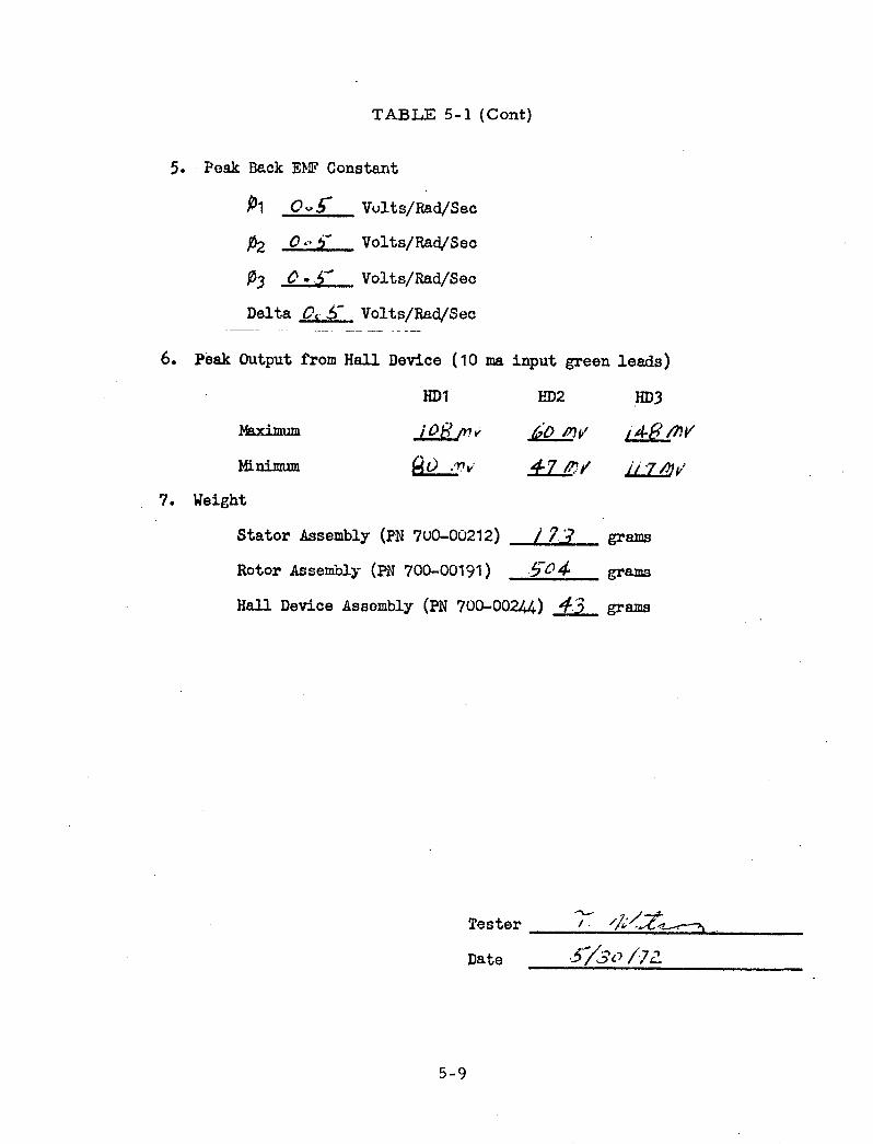
TABLE 5-1 (Cont)
5. Peak Back EMF Constant
P1 OVS5 Vults/Rad/Sec
P2 O Volts/Rad/Sec
P3 O Volts/Rad/Sec
Delta C £- Volts/Rad/Sec
6. Peak Output from Hall Device (10 ma
HD1
mnximum .
Minimum _
input green
HD2
-7 ~/
7. Weight
Stator Assembly (PN 7u0-00212) / 73
Rotor Assembly (PN 700-00191) .5- 4
Hall Device Assembly (PN 700-00244) ,3
Tester -
Date
grams
grams
grams
3o /7f
5-9
leads)
HD3
i/7 ,l'

i I '\I f 1\ A IJ/ I I I I \ I I Il I Il J I! I I! I I I I I 11I
Ij-
Figure 5-8. SN 2 Generated Voltage Waveform Across Delta,Scale: 5 v/cm and 20 ms/cm
Figure 5-9. SN 2 Generated Voltage Waveform for 01,Scale: 5 v/cm and 50 ms/cm
5-10
4% ^ - : Ift - - j AA1 11 I 11 II: 11 11 ^
..0 M M.1 I. II 1.I IEus Ie I III II.I I i

1,/,!~ ~ill '
./~/~.~~.~/,A ,.-,jI,~A.A,~,
:- v l' lw
I l ti I/I IV r/ I _
,Iq/III Vll Io t C /
u T U
Figure 5-10. SN 2 Hall Device Waveforms,Input Current: 10 ma - Scale: 50 mv/cm
5-11

TABLE 5-2. TEST DATA IRONLESS ARMATURE TORQUEMOTOR GSF SPECIFICATION NO. S-721-P-4
SPERRY PART NO. 700-00245 SN 3
1. Insulation Resistance @ 100 VDC
A to Case >/10ooo0 Megohms
P2 to Case 2/oo,/oo Megohms
P3 to Case > Z/X 0 Megohms
2. Resistance @ 250C
P91 3 aO. Ohms
P2 3A.8 ' Ohms
)03 30'
o° ohms
3. Inductance (Disassemblied - Winding Only)
01 c30S&{ Fdllihenrys
p2 *. 0 3 11illihenrys
3 -3. 03, Mi llihenrys
4. Inductance (Assemblied)
i1 -. Millihenrys
P2 4. 5o0 Millihenrys
03 2,.3 3 Millihenrys
Delta 33, 3 ? Millihenrys
5. Peak Back EMF Constant
P1 0o 5 Volts/Rad/Sec
,P2 °O - Volts/Rad/Sec
P3 °O Volts/Rad/Sec
Delta 9. • Volts/Rad/Sec
Leads to windingterminals reversed.Correct phasing fordelta is as follows:
A 3-6B 2-4C 1-5
03C
NOTE: The rotor assem-bly for this motor containsthe outer ring that had theoverhang reduced to .015inches.
5-12

TABLE 5-2 (Cont)
6. Peak Output from Hall Device (10
HD1
Maximum .?3,-"M
Mini mum IO e/pv
7. Weight
ma input green
HD2
81 y f6r'j
Stator Assembly (PN 7u0-00212)
Rotor Assembly (PN 700-00191) -
Hall Device Assembly (PN 700-00244)
leads)
HD3
110 M le,-1n tV
grams
grams
grams
Tester //
Date _ C //z
5-13

'--/ I/ -IIfle ''I,,J,, .~' ~ 1 / III1~ ~~:,, ,,,, ..,, ,I, ,,, ,1,,
I \~~~~
I U :
Figure 5-11. SN 3 Generated Voltage Waveform Across Delta,Scale: 5 v/cm and 10 ms/cm
Figure 5-12. SN 3 Generated Voltage Waveform for 01,Scale: 5 v/cm and 20 ms/cm
5-14
I~1 I A:- A A I1IITI IT$ 1 It l T IT III 1,,~ I,, I,,I IfT , ,IT,,, 1, I,
I A I 1-1 t I IT!r~/ / L~A

X f A I A A AA
I
v
~l Vl , U ~~ _T _ 1o ~
111,,,1,I/~,1111 1
Figure 5-13. SN 3 Hall Device Waveforms,Input Current: 10 ma - Scale: 50 mv/cm
5-15

TABLE 5-3. TEST DATA IRONLESS ARMATURE TORQUEMOTOR GSF SPECIFICATION NO. S-721-P-4
SPERRY PART NO. 700-00245 SN 4
1. Insulation Resistance @ 100 VDC
P1 to Case ,o. -op Megohms
P2 to Case 2 7,oo ,o Megohms
p3 to Case Q 2,ojo0 Megohms
2. Resistance @ 250C
p1 3 /, 5 Ohms
P2 3 /s ohms
P3 3/ 3 Ohms
3. Inductance (Disassemblied - Winding Only)
P1 '3. 0 2 Y Millihenrys
P2 3. o/' Millihenrys
03 3. 0 2- Millihenrys
4. Inductance (Assemblied)
p1 Millihenrys
P2 ' Y/ 1 Millihenrys
p3 4' 9 Millihenrys
Delta Y,/A Millihenrys
5. Peak Back EMF Constant
1Pi -t-- Volts/Rad/Sec
~P2 '4 d_ Volts/Rad/Sec
P3 '^ Volts/Rad/Sec
Delta -47 - Volts/Rad/Sec
. t
iC ', : i ,
5-16
4L
-3
HD 1
HD 2
HD 3
6
Low
03 (3-5
02 (4-2
03 (1-6
High
- 1-6)
- 3-5)
- 4-2)

TABLE 5-3 (Cont)
6. Peak Output from Hall Device (10 ma
HD1
Maximum Oft i_ V
Minimum 4'Le 1
input green
HD2
!1/-1 v, V5o%
leads)
HD3
5°th /
7. Weight
Stator Assembly (PN 7U0-00212) /8/ 7 grams
Rotor Assembly (PN 700-00191) 502 grams
Hall Device Assembly (PN 700-00244) 4 3 grams
Tester , 7 4-
Date 7 X 6k 7 '7 Z. __
5-17

L~~~~~~~~~~~~~~~~~~~~~~~~~~~~~~~~~~~~~.1-- Ialj I,,,,,,,1,.1,I,,X,,
Figure 5-14. SN 4 Generated Voltage Waveform Across Delta,Scale: 5 v/cm and 10 ms/cm
Figure 5-15. SN 4 Generated Voltage Waveform for 03,Scale: 5 v/cm and 10 ms/cm
5-18

I ._i I A. i 1 .. _ i. , I n _
,]. Il11[ 1I Jll .11~ ll fi fi ~ 'k! Xf, 111t 1 ~ ilXAf
'1 1E I'1~ l'Ul
i ! ' 1111 f -l ILI ''l'lI IT 1' l [ 11 1' '
U lU Ii 11 wII J 1V I I V liP
L I~ ,III II,,L I Jll'ly'17'1ll'[11'1l'l T'll'/'l 'l'l'I[ ~'[ 'll 'IX'l' '[ ]
Figure 5-16. SN 4 Hall Device Waveforms,Input Current: 10 ma - Scale: 50 mv/cm
5-19

FLUX DISTRIBUTION EVALUATION
The sample magnets were mounted into various configurations to studythe flux distribution. The data obtained is presented in Figures 5-17 through5-26.
5-20

C. ++HI
Ei
H .E
..
.....
..... .......
illlll~~
llllll-ll~IIIIlIIIllllll
_,, i-Hi HH
.__ J , g .
...
i....
S~~~~kk ~~~~4
i i -H
+ 11
1.!..t.
1!1
111!1
11111111111lllllllllllllllll
HS g g
i j
1, tX
{f-01f10!f~~~~~~~~~~~~~~gl~~tif10:|11 f lfi4!
l'si1 11N
l~~~~~~~~~---------
S~
~~
~~
~--
---------ljli
iliS
1S
19jN
j1
]llll l1
;11
~]11j; ~
lM1j
S~~~~~~~~~~~~~~~~~~~~~~~~~~~~~ --tli i
----1 !l 1 1 1 --
-----|| --iilliiilllLlIL
tI~liill2
W i
W W
i
l:11
11
ililt1
||1
|}lll:lill~l]!~
lgl~
llillI lil~
lli +
X S S X
W
W SIIIIIIIa~il 1110
1 IllllitX-I-llllllllli jliIIItl' Illl~l444J
4mllm
i
AX
lllllllli
!tlllll]jl|; l 111X1111Illll~llt4TM-l~
W~~~~~~~~~~~~~~~~~~~~~-
4 IllI~
I
ll~illll4
I1IlIlIiill
tllliii~i
+ 1
SilllllF
ill(I~Il{
l ~ 1
11ll1
!tll l:t|X
~~~~~~~~~~~~~~ -------IIlll
-iil --li
-- --- 4f~IIlI~I1111W
WW
WX
~
lb
liilliill~ill~
iliillil lIlll~I~
~lIIlT
Fm
:iM
g g
M lS
l! litllli!1
i1
$ 1
l 211i Ii~
llill!lHiH
oIoNco ,-4
04-)o-4P.,r.04kU)
.4)k(9Li~[3
.itH
H:
44.
4 --4Il
L IT
I
-4
-H44
..
T.
..
TT
UT
T
}T
T
TU
T
TT
T1n
T
n T
ri
T
[TT
m
P4', I F j j tt irs Hti d1+t
Ti 111 i H
tWF +1M
I Ll 11 TlI I rr,
, llrtT
T
' I
' i;
N
r rlIrrr:T
H
I
I I
E
I n
T
I i
[ I
I IIllT
r.+lr
IIIIIIFli
ffii 1111111111111
rFiL
D-l
,LE
LL
r 1w
l S
nrrE
l l'll
IIIIIi1T
IIIIT
r T
{ T
H
LLLT
:1
i
i i i
L n 1 } t Fm f il rIl,1
LLU
M
IL.
r T
T1r
TT
rz
rT I r
T
n T
T
TM
T
H11E
lFLT
r +
I }
rTrH
<
1
I L LLlLIfI I I I I I I I 191 IllLI
r, , § n * 1 i
i 1 §
LT
I I
I L r
1 1 i 1 1 1 1 1 i !
XT
X
TT
X
:T
l9t l4
itItT
tt M
T
llIptI9
L]
lr
ETTtilnl T
fflT
TtT
3T
#t
TT T | t m
Tt
t t t 1 1
t 1 { TX I I
1111111!11 i X
X
11
X
X
THlillT9llfrT
rTT
TT
T
IITT
T
T
m
El T
i I
I n T T
T
TT
T 1 T
TT
F I
ITT
rr X
I r
rlrn44rm
H
T
eT
T
nilltp
il IlililL
IIIIII
n:em f
m m
m m
lI!lltilfi!!inT
TT
I
T
n r
L ,
I, .
,,, .
., s
, '
' '
l ,,,,
, .,,,,,
E
rn rimn T
ffl TLLH TneI 1ll e
IIlilillTlilr
n+
Trrrn
T
n
T7L
I T
TI
I T
ET
I
I 11
I I
I T
I
I I
T
1 T
I
I I
I
rmlm
n In
llllli nlllllllllll
I ! z I, I I s
] ]
T
n T
r L
lfIr n t
TT
r o 1ln
n
n 1 x
1 n +
1 r r r r
I IT C
l I
Ll
llilililil g X
X W
t m g ILL LSi1t
! I
I 1
i I
] T
rn
TT
TT
T
T
T
I |
I I
I i
I I
I T
ET
T
n
l cr
N
A
r
l! ttl+
lul
Tm
n
T1H
I
I I
I IIm
i3
30
111S
I !
.i
I !
i I,
Tg
TS
X
h
$g
X
lklllk
llS
E
X
X
X
Tlllll rl X
g -zllllm
lllll
5-21
:= 7 T
T
Tn
, 1 ll g] ¢z
] sZ
:y ]ff
.....
i j
..
......... iIiij
iiii X
r'i 1
11 1 11
IlIlilll~] l
lIIIIIIIIIIS~iii
l~iilillttl}
iliHl-44-HI+IIIx
~~
~~
~~
~---
-|N
E|E
Z
H1
rv
4r+-HlT~
----------lillllli~
lli~
iN Il!IIII!IIII!I
S Illlll~~~~~~llllllllll~ ~ ~
~ ~
~4lllr +r
llllllllllnllll-lllllll
H~~~~~~~~~~~~~~~~~~
H .......
llllllllllllfllrmplu
~l~
~rrn
ili
!!!!!IIi!!T-
~ ln
~m
l ll~
l~III-l!!lm
llu
M Il:
llllllll lllllllllllll~
lu~
llr~~
~
X ~ ~
~ ~ ~
------
!I!IIIITM
1
-Tlll~
l~l
-- -----
l~lll
m
:m
:I

S-SI
4~
~~
~~
~~
~~
~~
~~
~~
~~
-
0,H-40 40.ool-~4
cb! O'
0to-H
11~
~~
~~
~~
~~
~~
~~
~~
~~
~~
~~
C-
-- ------------
~ ~
~ ~
~ ~
-- ------------
0~~~~~~~-------------
~~
~~
~~
~~
~~
~~
~~
~~
~~
~~
~=
+
------ ~
~
--------- -
-~~
~~
i H
i
4---- ----
4-+
---------
++
-H+
~
4+, ~ ~ ~
~ ~
~ ~
~ ~
~ ~
~ ~
~ ~
~~
c+
...~
~~
~~
~~
~v
---- -------
~
-4:~
~~
~~
~~
~~
~~
~~
~~
~~
~~
~~
~~
~~
~~
~~
~~
:4-
P4~~~i
tH-f±
-~~
~~
~~
~~
~~
~~
~~
~~
~~
~~
~~
~~
~~
~~
~~
a
TE
E~
~~
~~
~~
~~
~~
~~
~~
~~
~~
~~
~~
~~
C
5-22

....
..
t lllllllllll
l l
l l
l ~~~~~~~~~~~~~~~~~~~...
..
...
.~~~~~~~~~~~~--- ---
.---....---111111111---.1
l
ll l
l ll
l l
l- -
E
., ,
! lllllllII:
-111111111111111111S
S1m
W1111111..........1
111111111
: T: ----
: +
II~
lstlt:5
: llllllllllllllllll~
lllllllllll~uiiiiillllllri
_ SlW
|I, ,.,,,
.||Mu .IIII
I 111X1
rrlll 11111 |11 1-T 11
-ri11
1
: i 1111111111211X
:
lillililiililillililiilildi~ililillililiililillililiarlarpT~a~lI I IiiT I
Ir
..
.i1
111111121111
t 1
11
11
11
11
11
11
21
21
11
t@1
11
11
11
11
11
11
1$
11
11
11
11
01
11
11
11
S1
W1
41
IIIII
I T I
I~
+H
414+
++
-IIIIIII
llllllllllllll tttltllllllllllE
l¢
m
~l~
alr
...
...
.. .
111 li--------.----
-------- --------
tm
m
t~lliilitl
lellt~
l
..
..
! llllllllllll m
.
IIIIIIIIIIIIp~
pllll1
111llll~
llllllllIIIII~k~
diT
~m
IIII4-
4
0~
~~
~~
~~
~~
~~
~~
~~
~~
~~
~~
~~
~~
~~
~~
~~
~~
~~
~~
~~
~~
~~
~~
~~
~~
~~
~~
~~
~~
~~
~1
I
.1 3 .
i T
t4 i'-_
.+1
11
11
11
1t
_ll~
l~l~
ll]~lllillm
l~lllllm
llltlll-l~l
ffi -it
X 1llllli1 0ifLLL tit:1 1 ittli
5-2
3
.-4
oQ
0U) *-4
a. o
bo o "
044-)Q
.U)
..4
Ir q

'0.r.
O*
o.
4-.k
k
ID
0 U
k (
5-2
4

e
X4-
-i
0
-4
,8-4 -
.r4
0
-4 u]
r- O
.,a
fT-l
Lf)r
5-2
5
7777---
;Tz47:
Z
z ----~
I
il
.iI1�
I:
:LL
�-I]i.IE-T:iI :!�;� ti
ij
tttf7�14MII
� -Z
E-
E1--
. -tt -
-i _
__.._
_
-
-·
-.pI
T z---
L

tTT
~~
~~
~~
~~
~~
~~
~~
~~
~~
~~
T~
~IT
~~liiillii ijiiii-i
l ii.~
~~
~:~
~__iiiii~
~f~
'~i~
·~~
f~~
i~i'~
~..
..
.... ...
w~
~~
~~
'
----t--
:T?:::~
~~
A.
'I-iT
:7
:,-_:-:
i:::~:.rr~
~~
~
I ~tr
~1:-f_3L~-~;T
i.. -L
.. ..
...
7 = .
.. ..
4 ,-
: :
: :
I :
i..wJ
ef. ...
i' ~ ~
Ti
w :::: : :~ m
i : , w-
· L
,1~
~~
~~
~~
~~
~~
~~
~~
~~
~~
~~
~~
~~
~~
~~
~~
~~
F::: II--.:
w:
T
~ ~
~ ~
~~
I: :
1:!::: :i:
w~
:....~~
~:
-·:·· illlllli
::~~j±--4
i +
1::.:i:::~
~~
~~
~~
~~
~~
~~
~~
~~
~~
~~
~~
~~
~~
~_:~
±T
-:M
l
Ir_:-i:::::lllr l
...~~~~~~~~~~~~~~~~~-ITT ..
...
4: -
4i~
i
A:
T!
w:sl
:::i~
·:~~
~~
~~
~~
~~
~~
~~
7
jjjji~~~i ~
~ -7
....,. L
T:~
~
i::::l ::::i:::i:~
~~
~~
~~
~~
~~
~~
~~
~~
~~
~ i-:
";~~~~~LI
: .:
.I .
._
I-_'j:.:.:
liabilities J-�-' �'_-
-"].....
... �
:::J�:
L
; �.... .
--. --i- H
-- -- -. - -. --jj--�� � I
I I -__ I I I
I tI1�
(d04)
:3 Q
u -
%
0
k4i
0
PirN1I
5-2
6

1Ca)
.,4o.,
.-4A
O 0
§lo
04
0(d
·rH
.e4
O
m
-0
4)
Sq 0
,c tO
._~~~~~~~~~~~~~~~~~~~~~~~~~~~~~~~~~~~~~~~~~~~~~~~~-sH
)q
AD0
k,
h ·rqCF
5-2
7
1 -- T
-
_
-tLL.t
' H
I'--
1j -
-
7ztT+ ?.
$-.
-T.- -i
:::-7_ _: [:

4..
4U.,-
0 4-1
4Ad
Ki
O
bO -40
In
o 4-)
u~
*, k
a,
*4-
o
0h 4a
L
l
U)
sH.O
hr~
5-2
8
_ _1, X
toZ
Z
-L-f~
l--r
4I--
=4-
1
_
-r-
_ !
_ I

,$ 'lI
.wQ)
.9 cdO
k
.11
Py¢0
°4r.
OH
;j e",
h o.
0
4. 4
ul
5-Z
9
LnNIa)k.,h-4
_ _ _l I
£ :
I
-
--
t .
_ l1_ m
_ T
_ _ _
,-i- X
';iY4 In
j-,
' l
t
L-:F
E--:
-i- ~- 1

-44+
~~
~~
~~
~~
~~
ffi:i 11
te llZ
ilJ
i llrl
l 1
11
11
1
I Jli[
l~ld
1 ll[]
lil[[ ill
l~
[ [
[ ~
} l~
lili[I][ ~
[ ~
lE4l[i;ItttI
[ I
[ Il
I T[ l
I ,
I [I
I] 11[l:[[[litl~
Tl~
~~
~~
~~
~~
~ll[]lll~
~~
l~~
fjl~~
lltljj[[II I[[
II
I · ·~~~~~~~~~~~~~~~~~~~~~~
I
; .,
iv ,[] ,lll[T
~llllllltl]lll~
~
gg~
llFF
Fll~
lll[~~lJ]11~ll{~i~llll
i 1[111ii[ll- IiT
[TT
II
,ll ill
I:1il
111 l
; lll# , : : : .Iq
; ~
11III~
lilllllllllli411[ll]]J
i4i
I T
lii,
-1
r~~
~~
~~
~~
~~
~~
~~
~~
~~
~~
~-
S $]
2 i
ett
iil tlillT
llFIe
E
S
E.I]
., ll][
~a{]d
r'Tllillll~
l~llZ
a l~
ll[l4ll~
ll~ll
llllll~ll~
l~lIfIH
I!I
i~~
~~
~~
~~
~~
~~
~~
~~
~~
~~
~~
~~
~~
~~
~~
1H
I
~44 qq4~
T
T~~i
iij[~~
~~
~
,t, m
g
, ,
, *,],lq
l~]1
]T
i
, I
I T
11
T
l T
I
4 i
Tt i
I ~ i l t I 1 1 1
T
i l l ~ i l ] ] l l l l l
i t
l l l l
l l i
l l l l l l
l l
I1
, 1
iW
ttt i
I I 1 l l
J i i l d l lllll ~ i l lT l i i l lll[ll l l l l
I T
4 IITI
TI
I I
F I
z+
I t
L
! L
[]l
l l
l I1
li li
lllll lllL
, I
d
4~~~~~~~~~~~~~~~~~~~~~~~~~~~~~~~. ;T~ I IgWt
II 11
II-T
, Ii
I it
I
~H ]i
i 11
llilillli lllllli;1111ll~
lll!l-l-H-
' '
..
..
..
,I
i:t [~li
ilialltlllh t-t-t
~11 ~ II m
I
III I]T
T[T
IEIIli
Etlb
,
T I
i~~
~~
~~
~i
-ir 1
i ; i
i 1
i
-t-~+
., 4
T
I I
T, ''
IIIIIIIIIIIllll~F
l9!lll~
l!Im
H~
~~
~~
~~
~~
~~
~~
~~
~~
H
I~ :
[ J~[~trr]r
~l i1
[[[[1[
X
m
~I i;", SX
0111 ... i ... lJ:[[]!!!!"....
[i,~:~;rmlll:::l:itllllllllltlll:1
j ,!l[!ili
l l
l l
_ j
X-
+ ...
tl!l! .
.,w
....... ial Lmt -1!! llTlflL lilllkllllnl~~iiIiiiilIlIIiiiiiTZ
..............,
.................. lilrilIlX L nii::::::::!iiiililili t ........... ilil
I III~
Ii :
[ IuI ...................
~i
im
i;:11;llil
.... .
'"'"
'"]
............. ..
"'
I l
ll l
l~l'"
"[''"
l;]1"11l]
.... "........
W1 Ilibll r
TX
ltW
$T
]4II[l
X
mlii4
ttlllliiii iii11111l~
illliii1111~1
:1 l
1itrlH-
I ·........ II
..... +
H
~.;
J :11i~ll 1
1 ;
~ 'llrr
i qtlll~l!
lil jllllf]]
Il r~
lll~rlrrlm
llllllllllllT
:i ,lll~
i+
:"~~~~~~~~~~~~+H
1+,
i, ~
--4
+m
++
-4
!!!.... !!!,,
lifl I
I]LI~
... ! .........
.... IlE
llll
IilEI[]l
...... -H
rH-liH
F
iH
i H
i
L:~
~~
~~
~~
~~
~~
~~
~~
~~
~~
~4
S.,~
~~
_
i; !l!,
,,' ~
'T...
,[/'. '
,., .
i I
,_
._
: ~'
:' iiW~ll~~il!111~
I!111!]1
111!!1
11111111~
IT
I11' II
~llllI
IT
Ii '!
i~ i ii i i '
' ,
1~
~~
~~
~~
~~
~~
~~
~~
1
zif ±
L~
~~
~~
~~
~~
~~
~i
li l
·li]111illillll~
l!11
I
EE
'·I '~
IJ
~
ll i
i ~
4 1
1 1
l i
i 1
l !
~ ~ i li-,l''~
l
l !
~ l
1 !
r
i i i;
AtI +it
;ili,_~--_
*
-
Lt.
._
;- _
+:- ·
_-
::0-.4
O4)
-4
0 0-4
0
4-4
0
bo
Cl
-4
0,,-
0 o
..q
o0
I:
FX,
! !]: :IIi2tttH:
,-_.-
11 I
-r
.2
32m~ .
5-3
0
,
i

SECTION VI
RECOMMENDATIONS AND CONCLUSIONS
The ironless armature torque motor developed on NASA ContractNAS 5-11481 met or exceeded all specifications except for the generated volt-age waveform. It is recommended that further effort be made to investigatethe effect of coil shape on generated voltage waveform and to develop methodsof improving the flux distribution.
The ironless armature torque motor is recommended for use in appli-cations requiring low friction torques, low electrical time constants, or lackof decentering forces. High speed applications should be investigated.
Consideration should be given to making the outer magnetic ring,which is part of the rotor assembly, part of the stationary winding assembly.This would both reduce the overall weight due to the elimination of structuralelements and provide a mechanically stronger stator assembly while addingvery little magnetic friction.
6-1

SECTION VII
NEW TECHNOLOGY
Contractor by letter dated August 14, 1972 reported noinventions were made in the performance of work under thiscontract. Such report was made on DD Form 882 and copiesforwarded to the Contracting Officer, Mr. P. Videniers.There were no discoveries, improvements or innovations madein performance of this contract other than reported in Contractor'sFinal Project Report JA 700-0020 dated September 10, 1972. Thebasic concept of the ironless armature torquer as applied toBrushless DC Motors is new technology. The use of samarium
cobalt permanent magnets in the design of the ironless armaturetorquer is new technology in that this is one of the few motorapplications that can effectively use this magnet material.
7-1

SECTION VIII
INDEX
Armature Design ............................Conclusion . . . . . . . . . . . . . . . . . . . . . . . . . . . . . . .Fabrication ................................First Unit - Engineering Model ...................Flux Distribution Evaluation ....................Introduction . . . . . . . . . . . . . . . . . . . . . . . . . . . . . .List of Figures ..............................List of Tables ............................ . .Magnetic Design .............................Motor Design ..............................New Technology ............................Operating Characteristics ......................Position Sensors ............................Preface . . . . . . . . . . . . . . . . . . . . . . . . . . . . . . . . .Recommendations . . . . . . . . . . . . . . . . . . . . . . . . . .Serial Number 1 . . . . . . . . . . . . . . . . . . . . . . . . . . . .Serial Numbers 2 through 4 .....................Table of Contents ............................
3-96-14-1
...... 5-1...... 5-201-1
...... 3-1...... 3-13-67-12-13-12. .111
6-1...... .....5-5
5-8iv
Testing . . . . . . . . . . . . . . . . . . . . . . . . . . . . . . . . . . . . . .
8-1
Subject Page
5-1


![Series GW control valves - SMS TORK...Valve Travel [%] 10 20 30 40 50 60 70 80 90 100 FL 0.9 0.9 0.9 0.9 0.9 0.9 0.9 0.9 0.9 0.9 Valve Size Orifice Dia. Travel Rated Cv Inch mm Sign](https://cdn.vdocument.in/doc/165x107/5f4fb482064cf52aed0d638f/series-gw-control-valves-sms-tork-valve-travel-10-20-30-40-50-60-70-80.jpg)

