W-CDMA for UMTS – Principles
u Introductionu CDMA Background/ History
u Code Division Multiple Access (CDMA)u Why CDMA ?u CDMA Principles / Spreading Codesu Multi-path Radio Channel and Rake Receiver
u Problems to Solveu Macro Diversity and Soft Handoveru Near-Far Problem and Power Control
u UMTS General Requirementsu FDD vs. TDDu Key Parametersu Spectrum Allocation

UMTS Networks 2Andreas Mitschele-Thiel, Jens Mueckenheim Oct. 2012
References
H. Holma, A. Toskala (Ed.), “WCDMA for UMTS”, 5th edition, Wiley, 2010.A.J. Viterbi, “CDMA, Principles of Spread Spectrum Communication”, Addison-
Wesley, 1995.R.L. Peterson, R.E. Ziemer, D.E. Borth, “Introduction to Spread Spectrum
Communications”, Prentice-Hall, 1995.T. Ojanperä, R. Prasad, “Wideband CDMA for Third Generation Mobile
Communication”, Artech House, 1998.R. Prasad, W. Mohr, W. Konhäuser, “Third Generation Mobile Communications
Systems”, Artech House, March 2000.

UMTS Networks 3Andreas Mitschele-Thiel, Jens Mueckenheim Oct. 2012
CDMA History
Pioneer Era (Spread Spectrum)40s and 50s: Spread Spectrum technique for military anti-jam applications
1949: Claude Shannon and Robert Pierce develop basic ideas of CDMA
1970s: Several developments for military systems (e.g. GPS)
Narrow-band CDMA Era
1993: IS-95 standard (mainly driven by Qualcomm)
1992–1995: RACE project CODIT (UMTS Code Division Testbed, PKI, Ericsson, Telia, etc.)
Wide-band CDMA Era
1995–1999: ACTS project FRAMES: FMA Mode 1 (TD/CDMA), FMA Mode 2 (W-CDMA)
1995: cdma2000 1x/ 3x (USA)
1998: UMTS (Rel.-99): FDD and TDD mode
1999: Harmonization: W-CDMA, TD-CDMA and multi-carrier CDMA (chip rate: 3.84 Mchip/sec)
1999: Narrowband TDD mode (TD-SCDMA), chip rate: 1.28 Mchip/sec
High-Speed CDMA Era
since 2000: HSDPA (Rel.-5/ 2000), E-DCH (Rel.-6/ 2002), HSPA+ (Rel.-7/ 2005)
cdma2000 1x EV-DO/DV
UMTS Networks 4Andreas Mitschele-Thiel, Jens Mueckenheim Oct. 2012
Spread Spectrum Technology
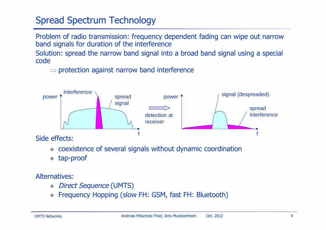
Problem of radio transmission: frequency dependent fading can wipe out narrowband signals for duration of the interferenceSolution: spread the narrow band signal into a broad band signal using a specialcode
Þ protection against narrow band interference
Side effects:u coexistence of several signals without dynamic coordinationu tap-proof
Alternatives:u Direct Sequence (UMTS)u Frequency Hopping (slow FH: GSM, fast FH: Bluetooth)
detection atreceiver
interferencespreadsignal
signal (despreaded)
spreadinterference
f f
power power

UMTS Networks 5Andreas Mitschele-Thiel, Jens Mueckenheim Oct. 2012
Spreading and Frequency Selective Fading
FDMA: Relatively small bandwidth oneach channel
u Guard bands to avoid interferencebetween the users
u Channels maybe (temporary)unavailable due to channelselective fading
CDMA: relatively large bandwidth ofthe spread signal
u Frequency selective fading causesonly some reduction in the level ofthe received signal
u Users are separated by thespreading sequence
22
22
2
frequency
channelquality
1
spreadsignals
frequency
channelquality
1 23
4
5 6
small bandwidth guard band
UMTS Networks 6Andreas Mitschele-Thiel, Jens Mueckenheim Oct. 2012
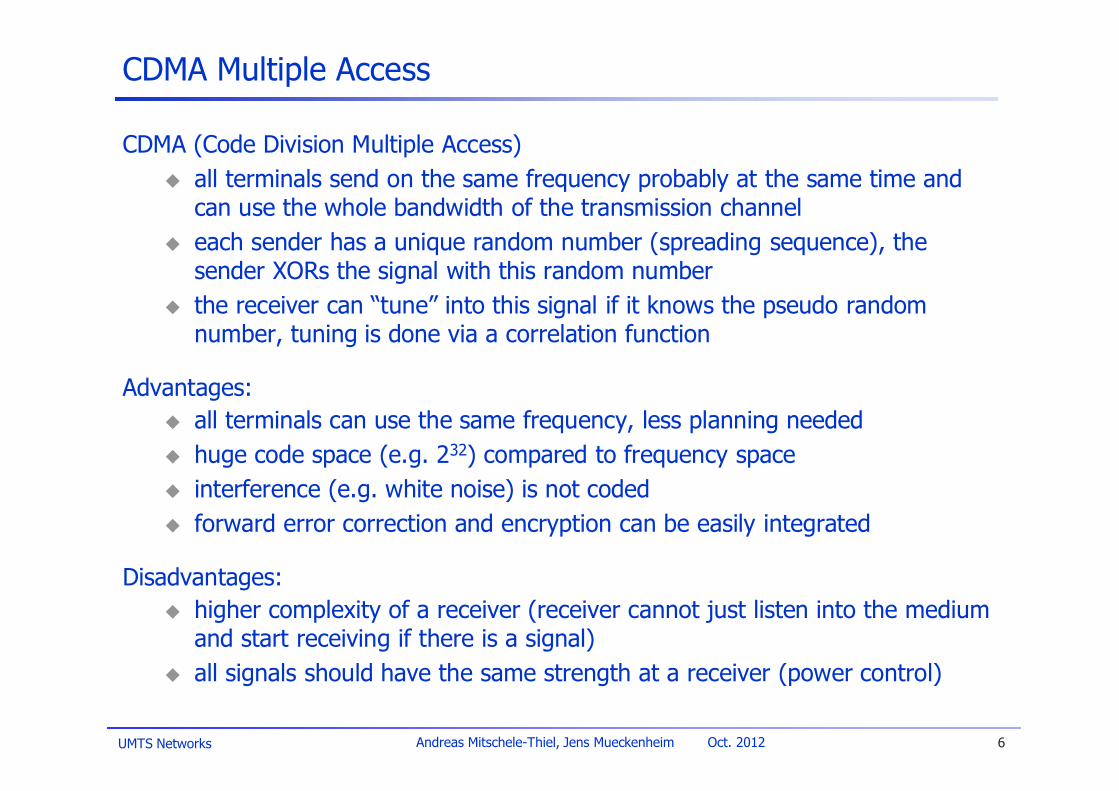
CDMA Multiple Access
CDMA (Code Division Multiple Access)u all terminals send on the same frequency probably at the same time and
can use the whole bandwidth of the transmission channelu each sender has a unique random number (spreading sequence), the
sender XORs the signal with this random numberu the receiver can “tune” into this signal if it knows the pseudo random
number, tuning is done via a correlation function
Advantages:u all terminals can use the same frequency, less planning neededu huge code space (e.g. 232) compared to frequency spaceu interference (e.g. white noise) is not codedu forward error correction and encryption can be easily integrated
Disadvantages:u higher complexity of a receiver (receiver cannot just listen into the medium
and start receiving if there is a signal)u all signals should have the same strength at a receiver (power control)
UMTS Networks 7Andreas Mitschele-Thiel, Jens Mueckenheim Oct. 2012
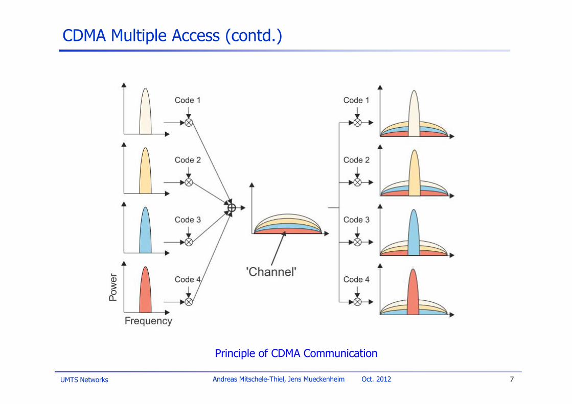
CDMA Multiple Access (contd.)
Principle of CDMA Communication

UMTS Networks 8Andreas Mitschele-Thiel, Jens Mueckenheim Oct. 2012
DSSS (Direct Sequence Spread Spectrum) I
XOR of the signal with pseudo-randomnumber (code sequence)
u Many chips per bit (e.g., 128)result in higher bandwidth of thesignal
Spreading factor SF: ratio betweenchip rate RC and data rate Rb
u RC = Rb · SFu tb = tC · SF
Processing Gainu GS = 10 · log10(SF)
user data
codesequence
resultingsignal
0 1
0 1 1 0 1 0 1 01 0 0 1 11
XOR
0 1 1 0 0 1 0 11 0 1 0 01
=
tb
tc
tb: bit durationtc: chip duration
(data rate)
(chip rate)
(chip rate)

UMTS Networks 9Andreas Mitschele-Thiel, Jens Mueckenheim Oct. 2012
DSSS (Direct Sequence Spread Spectrum) II
Xuser data
codesequence
modulator
radiocarrier
spreadspectrumsignal
transmitsignal
transmitter
demodulator
receivedsignal
radiocarrier
X
codesequence
basebandsignal
receiver
integrator
products
decisiondata
sums
correlator
UMTS Networks 10Andreas Mitschele-Thiel, Jens Mueckenheim Oct. 2012
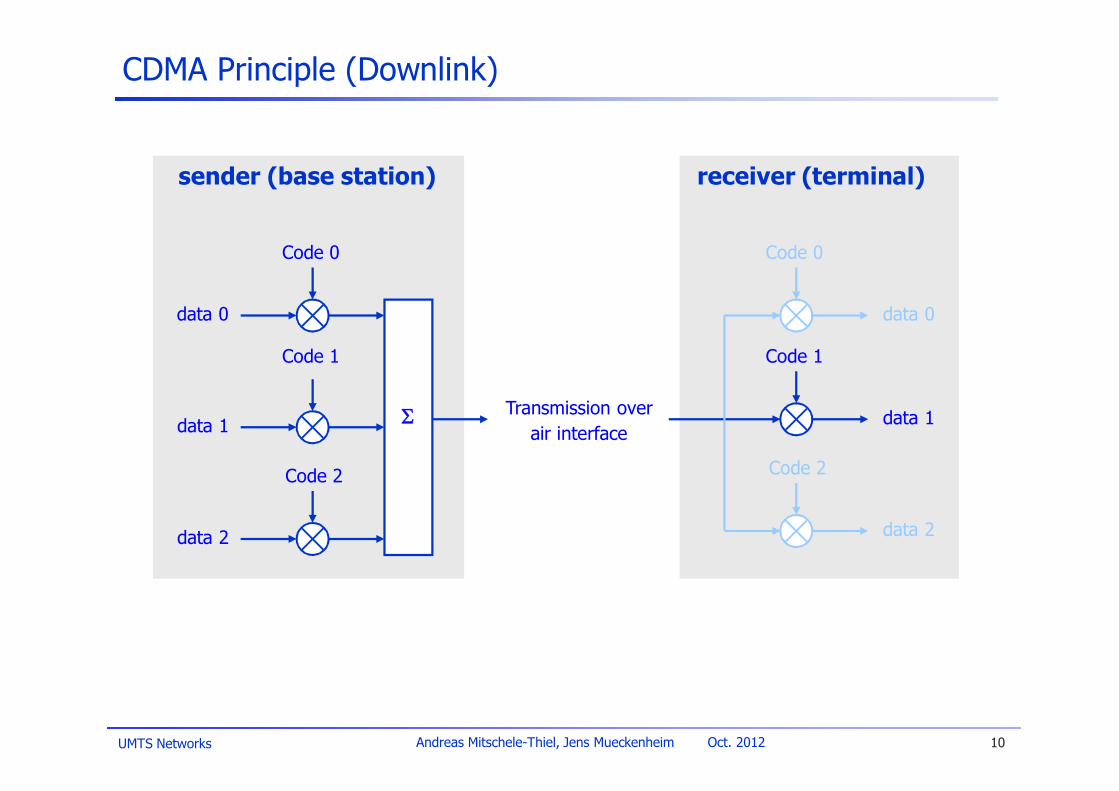
CDMA Principle (Downlink)
Code 0
Code 1
Code 2
S
data 0
data 1
data 2
Code 0
Code 1
Code 2
data 0
data 1
data 2
sender (base station) receiver (terminal)
Transmission overair interface
UMTS Networks 11Andreas Mitschele-Thiel, Jens Mueckenheim Oct. 2012
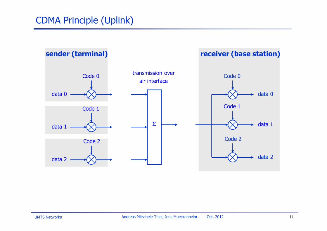
CDMA Principle (Uplink)
Code 0
Code 1
Code 2
S
data 0
data 1
data 2
Code 0
Code 1
Code 2
data 0
data 1
data 2
sender (terminal) receiver (base station)
transmission overair interface

UMTS Networks 12Andreas Mitschele-Thiel, Jens Mueckenheim Oct. 2012
UMTS Spreading
u Constant chip-rate of 3.84 Mchip/s (FDD)u Variable data rates are realized by different spreading factors of the
orthogonal channelization codesu Higher data rates: less chips per bit (and vice-versa)
u Senders are separated by unique, quasi-orthogonal scrambling codesu Simple code management: each station can reuse the same orthogonal
channelization codesu No need for precise synchronization as the scrambling codes remain
quasi-orthogonal
data1 data2 data3
scramblingcode1
chan.code3
chan.code2
chan.code1
data4 data5
chan.code4
chan.code1
sender1 sender2
scramblingcode2

UMTS Networks 13Andreas Mitschele-Thiel, Jens Mueckenheim Oct. 2012
Functionality of Channelization and Scrambling Codes
Channelization Code Scrambling CodeUsage UL: Separation of physical data
(DPDCH) and control channels(DPCCH) from same terminalDL: Separation of DL connectionsto different users within one cell
UL: Separation of terminals
DL: Separation of sectors/cells
Length 4 – 256 chips (1.0 – 66.7 µs) UL+DL: 10ms = 38400 chips
Number of codes Number of codes under 1scrambling code = spreadingfactor (SF)
UL: several millionsDL: 256
Code Family Orthogonal Variable SpreadingFactor
Long 10 ms code: Gold code
Spreading Yes, increases transmissionbandwidth
No, does not affect transmissionbandwidth
UMTS Networks 14Andreas Mitschele-Thiel, Jens Mueckenheim Oct. 2012
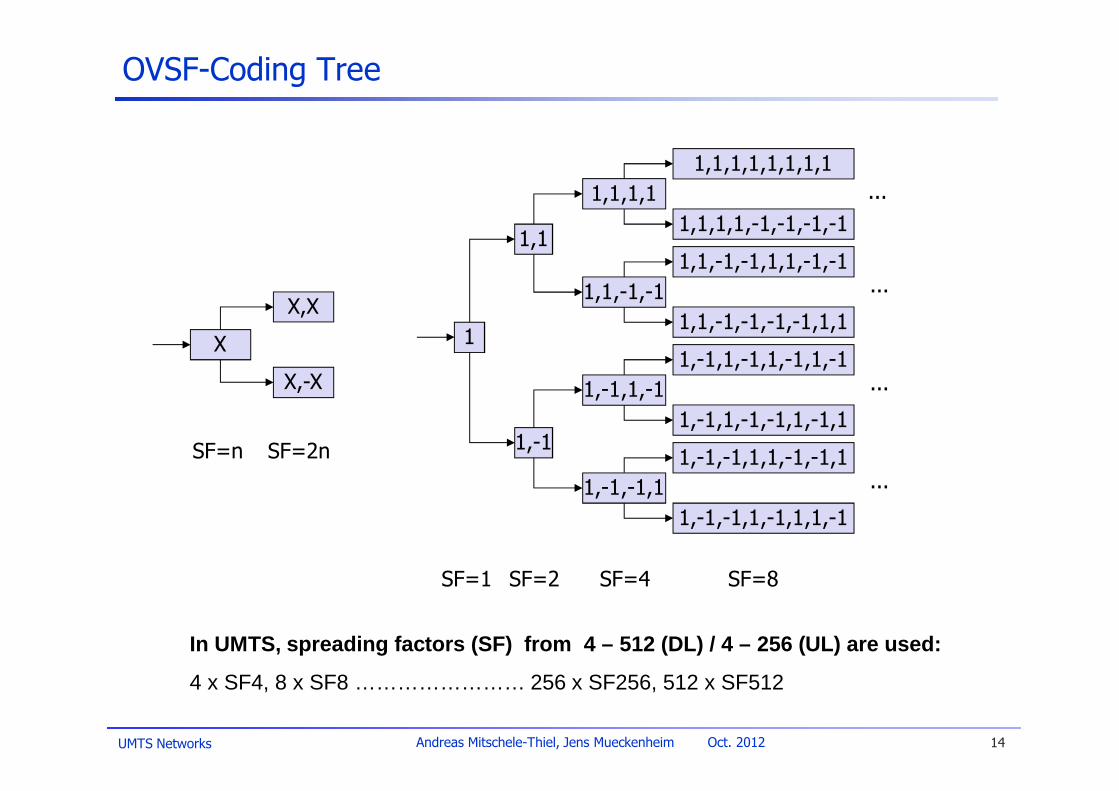
OVSF-Coding Tree
1
1,1
1,-1
1,1,1,1
1,1,-1,-1
X
X,X
X,-X 1,-1,1,-1
1,-1,-1,11,-1,-1,1,1,-1,-1,1
1,-1,-1,1,-1,1,1,-1
1,-1,1,-1,1,-1,1,-1
1,-1,1,-1,-1,1,-1,1
1,1,-1,-1,1,1,-1,-1
1,1,-1,-1,-1,-1,1,1
1,1,1,1,1,1,1,1
1,1,1,1,-1,-1,-1,-1
SF=1 SF=2 SF=4 SF=8
SF=n SF=2n
...
...
...
...
In UMTS, spreading factors (SF) from 4 – 512 (DL) / 4 – 256 (UL) are used:
4 x SF4, 8 x SF8 …………………… 256 x SF256, 512 x SF512
UMTS Networks 15Andreas Mitschele-Thiel, Jens Mueckenheim Oct. 2012
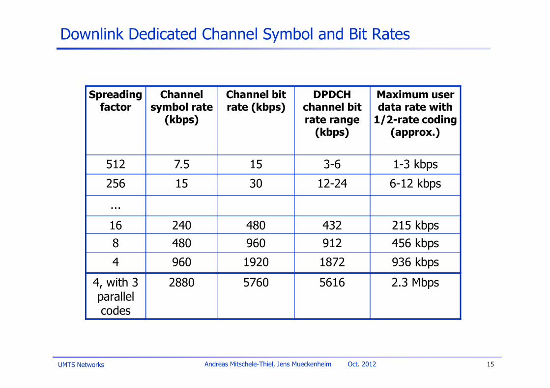
Downlink Dedicated Channel Symbol and Bit Rates
Spreadingfactor
Channelsymbol rate
(kbps)
Channel bitrate (kbps)
DPDCHchannel bitrate range
(kbps)
Maximum userdata rate with
1/2-rate coding(approx.)
512 7.5 15 3-6 1-3 kbps
256 15 30 12-24 6-12 kbps
...
16 240 480 432 215 kbps8 480 960 912 456 kbps
4 960 1920 1872 936 kbps
4, with 3parallelcodes
2880 5760 5616 2.3 Mbps

UMTS Networks 16Andreas Mitschele-Thiel, Jens Mueckenheim Oct. 2012
CDMA in Theory
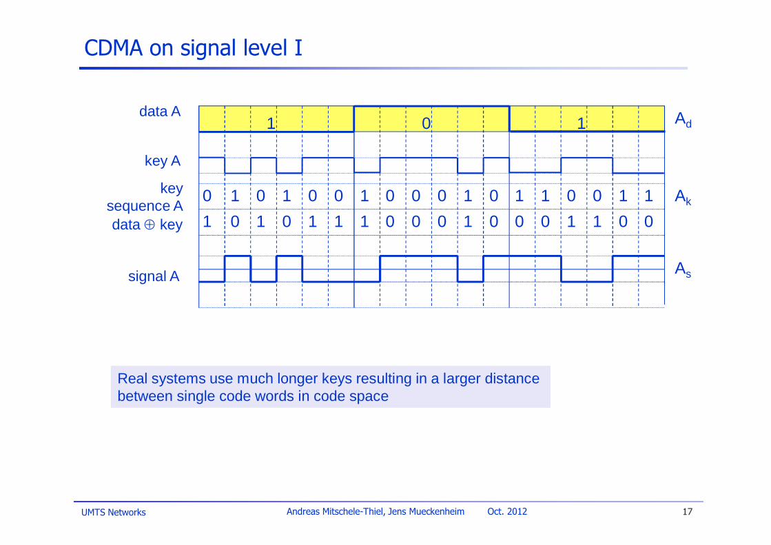
u Sender Au sends Ad = 1, code sequence Ac = 1010011 (assign: “0”= –1, “1”= +1)u sending signal As = Ad × Ac = (+1, –1, +1, –1, –1, +1, +1)
u Sender Bu sends Bd = 0, code sequence Bc = 0110101u sending signal Bs = Bd × Bc = (+1, –1, –1, +1, –1, +1, –1)
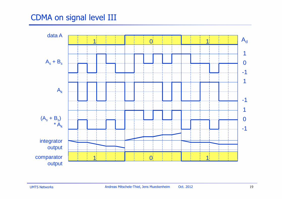
u Both signals superimpose in spaceu interference neglected (noise etc.)u As + Bs = (+2, –2, 0, 0, –2, +2, 0)
u Receiver wants to receive signal from sender Au apply sequence AC chipwise (inner product)
u Ar = (+2, –2, 0, 0, –2, +2, 0) · Ac = 2 + 2 + 0 + 0 + 2 + 2 + 0 = 8u result greater than 0, therefore, original bit was „1“
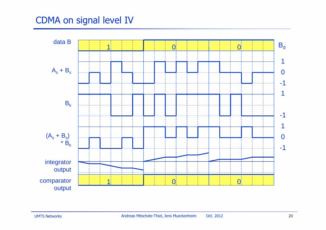
u receiving Bu Be = (+2, –2, 0, 0, –2, +2, 0) · Bc = –2 –2 + 0 + 0 – 2 – 2 + 0 = –8, i.e. „0“
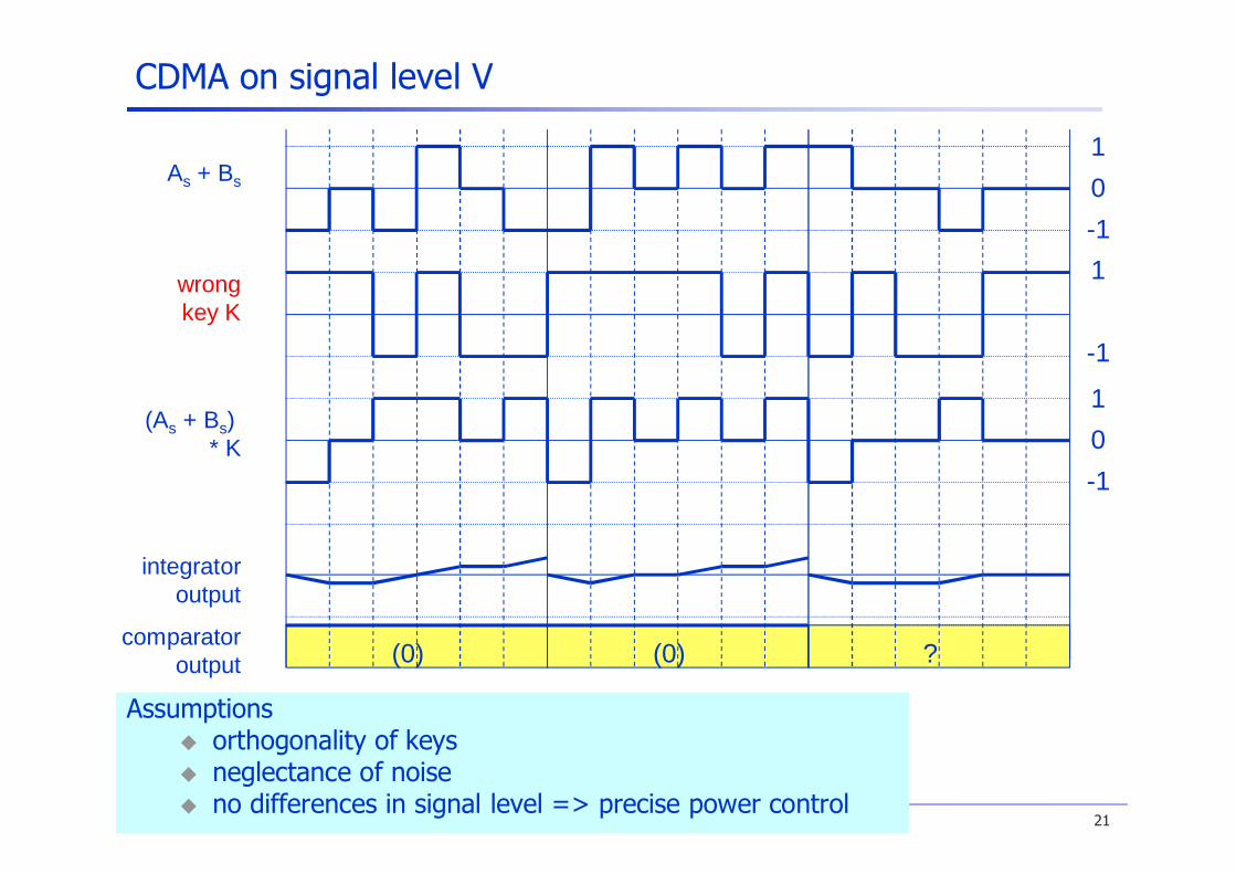
u wrong sequence CC = 1100110u Cr = (+2, –2, 0, 0, –2, +2, 0) · Cc = 0, decision impossible
UMTS Networks 17Andreas Mitschele-Thiel, Jens Mueckenheim Oct. 2012
CDMA on signal level I
data A
key A
signal A
data Å key
keysequence A
Real systems use much longer keys resulting in a larger distancebetween single code words in code space
1 0 1
10 0 1 0 0 1 0 0 0 1 0 1 1 0 0 1 101 1 0 1 1 1 0 0 0 1 0 0 0 1 1 0 0
Ad
Ak
As

UMTS Networks 18Andreas Mitschele-Thiel, Jens Mueckenheim Oct. 2012
CDMA on signal level II
signal A
data B
key Bkey
sequence B
signal B
As + Bs
data Å key
1 0 0
00 0 1 1 0 1 0 1 0 0 0 0 1 0 1 1 111 1 0 0 1 1 0 1 0 0 0 0 1 0 1 1 1
Bd
Bk
Bs
As
10-1
UMTS Networks 19Andreas Mitschele-Thiel, Jens Mueckenheim Oct. 2012
CDMA on signal level III
Ak
(As + Bs)* Ak
integratoroutput
comparatoroutput
As + Bs
data A
1 0 1
1 0 1 Ad
10-1
1
-1
10-1
UMTS Networks 20Andreas Mitschele-Thiel, Jens Mueckenheim Oct. 2012
CDMA on signal level IV
integratoroutput
comparatoroutput
Bk
(As + Bs)* Bk
As + Bs
data B
1 0 0
1 0 0 Bd
10-11
-110-1
UMTS Networks 21Andreas Mitschele-Thiel, Jens Mueckenheim Oct. 2012
comparatoroutput
CDMA on signal level V
wrongkey K
integratoroutput
(As + Bs)* K
As + Bs
(0) (0) ?
Assumptionsu orthogonality of keysu neglectance of noiseu no differences in signal level => precise power control
10-11
-1
10-1
UMTS Networks 22Andreas Mitschele-Thiel, Jens Mueckenheim Oct. 2012
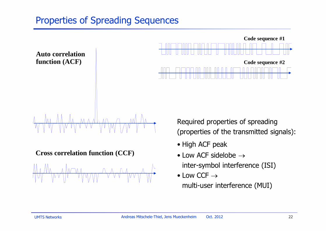
Properties of Spreading Sequences
Cross correlation function (CCF)
Auto correlationfunction (ACF)
Code sequence #1
Code sequence #2
Required properties of spreading(properties of the transmitted signals):
• High ACF peak• Low ACF sidelobe ®
inter-symbol interference (ISI)• Low CCF ®
multi-user interference (MUI)
UMTS Networks 23Andreas Mitschele-Thiel, Jens Mueckenheim Oct. 2012
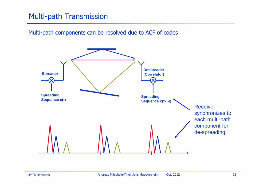
Multi-path Transmission
Multi-path components can be resolved due to ACF of codes
Spreader
SpreadingSequence c(t)
Despreader(Correlator)
SpreadingSequence c(t-Td)
Receiversynchronizes toeach multi-pathcomponent forde-spreading
UMTS Networks 24Andreas Mitschele-Thiel, Jens Mueckenheim Oct. 2012
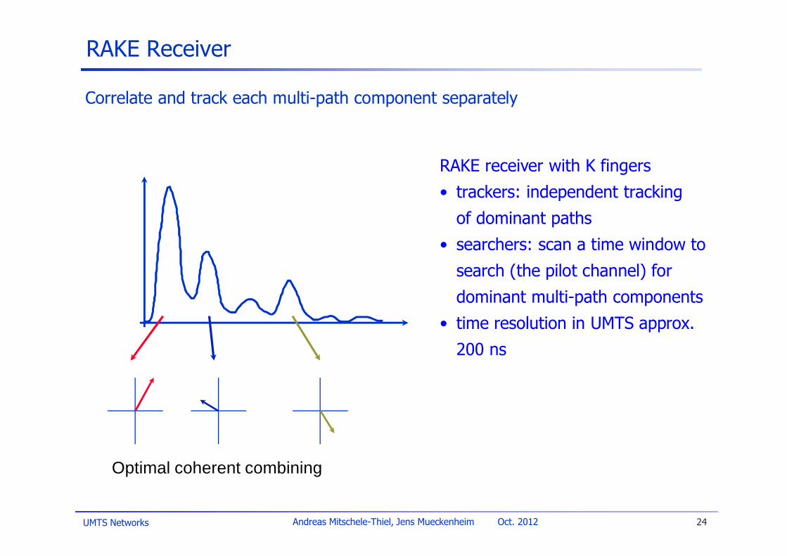
RAKE Receiver
Correlate and track each multi-path component separately
Optimal coherent combining
RAKE receiver with K fingers• trackers: independent tracking
of dominant paths• searchers: scan a time window to
search (the pilot channel) fordominant multi-path components
• time resolution in UMTS approx.200 ns
UMTS Networks 25Andreas Mitschele-Thiel, Jens Mueckenheim Oct. 2012
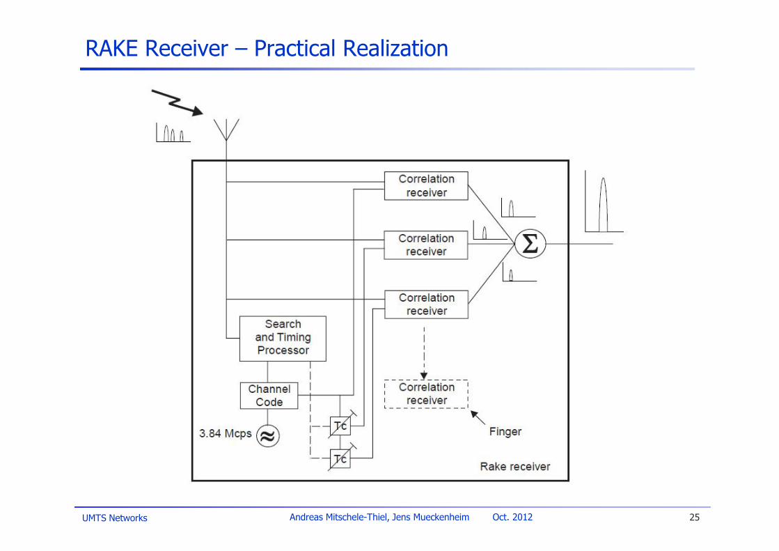
RAKE Receiver – Practical Realization

UMTS Networks 26Andreas Mitschele-Thiel, Jens Mueckenheim Oct. 2012
Macro-Diversity & Soft Handover
Optimal coherent combiningin the RAKE receiver (at MS)
NodeB 1NodeB 2
UE
UMTS Networks 27Andreas Mitschele-Thiel, Jens Mueckenheim Oct. 2012
Multi-user CDMA
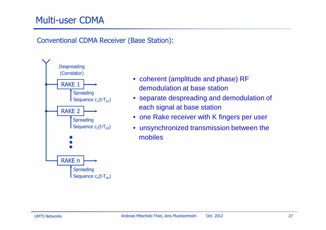
Conventional CDMA Receiver (Base Station):
• coherent (amplitude and phase) RFdemodulation at base station
• separate despreading and demodulation ofeach signal at base station
• one Rake receiver with K fingers per user• unsynchronized transmission between the
mobiles
Despreading(Correlator)
SpreadingSequence c1(t-Td1)
RAKE 1
SpreadingSequence c2(t-Td2)
RAKE 2
SpreadingSequence cn(t-Tdn)
RAKE n
UMTS Networks 28Andreas Mitschele-Thiel, Jens Mueckenheim Oct. 2012
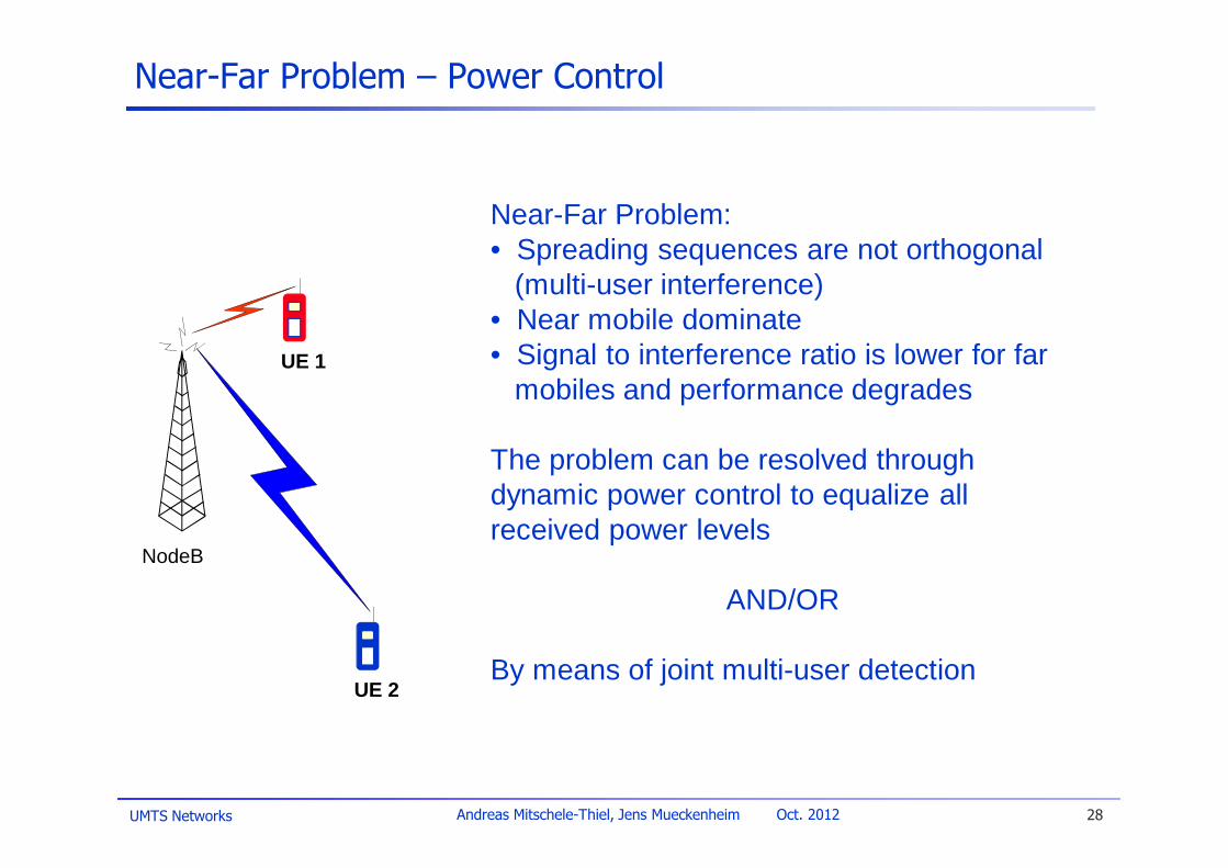
Near-Far Problem:• Spreading sequences are not orthogonal
(multi-user interference)• Near mobile dominate• Signal to interference ratio is lower for far
mobiles and performance degrades
The problem can be resolved throughdynamic power control to equalize allreceived power levels
AND/OR
By means of joint multi-user detection
Near-Far Problem – Power Control
NodeB
UE 1
UE 2
UMTS Networks 29Andreas Mitschele-Thiel, Jens Mueckenheim Oct. 2012
Interference Cancellation
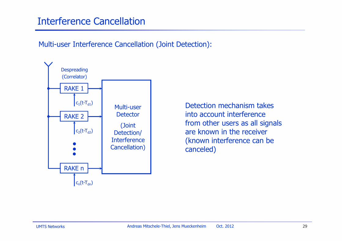
Multi-user Interference Cancellation (Joint Detection):
Detection mechanism takesinto account interferencefrom other users as all signalsare known in the receiver(known interference can becanceled)
Multi-userDetector
(JointDetection/
InterferenceCancellation)
Despreading(Correlator)
c1(t-Td1)
RAKE 1
c2(t-Td2)
RAKE 2
cn(t-Tdn)
RAKE n
UMTS Networks 30Andreas Mitschele-Thiel, Jens Mueckenheim Oct. 2012
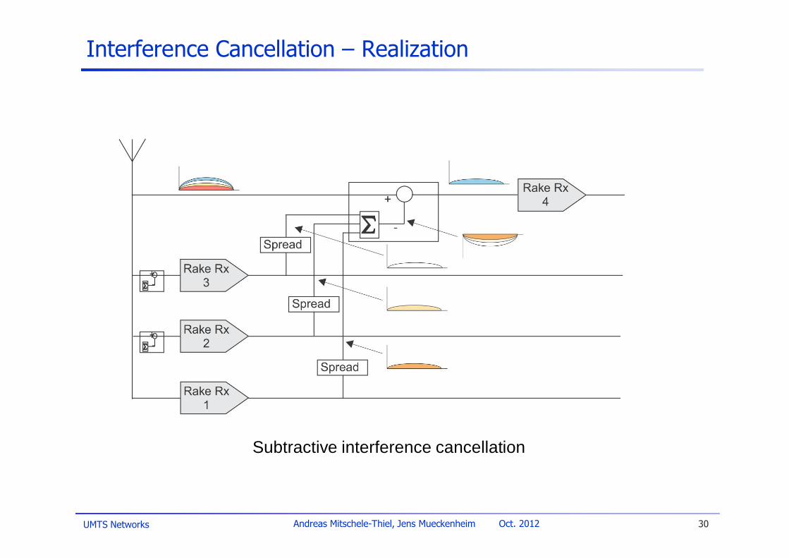
Interference Cancellation – Realization
Subtractive interference cancellation

UMTS Networks 31Andreas Mitschele-Thiel, Jens Mueckenheim Oct. 2012
FDD vs. TDD Mode
UMTS supports FDD and TDD
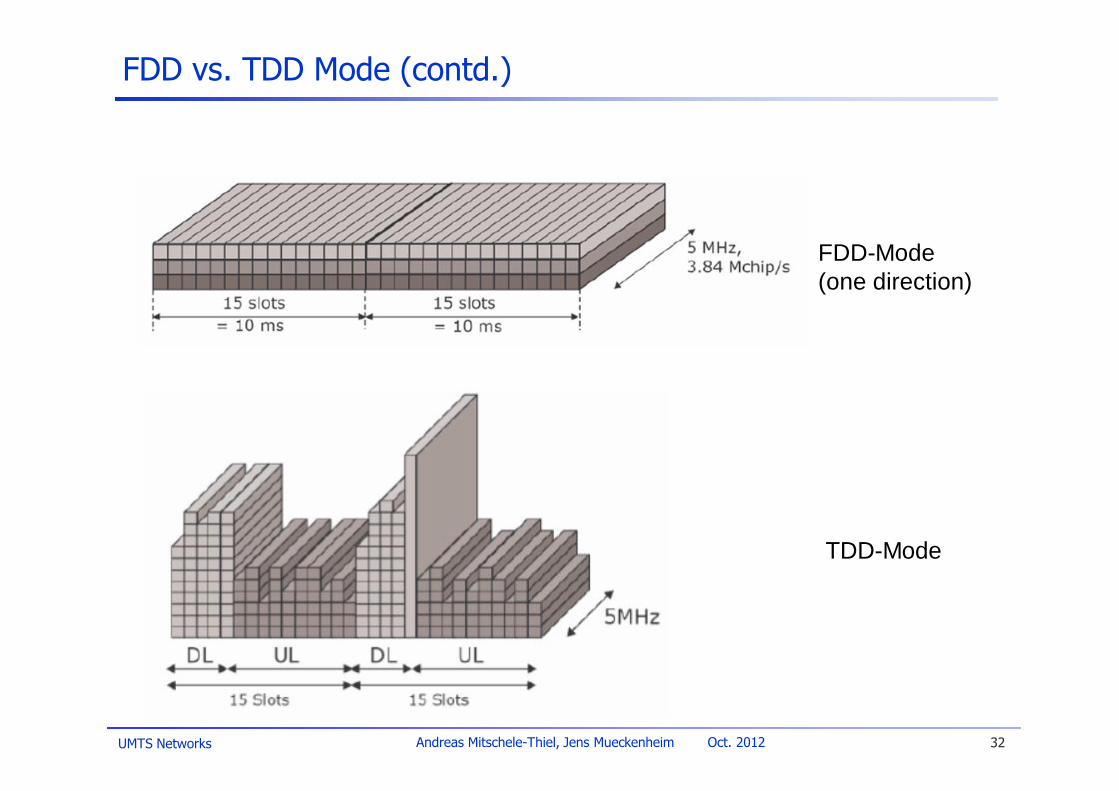
FDD mode:u Multiple access scheme: DS-CDMA (Direct Sequence-CDMA)u Symmetric capacity of up- and down-linku Better suited for low bit rate transmission in larger cells
(no timing advance, no synchronization from MS required)
TDD mode:u Multiple access scheme: TD-CDMA (JD-CDMA)u Asymmetric capacity allocation for up- and down-linku Strict synchronization required for MS (timing advance)u Relaxed power control and near-far resistance by the use of intra-cell
multi-user interference cancellation (spreading factor 1 - 16)
UMTS Networks 32Andreas Mitschele-Thiel, Jens Mueckenheim Oct. 2012
FDD vs. TDD Mode (contd.)
TDD-Mode
FDD-Mode(one direction)
UMTS Networks 33Andreas Mitschele-Thiel, Jens Mueckenheim Oct. 2012
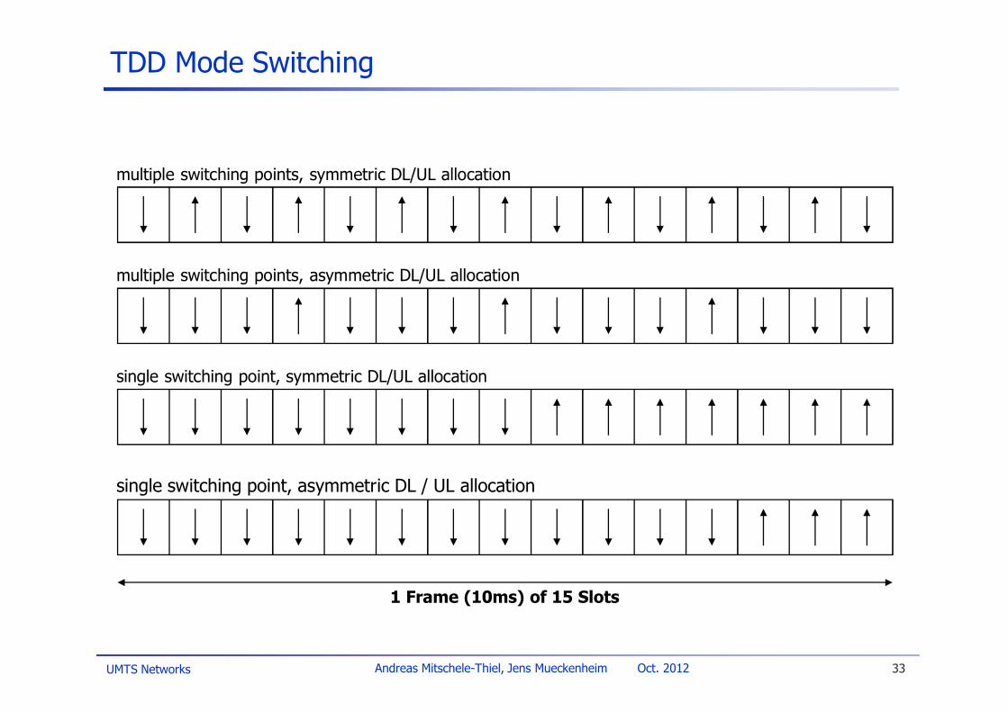
TDD Mode Switching
1 Frame (10ms) of 15 Slots
multiple switching points, symmetric DL/UL allocation
multiple switching points, asymmetric DL/UL allocation
single switching point, symmetric DL/UL allocation
single switching point, asymmetric DL / UL allocation

UMTS Networks 34Andreas Mitschele-Thiel, Jens Mueckenheim Oct. 2012
W-CDMA for UMTS – Summary of Key Parameters
Multiple-Access DS-CDMA (TD-CDMA)Duplex scheme FDD (TDD)
Chip rate 3.84 MChip/s(TDD: 1.28/ 3.84/ 7.68 MChip/s)
Carrier spacing Flexible in the range 4.6 – 5.0 MHz(200 kHz carrier raster)
Frequency bands 1920 – 1980 / 2110 – 2170 paired (FDD)1900 – 1920 and 2010 – 2025 unpaired (TDD)
Frame length 10 ms / (15 time slots)Inter-BSsynchronization
FDD mode: No accurate synchronization neededTDD mode: Synchronization needed
Multi-rate/Variable-rate scheme
Variable-spreading factor + Multi-codeSpreading factor: 4 – 256 (FDD) and 1 – 16 (TDD)
Channel codingscheme
Convolutional coding (rate 1/2 – 1/3)Turbo coding
UMTS Networks 35Andreas Mitschele-Thiel, Jens Mueckenheim Oct. 2012
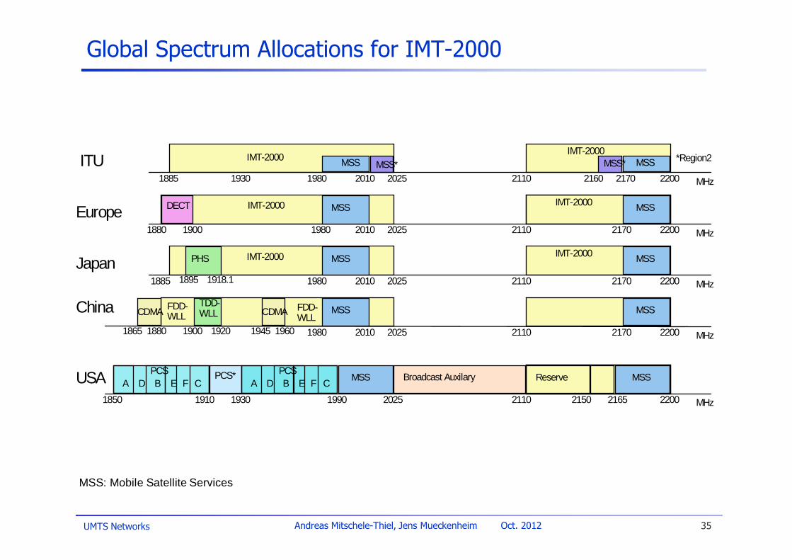
Global Spectrum Allocations for IMT-2000
ITU2010 20251980
MSS MSS*1930
IMT-2000 MSSMSS*IMT-2000
2160 2170 2200 MHz
*Region2
1885 2110
PHS
20101980 2025Japan
2110 22002170
IMT-2000 MSSMSSIMT-2000
18951885 1918.1 MHz
1980 2110 22002170
IMT-2000 MSS
19001880
DECT
2010
MSSIMT-2000
2025 MHz
Europe
2110 220021652150
Reserve MSSBroadcast Auxilary
1910 1930 1990 2025
MSS
1850
PCS*PCSA B CD E F
PCSA B CD E F
MHz
USA
20101980 2025
China2110 22002170
MSSMSS
1900 1920 MHz1865 1880 1945 1960
CDMA FDD-WLL
FDD-WLLCDMA
TDD-WLL
MSS: Mobile Satellite Services
UMTS Networks 36Andreas Mitschele-Thiel, Jens Mueckenheim Oct. 2012
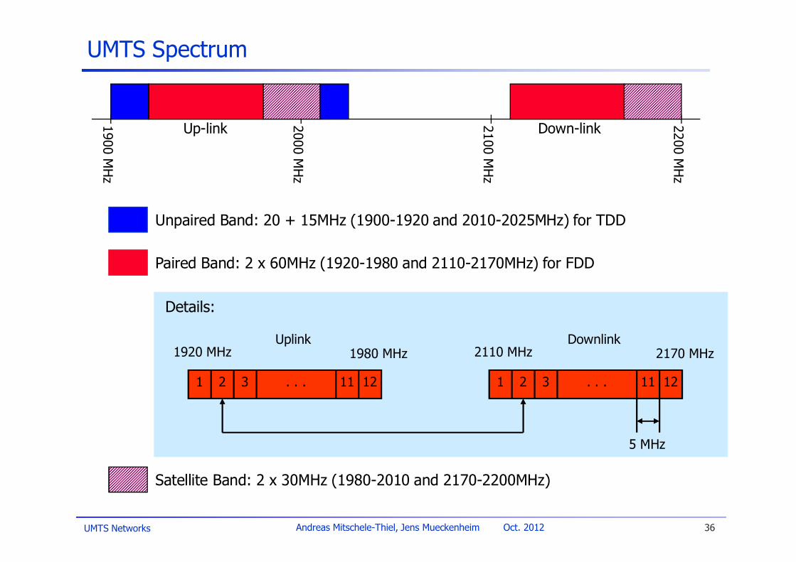
UMTS Spectrum
2200M
Hz
2000M
Hz
2100M
Hz
1900M
Hz
Unpaired Band: 20 + 15MHz (1900-1920 and 2010-2025MHz) for TDD
Paired Band: 2 x 60MHz (1920-1980 and 2110-2170MHz) for FDD
Up-link Down-link
Satellite Band: 2 x 30MHz (1980-2010 and 2170-2200MHz)
1 2 3 11 12. . .
1920 MHz 1980 MHz
1 2 3 11 12. . .
2110 MHz 2170 MHz
5 MHz
Uplink Downlink
Details:


