WARNING
Read and follow all safety
precautions in this Guide –
improper use can cause serious or
fatal injury.

Page 2
WARNING
Important Safety Precautions for Step and Touch Users
To avoid possible electrical shock or personal injury:
The SNT must be used and serviced only by qualified personnel
who have been thoroughly trained in its correct and safe use.
Users must be familiar with and exercise all possible high voltage
safety practices and adhere to local and national safety codes.
Do not rely only on the voltage measurement of the SNT. For
example, voltage changes can be too quick for you to react to even
if detected by the SNT or the probe may become disconnected just
as you approach the tower. The SNT must be used only to augment
and NEVER to supplant any safety equipment or practice.
The SNT is to be used ONLY to measure ground voltage differences
between a tower and the SNT ground rod with the power lines de-
energized. NEVER use this probe to measure high voltage on
power distribution systems.
Always install probe using a hot stick while taking all precautions
necessary to ensure worker safety (including, for example,
insulating gloves and boots).
After installing probe, check probe fault detection before
beginning work. See
Field Setup on page 7 for details.
Never use the SNT if the Check Probe or Battery Low indicators
display a fault. Never use the SNT if any component is damaged or
is not functioning properly.
Do not use the SNT if you are fatigued or otherwise impaired.

SNT Instrument User Guide Page 3
SNT BASICS
The Step and Touch (SNT) instrument continuously monitors and alarms
“Step and Touch” potential while transmission line crews are working in
the field, with safety features such as Lost Probe Connection and Low
Battery Warning.
The SNT kit includes a ground rod, a magnetic probe end and clamp
probe end.
ALARM RANGES
The SNT provides audible and visual alarm warnings if the probe voltage
is in a dangerous range. Each voltage range has a distinct pattern of
bright flashing LEDs and audible beeps (Sonalert):
Range (Volts) Instrument Actions
0 – 100 Green LEDs flash
101 – 499 Yellow LEDs flash, beeps every second
500+ Red LEDs flash rapidly, beeps rapidly
VOLTAGE
Displays the probe voltage intermittently (at least
every 5 sec).
Voltages below 10 are displayed as zero. Voltages
exceeding 999 are displayed as 999.
The information provided in this document does not cover all details or
every possible contingency encountered in relation to the operation or
maintenance of the SNT and is not intended to be a substitute for
adequate training and experience.

Page 4
SNT BASICS
SONALERT
Loud audio alert (90 dB at 2 ft.)
FAULT MODE
The Red and Yellow LEDs flash and the
Sonalert sounds. Fault Mode is caused by a
lost probe or ground connection, or a low
battery.
Fault Mode automatically clears when the
fault condition is corrected.
Do not use the SNT if Fault Mode is active.

SNT Instrument User Guide Page 5
SNT BASICS
CHECK PROBE FAULT
If the probe or ground connection has been lost, this
fault LED will be on, and Fault Mode will be activated.
In normal mode, the SNT checks the connection every
60 seconds. When the Check Probe LED is on, the SNT
checks the connection every 3 seconds.
Do not use the SNT if the Check Probe LED is on. Always check probe
fault detection before use. See page 7 for details.
BATTERY LOW FAULT
When battery voltage is low, the Battery Low LED will
be on and the probe voltage will not be automatically
displayed. Probe voltages can still be displayed by
pressing Read Meter.
If battery is too low, Fault Mode will be activated. See
page 13 for details.
Do not use the SNT if the Battery Low LED is on.

Page 6
INSTRUMENT BUTTONS AND INDICATORS
Press to turn the SNT on. All the LEDs will flash, and the Sonalert will beep. If the LEDs fail to flash, or the Sonalert fails to beep, do not use the SNT.
Press to turn the SNT off. The display will beep once and flash “OFF” twice.
Press to display the probe voltage.
Press to display the battery voltage. See page 13 for more details.
Press to test the LEDs and the Sonalert. All the LEDS should flash and the Sonalert will beep.
Press to silence the Sonalert and clear alarms. If the error condition still exists, pressing Clear Alarm will silence the Sonalert, but not clear the alarm LEDs.
Red when charging, green when charging is complete. Avoid overcharging.
Notes:
The probe voltage is not measured while any button is pressed.
The SNT will not power on if it’s being charged.

SNT Instrument User Guide Page 7
FIELD SETUP
1. Drive Grounding Stake
a. Assemble the two halves of the grounding stake.
b. Use the slide hammer to drive the stake into the earth. DO NOT
strike the top of the stake with any device.
2. Connect Probe Cable to SNT and attach to Grounding Stake
a. Plug the yellow probe cable into the SNT’s Probe+ connector.
b. Slide the grounding connector on the back of the SNT over the
top of the stake. Or, connect jumper cables between the ground
stake and the grounding connector on the back of the SNT.
3. Ready the Probe End (Magnetic Probe or Clamp Probe)
a. Plug the red connector from the yellow probe cable assembly
into the probe end (clamp or magnetic).
b. If using the clamp probe, open the clamp, point it down, then
release to lock the jaws in the preloaded position.
c. Attach the probe end to a hot stick.
d. Carefully place the probe end on the SNT carrying case or some
other surface isolated from earth ground.
4. Check Probe Fault Detection
a. Verify the probe cable’s red wire is not contacting earth ground.
b. Press Power On to turn on the SNT. The LEDs should flash and
the Sonalert beep. If not, do not use the SNT.
c. Wait up to 90 sec. for Check Probe to illuminate and Fault Mode
to activate (Red and Yellow LEDs flash and Sonalert sounds).
5. Attach Probe End (Magnetic Probe or Clamp Probe)
a. With Fault Mode active, attach the probe end to a tower leg,
pole or other probing point as directed by the crew supervisor.
b. Fault Mode should deactivate within 3 seconds and the Check
Probe LED should clear.
c. If the Check Probe fault continues, either the probe end or
grounding stake is not making a proper connection.
Note: Close case after setup—do not allow moisture to collect.

Page 8
GROUND ROD ILLUSTRATION
Determine the best location for the reference ground stake and drive it
into the earth using the slide hammer.
DO NOT STRIKE THE TOP OF THE STAKE WITH ANY DEVICE.
Slide the instrument’s grounding connector over the top of the stake.
Mounted SNT
Driving Ground Stake
SNT Instrument User Guide Page 9
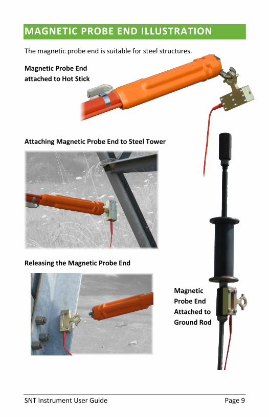
MAGNETIC PROBE END ILLUSTRATION
The magnetic probe end is suitable for steel structures.
Magnetic Probe End
attached to Hot Stick
Attaching Magnetic Probe End to Steel Tower
Releasing the Magnetic Probe End
Magnetic
Probe End
Attached to
Ground Rod

Page 10
CLAMP PROBE END ILLUSTRATION
The clamp is well-suited for aluminum structures and round rods.
Preloaded Clamp
Clamp is shown “preloaded”.
This is done by holding it upside
down, squeezing the handles to
let the jaws flop into position,
then releasing the handle.
Attaching Clamp to Steel
or Aluminum Tower
Attaching Clamp to Ground Rod

SNT Instrument User Guide Page 11
FIELD USE
When the voltage is 100 V or less, the voltage will be
displayed every 5 seconds.
When the voltage is between 101 and 499, the
voltage will be displayed every 1 second.
When the voltage is 500 V or greater, it will be displayed rapidly.
Voltages below 10V are not displayed. Voltages above 999 are displayed
as 999.
IF AN ALARM OCCURS
The alarms are “latched”. Once an alarm occurs, it will remain active,
even if the probe voltage falls below the alarm threshold.
If an alarm occurs:
1. Follow established procedures as directed by your crew
supervisor.
2. Once you are ready to clear the alarm, press the Clear Alarm
button. The alarm will clear if the underlying error condition has
cleared. If the underlying error condition is still present, the
Sonalert will be silenced, but the visible LED alarms will
continue.
Page 12
PACKING UP
1. Turn SNT Off
Press Power Off.
2. Remove Probe End
a. Remove the probe end from the tower leg or other probing
point as directed by your crew supervisor.
b. Disconnect the red plug from the probe end.
3. Remove SNT
a. Lift the SNT from the ground stake. To extend the connector’s
life, do not twist or lift it at an angle.
b. Set the instrument down on its foam cutout. This will help keep
the SNT ground connection clean by making sure it does not sit
on a dirty surface such as sand, soil, or rocks.
4. Remove Grounding Stake
a. Use the grounding stake’s slide hammer to help remove it.
b. Pack up the probe end and grounding stake in the bottom of the
case.
5. Place in Case
a. Place the instrument, cable and its foam back in the case.
b. Close the lid and close the latches.
Note: All items must be packed correctly into the foam cutouts to
prevent damage during transport.

SNT Instrument User Guide Page 13
BATTERY
VOLTAGE
Press the Read Battery button to check the battery voltage. The
nominal voltage is 7.2V. A fully charged battery will measure greater
than 7.2V. The Low Battery LED will flash when the voltage is between
6.2 and 7.0V. Fault mode will activate between 6.0 and 6.2V. At 6.0 V,
the SNT will turn off.
CHARGING
Charge the SNT using the AC adapter, or using the 12V lighter adapter. If
fully discharged, charging time can take up to 2.5 hours.
Time between battery charges depends on temperature and usage.
Typically, a charge will last 60 hours. At temperature extremes it can be
down to 12 hours.
The SNT cannot be charged while in use. Avoid overcharging.
Page 14
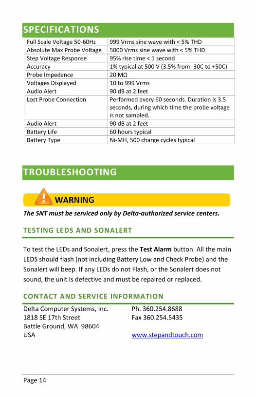
SPECIFICATIONS Full Scale Voltage 50-60Hz 999 Vrms sine wave with < 5% THD
Absolute Max Probe Voltage 5000 Vrms sine wave with < 5% THD
Step Voltage Response 95% rise time < 1 second
Accuracy 1% typical at 500 V (3.5% from -30C to +50C)
Probe Impedance 20 MΩ
Voltages Displayed 10 to 999 Vrms
Audio Alert 90 dB at 2 feet
Lost Probe Connection Performed every 60 seconds. Duration is 3.5 seconds, during which time the probe voltage is not sampled.
Audio Alert 90 dB at 2 feet
Battery Life 60 hours typical
Battery Type Ni-MH, 500 charge cycles typical
TROUBLESHOOTING
The SNT must be serviced only by Delta-authorized service centers.
TESTING LEDS AND SONALERT
To test the LEDs and Sonalert, press the Test Alarm button. All the main
LEDS should flash (not including Battery Low and Check Probe) and the
Sonalert will beep. If any LEDs do not Flash, or the Sonalert does not
sound, the unit is defective and must be repaired or replaced.
CONTACT AND SERVICE INFORMATION
Delta Computer Systems, Inc. 1818 SE 17th Street Battle Ground, WA 98604 USA
Ph. 360.254.8688 Fax 360.254.5435 www.stepandtouch.com

SNT Instrument User Guide Page 15
SNT-02 KIT
PART DESCRIPTION PART NUMBER
Complete SNT-02 Kit SNT A020
Instrument SNT A005
Probe Cable SNT A006
AC Charging Adapter SNT E001
12V Lighter Charging Adapter SNT E002
Grounding Stake Assembly SNT A004
Clamp Probe SNT A002
Magnetic Probe SNT A003
Spare Probe Parts Kit SNT A007
User Guide SNT D001
HISTORY OF THE SNT INSTRUMENT
The SNT was originally designed by engineers at the Bonneville Power
Administration and was built by Delta Computer Systems, Inc. to BPA
specifications.
A number of these instruments have been in operation since the early
2000’s by BPA. BPA is a leader in step and touch potential awareness
and this product demonstrates that leadership.

Ver. 1.7, Apr 2015


