
Web‐Scale Data Management
4 Virtualization4. Virtualization
Wolfgang Lehner and group….

Coarse Grained ClassificationCoarse‐Grained ClassificationBig DataBig Data
PBs of data, 102‐105 nodes
OperationalHigh qps, a few rows/op
e g BigTable Dynamo PNUTS
AnalyticLow qps, billions of rows/opMapReduce Hadoop Dryad
12
e.g., BigTable, Dynamo, PNUTS MapReduce, Hadoop, Dryad
Virtualization(Scalability)
Multi‐Tenancy Machine Virtualization34 Multi TenancyMap N logical systems into 1
physical system
Machine VirtualizationMap 1 logical system into N physical
systems
2

Fine Grained ClassifcationFine‐Grained Classifcation
• Virtualization– Goals and Trends
• Machine Virtualization
• Storage Virtualization– Impact on Database Systemsp y
• Database Systems in Virtual Environments
C l i• Conclusion

it‘s simple!... it s simple!

VIRTUALIZATION ...is everywhere!

Example IExample I

Example IIExample II

Example IIIExample III

Example IVExample IV

Example VExample V

• “Any problem in computer science can be l d i h h l f i di i ”solved with another layer of indirection.”
(David Wheeler)

STATE OF THE ART COMPUTING CENTERS

Microsoft Massive Data CenterMicrosoft Massive Data Center
Northlake, Illinois (US)


MOTIVATION

A typical scenario in data centersA typical scenario in data centers
i R i tRequirements
• Response time < 2s
• Throughput > 100 rq/sec
Requirements• Response time < 5s
• Throughput > 50 rq/sec
Customer A Customer BPay 100$
Throughput > 100 rq/sec
Pay 50$
Run auction site Run trading site
16Shared Data Center
16

Hosting applicationsHosting applications
E mail Web DatabaseE‐mail serverLinux
Web serverLinux
Database serverLinuxLinux Linux Linux
Data Center
17
Common idiom: One‐to‐one mapping of applications to nodes17

Solution: VirtualizationE‐mail serverserverLinux
Web server
E‐mail serverLi
Web serveri
Database serverLi
Consolidate
serverLinux Virtualization
Linux Linux Linux
Database serverserverLinux
18
Improved utilization using consolidation18

Problem – Poor utilizationProblem Poor utilization
4
5
s
Wasted Resources
3
4
er of C
PUs
2Num
be
1
0
Time (every 5 mins)
Ad h ll i h19
Ad‐hoc resource allocation schemes waste resources19

INTRODUCTION

What is Virtualization?What is Virtualization?
h b f f h• Separating the abstract view of computing resources from the implementation of these resources
• A layer of indirection between abstract view and implementation of y presources– Hides implementation details
Controls mapping from abstract view to implementation– Controls mapping from abstract view to implementation
– Adds flexibility and agility to the computing infrastructure
– Can be used to solve many problems related to provisioning, manageability, security, …
– lower TCO, fewer computing resources
• “Virtualization will be a $20 billion market by 2010.” (IDC, Jan 2007)Virtualization will be a $20 billion market by 2010. (IDC, Jan 2007)
21

What can be virtualized the big fourWhat can be virtualized – the big four.
22

Virtual MachinesVirtual Machines
23

Virtual StorageVirtual Storage
24

Why virtualization?Why virtualization?
Vi t li ti dd fl ibilit d ilit t th• Virtualization adds flexibility and agility to the computing infrastructure
• Can be used to solve many problems related to• Can be used to solve many problems related to– provisioning, manageability, security, …Pool and share computing resource– Pool and share computing resource
– Simplify administration and management– Improve fault toleranceImprove fault tolerance
• For organizations: Lower total cost of ownership for computing infrastructurefor computing infrastructure– Fewer computing resources– More resilient and simpler to managep g
25

What does Virtualization enable IWhat does Virtualization enable I
S lid i• Server consolidation– The vast majority of server are grossly underutilized
l d h l– Typical setup today: one machine per application (DBMS, web server, mail server, …)Provisioned for peak load Usually under utilized– Provisioned for peak load. Usually under‐utilized
– Instead, can run multiple applications on virtual machines that share the same physical machinemachines that share the same physical machine
– Reduces both CapEx (Capital EXpenditure) and OpEx(Operational EXpenditure)(Operational EXpenditure)
– Save hardware costs, administration costs, power, etc.
26

What does Virtualization enable IIWhat does Virtualization enable II
• S lid ti• Server consolidation
e ments
P1 e ments P2
Resource
requ
irem 1
Resource
requ
irem
Time Time
• Consolidate into a single machine with capacity P12– P12 < P1 + P2
Easier to manage
Time Time
– Easier to manage– Less total capacity and operating costs than original two
• Better utilization than the original two
27

What does Virtualization enable IIIWhat does Virtualization enable III
• Migration of VMs (both storage and CPU/memory)– Enables live load balancing
– Facilitates maintenance
Migrate VM
AppVM
to Machine 2(live migration)Need to bring Machine 1
down for maintenance
VMApp
Can now bring Machine 1
Machine 1 Machine 2(spare)
Can now bring Machine 1Down without serviceinterruption
Shared Storage
(spare)
28

What does Virtualization enable IVWhat does Virtualization enable IV
• High availability– Allows a small number of generic servers to back up all servers
VMDetect failure(heartbeat) VM
AppVM (heartbeat) VM
App
Restart VM on Machine 2 from image on sharedstorage
Machine 1 Machine 2(stand by)
g
Image of VMVM
Shared StorageVM
App29
TerminologyTerminology
E l ti• Emulation– Simulate complete hardware, allowing unmodified OS for different CPU to be runfor different CPU to be run
– Must simulate each instruction so slow– Example: BochsExample: Bochs
• Operating system virtualization– Isolated virtual servers within a serverIsolated virtual servers within a server– Guest and host OS use the same kernel– Example: Solaris Containers, Virtuozzo
• We discuss native virtualization or full virtualization
30

MACHINE VIRTUALIZATION

Machine Virtualization IMachine Virtualization I
A i t l hi " b t t " th ti• A virtual machine "abstracts" the computing resources of a physical machine into virtual resourcesresources
• Introduces a level of indirection between virtual resources and physical resourcesresources and physical resources
• End users only see the virtual resources– Can install their operating systems and run theirCan install their operating systems and run their applications on the virtual machines
• A Virtual Machine Monitor (or Hypervisor) is a ( yp )software layer that implements the mapping from virtual resources to physical resources
32

Machine Virtualization IIMachine Virtualization II
• Strong isolation between virtual machines• Flexible mapping between virtual resources andphysical resources
h l h h• Can have more virtual resources than the corresponding physical resources
• Can reallocate physical resources among VMsP h k i t d i t i t l• Pause, resume, checkpoint, and migrate virtualmachines
33

Virtualization HistoryVirtualization – History• Technique with long history (since the 1960's)
– Prominent since IBM 370 mainframe series
• Virtualization todayl– Larger scale
– Commodity hardware and operating systems
• Example Technologies• Example Technologies– IBM System Z/VM and IBM PowerVM on the Power Systems
– Sun X/VM and Zones/
– HP VM
– On the X86 processors• Xen and XenServer, Microsoft Hyper‐V, KVM, VMware ESX
34

Operating systemsOperating systems
• Run VMM in privileged mode, OS in user mode
• Privileged operations by the OS will trap
• Trap handler in VMM emulates these operations as if they were run on the virtual machine
35

Trap and Emulate Virtualization ITrap‐and‐Emulate Virtualization I
• Run VMM in privileged mode
• Run OS in user modeRun OS in user mode
• Privileged operations by the OS will trap
• Trap handler in VMM emulates these operations as if they were run on the virtual p ymachine
N i il d ti d• Non‐privileged operations can proceed as before with no intervention from the VMM
36

Trap and Emulate Virtualization IITrap‐and‐Emulate Virtualization II
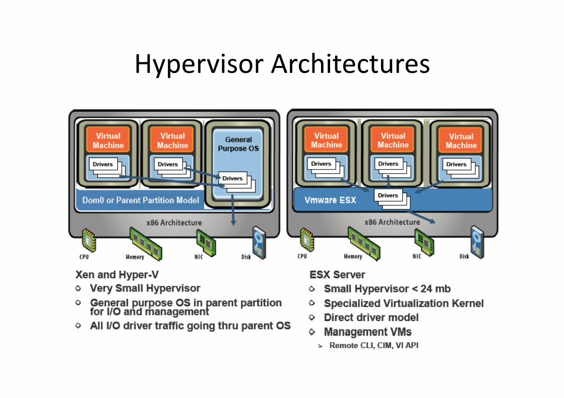
Hypervisor ArchitecturesHypervisor Architectures

more features...more features
• Bi T l ti f G t C d• Binary Translation of Guest Code– Translate guest kernel code– Replace privileged instrs with safe “equivalent” instruction sequences– No need for traps– Permits any unmodified x86 OS to run in a VM
(can virtualize any instruction set)• Virtualization Hardware Assist
– recent CPUs have features to reduce someof the overhead at the monitor level
– does not remove all virtualization overheads– scheduling, memory management and I/O
are still virtualized with a software layer– The Binary Translation monitor is faster
than hardware‐assist for many workloads
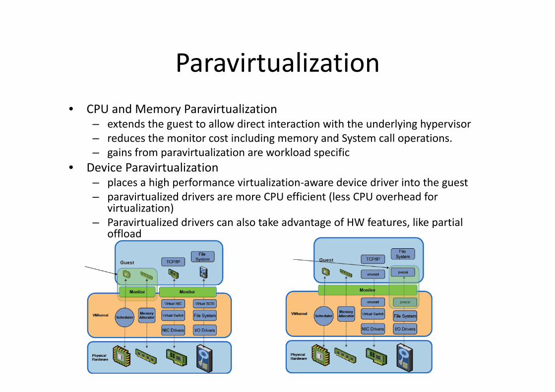
ParavirtualizationParavirtualization• CPU and Memory Paravirtualization• CPU and Memory Paravirtualization
– extends the guest to allow direct interaction with the underlying hypervisor– reduces the monitor cost including memory and System call operations.
gains from paravirtualization are workload specific– gains from paravirtualization are workload specific• Device Paravirtualization
– places a high performance virtualization‐aware device driver into the guestparavirtualized drivers are more CPU efficient (less CPU overhead for– paravirtualized drivers are more CPU efficient (less CPU overhead forvirtualization)
– Paravirtualized drivers can also take advantage of HW features, like partial offload

Virtual Machines:Usage and Repositories
• Software development and testing– Multiple environments pfor development and testing
• Software deploymentPreconfigured virtual– Preconfigured virtual appliances
Repositories of virtual– Repositories of virtual appliances on the web
41

Why not Use Virtualization?Why not Use Virtualization?
• Performance penalty– Indirection through VM adds overheadg
– Can be reduced through better virtualization supportsupport
• Hiding details of physical resources– Some applications (e.g., DBMS!) make decisions based on assumptions about the physical resources
42

... some numbers(SQL Server within VMware)

some (more) numbers... some (more) numbers
PH HDFS VM HDFS ith• PH‐HDFS vs VM‐HDFS with different data scale and 7 nodes cluster
• PH‐HDFS vs VM‐HDFS with different cluster scale withdifferent cluster scale, with the same data distribution (512MB per DataNode)
• PH‐HDFS vs VM‐HDFS with different throughputdifferent throughput (requests/s) and 7 nodes cluster

still more numbers... still more numbers
• WordCount example • Sort and wordcountexecution with different VM load per node, and different data size

STORAGE VIRTUALIZATION

Spectrum of Storage VirtualizationSpectrum of Storage Virtualization

Storage VirtualizationStorage Virtualization
• Storage virtualization is a layer of indirection that allows the definition of virtual storage gdevices
• Basis Operations• Basis Operations– create, destroy physical devices
– grow, shrink virtual devices
– change properties RAID mirrorg p p• size, performance, reliability
48virtual devices

Why Storage Virtualization?Why Storage Virtualization?
/• Minimize/avoid downtime– transparent redundancy
I f• Improve performance– Distribution and balance storage load
– Dynamic storage provisioningDynamic storage provisioning
– control placement
• Reduce cost of storage administrationg
physical storagepool
virtual devices
Application 1 Application 2 Application 1 Application2

Additional CapabilitiesAdditional Capabilities
File System Level• Versioning, snapshots, point‐
i i i
Database Level• Storage snapshots and versioning
backup and recoveryin‐time copies• Local and remote mirroring• Migration of virtual devices
– backup and recovery– concurrent applications
• Storage replication and mirroringdynamic DBMS provisioningMigration of virtual devices
– supports provisioning, hierarchical storagemanagement
– dynamic DBMS provisioning• Dynamic storage resource
allocation– accommodate workloadmanagement
• Auto‐administration– policy‐based management
accommodate workloadfluctuations
– e.g., resizable tablespaces• CPU and memory in the storage
• Storage QoS and performance isolation
system– caching– offload DBMS functions
50

What Does StorageVirtualization Enable?
• Consistent Interface for All Storage Applications
• Non‐disruptive LUN Creation, Expansion, Deletionp , p ,
• Non‐disruptive Data Consolidation, Data MigrationMigration
• Non‐disruptive RAID Level Changes
• Tiering of Storage Using Heterogenous Storage
• Replication Across Heterogenous StorageReplication Across Heterogenous Storage
• Backup/Restore, Archival, Thin Provisioning, etc
51
Storage Virtualization andDBMS‐Tuning I
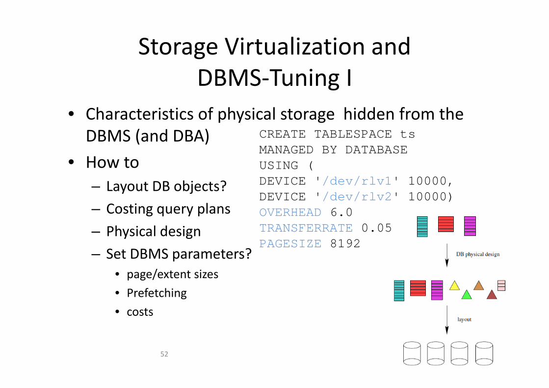
• Characteristics of physical storage hidden from theDBMS (and DBA) CREATE TABLESPACE ts
MANAGED BY DATABASE• How to
– Layout DB objects?
MANAGED BY DATABASEUSING (DEVICE '/dev/rlv1' 10000,DEVICE '/d / l 2' 10000)
– Costing query plans
– Physical design
DEVICE '/dev/rlv2' 10000)OVERHEAD 6.0TRANSFERRATE 0.05y g
– Set DBMS parameters?• page/extent sizes
PAGESIZE 8192
• Prefetching
• costs
52

Storage Virtualization andDBMS‐Tuning II
should not be there!!!
53
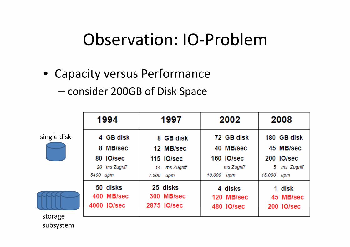
Observation: IO ProblemObservation: IO‐Problem
• Capacity versus Performance– consider 200GB of Disk Spacep
single disk
storagesubsystem

Observation 2: System designObservation 2: System design
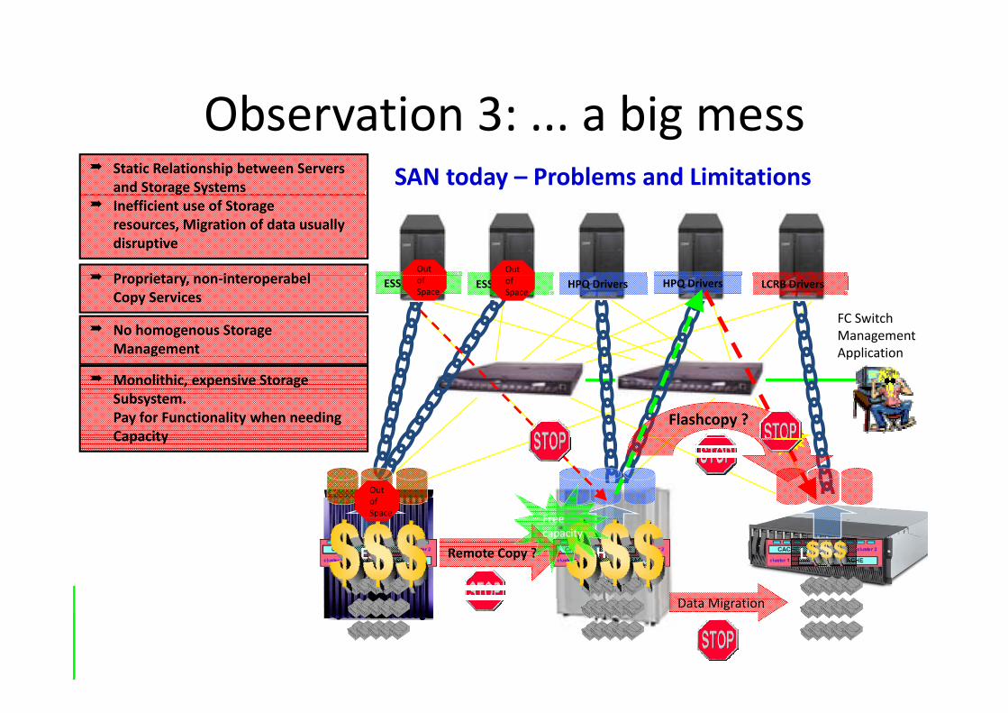
Observation 3: a big messObservation 3: ... a big mess Static Relationship between Servers
and Storage Systems SAN today – Problems and Limitations
P i t i t b l
Inefficient use of Storageresources, Migration of data usually disruptive
Out Out
FC SwitchManagementApplication
ESS Drivers ESS Drivers HPQ Drivers HPQ Drivers LCRB Drivers Proprietary, non‐interoperabelCopy Services
No homogenous Storage Management
ofSpace
ofSpace
Application
Flashcopy ?
Monolithic, expensive StorageSubsystem.Pay for Functionality when needing CapacityCapacity
OutofSpace Free
HPQ LCRBESS Remote Copy ?
Freecapacity
010101010101010101D t Mi ti010101010101010101010010101101001000Data Migration

End to End Physical Design IEnd‐to‐End Physical Design I
• Goal– Solve both DB design and storage design problems while preserving
virtualizationvirtualization.
• Two approaches1. export virtual device characteristics to DBAp
• weakens virtualization
• DBA/DBMS must model I/O costs
DBA i l d i l t• DBA involved in layout
2. describe DBMS storage workload to storage administrator• storage virtualization preservedg p
• storage administrator responsible for layout
• need to estimate DBMS storage workload
• can accommodate multiple storage clients• can accommodate multiple storage clients
57

End to End Physical Design IIEnd‐to‐End Physical Design II
1. Ignore problem interdependency: DB design, then storage system design
2 E l it i ti d i t l2. Exploit existing design tools
3. Predict storage workload at design time
58
Storage Virtualization
VIRTUAL DISKStorage Virtualization

Shared Disk SystemsShared‐Disk Systems
• Architecture– Many computing nodes, one shared disk system
Multiple database instances (one on each node) accessing the same– Multiple database instances (one on each node) accessing the same database over shared storage and act as a single “clustered” server.
Grid Cluster4 x 4 CPUs
Grid Cluster
Fibre Channel SAN Switches
4 x 16 GB RAM16 FC‐AL Controller
8 x 14 disks16 FC‐AL Controller1600MB/sec throughput…
Shared Disk System

Shared Disk Systems (2)Shared‐Disk Systems (2)
Ad t• Advantages– 100 % node utilization possible– All data is accessible even if one node/multiple nodes fail(s)/ p ( )– Provides facility for incremental growth
• DisadvantagesI d h i i ( h h )– Inter‐node synchronization (cache coherence) is required and involves complex lock management
– OS overhead for running shared disk software– Increased cost
• Database vendors and features• Database vendors and features– Oracle Real Application Cluster (Oracle RAC)– DB2 on OS/390 Cluster

SUN ORACLE Database MachineSUN ORACLE Database Machine
• Cell Server provide „virtual blocks“

SUN ORACLE Database MachineSUN ORACLE Database Machine

Storage Virtualization
MULTI‐TIER CACHINGStorage Virtualization

Multi Tier CachingMulti‐Tier Caching
• Exploit memory in the storage system
• Both the DBMS and the storage system rely onBoth the DBMS and the storage system rely on caching
Wi h di i h i• Without coordination, caches can interactbadly
65

Example Two Tier CachingExample – Two‐Tier Caching
1. p misses tier‐one cache, requested from tier‐two
2 i ti t h2. p misses tier‐two cache, fetched from device
3 p placed into tier two cache3. p placed into tier‐two cache
4. p placed into tier‐one cache
Cache Inclusion
i i b th h Thi i th• p is in both caches. This is thecache inclusion problem.
66

Locality of 2nd Tier WorkloadsLocality of 2nd Tier Workloadsgood temporal locality weak temporal locality
Client ServerClient Server
67

Write HintsWrite Hints
• Why does tier 1 WRITE?1. Replacement: clean a block so that it can be replaced
2 Recovery: clean a block to limit potential data loss or2. Recovery: clean a block to limit potential data loss or
• Recovery effort– a write hint identifies the reason for a WRITEa write hint identifies the reason for a WRITE
– help to distinguish the good opportunities from the bad
– replacement vs. Recovery
– synchronous vs. Asynchronous
• Tier two interprets write hints to guide caching decisionsASYNCH SYNCH
REPLACE eviction likely soon eviction imminent
RECOV uncertain uncertain
68

Storage Virtualization
HETEROGENOUS MEMORYStorage Virtualization

Example 1: Archiving & BackupExample 1: Archiving & Backup
dl h d d diff l• Handle hot and warm data differently• Storage systems knows about a „databaseg yapplication“– assumes abstract entities independent of anyassumes abstract entities independent of anyspecific system
– tables, table spaces, log files, and control filestables, table spaces, log files, and control files
• Backup/Archivingmore than just the– more than just thedatabase!


Disk Mirroring and Online BackupDisk Mirroring and Online Backup
• Di k Mi i• Disk Mirroring– Properties
• copes with media errorsti ll i ll l• sequentially or in parallel
– Restore• have to resynchronize mirrors
(may take a very long time)(may take a _very_ long time)– Alternative (Oracle)
• multiplexing of redo logfiles and control files• allows for multiple destinations of archive log filesp g
• Online backup – use log files during the recovery process to recover the database to a
fully consistent statefully consistent state– requires to retain the RDBMS log files– the system has to figure out where to start recovery

Example Tivoli Storage ManagerExample Tivoli Storage Manager• back up the raw devices directly; the database must be offline during an image• back up the raw devices directly; the database must be offline during an image
backup for consistency. • back up the data to files, and then use Storage Manager to back up those created
files• directly back up the database
and log files; no need for intermediate files; database must be offline to ensure amust be offline to ensure a consistent backup copy
• integrated support for backing up data to Storage Manager; direct backup via Storagedirect backup via Storage Manager API; The underlying physical structure of the database (raw devices or files) is handled b th li ti th t fby the application; the type of backup (online, offline, incremental,table space) is determined and controlled by the application

Example 2: Flash StorageExample 2: Flash Storage
• Flash Disks– extremely fast random read speed
Slow random write speed– Slow random write speed
• Magnetic Disks– more efficient than flash disks at random write patternsmore efficient than flash disks at random write patterns
– slower random read speed than flash disks
Random Read RandomWrite
M ti Di k 12 ( ) 23 ( )Magnetic Disk 12x (rm) 23x (wm)
Flash Disk 1x (rf) 118x (wf)
74

Properties of NAND Flash DisksProperties of NAND Flash Disks• I/O Interface• I/O‐Interface
– at the OS level, SSDs behave identically to magnetic drives– unit of I/O‐Operation is a sector of 512 bytes (equal to magnetic disks)
• No mechanical latency– Purely electronic devices
Time needed to access a data item is independent of its position– Time needed to access a data item is independent of its position
• I/O asymmetryRead operations are much faster than write operations– Read operations are much faster than write operations
– When a value of a NAND‐cell is changed, it takes some time before it reaches a stable state
• Erase‐before‐write limitation– A sector cannot be overwritten (erase before update)– Moreover, only entirely blocks with many sectors, y y y
75

Hybrid Storage LayerHybrid Storage Layer• Design a database system that uses both• Design a database system that uses both
– a flash and– a magnetic disk
as storage media and improve its I/O performance– as storage media and improve its I/O performance• Flash Disk and Magnetic Disk side‐by‐side
– at the same levelA database page can reside either on the– A database page can reside either on theflash or on the magnetic disk but not on both
• Two problems to solvep– Adapting to changing I/O– workloads to optimally place– pages accross the two disks– page placement– Making the optimal choice of– the page to replace in the buffer– pool page replacement
76

Page PlacementPage Placement
• Upon eviction, decide page placement– On a per‐page basis
Adapt placement to changing workloads– Adapt placement to changing workloads
• Decision for a page as a 2‐state task systemsystem– State f : page currently on flash disk
– State m : page currently on magnetic disk
– Cost of serving a request:• rf (rm) when reading from flash (magnetic)
• wf (wm) when writing to flash (magnetic)wf (wm) when writing to flash (magnetic)
– Cost of a transition (page migration):• wf when migrating to flash
f h i i i• wf when writing to magnetic
77

Conservative Placement AlgorithmConservative Placement Algorithm• For each page maintain• For each page maintain
– pr : physical reads since last migration
– pw : physical writes since lastpw : physical writes since last migration
• Upon eviction compute– c: the cost of serving all pr, pw g p , p
from current state– c’: the cost of serving all pr, pw
from the other stateIf c c’ > wf+ wm then migrate– If c ‐c’ > wf+ wm , then migrate
• Why “conservative”?– Need to be certain that page is on
the wrong medium beforethe wrong medium before triggering a transition
– Decision based on the actual cost paid, make no assumptions
78

HIGH AVAILABILITY

High AvailabilityHigh Availability
• High Availability– high or permanent availabilityg p y
– protection against data loss (recovery)
functionality substitute in error cases by the– functionality substitute in error cases by thestandby system (failover)
d i f d i– reduction of downtime
– transparency for applications desirable
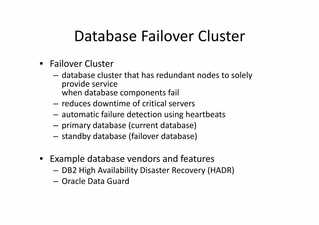
Database Failover ClusterDatabase Failover Cluster
F il Cl t• Failover Cluster– database cluster that has redundant nodes to solely provide service pwhen database components fail
– reduces downtime of critical serverst ti f il d t ti i h tb t– automatic failure detection using heartbeats
– primary database (current database)– standby database (failover database)standby database (failover database)
• Example database vendors and featuresp– DB2 High Availability Disaster Recovery (HADR)– Oracle Data Guard

High Availability Disaster RecoveryHigh Availability Disaster Recovery
• High Availability Disaster Recovery (HADR)• High Availability Disaster Recovery (HADR)– database replication function for high availability
• creation of a standby database via Backup & Restore or Online S lit Mi iSplit Mirroring
• exchange of monitoring messages• use of log file transfer
t titransactions
HADR ships logs to St db d t b
Continuous
Primary database
Logs
Standbydatabase
LogsStandby database transaction
replay
Initialize Standby database using database restore

High Availability Disaster Recovery (2)High Availability Disaster Recovery (2)
R li t d d t d ti• Replicated data and operations– DDL & DML operationsoperations on table spaces and buffer pools– operations on table spaces and buffer pools
– reorganization– metadata for stored procedures and UDFs (but not– metadata for stored procedures and UDFs (but not their implementations)
• Non‐replicated data and operations– database and instance configuration parameters anddatabase and instance configuration parameters andtheir modifications
– LOBs > 1GB

HADR States of the Standby DatabaseHADR States of the Standby Database
l l h• local catch‐up– upon first start– application of local log filesapplication of local log files
• remote catch‐up pending– waiting for connection to primary databaseg p y
• remote catch‐up– application of archived andpp
active log files of the primary database
• peer status– both databases identically updated– transfer and application of the
log file pages to standby databaselog file pages to standby database

HADR Synchronization ModesHADR Synchronization Modes
• HADR S h i ti M d• HADR‐Synchronization Modes– Database configuration parameter: HADR_SYNCMODE– Writing of logs successful, if:
Logs are written to log files on the primary database AND
synchronous (SYNC)– synchronous (SYNC)primary database has received acknowledgement from the standby database that logs are successfully written to log files on the standby database
– near synchronous (NEARSYNC) [Default]near synchronous (NEARSYNC) [Default]primary database has received acknowledgement from the standby database that logs are successfully written main memory on the standby database
– asynchronous (ASYNC)Log records have been delivered to the standby database (no acknowledgement expected)

TAKEOVER CommandTAKEOVER Command• Switching the database roles (takeover) transactions• Switching the database roles (takeover)
– only for the standby database– requirements
• database in peer statusHADR resynchonizes• connection to primary database
available– TAKEOVER HADR ON
DB <dbname> NEW Standby databasePrimary database
Logs
NEW Primary databaseStandby database
Logs
HADR resynchonizesnew Primary and
new Standby databaseContinuous transaction replay
• HADR functionality substitution (failover)– in case of unavailability of the primary database no role‐switching!
only possible for the standby database
Primary database Standby database
– only possible for the standby database– requirements
• database status: peer status or remote catchup pending• primary database must be fully deactivated
→ otherwise two primary databases
transactions
→ otherwise two primary databases→ inconsistencies possible!
– TAKEOVER HADR ON DB <dbname> BY FORCE
Standby database t k
Primary databaseNEW Primary database
Standby database
Logstakes over

Oracle Data GuardOracle Data Guard
• Standby Database Types– Physical standby database
• Application of native redo logs to standby database• Application of native redo logs to standby database
• Fast and efficient synchronization, more simple configuration
• No read access for reporting, no backup of standby database
• since 11g: Active Data Guard option – read access to physical standby database
– Logical standby databaseg y• transformation of redo log toplain SQL and execution of SQL statementsof SQL statements on standby database
• read access for reporting
• Online backup on standby database• Online backup on standby database
• More complex configurationSource: https://mydoag.doag.org/formes/servlet/DocNavi?action=getFile&did=88890&key=

VIRTUALIZATION AND DBMS

Databases: Why Use VMs for databases?
Vi t li ti t h i l l id th b t• Virtualization at hypervisor level provides the best abstraction– Each DBA has their own hardened, isolated, managedEach DBA has their own hardened, isolated, managed sandbox
• Strong Isolation– Security– Performance/ResourcesConfiguration– Configuration
– Fault Isolation• Scalable PerformanceScalable Performance
– Low‐overhead virtual Database performance– Efficiently Stack Databases per‐host
90

DBMS on top of Virtual MachinesDBMS on top of Virtual Machines
• ... yet another application?
• No! Virtualization poses several interesting research questions for database systems– Understanding the performance of database systems on virtual machines
– Configuring and tuning virtual machines running databasesystems
– Taking advantage of virtualization capabilities in the d bdatabase system
91

Performance OverheadPerformance Overhead
native Linux (L), XenoLinux (X), VMware workstation 3.2 (V) and User‐Mode Linux (U).
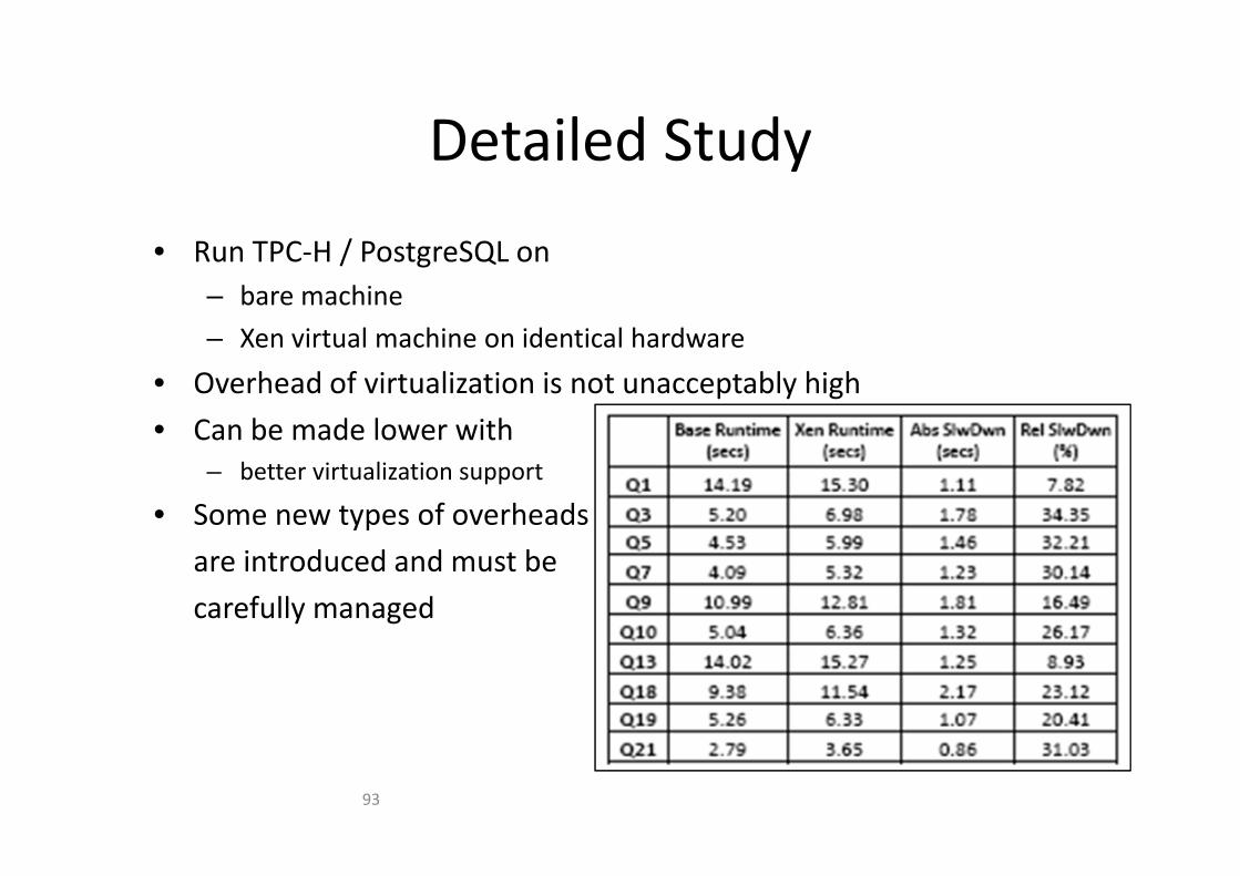
Detailed StudyDetailed Study
/• Run TPC‐H / PostgreSQL on– bare machine
– Xen virtual machine on identical hardware– Xen virtual machine on identical hardware
• Overhead of virtualization is not unacceptably high
• Can be made lower withCan be made lower with– better virtualization support
• Some new types of overheads
are introduced and must be
carefully managed
93

Virtualization and DBMS
TUNING VIRTUAL MACHINES RUNNING DATABASE MANAGEMENT SYSTEMS
Virtualization and DBMS
DATABASE MANAGEMENT SYSTEMS

Resource ProvisioningResource Provisioning• What level of resources to give to each DBMS?
– Configuring VM parameters
• How to tune the DBMS for a given level of resources?Configuring the DBMS parameters– Configuring the DBMS parameters
• Need a model of how resource
allocation affects databaseallocation affects database
performance
• Need optimization or control• Need optimization or control
algorithms to decide on the
optimal resource allocationoptimal resource allocation
– statically
d d i ll– and dynamically95

Dynamic Workloads
5
yWasted resourcesBursty load Bad response time
4
PUs
Peak
3
mbe
r of C
Peak
2Num
Average
0
1 Average
0
Time (every 5 mins)
P i i i f d i kl d i h d!
96
Provisioning for dynamic workloads is hard!96
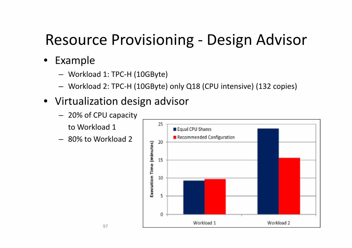
Resource Provisioning Design AdvisorResource Provisioning ‐ Design Advisor• Example
– Workload 1: TPC‐H (10GByte)
– Workload 2: TPC‐H (10GByte) only Q18 (CPU intensive) (132 copies)
• Virtualization design advisor– 20% of CPU capacity
kl dto Workload 1
– 80% to Workload 2
97

Virtualization Design Advisor IVirtualization Design Advisor I
PerformanceGoals
PerformanceModell
Configuration On line RessourceWorkload Ressource PerformanceConfigurationAdvisor
On‐lineMonitoring
RessourceAdjustment
WorkloadDecription
RessourceAllocation
PerformanceData
RessourceAllocation (Dynamic)
98

Virtualization Design Advisor IIVirtualization Design Advisor II• Problem Statement
W : set of workloads processed in the same amount of time– Wi: set of workloads processed in the same amount of time– Ri: resource shares– Di: database instance– minimize
– constraint by degradation limit
– call resources are assigned to Wi
99

Cost Estimation Calibration ICost Estimation – Calibration I
U ti i th t d l• Use query optimizer as the cost model– Calibrate it to reflect virtual machine resource levels– Answer the following question: g q
“If the parameter settings were to be set in a particular way, what would be the cost of the optimal plan for the given workload?"
• Parameters– presecriptive parameters
‐> configuration of DBMS> configuration of DBMS (shared buffers and work mem)
– descriptive parameters‐> execution environment‐> execution environment(cpu tuple cost, random page cost, and effective cache size)
100

Cost Estimation Calibration IICost Estimation – Calibration II
• B i M th d l• Basic Methodology1. Define a calibration query Q and a calibration database D such that
CostDB(Q; Pi;D) is independent of all descriptive parameters in optimizer configuration Pi except for pik.configuration Pi except for pik.
2. Choose a resource allocation Ri, instantiate D, and run Q under that resource allocation, and measure its execution time TQ.
3. Solve Renormalize(CostDB(Q; Pi;D)) = TQ for pik, and associate the resulting l ith th ll ti R H th R li () f tipik value with the resource allocation Ri. Here the Renormalize() function
represents the application of the renormalization factor that was determined for the DBMS.(CostDB * the number of seconds required for a sequential I/O operation)
4. Repeat the two preceding steps for a variety of different resource allocations Ri, associating each with a value of pik.
5. Perform regression analysis on the set of (Ri; pik) value pairs to determine calibration function Cal from resource allocations R to p valuescalibration function Calik from resource allocations Ri to pik values.
101

Calibration StudyCalibration – Study• Problem
N CPU settings– N CPU settings– M memory settings– really need to execute NxM virtual machine settings and
calibrations?
• ObservationObservation– CPU, IO, and memory optimizer parameters are independent of
each other
cpu_tuple_cost cpu_index_tuple_cost cpu_operator_cost102

Configuration EnumerationConfiguration Enumeration
d l h h / h• Greedy Algorithm starting with 1/N share assignment– optimization functions are „fairly smooth and concave“
two workloads competing for CPUtwo workloads competing not for CPU
• Overhead– Calibration (Postgres): 9 minutes
E ti 1 i t
p gp g
– Enumeration: 1 minute
103

Some Experiments ISome Experiments I• Workload Definition based on TPC‐H
– Q18 is one of the most CPU intensive queries– Q18 is one of the most CPU intensive queries– Q21 is one of the least CPU intensive queries– Workload Units
• C: 25x Q18• C: 25x Q18• I: 1x Q21
– Experiment: Sensitivity to workload Resource Needs• W1 = 5C + 5IW1 = 5C + 5I• W2 = kC + (10‐k)I (increase of k ‐> more CPU intensive)
DB2 Postgres
104

Some Experiments IISome Experiments II
kl d• Workload Settings– W3 = 1C
– W4 = kC
• Workload SettingsW5 1C– W5 = 1C
– W6 = kI
105

DB MACHINE VIRTUALIZATION

Multi node Database ArchitecturesMulti node Database Architectures
ll bl l i d b hi• Full‐blown classic database architectures– no shared memory(shared disk / shared nothing)
– Query optimization criteria• high data parallelism• minimal data communication overhead(j i ti !)(joins, aggregations!)
• provide serializable schedule (commit protocol!)
A li ti ‘ ti• Application‘s perspective– SQL prompt

Example: GreenplumExample: Greenplum
• single Postgres Nodes + master servers
• local storageg(PolymorphicData Storage)Data Storage)

Oracle RACOracle RAC• Architecture• Architecture
– Two or more computing nodes with instances – Database nodes connected by high speed private interconnect for
synchronization and communication e g workload balancingsynchronization and communication, e.g. workload balancing– Connection to shared database on disk (SAN)– Cache Coherence with Oracle Cache Fusion
Public network
Node 1 Node 2Highspeed interconnect (IC)
DB Instance 1
DB Instance 2
g p ( )
Localstorage
Localstorage
Storage Network (e.g. SAN)
Shared Disk (database)

Oracle RAC (2)Oracle RAC (2)• Cache Fusion• Cache Fusion
– Cache coherence protocol using high speed private interconnect– "fuses" the in‐memory data cached physically on each computer
into one single global cacheinto one single, global cache– Avoiding synchronization over Shared Disk System I/O
Global Cache
LocalBuffer
LocalBuffer
LocalBuffer
Global Cache
Instance 1
Cache
Instance 3
Cache
ICInstance 2
Cache
Storage Network (e.g. SAN)
Shared Disk (database)

more techniques.. more techniques
• either– ... classical stuff!!!
• or– MapReduce like concepts(already discussed within this lecture)( y )

DB CLOUD VIRTUALIZATION

Virtualization at Multiple Levels IVirtualization at Multiple Levels I
T k li ti / kl d h t i ti i t• Take application/workload characteristics into account
Scenario 1– Scenario 1• different apps run on the same HW‐platform
– Scenario 2Sce a o• multiple instances of the same app (e.g. DBMS) run on the same HW‐platform but for different users
Organize virtual machines based on application– Organize virtual machines based on application characteristics
• Lesson 1– Group jobs with contrary resource requirements (CPU, I/O,…)
• Lesson 2– Group jobs with contrary SLA requirementsGroup jobs with contrary SLA requirements
113

Virtualization at Multiple Levels IIVirtualization at Multiple Levels II
P• Pros– Utilization raised while SLAs are ensured– Classic advisor questions:Classic advisor questions:– Forecast of peaks, low usage times?– Online vs. offline advisor– Placement, migration of jobs, virtual machines– Shut down parts of the cloud when not needed (sustainability)(sustainability)
• Cons– Highly dynamic environment – jobs can arrive anytimeHighly dynamic environment jobs can arrive anytime– Quite a bit of information needed about executed job (which is why we concentrate on DMA cloud)
114

SetupSetupDB DB DB DB DBDB Layer
Instance Instance Instance Instance Instance InstanceInstance Layer
DB Server
Layer
DB Server DB Server DB ServerLayer
VM VM VM VM VMVM Layer VM
HW LayerHW Layer
115

VM Barrier
DB DB DB DB DBDB Layer
User’s PoV
Instance Instance Instance Instance Instance InstanceInstance Layer orProvider’s PoV
DB Server
Layer
gn Adviso
DB Server DB Server DB ServerLayer
Cloud oud Desig
VM VM VM VM VM VMVM Layer DB‐Clo
HW LayerHW Layer
116
Complex Optimization IComplex Optimization I• Design Advisor Input
W kl d S ifi ti d R i t– Workload Specifications and Requirements• I/O, CPU
• Degree of parallelism• Degree of parallelism
• Availability, reliability, durability, scalability, …
– Service Level Agreementsg• Different user classes (standard, premium, … billing based on actual costs, resource usage, service quality)
• Throughput, response time, …
– Hardware Specifications
C i– Constraints• Migration constraints
• Configuration constraints• Configuration constraints
117

Complex Optimization IIComplex Optimization II• Design Advisor Goals
– Maximize Utilization
– Minimize Resource Requirements
– Ensure Service Qualityy
– Minimize reorganization/migration overhead
• Design Advisor ActionsAll ti– Allocation
– VM – HW mapping (contrary VMs share same hardware, VM )
– DBS – VM mapping (parallelism, partitioning)
– DB/Instance – DBS mapping (workload balancing)
• Possible Workload ConsolidationConfiguration– Configuration
– Physical DB design (indexes, bufferpools, …)
– VM configuration
118
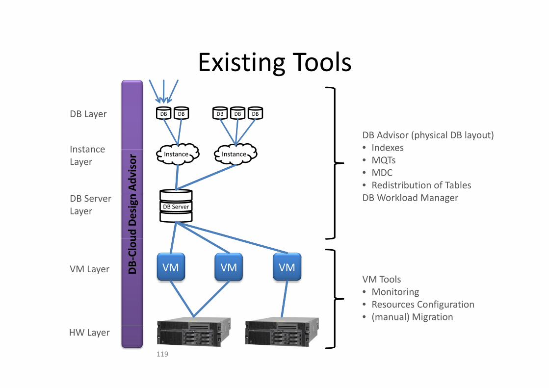
Existing ToolsExisting Tools
Instance
DB DB DB DB DBDB Layer
DB Advisor (physical DB layout)• Indexes
Instance InstanceInstance Layer
Advisor
Indexes• MQTs• MDC• Redistribution of Tables
kl dDB Server
DB Server Layer
ud Design DB Workload Manager
VM VM VMVM Layer DB‐Clou
VM ToolsVM Tools• Monitoring• Resources Configuration• (manual) Migration
HW Layer
119

Layer Interactions ILayer Interactions I
• Static Environment Assumptions– Advisor expects static hardware environment
VM expects static (peak) resource requirements– VM expects static (peak) resource requirements
– Interactions between layers can improve performance/utilization
DB Advisor
VM ConfigurationVM Configuration
120

Layer Interactions IILayer Interactions IIIndex Storage
Possible Improvement
• Experiment– DB2 on Linux
TPC H workload on 1GB database
g
90% 35%25%
20%
– TPC‐H workload on 1GB database
– Ranges for resource grants• Main memory (BP) – 50 MB to 1GB
<1% <3%
5%
10%
15%
Index Expected Performance
• Additional storage (Indexes) – 5% to
30% DB size
Varying advisor output (17 26 indexes)
BP200MB
400MB
600MB
800MB
1GB
Storage
25%
20%
– Varying advisor output (17‐26 indexes)• Different possible improvement
• Different expected Performance after
5%
10%
15%improvement
BP200MB
400MB
600MB
800MB
1GB121

Scenario – Consolidate Workload
DB DB DB DB DBDB Layer
• CPU bound• Strict SLA• …
• I/O bound• Loose SLA• …
Instance Instance Instance Instance Instance InstanceInstance Layer or
DB Server
Layer
gn Adviso
DB Server DB Server DB ServerLayer
oud Desig
VM VM VM VM VM VMVM Layer DB‐Clo
HW LayerHW Layer
122

Workload Consolidation Experiment IWorkload Consolidation Experiment I• Experiment
– DB2 on Linux VM
10 GB TPC H database
Q1 Q2 Q1 Q2
– 10 GB TPC‐H database
– 2 different workloads, t d i lt lexecuted simultaneously
• Long running, I/O intensive queryDBS DBS DBS
• Short running, index accessing query
– Query throughput is measuredVM VM VM
– VM memory configuration varies
123

Workload Consolidation Experiment IIWorkload Consolidation Experiment IIShort Query ‐ Throughput ‐ 10GB TPC‐H
1 VM 2 VMsQ1 Q2 Q1 Q2
350000
360000
370000
380000
per minute
320000
330000
340000
512 MB or 1024 MB 768 MB or 1536 MB 1024 MB or 2048 MB
Que
ries
DBS DBS DBS
memory configuration
Long Query ‐ Throughput ‐ 10GB TPC‐H
VM VM VM
37
38
minute
1 VM 2 VMs
34
35
36
Que
ries per m
124
512 MB or 1024 MB 768 MB or 1536 MB 1024 MB or 2048 MB
memory configuration

CONCLUSION

ConclusionConclusion

Conclusion IConclusion I
h ll l b h dl d• How shall virtualization be handled on– Machine level (VM to HW)
– DBMS level (database to instance to database server)( )
• ... using …– Allocation between layers
C fi i i id l– Configuration inside layers
• … when …– Characteristics of the workloads are known
– Virtual machines are transparent
• … demanding that …d– SLAs are respected
– Each node’s utilization is maximized
– Number of nodes is minimized

Conclusion IIConclusion II
• Virtualization– Powerful mechanisms for improving computing infrastructure
Adopted by a wide range of organizations– Adopted by a wide range of organizations
• Database systems are increasingly being run in virtualizedenvironmentsenvironments– Significantly changes the operating environment
– At the same time can be very useful
Many opportunities for database researchers
129


