Wessex ModuMax mk3 Boilers
Condensing Fully Modulating, Pre-Mix, Gas Fired,
Modular Boilers for Heating and Domestic Hot Water Installations
Installation, Commissioning and Servicing Instructions
Models– 97, 116, 147, 196 & 254
NATURAL GAS I2H
LPG Propane I3P
IMPORTANT NOTE
THESE INSTRUCTIONS MUST BE READ
AND UNDERSTOOD BEFORE INSTALLING,
COMMISSIONING, OPERATING OR
SERVICING EQUIPMENT


HAMWORTHY HEATING LTD
Wessex ModuMax mk3 Boilers
500001308/B
i
NOTE: THESE INSTRUCTIONS MUST BE READ AND UNDERSTOOD BEFORE INSTALLING, COMMISSIONING, OPERATING OR SERVICING EQUIPMENT. THE WESSEX ModuMax BOILER IS INTENDED FOR USE AS A COMMERCIAL APPLIANCE. THIS BOILER IS FOR USE ON GROUP H NATURAL GAS (2
ND FAMILY) I2H and LPG
PROPANE (3RD FAMILY) I3P . PLEASE ENSURE THE RELEVANT INFORMATION WITHIN THIS DOCUMENT FOR EACH SPECIFIC GAS REQUIREMENT IS ADHERED TO PRIOR TO FIRING THE BOILER. COUNTRY OF DESTINATION : UNITED KINGDOM & REPUBLIC OF IRELAND THIS BOILER COMPLIES WITH ALL RELEVANT EUROPEAN DIRECTIVES. PRODUCT IDENTIFICATION No. 86CP58
PUBLICATION NO. 500001308 ISSUE ‘B’ January 2016
Wessex ModuMax mk3 Boilers
Condensing Fully Modulating, Pre-Mix, Gas Fired,
Modular Boilers for Heating and Domestic Hot Water Installations
Installation, Commissioning and Servicing Instructions
Models– 97, 116, 147, 196 & 254
NATURAL GAS I2H
LPG Propane I3P

HAMWORTHY HEATING LTD
Wessex ModuMax mk3 Boilers
500001308/B
ii
CONTENTS Page 1.0 INTRODUCTION ................................................................................................................................ 1 2.0 SUPPLY AND DELIVERY.................................................................................................................. 3 3.0 SIZE AND SPACE REQUIREMENTS ............................................................................................... 6 4.0 SITE LOCATION AND PREPARATION .......................................................................................... 10 4.1 Site Location 4.2 Gas Supply 4.3 Flueing 4.4 Water Supply 4.5 Condensate Connections 4.6 Electrical Supply 5.0 BOILER ASSEMBLY ....................................................................................................................... 15 5.1 Site dis-assembly 5.2 Boiler Assembly 5.3 Water Connections 5.4 Electrical Connections 6.0 PRE-COMMISSIONING ................................................................................................................... 17 6.1 Gas Supply 6.2 Ventilation 6.3 Pipework, Valves and Pump 6.4 Flue 6.5 Electrical 7.0 CHECKS PRIOR TO LIGHTING ...................................................................................................... 18 8.0 INITIAL LIGHTING ........................................................................................................................... 21 8.1 Pre-Lighting-up Checks 8.2 Controls Operation 8.3 Operating Phases 8.4 Ignition Controller Check 8.5 Gas Supply Pressure Check 8.6 Combustion Checks 8.7 User Instructions 9.0 FAULT FINDING .............................................................................................................................. 27 9.1 Temperature Limit Thermostat 9.2 Ignition Controller 9.3 Wiring Diagram 10.0 SERVICING ...................................................................................................................................... 29 10.1 Regular Servicing 10.2 Annual Service 10.3 Four Year Service 11.0 REPLACEMENT OF FAILED COMPONENTS ............................................................................... 31 11.1 Hot Surface Ignitor and Flame Probe Assembly 11.2 Flow/Return Sensor 11.3 Temperature Limiter 11.4 Gas Valve 11.5 Combustion Fan 11.6 Venturi 11.7 Burner 11.8 Ignition Transformer 11.9 Ignition Controller - LMS 11.10 Clip in Modules 11.11 Screen Display 11.12 Low Gas Pressure Switch 11.13 Air Pressure Switch 11.14 Ignition Transformer In-line Fuse
HAMWORTHY HEATING LTD
Wessex ModuMax mk3 Boilers
500001308/B
iii
11.15 Air Inlet Filter 12.0 RECOMMENDED SPARES ............................................................................................................. 35
PICTORIAL AND DIAGRAMATICAL DATA
PAGE
Figure 2.1 Boiler Delivery .......................................................................................................................... 3 Figure 2.2 Boiler Positioning ...................................................................................................................... 3 Figure 2.3 Boiler Packaged Dimensions ................................................................................................... 4 Figure 2.4 Reverse Header Kit as Supplied .............................................................................................. 5 Figure 2.5 Header Kit Packaged Dimensions ............................................................................................ 5 Figure 3.1.1 Dimensions & Clearances ModuMax 97/116 ........................................................................... 6 Figure 3.1.2 Dimensions & Clearances ModuMax 147/196/254 .................................................................. 7 Figure 3.2.1.1 Manifold Dimensions ModuMax 97/194, 116/232 .................................................................... 8 Figure 3.2.1.2 Manifold Dimensions ModuMax 97/291, 116/348 .................................................................... 8 Figure 3.2.2.1 Manifold Dimensions ModuMax 147/294, 196/392, 254/508 ................................................... 9 Figure 3.2.2.2 Manifold Dimensions ModuMax 147/441, 196/588, 254/762 ................................................... 9 Figure 4.2 Gas Connection Point ............................................................................................................ 10 Figure 4.4. Water & Flue Connection Points ............................................................................................ 12 Figure 4.5.1 Condensate Piping Installation ............................................................................................... 13 Figure 4.5.2 Condensate Connections ....................................................................................................... 13 Figure 4.6 Electrical Connections ............................................................................................................ 14 Figure 5.1 Module Fixings ....................................................................................................................... 14 Figure 5.2 Flue Collector Box Pre-Assembly ........................................................................................... 15 Figure 5.2.2 Flue Header Connection ........................................................................................................ 16 Figure 5.3.1 Rear Water Connections ........................................................................................................ 16 Figure 7.1 Boiler Gas System Leak Check Diagram ............................................................................... 18 Figure 7.2.1 Gas Valve Position ................................................................................................................. 19 Figure 7.2.2 Venturi & Gas Valve -196/254 Boiler...................................................................................... 20 Figure 7.2.3 Hot Surface Igniter Resistance Check ................................................................................... 20 Figure 8.1.1 Gas Valve .............................................................................................................................. 21 Figure 8.1.2 General Overview of Low Gas Inlet Pressure Switch ............................................................ 21 Figure 8.2.1 General Overview of Panel Fascia ......................................................................................... 23 Figure 8.2.2 General Overview of Controls ................................................................................................ 23 Figure 8.3.1 Operating Phases ................................................................................................................... 24 Figure 8.6.1 Removal of Sample Point Plug ............................................................................................... 25 Figure 8.6.2 Combustion Analyser Probe Setting ...................................................................................... 25 Figure 8.6.3 Insertion of Analyser Probe .................................................................................................... 25 Figure 8.6.4 High Fire Setting ..................................................................................................................... 26 Figure 8.6.5 Low Fire Setting ...................................................................................................................... 26 Figure 9.3.2 Wiring Diagram ...................................................................................................................... 28 Figure 10.2 Hot Surface Ignitor and Flame Probe Positions ..................................................................... 30 Figure 11.4 Ignition Transformer In-line Fuse ................................................... ....................................... 34 Figure 11.4 Air Inlet Filter ................................................... ...................................................................... 34

HAMWORTHY HEATING LTD
Wessex ModuMax mk3 Boilers
500001308/B
iv
APPENDICES PAGE
APPENDIX A GAS DATA ............................................................................................................................. 36 Figure A General Gas Data ................................................................................................................. 36 APPENDIX B ELECTRICAL CONNECTIONS AND CONTROLS ............................................................... 38 Figure B General Electrical Data ......................................................................................................... 38 Figure B1.2 External Control Wiring for Multiple Module Installations ....................................................... 39 APPENDIX C FLUE DATA ........................................................................................................................... 40 Figure C Flue Data Table ...................................................................................................................... 40 Figure C1.1.1 Equivalent Flue Resistance Data .......................................................................................... 42 Figure C1.1.2 Open Natural Draught (B23/B23p) Flue System .................................................................... 43 APPENDIX D VENTILATION........................................................................................................................ 44 Figure D1 Mechanical Ventilation Flow Rates Chart ............................................................................. 45 APPENDIX E WATER DATA ....................................................................................................................... 46 Figure E1.1 General Water Data ............................................................................................................... 46 Figure E1.1.1 Typical Piping Layout ............................................................................................................. 47 Figure E1.3 Cold Feed and Vent Pipe Sizes Table .................................................................................. 48 Figure E1.3.1 Hydraulic Schematic 1 ............................................................................................................ 50 Figure E1.3.2 Hydraulic Schematic 2 ............................................................................................................ 51 Figure E1.3.3 Hydraulic Schematic 3 ............................................................................................................ 52 Figure E1.3.4 Hydraulic Schematic 4 ............................................................................................................ 53 Figure E1.3.5 Hydraulic Schematic 5 ............................................................................................................ 54

HAMWORTHY HEATING LTD
1 Wessex ModuMax mk3 Boilers
500001308/B
1.0 INTRODUCTION
1.1 This boiler must be installed by a competent person.
1.1.2 All installations MUST conform to the relevant Gas Safety and Building Regulations.
1.1.3 Health & Safety requirements must also be taken into account when installing any equipment.
1.1.4 Failure to comply with the above may lead to prosecution.
1.2 This boiler is intended for use on Group H Natural Gas (2nd Family) I2H or LPG Propane (3rd Family) I3P
1.2.1 The information relating to Natural Gas & Propane firing is to be found in Appendix ‘A’.
1.2.2 Boilers MUST NOT use gas other than that for which they are designed and adjusted.
1.2.3 Regulatory disposal and proper recycling of this product can prevent damage to the environment and health risks.
a) For the disposal of the product and the component parts, the services of an accredited waste disposal company should
be used.
b) For more information on waste disposal/management, contact the local authority responsible for waste management or
the point of sale where the product was purchased.
1.3 The Wessex ModuMax is a gas fired, fully modulating, condensing, fan assisted, open flued central heating / hot water
boiler. Using the latest gas / air ratio control technology it is able to provide clean efficient operation across a large output
range.
1.3.1 The boiler can be supplied in a modular format, a maximum of three vertically stacked modules being arranged into a
single unit sharing a common flue.
1.3.2 Each boiler module utilises a metal fibre, fan assisted, pre-mix burner.
1.3.3 Operation is initiated and controlled by a Navistem boiler management system with a user interface LCD display for
accessing and changing boiler parameters.
1.3.4 Each of the boiler models is designed for direct connection to a flue system. The Technical Data for the various
arrangements is given in Appendix ‘C’. The flue outlets from more than one unit may be connected to a single chimney.
No draught diverter is fitted to the boiler nor is a fixed diverter required in the flue system. However a draught stabiliser may
be required for some installations.
1.3.5 The Wessex ModuMax is floor mounted and is intended for the heating of Commercial and Industrial premises.
It may also be used to supply hot water for these premises via an indirect cylinder.
1.3.6 The Wessex ModuMax has a low water content and water flow rates MUST be maintained at or above the
recommended levels shown in Appendix ’E’.
1.4 If the boiler is to be connected to an un-vented (pressurised) heating system, care must be taken to ensure all extra safety requirements are satisfied and that the relevant interlocks will shut the boiler(s) off should a high or low pressure fault occur. 1.4.1 The pressurisation unit must also incorporate a low level water switch which protects the water pumps and will directly or indirectly shut down the boiler plant should a low water condition occur.
1.4.2 Consideration should also be given to the maximum working pressure of the boiler as given in Appendix ’E’.
Consult Hamworthy Heating Technical Department for help or assistance if in doubt.
1.5 The Wessex ModuMax boiler is not suitable for direct connection to domestic hot water supplies.
1.6 The Wessex ModuMax boiler can be installed with reverse return water flow, (optional HHL pipe kits available) requiring
a primary circuit pump and low loss header, or with individual module shunt pumps or electrical isolating valves (not HHL
supply)
See Appendix ‘E’, figure E1.1 for typical schematic layouts

HAMWORTHY HEATING LTD
2 Wessex ModuMax mk3 Boilers
500001308/B
BOILER VARIATIONS Wessex ModuMax mk3 WM97/97H - Single 97 kW unit Wessex ModuMax mk3 WM97/194V - Single 194 kW unit.( created by stacking 2 – 97 kW modules vertically ). Wessex ModuMax mk3 WM97/291V - Single 291 kW unit.( created by stacking 3 – 97 kW modules vertically ). Wessex ModuMax mk3 WM116/116H - Single 116 kW unit. Wessex ModuMax mk3 WM116/232V - Single 232 kW unit Wessex ModuMax mk3 WM116/348V - Single 348 kW unit Wessex ModuMax mk3 WM147/147H - Single 147 kW unit. Wessex ModuMax mk3 WM147/294V - Single 294 kW unit. Wessex ModuMax mk3 WM147/441V - Single 441 kW unit. Wessex ModuMax mk3 WM196/196H - Single 196 kW unit. Wessex ModuMax mk3 WM196/392V - Single 392 kW unit Wessex ModuMax mk3 WM196/588V - Single 588 kW unit. Wessex ModuMax mk3 WM254/254H - Single 254 kW unit. Wessex ModuMax mk3 WM254/508V - Single 508 kW unit. Wessex ModuMax mk3 WM254/762V - Single 762 kW unit . 1.7 The fully assembled unit is supplied covered with a protective sleeve. The flue assemblies for the stacked models are supplied in a separate pack. 1.8 Each Wessex ModuMax module can be controlled by a 0-10V analogue control input capability which is available via the Navistem boiler control. 1.9 Options 1.9.1 Optional reverse return header kits are available for models: 97/194, 97/291, 116/232, 116/348, 147/294, 147/441, 196/392, 196/588, 254/508 & 254/762 These kits are free-standing allowing installation to the system prior to installing the boiler and can incorporate all necessary valves, inter connecting pipework, and flexible flow and return connections. Refer to individual kit instructions for details. 1.9.2 Controls peripherals The Navistem boiler management system has the potential to accept the following control options: 1.9.2.1 Clip in Fault Alarm & Run Signal AGU2.550A109 Optional kit for a Run/Fault signal. (available as a kit from Hamworthy Heating Ltd) Kit Part No. 563605666 1.9.2.2 Clip in LPB Bus comms OCI345 LPB sequencing of the cascade controlled by Merley / RVS (available as a kit from Hamworthy Heating Ltd) Kit Part No. 563605667 1.9.2.3 Additional kits available from Hamworthy Heating : Merley Sequence Controller - Loose Kit 563605671 or Fully Assembled 563605672 Additional Heating Circuit Kit - 563605673 Domestic Hot Water (DHW) Kit - 563605674 Outside Air Temperature Sensor - 533901457 Room Sensor QAA55 - 533901589 Room Sensor QAA75 - 533901587 1 Zone Heating Circuit Kit - 563605668 2 Zone Heating Circuit Kit - 563605669 3 Zone Heating Circuit Kit - 563605670 1.9.2.4 Regulatory disposal and managed recycling of this product can prevent damage to the environment and health risks. a) For the disposal of the product and the component parts, the services of an accredited waste disposal compa-ny should be used. b) For more information on waste disposal/management, contact the Local Authority responsible for waste man-agement or the point of sales where the product was purchased.

HAMWORTHY HEATING LTD
3 Wessex ModuMax mk3 Boilers
500001308/B
2.0 SUPPLY AND DELIVERY
Your boiler is despatched to site as a pre-assembled and tested unit. Each boiler is delivered by a tail lift
vehicle and lowered to ground level. It is the installers responsibility to convey the boiler to the plantroom.
The base of each boiler is specially designed to accept a standard pallet truck. This allows the boiler to be
manoeuvred into position without any pallets to remove. Additionally the boiler is designed to pass through a
standard doorway where access is restricted.
NOTE: The boiler is packaged with cardboard corner protection and shrunk wrapped for basic protection during handling. However, when manoeuvring the boiler care must be taken to avoid damage to the casing. The boiler must be kept upright during handling. Care must be exercised to avoid toppling the boiler as this will result in damage.
Each 2 and 3 high stacked Wessex ModuMax model is
supplied with a flue collector manifold. This is separately
packaged in a dedicated cardboard box. Single Wessex
ModuMax boilers do not have an additional flue collector
manifold. NOTE: Care must be taken as impacts will cause damage to the flue collector manifold.
Figure 2.1 - Boiler Delivery
Figure 2.2 - Boiler Positioning

HAMWORTHY HEATING LTD
4 Wessex ModuMax mk3 Boilers
500001308/B
Model Depth Width Height Weight
Wessex ModuMax 97/97 & 116/116 1200mm 780mm 900mm 180kg
Wessex ModuMax 97/194 & 116/232 1200mm 780mm 1420mm 355kg
Wessex ModuMax 97/291 & 116/348 1200mm 780mm 1980mm 540kg
Flue Manifold Kit 97 & 116 260 mm 260 mm 600mm 5kg
Wessex ModuMax 97/194 Wessex ModuMax 116/232
x2 10kg
Wessex ModuMax 97/291 Wessex ModuMax 116/348
x3 15kg
Wessex ModuMax 147/147 1200mm 780mm 900mm 226kg
Wessex ModuMax 147/294 1200mm 780mm 1420mm 452kg
Wessex ModuMax 147/441 1200mm 780mm 1980mm 678kg
Wessex ModuMax 196/196 1200mm 780mm 900mm 226kg
Wessex ModuMax 196/392 1200mm 780mm 1420mm 452kg
Wessex ModuMax 196/588 1200mm 780mm 1980mm 678kg
Wessex ModuMax 254/254 1200mm 780mm 900mm 226kg
Wessex ModuMax 254/508 1200mm 780mm 1420mm 452kg
Wessex ModuMax 254/762 1200mm 780mm 1980mm 678kg
Flue Manifold Kit 147/196/254 350mm 350mm 600mm 6.5kg
Wessex ModuMax 147/294 Wessex ModuMax 196/392 Wessex ModuMax 254/508
x2 13kg
Wessex ModuMax 147/441 Wessex ModuMax 196/588 Wessex ModuMax 254/762
x3 19kg
Delivery Verification
When taking delivery please ensure that you have received the correct number of boilers and flue collector
manifold to fulfil your order. If any item is missing please contact our after sales service team. Please provide
details of your order number and contract number as well as a detailed description of the missing item.
Figure 2.3 - Boiler Packaged Dimensions

HAMWORTHY HEATING LTD
5 Wessex ModuMax mk3 Boilers
500001308/B
Reverse Return Header Sets
Model Depth Width Height Weight
Wessex ModuMax 97/196, 116/232.
1200mm 800mm 1490mm 116Kg
Wessex ModuMax 97/291, 116/348.
1200mm 800mm 2040mm 160kg
Wessex ModuMax 147/294, 196/392, 254/508
1200mm 800mm 1520mm 192kg
Wessex ModuMax 147/441 196/588, 254/762.
1200mm 800mm 2060mm 233kg
Figure 2.5 - Header Kit Packaged Dimensions
Figure 2.4 - Reverse Header Kit
Where reverse return header sets are used these are packaged separately from the boilers. The packaging
for each header set is defined in the table below. Ancillary items such as isolation valves and flexible boiler
connectors are packaged in a cardboard box on the same pallet. The whole package is shrink wrapped for security
and basic protection.

HAMWORTHY HEATING LTD
6 Wessex ModuMax mk3 Boilers
500001308/B
3.0 SIZE AND SPACE REQUIREMENTS
3.1 The Wessex ModuMax Series boiler range has been designed to utilise minimum floor space by stacking boiler
modules, therefore it is important the plantroom has sufficient ceiling height to allow for installation and connection to the
flue system.
Also important is allowance for sufficient access at sides and rear of boiler for flue and pipework connections. See Figure
3.1.1 below.
Figure 3.1.1 - Dimensions and Clearances 97 & 116
400
400 1250750 CRS
390RELIEF
415 CONDENSE
120 FLUE
620GAS
680
568
717.
1
102
815836.3
583.2
FLUE
204.9 CONDENSE
1258
1798
.92084
.31
1543
.41
54.5GAS
44RELIEF
291.66 FLUE CONDENSATE
350.54
723.1
COND
ENSE
O100 FLUE SOCKET
477 RETURN
303FLOW
350.54
FLUE
CON
DENS
ATE
1264
COND
ENSE
586.89
FLOW
610.2
RELIEF
666.2
GAS
91FLOW & RETURN
G 1 1/2" MALE - RETURN
G 1 1/2" MALE - FLOW
O32 CONDENSE DRAIN(1 PER MODULE)
285.51
RETU
RN
182.2
COND
ENSE
R3/4" RELIEF VALVE(1 PER MODULE)NOT SUPPLIED
600
Rp 1" GAS SUPPLY(1 PER MODULE)
702.5 SINGLE1454 DOUBLE
2204 TRIPLE CASCADE WIDTH
750 CRS
Minimum clearances
3 Modules High
2 Modules High
1 Modules High
Minimum boiler to boiler stack spacing
180CL FLUE120CL FLUEO180 FLUE
826.41
RETU
RN
1127
.79
FLOW
1151
.1RE
LIEF
1207
.1GA
S
1124
.1FL
UE
MOD
ULE
SPAC
ING
540.9
540.9
1367
.31
RETU
RN
1668
.69
FLOW
1692
RELIEF
1748
GAS
1665
FLUE

HAMWORTHY HEATING LTD
7 Wessex ModuMax mk3 Boilers
500001308/B
Figure 3.1.2 - Dimensions and Clearances 147/196/254
400
400 1250750 CRS
390RELIEF
415 CONDENSE
120 FLUE
620GAS
680
568
717
102
8151082
583
FLUE
205 CONDENSE
1258
1799
2084
1543
54GAS
44RELIEF
342 FLUE CONDENSATE
278
723
COND
ENSE
O150 FLUE SOCKET
477 RETURN
303FLOW
1264
COND
ENSE
587
FLOW
610
RELIEF
666
GAS
92FLOW & RETURN
G 2 1/2" MALE - RETURN
G 2 1/2" MALE - FLOW
O32 CONDENSE DRAIN(1 PER MODULE)
286
RETU
RN
182
COND
ENSE
R3/4" RELIEF VALVE(1 PER MODULE)NOT SUPPLIED
600
Rp 1 1/4" GAS SUPPLY(1 PER MODULE)
278
FLUE
CON
DENS
ATE
750 CRS
704 SINGLE1454 DOUBLE
2204 TRIPLE CASCADE WIDTH
Minimum clearances
3 Modules High
2 Modules High
1 Modules High
Minimum boiler to boiler stack spacing
230CL FLUE 135CL FLUEO250 FLUE
MOD
ULE
SPAC
ING
541
541
1207
GAS
1151
RELIEF
1128
FLOW
826
RETU
RN
1124
FLUE
1665
FLUE
1367
RETU
RN
1669
FLOW
1692
RELIEF
1748
GAS

HAMWORTHY HEATING LTD
8 Wessex ModuMax mk3 Boilers
500001308/B
3.2.1 The Hamworthy Heating Ltd water manifold kit is designed to provide a compact solution for connecting the boilers to
the gas supply and flow and return water connections. There are two kits specific to individual models. (Refer to the
Installer’s Guide 500005117 for specific details on the manifold kit. suitable for 97/116 models)
*Optional accessory kits to control shunt pumps and valves can be found on page 2 of this manual*
Safety Valve: When using this kit it is important that each boiler module is fitted with an individual safety valve using the
connection provided on the back of each boiler. This item is not supplied with the boiler.
Figure 3.2.1.2 – Manifold Dimensions for ModuMax 97/291 & 116/348
Figure 3.2.1.1 – Manifold Dimensions for ModuMax 97/194 & 116/232
747
747
28,5
747
747
28,5
HAMWORTHY HEATING LTD
9 Wessex ModuMax mk3 Boilers
500001308/B
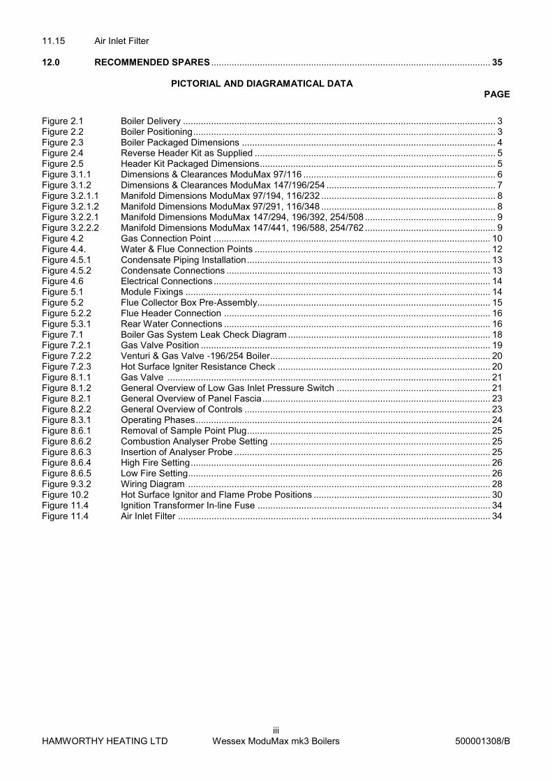
Figure 3.2.2.2 – Manifold Dimensions for ModuMax 147/441, 196/588, 254/762
Figure 3.2.2.1 – Manifold Dimensions for ModuMax 147/294, 196/392, 254/508
3.2.2 The Hamworthy Heating Ltd water manifold kit is designed to provide a compact solution for connecting the boilers to
the gas supply and flow and return water connections. There are two kits specific to individual models. (Refer to the
Installer’s Guide 500005119 for specific details on the manifold kit. suitable for 147/196/254 models)
*Optional accessory kits to control shunt pumps and valves can be found on page 2 of this manual*
Safety Valve: When using this kit it is important that each boiler module is fitted with an individual safety valve using the
connection provided on the back of each boiler. This item is not supplied with the boiler.
570
747 R EF.
10
57
18
0
541
58
65
41
54
128
0.5
5N
OM
.
690
Finished Floor Level
R2" GAS PIPE IS SUPPL IEDLOOSE A ND C AN BE FITTEDTO B OILE R WITH G ASCON NEC TION AT E ITHE RTOP OR BOTTOM
150 NB PN16FLANGES
747 R EF.
15
98
18
0
54
154
1
541
54
158
6
54
1541
28
0.5
5N
OM
.
570
690
150 NB PN 16FLANGES
R2" G AS PIPE IS SUPPLIEDLOOSE AND CAN BE FITTE DTO BOILER WITH GASCONN ECTION AT EITHERTOP O R BOTTOM
Finished Floor Level
HAMWORTHY HEATING LTD
10 Wessex ModuMax mk3 Boilers
500001308/B
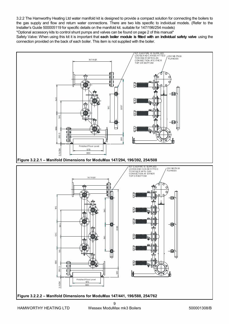
Figure 4.2 – Gas Connection Point
Gas Connection with inlet pressure test point. Rp 1” (97 & 116) & Rp 1-1/4” (147/196/254)
4 off lifting holes - Ø51mm
4.0 SITE LOCATION AND PREPARATION
4.1 Site Location.
The floor or plinth for the boilers and water manifold kit must be both flat and level to ensure correct alignment of fittings and connections.
The floor or plinth must be sufficiently strong to support the weight of both the boilers and manifold kit where used.
In the event that the boiler cannot be moved on a pallet truck, the boiler base is provided with 4 x Ø51 holes as lifting points. These will allow the use of Ø50 lifting poles and suitable lifting straps to lift the boiler into position.
DO NOT LIFT THE BOILER BY THE CASING PANELS!
The floor or plinth must be fireproof in accordance with BS 6644.
The plantroom must have sufficient space for installation of boilers, manifold kits, pipework, pumps controls, flues ventilation, access and servicing and other items of plant.
4.2 Gas Supply.
Gas supply pipes must be in accordance with BS 6891 or IGE/UP/2
Gas supply connections to the boiler must not be smaller than the connection on the boiler - Rp1” (97 & 116) & Rp11/4” (147/196/254)
Gas installation must be soundness tested to BS 6891 or IGE/UP/1 & IGE/UP/1A.
Gas installation must be purged to BS 6891 or IGE/UP/1 & IGE/UP/1A.
Boiler inlet gas pressure; nominal 20mbar (minimum 17.5mbar) for Natural Gas or nominal 37 - 50mbar (minimum 30mbar) for LPG dynamic at the connection to the boiler.
Boiler house gas isolation valve must be clearly identified and installed close to the entrance / exit.

HAMWORTHY HEATING LTD
11 Wessex ModuMax mk3 Boilers
500001308/B
4.3 Flueing
Flue termination, routing and construction must comply with the requirements of the Clean Air Act 1956, BS 6644 and IGE/UP/10.
The Wessex ModuMax 97 , 116 ,147, 196 & 254 boilers are intended for connection to a traditional chimney system- refer to Appendix C for installation details.
Wessex ModuMax 2 and 3 high stacked models must use the headers provided with the boiler prior to any connection to the flue system. A condense trap (32mm dia.) is supplied with the flue header.
Any flue must be self supporting and separable from the boiler for servicing requirements.
The maximum number of modules firing into a common chimney is 9. For larger installations refer to HHL Technical
Due to the low flue gas temperature, 50°C (condensing) - 80 °C (non-condensing), condensation will occur in the flue, flue materials must be non-corrosive and utilise fully sealing joints.
Flue construction is recommended of a twin wall, insulated type to maintain buoyancy within the flue.
Adequate facilities must be provided for draining the flue condensation.
Horizontal flue runs must be kept as short as possible and be inclined at minimum 2° towards the terminal.
The flue system must be designed acknowledging that there is a positive pressure generated by the boiler combustion fan. Refer to Appendix C.
The flue system must be designed to limit the max. suction (cold) to 30Pa negative, measured at the connection to the boiler. If the suction is greater than 30Pa, refer to HHL technical.
This condition must then be checked hot and with all boilers firing, the max. pressure at the connection to the boiler should be 150Pa positive. In the event that the flue system when hot does generate a suction, the max. suction is 100Pa. Any stabiliser fitted must be in or close to the vertical chimney.
Fan dilution - the design must provide for the use of balancing and trim dampers,
and their location and operation must be such that the constraints detailed above
can be met. Care must be taken to ensure that the fan performance is matched to
deliver the appropriate dilution, whilst ensuring that excessive suction is not
applied to the boilers. If in doubt, refer to HHL Technical.
Fan assist - the use of fan assist is not recommended as the boilers have sufficient
fan performance to drive the system. If in doubt, refer to HHL Technical.
HAMWORTHY HEATING LTD
12 Wessex ModuMax mk3 Boilers
500001308/B
4.4 Water Supply
Feed and Expansion tanks to comply with static height requirements of HSE document INDG436.
Cold feed and open vent pipes to comply with requirements of BS 6644.
Pressurised system to comply with BS 7074.
It is recommended that the system pipework is flushed twice before fitting the boiler and using a water treatment.
It is recommended that the heating system water is treated
In hard water areas (>180mg CaCO3/litre) precautions such as water treatment are strongly recommended to prevent the build up of sludge and scale and also to control the system water pH to between 7.0 & 8.0.
Leaks in the system pipework should be fixed to prevent dilution of water treatment. To monitor the volume of make-up water entering the system, a water meter must be fitted and readings recorded in a log book to be retained on site. Do not top up with more than 5% of the installation's water content in any one year.
Maximum working water pressure is 10bar (1000 kPa).
For minimum water pressure see Appendix ‘E’ - Water Data
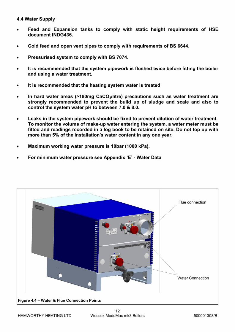
Water Connection
Figure 4.4 – Water & Flue Connection Points
Flue connection

HAMWORTHY HEATING LTD
13 Wessex ModuMax mk3 Boilers
500001308/B
4.5 Condensate Connections Provision must be made for removal of condensate from the boiler and flue system. Condense is mildly acidic, typically pH3 - pH5. Condense pipework must be non-corrosive and not copper. Hamworthy recommend
32mm dia. Plastic waste pipe. Typical volume of condensate produced is 15l/h per 100kW
Condense may be discharged to a standard drain subject to National or Local
regulations. Location of condense pipework should prevent freezing within tundish’s, traps and
pipework. The connection to the boiler condense drain accepts a straight push-fit coupling for
32mm i.d. plastic waste pipe.
Boiler Condensate Connection (32mm o/d)
Figure 4.5.2 – Boiler Condensate Connection
Open Tundish
Condense ‘U’ Trap
Minimum Fall 30mm/m(1 in 30)
Boiler Flue
Metal sheath to protectplastic pipe
The volume of condensateis related to the system water
temperature and firing rateof boiler.
Figure 4.5.1 - Boiler Condensate Piping Installation
HAMWORTHY HEATING LTD
14 Wessex ModuMax mk3 Boilers
500001308/B
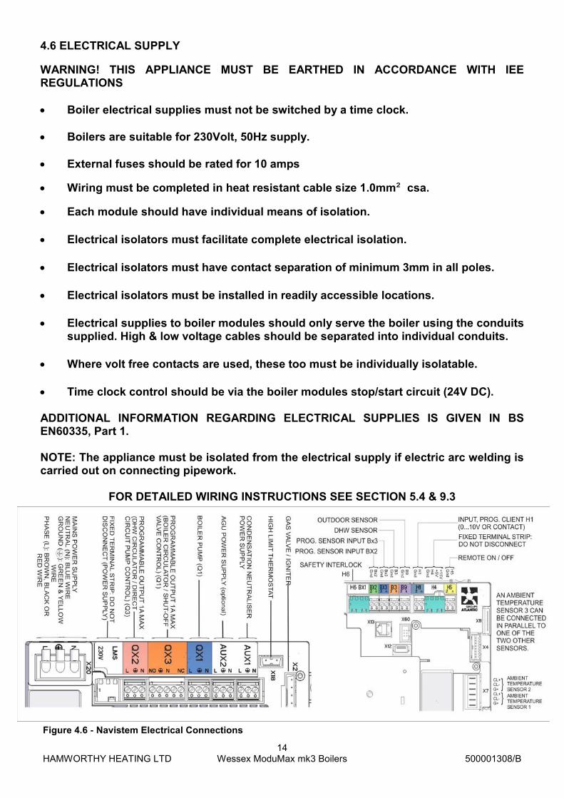
4.6 ELECTRICAL SUPPLY
WARNING! THIS APPLIANCE MUST BE EARTHED IN ACCORDANCE WITH IEE REGULATIONS
Boiler electrical supplies must not be switched by a time clock.
Boilers are suitable for 230Volt, 50Hz supply.
External fuses should be rated for 10 amps
Wiring must be completed in heat resistant cable size 1.0mm² csa.
Each module should have individual means of isolation. Electrical isolators must facilitate complete electrical isolation.
Electrical isolators must have contact separation of minimum 3mm in all poles.
Electrical isolators must be installed in readily accessible locations. Electrical supplies to boiler modules should only serve the boiler using the conduits
supplied. High & low voltage cables should be separated into individual conduits. Where volt free contacts are used, these too must be individually isolatable. Time clock control should be via the boiler modules stop/start circuit (24V DC). ADDITIONAL INFORMATION REGARDING ELECTRICAL SUPPLIES IS GIVEN IN BS EN60335, Part 1. NOTE: The appliance must be isolated from the electrical supply if electric arc welding is carried out on connecting pipework.
FOR DETAILED WIRING INSTRUCTIONS SEE SECTION 5.4 & 9.3
Figure 4.6 - Navistem Electrical Connections

HAMWORTHY HEATING LTD
15 Wessex ModuMax mk3 Boilers
500001308/B
5.0 BOILER ASSEMBLY General Boilers are despatched to site as fully assembled units. The flue collector box (stacked models only) and pipework manifold set (where applicable) are the only items that will need assembling on site. Where access is a problem, stacked models can be broken down into individual modules and then re-assembled in the appropriate location in the plant room - see section 5.1 During dismantling and assembly it is important to take care to prevent damage to the boiler casing. Boiler positioning must allow the minimum clearances detailed in Section 3.0 to facilitate access for flue and pipework connections as well as maintenance.
5.2 Boiler Assembly 5.2.1 With the boiler in its desired location, loosely engage the flue collector ducts into each other and position such that the spigots will fit into the respective flue sockets at the rear of the boiler. In assembling the flue ducts, it is advisable to lubricate the seal located in the socket fittings to enable easy movement and adjustment. 5.2.2 Fit and secure the bottom closing plate to the base of the duct assembly. Do not fit the flue collector at this stage as it may restrict access to the other connections. Note: Should modules be arranged in banks of 2 or 3 high, adjacent to each other, it is advisable to fit the water and flue connections to each individual bank prior to fitting the connections to the adjacent bank(s).
Figure 5.2 - Flue Collector Box Assembly
Modular Tee
Closing plate with condense discharge
5.1 - Site dis-assembly The individual modules are secured by 4 x M8 bolts securing the boiler frames together - see figures 5.1 5.1.1 To access the M8 bolts, remove the M8 socket head screw securing the top module front cover and carefully lift the cover up, disengaging the locating bracket while lifting off the cover. Carefully place the cover aside for re-assembly. 5.1.2 Remove the pozi screw securing the top panel to the boiler frame and remove the top panel, placing aside for re-assembly. 5.1.3 Carefully disengage both casing side panels from the M6 ballstuds. 5.1.4 Access the 4 - M8 bolts (2 per side) and withdraw the bolts from the frame. The top module is now free to carefully lift off the lower module. Warning - the top module is heavy and will require the appropriate use of lifting methods & equipment (155kg 97-116 models & 200kg 147-254 models). 5.1.5 4 x M8 lifting eyes must be placed in the M8 holes in the top of the boiler frame to provide lifting points. 5.1.6 With the base module in the appropriate position, carefully rebuild the stacked modules, securing with the M8 bolts and refit the side panels, top cover and front cover.
M8 Bolt - 2 per side
Top panel fixing screw
Figure 5.1 Module fixings

HAMWORTHY HEATING LTD
16 Wessex ModuMax mk3 Boilers
500001308/B
Prior to fitting the flue collector assembly, check all water and gas connections for soundness. Lubricate the seals on the boiler flue spigot to ena-ble easy movement and adjustment. Adjust and fit the assembled flue collector box to the boiler flue spigots and fit the condense drain discharge pipe to the base of the flue using the fitting supplied.
Figure 5.2.2 - Flue Header Connection
32mm condense trap fitted for connection to drain
5.3 Water Connections:
The following connections are provided on each boiler module;
Figure 5.3.1 - Rear Water Connections
Flow G1½” Male thread (97 & 116) Flow G2½” Male thread (147/196/254). Indicated by a red dot on boiler.
Safety valve R¾ Male thread. Adjacent to flow connection. Capped when delivered.
Condense 32mm dia. Male plain. Offset and below return connection.
Gas R1” Male (97 & 116) Gas R11/4” Male (147/196/254)
Return G1½” Male thread (97 & 116) Return G2½” Male thread (147/196/254). Indicated by a blue dot on boiler.

HAMWORTHY HEATING LTD
17 Wessex ModuMax mk3 Boilers
500001308/B
Connecting flue pipework must be self-supporting to avoid stress on the boiler connections. Local unions are recommended in the flue pipework to facilitate future servicing requirements. Open Vented Systems Boilers must not be capable of isolation from the vent pipe. Valves between boiler and vent pipe to be three way type such that when boiler is isolated from vent pipe it is open to atmosphere. Safety valves should be mounted on the boiler using the connection provided. Sealed Systems Boilers must not be capable of isolation from the safety valve. Valves between boiler and safety valve to be three way type such that when boiler is isolated from the safety valve it is open to atmosphere. Hamworthy Heating Ltd recommend using the safety valve connection provided on the boiler. Where using Hamworthy Heating Ltd pipework kits, assembly of these is detailed in Operation and Maintenance manual 500005117 (97 & 116), 500005119 (147/196/254) supplied with kit. 5.4 Electrical Connections: The following electrical connections are provided on each module.
Supply: Live, Neutral and Earth. See Section 4.5 for details.
Optional Boiler Fault Alarm & Normal Run Signal Output (optional AGU clip-in kit)
0-10v Analogue Control Signal Input
Remote on/off Control Input
Boiler Pump Output, DHW pump output, motorised valve output
Safety Interlock Circuit Input
Optional LPB Bus for use with Merley cascade control (optional OCI clip-in kit) & Master/Slave sequencing 6.0 PRE-COMMISSIONING The following pre-commissioning check must be carried out before the boiler is commissioned. 6.1 Gas Supply. Ensure that gas installation pipework and meter has been soundness tested and purged to IGE/UP/1 or IGE/UP/1A as appropriate. Test and purge certificates should be available for viewing. 6.2 Ventilation Ensure that ventilation and air supply to plant room is correct. Air supply slots in casing panels are clear and open. 6.3 Pipework, Valves and Pump Ensure that;
Pipework and valve arrangement is installed to Hamworthy Heating recommendations.
Circulating system is full of water, vented and pressurised appropriately and the water quality checked.
Circulation pump is fitted, working and interlocked where required.
Pipework connections to boiler are fitted correctly.
All necessary isolation valves are open.
Safety valve is correctly sized and located.
Condense connections on boiler and flue are connected and piped to drain.
Heat load is available.
HAMWORTHY HEATING LTD
18 Wessex ModuMax mk3 Boilers
500001308/B
7.0 Checks Prior to Lighting
IMPORTANT: BEFORE PROCEEDING ENSURE THAT THE PRE-COMMISSIONING CHECKS ON PAGE 14 HAVE BEEN CARRIED OUT AND THE RESULTS SATISFACTORY.
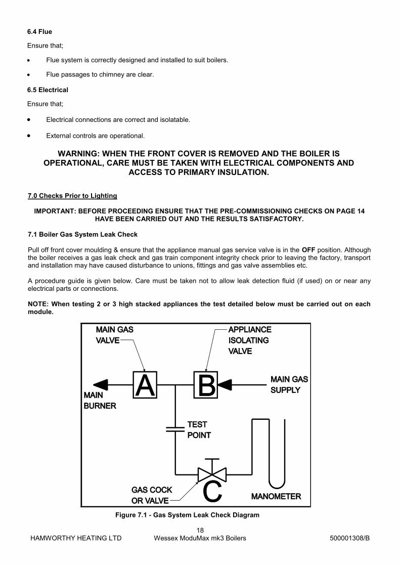
7.1 Boiler Gas System Leak Check Pull off front cover moulding & ensure that the appliance manual gas service valve is in the OFF position. Although the boiler receives a gas leak check and gas train component integrity check prior to leaving the factory, transport and installation may have caused disturbance to unions, fittings and gas valve assemblies etc. A procedure guide is given below. Care must be taken not to allow leak detection fluid (if used) on or near any electrical parts or connections. NOTE: When testing 2 or 3 high stacked appliances the test detailed below must be carried out on each module.
Figure 7.1 - Gas System Leak Check Diagram
6.4 Flue
Ensure that;
Flue system is correctly designed and installed to suit boilers.
Flue passages to chimney are clear. 6.5 Electrical
Ensure that;
Electrical connections are correct and isolatable.
External controls are operational.
WARNING: WHEN THE FRONT COVER IS REMOVED AND THE BOILER IS OPERATIONAL, CARE MUST BE TAKEN WITH ELECTRICAL COMPONENTS AND
ACCESS TO PRIMARY INSULATION.

HAMWORTHY HEATING LTD
19 Wessex ModuMax mk3 Boilers
500001308/B
Note:- Main Gas Supply Pressures are as follows; Natural Gas - 20mbar, LPG - 37mbar. TO CHECK B 1) Turn off the electrical power and gas to the appliance. 2) Connect the manometer assembly to test point (Fitted on the inlet to the gas valve). 3) With A and B closed open C and monitor manometer over a 2 minute period, a rise indicates a leak on valve B. TO CHECK A 1) Open C. 2) Open B to produce the mains gas supply pressure between A and B. 3) Close B. 4) System may be considered sound if over a period of 2 minutes any drop in pressure is less than 0.5 mbar Note:- Allow a manometer stabilisation period of approximately 1 minute before each 2 minute check period. Following soundness tests close valve B and remove manometer connections and tighten test points. 7.2 Refer to Appendix A, Gas Data Tables, for maximum inlet pressure for normal operation. The Following checks must be made prior to lighting the boiler;
Figure 7.2.1 - Gas Isolating Valve (97 & 116 shown)
1. Ensure that the gas supply is connected, but the boiler module gas service (isolating) valve(s) are closed, any unions or fittings are correctly tightened and test points are closed. 2. Ensure the electrical mains supply is correctly connected but the boiler module isolator(s) are switched off. Check all wiring loom connections such as fan or gas valve are correct and secure. Remove the clip, limit stat bulb and tension spring from the pocket in the front of the heat exchanger, and carefully apply a heat source to the bulb. Note - take care not to damage the tension spring in removal and replacement! Check the continuity with a meter. If satisfactory, refit the bulb and tension spring in the pocket and secure with the clip. Ensure that all thermostat bulbs are fully inserted into their pockets. The flow and return sensor bulbs are located at the rear of the boiler in the flow and return pipes.
3. Check setting of both temperature limiter and control thermostat. The temperature limiter is factory set at 95°C. The control thermostat is set using the rotary dial on the fascia as detailed in the separate User Instructions, HHL part no. 500001309. 4. The flame ionisation signal generated whilst the boiler is firing, can be viewed directly from the display by accessing information level. The value is set to read dc μA. Refer to the separate Navistem manual, HHL part no. 500001310. 5. To ensure correct ignition of the boiler it is recommended to check the resistance of the hot surface igniter. This should be checked cold, using a suitable ohmmeter, by disconnecting the igniter from the control panel cable and measuring the resistance across the pins of the 2 way connector. The reading should be between 70 & 200 ohms refer to figure 7.2.3 6. Before ignition of the boiler it must be ensured that all parts of the appliance are clean and free from debris. Special attention should be paid to ensuring that the inlet to the venturi via the air filter is clean and unobstructed. 7. Ensure the heating system circulation / shunt pump is operational and that the pipework is free of air. 8. The flame ionisation signal generated whilst the boiler is firing, can be viewed directly from the display screen. The value is set to read dc μA.
HAMWORTHY HEATING LTD
20 Wessex ModuMax mk3 Boilers
500001308/B
Flame Signal Assessment
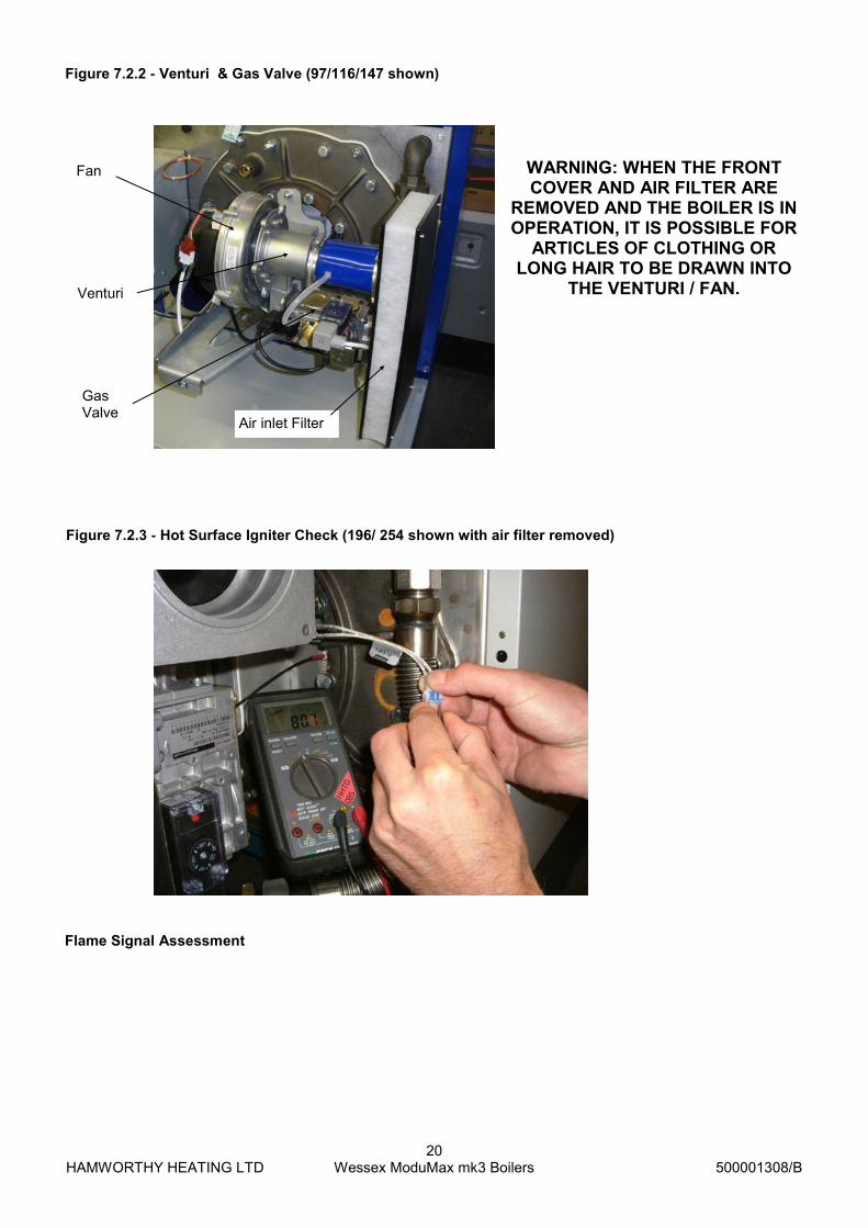
Figure 7.2.3 - Hot Surface Igniter Check (196/ 254 shown with air filter removed)
Figure 7.2.2 - Venturi & Gas Valve (97/116/147 shown)
WARNING: WHEN THE FRONT COVER AND AIR FILTER ARE
REMOVED AND THE BOILER IS IN OPERATION, IT IS POSSIBLE FOR
ARTICLES OF CLOTHING OR LONG HAIR TO BE DRAWN INTO
THE VENTURI / FAN. Venturi
Air inlet Filter
Gas Valve
Fan

HAMWORTHY HEATING LTD
21 Wessex ModuMax mk3 Boilers
500001308/B
8.0 INITIAL LIGHTING Only competent persons registered for working on non-domestic gas appliances should attempt the following operations. Before attempting to commission any boiler, ensure that personnel involved are aware of what action is about to be taken. 8.1 Carry out the following procedure to fire up the boiler:
1. Ensure the boiler module gas service (isolating) valve is closed (Figure 8.1.1)
Figure 8.1.1 - Gas Isolating Valve
2. Check and adjust if necessary the low gas inlet pressure switch located on the side of the boiler gas valve (fig. 8.1.2). Setting should be 97, 116 &147 to 7 mbar 196 and 254 to 7.5 mbar 3. Switch on the electrical supply, and initiate the start up sequence. Refer to separate Navistem manual, HHL part no. 500001310. 4. As the gas valve is closed, the low gas pressure switch will prevent the boiler from firing and the error code ‘E132’ will be displayed on the screen. Refer to separate Navistem manual, HHL part no. 500001310. 5. If the above procedure occurs correctly, open the gas isolating valve and the fault indication will extinguish. The boiler will commence its ignition sequence as previously described. This time, when the gas valve is energised the burner will ignite.
6. With the burner firing, the flame signal displayed, should be approximately 9-12µA, but not less than 3µA. Refer to separate Navistem manual, HHL part no. 500001310.
At the end of the ignition proving period, 5 seconds, the hot surface igniter system will be switched off.
After a period of 15 seconds the fan will alter speed and the burner modulation will be set according to the
heat load.
If after the 5 second flame proving period the flame signal is below 3µA the boiler will shut down and attempt one restart.
NOTE: THE BOILER IS EQUIPPED WITH A RESTART FACILITY AND WILL ATTEMPT A SECOND IGNITION, DURING WHICH THE ABOVE PROCEDURES WILL BE REPEATED. AT THE END OF THE RESTART PROCEDURE, IF NO FLAME IS DETECTED AFTER THE FLAME PROVING PERIOD, THE BOILER WILL LOCKOUT. THE BOILER WILL NOT OPERATE UNTIL THE LOCKOUT HAS BEEN MANUALLY RESET.
Figure 8.1.2 - Low Gas Inlet Pressure Switches
196/254
97/116/147
HAMWORTHY HEATING LTD
22 Wessex ModuMax mk3 Boilers
500001308/B
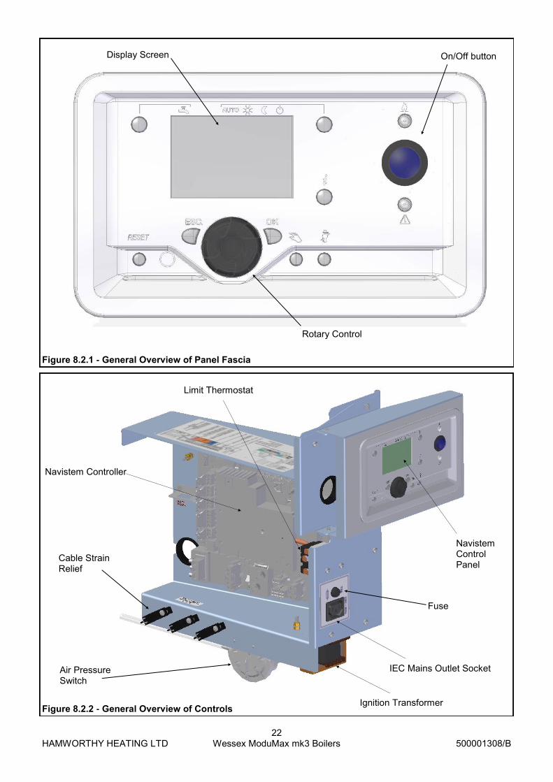
Figure 8.2.1 - General Overview of Panel Fascia
Figure 8.2.2 - General Overview of Controls
Limit Thermostat
IEC Mains Outlet Socket
Navistem Control Panel
Ignition Transformer
Navistem Controller
Air Pressure Switch
Cable Strain Relief
On/Off button Display Screen
Rotary Control
Fuse

HAMWORTHY HEATING LTD
23 Wessex ModuMax mk3 Boilers
500001308/B
8.2 CONTROLS OPERATION
Each ModuMax boiler is controlled by a Navistem boiler controller. The controller functions, settings and configurations are accessed via the rotary dial on the individual fascia panels (fig. 8.2.1) Comprehensive details and instructions on setting and using the boiler controller can be found in the separate Navistem instruction manual, HHL part no. 500001310, which is supplied with each boiler. A concise user instructions guide (HHL part no. 500001309) is supplied with each boiler. This guide gives instruction on initial set up as well as a list of possible error codes. The Navistem controller is located on the main control panel assembly which can be accessed after removal of the boiler front cover (fig.8.2.2). Note: Should remedial work be carried out on a module, then the non-firing module must be electrically isolated so as to prevent accidental operation in the event that the installation is required for ongoing heating requirements.

HAMWORTHY HEATING LTD
24 Wessex ModuMax mk3 Boilers
500001308/B
Figure 8.3.1 - Operating phases S
tand
by
TN
BTLO
TN
NS
TY
TH
L1
TV
TB
RE
TW
1TW
2TV
ZTS
A1
TS
A2
TI
MO
DTH
L2
TN
TN
2TH
L2A
TN
ATN
2TH
L1A
TW
1S
TV
KT
SA
FS
TO
E
12
34
68
910
11
12
13
14
15
16
17
19
24
18
22
24
710
523
20
21
ST
OE
SA
F
TLO
ST
OE
SA
F
TN
B
TN
N
ST
OE
SA
F
TN
B
ST
Y
TH
L1*
TH
L1A
*
ST
OE
SA
F
TN
B
TH
L1*
TH
L1A
*
KT
ST
V
ST
OE
SA
F
TN
B
TV
ST
OE
SA
F
TN
B
TB
RE
ST
OE
SA
F
TN
B
TW
1
ST
OE
SA
F
TN
B
TW
2
TV
Z
ST
OE
SA
F
TN
B
TV
Z
ST
OE
SA
F
TN
B
TS
A1
ST
OE
SA
F
TN
B
TS
A2
ST
OE
SA
F
TN
B
TI
ST
OE
SA
F
TN
B
TH
L2*
TH
L2A
*
MO
D
ST
OE
SA
F
TN
B
TH
L2*
TH
L2A
*
ST
OE
SA
F
TN
B
TN
ST
OE
SA
F
TN
B
TN
2
ST
OE
SA
F
TN
B
TH
L1*
TH
L1A
*
ST
OE
SA
F
TN
B
TN
A
ST
OE
SA
F
TN
B
TN
2
ST
OE
SA
F
TN
B
TH
L1*
TH
L1A
*
ST
OE
SA
F
TN
B
TW
1
ST
OE
SA
F
TN
B
TW
2
TV
Z
ST
OE
SA
F
TN
B
ST
OE
SA
F
TN
B
ST
OE
TN
B
Du
rati
on
9500
9517
9519
9518-
9519
9534
9540
9544
9540
9544
9652
120s
51s
51s
51s
51s
51s
51s
24h
51s
51s
51s
TH
L1*▲
▲T
HL1*▲
TH
L1*▲
TN
B▲
▼↑
TH
L1*▼
TH
L1*▼
▼▲
▲▲
▲
▼▲
▲
▼▲
TN
B▲
TN
B▲
Fan
sp
ee
d
Se
t p
oin
t9504
9504
9512
9512
9512
9512
9512
9512
9512
9524 ..
9529
9524 ..
9529
9524 ..
9529
9524 ..
9529
9504
9504
9524 ..
9529
9512
9512
9651
▼▼
▲▲
▼▼
▼
▲▲
▲
▼▼
To
lera
nce
tim
e2,8
s0,8
s2,8
s2,8
s2,8
s
Output
Ign
ite
r
Gas
Valv
e
Fanspeed supervision
N_V
orM
ax
N_V
or
N_V
L
N_Z
L
N_T
L
N_N
ull
Ne
xt
Ph
as
e
Input
He
at
De
man
d
Fla
me
LP
(2)
LP
(3)
LP
(4)
LP
(5)
GP
(1)
SL
T (
1)
SL
T (
2)
TN
B▲
Tim
eo
ut
Re
acti
on
LM
S.. S
eq
ue
nc
e d
iag
ram
fo
r b
urn
er
Se
qu
en
ce
Hom
e r
un
Sta
rtup
TS
AO
pera
tion
Shutd
ow
nS
hutd
ow
nS
tart
up
Sta
ndby
Err
or
Ph
as
e
Ph
ase-
No
.
ZZ Z
ZZ
ZZ
ZZ
ZZ
ZZ
ZZ
ZZ
ZZZ
ZZ
ZZ
Z
Z Z
RR
RR
RR
Q
RR
R R
RR
R
RR
R
R
Z
n
Nog_N
ull
-delta
-delta
-delta
+delta
+delta
ZG
Z
V
VR
ZZ
Z ZRR
G

HAMWORTHY HEATING LTD
25 Wessex ModuMax mk3 Boilers
500001308/B
8.4 Ignition Controller Check. 1. With the burner firing, the flame signal should be at least 3µA. Refer to separate Navistem manual,, HHL part no. 500001310. To check for correct operation of the ignition controller, close the gas valve. The boiler should shutdown after approximately one second and attempt a re-ignition. Check that the flame has been extinguished 2. Alternatively, the flame probe lead can be removed from the end of the flame probe, with the same result.
8.5 Gas Supply Pressure Check. 1. When the boiler modules have been checked for correct operation the gas supply pressure should be checked. This should be done with all modules firing.
For Natural Gas, a nominal gas inlet pressure of 20mbar measured at the rear of the boiler is required, with a maximum inlet pressure of 25mbar.
For LPG, a nominal gas inlet pressure of 37mbar measured at the rear of the boiler is required, with a maximum inlet pressure of 45mbar.
8.6 Combustion Checks “The boiler modules are factory pre-set, but site checks must be done to confirm correct performance.”
2. Use appropriate tool to remove sample point plug from front of combustion chamber (see arrow).
3. Ensure that an insertion distance of 200mm is set on the combustion analyser probe. NOTE: THIS DISTANCE MUST BE SET TO ENSURE ACCURATE ANALYSIS OF FLUE GASES.
Figure 8.6.1 - Removal of Sample Point Plug
Figure 8.6.2 - Combustion Analyser Probe Setting
4. Insert probe horizontally into combustion chamber until depth stop is met.
Figure 8.6.3 - Insertion of Analyser Probe
HAMWORTHY HEATING LTD
26 Wessex ModuMax mk3 Boilers
500001308/B
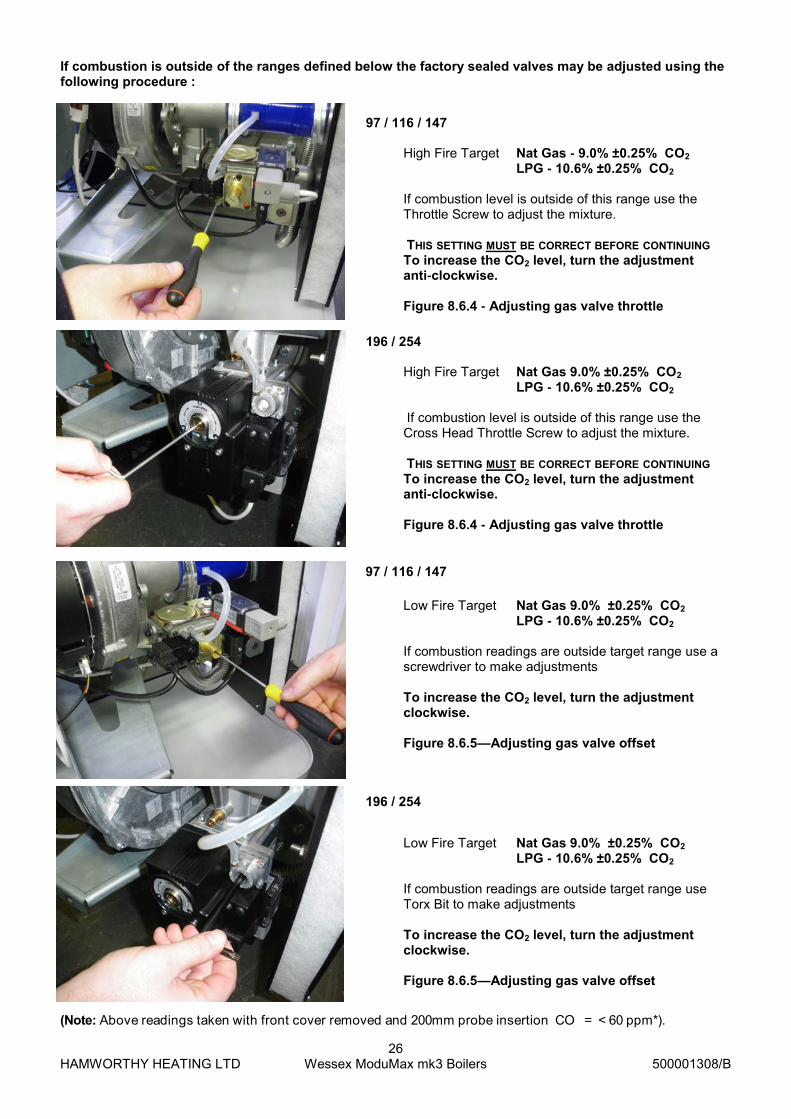
(Note: Above readings taken with front cover removed and 200mm probe insertion CO = < 60 ppm*).
High Fire Target Nat Gas - 9.0% ±0.25% CO2 LPG - 10.6% ±0.25% CO2 If combustion level is outside of this range use the Throttle Screw to adjust the mixture. THIS SETTING MUST BE CORRECT BEFORE CONTINUING To increase the CO2 level, turn the adjustment anti-clockwise. Figure 8.6.4 - Adjusting gas valve throttle
Low Fire Target Nat Gas 9.0% ±0.25% CO2
LPG - 10.6% ±0.25% CO2 If combustion readings are outside target range use a screwdriver to make adjustments To increase the CO2 level, turn the adjustment clockwise. Figure 8.6.5—Adjusting gas valve offset
97 / 116 / 147
97 / 116 / 147
196 / 254
196 / 254
If combustion is outside of the ranges defined below the factory sealed valves may be adjusted using the following procedure :
High Fire Target Nat Gas 9.0% ±0.25% CO2 LPG - 10.6% ±0.25% CO2
If combustion level is outside of this range use the Cross Head Throttle Screw to adjust the mixture. THIS SETTING MUST BE CORRECT BEFORE CONTINUING To increase the CO2 level, turn the adjustment anti-clockwise. Figure 8.6.4 - Adjusting gas valve throttle
Low Fire Target Nat Gas 9.0% ±0.25% CO2
LPG - 10.6% ±0.25% CO2 If combustion readings are outside target range use Torx Bit to make adjustments To increase the CO2 level, turn the adjustment clockwise. Figure 8.6.5—Adjusting gas valve offset

HAMWORTHY HEATING LTD
27 Wessex ModuMax mk3 Boilers
500001308/B
5. Energise electrical supply and start the boiler module. Refer to the user instructions for the boiler input level. 6. Monitor the combustion readings on the combustion analyser at both Maximum and Minimum firing rates. *Figure must not exceed 200ppm under normal operating conditions. If combustion readings fall within the required range the boiler module is set and operating correctly. If the combustion readings fall outside the required range the burner settings will require adjustment.
CONTACT HAMWORTHY HEATING TECHNICAL DEPARTMENT FOR FURTHER DETAILS 7. Shut down the boiler and isolate from the electrical supply. Remove instrumentation and replace test points and plugs. 8. Refer to section 8.1 - Controls Operation, to adjust the relevant boiler settings specific to the installation 8.7 User Instructions. When the boiler is fully commissioned, the owner or their representative should be made aware of the lighting-up and operating instructions. A practical demonstration should be given describing each functional step. This Installation and Commissioning guide, the servicing instructions manual and the user’s instructions should then be handed over and be kept in a safe place for future reference. 9.0 FAULT FINDING The Wessex ModuMax boiler is equipped with full self-diagnostic fault indication, with faults being allocated a code. A lockout will be denoted by a flashing LED on the fascia panel which will also be constantly illuminated by a block error - refer to the separate Navistem manual. The common fault codes are detailed in the separate user instructions guide. Fault codes not detailed in this manual should only be investigated by an Engineer.
Should a fault code appear which cannot be reset, or a fault code repeatedly occurs, contact Hamworthy Heating for assistance. Do not continue to operate or use the boiler
as this may cause damage to the controls.
9.1 Safety Temperature Limiter (Limit Thermostat) 1. The electronic control thermostat has several safety levels built in such that a controlled shutdown should occur before the safety temperature limiter is activated. Should these safety levels be overridden (say external pump overrun failure after shutdown) the safety temperature limiter will trip initiating a boiler shutdown, preventing the boiler from firing. A code on the controls display will flash indicating that the safety temperature limiter has tripped. 2. The limit thermostat (mounted on the control panel assembly - visible after removing the front cover) will automatically reset after the boiler returns to a normal operating temperature. 3. Always carry out an investigation to ascertain the reason for overheating. The most common cause of overheating lack of water flow rate through the boiler - possibly due to external pump problem. 9.2 Ignition Controller 1. The flame is under constant supervision by the burner ignition controller. The controller monitors the flame’s ability to rectify an AC current. If the flame diminishes for whatever reason and the rectified current drops below the controller’s minimum detection current (3µA DC), the controller will de-energise the gas control valve within 1 second and commence a restart. Failure to establish and detect a flame during the light-up sequence will result in burner shutdown and lockout within 5 seconds, requiring a manual reset to restart the ignition sequence. 2. If the boiler continues to lockout, then an investigation must be made to ascertain the cause. 3. A false flame signal at the start and during pre-purge will cause the boiler module to restart its ignition sequence at the end of the pre-purge period. If this occurs 3 times in succession the controls will disable operation of the boiler module, requiring reset of the module.

HAMWORTHY HEATING LTD
28 Wessex ModuMax mk3 Boilers
500001308/B
Figure 9.3- Wiring Diagram

HAMWORTHY HEATING LTD
29 Wessex ModuMax mk3 Boilers
500001308/B
10 SERVICING A competent person registered for working on non domestic gas appliances should check and ensure that the flue, its support and terminal, the ventilation to the boiler house, safety valve, drain, water filter if fitted, pressure gauge, etc.; are in a serviceable and working condition and still comply with the relevant standards and codes of practice - see Section 4. 10.1 Regular servicing is recommended, preferably by a Hamworthy appointed person, and at least annually, to ensure trouble free operation. For Wessex ModuMax, Hamworthy would recommend an additional 6 monthly examination following commissioning, acknowledging site conditions and running hours. Although cleaning of flue ways may not be necessary on a yearly basis, it is important that all controls and safety features are checked for correct operation. Note:- Measuring flue gas CO2 and gas temperatures will give an indication of the state of the boiler flue ways and waterways. Results should be compared with previously measured values to establish possible loss of efficiency. Should remedial work be carried out on a module, then the non-firing module must be electrically isolated so as to prevent accidental operation in the event that the installation is required for ongoing heating requirements. 10.2 Annual Service The procedure detailed relates to a single module and MUST be carried out on ALL individual modules which constitute a unit. Before servicing the boiler, the following procedure must be carried out :- WARNING: Isolate all electrical supplies and turn off the gas service valve. 1) Remove the front casing door by unscrewing the centre fixing. 2) Disconnect the H.S.I. and flame probe connectors from the respective probes. Remove the erath lead from the flame probe. 3) Disconnect the fan power supply and control leads from the fan taking care with the latch on each connector. 4) Check that the gas service valve is closed, then undo the lower connection union on the flexible hose (at gas service valve connection). 5) Carefully remove the electrical plug from the gas valve and remove the Low Gas Pressure Switch. 6) Remove the air inlet filter cassette. Refer to section 11.15 7) Remove the 2 M8 burner retaining nuts and carefully withdraw the complete burner/ fan assembly from the
heat exchanger. Separate the burner fabrication from the fan, venturi and gas control valve . 8) Remove and inspect H.S.I. and flame probe, ensure they are free from debris or deposits. Test resistance value of H.S.I. & if above 200 ohms (cold), replace with a lower resistance unit. Check respective positions – See Figure 10.2. Note:- The H.S.I. element is very fragile. 9) Check the burner and clean using a soft brush if required (if possible use a vacuum cleaner to remove the dust from inside the burner tube). After cleaning the inside, the burner tube can be washed using clean water. Tap the burner flange firmly downwards on a block of wood to dislodge any residual debris from inside the burner tube. A damaged or cracked burner should be replaced. Note:- Do not use a wire brush to clean the burner. 10) Check and clean the filter medium by washing in warm soapy water. DO NOT OPERATE THE BOILER WITH THE FILTER REMOVED! 11) Separate the gas valve from the venturi & ensure venturi mouth and gas feed tube are clean and free of obstruction. 12) Inspect the fan scroll and impellor, clean and check for damage. 13) Inspect the non return valve in the burner inlet duct for smooth operation. If venturi is removed it must be put back in exactly the same position. 14) Separate the inlet flange and elbow fitting from the gas control valve by removing the 4 M5 socket cap head screws. Check that the mesh inlet filter in the gas valve is clear of debris, remove any foreign objects caught in the filter. Re-assemble in reverse order taking care to inspect and if necessary, replace any o-rings, gaskets or seals. Refer to Section 8.4 onwards, Commissioning and Testing, and test all gas joints broken or disturbed for soundness before firing. Carry out a combustion check by testing the flue gas CO2 and CO levels as detailed from Section 8.4. 10.3 Four Year Service Repeat the annual service as previously described but do not refit any components to the heat exchanger. 10.3.1 To clean the heat exchanger, the use of a high pressure water hose (40-80 psi) is recommended. However provision must be made for the drainage of water used in this process. At the rear of the boiler module remove the condensate drain trap assembly

HAMWORTHY HEATING LTD
30 Wessex ModuMax mk3 Boilers
500001308/B
from the casing by unfastening the 2 M6 nuts, to expose the opening in the casing. The cleaning water and any debris will exit the casing through this opening. On completion ensure that the opening is clear of debris and refit the condensate drain trap assembly, renewing the gasket if required. 10.3.2 Should a high pressure hose not be available, the heat exchanger will have to be removed from the module casing. Isolate the heat exchanger from the flow and return water pipework and drain down. Remove all fittings from the water flow and return connections (including sensors and pockets) and remove the safety valve (if fitted) or ¾” cap. Unfasten the 10 M8 nuts securing the water connection sealing plates and the safety valve pipe sealing plate, and remove all sealing plates and o-rings. The boiler heat exchanger assembly is heavy, 97 & 116 weigh 100kg each & 147/196/254 weigh 130kg. It is recommended that a suitable lifting apparatus is used to support the weight of the heat exchanger, an M12 lifting eye nut can be fitted to the M12 stud at the top of the heat exchanger front plate for this purpose. Before connecting the lifting equipment to the lifting eye, hang a new heat exchanger to casing sealing gasket over the lifting eye, with the adhesive side facing the boiler. This will enable the new gasket to be fitted on re-assembly without cutting it! Remove the 6 M10 nuts that retain the heat exchanger
into the boiler module casing, and with the front end supported slowly withdraw the heat exchanger until the rear of the stainless steel baffles are visible. With the rear of the heat exchanger resting in the body of the boiler and the front supported by the lifting apparatus, access is gained for removal of the stainless steel baffles. The silicon sealant between the baffle and the end plates must be peeled away, before attempting to remove the baffles. Unhook the stainless steel springs and remove the baffle plates to expose the finned tube bank. Wire brush both sides of the baffles to remove any deposits. Thoroughly wire brush the finned tubes and ensure that all debris is removed from the centre of the heat exchanger. Remove the heat exchanger from the boiler body. The heat exchanger tubes are stainless steel. Remove the bolts and nuts securing the heat exchanger front cover plate. Remove the bolts securing the heat exchanger rear cover plate. Clean and de-scale all surfaces of the heat exchanger tube header castings and cover plates, and internal surfaces of the finned tubes and water connection nipples. Chemical de-scaling is preferred for the tube bank assembly. Note: Always follow the chemical manufacturer’s instructions to ensure correct application and safety. Re-assemble the baffle plates by fitting one of the stainless steel springs and inserting the baffles beneath it, then fitting the second spring. When all the baffles are
Figure 10.2 - Hot Surface Igniter and Flame Sensing Probe Positions
HAMWORTHY HEATING LTD
31 Wessex ModuMax mk3 Boilers
500001308/B
in place the gap between the ends of the baffle and the end plates must be sealed with silicon sealant. Remove the existing heat exchanger to casing sealing gasket and fit the new gasket previously hung on the lifting eye. Clean mating surfaces of the heat exchanger tube header castings and cover plates. Re-assemble the heat exchanger assembly using new gaskets. Ensure that the cover plates are re-fitted in the correct orientation. Evenly torque the bolts and nuts to 7kg m.
Refit heat exchanger ensuring correct rotational orientation, so that the water connection nipples and safety valve pipe pass through the holes in the rear of the casing, fastening in place with the 6 M10 nuts. Refit the water connection and safety valve pipe sealing plates, renewing all gaskets and o-rings. Reconnect the system pipework and check for soundness.
Ensure that the cover plates are re-fitted in the correct orientation. Evenly torque the bolts and nuts to 7kg m.
Re-fit the burner assembly. Test all gas joints broken or disturbed for soundness before firing.
Refer to Section 8 Commissioning The Boiler, for correct procedures.
11.0 REPLACEMENT OF FAILED COMPONENTS
There are a number of components listed below which can be replaced simply and quickly by following the given procedure. In each case the operation of each replaced component must be checked by carrying out the appropriate part of the commissioning procedure. See Section 8: COMMISSIONING & TESTING.
Note:- Isolate all electrical supplies to the boiler module before removing the front cover and commencing any servicing or component exchange procedure. With the front cover removed, turn off the gas supply at the service valve.
11.1 Hot Surface Igniter and Flame Probe Assembly Part Nos. 563801019 & 533805021
Note:- The igniter and flame probe ceramics are very fragile.
Unplug the igniter from the harness, remove the single socket cap head screw securing the igniter to the burner flange and withdraw the igniter. When fitting the replacement carefully feed the igniter through the mounting hole and secure with the socket cap head screw. Flame Probe - The only maintenance which can be carried out is to clean the wire of any deposits with an abrasive paper, taking care not to damage the electrode. A typical flame current is 10µA, (high fire) with the lockout threshold at 3µA, Disconnect the flame probe lead & earth lead, remove the single socket cap head screw securing the probe to
the burner flange and withdraw the probe. When fitting the replacement carefully feed the probe through the mounting hole taking care not to damage the ceramic.
Note:- Do not remove both securing screws at the same time as the separate flange and Mica sight glass will become detached.
Ensure the positions of the igniter and probe are as recommended in Figure 10.2. 11.2 Flow / Return sensor Part No. 533901431
The two identical sensors are located in pockets on the flow and return pipes at the rear of the boiler. To remove the sensor, unplug the sensor from the harness, loosen the M3 screw securing the sensor in the pocket and withdraw the sensor. Upon replacement ensure that the sensor is fully engaged and secured into the pocket.
11.3 Temperature Limiter (Limit Stat) Part No. 531040016
To replace the limiter, remove the boiler front cover to expose the control panel assembly. Remove the electrical connections from the limiter body noting the position of the coloured cables. Unclip and remove the thermostat bulb from the pocket in the front of the heat exchanger. Undo the 2 fixing screws in the front of the control panel and remove the unit. Check the operation of the replacement device by carefully applying a heat source to the bulb. The temperature of the replacement limit stat is factory set and will not require adjustment. Fit the replacement limiter in reverse order ensuring that the electrical connections are in the correct positions. 11.4 Gas Valve Part No. 533903044 (97, 116 & 147) Part No. 533903036(196 & 254)
Note:- Some gas valve components can be replaced without completely removing the whole assembly from the boiler. However, Hamworthy Heating strongly recommend that a complete new gas valve is fitted to ensure safe, reliable operation of the boiler. Please refer to Hamworthy Heating Technical Department before attempting to remove components from the gas valve.
Ensure that the boiler module electrical power and gas supplies are isolated. Unfasten the gas valve plug securing screws and disconnect the plug by pulling firmly away from the valve. Unfasten the low gas pressure switch plug and remove the low gas pressure switch from the gas valve (97/116/147 only) by removing the securing screw.
Remove the 4 M5 cap head screws securing the gas valve to the gas inlet flange, allow the flange to hang

HAMWORTHY HEATING LTD
32 Wessex ModuMax mk3 Boilers
500001308/B
free on the flexible gas pipe. Remove the 4 M5 cap head screws securing the gas valve to the gas feed pipe, taking care to support the weight of the valve. Note that the cap head screws are different lengths at the inlet and outlet of the valve, be sure to replace at the correct positions. Replace the gas valve complete with new ‘O’ rings, ensuring correct orientation - gas flow is in the same direction as the arrow marked on the valve. Replace the LPG orifice, if fitted. Replace the gas valve leads, ensuring correct plug positions and orientation, and secure firmly with the retained screws. Refit the low gas pressure switch (97/116/147 only) and secure the electrical plug with the retaining screw.
Check the setting of the gas supply pressure switch, and adjust if necessary. Unfasten the single pozi pan head screw to remove the cover if adjustment is required. Replace the cover after setting the switch to 97/116/147 - 7mb 196/254 - 7.5mb Switch on the boiler module gas supply and check for integrity of all joints using a proprietary leak detector. Refer to Figure 7.1 if necessary for valve integrity check procedure. Switch on the boiler module electrical power supply and ensure gas valve operation is correct and safe before continuing. Re-light the boiler module. For correct settings and procedures refer to Section 8.0 Commissioning The Boiler.
11.5 Combustion Fan Part No. 533704014 - (97/116/147) Part No. 533704003 - (196/254)
Ensure that the boiler module electrical power supply is isolated before removing the front cover and gaining access to the controls. 97/116/147 Disconnect the fan power supply and control leads from the fan. Remove the 3 M6 hex head screws, nuts and washers fastening the venturi to the gas valve. Remove the 4 M5 screws securing the fan outlet to the burner flange and remove the fan. 196/254 Disconnect the fan power supply and control leads from the fan. Separate the venturi and gas control valve from the fan by unfastening the 6 M8 socket dome head screws. Make provision to support the weight of the venturi and gas control valve whilst not connected to the fan. Remove the 4 M8 hex head screws, nuts and washers fastening the fan to the burner and remove the fan.
Fit the replacement in reverse order, and if required replace any seals or gaskets.
Note:- After re-making any gas or combustion circuit joint/connection, an integrity check is recommended to ensure safety.
11.6 Venturi Part No. 532418007 - (97/116/147) Part No. 532418001 - (196/254) Ensure that the boiler module electrical power supply is isolated before removing the front cover and gaining access to the controls. Isolate the boiler module gas supply by closing the gas service valve. Remove the 4 M5 socket cap head screws from the venturi gas inlet flange and separate the gas control valve from the venturi. Make provision to support the weight of the valve assembly whilst not connected to the venturi. Separate the venturi from the fan by unfastening the 6 M8 socket dome head screws. Fit the replacement in reverse order, and if required replace any seals or gaskets.
11.7 Burner Part No. 533301019 - (97 & 116) Part No. 533301020 - 147 Part No. 533301021 - 196 Part No. 533301024 - 254
Disconnect the H.S.I. and flame probe connectors from the respective probes. Disconnect the fan power supply and control leads from the fan taking care with the latch on each connector.
Unscrew retaining screws and remove the electrical plugs from the gas valve and low gas pressure switch. 97 & 116 Check that the gas service valve is closed, then undo the lower connection union on the flexible hose (at gas control valve inlet elbow). Separate the burner fabrication from the fan . 147/196/254 Undo the lower connection union on the flexible hose (at gas control valve inlet elbow). Remove the 2 M8 burner retaining nuts and carefully withdraw the complete burner assembly from the heat exchanger. Separate the burner fabrication from the fan, venturi and gas control valve. Note the assembly of the non return valve in the burner inlet duct. Inspect the non return valve for smooth operation. Remove and inspect H.S.I. and flame probe, ensure they are free from debris or deposits. Test resistance value of H.S.I. if above 200 ohms (cold), replace with a lower resistance unit. Check respective positions – See Figure 13.2.
Note:- The H.S.I. element is very fragile. A damaged or cracked burner should be replaced. Replace components in reverse order using new gaskets. 11.8 Ignition Transformer Part No. 533901441 Ensure that the boiler module electrical power supply is isolated before removing the front cover and gaining access to the controls.

HAMWORTHY HEATING LTD
33 Wessex ModuMax mk3 Boilers
500001308/B
Unplug the electrical connections to the transformer noting the orientation and relative positions. Remove the two pozi pan head screws securing the transformer to the control panel and withdraw. Fit the new unit in reverse order. Re-light the boiler and check for correct operation. 11.9 Main Control - Navistem Part Number Model 533901756 - WM97 533901758 - WM116 533901760 - WM147 533901762 - WM196 533901764 - WM254
Ensure that the boiler module electrical power supply is isolated before removing the front cover and gaining access to the controls. Also ensure that all other supplies, particularly to the volt free contact outputs, are also isolated.
If a ‘Clip in Module‘ is fitted, this must first be removed. Carefully disconnect the plug securing the clip-in to the Navistem Depress the locking latch at the connector end of the clip in to allow the module to be hinged up and disengaged from the Navistem. Unplug the electrical connections to the PCB noting the orientation and relative positions. Fit the replacement PCB in reverse order as described above. Remember to apply the parameters local to the installation on initialisation - refer to the separate Navistem manual. Re-light the boiler and check for correct operation. 11.10 Clip in Modules Part No. 533901776- Extension module AGU2.550A109 Part No. 533901456 - LPB module OCI345.06/101
Ensure that the boiler module electrical power supply is isolated before removing the front cover and gaining access to the controls. Carefully disconnect the plug securing the clip-in module to the Navistem
Carefully disconnect the plug from the top of the clip-in module.
Depress the locking latch at the connector end of the clip in to allow the module to be hinged up and disengaged from the Navistem or control panel. Assemble in reverse order.
11.11 Display screen Part Number 533901691
Ensure that the boiler module electrical power supply is isolated before removing the front cover and gaining access to the controls.
Carefully disconnect the ribbon cable connecting the screen to the Navistem controller and the connectors to the power switch. Remove the 4 screws securing the screen panel to the controls pod. Unclip the screen from the panel of the controls fascia and remove the display pcb. Remove the ribbon cable plug from the pcb and replace the display in reverse order. 11.12 Low Gas Pressure Switch Part No. 533901497 - 97/116/147 Part No. 533925004 - 196/254
Ensure that the boiler module electrical power supply is isolated before removing the front cover and gaining access to the controls. Isolate the boiler module gas supply by closing the gas service valve. 97/116/147 Disconnect the electrical plug after removing the securing screw. Remove the switch securing screw and withdraw the switch from the Brass adaptor. Fit the replacement switch in reverse order using new ‘O’ rings. 196/254 Disconnect the electrical plug after removing the securing screw. Remove the screw(s) securing the switch to the gas valve body. Fit the replacement switch in reverse order using new ‘O’ rings. Set to correct pressure - refer to Appendix A.
11.13 Air Pressure Switch Part Number 532496004
Ensure that the boiler module electrical power supply is isolated before removing the front cover and gaining access to the controls. Disconnect the sensing tube from the switch (P1) noting the position. Disconnect the electrical connections (1&2)noting their position. Remove the 2 screws securing the pressure switch body to the control bracket and remove the switch. Fit the replacement unit in reverse order.
P1
2
1

HAMWORTHY HEATING LTD
34 Wessex ModuMax mk3 Boilers
500001308/B
11.14 Ignition Transformer In-line Fuse Part No. 533922013 The boiler is equipped with an in-line fuse fitted between the ignition transformer and the main LMS. This T1A rated fuse can be located on the control panel once the front cover is removed. The condition of the fuse should be checked when a possible LMS malfunction has been diagnosed. Fig. 11.14 In-line Fuse
11.15 Air Inlet Filter Replacement Filter Material Part No. 532812016 The ModuMax mk3 is fitted with an air inlet filter which is accessed after removing the main front cover of the boiler. The White filter material can be replaced at service intervals by ordering the part number above available from Hamworthy Heating Ltd spares department. Remove the retaining pin from the top corner of the filter and replace with the new, clean material. Re-place the retaining pin. Fig. 11.15 Air Filter
In-Line Fuse Air Filter Media
Filter Media Retaining Pin
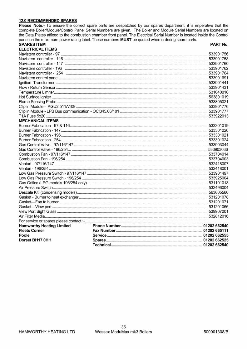
HAMWORTHY HEATING LTD
35 Wessex ModuMax mk3 Boilers
500001308/B
12.0 RECOMMENDED SPARES Please Note:- To ensure the correct spare parts are despatched by our spares department, it is imperative that the complete Boiler/Module/Control Panel Serial Numbers are given. The Boiler and Module Serial Numbers are located on the Data Plates affixed to the combustion chamber front panel. The Electrical Serial Number is located inside the Control panel on the maximum power rating label. These numbers MUST be quoted when ordering spare parts. SPARES ITEM PART No. ELECTRICAL ITEMS Navistem controller - 97 .................................................................................................................................................... 533901756 Navistem controller- 116 ................................................................................................................................................ 533901758 Navistem controller - 147 ................................................................................................................................................ 533901760 Navistem controller - 196 ................................................................................................................................................ 533901762 Navistem controller - 254 ............................................................................................................................................... 533901764 Navistem control panel ...................................................................................................................................................... 533901691 Ignition Transformer ......................................................................................................................................................... 533901441 Flow / Return Sensor ......................................................................................................................................................... 533901431 Temperature Limiter ........................................................................................................................................................... 531040016 Hot Surface Igniter ............................................................................................................................................................. 563801019 Flame Sensing Probe ........................................................................................................................................................ 533805021 Clip in Module - AGU2.511A109 ..................................................................................................................................... 533901776 Clip in Module - LPB Bus communication - OCI345.06/101 ......................................................................................... 533901777 T1A Fuse 5x20 ................................................................................................................................................................... 533922013 MECHANICAL ITEMS Burner Fabrication - 97 & 116 ........................................................................................................................................... 533301019 Burner Fabrication - 147 .................................................................................................................................................... 533301020 Burner Fabrication - 196 .................................................................................................................................................... 533301021 Burner Fabrication - 254 .................................................................................................................................................... 533301024 Gas Control Valve - 97/116/147 ....................................................................................................................................... 533903044 Gas Control Valve - 196/254... ........................................................................................................................................ 533903036 Combustion Fan - 97/116/147 .......................................................................................................................................... 533704014 Combustion Fan - 196/254 ............................................................................................................................................... 533704003 Venturi - 97/116/147 .......................................................................................................................................................... 532418007 Venturi - 196/254 ................................................................................................................................................................ 532418001 Low Gas Pressure Switch - 97/116/147 .......................................................................................................................... 533901497 Low Gas Pressure Switch - 196/254 ............................................................................................................................... 533925004 Gas Orifice (LPG models 196/254 only) .......................................................................................................................... 531101013 Air Pressure Switch ............................................................................................................................................................ 532496004 Descale Kit (condensing models) .................................................................................................................................... 563605560 Gasket - Burner to heat exchanger .................................................................................................................................. 531201078 Gasket—Fan to burner ...................................................................................................................................................... 531201071 Gasket—View port ............................................................................................................................................................. 531201066 View Port Sight Glass ........................................................................................................................................................ 539907001 Air Filter Media .................................................................................................................................................................... 532812016 For service or spares please contact :- ................................................................................................................................................ Hamworthy Heating Limited Phone Number.................................................................................. 01202 662540 Fleets Corner Fax Number ....................................................................................... 01202 665111 Poole Service ................................................................................................ 01202 662555 Dorset BH17 0HH Spares................................................................................................. 01202 662525
Technical............................................................................................ 01202 662540

HAMWORTHY HEATING LTD
36 Wessex ModuMax mk3 Boilers
500001308/B
APPENDIX A - GAS DATA
GAS DATA 97 116 147 196 254
Gas Inlet Connection Pipe Thread Size R1” R1 1/4”
Nominal Inlet Pressure Nat Gas (LPG) -mbar 20 (37)
Maximum Inlet Pressure Nat Gas (LPG) -mbar 25 (45)
Gas Pressure Switch Setting Nat Gas -mbar 7 7 7 5 5
Gas Flow Rate (max. per module) Nat Gas -m3/h 10.4 12.7 15.5 20.9 26.2
Gas Flow Rate (max. per module) LPG -m3/h 4.0 4.9 6.0 8.1 10.1
Target CO2 % at High / Low fire Nat Gas ±0.25% 9.0
Target CO2 % at High / Low fire LPG ±0.25% 10.6
NOx emission at 0% O2 (dry) Nat Gas mg/kWh 39.8 34.3 37.7 39.9 38.8
NOx emission at 0% O2 (dry) LPG mg/kWh 42.0 58.1 69.3 68.6 39.9
GENERAL DATA BOILER MODEL
Model - Condensing 97/194 97/291 97/97
Nat Gas LPG Nat Gas LPG Nat Gas LPG
Boiler Input (maximum) - kW (Gross) 109.0 106.7 218.0 213.4 327.0 320.1
Boiler Input (maximum) - kW (Nett) 98.2 98.2 196.4 196.4 294.6 294.6
Boiler Output kW (maximum) condensing 50/30°C - kW 97.2 97.2 194.4 194.4 291.6 291.6
Boiler Output kW (maximum) non condensing 80/60°C - kW 95.7 95.7 191.4 191.4 287.1 287.1
Boiler Module Output (minimum) 80/60°C kW 19.1
Model - Condensing 116/116 116/232 116/348
Nat Gas LPG Nat Gas LPG Nat Gas LPG
Boiler Input (maximum) - kW (Gross) 133.0 130.2 266 260.4 399 390.5
Boiler Input (maximum) - kW (Nett) 119.8 119.8 239.6 239.6 359.4 359.4
Boiler Output kW (maximum) condensing 50/30°C - kW 116.2 116.2 232.5 232.5 348.7 348.7
Boiler Output kW (maximum) non condensing 80/60°C - kW 115.2 115.2 230.4 230.4 345.6 345.6
Boiler Module Output (minimum) 80/60°C - kW 23.5
Model - Condensing 147/147 147/294 147/441
Nat Gas LPG Nat Gas LPG Nat Gas LPG
Boiler Input (maximum) - kW (Gross) 163.0 159.5 326 319.1 489 478.6
Boiler Input (maximum) - kW (Nett) 146.8 146.8 293.6 293.6 440.3 440.3
Boiler Output kW (maximum) condensing 50/30°C - kW 147.4 147.4 294.8 294.8 442.2 442.2
Boiler Output kW (maximum) non condensing 80/60°C - kW 142.8 142.8 285.6 285.6 428.4 428.4
Boiler Module Output (minimum) 80/60°C - kW 28.7
Model - Condensing 196/196 196/392 196/588
Nat Gas LPG Nat Gas LPG Nat Gas LPG
Boiler Input (maximum) - kW (Gross) 219.0 214.4 428.7 394.4 657 643.1
Boiler Input (maximum) - kW (Nett) 197.2 197.2 394.4 394.4 591.6 591.6
Boiler Output kW (maximum) condensing 50/30°C - kW 196.3 196.3 392.6 392.6 588.9 588.9
Boiler Output kW (maximum) non condensing 80/60°C - kW 191.6 191.6 383.2 383.2 574.8 574.8
Boiler Module Output (minimum) 80/60°C - kW 38.6
Model - Condensing 254/254 254/508 254/762
Nat Gas LPG Nat Gas LPG Nat Gas LPG
Boiler Input (maximum) - kW (Gross) 275.0 269.2 550 538.3 825 807.5
Boiler Input (maximum) - kW (Nett) 247.6 247.6 495.3 495.3 742.9 742.9
Boiler Output kW (maximum) condensing 50/30°C - kW 254.4 254.4 508.7 508.7 763.1 763.1
Boiler Output kW (maximum) non condensing 80/60°C - kW 239.8 239.8 479.6 479.6 719.4 719.4
Boiler Module Output (minimum) 80/60°C - kW 48.4
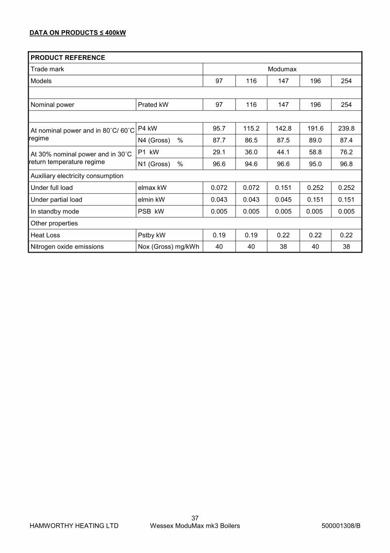
HAMWORTHY HEATING LTD
37 Wessex ModuMax mk3 Boilers
500001308/B
PRODUCT REFERENCE
Trade mark Modumax
Models 97 116 147 196 254
Nominal power Prated kW 97 116 147 196 254
At nominal power and in 80˚C/ 60˚C regime
P4 kW 95.7 115.2 142.8 191.6 239.8
N4 (Gross) % 87.7 86.5 87.5 89.0 87.4
At 30% nominal power and in 30˚C return temperature regime
P1 kW 29.1 36.0 44.1 58.8 76.2
N1 (Gross) % 96.6 94.6 96.6 95.0 96.8
Auxiliary electricity consumption
Under full load elmax kW 0.072 0.072 0.151 0.252 0.252
Under partial load elmin kW 0.043 0.043 0.045 0.151 0.151
In standby mode PSB kW 0.005 0.005 0.005 0.005 0.005
Other properties
Heat Loss Pstby kW 0.19 0.19 0.22 0.22 0.22
Nitrogen oxide emissions Nox (Gross) mg/kWh 40 40 38 40 38
DATA ON PRODUCTS ≤ 400kW
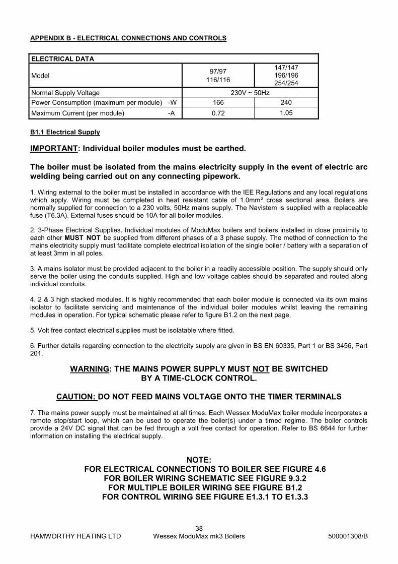
HAMWORTHY HEATING LTD
38 Wessex ModuMax mk3 Boilers
500001308/B
APPENDIX B - ELECTRICAL CONNECTIONS AND CONTROLS
ELECTRICAL DATA
Model 97/97
116/116
147/147 196/196 254/254
Normal Supply Voltage 230V ~ 50Hz
Power Consumption (maximum per module) -W 166 240
Maximum Current (per module) -A 0.72 1.05
B1.1 Electrical Supply
IMPORTANT: Individual boiler modules must be earthed. The boiler must be isolated from the mains electricity supply in the event of electric arc welding being carried out on any connecting pipework. 1. Wiring external to the boiler must be installed in accordance with the IEE Regulations and any local regulations which apply. Wiring must be completed in heat resistant cable of 1.0mm² cross sectional area. Boilers are normally supplied for connection to a 230 volts, 50Hz mains supply. The Navistem is supplied with a replaceable fuse (T6.3A). External fuses should be 10A for all boiler modules.
2. 3-Phase Electrical Supplies. Individual modules of ModuMax boilers and boilers installed in close proximity to each other MUST NOT be supplied from different phases of a 3 phase supply. The method of connection to the mains electricity supply must facilitate complete electrical isolation of the single boiler / battery with a separation of at least 3mm in all poles. 3. A mains isolator must be provided adjacent to the boiler in a readily accessible position. The supply should only serve the boiler using the conduits supplied. High and low voltage cables should be separated and routed along individual conduits. 4. 2 & 3 high stacked modules. It is highly recommended that each boiler module is connected via its own mains isolator to facilitate servicing and maintenance of the individual boiler modules whilst leaving the remaining modules in operation. For typical schematic please refer to figure B1.2 on the next page. 5. Volt free contact electrical supplies must be isolatable where fitted. 6. Further details regarding connection to the electricity supply are given in BS EN 60335, Part 1 or BS 3456, Part 201.
WARNING: THE MAINS POWER SUPPLY MUST NOT BE SWITCHED BY A TIME-CLOCK CONTROL.
CAUTION: DO NOT FEED MAINS VOLTAGE ONTO THE TIMER TERMINALS
7. The mains power supply must be maintained at all times. Each Wessex ModuMax boiler module incorporates a remote stop/start loop, which can be used to operate the boiler(s) under a timed regime. The boiler controls provide a 24V DC signal that can be fed through a volt free contact for operation. Refer to BS 6644 for further information on installing the electrical supply.
NOTE: FOR ELECTRICAL CONNECTIONS TO BOILER SEE FIGURE 4.6
FOR BOILER WIRING SCHEMATIC SEE FIGURE 9.3.2 FOR MULTIPLE BOILER WIRING SEE FIGURE B1.2
FOR CONTROL WIRING SEE FIGURE E1.3.1 TO E1.3.3

HAMWORTHY HEATING LTD
39 Wessex ModuMax mk3 Boilers
500001308/B
Figure B1.2 - External Control Wiring for Multiple Module Installation
LNE
3
3
3
2
2
1
1
2
1
H1
H1
H1
External Control
OptionalExternal
Control
Boiler 1LMS
Boiler 2LMS
Boiler 3LMS
0~10V
0~10V
0~10V
ControlSignal0~10V
orEnable
Note:- each module requires independent isolation of electrical supply and control signals. Signal cables must not be run in the same conduit as mains voltage cables
Option 1 - reference should be made to Building Regulations and CIBSE Guide
‘Energy Efficiency in Buildings’ for controls requirements. All modules must be sequenced. Enable - will give On/Off control of the modules
0~10V - will give modulation control of each module Option 2 provides modulation control of up to 16 modules.
Local Isolator
Option 1 Remote ControlOption 2 Merley Cascade Control
LPBBus
Control Signal0-10V or enable
H5
H5
H5
:

HAMWORTHY HEATING LTD
40 Wessex ModuMax mk3 Boilers
500001308/B
* Note:- Flue gas volumes are corrected to a flue gas temperature of 15°C, @ 9.1% CO2 and barometric pressure of 1013.25mbar.
FLUE DATA - Natural Gas 97 116 147
Model - Condensing 97 196 291c 116 232c 348c 147 291c 441c
Nominal Flue Diameter- mm 100 180 180 100 180 180 150 250 250
Maximum Flue Gas Temperature- °C 83 83 78
Pressure at the boiler flue outlet- Pa/mbar 150 / 1.5 150/1.5 150/1.5
Approx. Flue Gas Volume m3/h* 143 286 429 160 320 480 214 428 642
196 254
Model - Condensing 196 392c 588c 254 508c 762c
Nominal Flue Diameter- mm 150 250 250 150 250 250
Maximum Flue Gas Temperature- °C 83 82
Pressure at the boiler flue outlet- Pa/mbar 150/1.5 150 / 1.5
Approx. Flue Gas Volume m3/h* 279 558 837 354 708 1062
APPENDIX C - FLUE DATA
Natural Gas & LPG
C1.0 FLUE SYSTEM 1. Detailed recommendations for flue systems are given in BS 6644, and IGE/UP/10. All flue discharges for plant exceeding 150kW output must comply with the third edition of the 1956 Clean Air Act Memorandum.
WARNING: THE FLUE DISCHARGE FROM A MODUMAX BOILER WILL GENERATE A PLUME AT THE TERMINAL EXIT. THIS MUST BE CONSIDERED WITH REGARD TO TER-
MINAL LOCATION AND ADJACENT BUILDING FABRIC. C1.1 General Requirements The Hamworthy Wessex ModuMax series of boilers are designed to be used with natural draught flues. Flue systems should be designed in accordance with regulations and with reference to BS 6644 and IGE/UP/10. Open (Natural draught ) Flue. Type B23: Intake from ventilated plant room and discharge via horizontal/vertical flue. – Fig C1.1.2 Type B23p: Flue pressurised, intake from ventilated plant room and discharge via horizontal/vertical flue.– Fig C1.1.2 The connection to the boiler is suitable for 100mm flue duct (97 & 116) & 150mm flue duct (147/196/254), for connection to an open flue (chimney) system . The resistance of the flue system components is detailed in Figure C1.1.1 The following points should be noted: a. Due to the high thermal efficiency of the boiler condensation in the flue will occur. It is strongly recommended that twin wall or insulated flue pipe is used on all installations. b. Care should be taken to ensure that the flue is installed such that any condensation is continuously drained. All flues should have a minimum slope of 3° upwards in the direction of the exhaust gas flow (no horizontal sections). All joints should be such that any condensation is directed back down the slope to an open drain connection in the flue. The drain pipe must be manufactured from a corrosion resistant material and be at least 15mm diameter. It must also have a fall of at least 2-3° (approx. 30-50mm per meter) and connect to a drain via a waste trap. c. Boiler flue outlet sizes - A flue system designed with the same diameter as the boiler flue outlet may not provide satisfactory performance in all applications. Conversely a flue system designed with a smaller diameter than the boiler flue outlet may provide satisfactory performance. Consideration must be given to the correct calculation of the required flue size. If in any doubt consult Hamworthy Heating Ltd who working in partnership with Midtherm Engineering Ltd can provide a comprehensive flue design and installation package.

HAMWORTHY HEATING LTD
41 Wessex ModuMax mk3 Boilers
500001308/B
C1.2 Waste Gas Volume and Temperature. It is recommended that the volume and temperature of the waste gases used for design of the flue system are as given in the above tables. C1.3 Materials. Materials used for the flue system must be mechanically robust, resistant to internal and external corrosion, non-combustible and durable under the conditions to which they are likely to be subjected. Consideration must be given to avoid possible freezing of condense water traps and pipework
WARNING: THE FLUE SYSTEM MUST BE SELF SUPPORTING AND NOT PRESENT A RISK TO PEOPLE IN OR AROUND THE BUILDING.
C1.4 Suction The maximum number of Modules firing into a common chimney is 9. (IM11/IGEUP10 states 8 for a natural draft flue). For larger installations refer to HHL Technical. The flue system referred to in Table C1.1 must be designed acknowledging that there is a positive pressure generated by the boiler combustion fan. It is recommended that a draught stabiliser is fitted to the flue system where the suction is likely to be negative at the boiler connection. Any stabiliser fitted must be in or close to the vertical chimney. The flue system must be designed to limit the maximum suction (cold) to 30Pa negative, measured at the connection to the boiler. Should the suction be greater than 30Pa, refer to HHL technical. This condition must then be checked Hot and with all boilers firing, the maximum pressure condition at the connection to the boiler is 150Pa positive. In the event that the flue system when Hot does generate a suction, the maximum suction is 100Pa. Fan Dilution - The design must provide for the use of balancing and trim dampers, and their location and operation must be such that the constraints detailed above can be met. Care must be taken to ensure that the fan performance is matched to deliver the appropriate dilution, whilst ensuring that excessive suction is not applied to the boilers. If in doubt, refer to HHL Technical. C1.5 Disconnection Provisions should be made for disconnection of the flue pipe for servicing. It is advisable that bends are fitted with removable covers for inspection and cleaning as appropriate. C1.6 Flue Discharge The flue system must ensure safe and efficient operation of the boiler to which it is attached, protect the combustion process from wind effects and disperse the products of combustion to the external air. The flue must terminate in a freely exposed position and be so situated as to prevent the products of combustion entering any opening in a building. Where the flue diameter is less than 204mm (8”) diameter a terminal must be fitted. Where the flue is of a larger size, consideration should be given to the fitting of a flue discharge terminal or grille to stop ingress of birds etc. C1.7 Surface Temperatures Combustible materials in the vicinity of the boiler and flue shall not exceed 65°C during boiler operation. The flue shall not be closer than 50mm to any combustible material, except where it passes through such material with a non-combustible sleeve when the air gap may not be less than 25mm.

HAMWORTHY HEATING LTD
42 Wessex ModuMax mk3 Boilers
500001308/B
C1.8 Location The flue system must not be placed or fitted where there is undue risk of accidental damage to the flue pipe or undue danger to persons in the vicinity. Check that the flue and chimney are clear from any obstruction. Wessex ModuMax boilers are suitable for installation in a balanced compartment in accordance with the requirements of BS 6644. Consult Hamworthy Heating Technical Department for help or assistance if in doubt. C1.9. Condensate Discharge
Due to the high thermal efficiency of the boiler, condensation will occur within the boiler casing during firing from cold conditions. A drain with an integral trap is fitted to the rear of each module suitable for connection to a 32mm plastic waste pipe (not Hamworthy Heating Ltd supply), which must be connected to a tundish (not Hamworthy Heating Ltd supply). Discharge piping from a tundish should be of synthetic material due to the mild acidity of the condensate (pH3-5), with all discharge piping having a minimum fall of 30mm/m away from the boiler. Consideration should be given to possible freezing of condense water traps and pipework. This must be avoided at all times by routing pipework within the building, where possible. In addition to the above the stacked module arrangement flue boxes are supplied with a trap terminating in a 32mm i.d. connection, which should be connected in a similar manner to a drain.
Figure C1.1.1 Flue Resistance
Model Flue Dia.
(mm)
Max Flue Length
(m)
Equivalent Length (m)
90°
Equivalent Length (m)
45°
97/97 116/116
100 15 1.5 1.2
147/147
150
43
2.4 1.8 196/196 28
254/254 22
97/194c 180
101 2.8 2.1
97/291c 41
116/232c 180
85 2.9 2.2
116/348c 35
147/294c
250
163
4.4 3.4 147/441c 69
196/392c 94
196/588c 36
254/508c 250
110 4.6
3.5 254/762c 44
Connection of 100mm dia. Ducts — Open Flue Systems Refer to Figure C1.1.2. Fit the flue components on route to the terminal discharge taking care not to damage the flue seal when assembling the flue components, and ensuring a minimum 2° slope and that the flue system is self supporting using wall brackets where necessary. In terminating the flue system, ensure that the joint through the wall / roof is made good and weatherproofed.
Important - In fitting the HHL supplied 100mm dia. Ducts to a stainless steel flue system, the flue system must have it’s own condense drain. The system must not be allowed to
drain back through the HHL supplied components.

HAMWORTHY HEATING LTD
43 Wessex ModuMax mk3 Boilers
500001308/B
Figure C1.1.2 - Open Natural Draught (B23/B23p) Flue System - applies to 97 & 116 single boilers only Figure C1.1.2 - Open Natural Draught (B23/B23p) Flue System (Multiple Boiler Installations)
Adjustable Flashing
Ø100 flue
Ø100 flueFlat Roof Flashing
Single Flue
Single Flue500 long Ø100
250 long Ø100
1000 long Ø100Single Flue
Vertical terminal
Ø100 Flue
Ø80/100
Eccentric Adaptor
Wall Clamp Ø100
Single Flue500 long Ø100
1000 long Ø100
Single Flue
Single Flue250 long Ø100
Wall Clamp Ø100
1000 long
45° Bend Ø100
1000 long
90° Bend Ø100
flue system if suitableModular header or existing
HAMWORTHY HEATING LTD
44 Wessex ModuMax mk3 Boilers
500001308/B
APPENDIX D - VENTILATION D1.1 Air Supply Detailed recommendations for air supply are given in BS 6644 and BS5440 Pt 2. The following notes are intended to give general guidance. In all cases there must be provision for an adequate supply of air for both combustion and general ventilation, in addition to that required for any other appliance. Note: For Open flue applications, combustion air for the boiler is drawn through the top of the boiler casing. The air inlets must be kept open and free from blockage at all times. LPG - installations. It is strongly recommended that gas detection equipment is fitted. This equipment should be positioned near the boiler(s) and at low level. The space housing the boiler(s) must be ventilated at high and low level in accordance with the following; D1.2.1 Air Supply by Natural Ventilation - Open Flue applications The boiler room must have, or be provided with, permanent air vents directly to the outside air, at high level and at low level. For an exposed boiler house, air vents should be fitted, preferably on all four sides, but at the least on two sides. Air vents should have negligible resistance and must not be sited in any position where they are likely to be easily blocked or flooded or in any position adjacent to an extraction system which is carrying flammable vapour. Grilles or louvres must be so designed that high velocity air streams do not occur within the space housing the boiler.
Boiler house ventilation
Low level (inlet) - 4cm² per kW of total rated input (Net) High level (output) - 2cm² per kW of total rated input (Net)
Compartment ventilation Where the boiler is to be installed in a cupboard or compartment, permanent high and low level ventilation is required which must communicate direct to outside, for cooling purposes.
Low level (inlet) - 10cm² per kW of total rated input (Net) High level (output) - 5cm² per kW of total rated input (Net)
D1.2.2 Air Supply by Natural Ventilation - Room Sealed Installations Where the boiler(s) are to be installed in a boiler room or internal space, the room or internal space must have permanent air vents directly to the outside air, at high level and at low level with the general requirements detailed above on location and construction. Boiler house ventilation
Low level (inlet) - 2cm² per kW of total rated input (Net) High level (output) - 2cm² per kW of total rated input (Net)
Compartment ventilation Where the boiler is to be installed in a cupboard or compartment, permanent high and low level ventilation is required which may communicate to an adjoining room or outside, for cooling purposes.
Ventilation to a room or internal space - 10cm² per kW of total rated input (Net) Ventilation direct to outside - 5cm² per kW of total rated input (Net)
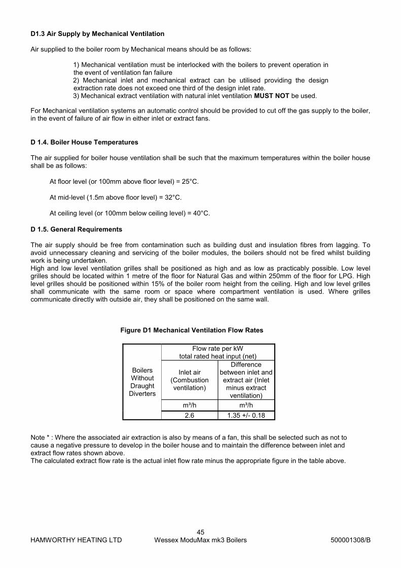
HAMWORTHY HEATING LTD
45 Wessex ModuMax mk3 Boilers
500001308/B
Figure D1 Mechanical Ventilation Flow Rates
Note * : Where the associated air extraction is also by means of a fan, this shall be selected such as not to cause a negative pressure to develop in the boiler house and to maintain the difference between inlet and extract flow rates shown above. The calculated extract flow rate is the actual inlet flow rate minus the appropriate figure in the table above.
D1.3 Air Supply by Mechanical Ventilation Air supplied to the boiler room by Mechanical means should be as follows:
1) Mechanical ventilation must be interlocked with the boilers to prevent operation in the event of ventilation fan failure 2) Mechanical inlet and mechanical extract can be utilised providing the design extraction rate does not exceed one third of the design inlet rate. 3) Mechanical extract ventilation with natural inlet ventilation MUST NOT be used.
For Mechanical ventilation systems an automatic control should be provided to cut off the gas supply to the boiler, in the event of failure of air flow in either inlet or extract fans.
D 1.4. Boiler House Temperatures
The air supplied for boiler house ventilation shall be such that the maximum temperatures within the boiler house shall be as follows:
At floor level (or 100mm above floor level) = 25°C.
At mid-level (1.5m above floor level) = 32°C.
At ceiling level (or 100mm below ceiling level) = 40°C.
D 1.5. General Requirements
The air supply should be free from contamination such as building dust and insulation fibres from lagging. To avoid unnecessary cleaning and servicing of the boiler modules, the boilers should not be fired whilst building work is being undertaken. High and low level ventilation grilles shall be positioned as high and as low as practicably possible. Low level grilles should be located within 1 metre of the floor for Natural Gas and within 250mm of the floor for LPG. High level grilles should be positioned within 15% of the boiler room height from the ceiling. High and low level grilles shall communicate with the same room or space where compartment ventilation is used. Where grilles communicate directly with outside air, they shall be positioned on the same wall.
Flow rate per kW total rated heat input (net)
Boilers Without Draught Diverters
Inlet air (Combustion ventilation)
Difference between inlet and extract air (Inlet minus extract
ventilation)
m³/h m³/h
2.6 1.35 +/- 0.18

HAMWORTHY HEATING LTD
46 Wessex ModuMax mk3 Boilers
500001308/B
APPENDIX E - WATER DATA
Model 97 /97
116/116
147/147 196/196
254/254
Water Connections (Flow & Return) G 1½” male G 2½” male
Maximum Water Pressure - bar g - (kPa) 10 (1000)
Water Content (litres) -excluding headers 16
16 22 22 22
System Design Flow Rate (litres/s) @ 11°C ΔT Rise 2.2
2.6 3.3 4.3 5.4
System Design Flow Rate (litres/s) @ 20°C ΔT Rise 1.2
1.4 1.8 2.4 3
System Design Flow Rate (litres/s) @ 30°C ΔT Rise 0.8 1.0 1.2 1.6 2.0
System Design Flow Rate (litres/s) @ 40°C ΔT Rise 0.6 0.7 0.9 1.2 1.5
Waterside Pressure Loss (mbar) @ 11°C ΔT Rise 61 91 500 850 1300
Waterside Pressure Loss (mbar) @ 20°C ΔT Rise 20 27 145 246 395
Waterside Pressure Loss (mbar) @ 30°C ΔT Rise 9 14 60 120 180
Waterside Pressure Loss (mbar) @ 40°C ΔT Rise 5 7 36 62 100
Minimum flow temperature setting
30°C @ 11°C ΔT 30°C @ 20°C ΔT 40°C @ 30°C ΔT 50°C @ 40°C ΔT
E1.1 Water Circulation System The Wessex ModuMax boiler has a low water content and the requirements of minimum water flow are given in the above table. Recommendations for the water circulation system are given in BS 6644 and CP 342. The following details are of particular importance for the correct installation of the water circulation system: 1) In a combined central heating and hot water system the hot water storage vessel must be of the indirect cylinder or calorifier type. The hot water storage vessel should be insulated, preferably with not less than 75mm (3”) thick mineral fibre, or its thermal equivalent. 2) Circulating pipework not forming part of the useful heating surface should be insulated to help prevent heat loss and possible freezing, particularly where pipes are run through roof spaces and ventilated cavities. Cisterns situated in areas which may be exposed to freezing conditions should also be insulated. Furthermore, insulation exposed to the weather should be rendered waterproof. 3) Drain valves must be located in accessible positions which permit the draining of the whole system, including the boiler and hot water storage vessel. 4) Each boiler module has G1½ or G2½ (refer to Table E1.1) male flow (indicated with a red spot) and return (indicated with a blue spot) connections. Boilers should be connected by flow and return headers. Headers should be connected to the system in a ‘reverse / return’ arrangement (the water flow in each header is in the same direction) to ensure equal flow in each module, or with a ‘single pipe header system’. Figure E1.1.1 on the following page show typical layouts. 5)Ideally, individual valves should be fitted to each module to enable isolation from the system, however, the arrangement must comply with the requirements of BS 6644.
Table E1.1—Water Data
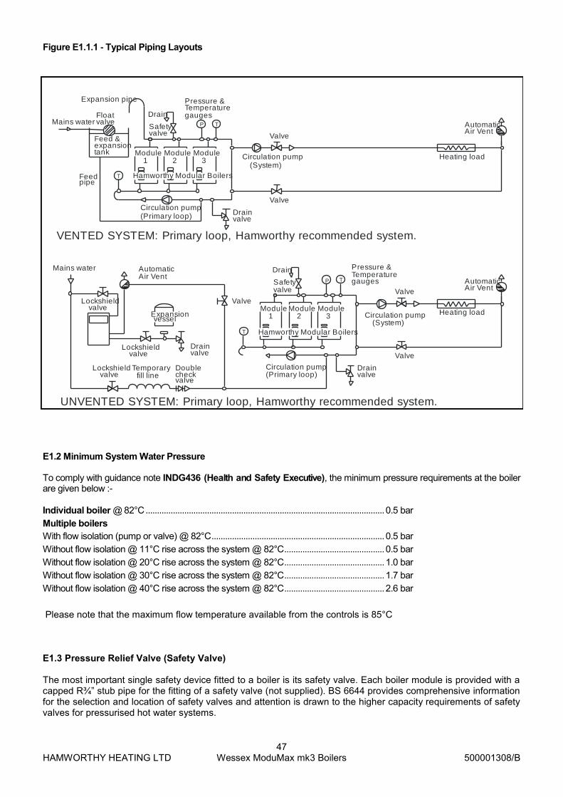
HAMWORTHY HEATING LTD
47 Wessex ModuMax mk3 Boilers
500001308/B
E1.2 Minimum System Water Pressure To comply with guidance note INDG436 (Health and Safety Executive), the minimum pressure requirements at the boiler are given below :-
Individual boiler @ 82°C ......................................................................................................... 0.5 bar
Multiple boilers
With flow isolation (pump or valve) @ 82°C ............................................................................ 0.5 bar
Without flow isolation @ 11°C rise across the system @ 82°C ............................................ 0.5 bar
Without flow isolation @ 20°C rise across the system @ 82°C ............................................ 1.0 bar
Without flow isolation @ 30°C rise across the system @ 82°C ............................................ 1.7 bar
Without flow isolation @ 40°C rise across the system @ 82°C ............................................ 2.6 bar
Please note that the maximum flow temperature available from the controls is 85°C E1.3 Pressure Relief Valve (Safety Valve) The most important single safety device fitted to a boiler is its safety valve. Each boiler module is provided with a capped R¾” stub pipe for the fitting of a safety valve (not supplied). BS 6644 provides comprehensive information for the selection and location of safety valves and attention is drawn to the higher capacity requirements of safety valves for pressurised hot water systems.
Figure E1.1.1 - Typical Piping Layouts
UNVENTED SYSTEM: Primary loop, Hamworthy recommended system.
VENTED SYSTEM: Primary loop, Hamworthy recommended system.
Circulation pump
valveDrain
Expansion pipe
Feedpipe
Mains water
Hamworthy Modular Boilers
Module
Safety
T
Feed &expansiontank
valve
Module1 2
valveFloat Drain
Valve
Module3
P
gauges
Pressure &Temperature
T
Circulation pump
Valve
(System)Heating load
AutomaticAir Vent
Valve
Air VentAutomatic
Valve
valveDrain
Valve
Module
Hamworthy Modular Boilers
Safety
T
valve
Module1 2
Drain
3Module
P gauges
Pressure &Temperature
T AutomaticAir Vent
Heating load
Lockshieldvalve fill line
Temporary Doublecheckvalve
vesselExpansion
valveLockshield
Mains water
valveDrain
valveLockshield
(Primary loop)
(System)Circulation pump
(Primary loop)Circulation pump

HAMWORTHY HEATING LTD
48 Wessex ModuMax mk3 Boilers
500001308/B
E1.4 Open Vent and Cold Feed Pipe.
Every boiler or group of boilers should have an open vent pipe and cold feed pipe installed between the boiler and the first water isolating valve. The minimum bore (mm) of these pipes per installation is shown in the table. The vent pipe must rise continually, any valve fitted between a boiler and the open vent pipe for maintenance purposes shall be of the 3 way type such that when closed to the vent pipe the boiler will be open to atmosphere. The vent pipe shall be protected against freezing where this might occur. See BS 6644 for detailed information on Open Vent and Cold Feed Pipes. E1.5 Altitude Gauge (Water Pressure Gauge)
Every boiler or group of boilers should be provided with an altitude gauge complete with isolating valve. See Figure E1.1.1 for typical position. E1.6 Thermometer
A thermometer complete with pocket should be fitted in the pipework to indicate water flow temperature. See Figure E1.1.1 for typical position. E1.7 Drain Valves
Each boiler should have a 15mm NB drain valve (not Hamworthy Heating Ltd supply) fitted in the boiler return to drain the boiler only. The heating system in total should have drain valves as recommended by BS 6644. See Figure E1.1.1 for typical position. E1.8 Circulating Pump
One or more circulating pumps will be required to circulate water around the boilers and heating system. The pump should be sited to facilitate servicing. It is important that when Wessex ModuMax boilers are used to replace boilers on an existing system, the pumps should be checked for performance against the new boiler waterside pressure loss to ensure that the minimum flow rate can be obtained. It is also important that the existing system be flushed through twice to remove any loose matter which may have accumulated. If in any doubt regarding the cleanliness of the system, a coarse filter should be fitted in the return pipework to the boilers.
If boilers are run off time clock control a pump overrun (not Hamworthy Heating Ltd supply) should be fitted which must run for a minimum of 5 minutes on shutdown of the last boiler. This must be interlocked to the LMS for frost protection. E1.9 Minimum Water Flow Rates
Minimum water flow rates are shown in table at beginning of Appendix E. These flow rates should be maintained through the boiler at all times whilst the boiler is firing. If the water flow rate is allowed to fall below the minimum the boiler heat exchanger could fail due to the resultant scale formation. Particular attention should be paid to the restriction of external flow circuits during periods of low heat demand. E1.10 Waterside Pressure Drop The waterside hydraulic resistance (Pressure drop) is given in table at beginning of Appendix E. E1.11 Water Flow Controls
Any external mixing valve / shunt pump or similar controls MUST always ensure that the minimum water flow rate as given in table at beginning of Appendix E is maintained. If there is any doubt relating to site flow conditions it is suggested that a flow switch is fitted. The flow switch should be connected such that the boiler will shut down if insufficient flow occurs. E1.12 Frost Protection Consideration should be given to fitting a frost thermostat set at approximately 4°C.
Boiler Output Feed mm Vent mm
60 - 150kW 25 32
150 - 300 kW 32 38
300 - 600 kW 38 50
>601 KW 50 65
Figure E1.3 Cold Feed and Vent Pipe Sizes

HAMWORTHY HEATING LTD
49 Wessex ModuMax mk3 Boilers
500001308/B
E1.13 Unvented Systems
Refer to Figure E1.1.1 on opposite page for typical layout of an unvented (Pressurised) Hot Water System. For system design refer to BS 7074 Part 2. In order to correctly size a pressurisation unit for any heating system the following parameters are required.
1) Static height of highest component in system (metres) 2) System volume. If this is not known, a general rule of thumb of 10litres/kW of installed boiler power
can be used. 3) Maximum flow temperature (°C) 4) Maximum system hot working pressure, generally given in bar gauge.
From the parameters given, Hamworthy Heating can size the pressurisation unit and also the expansion vessel required.
Care must be taken in sizing expansion vessels to ensure maximum acceptance factors are not exceeded. Normally manufacturers of vessels impose a limit of 0.5. This value must not be exceeded at any time during the operation of the boiler, this includes the over pressure condition should a safety valve lift.
Consideration should also be given to sizing of the safety valve(s) in the system. Refer to BS 6759: Part 1 for further information and to BS 6880: Part 1 for design considerations.

HAMWORTHY HEATING LTD
50 Wessex ModuMax mk3 Boilers
500001308/B
Figure E 1.3.1 - Schematic 1 - External Time Clock Enabled Boiler
Hydraulic Schemes: For Single Boiler Installations
Figure E 1.3.2 - Schematic 2 - Two Heating Circuits with DHW & Boiler Shunt Pump
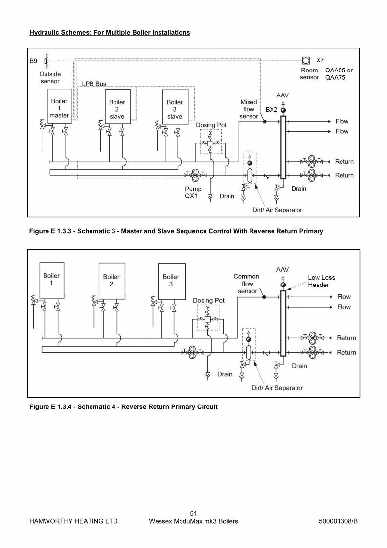
HAMWORTHY HEATING LTD
51 Wessex ModuMax mk3 Boilers
500001308/B
Figure E 1.3.3 - Schematic 3 - Master and Slave Sequence Control With Reverse Return Primary
Hydraulic Schemes: For Multiple Boiler Installations
Figure E 1.3.4 - Schematic 4 - Reverse Return Primary Circuit

HAMWORTHY HEATING LTD
52 Wessex ModuMax mk3 Boilers
500001308/B
Figure E 1.3.5 - Schematic 5 - Primary Circuit With Individual Boiler Shunt Pumps
Hydraulic Schemes:
Figure E 1.3.6 - Schematic 6 - Reverse Return Primary Circuit with Individual Motorised Boiler Isolation
Note: Motorised valves can be either power open/power close or power open/spring return close.
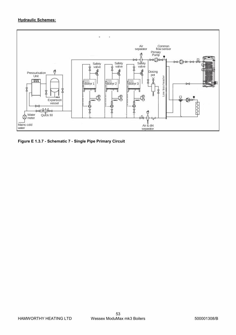
HAMWORTHY HEATING LTD
53 Wessex ModuMax mk3 Boilers
500001308/B
Hydraulic Schemes:
Figure E 1.3.7 - Schematic 7 - Single Pipe Primary Circuit
Watermeter
Mains cold water
Quick fill
Safetyvalve
Safetyvalve
Safetyvalve
Air separator
Commonflow sensor
PrimaryPump
Dosing pot
Lo
w lo
ss
he
ad
er
Expansion vessel
PressurisationUnit
Boiler 1 Boiler 2 Boiler 3
Air & dirtseparator
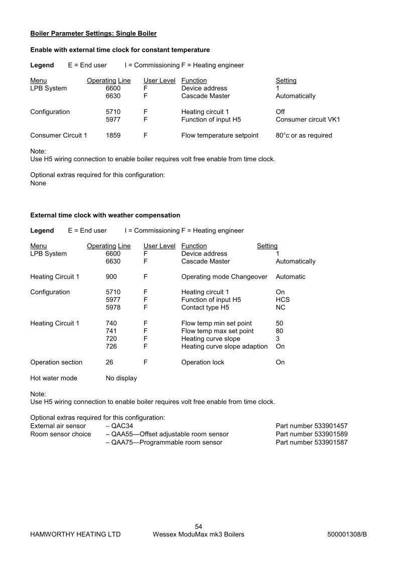
HAMWORTHY HEATING LTD
54 Wessex ModuMax mk3 Boilers
500001308/B
Enable with external time clock for constant temperature Legend E = End user I = Commissioning F = Heating engineer Menu Operating Line User Level Function Setting LPB System 6600 F Device address 1 6630 F Cascade Master Automatically
Configuration 5710 F Heating circuit 1 Off 5977 F Function of input H5 Consumer circuit VK1
Consumer Circuit 1 1859 F Flow temperature setpoint 80°c or as required
Note: Use H5 wiring connection to enable boiler requires volt free enable from time clock.
Optional extras required for this configuration:
None
Boiler Parameter Settings: Single Boiler
External time clock with weather compensation Legend E = End user I = Commissioning F = Heating engineer Menu Operating Line User Level Function Setting LPB System 6600 F Device address 1 6630 F Cascade Master Automatically Heating Circuit 1 900 F Operating mode Changeover Automatic Configuration 5710 F Heating circuit 1 On 5977 F Function of input H5 HCS 5978 F Contact type H5 NC
Heating Circuit 1 740 F Flow temp min set point 50 741 F Flow temp max set point 80 720 F Heating curve slope 3 726 F Heating curve slope adaption On
Operation section 26 F Operation lock On
Hot water mode No display
Note: Use H5 wiring connection to enable boiler requires volt free enable from time clock.
Optional extras required for this configuration:
External air sensor – QAC34 Part number 533901457
Room sensor choice – QAA55—Offset adjustable room sensor Part number 533901589
– QAA75—Programmable room sensor Part number 533901587

HAMWORTHY HEATING LTD
55 Wessex ModuMax mk3 Boilers
500001308/B
Internal time clock with two heating circuits, DHW & boiler shunt pump Legend E = End user I = Commissioning F = Heating engineer Menu Operating Line User Level Function Setting Configuration 5890 F Relay output QX1 Boiler pump Q1 5931 F Sensor input BX2 Common flow Sensor B10 5977 F Function input H5 None 5710 F Heating Circuit 1 On 5715 F Heating Circuit 2 On 6021 F Function extension Module 2 Heating Circuit 1 6022 F Function extension Module 3 Heating Circuit 2 6054 F Function input H2 Module 2 Room Stat HC1 6062 F Function input H2 Module 3 Room Stat HC2 Domestic Hot Water 1610 F Nominal Set Point 60°C Domestic Hot Water - additional parameters may need to change Extension module AGU 2.550A109 are require for each addition heating circuit to be controlled. Maximum of three additional extension modules can be accommodated per boiler. Heating mode Auto symbol Hot water mode On Note: For this application, the Function extension modules 2 & 3, with respect to their parameter setting as heating cir-cuits 1 & 2, have pre-defined outputs for each extension module as shown in the table below.
Boiler Parameter Settings: Single Boiler
Note: To check operation of pumps, mixing valves & thermostats select: engineer – diagnostic consumers – parameters 8730 to 8779 Optional extras required for this configuration:
2x Heating circuit extension modules AGU2.55A109 Part number 563605669
Heating sensor kit – QA236 Part number 563605673
2x Room sensor choice – QAA55—Offset adjustable room sensor Part number 533901589
– QAA75—Programmable room sensor Part number 533901587
DHW sensor kit – QA236 Part number 563605674
Connections on heating circuit extension module AGU2.55A109:
QX21—Switched live—Mixing valve opening
QX22—Switched live—Mixing valve closing
QX23—Switched live—Heating circuit pump (Contactor required for pump)
BX21—Flow temperature sensor—Heating circuit
H2—Heating circuit room thermostat—Basic type no/nc switch vfc (Only use if optional room sensor QAA55 or
QAA75 are not specified)
Wiring connections on heating circuit extension module AGU 2.550A109
QX21 QX22 QX23 BX21 BX22 H2
Multifunctional * * * * * *
Heating circuit 1 Y1 Y2 Q2 B1 * *
Heating circuit 2 Y5 Y6 Q6 B12 * *
Heating circuit 3 Y11 Y12 Q20 B14 * *
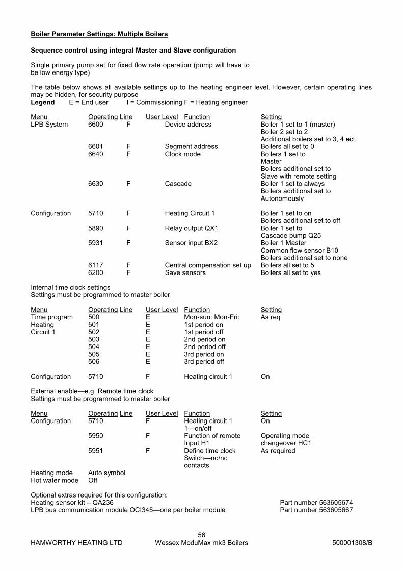
HAMWORTHY HEATING LTD
56 Wessex ModuMax mk3 Boilers
500001308/B
Sequence control using integral Master and Slave configuration Single primary pump set for fixed flow rate operation (pump will have to be low energy type)
The table below shows all available settings up to the heating engineer level. However, certain operating lines may be hidden, for security purpose Legend E = End user I = Commissioning F = Heating engineer Menu Operating Line User Level Function Setting LPB System 6600 F Device address Boiler 1 set to 1 (master) Boiler 2 set to 2 Additional boilers set to 3, 4 ect. 6601 F Segment address Boilers all set to 0 6640 F Clock mode Boilers 1 set to Master Boilers additional set to Slave with remote setting 6630 F Cascade Boiler 1 set to always Boilers additional set to Autonomously Configuration 5710 F Heating Circuit 1 Boiler 1 set to on Boilers additional set to off 5890 F Relay output QX1 Boiler 1 set to Cascade pump Q25 5931 F Sensor input BX2 Boiler 1 Master Common flow sensor B10 Boilers additional set to none 6117 F Central compensation set up Boilers all set to 5 6200 F Save sensors Boilers all set to yes Internal time clock settings Settings must be programmed to master boiler Menu Operating Line User Level Function Setting Time program 500 E Mon-sun: Mon-Fri: As req Heating 501 E 1st period on Circuit 1 502 E 1st period off 503 E 2nd period on 504 E 2nd period off 505 E 3rd period on 506 E 3rd period off Configuration 5710 F Heating circuit 1 On External enable—e.g. Remote time clock Settings must be programmed to master boiler Menu Operating Line User Level Function Setting Configuration 5710 F Heating circuit 1 On 1—on/off 5950 F Function of remote Operating mode Input H1 changeover HC1 5951 F Define time clock As required Switch—no/nc contacts Heating mode Auto symbol Hot water mode Off Optional extras required for this configuration: Heating sensor kit – QA236 Part number 563605674 LPB bus communication module OCI345—one per boiler module Part number 563605667
Boiler Parameter Settings: Multiple Boilers

HAMWORTHY HEATING LTD
57 Wessex ModuMax mk3 Boilers
500001308/B
Individual boilers enabled from B.M.S. using 0-10V analogue input Legend E = End user I = Commissioning F = Heating engineer Navistem settings BMS 0-10v Power Control Menu Operating Line User Level Function Setting LPB System 6600 F Device address 1 Configuration 5710 F Heating circuit 1 Off 5950 F Function input H1 Output req VK1 10v 5951 F Contact type H1 NO 5953 F Voltage value H1 0.1v 5954 F Function value 1 H1 200 (200 = 20% modulation) 5955 F Voltage value 2 H1 10.0v 5956 F Function valve 2 H1 1000 (1000 = 100% modulation)
5890 F Relay output QX1 Boiler pump Q1
BMS 0-10v Temperature Menu Operating Line User Level Function Setting LPB System 6600 F Device address 1 Configuration 5710 F Heating circuit 1 Off 5950 F Function input H1 Consumer req VK1 10v 5951 F Contact type H1 NO 5953 F Voltage value H1 0.5v 5954 F Function value 1 H1 0 (0 = 0°C) 5955 F Voltage value 2 H1 10.0v 5956 F Function valve 2 H1 800 (800 = 80°C)
5890 F Relay output QX1 Boiler pump Q1
Note: Use H1 wiring connection for 0-10V analog input from B.M.S. Optional extras required for this configuration:
None
Boiler Parameter Settings: Multiple Boilers

HAMWORTHY HEATING LTD
58 Wessex ModuMax mk3 Boilers
500001308/B
Legend E = End user I = Commissioning F = Heating engineer Menu Operating Line User Level Function Setting Configuration 5892 F Relay output QX3 Boiler pump Q1 Note: The QX3 terminals have live outputs on NO & NC connection together with neutral & earth this will facilitate pow-ering the valve open and closed. Optional extras required for this configuration:
None
Boiler Parameter Settings: Individual Boiler Flow Isolation Using Motorised Valve
The maximum number of boiler modules that can be controlled from Merley boiler sequence controller is 16. The table below shows all available settings up to the heating engineer level. However, certain operating lines may be hidden, for security purposes Legend E = End user I = Commissioning F = Heating engineer Menu Operating Line User Level Function Setting LPB System 6600 F Device address Boiler 1 set to 2 Boiler 2 set to 3 Additional boilers set to 4, 5 ect. 6601 F Segment address Boilers all set to 0 6640 F Clock mode Boilers all set to Slave with remote setting Configuration 5710 F Heating Circuit 1 Boilers all set to off 6200 F Save sensors Boilers all yes 6117 F Central compensation set up Boilers all set to 5 Note: Merley to be set up independently using the Merley O&M (500001210) Optional extras required for this configuration:
Merley wall mounted boiler sequence controller Part number 563605672
Merley loose boiler sequence controller for panel mounting Part number 563605671
LPB bus communication module OCI345—one per boiler module Part number 563605667 Note: 2x LPB bus communications modules are supplied with each Merley boiler sequence controller, therefore addi-tional modules are only required for boiler module 3 upwards.
Boiler Parameter Settings: Multiple Boilers With External Merley Boiler Sequence Controller
Legend E = End user I = Commissioning F = Heating engineer Menu Operating Line User Level Function Setting Configuration 5890 F Relay output QX1 Boiler pump Q1 Optional extras required for this configuration:
None
Boiler Parameter Settings: Individual Boiler Shunt Pumps

HAMWORTHY HEATING LTD
59 Wessex ModuMax mk3 Boilers
500001308/B
HAMWORTHY HEATING LTD
60 Wessex ModuMax mk3 Boilers
500001308/B
INSTALLER SITE ADDRESS
BOILER TYPE BOILER SIZE(S) UNIT NO(S). SERIAL NO(S). FLUE
USEFUL USER INFORMATION


Hamworthy Heating Accredited Agents
Customer Service Centre
Hamworthy Heating Limited,
Fleets Corner, Poole,
Dorset BH17 0HH
Telephone: 0845 450 2866
Fax: 01202 662522
Email: [email protected]
Website: www.hamworthy-heating.com
Hamworthy reserves the right to make changes and improvements which may necessitate alteration to the specification without prior notice.
North West England (Sales & Service)
Gillies Modular Services
210-218 New Chester Road, Birkenhead, Merseyside L41 9BG
tel: 0151 666 1030 fax: 0151 647 8101
Southern Ireland (Sales & Service)
HEVAC Limited
Naas Road, Dublin 12, Ireland
tel: 00 353 141 91919 fax: 00 353 145 84806
Northern Ireland (Sales & Service)
HVAC Supplies Limited
Unit A6, Dargan Court, Dargan Crescent, Belfast BT3 9JP
tel: 02890 747737 fax: 02890 741233
Scotland (Sales & Service)
McDowall Modular Services
2 Penston Road, Glasgow, Scotland G33 4AG
tel: 0141 336 8795 fax: 0141 771 9635
North East England (Service)
Allison Heating Products
12 Sunnyside Lane, Cleadon Village, Sunderland SR6 7XB
tel: 0191 536 8833 fax: 0191 536 9933
Hamworthy Heating Customer Service Centre
Sales
tel: 0845 450 2865
Technical Enquiries
tel: 0845 450 2865
Servicing
tel: 01202 662555
Spares
tel: 0845 450 2866


