Workshop on Picosecond Photon SensorsLaboratoire de Physique Corpusculaire de Clermont
Clermont-Ferrand, [email protected] 1
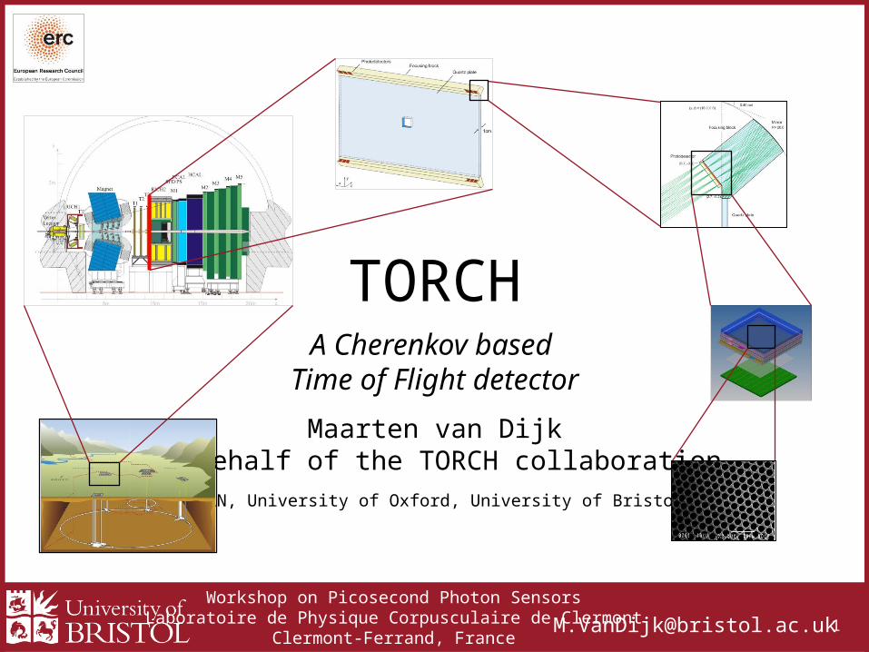
TORCH
Maarten van DijkOn behalf of the TORCH collaboration
(CERN, University of Oxford, University of Bristol)
A Cherenkov based Time of Flight detector
Workshop on Picosecond Photon SensorsLaboratoire de Physique Corpusculaire de Clermont
Clermont-Ferrand, [email protected] 2
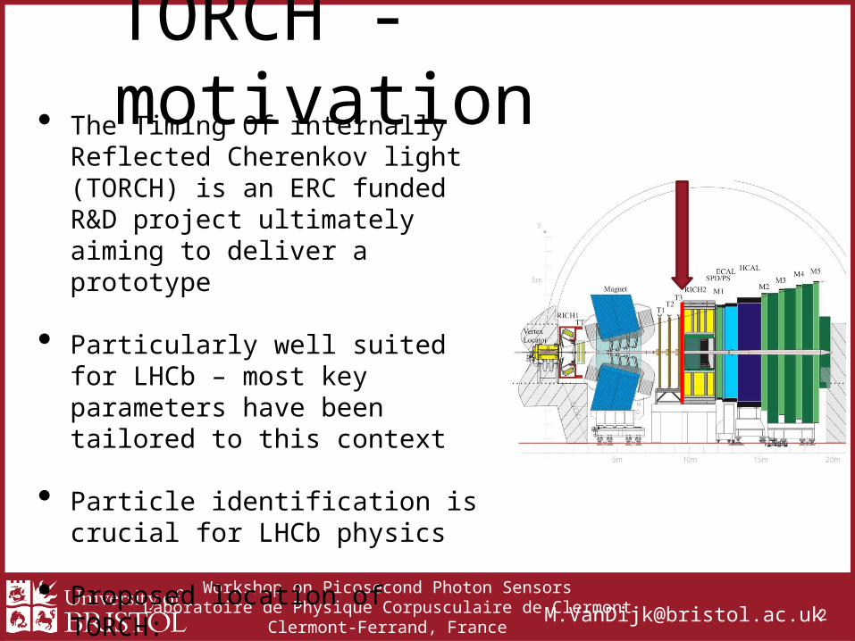
TORCH - motivation• The Timing Of internally Reflected
Cherenkov light (TORCH) is an ERC funded R&D project ultimately aiming to deliver a prototype
• Particularly well suited for LHCb – most key parameters have been tailored to this context
• Particle identification is crucial for LHCb physics
• Proposed location of TORCH: in front of RICH2

Workshop on Picosecond Photon SensorsLaboratoire de Physique Corpusculaire de Clermont
Clermont-Ferrand, [email protected] 3
Goals• Particle ID is achieved in TORCH
through measuring time of flight (TOF) of charged particles
• Goal • To provide 3σ K-π separation for
momentum range 2-10 GeV/c(up to kaon threshold of RICH1)
• Requirement• TOF difference between K-π is 37.5ps at
10 GeV/c at 9.5m• Required per-track time resolution set at 10-
15psTime of flight difference of pions vs kaons plotted against momentum
Theoretical K-π separation (Nσ) for TORCH as a function of momentum
Workshop on Picosecond Photon SensorsLaboratoire de Physique Corpusculaire de Clermont
Clermont-Ferrand, [email protected] 4
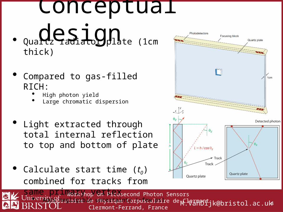
Conceptual design• Quartz radiator plate (1cm thick)
• Compared to gas-filled RICH:• High photon yield • Large chromatic dispersion
• Light extracted through total internal reflection to top and bottom of plate
• Calculate start time (t0) combined for tracks from same primary vertex
• Adds negligible uncertainty (~few ps)
• Timing of Cherenkov photons used to calculate time of arrival of signal track at plate
Workshop on Picosecond Photon SensorsLaboratoire de Physique Corpusculaire de Clermont
Clermont-Ferrand, [email protected] 5
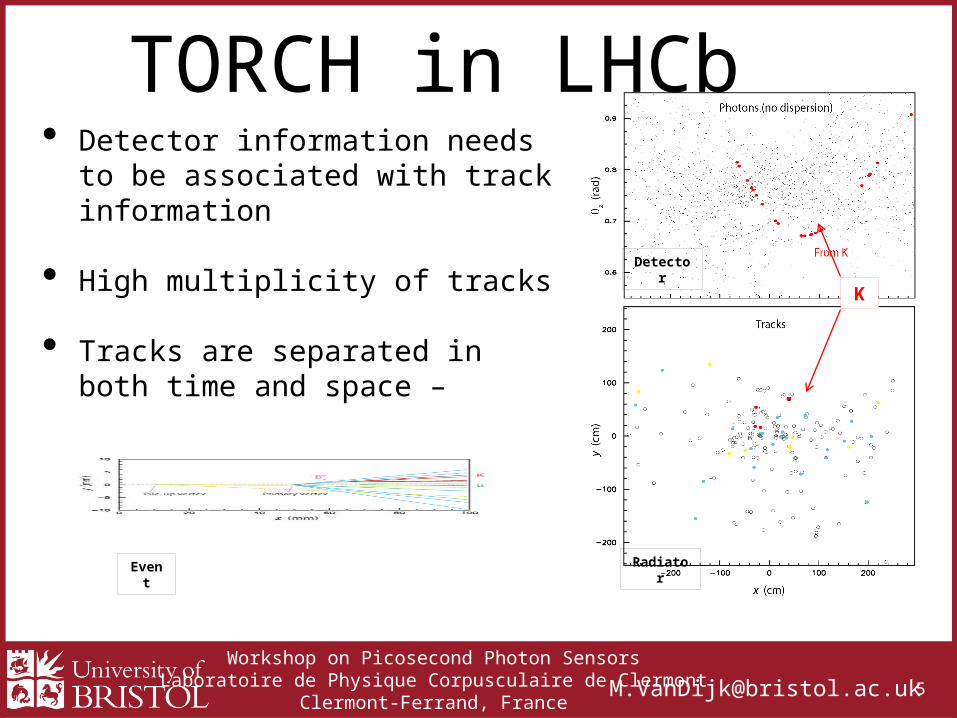
Radiator
Detector
TORCH in LHCb• Detector information needs to be
associated with track information
• High multiplicity of tracks
• Tracks are separated in both time and space – essential for pattern recognition
Event
K
Workshop on Picosecond Photon SensorsLaboratoire de Physique Corpusculaire de Clermont
Clermont-Ferrand, [email protected] 6
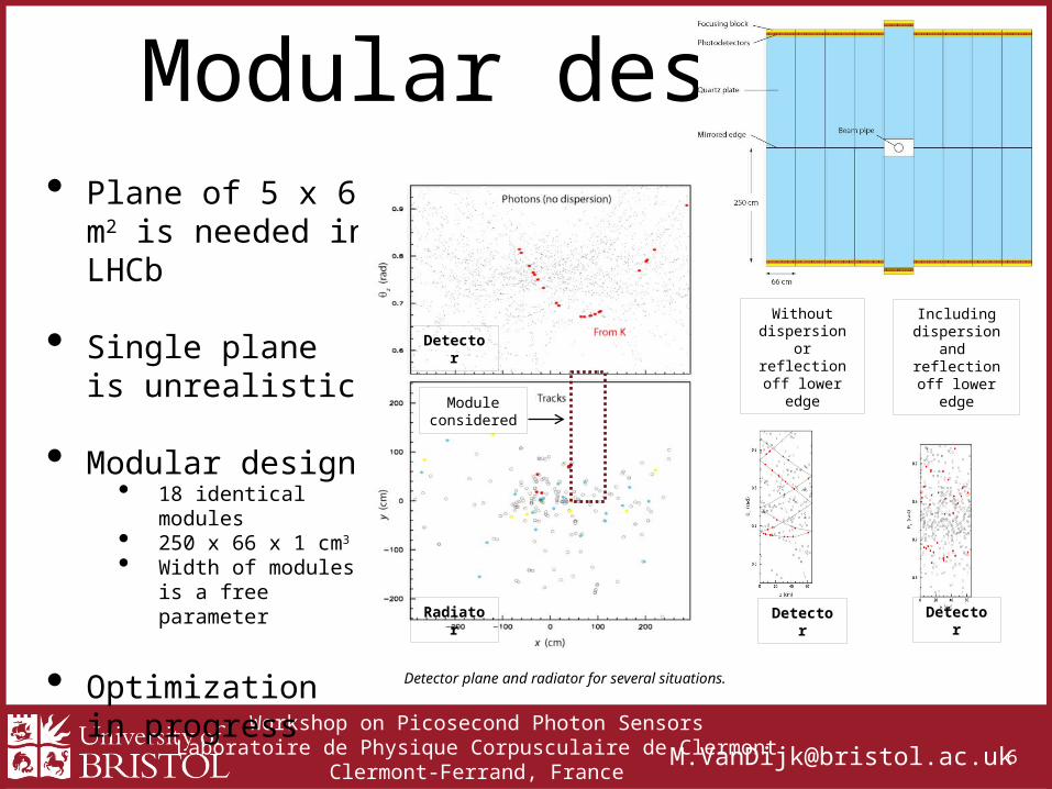
Modular design• Plane of 5 x 6 m2 is
needed in LHCb
• Single plane is unrealistic
• Modular design• 18 identical modules• 250 x 66 x 1 cm3
• Width of modules is a free parameter
• Optimization in progress
Without dispersion orreflection off lower edge
Including dispersion and
reflection off lower edge
Moduleconsidered
Radiator
Detector
Detector Detector
Detector plane and radiator for several situations.
Workshop on Picosecond Photon SensorsLaboratoire de Physique Corpusculaire de Clermont
Clermont-Ferrand, [email protected] 7
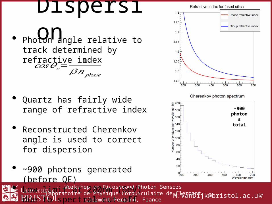
Dispersion• Photon angle relative to track
determined by refractive index
• Quartz has fairly wide range of refractive index
• Reconstructed Cherenkov angle is used to correct for dispersion
• ~900 photons generated (before QE)• Low limit at 200nm (6eV) due to
spectral cut-off due to radiator
𝑐𝑜𝑠𝜃𝑐=1
𝛽𝑛 h𝑝 𝑎𝑠𝑒
~900 photons
total
Workshop on Picosecond Photon SensorsLaboratoire de Physique Corpusculaire de Clermont
Clermont-Ferrand, [email protected] 8
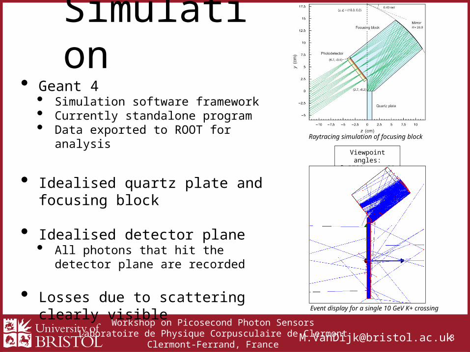
Simulation• Geant 4
• Simulation software framework• Currently standalone program• Data exported to ROOT for analysis
• Idealised quartz plate and focusing block
• Idealised detector plane• All photons that hit the detector plane are
recorded
• Losses due to scattering clearly visible
Viewpoint angles:θ=270° φ=0°
Event display for a single 10 GeV K+ crossing
Raytracing simulation of focusing block
Workshop on Picosecond Photon SensorsLaboratoire de Physique Corpusculaire de Clermont
Clermont-Ferrand, [email protected] 9
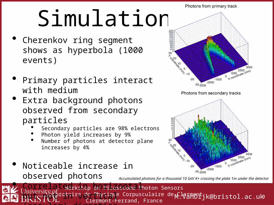
Simulation• Cherenkov ring segment shows as
hyperbola (1000 events)
• Primary particles interact with medium• Extra background photons observed
from secondary particles• Secondary particles are 98% electrons• Photon yield increases by 9%• Number of photons at detector plane increases by 4%
• Noticeable increase in observed photons• Correlated in horizontal but not in
vertical (angular) direction
• Simulation studies ongoingAccumulated photons for a thousand 10 GeV K+ crossing the plate 1m under the detector
Workshop on Picosecond Photon SensorsLaboratoire de Physique Corpusculaire de Clermont
Clermont-Ferrand, [email protected] 1
0
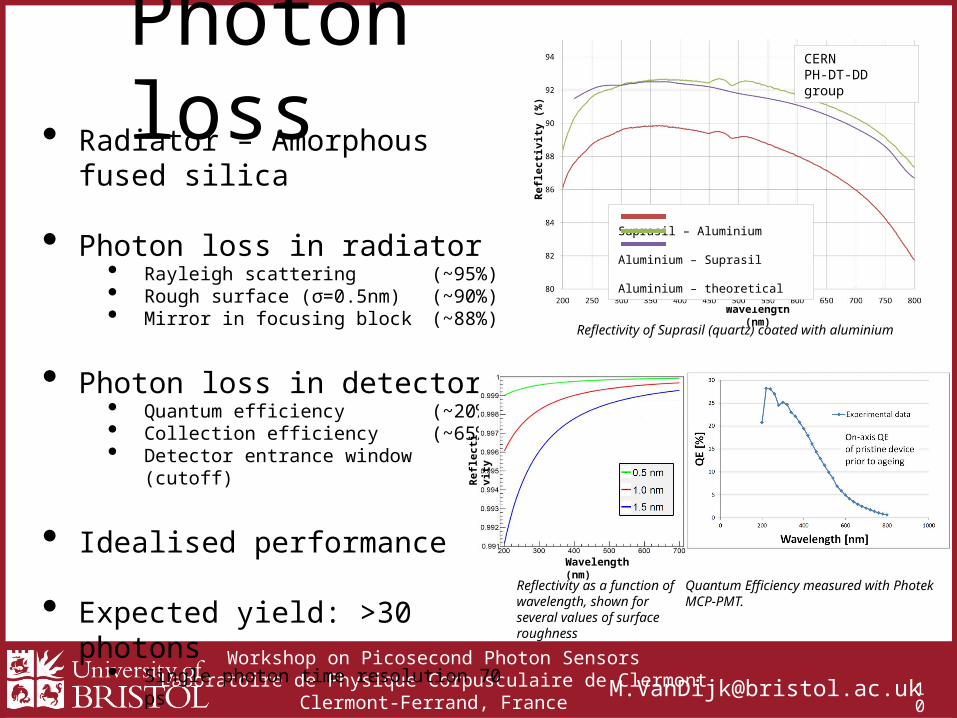
Photon loss• Radiator – Amorphous fused silica
• Photon loss in radiator• Rayleigh scattering (~95%)• Rough surface (σ=0.5nm) (~90%)• Mirror in focusing block (~88%)
• Photon loss in detector• Quantum efficiency (~20%)• Collection efficiency (~65%)• Detector entrance window (cutoff)
• Idealised performance
• Expected yield: >30 photons• Single photon time resolution 70 ps
Reflectivity of Suprasil (quartz) coated with aluminium
Quantum Efficiency measured with Photek MCP-PMT.
Reflectivity as a function of wavelength, shown for several values of surface roughness
Wavelength (nm)
Refle
ctivi
ty
Wavelength (nm)
Refle
ctivi
ty (%
)
Suprasil – Aluminium Aluminium – Suprasil Aluminium – theoretical
CERN PH-DT-DD group
Workshop on Picosecond Photon SensorsLaboratoire de Physique Corpusculaire de Clermont
Clermont-Ferrand, [email protected] 1
1
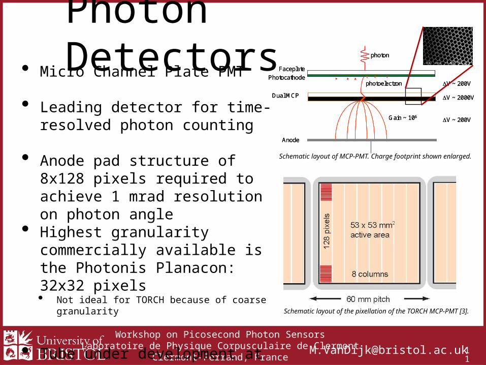
Photon Detectors• Micro Channel Plate PMT
• Leading detector for time-resolved photon counting
• Anode pad structure of 8x128 pixels required to achieve 1 mrad resolution on photon angle
• Highest granularity commercially available is the Photonis Planacon: 32x32 pixels• Not ideal for TORCH because of coarse granularity
• Tube under development at industrial partner (Photek Ltd, UK)
Faceplate
Photocathode
Dual MCP
Anode
Gain ~ 106
photoelectron V ~ 200V
V ~ 200V
V ~ 2000V
photon
Faceplate
Photocathode
Dual MCP
Anode
Gain ~ 106
photoelectron V ~ 200V
V ~ 200V
V ~ 2000V
photon
Schematic layout of MCP-PMT. Charge footprint shown enlarged.
Schematic layout of the pixellation of the TORCH MCP-PMT [3].
Workshop on Picosecond Photon SensorsLaboratoire de Physique Corpusculaire de Clermont
Clermont-Ferrand, [email protected] 1
2
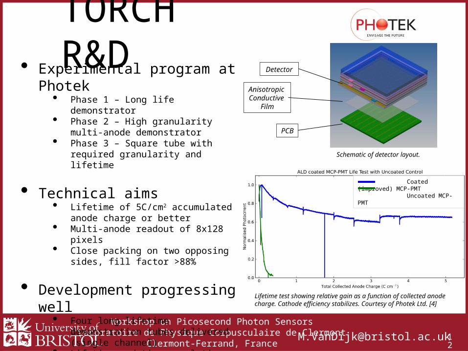
TORCH R&D• Experimental program at Photek
• Phase 1 – Long life demonstrator• Phase 2 – High granularity multi-anode
demonstrator• Phase 3 – Square tube with required
granularity and lifetime
• Technical aims• Lifetime of 5C/cm2 accumulated anode
charge or better• Multi-anode readout of 8x128 pixels• Close packing on two opposing sides, fill
factor >88%
• Development progressing well• Four long-lifetime demonstration tubes
delivered (single channel)• Lifetime and time resolution tests currently
underway
• More details in talk by J. Milnes • Wednesday 16:00-16:25
Detector
Anisotropic Conductive
Film
PCB
Lifetime test showing relative gain as a function of collected anode charge. Cathode efficiency stabilizes. Courtesy of Photek Ltd. [4]
Schematic of detector layout.
Coated (improved) MCP-PMT Uncoated MCP-PMT
Workshop on Picosecond Photon SensorsLaboratoire de Physique Corpusculaire de Clermont
Clermont-Ferrand, [email protected] 1
3
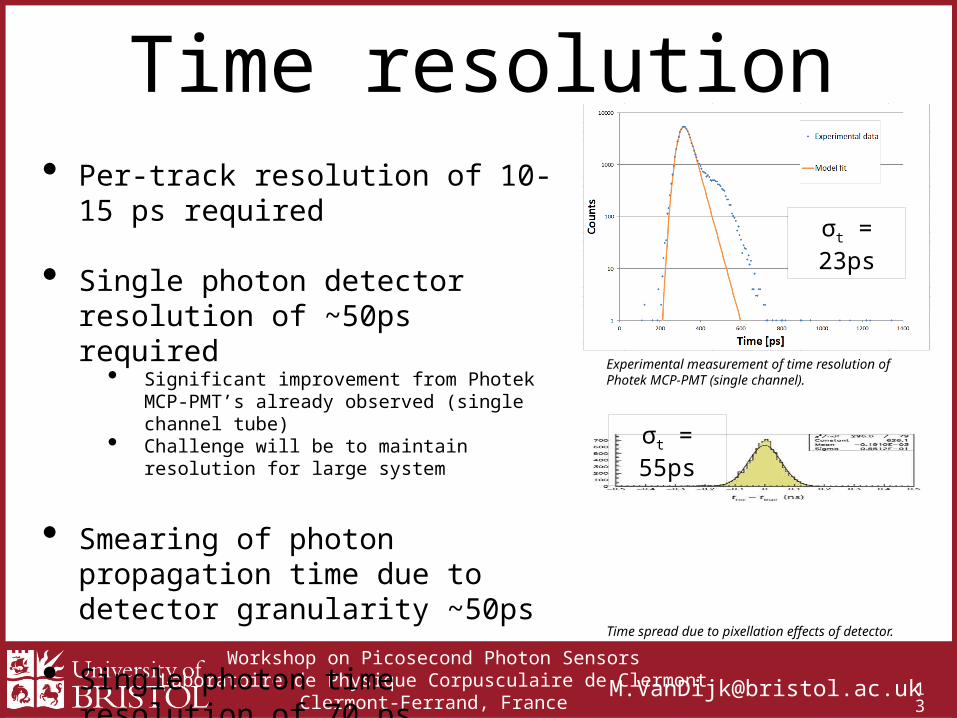
Time resolution• Per-track resolution of 10-15 ps required
• Single photon detector resolution of ~50ps required
• Significant improvement from Photek MCP-PMT’s already observed (single channel tube)
• Challenge will be to maintain resolution for large system
• Smearing of photon propagation time due to detector granularity ~50ps
• Single photon time resolution of 70 ps achievable
σt = 55ps
Time spread due to pixellation effects of detector.
Experimental measurement of time resolution of Photek MCP-PMT (single channel).
σt = 23ps
Workshop on Picosecond Photon SensorsLaboratoire de Physique Corpusculaire de Clermont
Clermont-Ferrand, [email protected] 1
4
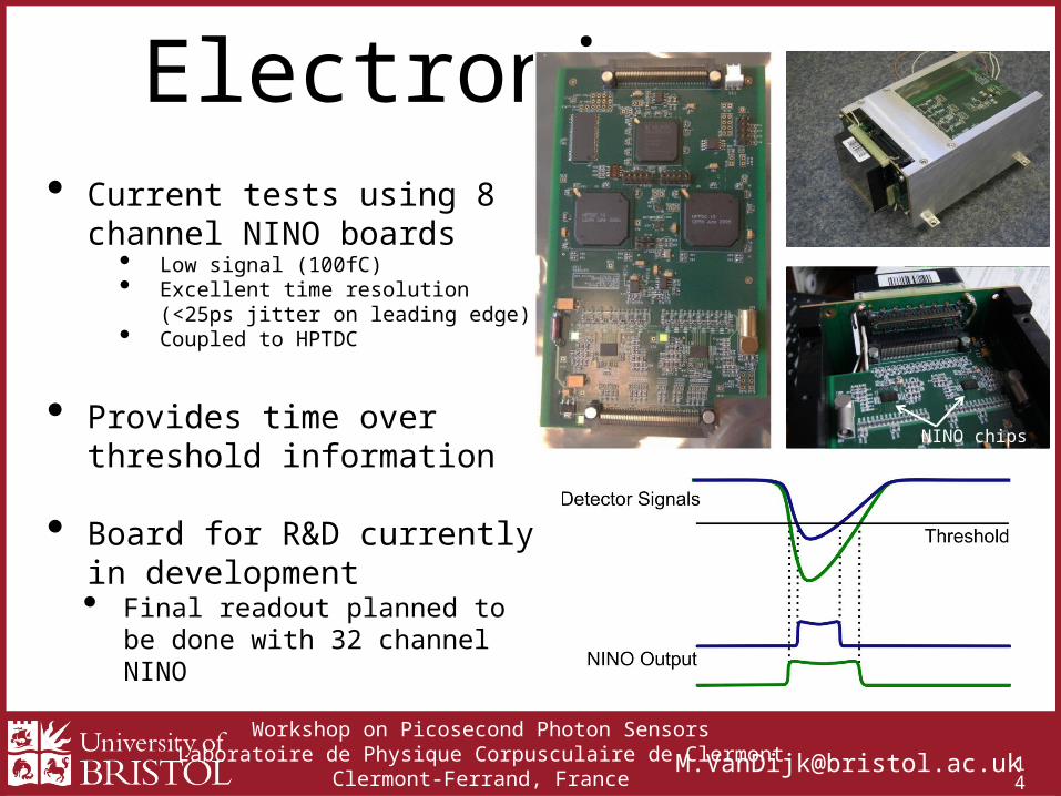
Electronics• Current tests using 8 channel
NINO boards• Low signal (100fC)• Excellent time resolution
(<25ps jitter on leading edge)• Coupled to HPTDC
• Provides time over threshold information
• Board for R&D currently in development• Final readout planned to be done with
32 channel NINO
NINO chips
Workshop on Picosecond Photon SensorsLaboratoire de Physique Corpusculaire de Clermont
Clermont-Ferrand, [email protected] 1
5
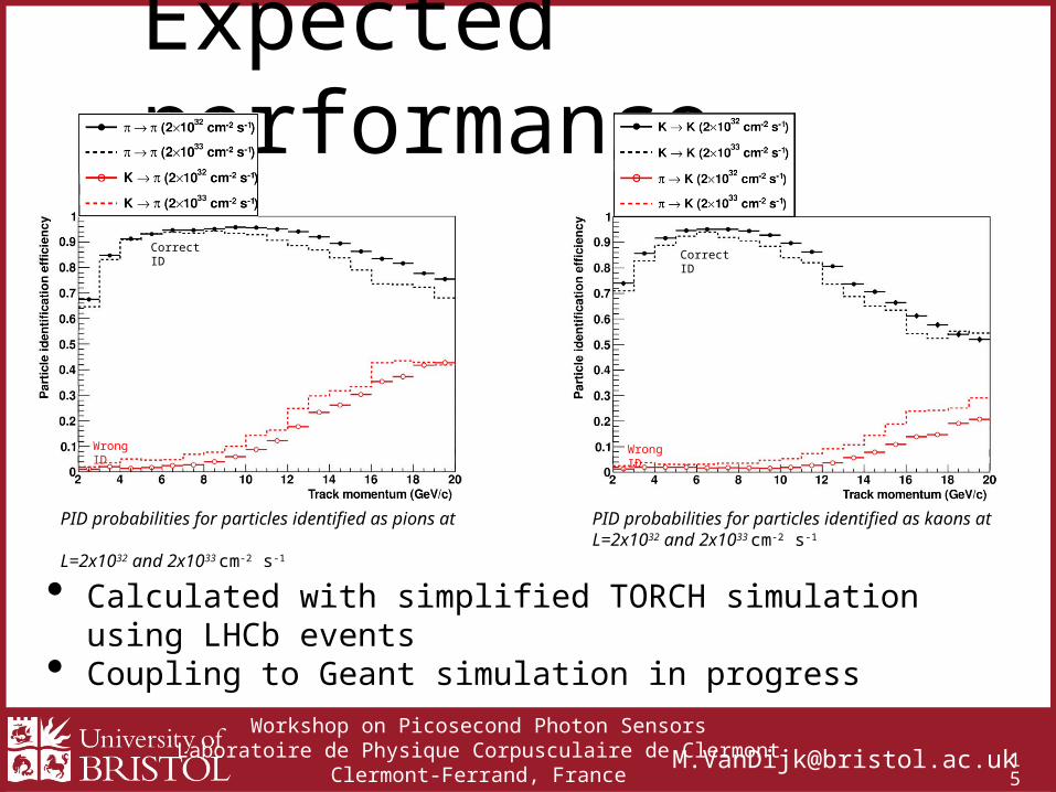
Expected performance
PID probabilities for particles identified as pions at L=2x1032 and 2x1033 cm-2 s-1
PID probabilities for particles identified as kaons at L=2x1032 and 2x1033 cm-2 s-1
Correct ID
Wrong ID
Correct ID
Wrong ID
• Calculated with simplified TORCH simulation using LHCb events• Coupling to Geant simulation in progress
Workshop on Picosecond Photon SensorsLaboratoire de Physique Corpusculaire de Clermont
Clermont-Ferrand, [email protected] 1
6
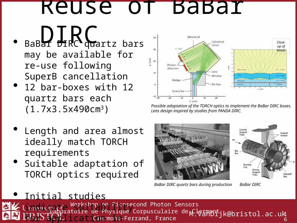
Reuse of BaBar DIRC• BaBar DIRC quartz bars may be
available for re-use following SuperB cancellation
• 12 bar-boxes with 12 quartz bars each (1.7x3.5x490cm3)
• Length and area almost ideally match TORCH requirements
• Suitable adaptation of TORCH optics required
• Initial studies indicate suitability for application in TORCH
• Studies ongoing
Close-up of lenses
Possible adaptation of the TORCH optics to implement the BaBar DIRC boxes.Lens design inspired by studies from PANDA DIRC.
BaBar DIRC quartz bars during production BaBar DIRC
Workshop on Picosecond Photon SensorsLaboratoire de Physique Corpusculaire de Clermont
Clermont-Ferrand, [email protected] 1
7
Conclusions• TORCH is a novel concept to achieve high precision Time-Of-Flight over
large area for particle identification using Cherenkov light
• Proposed for the LHCb upgrade to complement current particle ID provided by the RICH system, specifically at 2-10 GeV/c momentum
• Target resolution for single photons (<70ps) to give required per-track time resolution of 10-15ps for 3σ pion-kaon separation up to 10 GeV/c
• R&D programme currently ongoing• Long lifetime tubes have been delivered and are currently undergoing testing• Design of next phase is going according to plan
• Proposal for reuse of BaBar DIRC quartz bar has been submitted
Workshop on Picosecond Photon SensorsLaboratoire de Physique Corpusculaire de Clermont
Clermont-Ferrand, [email protected] 1
8
References1. F. Anghinolfi, P. Jarron, F. Krummenacher, E. Usenko, M. C. S. Williams, “NINO: An Ultrafast Low-Power Front-End
Amplifier Discriminator for the Time-of-Flight Detector in the ALICE Experiment”, IEEE Transactions on Nuclear Science, Vol. 52, No. 5, October 2004.
2. M.J. Charles, R. Forty, “TORCH: Time of flight identification with Cherenkov radiation”, Nuclear Instruments and Methods in Research A 639 (2011) 173-176.
3. The LHCb Collaboration, “Letter of Intent for the LHCb Upgrade”, CERN-LHCC-2011-001, 29 March 2011 (v2).4. T. M. Conneely, J. S. Milnes, J. Howorth, “Extended lifetime MCP-PMTs: Characterisation and lifetime
measurements of ALD coated microchannel plates, in a sealed photomultiplier tube”, Nuclear Instruments and Methods in Physics Research A 732 (2013) 388-391, http://dx.doi.org/10.1016/j.nima.2013.07.023
5. R. Forty, “The TORCH project: a proposed detector for precision time-of-flight over large areas”, DIRC 2013, 4 September 2013, Giessen, Germany.
6. J. Milnes, “The TORCH PMT: A close packing, multi-anode, long life MCP-PMT for Cherenkov applications”, DIRC 2013, 4 September 2013, Giessen, Germany.
7. R. Gao, “Development of Precision Time-Of-Flight Electronics for LHCb TORCH”, TWEPP 2013, 23-27 September 2013, Perugia, Italy
8. J. Schwiening, “The PANDA Barrel DIRC”, DIRC 2013, 5 September 2013, Giessen, Germany. 9. L. Castillo García, “Timing performance of a MCP photon detector read out with multi-channel electronics for the
TORCH system”, 14th ICATPP Conference, 25 September 2013, Villa Olmo, Italy.10. N. Harnew, “TORCH: A large-area detector for precision time-of-flight measurements”, Fast Timing Workshop,
19-23 November 2013, Erice, Italy.
The TORCH project is funded by an ERC Advanced Grant under the Seventh Framework Programme (FP7), code ERC-2011-ADG proposal 299175.
Workshop on Picosecond Photon SensorsLaboratoire de Physique Corpusculaire de Clermont
Clermont-Ferrand, [email protected] 1
9
Backup slides
Workshop on Picosecond Photon SensorsLaboratoire de Physique Corpusculaire de Clermont
Clermont-Ferrand, [email protected] 2
0
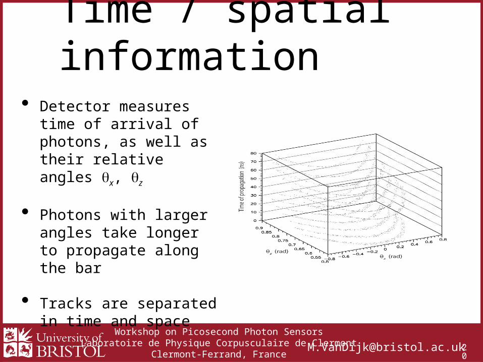
Time / spatial information
• Detector measures time of arrival of photons, as well as their relative angles qx, qz
• Photons with larger angles take longer to propagate along the bar
• Tracks are separated in time and space
Workshop on Picosecond Photon SensorsLaboratoire de Physique Corpusculaire de Clermont
Clermont-Ferrand, [email protected] 2
1
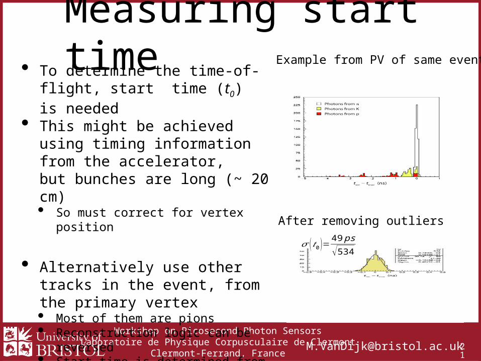
Measuring start time• To determine the time-of-flight, start
time (t0) is needed• This might be achieved using timing
information from the accelerator,but bunches are long (~ 20 cm) • So must correct for vertex position
• Alternatively use other tracks in the event, from the primary vertex• Most of them are pions• Reconstruction logic can be reversed• Start time is determined from their average
assuming they are all pions (outliers from other particles removed)
• Can achieve few-ps resolution on t0
Example from PV of same event
After removing outliers
𝜎 ( 𝑡0 )=49 ps
√534


