
DESCRIPTION
These packaged cooling/heating air conditioners are de-signed for outdoor installation. Only utility and duct connec-tions are required at the point of installation.
The gas-fired heaters have aluminized steel tubular heatexchangers and hot surface to pilot ignition. They are avail-able in natural gas with field conversion to propane.
STANDARD FEATURES and BENEFITS
OPERATING EFFICIENCY - All units provide high operatingefficiencies and have a minimum AFUE of 80% and SEER of 10or above. All efficiencies exceed legislated minimum levels.
ON SITE FLEXIBILITY - All model sizes share a common,compact design cabinet with a single footprint. The installerhas the flexibility of setting one curb and placing the propertonnage unit on that curb after the internal load has been de-termined. Field convertible duct connections from side shot todown shot allows the installer to have greater flexibility andneeds to carry less inventory.
LOWER INSTALLATION COST - Installation time and costsare reduced by easy power and control wiring connections.The small base dimension means less space is required onthe ground or roof, plus, the installer can fit this unit betweenthe wheel wells of full size pick-up truck. All models are wellunder 500 pounds.
All units are completely wired, charged with R-22 and testedprior to shipment. Unique test stations using a new state of theart computerized process system are used to insure productquality.
Refrigerant charge, and component part numbers are verifiedvia computers at installation. Vital run test statistics such as sys-tem pressure, motor currents, air velocity and temperature, unitvibration, and gas system safeties are monitored and recordedby the system to insure unit performance.
Equal size, side supply and return duct connections allowseasy hook-up of ducts to match low crawl spaces without tran-sition pieces.
UTILITY CONNECTIONS MADE EASY - Gas and electricutility knockouts are provided through the bottom as well asthe side of the unit. Utility connections can be made quicklyand with a minimum amount of field labor. A field supplied andfield installed electrical disconnect switch must be installed.
CONVERTIBLE AIRFLOW DESIGN - The bottom duct open-ings are covered when they leave the factory ready to be usedfor a side supply / side return application. If a bottom supply / bot-tom return application is desired, you simply remove the twopanels from the bottom of the unit and place them in the sidesupply / side return duct openings. No panel cutting is requiredand no accessory panel is necessary. Convertible airflow designallows maximum field flexibility and minimum inventory.
CONDENSATE PAN - Anon-corrosive, long-lasting, water-tightpan is positioned below the evaporator coil to collect and drainall condensate. Less collection of stagnate condensate willbuild-up. The condensate pan conforms to ASHRAE 62-89standards (Ventilation for Acceptable Indoor Air Quality).
CONDENSATE DRAIN - The heavy duty, 3/4 inch NPTI cop-per connection is more tolerable during installation and ismore
durable over time. The connection is rigidly mounted to as-sure proper fit and leak tight seal.
FOR DISTRIBUTION USE ONLY - NOT TO BE USED AT POINT OF RETAIL SALE
036-21232-002-B-1004
Champion Series
SINGLE PACKAGEGAS/ELECTRICAIR-COOLEDAIR CONDITIONERS
D1NA018 THRU 048AND D2NA0601-1/2 THRU 5 NOMINAL TONS10 SEER / 80% AFUE
®

DURABLE FINISH - With a heavy duty cabinet made ofpowder-painted, galvanized steel the neutral color blends intosurrounding areas. The powered paint, provides a better paintto steel bond, which resists corrosion and rust creep. The spe-cial primer formulas and glossy earth tone finish insure lessfading when exposed to sunlight and offers a more attractiveon site appearance. This paint finish exceeds ASTM-B117standards for 1000 hour salt spray rating. The highest in theindustry.
FULL PERIMETER BASE RAILS - The easily removablebase rails provide a solid foundation for the entire unit andprotects the unit during shipment. The rails provide fork lift ac-cess from all sides, and rigging holes are also provided so thatan overhead crane can be used to place the units on a roof.On applications when the unit is placed on a pad, the base willkeep the unit off the pad to deter corrosion. On applicationswhere height is limited, the� �
� inch high base rails may be re-moved on location.
MORE ATTRACTIVE APPEARANCE - Asingle piece “WaterShed” top cover containing a top discharge condenser fan ar-rangement requires less square footage on installation andprovides a wider variety of installations. The one piece designadds greater water integrity. Rounded corners with water dripedges add to the attractive appearance. The cabinet panelshave a non-fibrous insulation that does not add insulation fi-bers into conditioned area.
TOP DISCHARGE - The top discharge condenser fan doesnot disrupt neighboring areas or does this dry-out vegetationsurrounding the unit. The warm air from the top mounted fan isblown up away from the structure and any landscaping. Thisallows compact location on multi-unit applications.
CONDENSER COIL GRILLE - A multi-piece totally enclosed,rigidly mounted condenser coil grille provides protection fromobjects and personal after installation and provides protectionduring transit and installation.
LOW OPERATING SOUND LEVEL - The upward air flow car-ries the normal operating noise up and away from the livingarea. The rigid top panel effectively isolates any motor sound.Isolator mounted compressor and the rippled fins of the con-denser coil muffle the normal fan motor and compressor oper-ating sounds. The unique formed base pan also aids in soundalterations with it's “Super-Structure” design. This designstrategically places embossments in the pan for optimumstrength and rigidity.
FAN SYSTEM - All models operate over a wide range of designconditions with a 3-speed direct-drive fan motor. These unitseasily match all types of applications and provides greater onsite flexibility to match comfort requirement. Single phase mod-els have the “Comfort-Match” system that allows different speedtaps for heating or cooling operations. This allows maximumcomfort conditions.
SIMPLE CONTROL CIRCUIT - A low voltage printed circuitboard contains a diagnostic indicator light and a low voltageterminal strip. An additional set of pin connectors is also pro-vided to simplify the field interface of external controls. Mate-n-lock plug connectors are used. The electrical control
box is not located in the compressor compartment. The con-trols are mounted on a “Control-Tilt” control panel to allow theaccess cover to be removed for trouble shooting and mainte-nance without affecting the normal system operating pres-sures. All wiring internal to the unit is color/number coded.
PROTECTED COMPRESSOR - The compressor is internallyprotected against high pressure and temperature. This is ac-complished by the simultaneous operation of high pressurerelief valve and a temperature sensor which protect the com-pressor if undesirable operating conditions occur.
EXCLUSIVE COIL DESIGN - Grooved copper tubes and en-hanced aluminum fin construction improves heat transfer formaximum efficiency and durability.
HEAT EXCHANGERS - Are corrosion-resistant, aluminized-steel tubular construction to provide long-life, trouble-free opera-tion. The unique blow-thru design also assures that condensatedoes not collect in humid areas when in the cooling cycle. Thisadds to longer heat exchanger life and higher long term efficien-cies.
“POST PURGE” INDUCED DRAFT COMBUSTION - Ex-hausts combustion products from the heat exchanger uponcompletion of the heating cycle to prolong the heat exchangerlife.
SELF DIAGNOSTIC FAN CONTROL MODULE - Due to thisself diagnostic control, less on site time is required to troubleshoot these units.
HOT SURFACE TO PILOT IGNITION - Provides faster heat de-livery. This ignition is highly reliable, durable and eliminates nui-sance lockouts. Also assures starts in damp conditions.
MULTI PORT IN-SHOT BURNERS - No field adjustment isrequired to mix the air and gas. These burners are con-structed of high-grade corrosion-resistant, aluminized-steel.
LOW MAINTENANCE - Long life, permanently lubricatedcondenser and evaporator fan motor bearings need no an-nual maintenance adding greater reliability to the unit. Blowerassembly can be easily cleaned by the unique “Slip- Track”slide-out blower assembly.
SECURED SERVICE ACCESS PORTS - Protected, externallymounted, re-usable service access ports are provided on boththe high and low lines for ease of evacuating and charging thesystem. No final field mounting required.
EASY SERVICE ACCESS - A large, single panel covers theelectrical and gas controls makes servicing easy. The blowercompartment has an additional large panel with a built-in han-dle tab. Removing this panel will allow the blower assembly toslide-out for easy removal for maintenance and ease of trou-ble shooting.
REPLACEMENT PARTS - The installer has no need to carryan inventory of unique parts or needs special training to re-place any of the components parts for these units. All are eas-ily obtained from Source 1 or other part houses.
SYSTEM INTEGRATION - Each unit has the internal ability tointegrate an electronic air cleaner or humidifier to work in con-junction with the base unit.
036-21232-002-B-1004
2 Unitary Products Group
STANDARD FEATURES and BENEFITS - continued

LOW NOX KIT - Kit includes all the necessary hardware andinstructions to field convert units to reduce emissions to lessthan 40 nanogram per Joule. California requirement on sin-gle phase models only.
PROPANE CONVERSION KIT - Kit includes burner orifices,gas valve conversion and installation instructions necessaryto field convert unit from natural gas to propane.
HIGH ALTITUDE CONVERSION KIT (Natural Gas/Pro-pane) - Kit includes all necessary labels and instructions nec-essary to field alter units with natural gas/propane. Burnerorifices must be obtained from Source 1 Parts. Propane Con-version Kit must be obtained separately..
ECONOMIZER DOWN DISCHARGE / SUPPLY KIT - Modu-lating integrated economizer provides simultaneous opera-tion between the mechanical cooling and economizeroperation. Independent blade design insures proper controland less than 1% leak rate. Includes hood and mesh birdscreen filter integrated into the hood, dry bulb sensor and re-lief damper. Separate field accessories of single enthalpy anddual enthalpy are also available. Kit also includes capability torelieve up to 25% air thru built-in barometric relief damper.
SINGLE ENTHALPY SENSOR - Sensor replaces dry bulbsensor standard in economizer kit. Provides improved econo-mizer operation by sensing the dry bulb temperature from out-doors plus the enthalpy content of the outdoor air.
DUAL ENTHALPY SENSOR - Additional sensor to single en-thalpy sensor. Sensor senses both the return air temperaturedry bulb and humidity in conjunction with the single enthalpyto determine the most economical mix. Single Enthalpy sen-sor also required.
UPGRADE SAFETY PACKAGE - Contains screw in typeHigh pressure, Low Pressure/Loss of Charge switch, freezeprotection switch and lockout relay. Switches are placed ontoexisting scharder ports located in the unit by furnished adapt-ers. When abnormal conditions are sensed through the pres-sure switches, the unit will lock out preventing any furtheroperation until reset or problem is corrected. Package agencyapproved.
HAIL GUARD KIT - Kit contains protected grilles made of ex-panded aluminum grilles with full perimeter ��
� inch frame.Sloped hoods are also included to assure maximum protec-tion.
ANTI SHORT CYCLE TIMER - Automatically prevents thecompressor from restarting for 5 minutes after cycled off. Notrequired if Thermostat 2ET07700224 and 2ET04700224 areused.
FILTER / FRAME KIT (Single Phase only) - Kit contains thenecessary hardware to field install return air filters into thebase unit. Pre-cut filter racks and appropriate cleanable stan-dard size filters are shipped in one kit. The filter rack is suit-able for either 1" or 2" filters. (1" filter is supplied) This kit isavailable for single phase horizontal or vertical duct applica-tion only. Standard in all 3 Phase models.
MOTORIZED FRESH AIR DAMPER - Designed for ductmounted side return and unit mounted down shot return appli-cations. Damper capabile of providing 0% thru 50% of out-door air (field supplied). Closes on power loss, includes hoodand screen assembly.
RECTANGLE TO ROUND ADAPTERS - Kit includes onesupply and one return air rectangle to round duct adapter.Adapters are preformed and designed to fit over current ductopenings on the base unit. Transition is from15" square to 14"round.
ROOF CURBS - NRCA approved curbs provide proper fit tobase unit for rooftop installations. Curbs are designed to beassembled through hinge pins in each corner. Kit also pro-vides seal strip to assure a water tight seal. 8 and 14 inch highroof curbs are available.
MANUAL OUTDOOR DAMPER - Provides 0% thru 50% out-door air capability (field adjustable). Designed for ductmounted side return and unit mounted down shot return appli-cations. Includes hood and screen assembly.
WALL THERMOSTAT - The units are designed to operatewith 24-volt electronic and electro-mechanical thermostats.All units can operate with single stage heat / single stage coolthermostats - with or without the economizer.
LOW AMBIENT KIT - Kit provides necessary hardware toconvert unit to operate in cooling cycle down to 0° F. Standardunit operation 45° F.
TRANSFORMER KIT - Kit provides necessary hardware toprovide single phase models from factory furnished 40 VAtransformer capability to 75 VA transformer capability.
BURGLAR BAR KIT - Designed to work with listed roofcurbs. These burglar bar kits deter entry through the base unitduct work.
036-21232-002-B-1004
Unitary Products Group 3
FIELD-INSTALLED ACCESSORIES
D 1 N A 0 60 6N0 342
PRODUCT NOMENCLATURE
PRODUCT GENERATION
1 = 1st Generation2 = 2nd Generation
PRODUCT CATEGORY
D = Single PackageAir Conditioner
PRODUCT IDENTIFIER
NA = 10 SEERGas Heat / Electric Cool
NOMINAL COOLINGCAPACITY (MBH)
018 = 18,000 BTUH024 = 24,000 BTUH030 = 30,000 BTUH036 = 36,000 BTUH042 = 42,000 BTUH048 = 48,000 BTUH060 = 60,000 BTUH
VOLTAGE CODE
06 = 208/230-1-6025 = 208/230-3-6046 = 460-3-6058 = 575-3-60
FACTORYINSTALLEDGAS HEAT
N = Natural GasHeat Installed
NOMINAL GAS HEATINGOUTPUT CAPACITY
036 = 36,000 BTUH 065 = 65,000 BTUH056 = 56,000 BTUH 090 = 90,000 BTUH072 = 72,000 BTUH 110 = 110,000 BTUH

4 Unitary Products Group
036-21232-002-B-1004
� � � � � � � � � � � �
� � � � � � � �
� � �
� � � � � � � � � � � � � � � � � � � � � � � � � � �
� � � � � � � � � � � � � � � � � � � � � � � � �
� � � � � � � � � � � � � � � � � � � � � � � � �
� � � � � � � � � � � � � � � � � � � � � � � � �
� � � � � � � �
� � � � � � � � �
� � � � � � � �
� � � � � � � � � � � � � �
� � � � � � � �
� � � � � � � � � � � � � �
� � � � � � � � �
� � � � � � � � � � � �
� � � � � � � � � � � � � � � � � �
� � � � � � � � � � � �
� � � � � � � � � � � � � � �
� � � �
� � � � � � � � � � � � � � � � � � � � � � �
� � � � � � � � � � � � � � � � � � � � � � �� � � � � � � � � �
� � � � � � � � � � �
� � � � � � � � � �
� � �
� � � � � � � � � � � � � � � � � � � �
� � � � � � � � � � � � � �
� � � � � � � � � � � � � �
� � � � � � �
� � � � � � � � �
� � � � � � � � � � �
� � � �
� � � � � � � � � �
� � � � � � � � � �
� � � � � � � � � � � � � �
� � � �
� � � � � � � �
� � � � � � � � �
� � � � � � � � � �
� � � � � �
� � � � � � � � � � � � � � � � � � �
� � � � � � � � � � � � � � � � � � � � � �
� � � � � � � � � � � � � � � � � �
PHYSICAL DATAMODELS
DNA018 024 030 036 042 048 060
EVAPORATORBLOWER
CENTRIFUGAL BLOWER (Dia. x Wd. in.) 10 X 8 10 X 8 10 X 8 11 x 10 11 x 10 12 x 11 12 x 11
FAN MOTOR HP (Three Speed) ��
��
��
��
�� 1.0 1.0
EVAPORATORCOIL
ROWS DEEP 2 2 2 2 3 3 3
FINS PER INCH 14 13 13 15 13 13 13
FACE AREA (Sq. Ft.) 2.25 3.5 3.5 3.5 3.5 4.5 4.5
CONDENSERFAN
PROPELLER DIA. (in.) 22 22 22 22 22 22 22
FAN MOTOR HP ��
��
��
��
��
��
��
NOM. CFM TOTAL 1,800 2,200 2,400 2,400 2,400 3,000 3,000
CONDENSERCOIL
ROWS DEEP 1 1 1 1 1 1 1
FINS PER INCH 13 13 16 20 20 20 20
FACE AREA (Sq. Ft.) 8.3 8.3 11.7 11.7 11.7 14.8 14.8
CHARGE REFRIGERANT 22 (lbs./oz.) 3 / 2 3 / 16 4 / 12 4 / 3 4 / 12 6 / 0 5 / 4
FILTER* FACE AREA (Sq. Ft.) / SIZE (NOMINAL) 2.6/20x20 2.6/20x20 2.6/20x20 2.6/20x20 2.6/20x20 3.3/20x12 3.3/20x12
FURNACESECTION
NATURAL GAS BURNER ORIFICE NO.(Drill size) 43 43 43 43 43 40 40
PROPANE BURNER ORIFICE NO.(Drill size) 55 55 55 55 55 53 53
GAS CONNECTION SIZE �� NPTI �
� NPTI �� NPTI �
� NPTI �� NPTI �
� NPTI �� NPTI
COMPRESSORTYPE
HERMETICALLY SEALED(R = RECIPROCATING, S = Scroll) R R R R R S S
* = Three phase 018 thru 042 size units are supplied with one (1) filter and on three phase 048 and 060 size units two (2) filters are supplied. Single phase units are shipped without filters.See “FILTER / FRAME KIT” on page 3.
Unitary Products Group 5
036-21232-002-B-1004
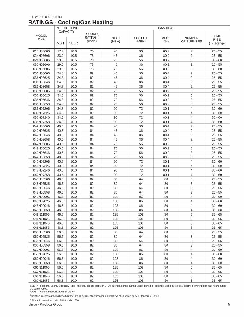
RATINGS - Cooling/Gas Heating
MODELDNA
NET COOLINGCAPACITY 1
SOUNDRATING 2
(dbels)
GAS HEAT
INPUT(MBH)
OUTPUT(MBH)
AFUE(%)
NUMBEROF BURNERS
TEMP.RISE
(�F) RangeMBH SEER
018N03606 17.9 10.0 76 45 36 80.2 2 25 - 55024N03606 23.0 10.5 78 45 36 80.2 2 25 - 55024N05606 23.0 10.5 78 70 56 80.2 3 30 - 60030N03606 29.0 10.5 78 45 36 80.2 2 25 - 55030N05606 29.0 10.5 78 70 56 80.2 3 30 - 60036N03606 34.8 10.0 82 45 36 80.4 2 25 - 55036N03625 34.8 10.0 82 45 36 80.4 2 25 - 55036N03646 34.8 10.0 82 45 36 80.4 2 25 - 55036N03658 34.8 10.0 82 45 36 80.4 2 25 - 55036N05606 34.8 10.0 82 70 56 80.2 3 25 - 55036N05625 34.8 10.0 82 70 56 80.2 3 25 - 55036N05646 34.8 10.0 82 70 56 80.2 3 25 - 55036N05658 34.8 10.0 82 70 56 80.2 3 25 - 55036N07206 34.8 10.0 82 90 72 80.1 4 30 - 60036N07225 34.8 10.0 82 90 72 80.1 4 30 - 60036N07246 34.8 10.0 82 90 72 80.1 4 30 - 60036N07258 34.8 10.0 82 90 72 80.1 4 30 - 60042N03606 40.5 10.0 84 45 36 80.4 2 25 - 55042N03625 40.5 10.0 84 45 36 80.4 2 25 - 55042N03646 40.5 10.0 84 45 36 80.4 2 25 - 55042N03658 40.5 10.0 84 45 36 80.4 2 25 - 55042N05606 40.5 10.0 84 70 56 80.2 3 25 - 55042N05625 40.5 10.0 84 70 56 80.2 3 25 - 55042N05646 40.5 10.0 84 70 56 80.2 3 25 - 55042N05658 40.5 10.0 84 70 56 80.2 3 25 - 55042N07206 40.5 10.0 84 90 72 80.1 4 30 - 60042N07225 40.5 10.0 84 90 72 80.1 4 30 - 60042N07246 40.5 10.0 84 90 72 80.1 4 30 - 60042N07258 40.5 10.0 84 90 72 80.1 4 30 - 60048N06506 46.5 10.0 82 80 64 80 3 25 - 55048N06525 46.5 10.0 82 80 64 80 3 25 - 55048N06546 46.5 10.0 82 80 64 80 3 25 - 55048N06558 46.5 10.0 82 80 64 80 3 25 - 55048N09006 46.5 10.0 82 108 86 80 4 30 - 60048N09025 46.5 10.0 82 108 86 80 4 30 - 60048N09046 46.5 10.0 82 108 86 80 4 30 - 60048N09058 46.5 10.0 82 108 86 80 4 30 - 60048N11006 46.5 10.0 82 135 108 80 5 35 - 65048N11025 46.5 10.0 82 135 108 80 5 35 - 65048N11046 46.5 10.0 82 135 108 80 5 35 - 65048N11058 46.5 10.0 82 135 108 80 5 35 - 65060N06506 56.5 10.0 82 80 64 80 3 25 - 55060N06525 56.5 10.0 82 80 64 80 3 25 - 55060N06546 56.5 10.0 82 80 64 80 3 25 - 55060N06558 56.5 10.0 82 80 64 80 3 25 - 55060N09006 56.5 10.0 82 108 86 80 4 30 - 60060N09025 56.5 10.0 82 108 86 80 4 30 - 60060N09046 56.5 10.0 82 108 86 80 4 30 - 60060N09058 56.5 10.0 82 108 86 80 4 30 - 60060N11006 56.5 10.0 82 135 108 80 5 35 - 65060N11025 56.5 10.0 82 135 108 80 5 35 - 65060N11046 56.5 10.0 82 135 108 80 5 35 - 65060N11058 56.5 10.0 82 135 108 80 5 35 - 65
SEER = Seasonal Energy Efficiency Ratio - the total cooling output in BTU's during a normal annual usage period for cooling divided by the total electric power input in watt-hours duringthe same period.AFUE = Annual Fuel Utilization Efficiency.1 Certified in accordance with the Unitary Small Equipment certification program, which is based on ARI Standard 210/240.2 Rated in accordance with ARI Standard 270.
6 Unitary Products Group
036-21232-002-B-1004
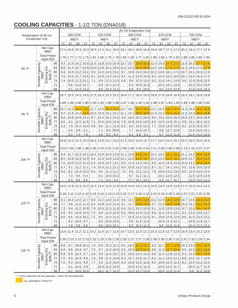
COOLING CAPACITIES - 1-1/2 TON (DNA018)
Temperature of Air onCondenser Coil
Air On Evaporator Coil450 CFM 525 CFM 600 CFM 675 CFM 750 CFM
WB�F WB�F WB�F WB�F WB�F72 67 62 57 72 67 62 57 72 67 62 57 72 67 62 57 72 67 62 57
85 �F
Net Cap.MBH 17.4 16.6 15.3 15.3 18.3 17.4 16.1 16.0 19.1 18.2 16.8 16.8 19.6 18.7 17.2 17.2 20.1 19.2 17.7 17.6
Total PowerInput KW 1.78 1.77 1.72 1.75 1.81 1.80 1.75 1.78 1.83 1.83 1.77 1.81 1.85 1.84 1.79 1.82 1.86 1.86 1.80 1.84
Sen
sibl
eC
apac
ityM
BH
1
Ent
erin
gD
ryB
ulb,
�F
86 9.3 11.9 14.1 15.0 11.0 13.8 15.5 15.9 12.7 15.7 16.8 16.8 12.3 15.5 17.2 17.2 11.9 15.2 17.7 17.683 8.8 11.4 13.7 14.5 10.0 12.8 15.2 15.6 11.2 14.2 16.8 16.8 11.2 14.4 17.2 17.2 11.3 14.6 17.5 17.680 8.3 11.0 13.2 14.1 9.0 11.9 14.3 15.2 9.7 12.8 15.4 16.4 10.2 13.4 16.1 17.0 10.7 14.1 16.9 17.677 7.9 10.5 12.7 13.6 8.1 10.9 13.3 14.2 8.2 11.3 13.9 14.9 9.2 12.4 15.1 16.0 10.1 13.5 16.4 17.074 7.4 10.0 12.3 13.1 7.1 9.9 12.3 13.3 6.8 9.8 12.4 13.4 8.2 11.4 14.1 14.9 9.6 12.9 15.8 16.571 - 9.6 11.8 12.7 - 8.9 11.4 12.3 - 8.3 10.9 11.9 - 10.3 13.1 13.9 - 12.3 15.2 15.968 - 9.1 11.3 12.2 - 8.0 10.4 11.3 - 6.8 9.4 10.4 - 9.3 12.0 12.9 - 11.8 14.6 15.3
95 �F
Net Cap.MBH 16.7 15.5 14.5 14.5 17.5 16.3 15.3 15.2 18.4 17.1 16.0 16.0 18.9 17.6 16.4 16.4 19.3 18.1 16.8 16.8
Total PowerInput KW 1.89 1.89 1.86 1.85 1.93 1.92 1.89 1.88 1.97 1.96 1.93 1.92 1.98 1.97 1.94 1.93 1.99 1.98 1.95 1.94
Sen
sibl
eC
apac
ityM
BH
1
Ent
erin
gD
ryB
ulb,
�F
86 10.7 13.2 14.5 14.5 11.7 14.5 15.3 15.2 12.7 15.7 16.0 16.0 12.1 15.3 16.4 16.4 11.5 14.9 16.8 16.883 9.3 11.9 14.2 14.5 10.2 13.0 15.1 15.2 11.1 14.1 16.0 16.0 11.0 14.2 16.4 16.4 11.0 14.3 16.8 16.880 8.0 10.6 12.9 13.1 8.7 11.5 14.1 14.3 9.4 12.5 15.2 15.5 9.9 13.1 16.0 16.2 10.4 13.7 16.8 16.877 6.6 9.2 11.5 11.8 7.2 10.0 12.6 12.9 7.8 10.9 13.6 13.9 8.8 12.0 14.9 15.1 9.8 13.1 16.2 16.274 5.3 7.9 10.2 10.4 5.8 8.6 11.1 11.4 6.2 9.3 12.0 12.3 7.7 10.9 13.8 14.0 9.2 12.6 15.6 15.771 - 6.5 8.9 9.1 - 7.1 9.6 99.9 - 7.7 10.4 10.7 - 9.8 12.7 12.9 - 12.0 15.0 15.168 - 5.2 7.5 7.8 - 5.6 8.2 8.4 - 6.1 8.8 9.1 - 8.7 11.6 11.8 - 11.4 14.5 14.5
105 �F
Net Cap.MBH 15.6 14.2 13.4 13.3 16.4 14.9 14.1 14.0 17.2 15.6 14.8 14.7 17.7 16.0 15.2 15.1 18.2 16.5 15.6 15.5
Total PowerInput KW 2.03 2.00 1.98 1.98 2.06 2.03 2.01 2.01 2.09 2.06 2.04 2.04 2.11 2.08 2.06 2.06 2.13 2.10 2.07 2.07
Sen
sibl
eC
apac
ityM
BH
1
Ent
erin
gD
ryB
ulb,
�F
86 9.4 11.7 13.3 13.1 10.2 12.8 14.0 13.9 11.1 13.9 14.8 14.7 11.1 14.1 15.2 15.1 11.1 14.3 15.6 15.583 8.5 10.9 12.9 12.9 9.3 11.9 13.8 13.8 10.1 12.9 14.8 14.7 10.3 13.3 15.2 15.1 10.6 13.7 15.6 15.580 7.6 10.0 12.0 12.0 8.3 10.9 13.2 13.1 9.0 11.9 14.3 14.2 9.5 12.5 14.9 14.9 10.0 13.1 15.6 15.577 6.7 9.1 11.2 11.1 7.4 10.0 12.2 12.2 8.0 10.8 13.2 13.2 8.7 11.7 14.1 14.1 9.5 12.6 15.0 15.074 5.9 8.2 10.3 10.2 6.4 9.0 11.3 11.2 7.0 9.8 12.2 12.1 7.9 10.9 13.3 13.3 8.9 12.0 14.5 14.471 - 7.4 9.4 9.4 - 8.1 10.3 10.2 - 8.7 11.2 11.1 - 10.1 12.5 12.5 - 11.5 13.9 13.968 - 6.5 8.6 8.5 - 7.1 9.3 9.3 - 77.7 10.1 10.1 - 9.3 11.7 11.7 - 10.9 13.4 13.3
115 �F
Net Cap.MBH 14.5 12.8 12.3 12.2 15.2 13.4 12.9 12.8 15.9 14.0 13.5 13.4 16.5 14.5 14.0 13.8 17.0 15.0 14.4 14.3
Total PowerInput KW 2.16 2.11 2.10 2.10 2.19 2.14 2.13 2.13 2.22 2.17 2.16 2.16 2.24 2.19 2.18 2.18 2.27 2.21 2.20 2.20
Sen
sibl
eC
apac
ityM
BH
1
Ent
erin
gD
ryB
ulb,
�F
86 8.1 10.2 12.0 11.7 8.8 11.2 12.8 12.5 9.6 12.2 13.5 13.4 10.2 12.9 14.0 13.8 10.7 13.6 14.4 14.383 7.7 9.8 11.6 11.3 8.4 10.8 12.6 12.3 9.1 11.7 13.5 13.4 9.7 12.4 14.0 13.8 10.2 13.1 14.4 14.380 7.3 9.4 11.2 10.9 7.9 10.3 12.3 11.9 8.6 11.2 13.3 12.9 9.1 11.9 13.9 13.9 9.7 12.6 14.4 14.377 6.9 9.0 10.8 10.5 7.5 9.9 11.8 11.5 8.2 10.8 12.9 12.5 8.6 11.4 13.4 13.1 9.1 12.0 13.9 13.774 6.5 8.6 10.4 10.1 7.1 9.5 11.4 11.0 7.7 10.3 12.4 12.0 8.1 10.9 12.9 12.6 8.6 11.5 13.3 13.271 - 8.2 10.0 9.7 - 9.0 10.9 10.6 - 9.8 11.9 11.5 - 10.4 12.3 12.1 - 10.9 12.8 12.768 - 7.8 9.6 9.2 - 8.6 10.5 10.1 - 9.3 11.4 11.0 - 9.9 11.8 11.6 - 10.4 12.3 12.1
125 �F
Net Cap.MBH 13.5 11.4 11.2 11.1 14.1 11.9 11.7 11.6 14.7 12.5 12.3 12.1 15.3 12.9 12.7 12.6 15.9 13.4 13.2 13.0
Total PowerInput KW 2.30 2.23 2.22 2.23 2.32 2.25 2.25 2.26 2.35 2.27 2.27 2.28 2.38 2.30 2.30 2.31 2.41 2.33 2.33 2.34
Sen
sibl
eC
apac
ityM
BH
1
Ent
erin
gD
ryB
ulb,
�F
86 6.8 8.7 10.8 10.3 7.4 9.6 11.5 11.2 8.1 10.5 12.3 12.1 9.2 11.7 12.7 12.6 10.3 13.0 13.2 13.083 6.8 8.8 10.3 9.7 7.5 9.7 11.3 10.9 8.2 10.5 12.3 12.1 9.0 11.5 12.7 12.6 9.8 12.5 13.2 13.080 6.9 8.9 10.4 9.7 4.6 9.8 11.4 10.7 8.2 10.6 12.4 11.6 8.8 11.3 12.8 12.3 9.3 12.0 13.2 13.077 7.0 9.0 10.4 9.8 7.6 9.8 11.4 10.8 8.3 10.7 12.5 11.7 8.5 11.1 12.6 12.1 8.8 11.5 12.7 12.574 7.0 9.0 10.5 9.9 7.7 9.9 11.5 10.8 8.4 10.8 12.5 11.8 8.3 10.9 12.4 11.9 8.2 10.9 12.2 12.071 - 9.1 10.6 9.9 - 10.0 11.6 10.9 - 10.9 12.6 11.9 - 10.6 12.2 11.7 - 10.4 11.7 11.568 - 9.2 10.6 10.0 - 10.1 11.7 11.0 - 11.0 12.7 12.0 - 10.4 11.9 11.4 - 9.9 11.2 10.9
1 = These capacities are net capacities - indoor fan heat deducted.
ALL SENSIBLE CAPACITY

Unitary Products Group 7
036-21232-002-B-1004
COOLING CAPACITIES - 2 TON (DNA024)
Temperature of Air onCondenser Coil
Air On Evaporator Coil600 CFM 700 CFM 800 CFM 900 CFM 1,000 CFM
WB�F WB�F WB�F WB�F WB�F72 67 62 57 72 67 62 57 72 67 62 57 72 67 62 57 72 67 62 57
85 �F
Net Cap.MBH 24.1 22.5 20.9 21.3 24.9 23.3 21.6 22.1 25.8 24.1 22.3 22.8 25.9 24.2 22.5 22.9 26.1 24.4 22.6 23.1
Total PowerInput KW 2.28 2.25 2.21 2.21 2.31 2.28 2.24 2.24 2.34 2.31 2.27 2.27 2.44 2.41 2.37 2.37 2.53 2.51 2.46 2.46
Sen
sibl
eC
apac
ityM
BH
1
Ent
erin
gD
ryB
ulb,
�F
86 12.9 16.5 19.7 20.4 15.2 19.0 21.0 21.6 17.5 21.6 22.3 22.8 16.8 21.2 22.5 22.9 16.2 20.7 22.6 23.183 12.3 15.9 19.1 19.7 13.9 17.8 20.7 21.3 15.5 19.6 22.3 22.8 15.5 19.8 22.5 22.9 15.5 19.9 22.6 23.180 11.7 15.3 18.5 19.1 12.6 16.5 20.0 20.6 13.5 17.7 21.4 22.2 14.1 18.4 22.0 22.6 14.7 19.2 22.6 23.177 11.1 14.6 17.9 18.5 11.3 15.2 18.7 19.3 11.5 15.7 19.4 20.2 12.7 17.0 20.6 21.3 13.9 18.4 21.8 22.374 10.4 14.0 17.3 17.9 10.0 13.9 17.4 18.1 9.6 13.7 17.5 18.2 11.3 15.7 19.3 19.9 13.1 17.6 21.1 21.571 - 13.4 16.6 17.3 - 12.6 16.1 16.8 - 11.7 15.5 16.2 - 14.3 17.9 18.5 - 16.8 20.3 20.868 - 12.8 16.0 16.7 - 11.3 14.8 15.5 - 9.8 13.5 14.3 - 12.9 16.5 17.1 - 16.1 19.5 20.0
95 �F
Net Cap.MBH 23.5 21.4 20.2 20.4 24.0 21.9 20.7 20.9 24.6 22.4 21.2 21.3 25.0 22.8 21.5 21.7 25.4 23.2 21.9 22.1
Total PowerInput KW 2.41 2.38 2.33 2.33 2.45 2.42 2.37 2.37 2.50 2.46 2.40 2.41 2.59 2.56 2.50 2.50 2.69 2.66 2.60 2.60
Sen
sibl
eC
apac
ityM
BH
1
Ent
erin
gD
ryB
ulb,
�F
86 15.0 18.3 20.2 20.4 16.2 19.8 20.7 20.9 17.4 21.2 21.2 21.3 16.8 20.9 21.5 21.7 16.2 20.5 21.9 22.183 13.2 16.5 19.9 20.0 14.2 17.8 20.5 20.6 15.2 19.1 21.2 21.3 15.3 19.4 21.5 21.7 15.4 19.8 21.9 22.180 11.4 14.7 18.1 18.2 12.2 15.8 19.5 19.5 13.1 16.9 20.9 20.9 13.9 18.0 21.4 21.5 14.6 19.0 21.9 22.177 9.6 13.0 16.4 16.4 10.3 13.9 17.5 17.5 10.9 14.8 18.7 18.7 12.4 16.5 19.9 20.0 13.9 18.2 21.1 21.374 7.8 11.2 14.6 14.6 8.3 11.9 15.6 15.6 8.8 12.7 16.6 16.6 10.9 15.0 18.5 18.6 13.1 17.4 20.3 20.671 - 9.4 12.8 12.8 - 9.9 13.6 13.6 - 10.5 14.4 14.4 - 13.6 17.0 17.1 - 16.6 19.6 19.768 - 7.6 11.0 11.0 - 8.0 11.6 11.6 - 8.4 12.3 12.3 - 12.1 15.6 15.6 - 15.9 18.8 19.0
105 �F
Net Cap.MBH 21.7 19.5 18.5 18.6 22.3 20.1 19.0 19.1 22.9 20.6 19.5 19.6 23.2 20.9 19.8 19.9 23.5 21.2 20.1 20.1
Total PowerInput KW 2.55 2.51 2.47 2.45 2.60 2.56 2.51 2.50 2.65 2.60 2.56 2.54 2.74 2.69 2.65 2.63 2.83 2.79 2.74 2.72
Sen
sibl
eC
apac
ityM
BH
1
Ent
erin
gD
ryB
ulb,
�F
86 13.0 16.4 18.1 18.0 14.2 17.8 18.8 18.8 15.3 19.2 19.5 19.6 15.3 19.5 19.8 19.9 15.4 19.8 20.1 20.183 11.9 15.2 17.7 17.5 12.9 16.5 18.6 18.6 13.9 17.8 19.5 19.6 14.3 18.4 19.8 19.9 14.6 19.0 20.1 20.180 10.7 14.1 16.5 16.3 11.6 15.3 17.9 17.7 12.5 16.5 19.3 19.1 13.2 17.4 19.7 19.6 13.9 18.3 20.1 20.177 9.5 12.9 15.4 15.2 10.3 14.0 16.7 16.5 11.1 15.1 18.0 17.7 12.1 16.3 18.6 18.6 13.1 17.5 19.3 19.474 8.4 11.7 14.2 14.0 9.0 12.7 15.4 15.2 9.7 13.7 16.6 16.3 11.1 16.2 17.6 17.5 12.4 16.8 18.6 18.671 - 10.6 13.0 12.9 - 11.4 14.1 13.9 - 12.3 15.2 14.9 - 14.1 16.5 16.4 - 16.0 17.8 17.968 - 9.4 11.9 11.7 - 10.1 12.8 12.6 - 10.9 13.8 13.5 - 13.1 15.4 15.3 - 15.3 17.0 17.1
115 �F
Net Cap.MBH 20.0 17.7 16.8 16.8 20.6 18.2 17.3 17.3 21.2 18.7 17.8 17.8 21.4 19.0 18.0 18.0 21.7 19.2 18.2 18.2
Total PowerInput KW 2.69 2.64 2.60 2.58 2.75 2.70 2.66 2.63 2.80 2.75 2.71 2.68 2.89 2.83 2.79 2.76 2.97 2.92 2.87 2.84
Sen
sibl
eC
apac
ityM
BH
1
Ent
erin
gD
ryB
ulb,
�F
86 11.1 14.4 16.0 15.6 12.2 15.8 16.9 16.7 13.2 17.2 17.8 17.8 13.9 18.1 18.0 18.0 14.6 19.0 18.2 18.283 10.5 13.9 15.5 15.1 11.6 15.3 16.6 16.4 12.6 16.6 17.8 17.8 13.2 17.5 18.0 18.0 13.9 18.3 18.2 18.280 10.0 13.4 14.9 14.5 11.0 14.7 16.4 15.9 11.9 16.0 17.8 17.4 12.5 16.8 18.0 17.8 13.2 17.6 18.2 18.277 9.5 12.8 14.4 14.0 10.4 14.1 15.8 15.4 11.3 15.3 17.2 16.7 11.9 16.1 17.3 17.1 12.4 16.8 17.5 17.574 8.9 12.3 13.9 13.5 9.8 13.5 15.2 14.8 10.7 14.7 16.5 16.1 11.2 15.4 16.7 16.4 11.7 16.1 16.8 16.771 - 11.8 13.3 12.9 - 12.9 14.6 14.2 - 14.0 15.9 15.4 - 14.7 16.0 15.7 - 15.4 16.0 16.068 - 11.2 12.8 12.4 - 12.3 14.0 13.6 - 13.4 15.3 14.8 - 14.0 15.3 15.0 - 14.6 15.3 15.3
125 �F
Net Cap.MBH 18.2 15.8 15.1 15.0 18.9 16.3 15.6 15.5 19.5 16.9 16.2 16.0 19.6 17.0 16.3 16.2 19.8 17.1 16.4 16.3
Total PowerInput KW 2.83 2.77 2.74 2.70 2.89 2.83 2.80 2.76 2.95 2.89 2.86 2.82 3.03 2.97 2.94 2.89 3.11 3.05 3.01 2.97
Sen
sibl
eC
apac
ityM
BH
1
Ent
erin
gD
ryB
ulb,
�F
86 9.1 12.5 13.9 13.2 10.2 13.9 15.0 14.6 11.2 15.3 16.2 16.0 12.5 16.8 16.3 16.2 13.8 18.3 16.4 16.383 9.2 12.6 13.2 12.6 10.3 14.0 14.7 14.3 11.3 15.4 16.2 16.0 12.2 16.5 16.3 16.2 13.1 17.6 16.4 16.380 9.3 12.7 13.3 12.7 10.4 14.1 14.8 14.2 11.4 15.5 16.2 15.6 11.9 16.2 16.3 15.9 12.4 16.9 16.4 16.377 9.4 12.8 13.4 12.8 10.5 14.2 14.9 14.3 11.5 15.6 16.2 15.7 11.6 15.9 16.1 15.6 11.7 16.2 15.7 15.674 9.5 12.9 13.5 12.9 10.6 14.3 15.0 14.4 11.6 15.7 16.2 15.8 11.3 15.6 15.8 15.3 11.0 15.5 15.0 14.971 - 13.0 13.6 13.0 - 14.4 15.1 14.5 - 15.8 16.2 15.9 - 15.3 15.5 15.0 - 14.7 14.3 14.168 - 13.0 13.7 13.1 - 14.5 15.2 14.6 - 15.9 16.2 16.0 - 15.0 15.2 14.7 - 14.0 13.6 13.4
1 = These capacities are net capacities - indoor fan heat deducted.
ALL SENSIBLE CAPACITY

8 Unitary Products Group
036-21232-002-B-1004
COOLING CAPACITIES - 2-1/2 TON (DNA030)
Temperature of Air onCondenser Coil
Air On Evaporator Coil750 CFM 875 CFM 1,000 CFM 1,125 CFM 1,250 CFM
WB�F WB�F WB�F WB�F WB�F72 67 62 57 72 67 62 57 72 67 62 57 72 67 62 57 72 67 62 57
85 �F
Net Cap.MBH 28.1 26.4 24.2 22.6 30.6 28.7 26.3 24.5 32.9 31.0 28.3 26.4 33.2 31.2 28.6 26.7 33.5 31.5 28.8 26.9
Total PowerInput KW 2.99 2.95 2.90 2.89 3.03 2.99 2.94 2.93 3.06 3.02 2.97 2.96 3.13 3.09 3.04 3.03 3.20 3.16 3.11 3.10
Sen
sibl
eC
apac
ityM
BH
1
Ent
erin
gD
ryB
ulb,
�F
86 15.3 19.8 23.6 22.6 18.6 23.6 26.0 24.5 21.9 27.4 28.3 26.4 21.1 26.8 28.6 26.7 20.2 26.2 28.8 26.983 14.5 19.0 22.8 21.9 17.0 21.9 25.6 24.2 19.4 24.9 28.3 26.4 19.3 25.1 28.6 26.7 19.3 25.2 28.8 26.980 13.7 18.2 22.1 21.2 15.3 20.3 24.6 23.6 16.9 22.4 27.2 26.1 17.6 23.3 28.0 26.5 18.3 24.2 28.8 26.977 13.0 17.4 21.3 20.4 13.7 18.7 23.0 22.0 14.5 20.0 24.7 23.6 15.9 21.6 26.3 24.8 17.3 23.3 27.8 25.974 12.2 16.7 20.5 19.6 12.1 17.1 21.4 20.4 12.0 17.5 22.2 21.1 14.2 19.9 24.6 23.0 16.4 22.3 26.9 24.971 - 15.9 19.7 18.8 - 15.5 19.8 18.7 - 15.0 19.8 18.7 - 18.2 22.8 21.3 - 21.3 25.9 24.068 - 15.1 19.0 18.1 - 13.8 18.1 17.1 - 12.6 17.3 16.2 - 16.5 21.1 19.6 - 20.4 24.9 23.0
95 �F
Net Cap.MBH 26.8 25.0 22.3 21.4 29.2 27.3 24.3 23.4 31.7 29.6 26.4 25.4 32.0 29.9 26.6 25.6 32.2 30.1 26.8 25.8
Total PowerInput KW 3.18 3.14 3.08 3.07 3.22 3.18 3.11 3.11 3.26 3.22 3.15 3.15 3.34 3.30 3.23 3.22 3.42 3.38 3.30 3.30
Sen
sibl
eC
apac
ityM
BH
1
Ent
erin
gD
ryB
ulb,
�F
86 17.9 22.3 22.3 21.4 19.9 24.9 24.3 23.4 22.0 27.5 26.4 25.4 21.0 26.7 26.6 25.6 19.9 25.9 26.8 25.883 15.6 20.1 22.3 21.4 17.5 22.5 24.3 23.4 19.3 24.9 26.4 25.4 19.1 24.9 26.6 25.6 19.0 24.9 26.8 25.880 13.4 17.8 21.0 20.0 15.0 20.0 23.6 22.4 16.6 22.2 26.1 24.8 17.3 23.1 16.5 25.3 18.0 24.0 26.8 25.877 11.1 15.6 18.8 17.7 12.6 17.5 21.1 19.9 14.0 19.5 23.5 22.2 15.5 21.2 24.6 23.5 17.0 23.0 25.8 24.874 8.9 13.4 16.5 15.5 10.1 15.1 18.7 17.5 11.3 16.8 20.8 19.5 13.7 19.4 22.8 21.7 16.0 22.0 24.9 23.971 - 11.1 14.3 13.3 - 12.6 16.2 15.0 - 14.1 18.1 16.8 - 17.6 21.0 19.8 - 21.0 23.9 22.968 - 8.9 12.1 11.0 - 10.2 13.7 12.6 - 11.5 15.4 14.1 - 15.8 19.2 18.0 - 20.1 22.9 21.9
105 �F
Net Cap.MBH 25.4 23.0 20.6 20.1 27.7 25.0 22.5 21.9 30.0 27.1 24.4 23.8 30.4 27.4 24.7 24.0 30.7 27.8 25.0 24.3
Total PowerInput KW 2.94 3.31 3.23 3.24 2.98 3.36 3.28 3.29 3.03 3.41 3.33 3.34 3.10 3.49 3.41 3.42 3.17 3.57 3.48 3.49
Sen
sibl
eC
apac
ityM
BH
1
Ent
erin
gD
ryB
ulb,
�F
86 15.9 20.0 20.6 20.1 17.7 22.3 22.5 21.9 19.6 24.7 24.4 23.8 19.5 24.9 24.7 24.0 19.5 25.1 25.0 24.383 14.4 18.5 20.5 19.9 16.1 20.7 22.5 21.8 17.8 22.9 24.4 23.8 18.2 23.5 24.7 24.0 18.6 24.1 25.0 24.380 13.0 17.1 19.6 18.8 14.5 19.1 21.9 21.0 16.1 21.2 24.3 23.3 16.9 22.2 24.6 23.8 17.6 23.2 25.0 24.377 11.5 15.6 18.1 17.3 12.9 17.5 20.3 19.5 14.4 19.5 22.5 21.6 15.5 20.9 23.3 22.5 16.7 22.2 24.0 23.474 10.1 14.2 16.6 15.9 11.3 15.9 18.7 17.9 12.6 17.7 20.8 19.8 14.2 19.5 21.9 21.1 15.7 21.3 23.1 22.471 - 12.7 15.2 14.4 - 14.3 17.1 16.3 - 16.0 19.0 18.1 - 18.2 20.6 19.8 - 20.4 22.1 21.568 - 11.3 13.7 13.0 - 12.7 15.5 14.7 - 14.2 17.3 16.3 - 16.8 19.2 18.4 - 19.4 21.2 20.6
115 �F
Net Cap.MBH 24.1 20.9 19.0 18.8 26.2 22.8 20.7 20.5 28.3 24.6 22.4 22.1 28.8 25.0 22.7 22.5 29.2 25.4 23.1 22.8
Total PowerInput KW 2.70 3.47 3.38 3.40 2.75 3.53 3.44 3.47 2.80 3.60 3.50 3.53 2.86 3.68 3.58 3.61 2.92 3.76 3.66 3.69
Sen
sibl
eC
apac
ityM
BH
1
Ent
erin
gD
ryB
ulb,
�F
86 13.9 17.7 19.0 18.8 15.5 19.7 20.7 20.5 17.2 21.8 22.4 22.1 18.1 23.0 22.7 22.5 19.1 24.2 23.1 22.883 13.2 17.0 18.8 18.3 14.8 19.0 20.6 20.2 16.4 21.0 22.4 22.1 17.3 22.2 22.7 22.5 18.2 23.3 23.1 22.880 12.6 16.3 18.1 17.6 14.1 18.3 20.2 19.7 15.6 20.2 22.4 21.8 16.4 21.3 22.7 22.3 17.3 22.4 23.1 22.877 11.9 15.7 17.4 16.9 13.3 17.5 19.5 19.0 14.8 19.4 21.6 21.0 15.6 20.5 21.9 21.5 16.3 21.5 22.2 21.974 11.2 15.0 16.7 16.3 12.6 16.8 18.8 18.2 13.9 13.6 20.8 20.2 14.7 19.6 21.0 20.6 15.4 20.6 21.3 21.071 - 14.3 16.1 15.6 - 16.1 18.0 17.5 - 17.8 20.0 19.4 - 18.7 20.2 19.7 - 19.7 20.4 20.168 - 13.6 15.4 14.9 - 15.3 17.3 16.7 - 17.0 19.2 18.6 - 17.9 19.3 18.9 - 18.8 19.5 19.2
125 �F
Net Cap.MBH 22.7 18.9 17.4 17.5 24.7 20.5 18.9 19.0 26.6 22.2 20.4 20.5 27.2 22.6 20.8 20.9 27.7 23.1 21.3 21.4
Total PowerInput KW 2.45 3.63 3.53 3.57 2.51 3.71 3.60 3.64 2.56 3.79 3.68 3.72 2.62 3.87 3.76 3.80 2.68 3.96 3.84 3.89
Sen
sibl
eC
apac
ityM
BH
1
Ent
erin
gD
ryB
ulb,
�F
86 11.9 15.3 17.4 17.5 13.3 17.2 18.9 19.0 14.7 19.0 20.4 20.5 16.7 21.2 20.8 20.9 18.9 23.4 21.3 21.483 12.0 15.5 17.0 16.7 13.5 17.3 18.7 18.6 14.9 19.1 20.4 20.5 16.3 20.8 20.8 20.9 17.8 22.5 21.3 21.480 12.2 15.6 16.6 16.4 13.6 17.4 18.6 18.3 15.0 19.2 20.5 20.2 16.0 20.4 20.9 20.8 16.9 21.7 21.3 21.477 12.3 15.7 16.7 16.5 13.7 17.5 18.7 18.5 15.1 19.4 20.7 20.4 15.6 20.1 20.5 20.4 16.0 20.8 20.4 20.574 12.4 15.8 16.9 16.8 13.8 17.6 18.8 18.6 15.3 19.5 20.8 20.5 15.2 19.7 20.1 20.1 15.1 19.9 19.5 19.671 - 15.9 17.0 16.7 - 17.8 18.9 18.7 - 19.6 20.9 20.7 - 19.3 19.8 19.7 - 19.0 18.6 18.768 - 16.0 17.1 16.9 - 17.9 19.1 18.8 - 19.8 21.1 20.8 - 19.0 19.4 19.3 - 18.1 17.7 17.8
1 = These capacities are net capacities - indoor fan heat deducted.
ALL SENSIBLE CAPACITY

Unitary Products Group 9
036-21232-002-B-1004
COOLING CAPACITIES - 3 TON (DNA036)
Temperature of Air onCondenser Coil
Air On Evaporator Coil900 CFM 1,050 CFM 1,200 CFM 1,350 CFM 1,500 CFM
WB�F WB�F WB�F WB�F WB�F72 67 62 57 72 67 62 57 72 67 62 57 72 67 62 57 72 67 62 57
85 �F
Net Cap.MBH 36.7 34.6 31.9 30.3 37.9 35.7 32.9 31.3 39.1 36.9 34.0 32.3 39.4 37.1 34.2 32.5 39.6 37.4 34.4 32.7
Total PowerInput KW 3.57 3.51 3.44 3.41 3.64 3.58 3.51 3.48 3.71 3.65 3.58 3.55 3.80 3.73 3.66 3.63 3.88 3.82 3.74 3.71
Sen
sibl
eC
apac
ityM
BH
1
Ent
erin
gD
ryB
ulb,
�F
86 19.8 25.2 29.9 30.3 23.0 28.7 32.0 31.3 26.1 32.1 34.0 32.3 24.8 31.0 34.2 32.5 23.5 29.9 34.4 32.783 18.9 24.3 29.0 29.7 21.0 26.7 31.5 31.0 23.1 29.2 34.0 32.3 22.8 29.0 34.2 32.5 22.4 28.8 34.4 32.780 18.0 23.4 28.1 28.8 19.1 24.8 29.8 30.5 20.1 26.2 31.5 32.3 20.7 27.0 32.4 32.5 21.3 27.7 33.3 32.777 17.1 22.4 27.2 27.9 17.1 22.8 27.8 28.6 17.2 23.2 28.5 29.3 18.7 24.9 30.4 30.5 20.2 26.6 32.2 31.674 16.1 21.5 26.2 26.9 15.2 20.9 25.9 26.6 14.2 20.2 25.5 26.3 16.7 22.9 28.3 28.4 19.1 25.5 31.1 30.571 - 20.6 25.3 26.0 - 18.9 23.9 24.7 - 17.3 22.6 23.4 - 20.9 26.3 26.4 - 24.4 30.0 29.468 - 19.7 24.4 25.1 - 17.0 22.0 22.7 - 14.3 19.6 20.4 - 18.8 24.3 24.4 - 23.3 28.9 28.3
95 �F
Net Cap.MBH 36.9 34.1 31.4 31.2 37.3 34.5 31.8 31.5 37.7 34.9 32.1 31.9 38.3 35.5 32.6 32.4 39.0 36.1 33.2 32.9
Total PowerInput KW 3.77 3.73 3.64 3.61 3.86 3.81 3.72 3.69 3.95 3.90 3.81 3.77 4.03 3.98 3.88 3.85 4.11 4.06 3.96 3.93
Sen
sibl
eC
apac
ityM
BH
1
Ent
erin
gD
ryB
ulb,
�F
86 23.8 29.2 31.4 31.2 25.1 30.8 31.8 31.5 26.5 32.4 32.1 31.9 25.1 31.2 32.6 32.4 23.6 30.0 33.2 32.983 21.1 26.5 31.2 31.2 22.2 27.8 31.7 31.5 23.3 29.2 32.1 31.9 22.9 29.0 32.6 32.4 22.5 28.9 33.2 32.980 18.4 23.8 28.5 29.3 19.2 24.9 29.8 30.6 20.0 26.0 31.1 31.9 20.7 26.9 32.1 32.4 21.4 27.8 33.2 32.977 15.7 21.1 25.9 26.6 16.3 21.9 26.9 27.6 16.8 22.7 27.9 28.7 18.6 24.7 30.0 30.3 20.3 26.7 32.1 31.874 13.0 18.5 23.2 23.9 13.3 19.0 23.9 24.7 13.6 19.5 24.7 25.5 16.4 22.5 27.8 28.1 19.2 25.6 31.0 30.771 - 15.8 20.5 21.2 - 16.0 21.0 21.7 - 16.3 21.4 22.2 - 20.4 25.7 25.9 - 24.5 29.9 29.668 - 13.1 17.8 18.5 - 13.1 18.0 18.8 - 13.1 18.2 19.0 - 18.2 23.5 23.8 - 23.4 28.8 28.5
105 �F
Net Cap.MBH 34.9 32.6 30.7 29.6 35.3 32.9 31.0 29.9 35.6 33.2 31.3 30.2 36.1 33.6 31.7 30.6 36.5 34.0 32.1 30.9
Total PowerInput KW 4.00 3.93 3.84 3.83 4.09 4.01 3.93 3.91 4.18 4.10 4.01 3.99 4.26 4.18 4.09 4.07 4.34 4.26 4.17 4.15
Sen
sibl
eC
apac
ityM
BH
1
Ent
erin
gD
ryB
ulb,
�F
86 21.1 27.2 29.8 28.8 22.4 28.7 30.6 29.5 23.7 30.3 31.3 30.2 23.2 30.1 31.7 30.6 22.8 29.8 32.1 30.983 19.4 25.4 29.3 28.4 20.5 26.8 30.3 29.3 21.6 28.2 31.3 30.2 21.6 28.5 31.7 30.6 21.7 28.7 32.1 30.980 17.7 23.7 27.6 27.0 18.6 24.9 29.0 28.4 19.5 26.1 30.4 29.8 20.1 26.9 31.2 30.4 20.6 27.7 32.1 30.977 15.9 21.9 25.8 25.3 16.6 23.0 27.1 26.5 17.4 24.0 28.3 27.7 18.5 25.3 29.7 28.8 19.6 26.6 31.0 29.874 14.2 20.2 24.1 23.5 14.7 21.0 25.1 24.6 15.3 21.9 26.2 25.6 16.9 23.7 28.1 27.2 18.5 25.5 29.9 28.871 - 18.4 22.3 21.8 - 19.1 23.2 22.7 - 19.8 24.1 23.5 - 22.2 26.5 25.6 - 24.5 28.9 27.768 - 16.7 20.6 20.0 - 17.2 21.3 20.7 - 17.7 22.0 21.4 - 20.6 24.9 24.0 - 23.4 27.8 26.7
115 �F
Net Cap.MBH 33.0 31.0 30.0 28.0 33.3 31.3 30.3 28.2 33.5 31.6 30.6 28.5 33.8 31.8 30.8 28.7 34.0 32.0 31.0 28.9
Total PowerInput KW 4.24 4.13 4.05 4.04 4.32 4.22 4.13 4.12 4.41 4.30 4.22 4.21 4.50 4.38 4.30 4.29 4.58 4.47 4.38 4.37
Sen
sibl
eC
apac
ityM
BH
1
Ent
erin
gD
ryB
ulb,
�F
86 18.5 25.1 28.2 26.4 19.7 26.7 29.4 27.4 20.9 28.2 30.6 28.5 21.4 28.9 30.8 28.7 21.9 29.6 31.0 28.983 17.7 24.3 27.4 25.6 18.8 25.8 29.0 27.0 19.9 27.3 30.6 28.5 20.4 27.9 30.8 28.7 20.9 28.6 31.0 28.980 16.9 23.5 26.6 24.8 17.9 24.9 28.1 26.2 18.9 26.3 29.7 27.7 19.4 26.9 30.3 28.3 19.9 27.6 31.0 28.977 16.1 22.7 25.8 24.0 17.0 24.0 27.2 25.4 17.9 25.3 28.7 26.7 18.4 25.9 29.3 27.3 18.8 26.6 30.0 27.974 15.3 21.9 24.9 23.2 16.1 23.1 26.4 24.5 17.0 24.3 27.8 25.8 17.4 24.9 28.3 26.3 17.8 25.5 28.9 26.871 - 21.1 24.1 22.4 - 22.2 25.5 23.6 - 23.4 26.8 24.8 - 23.9 27.3 25.3 - 24.5 27.9 25.868 - 20.3 23.3 21.6 - 21.3 24.6 22.7 - 22.4 25.8 23.8 - 22.9 26.3 24.3 - 23.5 26.9 24.8
125 �F
Net Cap.MBH 31.0 29.4 29.3 26.4 31.2 29.7 29.6 26.6 31.4 29.9 29.8 26.8 31.5 29.9 29.8 26.8 31.5 30.0 29.9 26.9
Total PowerInput KW 4.47 4.33 4.26 4.26 4.55 4.42 4.34 4.34 4.64 4.50 4.42 4.42 4.73 4.59 4.51 4.51 4.82 4.68 4.59 4.60
Sen
sibl
eC
apac
ityM
BH
1
Ent
erin
gD
ryB
ulb,
�F
86 15.9 23.1 26.6 24.0 17.0 24.6 28.2 25.4 18.1 26.1 29.8 26.8 19.6 27.8 29.8 26.8 21.1 29.5 29.9 26.983 16.0 23.2 25.4 22.8 17.1 24.8 27.6 24.8 18.2 26.3 29.8 26.8 19.1 27.4 29.8 26.8 20.1 28.5 29.9 26.980 16.2 23.3 25.6 22.5 17.3 24.9 27.3 24.1 18.4 26.5 29.0 25.6 18.7 27.0 29.5 26.2 19.1 27.5 29.9 26.977 16.3 23.5 25.7 22.7 17.4 25.0 27.4 24.2 18.5 26.6 29.2 25.8 18.3 26.6 29.0 25.8 18.1 26.5 28.9 25.974 16.4 23.6 25.8 22.8 17.6 25.2 27.6 24.4 18.7 26.8 29.3 25.9 17.9 26.1 28.6 25.4 17.1 25.5 27.9 24.971 - 23.7 26.0 22.9 - 25.3 27.7 24.5 - 26.9 29.5 26.1 - 25.7 28.2 25.0 - 24.5 26.9 23.968 - 23.9 26.1 23.1 - 25.5 27.9 24.7 - 27.1 29.6 26.2 - 25.3 27.8 24.6 - 23.5 25.9 22.9
1 = These capacities are net capacities - indoor fan heat deducted.
ALL SENSIBLE CAPACITY

10 Unitary Products Group
036-21232-002-B-1004
COOLING CAPACITIES - 3-1/2 TON (DNA042)
Temperature of Air onCondenser Coil
Air On Evaporator Coil1, 050 CFM 1,225 CFM 1,400 CFM 1,575 CFM 1,750 CFM
WB�F WB�F WB�F WB�F WB�F72 67 62 57 72 67 62 57 72 67 62 57 72 67 62 57 72 67 62 57
85 �F
Net Cap.MBH 44.5 40.8 37.6 36.5 46.0 42.2 38.8 37.7 47.5 43.6 40.1 38.9 48.9 44.9 41.3 40.1 50.3 46.2 42.5 41.2
Total PowerInput KW 4.01 4.00 3.85 3.85 4.16 4.15 4.00 4.00 4.31 4.31 4.15 4.15 4.36 4.35 4.19 4.19 4.40 4.39 4.23 4.23
Sen
sibl
eC
apac
ityM
BH
1
Ent
erin
gD
ryB
ulb,
�F
86 23.6 29.7 35.1 35.9 27.6 34.2 37.6 37.4 31.6 38.6 40.1 38.9 31.0 38.5 41.3 40.1 30.5 38.4 42.5 41.283 22.5 28.6 34.0 34.8 25.3 31.9 37.0 36.8 28.1 35.1 40.1 38.9 28.6 36.1 41.3 40.1 29.1 37.1 42.5 41.280 21.4 27.5 32.9 33.7 23.0 29.6 35.4 36.2 24.6 31.7 37.9 38.8 26.2 33.7 40.2 40.0 27.8 35.7 42.5 41.277 20.3 26.4 31.8 32.6 20.7 27.3 33.1 34.0 21.2 28.2 34.4 35.3 23.8 31.3 37.8 37.6 26.4 34.3 41.1 39.974 19.2 25.4 30.7 31.5 18.5 25.1 30.8 31.7 17.7 24.7 30.9 31.8 21.4 28.9 35.3 35.2 25.0 33.0 39.7 38.571 - 24.3 29.7 30.4 - 22.8 28.6 29.4 - 21.3 27.5 28.4 - 26.4 32.9 32.8 - 31.6 38.4 37.268 - 23.2 28.6 29.4 - 20.5 26.3 27.1 - 17.8 24.0 24.9 - 24.0 30.5 30.3 - 30.2 37.0 35.8
95 �F
Net Cap.MBH 41.5 38.0 34.6 35.0 43.2 39.6 36.0 36.4 44.9 41.1 37.3 37.8 46.1 42.2 38.3 38.8 47.2 43.2 39.3 39.8
Total PowerInput KW 4.24 4.22 4.07 4.10 4.40 4.38 4.22 4.25 4.56 4.54 4.38 4.40 4.62 4.60 4.43 4.46 4.68 4.66 4.49 4.52
Sen
sibl
eC
apac
ityM
BH
1
Ent
erin
gD
ryB
ulb,
�F
86 26.5 32.7 34.6 35.0 29.0 35.7 36.0 36.4 31.4 38.7 37.3 37.8 30.3 38.0 38.3 38.8 29.2 37.3 39.3 39.883 23.4 29.6 33.8 34.1 25.5 32.3 35.6 36.0 27.6 34.9 37.3 37.8 27.7 35.4 38.3 38.8 27.8 35.9 39.3 39.880 20.3 26.5 30.7 31.0 22.1 28.8 33.4 33.8 23.9 31.2 36.1 36.5 25.2 32.9 37.7 38.2 26.5 34.6 39.3 39.877 17.1 23.3 27.6 27.9 18.6 25.4 30.0 30.3 20.1 27.4 32.4 32.8 22.6 30.3 35.2 35.6 25.1 33.2 37.9 38.474 14.0 20.2 24.4 24.7 15.2 21.9 26.5 26.9 16.3 23.7 28.6 29.0 20.0 27.7 32.6 33.0 23.7 31.8 36.6 37.171 - 17.1 21.3 21.6 - 18.5 23.1 23.4 - 19.9 24.9 25.2 - 25.2 30.0 30.5 - 30.4 35.2 35.768 - 13.9 18.1 18.5 - 15.0 19.6 20.0 - 16.1 21.1 21.5 - 22.6 27.5 27.9 - 29.1 33.8 34.3
105 �F
Net Cap.MBH 38.7 34.7 32.2 33.0 40.3 36.1 33.5 34.3 41.8 37.5 34.8 35.6 42.8 38.4 35.6 36.5 43.8 39.2 36.5 37.3
Total PowerInput KW 4.51 4.44 4.34 4.34 4.67 4.59 4.49 4.49 4.82 4.74 4.63 4.64 4.90 4.82 4.71 4.71 4.98 4.90 4.78 4.79
Sen
sibl
eC
apac
ityM
BH
1
Ent
erin
gD
ryB
ulb,
�F
86 23.6 29.4 31.7 31.8 25.7 32.0 33.3 33.7 27.8 34.6 34.8 35.6 28.0 35.1 35.6 36.4 28.1 35.7 36.5 37.383 21.5 27.3 30.9 30.9 23.4 29.7 32.9 32.9 25.3 32.1 34.8 35.0 26.1 33.2 35.6 36.2 26.8 34.4 36.5 37.380 19.5 25.3 28.9 28.8 21.2 27.5 31.4 31.3 22.9 29.7 33.8 33.8 24.2 31.3 35.2 35.5 25.5 33.0 36.5 37.377 17.5 23.3 26.8 26.8 18.9 25.2 29.1 29.1 20.4 27.2 31.4 31.4 22.3 29.5 33.3 33.7 24.1 31.7 35.1 36.074 15.4 21.2 24.8 24.7 16.7 23.0 26.9 26.8 18.0 24.8 28.9 28.9 20.4 27.6 31.4 31.8 22.8 30.4 33.8 34.671 - 19.2 22.7 22.7 - 20.7 24.6 24.6 - 22.3 26.5 26.5 - 25.7 29.5 29.9 - 29.0 32.5 33.368 - 17.1 20.7 20.7 - 18.5 22.4 22.3 - 19.9 24.0 24.0 - 23.8 27.6 28.0 - 27.7 31.1 32.0
115 �F
Net Cap.MBH 35.9 31.3 29.9 30.9 37.3 32.6 31.1 32.2 38.8 33.9 32.3 33.4 39.6 34.5 33.0 34.1 40.3 34.2 33.6 34.8
Total PowerInput KW 4.78 4.66 4.61 4.59 4.93 4.80 4.75 4.73 5.08 4.95 4.89 4.87 5.18 5.04 4.99 4.97 5.27 5.14 5.08 5.06
Sen
sibl
eC
apac
ityM
BH
1
Ent
erin
gD
ryB
ulb,
�F
86 20.6 26.0 28.9 28.5 22.4 28.2 30.6 31.0 24.2 30.4 32.3 33.4 25.6 32.3 33.0 34.1 27.1 34.1 33.6 34.883 19.7 25.1 28.0 27.6 21.4 27.2 30.1 29.9 23.0 29.3 32.3 32.2 24.4 31.0 33.0 33.5 25.8 32.8 33.6 34.880 18.7 24.1 27.0 26.6 20.3 26.1 29.3 28.9 21.9 28.2 31.6 31.1 23.2 29.8 32.6 32.9 24.5 31.5 33.6 34.877 17.8 23.2 26.1 25.7 19.3 25.1 28.2 27.8 20.7 27.0 30.4 30.0 22.0 28.6 31.4 31.7 23.2 30.2 32.3 33.574 16.9 22.2 25.1 24.8 18.2 24.0 27.2 29.8 19.6 25.9 29.3 28.8 20.8 27.4 30.1 30.5 21.9 28.9 31.0 32.271 - 21.3 24.2 23.8 - 23.0 26.2 25.7 - 24.7 28.1 27.7 - 26.2 28.9 29.3 - 27.6 29.7 30.968 - 20.3 23.2 22.9 - 22.0 25.1 24.7 - 23.6 27.0 26.5 - 25.0 27.7 28.1 - 26.4 28.5 29.6
125 �F
Net Cap.MBH 33.0 27.9 27.5 28.9 34.4 29.1 28.7 30.1 35.8 30.3 29.8 31.3 36.3 30.7 30.3 31.7 36.9 31.2 30.7 32.2
Total PowerInput KW 5.05 4.88 4.87 4.83 5.19 5.02 5.01 4.97 5.34 5.16 5.15 5.11 5.45 5.27 5.26 5.22 5.57 5.38 5.37 5.33
Sen
sibl
eC
apac
ityM
BH
1
Ent
erin
gD
ryB
ulb,
�F
86 17.7 22.6 26.1 25.3 19.1 24.5 27.9 28.2 20.6 26.3 29.8 31.2 23.3 29.4 30.3 31.7 26.0 32.5 30.7 32.283 17.8 22.8 25.0 24.3 19.3 24.6 27.4 26.9 20.7 26.5 29.8 29.5 22.7 28.8 30.3 30.8 24.8 31.2 30.7 32.280 18.0 22.9 25.2 24.4 19.4 24.8 27.2 26.4 20.9 26.6 29.3 28.4 22.2 28.3 30.0 30.3 23.5 30.0 30.7 32.277 18.1 23.1 25.3 24.6 19.6 24.9 27.4 26.6 21.1 26.8 29.4 28.6 21.7 27.8 29.5 29.8 22.3 28.7 29.5 31.074 18.3 23.2 25.5 24.8 19.8 25.1 27.5 26.7 21.2 27.0 29.6 28.7 21.1 27.2 28.9 29.2 21.0 27.5 28.2 29.771 - 23.4 25.6 24.9 - 25.3 27.7 26.9 - 27.2 29.8 28.9 - 26.7 28.4 28.7 - 26.2 27.0 28.568 - 23.5 25.8 25.1 - 25.4 27.9 27.1 - 27.3 29.9 29.1 - 26.2 27.9 28.2 - 25.0 25.8 27.2
1 = These capacities are net capacities - indoor fan heat deducted.
ALL SENSIBLE CAPACITY
Unitary Products Group 11
036-21232-002-B-1004
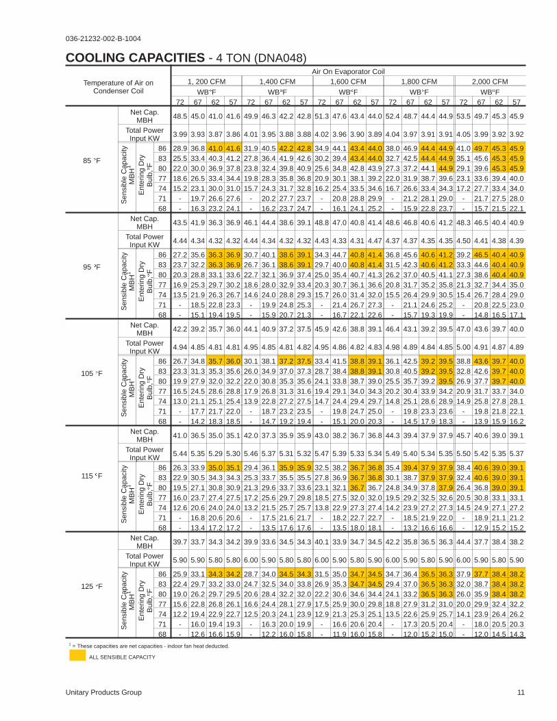
COOLING CAPACITIES - 4 TON (DNA048)
Temperature of Air onCondenser Coil
Air On Evaporator Coil1, 200 CFM 1,400 CFM 1,600 CFM 1,800 CFM 2,000 CFM
WB�F WB�F WB�F WB�F WB�F72 67 62 57 72 67 62 57 72 67 62 57 72 67 62 57 72 67 62 57
85 �F
Net Cap.MBH 48.5 45.0 41.0 41.6 49.9 46.3 42.2 42.8 51.3 47.6 43.4 44.0 52.4 48.7 44.4 44.9 53.5 49.7 45.3 45.9
Total PowerInput KW 3.99 3.93 3.87 3.86 4.01 3.95 3.88 3.88 4.02 3.96 3.90 3.89 4.04 3.97 3.91 3.91 4.05 3.99 3.92 3.92
Sen
sibl
eC
apac
ityM
BH
1
Ent
erin
gD
ryB
ulb,
�F
86 28.9 36.8 41.0 41.6 31.9 40.5 42.2 42.8 34.9 44.1 43.4 44.0 38.0 46.9 44.4 44.9 41.0 49.7 45.3 45.983 25.5 33.4 40.3 41.2 27.8 36.4 41.9 42.6 30.2 39.4 43.4 44.0 32.7 42.5 44.4 44.9 35.1 45.6 45.3 45.980 22.0 30.0 36.9 37.8 23.8 32.4 39.8 40.9 25.6 34.8 42.8 43.9 27.3 37.2 44.1 44.9 29.1 39.6 45.3 45.977 18.6 26.5 33.4 34.4 19.8 28.3 35.8 36.8 20.9 30.1 38.1 39.2 22.0 31.9 38.7 39.6 23.1 33.6 39.4 40.074 15.2 23.1 30.0 31.0 15.7 24.3 31.7 32.8 16.2 25.4 33.5 34.6 16.7 26.6 33.4 34.3 17.2 27.7 33.4 34.071 - 19.7 26.6 27.6 - 20.2 27.7 23.7 - 20.8 28.8 29.9 - 21.2 28.1 29.0 - 21.7 27.5 28.068 - 16.3 23.2 24.1 - 16.2 23.7 24.7 - 16.1 24.1 25.2 - 15.9 22.8 23.7 - 15.7 21.5 22.1
95 �F
Net Cap.MBH 43.5 41.9 36.3 36.9 46.1 44.4 38.6 39.1 48.8 47.0 40.8 41.4 48.6 46.8 40.6 41.2 48.3 46.5 40.4 40.9
Total PowerInput KW 4.44 4.34 4.32 4.32 4.44 4.34 4.32 4.32 4.43 4.33 4.31 4.47 4.37 4.37 4.35 4.35 4.50 4.41 4.38 4.39
Sen
sibl
eC
apac
ityM
BH
1
Ent
erin
gD
ryB
ulb,
�F
86 27.2 35.6 36.3 36.9 30.7 40.1 38.6 39.1 34.3 44.7 40.8 41.4 36.8 45.6 40.6 41.2 39.2 46.5 40.4 40.983 23.7 32.2 36.3 36.9 26.7 36.1 38.6 39.1 29.7 40.0 40.8 41.4 31.5 42.3 40.6 41.2 33.3 44.6 40.4 40.980 20.3 28.8 33.1 33.6 22.7 32.1 36.9 37.4 25.0 35.4 40.7 41.3 26.2 37.0 40.5 41.1 27.3 38.6 40.4 40.977 16.9 25.3 29.7 30.2 18.6 28.0 32.9 33.4 20.3 30.7 36.1 36.6 20.8 31.7 35.2 35.8 21.3 32.7 34.4 35.074 13.5 21.9 26.3 26.7 14.6 24.0 28.8 29.3 15.7 26.0 31.4 32.0 15.5 26.4 29.9 30.5 15.4 26.7 28.4 29.071 - 18.5 22.8 23.3 - 19.9 24.8 25.3 - 21.4 26.7 27.3 - 21.1 24.6 25.2 - 20.8 22.5 23.068 - 15.1 19.4 19.5 - 15.9 20.7 21.3 - 16.7 22.1 22.6 - 15.7 19.3 19.9 - 14.8 16.5 17.1
105 �F
Net Cap.MBH 42.2 39.2 35.7 36.0 44.1 40.9 37.2 37.5 45.9 42.6 38.8 39.1 46.4 43.1 39.2 39.5 47.0 43.6 39.7 40.0
Total PowerInput KW 4.94 4.85 4.81 4.81 4.95 4.85 4.81 4.82 4.95 4.86 4.82 4.83 4.98 4.89 4.84 4.85 5.00 4.91 4.87 4.89
Sen
sibl
eC
apac
ityM
BH
1
Ent
erin
gD
ryB
ulb,
�F
86 26.7 34.8 35.7 36.0 30.1 38.1 37.2 37.5 33.4 41.5 38.8 39.1 36.1 42.5 39.2 39.5 38.8 43.6 39.7 40.083 23.3 31.3 35.3 35.6 26.0 34.9 37.0 37.3 28.7 38.4 38.8 39.1 30.8 40.5 39.2 39.5 32.8 42.6 39.7 40.080 19.9 27.9 32.0 32.2 22.0 30.8 35.3 35.6 24.1 33.8 38.7 39.0 25.5 35.7 39.2 39.5 26.9 37.7 39.7 40.077 16.5 24.5 28.6 28.8 17.9 26.8 31.3 31.6 19.4 29.1 34.0 34.3 20.2 30.4 33.9 34.2 20.9 31.7 33.7 34.074 13.0 21.1 25.1 25.4 13.9 22.8 27.2 27.5 14.7 24.4 29.4 29.7 14.8 25.1 28.6 28.9 14.9 25.8 27.8 28.171 - 17.7 21.7 22.0 - 18.7 23.2 23.5 - 19.8 24.7 25.0 - 19.8 23.3 23.6 - 19.8 21.8 22.168 - 14.2 18.3 18.5 - 14.7 19.2 19.4 - 15.1 20.0 20.3 - 14.5 17.9 18.3 - 13.9 15.9 16.2
115 �F
Net Cap.MBH 41.0 36.5 35.0 35.1 42.0 37.3 35.9 35.9 43.0 38.2 36.7 36.8 44.3 39.4 37.9 37.9 45.7 40.6 39.0 39.1
Total PowerInput KW 5.44 5.35 5.29 5.30 5.46 5.37 5.31 5.32 5.47 5.39 5.33 5.34 5.49 5.40 5.34 5.35 5.50 5.42 5.35 5.37
Sen
sibl
eC
apac
ityM
BH
1
Ent
erin
gD
ryB
ulb,
�F
86 26.3 33.9 35.0 35.1 29.4 36.1 35.9 35.9 32.5 38.2 36.7 36.8 35.4 39.4 37.9 37.9 38.4 40.6 39.0 39.183 22.9 30.5 34.3 34.3 25.3 33.7 35.5 35.5 27.8 36.9 36.7 36.8 30.1 38.7 37.9 37.9 32.4 40.6 39.0 39.180 19.5 27.1 30.8 30.9 21.3 29.6 33.7 33.6 23.1 32.1 36.7 36.7 24.8 34.9 37.8 37.9 26.4 36.8 39.0 39.177 16.0 23.7 27.4 27.5 17.2 25.6 29.7 29.8 18.5 27.5 32.0 32.0 19.5 29.2 32.5 32.6 20.5 30.8 33.1 33.174 12.6 20.6 24.0 24.0 13.2 21.5 25.7 25.7 13.8 22.9 27.3 27.4 14.2 23.9 27.2 27.3 14.5 24.9 27.1 27.271 - 16.8 20.6 20.6 - 17.5 21.6 21.7 - 18.2 22.7 22.7 - 18.5 21.9 22.0 - 18.9 21.1 21.268 - 13.4 17.2 17.2 - 13.5 17.6 17.6 - 13.5 18.0 18.1 - 13.2 16.6 16.6 - 12.9 15.2 15.2
125 �F
Net Cap.MBH 39.7 33.7 34.3 34.2 39.9 33.6 34.5 34.3 40.1 33.9 34.7 34.5 42.2 35.8 36.5 36.3 44.4 37.7 38.4 38.2
Total PowerInput KW 5.90 5.90 5.80 5.80 6.00 5.90 5.80 5.80 6.00 5.90 5.80 5.90 6.00 5.90 5.80 5.90 6.00 5.90 5.80 5.90
Sen
sibl
eC
apac
ityM
BH
1
Ent
erin
gD
ryB
ulb,
�F
86 25.9 33.1 34.3 34.2 28.7 34.0 34.5 34.3 31.5 35.0 34.7 34.5 34.7 36.4 36.5 36.3 37.9 37.7 38.4 38.283 22.4 29.7 33.2 33.0 24.7 32.5 34.0 33.8 26.9 35.3 34.7 34.5 29.4 37.0 36.5 36.3 32.0 38.7 38.4 38.280 19.0 26.2 29.7 29.5 20.6 28.4 32.2 32.0 22.2 30.6 34.6 34.4 24.1 33.2 36.5 36.3 26.0 35.9 38.4 38.277 15.6 22.8 26.8 26.1 16.6 24.4 28.1 27.9 17.5 25.9 30.0 29.8 18.8 27.9 31.2 31.0 20.0 29.9 32.4 32.274 12.2 19.4 22.9 22.7 12.5 20.3 24.1 23.9 12.9 21.3 25.3 25.1 13.5 22.6 25.9 25.7 14.1 23.9 26.4 26.271 - 16.0 19.4 19.3 - 16.3 20.0 19.9 - 16.6 20.6 20.4 - 17.3 20.5 20.4 - 18.0 20.5 20.368 - 12.6 16.6 15.9 - 12.2 16.0 15.8 - 11.9 16.0 15.8 - 12.0 15.2 15.0 - 12.0 14.5 14.3
1 = These capacities are net capacities - indoor fan heat deducted.
ALL SENSIBLE CAPACITY

12 Unitary Products Group
036-21232-002-B-1004
COOLING CAPACITIES - 5 TON (DNA060)
Temperature of Air onOutdoor Coil
Air On Indoor Coil1500 CFM 1750 CFM 2000 CFM 2250 CFM 2500 CFM
WB�F WB�F WB�F WB�F WB�F72 67 62 57 72 67 62 57 72 67 62 57 72 67 62 57 72 67 62 57
85 °F
Net CapMBH 60.3 56.2 52.0 51.1 62.4 58.1 53.8 52.9 64.4 60.0 55.5 54.6 65.4 60.9 56.4 55.5 66.5 61.8 57.3 56.3
Total PowerInput KW 5.67 5.58 5.48 5.50 5.80 5.71 5.61 5.63 5.93 5.83 5.73 5.75 6.11 6.01 5.91 5.93 6.30 6.20 6.09 6.11
Sen
sibl
eC
apac
ityM
BH
1
Ent
erin
gD
ryB
ulb,
�F
86 39.5 47.7 52.0 51.1 43.5 52.3 53.8 52.9 47.5 56.9 55.5 54.6 50.9 59.4 56.4 55.5 54.3 61.8 57.3 56.383 35.2 43.4 50.6 50.9 38.4 47.2 53.1 52.7 41.6 51.0 55.5 54.6 44.3 54.1 56.4 55.5 46.9 57.2 57.3 56.380 31.0 39.1 46.4 46.6 33.4 42.2 50.0 50.2 35.8 45.2 53.6 53.9 37.6 47.5 55.4 55.1 39.4 49.8 57.3 56.377 26.7 34.8 42.1 42.3 28.3 37.1 44.9 45.2 30.0 39.4 47.8 48.1 31.0 40.9 48.8 48.5 32.0 42.3 49.8 48.974 22.4 30.5 37.8 38.0 23.3 32.0 39.9 40.1 24.2 33.6 42.0 42.2 24.3 34.2 42.2 41.8 24.5 34.9 42.4 41.471 - 26.3 33.5 33.8 - 27.0 34.8 35.1 - 27.7 36.1 36.4 - 27.6 35.5 35.2 17.1 27.4 34.9 34.068 - 22.0 29.3 29.5 - 21.9 29.8 30.0 - 21.9 30.3 30.6 - 20.9 28.9 28.5 9.6 20.0 27.5 26.5
95 °F
Net CapMBH 57.6 53.0 49.0 48.5 59.5 54.7 50.7 50.1 61.5 56.5 52.3 51.7 62.4 57.3 53.1 52.4 63.3 58.1 53.9 53.2
Total PowerInput KW 6.14 6.11 5.96 6.01 6.30 6.27 6.11 6.16 6.45 6.42 6.26 6.32 6.62 6.59 6.43 6.49 6.80 6.76 6.60 6.65
Sen
sibl
eC
apac
ityM
BH
1
Ent
erin
gD
ryB
ulb,
�F
86 37.6 46.8 49.0 48.5 41.5 51.4 50.7 50.1 45.3 56.0 52.3 51.7 48.6 57.1 53.1 52.4 51.8 58.1 53.9 53.283 33.3 42.5 48.6 48.2 36.4 46.4 50.5 50.0 39.5 50.2 52.3 51.7 41.9 53.1 53.1 52.4 44.4 56.1 53.9 53.280 29.1 38.3 44.4 43.9 31.4 41.3 47.9 47.4 33.7 44.3 51.4 50.9 35.3 46.5 52.6 52.1 36.9 48.6 53.9 53.277 24.8 34.0 40.1 39.7 26.3 36.2 42.8 42.4 27.8 38.5 45.5 45.1 28.7 39.8 46.0 45.4 29.5 41.2 46.4 45.774 20.5 29.7 35.8 35.4 21.3 31.2 37.8 37.3 22.0 32.7 39.7 39.2 22.0 33.2 39.3 38.8 22.0 33.7 38.9 38.371 - 25.4 31.5 31.1 - 26.1 32.7 32.3 - 26.8 33.9 33.4 - 26.6 32.7 32.1 - 26.3 31.5 30.868 - 21.2 27.2 26.8 - 21.1 27.6 27.2 - 21.0 28.0 27.6 - 19.9 26.0 25.5 - 18.8 24.0 23.4
105 °F
Net CapMBH 53.0 48.8 45.0 42.7 55.0 50.7 46.8 44.3 57.1 52.5 48.5 45.9 57.6 53.1 49.0 46.4 58.2 53.6 49.5 46.9
Total PowerInput KW 6.85 6.74 6.64 6.64 6.99 6.88 6.78 6.78 7.14 7.03 6.93 6.92 7.34 7.22 7.12 7.12 7.54 7.42 7.31 7.31
Sen
sibl
eC
apac
ityM
BH
1
Ent
erin
gD
ryB
ulb,
�F
86 36.1 45.1 45.0 42.7 39.9 48.7 46.8 44.3 43.7 52.3 48.5 45.9 46.9 53.0 49.0 46.4 50.1 53.6 49.5 46.983 31.8 40.8 44.8 42.6 34.9 44.6 46.7 44.2 37.9 48.4 48.5 45.9 40.3 50.5 49.0 46.4 42.6 52.6 49.5 46.980 27.6 36.5 41.5 39.4 29.8 39.5 44.9 42.6 32.1 42.5 48.3 45.8 33.6 44.6 48.9 46.3 35.2 46.6 49.5 46.977 23.3 32.2 37.2 35.1 24.8 34.5 39.8 37.5 26.3 36.7 42.4 40.0 27.0 37.9 42.2 39.7 27.7 39.2 42.0 39.474 19.0 28.0 32.9 30.8 19.7 29.4 34.8 32.5 20.4 30.9 36.6 34.2 20.3 31.3 35.6 33.1 20.3 31.7 34.6 32.071 - 23.7 28.6 26.5 - 24.4 29.7 27.4 - 25.0 30.8 28.3 - 24.6 29.0 26.4 - 24.2 27.1 24.568 - 19.4 24.4 22.3 - 19.3 24.6 22.4 - 19.2 24.9 22.5 - 18.0 22.3 19.8 - 16.8 19.7 17.1
115 °F
Net CapMBH 48.4 44.7 41.0 36.9 50.5 46.6 42.8 38.5 52.6 48.6 44.6 40.1 52.9 48.8 44.9 40.3 53.2 49.1 45.1 40.5
Total PowerInput KW 7.56 7.37 7.33 7.27 7.69 7.50 7.46 7.40 7.82 7.63 7.59 7.53 8.05 7.85 7.81 7.75 8.28 8.08 8.03 7.97
Sen
sibl
eC
apac
ityM
BH
1
Ent
erin
gD
ryB
ulb,
�F
86 34.6 43.3 41.0 36.9 38.4 45.9 42.8 38.5 42.2 48.6 44.6 40.1 45.2 48.8 44.9 40.3 48.3 49.1 45.1 40.583 30.3 39.1 41.0 36.9 33.3 42.8 42.8 38.5 36.3 46.5 44.6 40.1 38.6 47.8 44.9 40.3 40.8 49.1 45.1 40.580 26.1 34.8 38.6 34.8 28.3 37.7 41.9 37.8 30.5 40.7 45.2 40.7 31.9 42.6 45.1 40.6 33.4 44.6 45.1 40.577 21.8 30.5 34.3 30.5 23.2 32.7 36.8 32.7 24.7 34.9 39.3 34.9 25.3 36.0 38.5 34.0 25.9 37.1 37.7 33.174 17.5 26.2 30.0 26.3 18.2 27.6 31.8 27.7 18.8 29.0 33.5 29.1 18.7 29.4 31.9 27.4 18.5 29.7 30.2 25.671 - 22.0 25.8 22.0 - 22.6 26.7 22.6 - 23.2 27.7 23.2 - 22.7 25.2 20.7 - 22.2 22.8 18.268 - 17.7 21.5 17.7 - 17.5 21.7 17.6 - 17.4 21.8 17.4 - 16.1 18.6 14.1 - 14.8 15.3 10.7
125 °F
Net CapMBH 43.8 40.5 37.1 31.1 46.0 42.6 38.9 32.7 48.2 44.6 40.7 34.3 48.2 44.6 40.8 34.2 48.2 44.6 40.8 34.2
Total PowerInput KW 8.30 8.00 8.00 7.90 8.40 8.10 8.10 8.00 8.50 8.20 8.20 8.10 8.80 8.50 8.50 8.40 9.00 8.70 8.70 8.60
Sen
sibl
eC
apac
ityM
BH
1
Ent
erin
gD
ryB
ulb,
�F
86 33.1 41.6 37.1 31.1 36.8 43.2 38.9 32.7 40.6 44.8 40.7 34.3 43.5 44.7 40.8 34.2 46.5 44.6 40.8 34.283 28.8 37.3 37.3 31.2 31.8 41.0 39.0 32.7 34.7 44.7 40.7 34.3 36.9 45.2 40.8 34.2 39.1 45.6 40.8 34.280 24.5 33.0 35.7 30.2 26.7 36.0 38.9 32.9 28.9 38.9 42.0 35.6 30.3 40.7 41.4 34.9 31.6 42.5 40.8 34.277 20.3 28.8 31.4 26.0 21.7 30.9 33.8 27.9 23.1 33.1 36.2 29.8 23.6 34.1 34.8 28.3 24.2 35.1 33.3 26.874 16.0 24.5 27.1 21.7 16.6 25.9 28.8 22.8 17.2 27.2 30.4 24.0 17.0 27.4 28.1 21.6 16.7 27.6 25.9 19.371 - 20.2 22.9 17.4 - 20.8 23.7 17.8 - 21.4 24.6 18.2 - 20.8 21.5 15.0 - 20.2 18.4 11.968 - 15.9 18.6 13.1 - 15.8 18.7 12.7 - 15.6 18.7 12.3 - 14.2 14.8 8.2 - 12.7 10.9 4.4
1 = These capacities are net capacities - indoor fan heat deducted.
ALL SENSIBLE CAPACITY

Unitary Products Group 13
036-21232-002-B-1004
SIDE SUPPLY AIR BLOWER PERFORMANCE
MODELNO.DNA
MOTORSPEED
EXTERNAL STATIC PRESSURE - IWG.10 .20 .30 .40 .50 .60 .70 .80 .90 1.00 1.10
CF
M
WA
TT
S
CF
M
WA
TT
S
CF
M
WA
TT
S
CF
M
WA
TT
S
CF
M
WA
TT
S
CF
M
WA
TT
S
CF
M
WA
TT
S
CF
M
WA
TT
S
CF
M
WA
TT
S
CF
M
WA
TT
S
CF
M
WA
TT
S
018HI
MEDLOW
---
---
---
---
---
---
--
721
--
255
--
651
--
241
--
581
--
226
-706511
-280212
-588
-
-257
-
688470
-
454234
-
568--
436--
---
---
024HI
MEDLOW
--
998
--
372
--
906
--
333
-999813
-353294
-944721
-338255
-865651
-319241
-785
-
-299
-
929706
-
491280
-
809--
473--
688--
454--
---
---
---
---
030HI
MEDLOW
-1110998
-383372
-1055906
-368333
-999813
-353294
1200944
-
560338
-
1110865
-
537319
-
1019785
-
514299
-
929--
491--
809--
473--
---
---
---
---
---
---
036HI
MEDLOW
--
1384
--
625
--
1336
--
605
-14831287
-682584
-14201239
-655564
-13411167
-625537
144712621094
754596509
136011831022
722566482
12641075903
692534460
1169966
-
663501
-
1073--
633--
977--
603--
042HI
MEDLOW
-16101384
-735625
-15471336
-708605
170514831287
847682584
162214201239
818655564
153513411167
786625537
144712621094
754596509
13601183
-
722566
-
12641075
-
692534
-
1169--
663--
1073--
633--
---
---
048,060HI
MEDLOW
---
---
---
---
--
1893
--
945
209419551815
1152987903
201018701730
1117947868
190817851640
1082914819
182016901545
1040877780
148014001290
926773695
137012901180
890744662
122011601060
845708625
---
---
NOTE: Above data includes allowances for a dry evaporator coil , gas heat exchanger and no filters. For additional pressure drops, refer to the “Additional Static Pressure Resistance” table.
208 volts
MODELNO.DNA
MOTORSPEED
EXTERNAL STATIC PRESSURE - IWG.10 .20 .30 .40 .50 .60 .70 .80 .90 1.00 1.10
CF
M
WA
TT
S
CF
M
WA
TT
S
CF
M
WA
TT
S
CF
M
WA
TT
S
CF
M
WA
TT
S
CF
M
WA
TT
S
CF
M
WA
TT
S
CF
M
WA
TT
S
CF
M
WA
TT
S
CF
M
WA
TT
S
CF
M
WA
TT
S
018HI
MEDLOW
--
743
--
243
--
700
--
235
--
657
--
226
--
614
--
218
--
549
--
207
-695483
-263195
-615
-
-246
-
-509
-
-226
-
608--
358--
465--
326--
---
---
024HI
MEDLOW
-994743
-333243
-947700
-321235
-901657
-309226
-854614
-297218
-774
-
-280
-
984695
-
443263
-
894615
-
422246
-
751--
390--
608--
358--
---
---
---
---
030HI
MEDLOW
-994
-
-333
-
-947
-
-321
-
1238901
-
504309
-
1165854
-
484297
-
1075774
-
463280
-
984--
443--
894--
422--
751--
390--
---
---
---
---
---
---
036HI
MEDLOW
-14321191
-650527
-13811149
-628510
-13301107
-605494
-12791065
-583477
146512101009
712556459
13901140952
685529441
13151071
-
657502
-
1204977
-
623477
-
1093--
588--
982--
554--
---
---
042HI
MEDLOW
-14321191
-650527
168113811149
797628510
161013301107
768605494
154012791065
740583477
14651210
-
712556
-
13901140
-
685529
-
1315--
657--
1204--
623--
1093--
588--
---
---
---
---
048,060HI
MEDLOW
---
---
---
---
--
1672
--
841
190817731610
1023894804
183217261542
982869773
17371674
-
938852
-
16561613
-
889832
-
13481339
-
789731
-
1252--
754--
---
---
---
---
NOTE: Above data includes allowances for a dry evaporator coil , gas heat exchanger and no filters. For additional pressure drops, refer to the “Additional Static Pressure Resistance” table.
230, 460 and 575 volts
14 Unitary Products Group
036-21232-002-B-1004
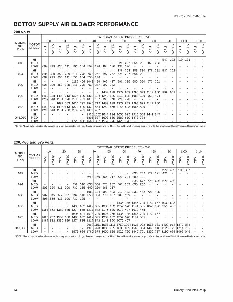
BOTTOM SUPPLY AIR BLOWER PERFORMANCE
MODELNO.DNA
MOTORSPEED
EXTERNAL STATIC PRESSURE - IWG.10 .20 .30 .40 .50 .60 .70 .80 .90 1.00 1.10
CF
M
WA
TT
S
CF
M
WA
TT
S
CF
M
WA
TT
S
CF
M
WA
TT
S
CF
M
WA
TT
S
CF
M
WA
TT
S
CF
M
WA
TT
S
CF
M
WA
TT
S
CF
M
WA
TT
S
CF
M
WA
TT
S
CF
M
WA
TT
S
018HI
MEDLOW
--
669
--
219
--
630
--
211
--
591
--
204
--
553
--
196
--
494
--
186
-625435
-237176
-554
-
-221
-
-458
-
-203
-
547--
322--
419--
293--
---
---
024HI
MEDLOW
-895669
-300219
-853630
-289211
-811591
-278204
-769553
-267196
-697
-
-252
-
886625
-
398237
-
805554
-
380221
-
676--
351--
547--
322--
---
---
---
---
030HI
MEDLOW
-895
-
-300
-
-853
-
-289
-
1115811
-
454278
-
1049769
-
436267
-
967697
-
417252
-
886--
398--
805--
380--
676--
351--
---
---
---
---
---
---
036HI
MEDLOW
-14821239
-628510
-14281184
-613496
-13741130
-599481
-13201075
-584467
14581242998
688556448
13771163922
663528428
12951085
-
639500
-
1147961
-
600474
-
999--
561--
---
---
---
---
042HI
MEDLOW
-14821239
-628510
168714281184
763613496
161413741130
737599481
154013201075
712584467
14581242
-
688556
-
13771163
-
663528
-
12951085
-
639500
-
1147--
600--
---
---
---
---
---
---
048,060HI
MEDLOW
---
---
---
---
--
1725
--
850
192818051660
1032837807
184416931557
994859776
163615801428
923819728
15151473
-
888788
-
1441--
849--
---
---
---
---
---
---
NOTE: Above data includes allowances for a dry evaporator coil , gas heat exchanger and no filters. For additional pressure drops, refer to the “Additional Static Pressure Resistance” table.
208 volts
MODELNO.DNA
MOTORSPEED
EXTERNAL STATIC PRESSURE - IWG.10 .20 .30 .40 .50 .60 .70 .80 .90 1.00 1.10
CF
M
WA
TT
S
CF
M
WA
TT
S
CF
M
WA
TT
S
CF
M
WA
TT
S
CF
M
WA
TT
S
CF
M
WA
TT
S
CF
M
WA
TT
S
CF
M
WA
TT
S
CF
M
WA
TT
S
CF
M
WA
TT
S
CF
M
WA
TT
S
018HI
MEDLOW
---
---
---
---
---
---
--
649
--
230
--
586
--
217
--
523
--
204
-635460
-252191
-529
-
-231
-
620423
-
409--
511--
392--
---
---
024HI
MEDLOW
--
898
--
335
--
815
--
300
-899732
-318265
-850649
-304230
-778586
-287217
-707
-
-269
-
836635
-
442252
-
728--
425--
620--
409--
---
---
---
---
030HI
MEDLOW
-999898
-345335
-949815
-331300
-899732
-318265
1080850
-
504304
-
999778
-
483287
-
917707
-
463269
-
836--
442--
728--
425--
---
---
---
---
---
---
036HI
MEDLOW
--
1387
--
582
--
1330
--
569
-14901274
-652555
-14221217
-625542
-13391148
-602520
143612571079
735578497
134511741010
705555475
11891049
-
667526
-
1032953
-
628497
-
---
---
---
---
042HI
MEDLOW
-16251387
-707582
-15571330
-680569
169514901274
821652555
161814221217
796625542
152713391148
766602520
143612571079
735578497
13451174
-
705555
-
1189--
667--
---
---
---
---
---
---
048,060HI
MEDLOW
---
---
---
---
--
1878
--
924
206819281786
1151998875
198518061655
1118935838
175816801525
1034889786
162515601440
992854761
155514481336
961816717
140813251196
914773679
127012141097
872735646
---
---
NOTE: Above data includes allowances for a dry evaporator coil , gas heat exchanger and no filters. For additional pressure drops, refer to the “Additional Static Pressure Resistance” table.
230, 460 and 575 volts

Unitary Products Group 15
036-21232-002-B-1004
DESCRIPTION
RESISTANCE, IWG
CFM
500 600 700 800 900 1,000 1,100 1,200 1,300 1,400 1,500 1,600 1,700 1,800 1,900 2,000
Wet Evaporator coil .01 .01 .01 .02 .03 .04 .05 .06 .07 .08 .09 .09 - - - -
Economizer .00 .00 .00 .01 .01 .01 .01 .02 .03 .04 .05 .06 - - - -
Filter/Frame Kit .01 .02 .04 .06 .08 .10 .13 .16 .17 .18 .19 .20 - - - -
NOTE: 1. Deduct these resistance values from the available external static pressure shown in the respective Blower Performance Table.
2. The pressure thru the economizer is greater for 100% outdoor air then for 100% return air. If the resistance of the return air duct system is less then 0.25 IWG, the unit will deliverless CFM during full economizer operation.
ADDITIONAL STATIC PRESSURE RESISTANCE
DESCRIPTION
RESISTANCE, IWG
CFM
500 600 700 800 900 1,000 1,100 1,200 1,300 1,400 1,500 1,600 1,700 1,800 1,900 2,000
Wet Evaporator coil - - - - - - - .03 .04 .05 .06 .07 .07 .08 .09 .09
Economizer - - - - - - - .02 .02 .03 .03 .04 .04 .04 .05 .05
Filter/Frame Kit - - - - - - - .04 .05 .05 .06 .07 .08 .09 .10 .11
NOTE: 1. Deduct these resistance values from the available external static pressure shown in the respective Blower Performance Table.
2. The pressure thru the economizer is greater for 100% outdoor air then for 100% return air. If the resistance of the return air duct system is less then 0.25 IWG, the unit will deliverless CFM during full economizer operation.
4 AND 5 TON (DNA048 AND DNA060)
1-1/2 THRU 3-1/2 TON (DNA048 AND DNA060)

16 Unitary Products Group
036-21232-002-B-1004
MODELDNA
POWERSUPPLY
VOLTAGELIMITATIONS1 COMPRESSOR COND.
FANMOTOR,
FLA
SUPPLYAIR
BLOWERMOTOR,
FLA
MIN.CIRCUIT
AMP.
MAX.FUSESIZE,
AMPS2
MAX.HACR
BREAKERSIZE,AMPS
UNITPOWERFACTOR
TRANSFORMERSIZE (VA) 3
MIN. MAX. RLA LRA
018 208/230-1-60 187 253 9.0 48.0 1.1 2.2 14.5 20 20 .96 40024 208/230-1-60 187 253 11.5 60.0 1.1 2.2 17.7 25 25 .96 40030 208/230-1-60 187 253 14.7 73.0 1.1 2.2 21.7 30 30 .96 40036 208/230-1-60 187 253 17.3 94.0 1.1 3.5 26.2 35 35 .96 40042 208/230-1-60 187 253 20.5 120.0 1.1 3.5 30.2 40 40 .96 40048 208/230-1-60 187 253 24.4 140.0 1.3 7.0 38.8 50 50 .96 40060 208/230-1-60 187 253 28.9 175.0 1.3 7.0 44.4 60 60 .96 40036 208/230-3-60 187 253 10.9 78.0 1.1 3.5 18.2 25 25 .96 75042 208/230-3-60 187 253 14.1 110.0 1.1 3.5 22.2 30 30 .96 75048 208/230-3-60 187 253 14.1 105 1.3 7.0 25.9 35 35 .96 75060 208/230-3-60 187 253 15.5 125 1.3 7.0 29.5 40 40 .96 75036 460-3-60 414 504 5.8 40.0 0.6 1.8 9.6 15 15 .96 75042 460-3-60 414 504 7.1 54.0 0.6 1.8 11.2 15 15 .96 75048 460-3-60 414 504 7.1 55.0 0.7 3.5 13.1 20 20 .96 75060 460-3-60 414 504 8.9 66.5 0.7 3.5 15.4 20 20 .96 75036 575-3-60 518 630 4.5 32.0 0.4 1.5 7.5 15 15 .96 75042 575-3-60 518 630 5.8 44.0 0.4 1.5 9.1 15 15 .96 75048 575-3-60 518 630 5.7 45.0 0.6 2.8 10.5 15 15 .96 75060 575-3-60 518 630 7.1 50.0 0.6 2.8 12.3 15 15 .96 75
Note; Electrical data based on 104°F outdoor air ambient temperature.1 = Rated in accordance with ARI Standard 110, utilization range “A”.2 = Dual element, time delay type.3 = If economizer or motorized damper are to be used, 75 VA is required. Refer to price pages for future details.
FIELD WIRING DIAGRAM�
�
�
�
�
�
��
�
�
24 VOLT TRANSFORMER
UNIT TERMINAL STRIPTHERMOSTAT
CONTROL WIRING
PROGRAMABLETHERMOSTAT ONLY
** = Minimum wire size of 18 AWGwire should be used for all field
installed 24 volt wire.
**NOTE:HEAT ANTICIPATORSHOULD BE SET AT 0.35AMPS FOR ALL MODELS.
REFER TO ELECTRICALDATA TABLES TO SIZE
THE DISCONNECT
ELECTRICAL DATA
REFER TO ELECTRICALDATA TABLES TO SIZE
THE DISCONNECT
POWER WIRING

Unitary Products Group 17
036-21232-002-B-1004
CLEARANCES(Minimum)
Front 36"
Back 0"
Left Side (Filter Access) 24"
Right Side 12"
Below Unit1 0"
Above Unit2 36" (For CondenserAir Discharge)
1 Units may be installed on combustible floors made from wood or class A,B or C roof covering material.
2 Units must be installed outdoors. Overhanging structures or shrubsshould not obstruct condenser air discharge outlet.
NOTE:A 1" clearance must be provided between any combustible materialand the supply air ductwork.
The products of combustion must not be allowed to accumulatewithin a confined space and recirculate.
UNIT DIMENSIONS
B A
���
GAS SUPPLY ���“ DIA. HOLE
(��" NPTI CONNECTION)
CONDENSER COIL
����
����
����
LOW VOLTAGE CONN.���“ DIA. KNOCKOUT x �
�" HOLE
HIGH VOLTAGE CONN.��“ DIA. KNOCKOUT
VENT AIR OUTLET HOOD
FRONT
COMBUSTION AIRINLET LOUVERS
GAS/ELECTRIC CONTROLSERVICE ACCESS
COMPARTMENT PANEL
BLOWERSERVICE ACCESS
COMPARTMENT PANEL
(OVERALL)
(OVERALL)
(OVERALL)
���
����
��
���
REFRIGERANTCONNECTIONS
GAS SUPPLY ���“ DIA. KNOCKOUT
(��" NPTI CONNECTION)
���
All dimensions are in inches. They aresubject to change without notice. Certifieddimensions will be provided upon request.
11
HIGH VOLTAGE CONN.���“ DIA. KNOCKOUT
UNIT CONDENSATECONNECTION �
�“ NPTI(TRAP RECOMMENDED)
���
CONDENSATEDRAIN �
�“ NPTI
GAS SUPPLY ���“ DIA. KNOCKOUT
(��" NPTI CONNECTION)
LOW VOLTAGE CONN.��“ DIA. KNOCKOUT
FRONT
����
HIGH VOLTAGECONN. ����“ DIA.
KNOCKOUT
SIDE RETURNAIR OPENING
REAR
SIDE SUPPLYAIR OPENING
BOTTOM SUPPLYAIR OPENING
CONDENSERCOIL
BOTTOM RETURNAIR OPENING
���
4
����
����
���15
�����
15
���
15
����
���
����
����
���
���
���
UNITSIZE
DIMENSION
“A” “B”
018 THRU 042 ���� ��
��
048 AND 060 ���� ��
��
���
6
����
���

18 Unitary Products Group
036-21232-002-B-1004
TYPICAL APPLICATIONS
� � � � � � � � � � � � � � �
� � � � � � � � � � � � � �
� � � � � � � � � � � � � � � � �
� � � �
� � � � � � � � � �
� � � � � �
� � � � � � � � � � � �
� � � � � � � �
� � � �
� � � � � � � � �
� � � �
� � � � � � � � � �
� � � � �
� � � � � � � �
� � � � � � � � � � � �
TYPICAL SLAB ON GROUND INSTALLATION
� � � � � �
� � � � � � � � � � � �
� � � � � �
� � � � � � � �
� � � � � � �
� � � � � � �
� � � � � �
� � � �
� � � � � �
� � � � � �
� � � �
� � � � � � � � � �
� � � � � � � � � �
� � � � � � � � � � � � � �
� � � � � � � �
� � � �
� � � � � � � � �
� � � �
TYPICAL ROOF CURB INSTALLATION
4�8�-�1�1�/3�2�
2�1�3�2�-�1�/8�
1�5�-�1�/4�2524
����
CENTER OF GRAVITYFRONTOF
UNIT
“C”
“D”
“B”
“A”
UNITSIZE
SHIPPINGWEIGHT
(lbs.)
OPERAT-ING
WEIGHT(lbs.)
OPERATING CORNERWEIGHTS
(location, lbs.)ECONI-MIZER(lbs.)
ROOFCURB
(inch/lbs.)“A” “B” “C” “D”
018 365 360 91 88 89 92
40 8" / 7014" / 75
024 365 360 91 88 89 92
030 395 390 98 95 96 99
036 400 395 100 96 98 101
042 415 410 104 100 101 105
048 475 470 119 115 116 120
060 480 475 120 116 117 122
ROOF CURBINSTALLATION
REAR DUCT
SLAB ON GROUNDINSTALLATION
ROOF CURBINSTALLATIONBOTTOM DUCT
����

Unitary Products Group 19
036-21232-002-B-1004
ROOF CURB DIMENSIONS(8" roof curb also available)
FRONT
����
���
���� 451/8
����
1
1
WOOD NAILER
4
INSULATEDPANELS
22
����
14
���
OPENING FORRETURN AIR DUCT
OPENING FORSUPPLY AIR DUCT
RECOMMENDED DUCT SIZE
SUPPLY AIR DUCT ����" x ��
��"
RETURN AIR DUCT ����" x ��
��"
UNIT BASE RAIL
UNIT BASE
WOOD NAILER
8" MIN. ABOVE FINISHED ROOF
CURB FRAME
COUNTERFLASHING
INSULATION
CANT STRIP
ROOF DECK AND ROOFING MATERIAL
INSULATION AND ROOFING MATERIAL
��" x 1" WIDE GASKETING FOR CURB FRAME
AND ALL DUCT SUPPORT SURFACES
14"
1"
ROOF CURB APPLICATION

20 Unitary Products Group
036-21232-002-B-1004
TYPICAL WIRING DIAGRAM (208/230-1-60 POWER SUPPLY)
TYPICAL WIRING DIAGRAM (208/230-3-60 POWER SUPPLY)
SEEDETAIL
"A"��
�� � �
���� ���
�
�
� ����
��
������ ���
� � � �����������
�
� ����
� � � �����������
�
(See page 22)

Unitary Products Group 21
036-21232-002-B-1004
TYPICAL WIRING DIAGRAM (575-3-60 POWER SUPPLY)
(See page 22)B
(See page 22)B
TYPICAL WIRING DIAGRAM (460-3-60 POWER SUPPLY)

22 Unitary Products Group
036-21232-002-B-1004
(ALTERNATE)
(ALTERNATE)
WIRING DIAGRAM DETAIL “A”(208/230-1-60 POWER SUPPLY) See page 20
TYPICAL WIRING DIAGRAM LEGEND (See pages 20 and 21)
WIRING DIAGRAM DETAIL “B”(460 & 575-3-60 POWER SUPPLY) See page 21
TYPICAL WIRING DIAGRAM NOTES (See pages 20 and 21)

GENERAL DESCRIPTION
Units shall be factory-assembled, single packaged, ElectricCooling/Gas Heating units, designed for outdoor mounted in-stallation. Units shall have minimum SEER ratings of 10.0 andminimum AFUE ratings of 80%. They shall have built in, equalsize, field convertible duct connections for down dischargesupply/return or horizontal discharge supply/return.
The units shall be factory wired, piped, charged with R-22 re-frigerant and factory tested prior to shipment. All unit wiringshall be both numbered and color coded.
All units shall be manufactured in a facility certified to ISO9001 standards, and the cooling performance shall be rated inaccordance with DOE and ARI test procedures. The heatingperformance shall be rated to DOE and GAMA test proce-dures. Units shall be CSA listed and classified to ANSIZ21.47/CAN/CSA 2.3 standards and UL 1995/CAN/CSA No.236-M90 conditions.
UNIT CABINET
1. Unit cabinet shall be constructed of G90 galvanized steel,with exterior surfaces coated with a non-chalking, pow-ered paint finish, certified at 1000 hour salt spray test perASTM-B117 standards.
2. The unit top shall be a single piece “Water Shed” design,with drip edges and no-seam corners to provide optimumwater integrity.
3. Unit shall have a rigidly mounted condenser coil guard toprovide protection from objects and personnel after instal-lation.
4. Indoor blower section shall be insulated with up to 3/4”thick, aluminum, foil faced insulation, fastened to preventinsulation from entering the air stream.
5. Cabinet panels shall be “large” size, easily removable forservicing and maintenance, with built-in lift handles.
6. Unit shall be built on a formed, “Super-Structure” designbase pan, with embossments at critical points to addstrength, rigidity and aid in minimizing sound.
7. Full perimeter base rails shall be provided to assure reli-able transit of equipment, overhead rigging, fork truck ac-cess and proper sealing on roof curb applications. Baserails shall be removable, when required, to lower unitheight.
8. Filters shall be furnished and be accessible through a re-movable access door, sealed air tight.
9. Units vertical discharge and return duct configurationshall be designed to fit between standard 24” O.C. beamswithout modification to building structure, duct work andbase unit.
10. Condensate pan shall be internally sloped and conform toASHARE 62-89 self-draining standards, with 3/4” NPTIcopper, ridged mount connection.
1. Fan shall be direct drive, multi-speed design. Job site se-lected (BHP) brake horse power shall not exceed the mo-tors nameplate horse power rating.
2. Fan wheel shall be double-inlet type with forward-curvedblades, dynamically balanced to operate smoothlythroughout the entire range of operation. Airflow designshall be constant air volume.
3. Bearings shall be sealed and permanently lubricated forlonger life and no maintenance.
4. Fan assembly shall be “Slip Track” (slide-out) design foreasy removal and cleaning.
OUTDOOR (CONDENSER) FAN ASSEMBLY
1. The outdoor fan shall be of the direct-driven propellertype, discharge air vertically, have aluminum blades riv-eted to corrosion resistant steel spider bracket and shallbe statically balanced for smooth operation.
2. The outdoor fan motor shall be totally enclosed with per-manently lubricated bearings and internally protectedagainst overload conditions.
REFRIGERANT COMPONENTS
1. Compressors:
A. Shall be fully hermetic type, direct drive, internally pro-tected with internal high-pressure relief and over tem-perature protection. The hermetic motor shall besuction gas cooled and have a voltage range of + or -10% of the unit nameplate voltage.
B. Shall have internal isolation and sound muffling tominimize vibration and noise, and be externally iso-lated on a dedicated, independent mounting.
2. Coils:
A. Evaporator and condenser coils shall have aluminumplate fins mechanically bonded to seamless internally-enhanced copper tubes with all joints brazed.
B. Evaporator coil shall be of the direct expansion, blow-through design, while condenser coil shall be draw-through design.
3. Refrigerant Circuit and Refrigerant Safety Componentsshall include:
A. Independent fixed-orifice expansion devices.
B. Filter/strainer to eliminate any foreign matter.
Unitary Products Group 23
036-21232-002-B-1004
MECHANICAL SPECIFICATIONSINDOOR (EVAPORATOR) FAN ASSEMBLY
Unitary Products Group5005 Interstate Drive North, Norman, Oklahoma 73069Subject to change without notice. Printed in U.S.A.Copyright � by York International Corporation 2003. All Rights Reserved.
036-21232-002-B-1004Supersedes: 036-21232-002-A-0503
��� ����
������ ������
��������� �����
UNIT OPERATING CHARACTERISTICS
Unit shall be capable of starting and running at 125�F outdoortemperature, exceeding maximum load criteria of ARI Stan-dard 210/240. The compressor, with standard controls, shall becapable of operation down to 45�F outdoor temperature. Ac-cessory low ambient kit shall be available for operation to 0�F.
ELECTRICAL REQUIREMENTS
All unit power wiring shall enter unit cabinet at a single factoryprovided location and be capable of side or bottom entry, tominimize roof penetrations and avoid unit field modifications.Separate side and bottom openings shall be provided for thecontrol wiring.


