
www. .comIMG.803.V13.EN
your reliable partner
Safety brakes

your reliable partner
Specialists for power transmission for more than a century
We safeguard the movements of this world
The Christian Mayr mill-construction business – founded in 1897.
mayr ® power transmission is one of the most traditional and yet most innovative German companies in the field of power transmission. From modest beginnings in the year 1897, the family enterprise from the Allgäu region has developed into world market leader. Today, 550 employees work at the headquarters in Mauerstetten; more than 1000 employees work for the company worldwide.
Unsurpassed - our standard rangemayr ® power transmission offers an extensive variety of torque limiters, safety brakes, backlash-free shaft misalignment compensation couplings and high-quality DC drives. Also when it comes to customer-specific requirements, the company possesses the expertise to develop customized and economical solutions. This is why numerous renowned machine manufacturers trust in holistic solutions by mayr ® power transmission.
Available worldwideWith eight subsidiaries in Germany, sales offices in the USA, France, Great Britain, Italy, Singapore and Switzerland as well as 36 additional country representatives, mayr ®
is available in all important industrial areas, guaranteeing optimum customer service around the globe.
2

your reliable partner
Tradition and innovation –the best of both worlds
Tradition and innovation do not contradict each other - on the contrary. They are the two supporting pillars which have guaranteed stability and reliability for generations. Long-term stability, independence as well as a good reputation and satisfied customers are important values for a family enterprise rich in tradition.
Therefore, we place emphasis on:
● Tested product quality,
● Optimum customer service,
● Comprehensive know-how,
● Global presence,
● Successful innovations and
● Effective cost management
Following our own objective of always offering our customers the technologically most advanced and economical solution, we have been able to gain the trust of many leading industrial companies from all branches and from all over the world as a reliable partner.
Place your trust in our know-how and our more than 50 years of experience in torque limiters, safety brakes and shaft couplings.
3

your reliable partner
Tested quality and reliability
Never compromise on safety
mayr ® products are subject to meticulous quality inspections. These include quality assurance measures during the construction process as well as a comprehensive final inspection. Only the best, tested quality leaves our factory. All products are rigorously tested on calibrated test stands, and adjusted precisely to the requested values. An electronic database in which the measurement values are archived together with the associated serial numbers guarantees 100 % traceability. On request, we confirm the product characteristics with a test protocol.
The certification of our quality management according to DIN EN ISO 9001:2000 confirms the quality-consciousness of our colleagues at every level of the company.
We make no compromises where safety is concerned. Only top products of a perfect quality guarantee that no people are injured or machines damaged in case of malfunctions, collisions and other hazardous situations. The safety of your employees and machines is our motivation to always provide the best and most reliable clutches, couplings or brakes.
mayr ® power transmission holds numerous ground-breaking patents, and is the global market or technological leader for
• application-optimised safety brakes, for example for passenger elevators, stage technology and gravity loaded axes
• torque limiters to protect against expensive overload damage and production losses and
• backlash-free servo couplings.
4

your reliable partner
FunctionROBA-stop® safety brakes are spring applied, electromagnetic safety brakes. These brakes ensure reliable and safe braking of machines and systems in any position in the event of a power switch-off, a power failure or an EMERGENCY STOP.
Overview
RO
BA
-sto
p®-
po
siti
oni
ng b
rake
RO
BA
-sto
p®-h
old
ing
bra
ke
RO
BA
-sto
p® -
tac
ho b
rake
RO
BA
-sto
p® -
pea
k lo
ad b
rake
RO
BA
-sto
p®-M
-po
siti
oni
ng b
rake
RO
BA
-sto
p®-M
-ho
ldin
g b
rake
RO
BA
®-t
op
sto
p®
RO
BA
®-a
lpha
sto
p®
RO
BA
®-s
ervo
sto
p®
RO
BA
®-s
ervo
stop
®fo
r ro
botic
app
licat
ions
RO
BA
®-p
inio
nsto
p
RO
BA
®-l
inea
rsto
p
RO
BA
®-g
uid
esto
p
RO
BA
-sto
p®-s
ilenz
io® d
ual c
ircu
it b
rake
RO
BA
-sto
p®-s
ilenz
io® s
ingl
e ci
rcui
t br
ake
RO
BA
-sto
p®-s
ilenz
io®
wit
h d
oub
le r
oto
r
RO
BA
®-d
isks
top
®
RO
BA
®-d
uplo
sto
p®
RO
BA
®-t
win
sto
p®
RO
BA
®-q
uatr
ost
op
RO
BA
-sto
p®-S
Construction Types we recommend
Suitable Types
Exemplary application areas
General mechanical engineering
Electromotors
Servo drives
Crane construction
Harbour/ship/seawater
Elevator construction
Escalators
Stage construction
Hoists
Mobile devices with low voltage
Medical technology
Robots/handling
Gravity loaded axes
Linear motors
Machine tools
Special characteristics
CSA-certification
ATEX design
Sealed design
Two independent brake circuits
Minimal noise
Brake description page ... 6 6 6 6 7 7 8 9 10 11 12 13 14 15 15 15 16 17 18 19 20
Brake description page ... 6 6 6 6 7 7 8 9 10 11 12 13 14 15 15 15 16 17 18 19 20
On request ROBA-stop® safety brakes can also be delivered with UL approval.
5

➡
➡L
Ø D
your reliable partner
ROBA-stop®-UniversalThe multifunctional all-round safety brake
Performance Characteristics
● Sensitive braking torque adjustment● Simple wear re-adjustment● Designs as positioning brake, holding brake,
tacho brake and peak load brake● Enclosed construction● Simple installation● Class of insulation F● Can be used for 100 % duty cycle● Short switching times
Designs
❑ ROBA-stop®-positioning brake Brake as working brakes from movement and offer high
positioning and repetitive accuracy.
❑ ROBA-stop®-holding brake Achieve very high braking torques and hold drives safely
in position when they are not running.
❑ ROBA-stop®- tacho brakes Feature a centering recess and tapped holes on the back
of the brake for mounting a tacho-generator.
❑ ROBA-stop®-tacho peak load brakes Allow a tacho-generator to be mounted and have a
special armature disk for high friction work.
❑ ROBA-stop®- peak load brakes Have a special, extremely strong armature disk which
allows high friction work.
ROBA-stop® application in a high rack warehouse
For detailed technical data and dimensions, please see catalogue: ROBA-stop® K.800.V_ _._ _
Technical Data and DimensionsSize
2 3 4 5 6 7 8 9 10 11
Braking torque 1)
M [Nm] 1.1 3 6 12 26 50 100 200 400 800
Holding brake M [Nm] – 5 10 22 48 90 180 360 620 1250
Shaft Ø[mm] 6 – 11 8 – 12 10 – 15 10 – 20 15 – 25 20 – 32 25 – 45 25 – 50 25 – 60 30 – 80
Holding brake [mm] – 8 – 12 10 – 15 10 – 20 15 – 25 20 – 32 25 – 45 30 – 50 30 – 60 30 – 80
Brake
Outer Ø D [mm] 59 79 98 114 142 165 199 220 275 360
Length L [mm] 28 30.2 32.2 39.3 43.2 58.2 66.7 74.3 96.3 116.3
Length peak load brake L [mm] – – – – – 68.2 77.7 87.3 116.3 138.3
1) Tolerance +40 % / -20 %
6

your reliable partner
ROBA-stop®-MThe robust, cost-effective motor brake
Performance Characteristics
● Maintenance-free (no re-adjustment)● Simple installation● Completely enclosed brake housing acc.
Protection IP54 or IP65● Class of insulation F● Can be used for 100 % duty cycle● Short switching times
Designs
❑ ROBA-stop®-standard brake As a working brake it brakes from movement, and
positions at the required point.
❑ ROBA-stop®-M holding brake Holds drives safely in position when they are not running
and brakes from movement on EMERGENCY STOP.
ROBA-stop®-M safety brake on the B-bearing side of an electromotor. The design with flange plate is used if there is no suitable counterfriction surface for the brake linings available motor-side.
For detailed technical data and dimensions, please see catalogue: ROBA-stop®-M K.891.V_ _._ _
1) Tolerance +30 % / -10 % 2) Tolerance +40 % / -20 %
Technical Data and Dimensions
Size
2 4 8 16 32 60 100 150 250 500 1000
Braking torque
Standard brake 1) M [Nm] 2 4 8 16 32 60 100 150 250 500 1000
Holding brake 2) M [Nm] 4 8 16 32 64 100 180 250 450 800 1600
Shaft ØStandard brake [mm] 8 – 15 10 – 15 11 – 20 14 – 25 19 – 30 22 – 35 24 – 45 30 – 50 40 – 60 50 – 80 75 – 90
Holding brake [mm] 8 – 15 10 – 15 11 – 20 14 – 25 19 – 30 22 – 35 24 – 45 30 – 50 40 – 55 50 – 75 75 – 90
BrakeOuter Ø D [mm] 76 87 103 128 148 168 200 221 258 310 382
Length L [mm] 39 41.5 45.2 55.7 61.7 72.5 84 97 116 114 135
ØD
L
7

your reliable partner
ROBA®-topstop®
Modular safety brake system for a servomotor attachment on the A-bearing sidePerformance Characteristics
● The axis is held safely in any position, even with a dismantled servomotor, e.g. during machine maintenance
● Optimum braking system for vertical axes and when handling large weights
● Long lifetime even after frequent EMERGENCY STOP brakings
● Indication of the operating condition (opened/closed) via an integrated condition monitoring
● Short, compact design● Low rotatory moments of inertia● Low self-induced heat production even
at 100 % duty cycle● Design with Protection IP65 available
Designs
❑ Single circuit brake with a bearing-supported output shaft: i.e. suitable for toothed belt drives
❑ Single circuit brake with an integrated plug-in shaft coupling
❑ Single circuit brake with a shaft coupling and an installed EAS®-smartic® safety clutch
❑ Redundant dual circuit brake system with a bearing-supported output shaft
❑ Basic brake module for special brake configurations
Due to their adaptable flange dimensions, ROBA®-topstop® safety brakes can easily be integrated into pre-existing constructions between the servomotor and the counterflange. If necessary, the design can be easily adapted to any installation situation by changing the standard flanges. Seven standard sizes for braking torques of 6 to 400 Nm are available for delivery at short notice.
For detailed technical data and dimensions, please see catalogue: ROBA®-topstop® K.899.V_ _._ _
ROBA®-topstop® with output shaft for direct
mounting onto a gearbox with a hollow shaft.
Brake system with integrated, plug-in shaft
coupling.Separate coupling and
coupling housing are no longer necessary.Very short design.
Technical Data and DimensionsSize
100 120 150 175 200 230 260
Braking torque 1)
Single circuit brake M [Nm] 6 12 45 70 100 150 200
Single circuit brake (with overexcitation) M [Nm] 12 30 90 120 160 300 400
Single circuit brake
4-cornered flange D [mm] 100 126 155 176 194 235 264
Length L [mm] 80 104 119 138.5 138.5 185 185
1) Tolerance +40 % / -20 %
LD
8

your reliable partner
ROBA®-alphastop®
Safety brake for A-bearing-side attachment onto Fanuc motors
Performance Characteristics
● Complete unit with backlash-free shaft coupling
● Easy installation between servomotor and mounting flange
● Completely enclosed brake housing● Design with output shaft for direct mounting
onto hollow shaft gearboxes● Can be used for 100 % duty cycle
For detailed technical data and dimensions, please see brochure: ROBA®-alphastop® P.897.V_ _._ _
The ROBA®-alphastop® is a safety brake, installed between the servomotor and a bell housing. The brake toothed hub is combined with the smartflex® backlash-free steel bellows
coupling. Frictionally-locking clamping rings ensure backlash-free torque transmission between the motor and the ball screw spindle.The ROBA®-alphastop® is designed with an output shaft for direct mounting onto a gearbox with a hollow shaft, meaning that the shaft coupling is unnecessary.
ROBA®-topstop®
Brake module with plug-in shaft coupling
These brake modules were conceived for special customer-specific applications. Depending on the respective mounting situation, these brake can be mounted directly onto a pre-installed friction flange, or they can be delivered with a mounting flange which has been specially adapted for the particular application.The brake module can be equipped with the standard clamping hub shaft and ROBA®-ES shaft couplings or with special coupling constructions which can be optimally adapted for individual mounting conditions.
9

your reliable partner
For detailed technical data and dimensions, please see brochure: ROBA®-servostop® P.898000.V_ _._ _
Performance Characteristics
● Can be used up to 120 °C● High permitted friction work● High performance density● Low mass moment of inertia● Axial positioning to shaft not required● Reliable due to fail-safe principle● High operational safety● Simple and robust design● Simple installation
ROBA®-servostop® in the B-bearing shield of a motor:Due to their special construction, temperature-induced expansion and bearing backlash have no negative influence on the brake function and reliability.
ROBA®-servostop®
The perfect safety brake for servo motors
Installation ExampleB-bearing shield
Servo brakeMotor housing
Stator
Motor-guide
Motor-shaft
Technical Data, DimensionsSize
60 80 100 120 140 160
Minimum holding torque at an ambient temperature of 120 °C
TN [Nm] 3.25 7 16 32 60 100
Outer Ø D [mm] 62 80 102 124 147 166
Length L [mm] 30 36 45 45.6 54.6 60.6
Optimally tailored to your servomotors
We will design a perfectly adapted and aligned solution suitable for your servomotors. Just contact us!
The table below contains only the most important data and dimensions of the basic sizes.
10

your reliable partner
For detailed technical data and dimensions, please see brochure: ROBA®-servostop® P.898000.V_ _._ _
ROBA®-servostop® for robotic applicationsRobust lightweight brakes for demanding ambient conditions
Performance Characteristics
● Extremely thin and lightweight construction shape
● High performance density in spite of low energy intake
● Adapted geometry for very different installation situations
● Extremely short switching times● Can be used up to 120 °C● Ready for installation● Inspected unit● Can be produced with a large inner diameter,
for example for use in hollow shaft motors
The ROBA®-servostop® safety brakes are tailored to robotic requirements with their extremely thin construction shape and low weight, and can therefore easily cope in demanding ambient conditions. They guarantee reliable, constant holding torques over the entire service lifetime, have a high performance density and are wear-resistant.
ROBA®-servostop® safety brakes in the compact RoboDrive hollow shaft motors of the RD construction series. Fig: TQ-Systems GmbH
Fig.: TQ-Systems GmbH
11

your reliable partner
For detailed technical data and dimensions, please contact the manufacturers.
ROBA®-pinionstopThe safe rack and pinion brake
Performance Characteristics
● Safe holding of the axis via ready-to-install brake module with pinion shaft
● Independent, electromagnetically releasing spring applied brake system
● Integrated release monitoring● Sealed brake housing● Individual dimensioning and design
possibilities of the brake configuration● Simple installation● Easy implementation of a redundant brake
system (according to category 3) by mounting a second ROBA®-pinionstop brake or by using an additional brake on the servomotor.
The ROBA®-pinionstop as an independent brake system engages directly and in any position onto the toothed rack and is closed in a de-energised condition. This safety brake is therefore able to offer high safety on power failure and EMERGENCY STOP as well as during installation and maintenance work.
Input
Toothed rack
ROBA®-pinionstop
12

LØD
Ød
your reliable partner
For detailed technical data and dimensions, please see catalogue: ROBA®-linearstop K.381.V_ _._ _
ROBA®-linearstopThe hydraulic, pneumatic and electromagnetic brake system for linear axes
Performance Characteristics
● Backlash-free force transmission having an effect on both sides
● Safety brake system according to the fail-safe principle
● No self-reinforcement during clamping● Clearing the clamping device is not necessary● Maximum performance density● Suitable for EMERGENCY STOP
braking actions● Minimum reaction times● Integrated switching condition monitoring
possible● Long service lifetime● Can easily be integrated into existing
constructions● TÜV (German Technical Inspectorate) -tested
acc. Trade Association inspection policies (not valid for Type 382)
As a new brake system, the ROBA®-linearstop offers unique possibilities for increasing the safety of machinery. As a compact brake unit it can be integrated into already existing machinery and system constructions easily, quickly and wi-thout extensive adjustment work. By mounting a second ROBA®-linearstop brake or by using an additional brake on the servomotor, a redundant brake system can be imple-mented easily. The unit having a direct effect on the rod brakes indepen-dently from the drive system. In linear motor axes, the ROBA®-linearstop prevents e.g. not only unpermitted height loss of the vertical carriage due to power failure or other malfunctions, but is also capable of braking dynamic movements safety in EMERGENCY STOP situations.
Additionally on pneumatic design Type 381.1_ _.0
● Reliable dynamic braking
Technical Data, Dimensions
SizePneumatic
brake systemHydraulic
brake systemElectromagnetic
brake system20 30 40 60 70 80 10 20 30 40 20 40 60 80
Nominal holding force
FN [kN]0.45 – 1.2
0.8 – 2.2
1.5 – 4.4
4.6 – 13.8
7.5 – 22.5
12.5 – 40
4 – 10
8 – 20
20 – 35
35 – 50
0.18 – 0.55
0.6 – 2.1
1.8 – 6.5
4.5 – 17
Outer Ø D [mm] 46 56 70 110 140 178 91 112 140 170 50 75 110 160Brake rod Ø d [mm] 16 20 20 25 32 40 30 30 40 50 10 12 20 25Max. length L [mm] 147.9 152.9 157.9 184.5 213 246.6 131 163 172 189 169 189 224 270
13

L
B
B1
H
your reliable partner
Technical Data, Dimensions Standard
SizePneumatic
brake systemHydraulic
brake system25 35 45 55 35 45 55 65
Nominal holding force
FN [kN]1.4
– 2.22.8
– 4.44.0
– 6.06.0
– 9.010 15 20 34
BrakeLength D [mm] 145 192 225 270 192 225 270 325Height d [mm] 40.2 50.7 59 72.6 50.7 59 72.6 85.7Width L [mm] 70 100 120 140 100 120 140 170
Rail Width B1[mm] 23 34 45 53 34 45 55 65
ROBA®-guidestopSafety brake and backlash-free clamping unit for profiled rail guides
Performance Characteristics
● Maximum safety thanks to direct, backlash-free and rigid clamping
● Maximum safety thanks to extremely high holding forces and fail-safe principle
● Powerpack with two braking circuits for double the holding force or redundant design
● Cost-efficient solution for limited installation space
● High degree of rigidity up to the full nominal force
● Extremely high holding forces● Designed for standard linear guides
The backlash-free and rigid clamping● Reinforces the NC axis● Is gentle on the ball screw spindle● Improves process accuracy● Increases the machining performance
For detailed technical data and dimensions, please see brochure: ROBA®-guidestop P.380000.V_ _._ _
Design Integrated into a carriage, the ROBA®-guidestop works with two brake circuits independent of each other, and as a result can be used as a redundant dual circuit brake.
ROBA®-guidestop clamps with extremely high rigidity directly onto the linear guide.
The direct clamping on the linear guide provides decisive advantages, above all on gravity loaded axes, when the risk of injuries to people is to be minimised.
ROBA®-guidestop takes on the load when the vertical axis is stationary, for example during machining. In this phase, the drive motor can be switched off and removed from the control. Switching off the motor eliminates the regulating movements and thus is gentle on the ball screw spindle.
The additional reinforcement of the NC axis increases process accuracy, increases the machining performance and can, for example during heavy machining, bring other technological advantages. The machining process is lower in vibrations and thus improves the surface quality.
Function
The spring-loaded, enclosed ROBA®-guidestop, which can be opened hydraulically or pneumatically, clamps a profiled rail steplessly and backlash-free.Due to the spring-loaded system, the fail-safe principle can be guaranteed, the ROBA®-guidestop works as a safety brake.
14

your reliable partner
For detailed technical data and dimensions, please see catalogue: ROBA-stop®-silenzio K.896.V_ _._ _
ROBA-stop®-silenzio®
The quietest safety brake for elevator and stage drives
Performance Characteristics
● Noise level of the basic version under 60 dB(A) even after several million switchings
● Dual circuit brake as redundant brake system according to BGV C 1 and EN 81
● Very short construction length● Simplest possible installation● No air gap adjustment necessary● Microswitch or proximity switch can be
mounted for release monitoring● Brakes can be individually switched and
inspected● Type examination tested
❑ Dual circuit brake Redundant brake system with two
brake bodies working independently of each other
❑ Single circuit brake Compact brake with an
extremely short construction length
❑ Double rotor design Single circuit brake with two
rotors (4 friction surfaces) with doubled braking torque
Technical Data and DimensionsSize
4 8 16 32 64 100 200 300 500 800 1300 1800
Max. braking torque 1)
Dual circuit brake M [Nm] 2 x 5 2 x 10 2 x 19 2 x 40 2 x 77 2 x 120 2 x 240 2 x 360 2 x 600 2 x 1000 2 x 1560 2 x 2150
Single circuit brake M [Nm] 5 10 19 40 77 120 240 360 600 1000 1560 2150Double rotor design
M [Nm] – – – – – – – 720 1200 2000 3120 4300
Shaft Ø min - max [mm] 8 – 15 9 – 20 14 – 24 18 – 30 18 – 35 18 – 46 23 – 50 24 – 60 40 – 70 45 – 75 56 – 90 66 – 105
Outer Ø D [mm] 88 108 130 153 168 195 223 261 285 329 370 415
Length
Dual circuit brake L [mm] 87 91 99 109 127 134 152 159 172 189 199 205
Single circuit brake L1 [mm] 43.5 45.5 49 54.5 63.5 67 76 79.5 86 94.5 99.5 102.5Double rotor design
L2 [mm] – – – – – – – 109.4 120.6 133.7 143.7 148.7
1) Tolerance +60 %
15

L1
K
A
B
H
ØD
L
K A
HBL
ØD
your reliable partner
For detailed technical data and dimensions, please see catalogue: ROBA®-diskstop® K.894.V_ _._ _
ROBA®-diskstop®
The electromagnetic safety brake system for brake disks
Performance Characteristics
● Operation without rubbing noise due to unique patented alignment mechanism
● Attractive solution for large braking torques● Minimum-noise operation● Redundancy according to EN 81
when assembling two brakes● Brakes can be individually switched
and inspected● Type examination tested● High performance density
Motor
ROBA®-diskstop®
Drive sheave with brake disk
1) Tolerance -0 % / +60 % 2) Other brake disk widths are possible
Sizes 6 – 8
Size 10
Technical Data and DimensionsSize
6 7 8 10
Braking torque 1) “performance-optimised"Example for brake disk diameter D = 1000 mm
M [Nm] 1550 1777 2328 4876
Braking torque 1) “noise-optimised"Example for brake disk diameter D = 1000 mm M [Nm] 1244 1534 1862 4020
Brake diskOuter diameter D [mm] 270 – ∞ 390 – 1500 390 – ∞ 650 – 1500Width 2) K [mm] 15 15 20 25
Brake
Bolt distance A [mm] 140 180 220 430Length L [mm] 125 138 146 198Length (with alignment me-chanism for Sizes 6 – 8)
L1[mm] 161 161 173 -
Height H [mm] 198 225.5 229 275Width B [mm] 184 227 275 475
16

BL
HH1
B1
your reliable partner
For detailed technical data and dimensions, please see brochure: ROBA®-duplostop® P.Q8012.V_ _._ _
ROBA®-duplostop®
The doubled safety brake for elevator drives
Performance Characteristics
● Highest safety system of two independent brake circuits according to EN 81
● Also licensed as protection against excessive upward speeds when fitted with release monitoring
● Exceptionally short construction● Cost-effective redundant elevator brake● Brakes can be individually switched and
inspected● Mounting the encoder does not lengthen the
construction● Simple installation● No air gap adjustment necessary● Virtually silent due to patented
mayr® noise damping● Brake release via rotating hand release
(for Bowden cable or with hand release lever) is a possible option
Technical Data and DimensionsSize
200 400 600 800 1000 1500short long
Braking torque 1)
M [Nm] 2 x 200 2 x 410 2 x 430/480 2 x 590 2 x 830 2 x 10¹⁵ 2 x 1700
(with overexcitation) M [Nm] 2 x 240 – 2 x 490/540 2 x 670 2 x 930 2 x 1200 –
Shaft ØDirectly toothed motor shaft DIN 5480 2) 3)
[mm] 60 x 2,5 x 22 65 x 3 x 20 72 x 3 x 22 72 x 3 x 22 82 x 3 x 26 90 x 3 x 28 95 x 3 x 30
[mm] 65 x 3 x 20 67 x 3 x 21 82 x 3 x 26 82 x 3 x 26 90 x 3 x 28 * 98 x 4 x 23 * 98 x 4 x 23
[mm] 67 x 3 x 21 72 x 3 x 22 90 x 3 x 28 – 98 x 4 x 23 * – –
Brake
Length (with rotor) L [mm] 86.1/91.1 * 96.1 101.1 101.1 108.1 108.1 116
HeightH [mm] 244 268 290 298 336 380 458
H1[mm] 256 280 303 311 349 393 458
WidthB [mm] 270 315 290/355 355 375 395 480
Single brake B1[mm] 100 120 120 140 150 160 200
1) Tolerance +60 % 2) Design with toothed hub available on request 3) spline length on request *) Dimension valid for braking torque with overexcitation
17

L
H
B
your reliable partner
Performance Characteristics
● Highest safety system of two independent brake circuits according to EN 81
● Also licensed as protection against excessive upward speeds when fitted with release monitoring
● Exceptionally short construction● Cost-effective redundant elevator brake● Brakes can be individually inspected electrically● Mounting the encoder does not lengthen the
construction or add further parts● Installation of microswitches for function
monitoring possible● No air gap adjustment necessary● Virtually silent due to patented
mayr® noise damping● Brake release via rotating hand release
(for Bowden cable or with hand release lever) is a possible option
ROBA®-twinstop®
The dual-circuit safety brake for elevator drives
1) design with toothed hub available on request2) Further Sizes available on request
ROBA®-twinstop®
Design with rotating hand release for Bowden cable
Design
The ROBA®-twinstop® consists of a compact brake block with two independent brake circuits which is fixed to the motor using four screws. In comparison to brake systems with brakes which are positioned behind each other, it has an extremely short construction length. Even the addition of a compact encoder does not alter this length, as it is located in the central bore.
Function
The redundant electromagnetic safety brake ROBA®- twinstop® is spring applied. If the power is switched off, or on power failure / EMERGENCY STOP, the brake ensures reliable and secure stops in any position.
For detailed technical data and dimensions, please see brochure: ROBA®-twinstop® P.Q8012.V_ _._ _
Technical Data and DimensionsSizes 2)
125 150 180 225 250 350Nominal braking torque MN [Nm] 2 x 125 2 x 150 2 x 180 2 x 225 2 x 250 2 x 250 2 x 350
Shaft Ø Directly toothed motor shaft DIN 5480 1) [mm]
45 x 2 x 21
55 x 2 x 26
50 x 2 x 24
55 x 2 x 26
55 x 2 x 26
65 x 3 x 20
65 x 3 x 20
Brake
Length (with rotor) L [mm] 85.6 90.6 92.6 97.6 97.6 100.6 100.6
Height H [mm] 212 250 237 267 267 290 300
Width B [mm] 200 170 200 200 200 170 210
Rotor R [mm] 181 223 196 196 222.5 253 273
18
L
B
your reliable partner
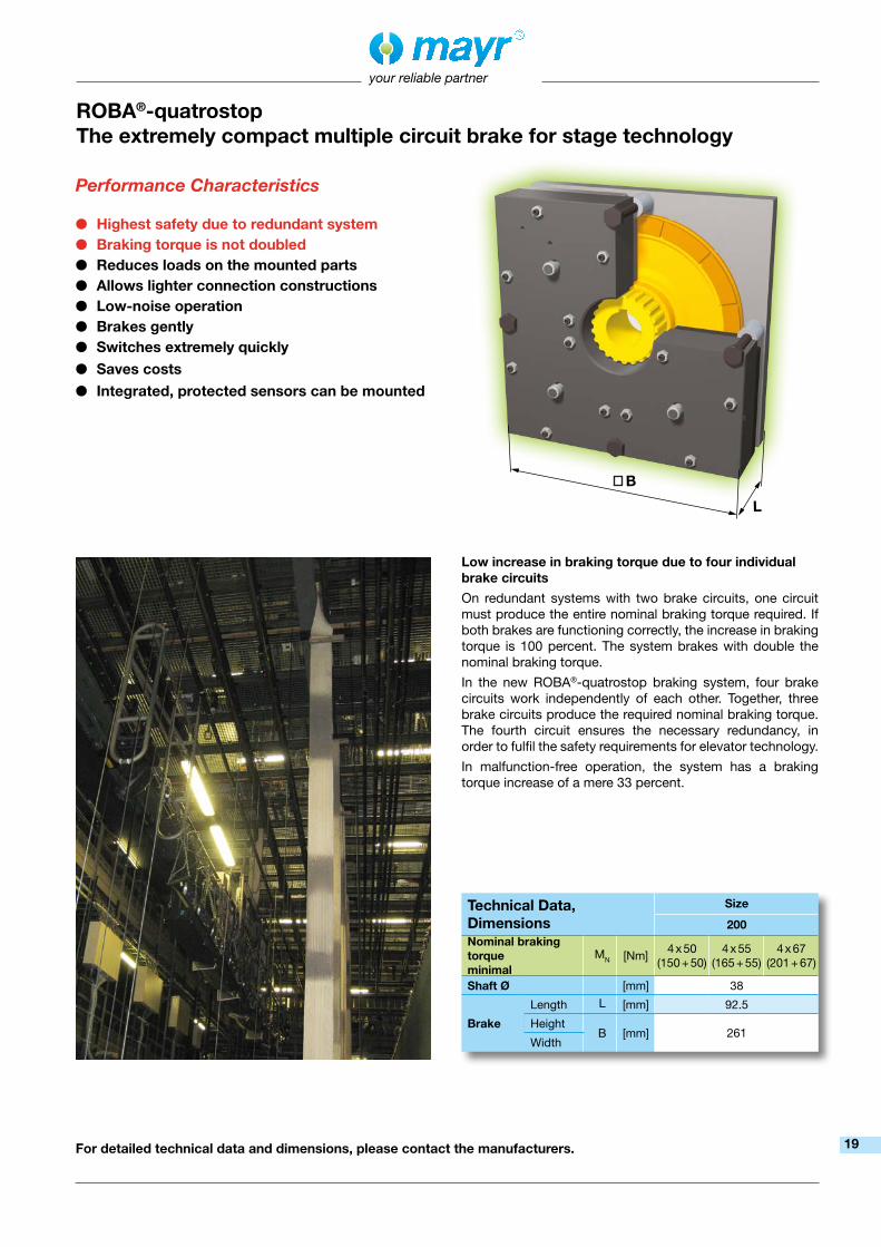
ROBA®-quatrostopThe extremely compact multiple circuit brake for stage technology
Low increase in braking torque due to four individual brake circuits
On redundant systems with two brake circuits, one circuit must produce the entire nominal braking torque required. If both brakes are functioning correctly, the increase in braking torque is 100 percent. The system brakes with double the nominal braking torque.
In the new ROBA®-quatrostop braking system, four brake circuits work independently of each other. Together, three brake circuits produce the required nominal braking torque. The fourth circuit ensures the necessary redundancy, in order to fulfil the safety requirements for elevator technology.
In malfunction-free operation, the system has a braking torque increase of a mere 33 percent.
For detailed technical data and dimensions, please contact the manufacturers.
Performance Characteristics
● Highest safety due to redundant system● Braking torque is not doubled● Reduces loads on the mounted parts● Allows lighter connection constructions● Low-noise operation● Brakes gently● Switches extremely quickly● Saves costs● Integrated, protected sensors can be mounted
Technical Data, Dimensions
Size
200Nominal braking torqueminimal
MN [Nm]4 x 50
(150 + 50)4 x 55
(165 + 55)4 x 67
(201 + 67)
Shaft Ø [mm] 38
Brake
Length L [mm] 92.5
Height B [mm] 261
Width
19

your reliable partner
For detailed technical data and dimensions, please see catalogue: ROBA-stop® K.800.V_ _._ _
ROBA-stop®-SThe waterproof, robust monoblock brake
Performance Characteristics
● Completely enclosed and sealed design in Protection IP67
● Robust, single-part monoblock housing● All components are corrosion-protected● High friction work is permitted● Can be used in extreme ambient conditions● Long-distance diagnosis via integration of
release monitoring and wear monitoring● Anti-condensation heating system to avoid
condensation formation inside the brake
Application fields
❑ Harbour/ship/seawater
❑ Outdoor applications
❑ Steel works
❑ Crane systems
❑ Heavy industries
❑ Recycling plants
❑ Environmental technology
Technical Data and DimensionsSize
8 9 10 11
Braking torque 1) M [Nm] 100 200 400 800
Shaft Ø [mm] 25 – 45 25 – 50 25 – 60 55 – 75
Brake
Outer Ø D [mm] 240 270 310 450
Length L [mm] 122 132.5 152 194.1
Height of terminal box H [mm] 155 167 185 217
1) Tolerance +40 % / -20 %
20

your reliable partner
no o
vere
xcita
tion
and
no
pow
er re
duct
ion
over
exci
tatio
n (s
hort
sep
arat
ion
time)
an
d /
or
pow
er re
duct
ion
(redu
ctio
n in
coi
l cap
acity
and
tem
pera
ture
)
Pro
tect
ion
ci
rcui
tS
afe
Bra
ke C
ont
rol
varia
ble
ou
tput
vo
ltage
fixed
ou
tput
vo
ltage
with
out
DC
-sid
e di
s-co
nnec
tion
inte
grat
ed
DC
-sid
e
disc
onne
ctio
n
Typ
e
024.
000.
6Ty
pe
02
5.00
0.6
Typ
e
017.
_00.
2Ty
pe
01
7.11
0.2
Typ
e
018.
000.
2 Ty
pe
01
8.10
0.2
Typ
e
028.
100.
2 Ty
pe
01
9._0
0.2
Typ
e
070.
000.
6Ty
pe
02
1.10
0.2
Hal
f-w
ave
R
ecti
fier
Pag
e 22
Bri
dg
e
Rec
tifi
er
Pag
e 22
RO
BA
®-s
wit
ch
Pag
e 23
RO
BA
®-s
wit
ch
Pag
e 24
RO
BA
®-s
wit
ch
24V
Pag
e 25
RO
BA
®-s
wit
ch
24V
Pag
e 26
RO
BA
®-
bra
ke-c
heck
er
Pag
e 27
RO
BA
®-
mul
tisw
itch
Pag
e 28
Sp
ark
Que
n-ch
ing
Uni
t
Pag
e 29
RO
BA
®-S
BC
plu
s
Pag
e 30
Ap
plic
atio
n
Sta
ndar
d
appl
icat
ion
Sta
ndar
d
appl
icat
ion,
pr
efer
red
for
nois
e-da
mpe
d br
akes
Allo
ws
shor
t se
para
tion
time
Allo
ws
shor
t se
para
tion
time
Allo
ws
shor
t sep
arat
ion
time
Allo
ws
shor
t se
para
tion
time
Red
uctio
ns in
sw
itch-
off
volta
ge
and
w
ear
on
cont
acts
Con
trol
s an
d m
onito
rs
up to
two
RO
BA
-sto
p®
safe
ty b
rake
s,
espe
cial
ly in
app
licat
ions
, w
hich
hav
e to
fulfi
ll re
quire
men
ts re
gard
ing
pers
on p
rote
ctio
n ac
cord
ing
to th
e st
anda
rds
for
func
tiona
l re
liabi
lity,
suc
h as
fo
r ex
ampl
e
ISO
138
49 a
nd IE
C 6
2061
+sh
ort
conn
ectio
n tim
e
+sh
ort c
onne
ctio
n tim
e+
cons
iste
ntly
co
ntro
lled
ou
tput
vol
tage
w
ith v
aria
ble
in
put v
olta
ge
+in
tegr
ated
re
leas
e an
d
drop
-out
reco
gni-
tion
for
perm
itted
br
akes
For
inpu
t vol
tage
24
VD
CFo
r in
put v
olta
ges
24
VD
C /
48
VD
C
max
. ou
tput
cur
rent
2.
5 A
max
. ou
tput
cur
rent
5
A
max
. ou
tput
cur
rent
10
A /
5 A
Com
pact
de
sign
Com
pact
de
sign
no w
ear
on
con
tact
sno
wea
r on
con
tact
s
Ele
ctri
cal A
cces
sori
es
For
det
aile
d in
form
atio
n o
n o
ur D
C v
olt
age
mo
dul
es, p
leas
e g
o t
o:
ww
w.m
ayr.c
om
Pate
nt
pend
ing
Func
tio
ns o
f th
e D
C V
olt
age
Mo
dul
es
Ele
ctri
cal A
cces
sori
es
21

AC
E
ØD
195
B
your reliable partner
Half-wave and bridge rectifiers Type 02_.000.6
ApplicationRectifiers are used to connect DC consumers to alternating voltage supplies, for example electromagnetic brakes and clutches (ROBA-stop®, ROBA-quick®, ROBATIC®), electromagnets, electrovalves, contactors, switch-on safe DC motors, etc.
FunctionThe AC input voltage (VAC) is rectified (VDC) in order to operate DC voltage units. Also, voltage peaks, which occur when switching off inductive loads and which may cause damage to insulation and contacts, are limited and the contact load reduced.
Electrical connection (Terminals)1 + 2 Input voltage3 + 4 Connection for an external switch for DC-side switching5 + 6 Coil7 – 10 Free nc terminals (only for Size 2)
Dimensions (mm)
Accessories: Mounting bracket set for 35 mm rail acc. EN 60715: Article No. 1803201.
Order Number
__ / 0 2 __ . 0 0 0 . 6
Size1 to 4
45
Half-wave rectifierBridge rectifier
Size A B C ØD E1 34 30 25 3.5 4.52 54 30 44 4.5 5.0
3/4 64 30 54 4.5 5.0
Technical Data Bridge rectifier Half-wave rectifier
Calculation output voltage VDC = VAC x 0.9 VDC = VAC x 0.45Type 1/025 2/025 1/024 2/024 3/024 4/024Max. input voltage ± 10% UAC [VAC] 230 230 400 400 500 600Max. output voltage UDC [VDC] 207 207 180 180 225 270
Output current≤ 50°C IRMS [A] 2.5 2.5 3.0 4.0 4.0 4.0at max. 85 °C IRMS [A] 1.7 1.7 1.8 2.4 2.4 2.4
Max. coil nominal capacity at
UAC = 115 VAC≤ 50 °C PN [W] 260 260 - - - -up to 85 °C PN [W] 177 177 - - - -
UAC = 230 VAC≤ 50 °C PN [W] 517 517 312 416 416 416up to 85 °C PN [W] 352 352 187 250 250 250
UAC = 400 VAC≤ 50 °C PN [W] - - 540 720 720 720up to 85 °C PN [W] - - 324 432 432 432
UAC = 500 VAC≤ 50 °C PN [W] - - - - 900 900up to 85 °C PN [W] - - - - 540 540
UAC = 600 VAC≤ 50 °C PN [W] - - - - - 1080up to 85 °C PN [W] - - - - - 648
Peak reverse voltage [V] 1600 1600 2000 1600 2000 2000Rated insulation voltage URMS [VRMS] 320 320 500 500 630 630Pollution degree (insulation coordination) 1 1 1 1 1 1Device Fuses To be included in the input voltage line.Recommended microfuse switching capacity HThe microfuse corresponds to the max. possible connection capacity. If fuses are used corresponding to the actual capacities, the permitted limit integral I2t must be observed on selection.
FF 3.15 A FF 3.15 A FF 4 A FF 5 A FF 5 A FF 5 A
Permitted limit integral l2t [A2s] 40 40 50 100 50 50Protection IP65 components, encapsulated / IP20 terminalsTerminals Cross-section 0.14 – 1.5 mm2 (AWG 26-14)Ambient temperature [°C] - 25 up to + 85Storage temperature [°C] - 40 up to + 85Conformity markings UL, CE UL, CE UL, CE UL, CE UL, CE CE
Installation conditionsThe installation position can be user-defined. Please ensure sufficient heat dissipation and air convection! Do not install near to sources of
intense heat!22

your reliable partner
ROBA®-switch Type 017._00.2
ApplicationROBA®-switch fast acting rectifiers are used to connect DC con-sumers to alternating voltage supplies, for example electromagnet-ic brakes and clutches (ROBA-stop®, ROBA®-quick, ROBATIC®) as well as electromagnets, electrovalves, etc.
Fast acting rectifier ROBA®-switch 017._00.2• Consumer operation with overexcitation or power reduction• Input voltage: 100 – 500 VAC• Maximum output current IRMS : 3 A at 250 VAC• UL-approved
FunctionThe ROBA®-switch is used for operation at an input voltage of between 100 and 500 VAC, depending on the size. It can switch internally from bridge rectification output voltage to half-wave rectification output voltage. The bridge rectification time can be modified from 0.05 to 2 seconds by exchanging the external resis-tor (Rext).
Electrical connection (Terminals)
1 + 2 Input voltage (fitted protective varistor)3 + 4 Connection for external contact for DC-side switch-off5 + 6 Output voltage (fitted protective varistor)7 + 8 Rext for bridge rectification time adjustment
Technical DataInput voltage see Table 1Output voltage see Table 1Protection IP65 components, IP20 terminals, IP10 Rext
Terminal nom. cross-section 1.5 mm2 (AWG 22-14)Ambient temperature - 25 °C up to + 70 °CStorage temperature - 40 °C up to + 70 °C
ROBA®-switch Sizes, Table 1
Dimensions (mm)
Type 017.000.2
Size
Type 017.000.2 Type 017.100.2
10 20 10 20
Input voltage ±10%
UAC [VAC] 100 – 250 200 – 500 100 – 250 200 – 500
Output voltage
Ubridge [VDC] 90 – 225 180 – 450 90 – 225 180 – 450
Uhalf-wave [VDC] 45 – 113 90 – 225 45 – 113 90 – 225
Output current
at ≤ 45 °C Ieff [A] 2.0 1.8 3.0 2.0
at max. 70 °C Ieff [A] 1.0 0.9 1.5 1.0
Conformity markings
Order Number
__ / 0 1 7 . __ 0 0 . 2
Size10 20
01
UL-approved up to 300 V up to 500 V
Type 017.100.2
up to 300 V
Accessories:
Mounting bracket set for 35 mm rail
acc. EN 60715:
Article No. 1802911
Accessories:
Mounting bracket set for 35 mm rail
acc. EN 60715:
Article No. 1802911
54
Ø4.5
4.5
54
64
5 9
30
17.5
48.5
1513
5.6
54
Ø4.5
4.5
54
64
5 9
30
17.5
73.6
1520
5.6
69
23

your reliable partner
ApplicationROBA®-switch fast acting rectifiers are used to connect DC consumers to alternating voltage supplies, for example electromagnetic brakes and clutches (ROBA-stop®, ROBA®-quick, ROBATIC®) as well as electromagnets, electrovalves, etc.
Fast acting rectifier ROBA®-switch 017.110.2• Integrated DC-side disconnection
(shorter connection time t1)• Consumer operation with overexcitation or power reduction• Input voltage: 100 – 500 VAC• Maximum output current IRMS : 1.5 A• UL-approved
FunctionThe ROBA®-switch is used for operation at an input voltage of between 100 and 500 VAC, depending on the size. It can switch internally from bridge rectification UO output voltage to half-wave rectification UH output voltage. The bridge rectification time can be modified from 0.05 to 2 seconds by exchanging the external resistor (Rext).
In addition, the ROBA®-switch features integrated DC-side disconnection. In contrast to the usual DC-side disconnection, no further protective measures or external components are required. The DC-side disconnection is activated as a standard measure (terminals 3 and 4 are not wired) and causes short switching times on the electromagnetic consumer.
The integrated DC-side disconnection is deactivated by fitting a bridge between the terminals 3 and 4, and the coil is de-energised via the freewheeling diode. This has the advantages of gentler braking actions and quieter switching noise. However, this substantially lengthens the switching times (approx. 6 – 10x).
Electrical connection (Terminals)
1 + 2 Input voltage (fitted protective varistor)3 + 4 Switching between DC and AC-side disconnection5 + 6 Output voltage (fitted protective varistor)7 + 8 Rext for bridge rectification time adjustment
Technical DataInput voltage see Table 1Output voltage see Table 1Protection IP65 components, IP20 terminals, IP10 Rext
Terminal nom. cross-section 1.5 mm2 (AWG 22-14)Ambient temperature -25 °C up to +70 °CStorage temperature -40 °C up to +70 °C
Dimensions (mm)
ROBA®-switch Sizes, Table 1
Size
10 20
Input voltage±10%
UI [VAC] 100 – 250 200 – 500
Output voltageUO [VDC] 90 – 225 180 – 450
UH [VDC] 45 – 113 90 – 225
Output current
at ≤ 45 °C IRMS [A] 1.5 1.5
at max. 70 °C IRMS [A] 0.75 0.75
Conformity markings
Order Number
__ / 0 1 7 . 1 1 0 . 2
Size10 20
The ROBA®-switch with integrated DC-side discon-nection is not suitable for being the only safety dis-connection in applications!
ROBA®-switch Type 017.110.2
Accessories:
Mounting bracket set for
35 mm rail acc. EN 60715:
Article No. 1802911
54
Ø4.5
4.5
54
64
5 9
30
17.5
73.6
1520
5.6
69
24

your reliable partner
ROBA®-switch 24V Type 018.000.2
ApplicationROBA®-switch 24V fast switching modules are used to operate DC consumers with overexcitation or power reduction, for example electromagnetic brakes and clutches (ROBA-stop®, ROBA®-quick, ROBATIC®), electromagnets, electrovalves, etc.
Fast switching module ROBA®-switch 24V 018.000.2
• Consumer operation with overexcitation or power reduction• Integrated DC-side disconnection (shorter connection time t1)• Input voltage: 24 VDC• Max. output current IRMS : 2.5 A
Dimensions (mm)
CAUTIONThe ROBA®-switch 24V with integrated DC-side disconnection is not suitable for being the only safety disconnection in applications!
FunctionThe ROBA®-switch 24V units are used for an input voltage of 24 VDC. They can switch internally, meaning that the output voltage switches to holding voltage from the input voltage (= overexcitation voltage) via pulse-width modulation using 20 kHz. The overexcitation time and holding voltage can be switched.
Electrical Connection (Terminals)1 Control input2 + 3 Input voltage, ground4 + 5 Input voltage +24V6 Output voltage +7 Output voltage -8 + 9 Selection of overexcitation time9 + 10 Selection ofholding voltage
Technical DataInput voltage UI 24 VDC (18 – 32 VDC) SELV/PELVOutput voltage UO Input voltage UI
Output voltage UH see Table 1Output current IRMS at ≤ 45 °C 2.5 AOutput current IRMS at max. 70 °C 1.25 AProtection IP65 components, IP20 terminalsTerminal nominal cross-section 1.5 mm² (AWG 22-14)Ambient temperature -25 °C up to +70 °CStorage temperature -40 °C up to +70 °C
Order Number
__ / 0 1 8 . 0 0 0 . 2
Size1
Article number
Overexcitation Time tO
[ms]
Holding voltage UH
[VDC]
Without with Without with
Bridge 8+9 Bridge 9+10
8237581 450 150 ½ x UI2/3 x UI
ROBA®-switch 24 V, Table 1
Example:
Order number 1 / 018.000.2 and article number 8237581
Accessories:
Mounting bracket set for 35
mm rail acc. EN 60715:
Article No. 1802911
54
Ø4.5
4.5
54
64
5 9
30
17.5
48.6
15
5.6
25

1 2 3 4 5 6 7 8 9 10
ON
1 2 3 4
ON
1 2 3 4
your reliable partner
ApplicationROBA®-switch 24V fast switching modules are used to oper-ate DC consumers with overexcitation or power reduction, for example electromagnetic brakes and clutches (ROBA-stop®, ROBA®-quick, ROBATIC®), electromagnets, electrovalves, etc.
Fast switching module ROBA®-switch 24V 018.100.2• Consumer operation with overexcitation or power reduction• Integrated DC-side disconnection (shorter connection time t1)• Input voltage: 24 VDC• Max. output current I: 5 A 5 A• UL-approved
Dimensions (mm)
Order Number
__ / 0 1 8 . 1 0 0 . 2
Size1
ROBA®-switch 24V Type 018.100.2
FunctionThe ROBA®-switch 24V units are used for an input voltage of 24 VDC. They can switch internally, meaning that the output voltage switches to holding voltage from the input voltage (=overexcitation voltage) via pulse-width modulation using 20 kHz. The overexcitation time can be adjusted via a DIP switch to 150 ms, 450 ms, 1 s, 1.5 s and 2.15 s. The holding voltage can be adjusted via a further DIP switch to ¼, 1/3, ½ and 2/3 of the input voltage (equals 6 V, 8 V, 12 V and 16 V at an input voltage of 24 V).
In addition, the ROBA®-switch 24V features integrated DC-side disconnection. In contrast to the usual DC-side disconnection, no further protective measures or external components are required. The DC-side disconnection is activated in standard mode and causes short switching times on the electromagnetic consumer. This can, however, be deactivated by installing a bridge between terminals 7 and 8 in order to produce soft brakings and quieter switching noises. However, this substantially lengthens the switching times (approx. 6 – 10x).
Electrical Connection (Terminals)2 + 3 Input voltage, ground4 Control input5 – 7 Input voltage + 24 VDC8 + 9 Output voltage +10 Output voltage -
Technical DataInput voltage UI 24 VDC + 20 % / - 10 % SELV/PELVOutput voltage UO Input voltage UI
Output voltage UH ¼, 1/3, ½, 2/3 x UI ± 20 % can be selected via a DIP switchOutput current IRMS at ≤ 45 °C 5.0 AOutput current IRMS at max. 70 °C 2.5 AProtection IP00Terminal nominal cross-section 1.5 mm² (AWG 22-14)Ambient temperature -25 °C up to +70 °CStorage temperature -40 °C up to +70 °C
CAUTIONThe ROBA®-switch 24V with integrated DC-side disconnection is not suitable for being the only safety disconnection in applications!
Accessories:
Mounting bracket set for 35 mm
rail acc. EN 60715:
Article No. 1802911
54
Ø4.5
4.5
54
69
5 9
30
17.5
73.6
15
5.6
20
64
26

ON
1 2 3 4 5 6 7 8
your reliable partner
ApplicationROBA®-brake-checker monitoring modules are used to operate DC consumers. Motion monitoring of the armature disk for released ROBA-stop® safety brakes is possible.
Monitoring module ROBA®-brake-checker 028.100.2• Consumer operation with overexcitation and/or power reduction• Controlled holding voltage (on reduction)• Simple adjustment of holding voltage and overexcitation time via
a DIP switch• Fast or slow switch off• Armature disk motion recognition
(release and drop-out recognition)• Preventative function monitoring (Wear recognition and error
recognition, functional reserve)• Wide input voltage range• Maximum output current I = 10 A / 5 A• Maximum overexcitation current IO = 20 A / 10 A• Automatic reduction of the holding voltage UH
• Electrical isolation of performance terminal and control terminal Dimensions (mm)
Sizes2 4
24 VDC 48 VDCInput voltage, power terminal
SELV/PELV UI [VDC] 18 – 30 42 – 54
Input voltage, signal terminal
UI [VDC]24
(19 – 28)
Output voltage± 5 % UO [VDC] Input voltage UI
± 5 % UH [VDC]6 8 12 1612 16 24 32
Output currentat ≤ 45 °C IRMS [ADC] 10.0 5.0
at max. 70 °C
IRMS [ADC] 5.0 2.5
Conformity markings
Order Number
__ / 0 2 8 . 1 0 0 . 2
Sizes24
CAUTIONThe ROBA®-brake-checker with integrated DC-si-de disconnection is not suitable for being the only safety disconnection in applications!
FunctionThe ROBA®-brake-checker monitoring module is intended for use with an input voltage of 24 or 48 VDC. The module monitors the movement of the armature disk and emits the determined switching condition via control terminal 3 (signal output).Critical conditions (line breakages, wear) can be recognised and the respective signal can be emitted via control terminal 7 (error output).
After a brake-specific overexcitation time period, the integrated automatic voltage mechanism mode adjusts to the pre-set reduction voltage. The automatic voltage mechanism mode can be switched off using a DIP switch.
In case of switched-off automatic voltage mechanism mode, the overexcitation time can be adjusted manually to 150 ms, 450 ms, 1 s, 1.5 s, and 2 s using the DIP switch.
Electrical Connection (Terminals)Power Terminal1 Supply voltage +24 VDC / +48 VDC2 Output voltage +3 Output voltage -4 Supply voltage 0 VDC
Signal Terminal1 Supply voltage 0 VDC2 Switch-off fast/slow (input)3 Signal output (release monitoring)4 24 V (auxiliary voltage for bridging)5 Supply voltage +24 VDC6 Start (input)7 Error output max. 300 mA
Technical DataInput voltage see Table 1Output voltage see Table 1Protection IP65 components, IP20 terminals, IP20 DIP switchTerminal nominal cross-section Power terminals 4 mm2, (AWG 20-12) Signal terminals 1.5 mm2, (AWG 30-14)Ambient temperature -25 °C up to +70 °CStorage temperature -40 °C up to +105 °C
ROBA®-brake-checker Sizes, Table 1
Accessories: Mounting bracket set for 35 mm rail acc. EN 60715:Article No. 1802911
54
Ø4.5
4.5
54
69
9
30
17.5
73.6
15
5.6
20
64
5
27
ON
1 2 3 4
your reliable partner
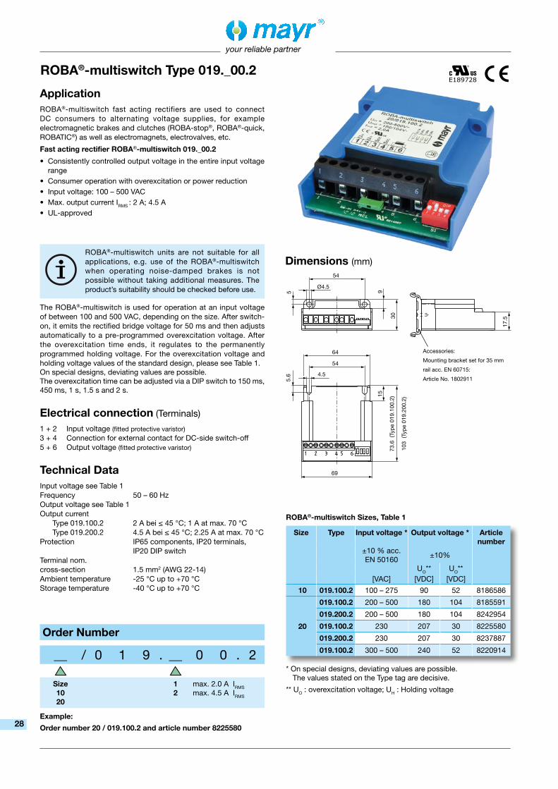
ROBA®-multiswitch Type 019._00.2
ApplicationROBA®-multiswitch fast acting rectifiers are used to connect DC consumers to alternating voltage supplies, for example electromagnetic brakes and clutches (ROBA-stop®, ROBA®-quick, ROBATIC®) as well as electromagnets, electrovalves, etc.
Fast acting rectifier ROBA®-multiswitch 019._00.2
• Consistently controlled output voltage in the entire input voltage range
• Consumer operation with overexcitation or power reduction• Input voltage: 100 – 500 VAC• Max. output current IRMS : 2 A; 4.5 A• UL-approved
FunctionThe ROBA®-multiswitch is used for operation at an input voltage of between 100 and 500 VAC, depending on the size. After switch-on, it emits the rectified bridge voltage for 50 ms and then adjusts automatically to a pre-programmed overexcitation voltage. After the overexcitation time ends, it regulates to the permanently programmed holding voltage. For the overexcitation voltage and holding voltage values of the standard design, please see Table 1.On special designs, deviating values are possible.The overexcitation time can be adjusted via a DIP switch to 150 ms, 450 ms, 1 s, 1.5 s and 2 s.
Electrical connection (Terminals)
1 + 2 Input voltage (fitted protective varistor)3 + 4 Connection for external contact for DC-side switch-off5 + 6 Output voltage (fitted protective varistor)
Technical DataInput voltage see Table 1Frequency 50 – 60 HzOutput voltage see Table 1Output current Type 019.100.2 2 A bei ≤ 45 °C; 1 A at max. 70 °C Type 019.200.2 4.5 A bei ≤ 45 °C; 2.25 A at max. 70 °CProtection IP65 components, IP20 terminals, IP20 DIP switchTerminal nom. cross-section 1.5 mm2 (AWG 22-14)Ambient temperature -25 °C up to +70 °CStorage temperature -40 °C up to +70 °C
ROBA®-multiswitch units are not suitable for all applications, e.g. use of the ROBA®-multiswitch when operating noise-damped brakes is not possible without taking additional measures. The product’s suitability should be checked before use.
Dimensions (mm)
ROBA®-multiswitch Sizes, Table 1
Order Number
__ / 0 1 9 . __ 0 0 . 2
Size1020
12
max. 2.0 A IRMS
max. 4.5 A IRMS
* On special designs, deviating values are possible. The values stated on the Type tag are decisive.
** UO : overexcitation voltage; UH : Holding voltage
Size Type Input voltage * Output voltage * Article number
±10 % acc. EN 50160
±10%
UO** UO**[VAC] [VDC] [VDC]
10 019.100.2 100 – 275 90 52 8186586
20
019.100.2 200 – 500 180 104 8185591
019.200.2 200 – 500 180 104 8242954
019.100.2 230 207 30 8225580
019.200.2 230 207 30 8237887
019.100.2 300 – 500 240 52 8220914
Example:
Order number 20 / 019.100.2 and article number 8225580
73.6
(Ty
pe 0
19.1
00.2
)
103
(Typ
e 01
9.20
0.2)
Accessories:
Mounting bracket set for 35 mm
rail acc. EN 60715:
Article No. 1802911
54
Ø4.5
4.5
54
69
9
30
17.5
15
5.6
64
5
28

your reliable partner
ApplicationReduces spark production on the switching contacts occurring during DC-side switch-off of inductive loads.
• Voltage limitation according to VDE 0580 2000-07, Item 4.6.• Reduction of EMC-disturbance by voltage rise limitation,
suppression of switching sparks.• Reduction of brake engagement times by a factor of 2 – 4
compared to freewheeling diodes.
FunctionThe spark quenching unit will absorb voltage peaks resulting from inductive load switching, which can cause damage to insulation and contacts. It limits these to 70 V and reduces the contact load. Switching products with a contact opening distance of > 3 mm are suitable for this purpose.
Electrical Connection (Terminals)
1 (+) Input voltage2 (–) Input voltage3 (–) Coil4 (+) Coil5 Free nc terminal6 Free nc terminal
Technical DataInput voltage max. 300 VDC, max. 615 Vpeak
(rectified voltage 400 VAC, 50/60 Hz)
Switch-off energy max. 9 J / 2 msPower dissipation max. 0.1 Watt Rated voltage nc terminals 250 VProtection IP65 components, IP20 terminalsAmbient temperature -25 °C up to +85 °CStorage temperature -40 °C up to +85 °CMax. conductor cross-section 2.5 mm2, (AWG 26-12)Max. terminal tightening torque 0.5 Nm
AccessoriesMounting bracket set for 35 mm rail acc. EN 60715:Article No. 1803201
Dimensions (mm)
Order Number
__ / 0 7 0 . 0 0 0 . 6
Size1
Spark quenching unit Type 070.000.6
34
25
4.5
30
Ø3.
5
19
5
29

your reliable partner
ROBA®-SBCplus The safe brake control - for use up to PLe and SIL CL3
ApplicationThe safe brake control ROBA®-SBCplus is used to control and monitor two ROBA-stop® safety brakes, especially in applications, which have to fulfill requirements regarding person protection according to the standards for functional reliability, such as for example ISO 13849 and IEC 62061.
Maximum switching reliability The brake control must safely interrupt the current in the magnetic coil on switching off the brake. The ROBA®-SBCplus module works with wear-free electronic semiconductors and thus achieves almost unlimited switching frequencies and switching reliability.
Safe inner configurationAmongst other things, the internal diagnostics inspections for short circuits, earth short-circuits and line breaks as well as safe overexcitation for releasing the brake and switching to reduced holding voltage when the brake is opened are the components required for “fail-safe” inner configuration.
Numerous safety functionsNumerous safety functions permit comprehensive error diagnostics. The brake voltage is monitored. An excessively high voltage could dangerously extend the drop-out time on switch-off, if, for example, this were to cause a vertical axis to drop to an unpermittedly low level. The monitoring of the switching times, which influence the braking distance, is therefore another component of error diagnostics.
Safe switching condition monitoringThe signal evaluation of the release monitoring with plausibility check permits a switching condition monitor-ing of the brake. The plausibility is controlled as follows: If voltage is applied, the brake must be opened after a defined time and vice versa. The switching condition monitoring can be used to reliably prevent the drive starting up against a closed brake. In this way, creeping errors, such as gradually increasing wear, which affects the switching times, can be detected.
Characteristics:
● Safe electronic switching of two brakes ● Input voltage power circuit 24 - 48 VDC ● Connection for up to 2 brakes up to 4.5 A / 24
VDC or 2.25 A / 48 VDC (108 W) ● Output voltage (holding voltage) can be selected
6,8,12,24,48 VDC➞ Power reduction, temperature reduction,
electricity costs reduction ● Overexcitation time configurable ● Feedback inputs release monitoring for
proximity switch or microswitch ● Monitoring for plausibility of the feedback
➞ Error diagnostics of the brake ● Status and error outputs for feedback
to the control ● No mechanic contacts for controlling
and monitoring➞ High reliability, no wear, independent
of cycle frequency and cycle rate ● Fast (“DC-side”) or slow (“AC-side”)
switch off possible ● Galvanic separation between the
control part and the power part➞ Prevention of EMC issues
● Four integrated functions:Contactor, 24 VDC fast-acting rectifier, safety relay, spark quenching
● Safe holding voltage and overexcitation time ● Safety functions are programmed into the RO-
BA®-SBCplus and only have to be parameterised➞ Plausibility check integrated and must not be programmed and validated
● Applicable up to PLe and SIL CL3, Type examination TÜV Sud (German Technical Inspectorate)
Patent
pending
30
your reliable partner
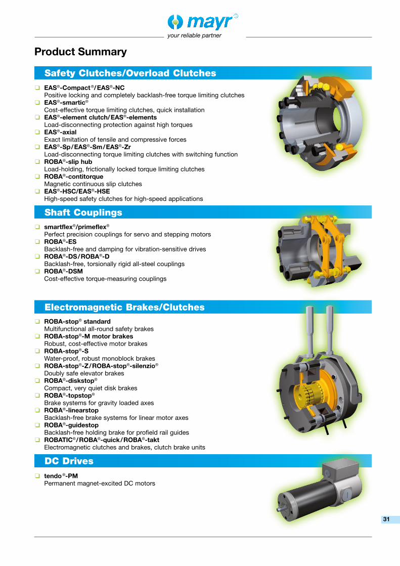
Product Summary
❑ ROBA-stop® standard Multifunctional all-round safety brakes
❑ ROBA-stop®-M motor brakes Robust, cost-effective motor brakes
❑ ROBA-stop®-S Water-proof, robust monoblock brakes
❑ ROBA-stop®-Z/ROBA-stop®-silenzio® Doubly safe elevator brakes
❑ ROBA®-diskstop® Compact, very quiet disk brakes
❑ ROBA®-topstop® Brake systems for gravity loaded axes
❑ ROBA®-linearstop Backlash-free brake systems for linear motor axes
❑ ROBA®-guidestop Backlash-free holding brake for profield rail guides
❑ ROBATIC®/ROBA®-quick/ROBA®-takt Electromagnetic clutches and brakes, clutch brake units
❑ smartflex®/primeflex® Perfect precision couplings for servo and stepping motors
❑ ROBA®-ES Backlash-free and damping for vibration-sensitive drives
❑ ROBA®-DS/ROBA®-D Backlash-free, torsionally rigid all-steel couplings
❑ ROBA®-DSM Cost-effective torque-measuring couplings
❑ EAS®-Compact®/EAS®-NC Positive locking and completely backlash-free torque limiting clutches
❑ EAS®-smartic® Cost-effective torque limiting clutches, quick installation
❑ EAS®-element clutch/EAS®-elements Load-disconnecting protection against high torques
❑ EAS®-axial Exact limitation of tensile and compressive forces
❑ EAS®-Sp/EAS®-Sm/EAS®-Zr Load-disconnecting torque limiting clutches with switching function
❑ ROBA®-slip hub Load-holding, frictionally locked torque limiting clutches
❑ ROBA®-contitorque Magnetic continuous slip clutches
❑ EAS®-HSC/EAS®-HSE High-speed safety clutches for high-speed applications
❑ tendo®-PM Permanent magnet-excited DC motors
Safety Clutches/Overload Clutches
Shaft Couplings
Electromagnetic Brakes/Clutches
DC Drives
31

Representatives
More representatives:
Austria, Belgium, Brazil, Canada, Denmark, Finland, Greece, Hongkong, Hungary, Indonesia, Israel, Luxembourg, Malaysia, New Zealand, Norway, Philippines, Romania, Russia, Slovakia, Slovenia, South Africa, Spain, Sweden, Thailand, TurkeyYou can find the complete address for the representative responsible for your area under www.mayr.com in the internet.
Headquarters
Chr. Mayr GmbH + Co. KGEichenstraße 1, D-87665 MauerstettenTel.: +49 83 41/8 04-0, Fax: +49 83 41/80 44 21www.mayr.com, E-Mail: [email protected]
Branch office
Service Germany
Baden-WürttembergEsslinger Straße 770771 Leinfelden-EchterdingenTel.: 07 11/45 96 01 0Fax: 07 11/45 96 01 10
BavariaEichenstraße 187665 MauerstettenTel.: 0 83 41/80 41 04Fax: 0 83 41/80 44 23
ChemnitzBornaer Straße 20509114 ChemnitzTel.: 03 71/4 74 18 96Fax: 03 71/4 74 18 95
FrankenUnterer Markt 991217 HersbruckTel.: 0 91 51/81 48 64Fax: 0 91 51/81 62 45
KamenLunener Straße 21159174 KamenTel.: 0 23 07/23 63 85Fax: 0 23 07/24 26 74
NorthSchiefer Brink 832699 ExtertalTel.: 0 57 54/9 20 77Fax: 0 57 54/9 20 78
Rhine-MainHans-Böckler-Straße 664823 Groß-Umstadt Tel.: 0 60 78/7 82 53 37Fax: 0 60 78/9 30 08 00
ChinaMayr ZhangjiagangPower Transmission Co., Ltd. Fuxin Road No.7, Yangshe Town215637 ZhangjiagangTel.: 05 12/58 91-75 67Fax: 05 12/58 91-75 [email protected]
Great BritainMayr Transmissions Ltd.Valley Road, Business ParkKeighley, BD21 4LZWest YorkshireTel.: 0 15 35/66 39 00Fax: 0 15 35/66 32 [email protected]
FranceMayr France S.A.S.Z.A.L. du MinopoleRue Nungesser et Coli62160 Bully-Les-MinesTel.: 03.21.72.91.91Fax: [email protected]
ItalyMayr Italia S.r.l.Viale Veneto, 335020 Saonara (PD)Tel.: 0498/79 10 20Fax: 0498/79 10 [email protected]
SingaporeMayr Transmission (S) PTE Ltd.No. 8 Boon Lay Way Unit 03-06, TradeHub 21Singapore 609964 Tel.: 00 65/65 60 12 30Fax: 00 65/65 60 10 [email protected]
SwitzerlandMayr Kupplungen AGTobeläckerstraße 118212 Neuhausen am RheinfallTel.: 0 52/6 74 08 70Fax: 0 52/6 74 08 [email protected]
USAMayr Corporation10 Industrial AvenueMahwahNJ 07430Tel.: 2 01/4 45-72 10Fax: 2 01/4 45-80 [email protected]
AustraliaRegal Beloit Australia Pty Ltd.19 Corporate Ave03178 Rowville, VictoriaAustralienTel.: 0 3/92 37 40 00Fax: 0 3/92 37 40 [email protected]
IndiaNational EngineeringCompany (NENCO)J-225, M.I.D.C. Bhosari Pune 411026Tel.: 0 20/27 13 00 29Fax: 0 20/27 13 02 [email protected]
JapanMATSUI Corporation2-4-7 AzabudaiMinato-kuTokyo 106-8641Tel.: 03/35 86-41 41Fax: 03/32 24 24 [email protected]
NetherlandsGroneman BV Amarilstraat 117554 TV Hengelo OVTel.: 074/2 55 11 40Fax: 074/2 55 11 [email protected]
PolandWamex Sp. z o.o. ul. Pozaryskiego, 2804-703 WarszawaTel.: 0 22/6 15 90 80Fax: 0 22/8 15 61 [email protected]
South KoreaMayr Korea Co. Ltd.15, Yeondeok-ro 9beon-gilSeongsan-gu51571 Changwon-siGyeongsangnam-do. KoreaTel.: 0 55/2 62-40 24Fax: 0 55/2 62-40 [email protected]
TaiwanGerman Tech Auto Co., Ltd.No. 28, Fenggong Zhong Road, Shengang Dist.,Taichung City 429, Taiwan R.O.C.Tel.: 04/25 15 05 66Fax: 04/25 15 24 [email protected]
Czech RepublicBMC - TECH s.r.o.Hviezdoslavova 29 b62700 BrnoTel.: 05/45 22 60 47Fax: 05/45 22 60 [email protected]
HagenIm Langenstuck 658093 HagenTel.: 0 23 31/78 03 0Fax: 0 23 31/78 03 25
your reliable partner
16/0
1/20
17 G
F/S
C


