Download - Z, ITP Workshop

Office ofAeronautics andSpaceTechnology
NASP TECHNOLOGY TRANSFER
Presentation to
ITP Workshop
Charles MorrisAssistant DirectorMarch 18, 1992
O'J.I '
Z,
NATIONAL AERO-SPACE PLANE (NASP)
f
5_x m_
F- f
GOAL: To develop and then demonstrate the technologies forsingle-stage-to-orbit flight and hypersonic cruise withairbreathing primary propulsion and horizontal takeoffand landing
VALUE: • technology for flexible, efficient access to space
• technology for hypersonic cruise
• advancement of U.S. aerospace-technology base
"I"2-1
https://ntrs.nasa.gov/search.jsp?R=19930021524 2020-03-17T04:31:16+00:00Zbrought to you by COREView metadata, citation and similar papers at core.ac.uk
provided by NASA Technical Reports Server
INTERNATIONAL AEROSPACE-PLANE TECHNOLOGY
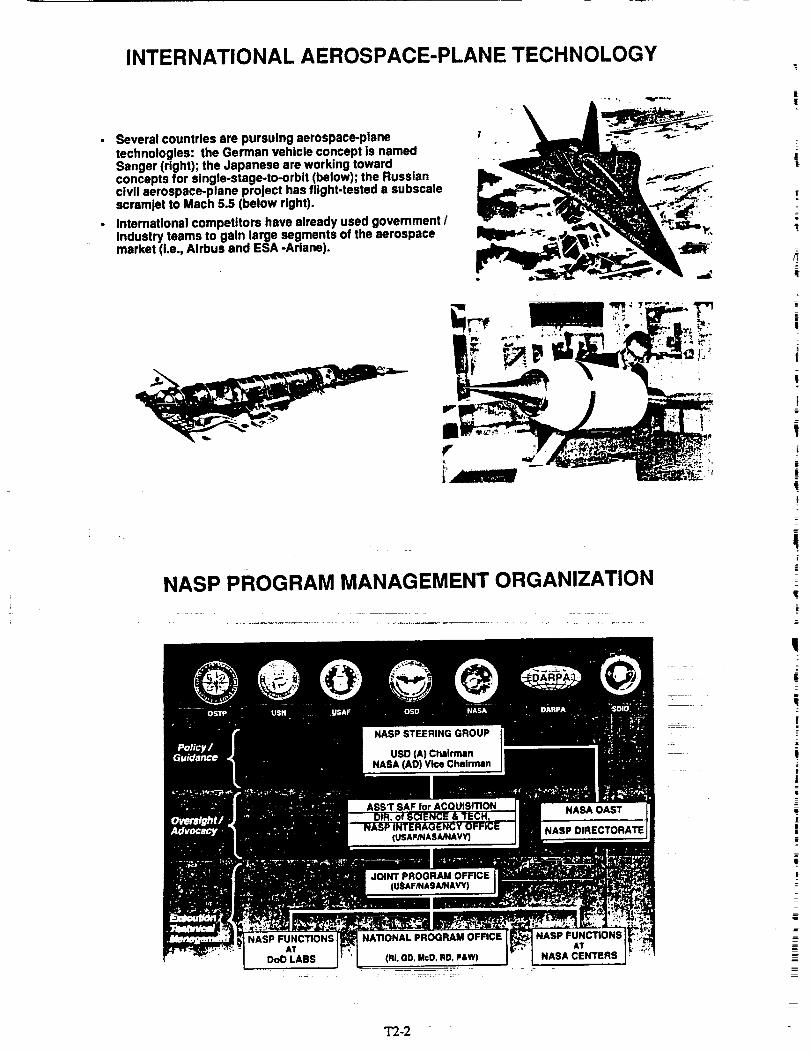
• Several countries are pursuing aerospace-planetechnologies: the German vehicle concept is namedSanger (right); the Japanese are working towardconcepts for single-stage-to-orbit (below); the Russiancivil aerospace-plane project has flight-tested a subscalescramJet to Mach 5.5 (below right).
• International competitors have already used government /industry teams to gain large segments of the aerospacemarket (i.e., Airbus and ESA -Ariane).
ir
iii,¢
NASP PROGRAM MANAGEMENT ORGANIZATION
NASP FUNCTIONS NATIONAL PROGRAM OFFICE
AT AT
DoDLASS (RIoOO,MoO,RD,P&W) NASACENTERS
_ - _-:: :r _
T2-2
q
t
i
w7_
!
i
!
|
i
=
i
|
!
|
|-a
m
|
I
|
z
IB
=
NASP NATIONAL TEAM
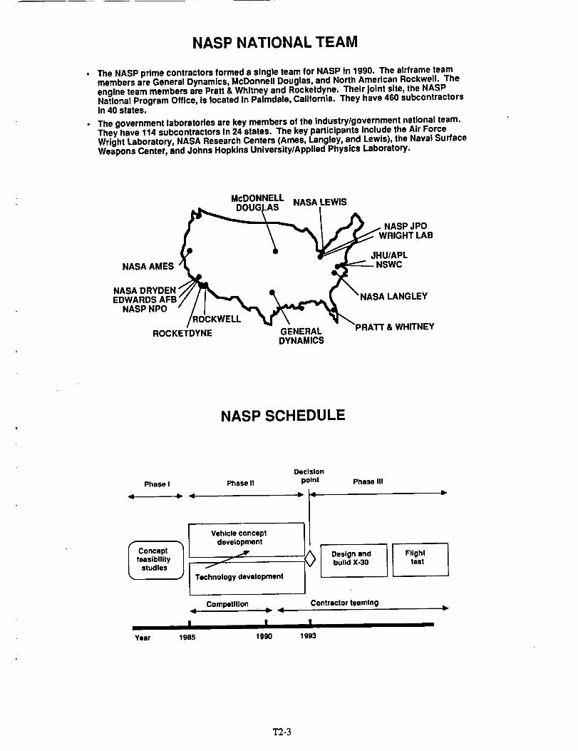
• The NASP prime contractors formed a single team for NASP in 1990. The airframe teammembers are General Dynamics, McDonnell Douglas, and North American Rockwell. Theengine team members are Pratt & Whitney and Rocketdyne. Their Joint site, the NASPNational Program Office, is located in Palmdale, California. They have 460 subcontractorsin 40 states.
• The government laboratories are key members of the industry/government national team.They have 114 subcontractors in 24 states. The key participants Include the Air ForceWright Laboratory, NASA Research Centers (Ames, Langley, and Lewis), the Naval SurfaceWeapons Center, and Johns Hopkins University/Applied Physics Laboratory.
McDONNELL NASA LEWIS/DOU(
__-_-----'_L / ._ .._ NASP JPO
X - 4F_ ( _ JHU/APL
NASA AMES "_ _NSWC
NASA DRYDEN "//_ • /"
• - -PRATt &ROCKETDYNE GENERAL WHITNEYDYNAMICS
NASP SCHEDULE
Decision
Phase I Phase II point Phase III
Vehicle concept
Concept ._, ,,,,,Vfeasibility
studies l /Technology development
Competition
I IYear 1985 1990
Design andbuild X-30
II Flighttest
Contractor teaming
I1993
T2-3

NASP VEHICLE CONCEPT(X-30)
• Payload: instrumentation <:_--_ _____r___J/-_'
• Lifting-body shape with delta wings
• Flattened nose: lower drag and smoother Inflow to engine
• Propulsion: low.speed system I ramjet / scramjet / rocket
• Fuel: slush hydrogen
i Cryogenic fuel tank: graphite epoxy ,._..__'--X _--_/-- .......Fuselage shell: fiber-reinforced titanium ................... _,=,_'----_ _ x_J__'_'_ _
Thermal protection: carbon-carbon panels, active cooling, ,-., ,,- --__
and passive cooling (heat pipe) _=..,,__
T_ WlKS
KEY AERO-SPACE PLANE TECHNOLOGIES
IADVANCEDAVIONICS I
CRYO TANK/STRUCTURESLUSH HYDROGEN
ADVANCEDMATERIALS
I CONTROL ACTIVELYSYSTEM
INTEGRATION COOLEDSTRUCTURE
|
!=
T2-4

NASP PROPULSION TECHNOLOGY
• The NASP propulsion systems must perform ........efficiently between Mach 0 and 25.
• 1/4 to 1/6-scale model scramjets (above left) havebeen tested in conditions simulating flight as fastas Mach 8.
• The NASP data base Includes ground-test resultson components, such as fuel injectors (aboveright), for flight conditions up to Mach 17.
NASP PROPULSION TECHNOLOGY - NOZZLES
• The rear undersurface of the X-30 actsas a nozzle - the pressure of theexhaust provides thrust.
• Wind-tunnel tests (right) explored X-30performance and allowed validation ofcomputer codes.
• Flight tests with an F-18 aircraft (below)complemented wind-tunnel data onexternal burning - a way to reducenozzle drag at transonic speeds.
1"2-5

NASP STRUCTURES AND MATERIALS
• Movable panels in extremely hot regionsof the engines require edge seals (right).Tests with red-hot fixtures verifiedsealing properties of "rope" and ceremicwafer seals (below right).
• Structural tests of a simulated wingsegment (below) revealed a need toImprove computer modeling of sometitanium metal-matrix structures.
[i"
SRIm
' NASP STRUCTURES AND MATERIALS
• On February 7, 1992, It was filled with liquidhydrogen (at -423 ° F). The assembly then -successfully endured bending and heating(1300 ° F) loads on the shell that simulatedMach 16, NASP conditions .............
A 900-gallon graphite-ep0xy fue| tankInstalled in a simulated fuselage shell oftitanium metal-matrix composite was tested atWyleLabs in Norco, Californ[a.i_ :_:_i; i_ .... _
"1"2-6
!

i NASP AEROTHERMODYNAMICS
• Much initial aerothermal testing wasdone with the Test-TechniquesDemonstrator ('l'rD) model, shown here.
• The pictures show models forsupersonic tests (above) and subsonic,"free-flight" tests with thrusting enginesimulators (above right).
• A digitized, "false-color" Image ofserothermal heating on the "I'I'D nose isshown for Mach 10 flow (right).
NASP AEROPROPULSION INTEGRATION
• The propulsion system and the aerodynamic systems Interact in different ways In differentparts of the flight profile.
• Results for a powered "l-rD-type model In wind-tunnel tests were verified by computercalculations. They show strong interactions between exterior aerodynamics andpropulsion on takeoff.
"1"2-7

NASP COMPUTATIONAL FLUID DYNAMICS (CFD)
Powerful supercomputers allow theexploration of propulsion phenomenasuch as an engine unstart, somethinglike a backfire, at Mach 10 (right).
St_c:l soluti_
Low
CFD calculations for the 1"I'D at Machl0predict nozzle perf0_ance and exhausteffects on tall control surfaces (left).
NASP SYSTEMS RESEARCH AND DEVELOPMENT
• Slush hydrogen, a mixture of frozen and liquidhydrogen, has greater density and heat-sinkcapability than liquid hydrogen. Scaled-upsystems have demonstrated production ofover 50,000 gallons of slush. A 5-foot diametertank (right) provided crucial data on slushhandling and transfer.
• NASP instrumentation must give goodinlormation at extreme conditions. The test,pictured below, shows strain-gages measuringloads at 1775 degrees Fahrenheit.
_l_i; ii ,

NATIONAL AERO-SPACE PLANE
• NASP is developing the technologies to satisfy important U.S. civil andmilitary needs
• NASP Is making significant technical progress
• NASP remains a technically challenging program
• NASP needs full I=Y93 funding to ensure continued progress
"C" ' '' "
!
Only after flight validation can the technologies be applied to thenext generation of aerospace vehicles with confidence and safety
NASP TECHNOLOGY TRANSFER MECHANISMS
• NASP JOINT PROGRAM OFFICE:
- JPO CONTRACTOR SUPPORT (SAIC)
- USAF RESERVISTS TEAM
- SDIO TECHNOLOGY APPLICATIONS INFORMATION SYSTEM
• NASA - STANDARD T.U. CONTACTS - "TECH BRIEFS," ETS.
• JOINT ACTIVITIES: FOCUSED WORKSHOPS
(EX: MATERIALS AND INSTRUMENTATION TECHNOLOGY
WORKSHOP AT LANGLEY ON MARCH 24 AND 25, 1992)
• NASP CONTRACTORS AND SUBCONTRACTORS
1"2-9

NASP TECHNOLOGY TRANSFER CONTACTS
II I
NASP JOINT PROGRAM OFFICE_
- APPLICATIONS DIRECTORATE (COL. MATTHEWS,
BILL POWEL L, ..... ) _ _ _
- SPECIAL ASSISTANT FOR TECH. TRANS. (DICK CULPEPPER)
NASA, CODE C-TEcHNOLoGY UTILIZATION OFFICE
(RAY GILBERT) _- _::: _±
- NASA, CODE RN - NASP DIRECTORATE (CHARLES MORRIS)
NASP TECHNOLOGYTRANSFERCHALLENGESI
• IDENTIFICATION OF TECHNOLOGY APPLICATIONS
(RE.: "CONNECTIONS" BY BURKE)
• PROGRAM. PROTECTION- SOME OF NASP PROGRAM IS
CLASSIFIED AN D SOME IS PROTECTED BY ITAR
• CONTRACTOR RETICENCE TO IDENTIFY APPLICATION
BEFORE "CONTROL" OF MARKET
• TRANSFER TO U.S. VERSUS OTHERS: PATENTS, SDIO
SYSTEM; ETC. . _: _ ,_ _ :
• PRESSURE ON TECHNICAL COMMUNITY MEMBERS TO- : = _ .... r = -= :: _ c:z zz= : r= _ _ ::
"PUBLISH OR PERISH" .-> UNCONTROLLED DISSEMINATION
• FOREIGN COUNTRIES HAVE ORGANIZATIONS TO ENHANCE. . , = = : _-_= ::::TECHNOLOGY TRANSFER FROM U.S.
T2-]0
k
|i
!=
!
!
£
|
_=
_==B
|I
!|=
=v

_,_ .,___..._,_,_ UNCLASSIFIED
1991 U.S. Balance of Trade Estimates*
36.2 •
6.8
Aerospace I 13.5 Billion
AgdCulturs I = 12.2
Computers { _ 12.0
2.0 _ Paper
2.9 i Non-Electrical Machinery
3.8 m Instruments
' _ Shoes and Leather
1%'Sets, Radios, Phonographs
l Apparel
Motor Vehicles
• Potential Impact of NASP Technology is Significant (m)
* Source: Univ. of Md INFORUM Model
UNCLASSIFIED
UNCLASSIFIED
|"_ 81_ -----
Computational Fluid Dynamics (CFD)
Technology Description
• High Speed Computing Tool
Predicts Aerodynamics of Aircraft, Missiles, Aut(_
- Models Internal Flows of Aircraft, Auto Engines
NASP Impact on CFD
• New Algorithms for Faster Computations
• Better Modeling of Physics- Turbulence- Combustion
• Validation of Codes Via Comparison withExperiments
Applications of NASP CFD Technolog_
• More than 50 Users Include:
- MD-11 CFD Analysis by Douglas Aircraft(Long Beach, CA)
- High Speed Civil Transport CFD Analysisby Boeing (Seattle. WA)
- Standard Design Tool for InleVExhaust System,_at GE Aircraft Engines (Evendale, OH)
UNCLASSIFIED
1"2-]1

NASP Impact
• Compatible Fibers and Matdces
• XD_ Process- Clean, Well Bonded Interfaces
- Tensile Strength Increase of 50%
• Fabdcabllity Demonstrated
UNCLASSIFIED
Metal Matrix Composites
Technology Description
• Advanced Metal Matrices
• High Strength Fibers
• Lay-up Providing Tailored Strength Properties
Applications of NASP Technology• Texas Instruments (_)'
- Copper Niobium Rings
- Circuit Board Componets
• Howmet Corp. (Greenwich, C'I')
- XD-Process Ti AI Missile Fins
• Martin Madetta Corp (Bethesda, MD)
XD-'I'i Impeller
UNCLASSIFIED
NASP impact
• Alloys with 100x improvement inCorrosion Resistance -
• Higher Temperature Capable Alloys[1500°F to 1800_F]
• Fabricability Comparable to Current Alloys
uNcLAssIF
Advanced Titanium Alloys
l"echnology Desc_-_ _ _-• High Strength, Li_teri__ _ al_ - _
•High Temperature _apa_ - ......
I Pdmary Materials for NASPI ' -Hot Structure Air Frame J
Applications of NASPTechnolbgy
• Timet (Henderson, NV)- Mat_xMaterial _or Fiber Reinforced
CompositesSour Gas Well Piping
Ortl_ope_iC implants• Boeing (Seattle,WA)
- 777 Tail Cone
UNCLASSIFIED c65s0 _
m-x2
|
|i!
!i
r
r

UNCLASSIFIED
,vV, E.,_ .,,]
Beryllium Alloys
Technology Description
• Lightweight Material with High Elastic Modulus
• Material with Good Thermal Conductivity
NASP Impact
• Fabrication Methods that Raise Temperature
Capability
• Rapid Solification Rotary AtomizationPowder Process
• Manufacturing Sciences Corp(Oak Ridge, TN)
- Product Line in Place:- - Mirror for Space-Based Solar Power
- - Tubing for High-Energy Physics
- - Foil for X-Ray Windows
UNCLASSIFIED C-6550-4
UNCLASSIFIED
, ; _.L.'-= ej
Neural Network for Fault Monitoring/Diagnosis '_=j_
Technology Description
• "Neuron-like" Computer Chips
• Interconnections of Chips Analogous toOperation of Human Brain
• Trainable Computer System
NASP Impact
* Novel Design and Hardware Implementation
• Use of Neural Network for Fault MonitoringFunction
- NASP Thermal ManagementSystem
Application of NASP Technology
• NASP Neural Network Concept Adapted for SystemDiagnosis of Cray Supercomputer (Minneapolis, MN)
• NASP Small Business Phase II Award- Accurate Automation Corp
(Chattanooga, TN)
UNCLASSIFIED
3"2-13

NASP TECHNOLOGY TRANSFER SUMMARY
NASP IS PROACTIVE DESPITE CLASSIFICATION AND
ITAR RESTRICTIONS ON SOME INFORMATION
BOTH NASA AND DOD ARE INVOLVED
THE EFFORT IS NEW AND STILL EVOLVING
=
r
1"2-14


