dpr template final - example.commprrda.com/government/circular2011_12/final format of dpr.pdf ·...
TRANSCRIPT

Final DPR Template
1
DPR Template
Final DPR Template
2
A. Chapters Page Nos.
1. Introduction 4
2. Planning and Basic Design Consideration 6
3. Topographic Survey. 20
4. Soil and Materials Survey 21
5. Traffic Survey 23 6. Hydrological Survey 25 7. Geometric Design Standards 26 8. Alignment Design 29 9. Pavement Design 32 10. Design of Cross Drainage 34 11. Protective Works & Drainage 36 12. Land Acquisition 37 13. Utility shifting/relocation 38 14. Road Safety and Traffic Management 39 15. Specification 45 16. Environmental Issues 47
17. Analysis of Rates 49
18. Cost Estimate 50
19. Construction Program 51
Final DPR Template
3
B. Proforma
1. Proforma B Package Summary
2. Proforma C Check List for PIU & STA
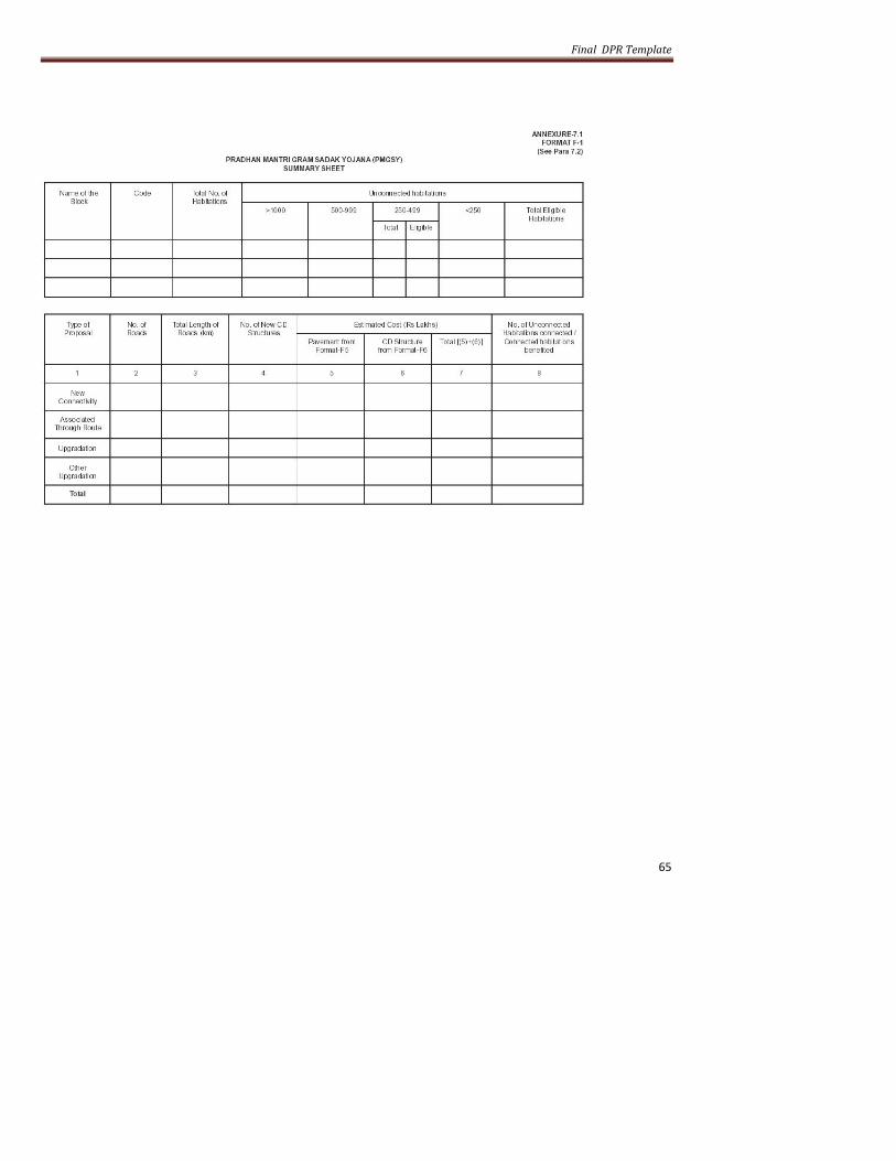
3. Format F1 Package‐wise Summary Sheet
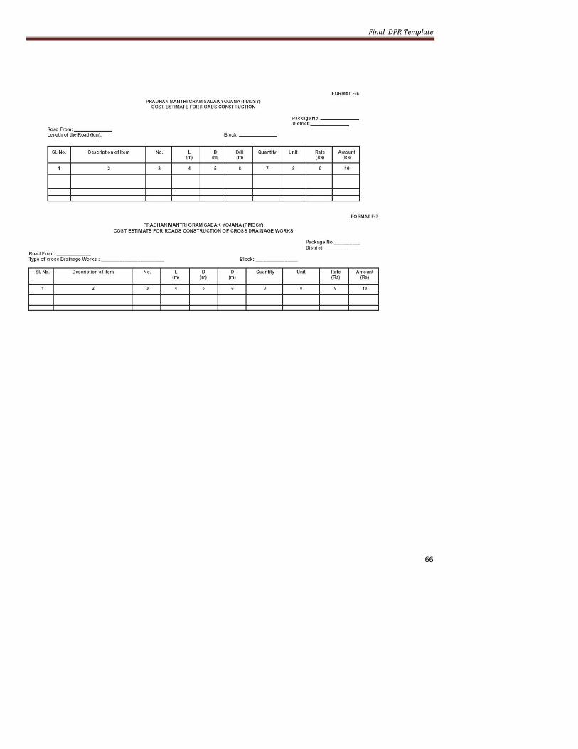
4. Format F6 Cost estimate for Road Construction Works – Pavement Works
5. Format F7 Cost estimate for Cross Drainage Works – Slab Culvert
6. Format F8 Rate of Materials supplied at site – Rate Analysis
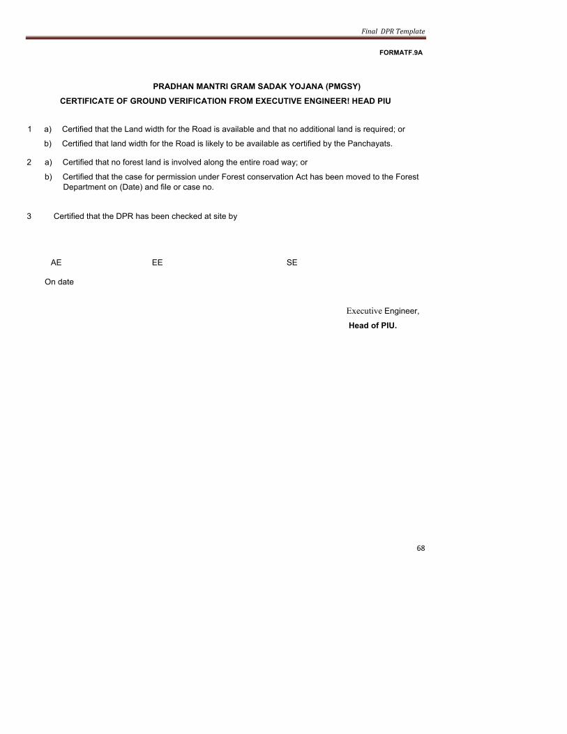
7. Format F9A Certificate of Ground Verification from Executive Engineer / Head of PIU
8. Environmental Checklist
9. Checklist for community consultation on engineering C. List of figures
{Insert list of figures used in this report}
Figure‐1 Road Map of India and state Figure‐2 District Map
Figure‐3 Block Maps showing all existing connectivity like District/block HQ, new townships, National and State highway network, mandis, hospitals, colleges, schools etc.
Figure‐4 Strip plan showing land and alignment details Figure ‐5 Quarry Map
D. Annexure
{Insert list of Annexure provided in this report}
Annexure‐1 Details of soil tests (Section 4.2) Annexure‐2 Detailed hydraulic calculation of all replaced and proposed new culverts
(Section 6.7) Annexure‐3 Chainages‐wise Cut/fill volume Annexure‐4 Transect walk report
Final DPR Template
4
1. Introduction
1.1 Objectives of Pradhan Mantri Gram Sadak Yojana (PMGSY)
Rural Road connectivity is a key component of rural development by promoting access to economic and social services and thereby generating increased agricultural incomes and productive employment opportunities. It is also a key ingredient in ensuring poverty reduction.
It was against this background of poor connectivity that the Prime Minister announced in 2000, a massive rural roads program. The Prime Minister’s Rural Road Program (Pradhan Mantri Gram Sadak Yojana, PMGSY) set a target of:
• Achieving all‐weather road access to every village/habitation with a population greater than 1000 by 2003
• Providing all‐weather road access to all villages/habitations of population greater than 500 people [250 in case of hill States (North‐Eastern states, Sikkim, Himachal Pradesh, Jammu & Kashmir and Uttaranchal), the desert areas and tribal areas] by the end of the Tenth Five Year Plan, i.e., 2007
1.2 All Weather Road
{Insert description of all‐weather roads, duration of interruption on ODRs and VRs.}
1.3 Core Network
The rural road network required for providing the ‘basic access’ to all villages/ habitations is termed as the Core Network. Basic access is defined as one all‐weather road access from each village/ habitation to the nearby Market Centre or Rural Business Hub (RBH) and essential social and economic services. A Core Network comprises of Through Routes and Link Routes. Through routes are the ones which collect traffic from several link roads or a long chain of habitations and lead it to a market centre or a higher category road, i.e. the District Roads or the State or National Highways. Link Routes are the roads connecting a single habitation or a group of habitations to Through Roads or District Roads leading to Market Centres. Link Routes generally have dead ends terminating on habitations, while Through Routes arise from the confluence of two or more Link Routes and emerge on to a major road or to a Market Centre. The Core Network may not represent the most convenient or economic route for all purposes. However, since studies show 85‐90% of rural trips are to market centres, the Core Network is likely to be a cost‐effective conceptual frame work for investment and management purposes, particularly in the context of scarce resources. The Sub‐project road {Insert start of road} to {Insert end of road}, is a link road with Code {Insert Core Network Link /Through Route Code and CNCPL/ CUPL serial number} in {Insert name of block} block of {Insert name of district} District. This road directly connects the habitations of {Insert villages along the road} with populations of {Insert respective population} respectively. Thus this link road serves the total population of {Insert total population served}.
Deleted: code
Final DPR Template
5
1.4 Geography
{Insert a description of the location and geographic features of the area and adjoining land here.}
1.5 Climatic Condition
{Insert a description of the climatic condition of the area here.}
1.6 The Sub‐Project Road
The road passes through plain/rolling/hilly terrain {Delete terrain not applicable}. {Insert a brief description of the geometry of the road, description of whether there are temples, schools, mosques along the alignment, existing cross drainage structures, existing utilities like electric & telephone poles and water lines along the existing road} {Insert description of the discussion with the stakeholders and dwellers regarding donation of land} District: {Insert name of district} Block: {Insert name of block} Road Name: {Insert name of road, strictly as per Core Network} Road Code: {Insert CNCPL code} Package No: {Insert package number} Road Length: {Insert length of road} Km Start Point: {Insert specific latitude and longitude coordinates plus a description
in words} End Point: {Insert specific latitude and longitude coordinates plus a description
in words} Sl.No. Habitation
benefited Population benefited Chainage
Direct Indirect From To {Insert any other description of the project road like table containing habitations served directly to be included here}
Final DPR Template
6
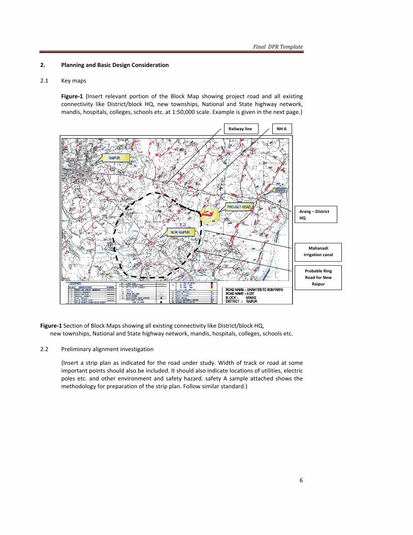
2. Planning and Basic Design Consideration 2.1 Key maps
Figure‐1 {Insert relevant portion of the Block Map showing project road and all existing connectivity like District/block HQ, new townships, National and State highway network, mandis, hospitals, colleges, schools etc. at 1:50,000 scale. Example is given in the next page.}
Figure‐1 Section of Block Maps showing all existing connectivity like District/block HQ, new townships, National and State highway network, mandis, hospitals, colleges, schools etc.
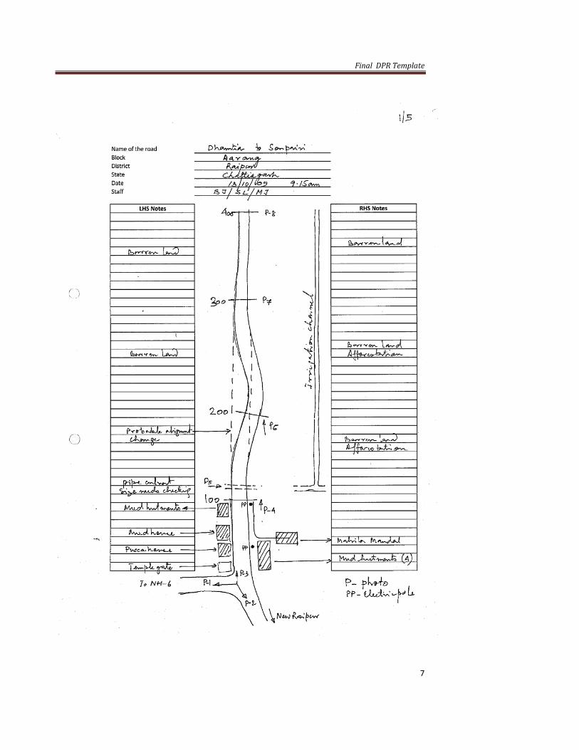
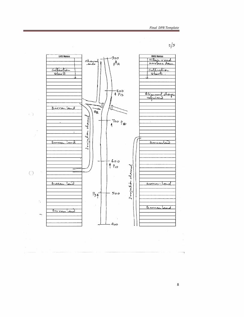
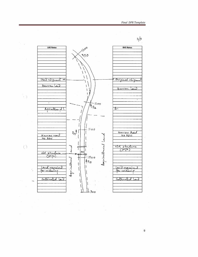
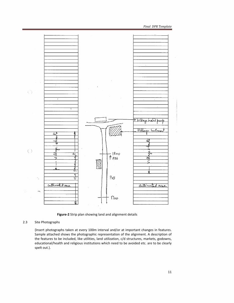
2.2 Preliminary alignment investigation
{Insert a strip plan as indicated for the road under study. Width of track or road at some important points should also be included. It should also indicate locations of utilities, electric poles etc. and other environment and safety hazard. safety A sample attached shows the methodology for preparation of the strip plan. Follow similar standard.}
NH‐6Railway line
Mahanadi irrigation canal
Arang – District HQ
Probable Ring Road for New
Raipur
Final DPR Template
7
Final DPR Template
8
Final DPR Template
9

Final DPR Template
10
Final DPR Template
11
Figure‐2 Strip plan showing land and alignment details
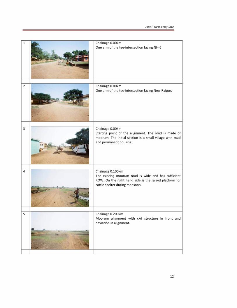
2.3 Site Photographs
{Insert photographs taken at every 100m interval and/or at important changes in features. Sample attached shows the photographic representation of the alignment. A description of the features to be included, like utilities, land utilization, c/d structures, markets, godowns, educational/health and religious institutions which need to be avoided etc. are to be clearly spelt out.}.
Final DPR Template
12
1
Chainage 0.00km One arm of the tee‐intersection facing NH‐6
2
Chainage 0.00km One arm of the tee‐intersection facing New Raipur.
3
Chainage 0.00km Starting point of the alignment. The road is made of moorum. The initial section is a small village with mud and permanent housing.
4
Chainage 0.100km The existing moorum road is wide and has sufficient ROW. On the right hand side is the raised platform for cattle shelter during monsoon.
5
Chainage 0.200km Moorum alignment with c/d structure in front and deviation in alignment.
Final DPR Template
13
6
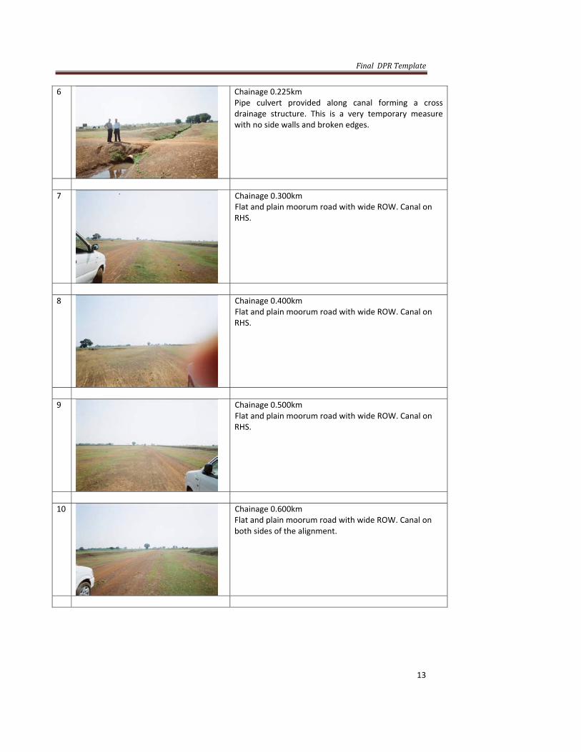
Chainage 0.225km Pipe culvert provided along canal forming a cross drainage structure. This is a very temporary measure with no side walls and broken edges.
7
Chainage 0.300km Flat and plain moorum road with wide ROW. Canal on RHS.
8
Chainage 0.400km Flat and plain moorum road with wide ROW. Canal on RHS.
9
Chainage 0.500km Flat and plain moorum road with wide ROW. Canal on RHS.
10
Chainage 0.600km Flat and plain moorum road with wide ROW. Canal on both sides of the alignment.
Final DPR Template
14
11
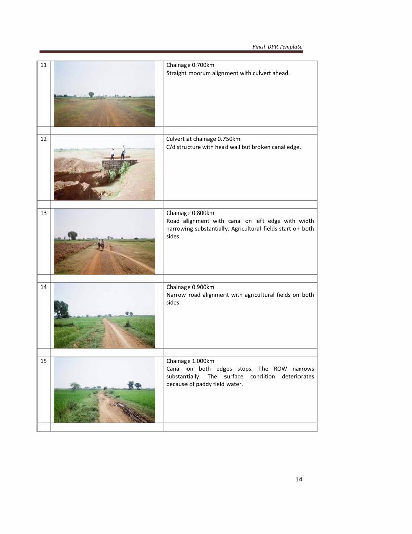
Chainage 0.700km Straight moorum alignment with culvert ahead.
12
Culvert at chainage 0.750km C/d structure with head wall but broken canal edge.
13
Chainage 0.800km Road alignment with canal on left edge with width narrowing substantially. Agricultural fields start on both sides.
14
Chainage 0.900km Narrow road alignment with agricultural fields on both sides.
15
Chainage 1.000km Canal on both edges stops. The ROW narrows substantially. The surface condition deteriorates because of paddy field water.
Final DPR Template
15
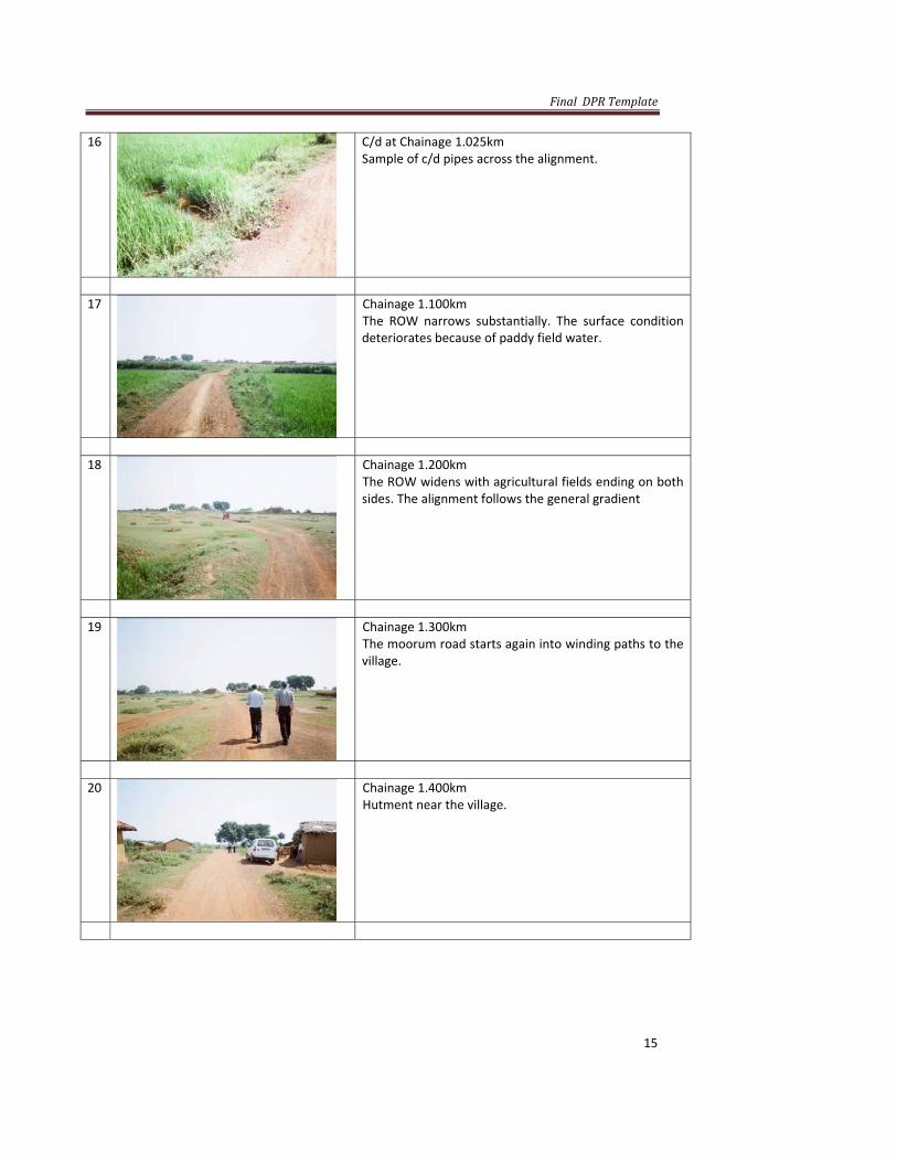
16
C/d at Chainage 1.025km Sample of c/d pipes across the alignment.
17
Chainage 1.100km The ROW narrows substantially. The surface condition deteriorates because of paddy field water.
18
Chainage 1.200km The ROW widens with agricultural fields ending on both sides. The alignment follows the general gradient
19
Chainage 1.300km The moorum road starts again into winding paths to the village.
20
Chainage 1.400km Hutment near the village.
Final DPR Template
16
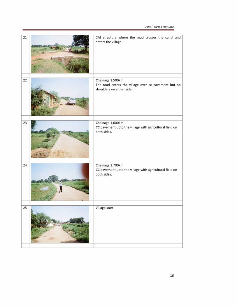
21
C/d structure where the road crosses the canal and enters the village.
22
Chainage 1.500km The road enters the village over cc pavement but no shoulders on either side.
23
Chainage 1.600km CC pavement upto the village with agricultural field on both sides.
24
Chainage 1.700km CC pavement upto the village with agricultural field on both sides.
25
Village start

Final DPR Template
17
2.4 Road Design Brief
{Insert a tabular format (sample attached) giving the design issues and solutions to be used by the Consultants in finalizing the drawings, provision of c/d structures, land acquisition issues, drainage issues, etc., approx. distance from existing centre line will be of use and have to be clearly spelt out in this table.}
Table 2.1 Road Design Brief (example attached)
26
Chainage 1.800km End of the alignment at a village water hand pump.
Sl. Location Issue Design Solutions 1 Ch. 0.00km The proposed road is connecting New
Raipur and Arang the block HQ. The road starts with a Tee intersection. While New Raipur gets developed there will be substantial traffic using this road. Electricity poles are located along the alignment.
The intersection needs to be developed properly for safety. The electricity poles need to be relocated.
2 Ch.0.100 to 0.300 km
The section has a pipe laid across the road without any head wall or foundation. This is for the water from the irrigation channels for cross flow. This causes soil erosion in the channel. Because of the pipe the alignment has been adjusted in skew.
Proper cross drainage structure to be provided. The road has to be realigned.
3 Ch. 0.700 to 0.900 km
Because of the skew in channel alignment the road has been skewed. The channel walls have eroded due to flow of water.
The alignment has to be readjusted. The channel walls need to be protected from erosion.
4 Ch. 0.900 to 1.200 km
Due to agricultural cultivation the road has only the c/w and no shoulders.
Land acquisition/donation will be required to provide for c/w and shoulder. It also needs to be raised to avoid water logging.
5 Ch. 1.200 to 1.300 km
The foot track is different from the actual vehicle path provided.
Curve needs to be properly designed.
7 Ch. 1.400km The culvert provided skews the alignment.
The culvert has to be redesigned so that proper geometry can be provided to the alignment.
8 Ch. 1.400 to 1.860 km
The cc pavement does not have any shoulder. This is very risky for vehicles
Proper shoulder to be provided on either side.
Final DPR Template
18
2.5 Transect Walk Summary
{Insert a tabular format (sample attached) giving the summary of the transect walk and giving the issues identified and solutions proposed by the affected communities.}
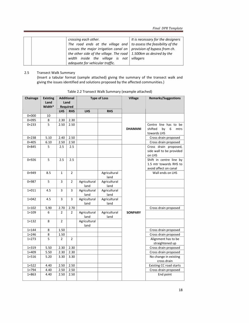
Table 2.2 Transect Walk Summary (example attached)
crossing each other. The road ends at the village and crosses the major irrigation canal on the other side of the village. The road width inside the village is not adequate for vehicular traffic.
It is necessary for the designers to assess the feasibility of the provision of bypass from ch. 1.500km as desired by the villagers
Additional Land
Required
Type of Loss Chainage Existing Land
Width* LHS RHS LHS RHS
Village Remarks/Suggestions
0+000 10 0+095 8 2.30 2.30
0+233 5 2.50 2.50 Centre line has to be shifted by 6 mtrs towards LHS
0+238 5.10 2.40 2.50 Cross drain proposed 0+405 6.10 2.50 2.50
DHAMANI
Cross drain proposed 0+845 5 2.5 2.5 Cross drain proposed,
side wall to be provided on LHS
0+926 5 2.5 2.5 Shift in centre line by 1.5 mtr towards RHS to avoid affect on canal
0+949 8.5 1 2 Agricultural land
Wall ends on LHS
0+987 5 3 2 Agricultural land
Agricultural land
1+011 4.5 3 3 Agricultural land
Agricultural land
1+042 4.5 3 3 Agricultural land
Agricultural land
1+102 5.90 2.70 2.70 Cross drain proposed 1+109 6 2 2 Agricultural
land Agricultural
land
1+132 8 2 Agricultural land
1+144 8 1.50 Cross drain proposed 1+246 8 1.50 Cross drain proposed 1+273 5 2 2 Alignment has to be
straightened up 1+319 5.50 2.30 2.30 Cross drain proposed 1+409 5.50 2.30 2.30 Cross drain proposed 1+516 5.20 3.30 3.30 No change in existing
cross drain 1+522 4.40 2.50 2.50 Existing CC road starts 1+794 4.40 2.50 2.50 Cross drain proposed 1+863 4.40 2.50 2.50
SONPARY
End point
Final DPR Template
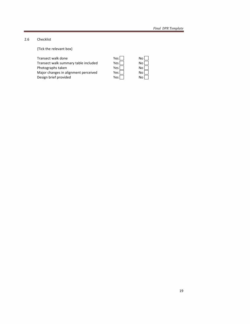
19
2.6 Checklist {Tick the relevant box} Transect walk done Yes No Transect walk summary table included Yes No Photographs taken Yes No Major changes in alignment perceived Yes No Design brief provided Yes No
Final DPR Template
20
3. Topographic Survey
3.1 General
Topographic survey true to ground realties have been done using {Delete method not used: precision instruments like total stations and auto levels, and bringing out data in digital form (x,y,z format) for developing digital terrain model (DTM) or plane table survey and using dumpy level for leveling survey}.
The in‐house standards, work procedures and quality plan prepared with reference to IRC: SP 19‐2001, IRC: SP 20, IRC: SP 13 (in respect of surveys for rivers/streams) and current international practices have been followed during the above survey.
3.2 Traversing
Traverse has been done by total station having angular measurement accuracy of ± 1 sec.
{Insert a brief methodology of traverse survey}
3.3 Leveling
{Insert a brief methodology of leveling survey, accuracy adopted, nearest bench mark etc.}
3.4 Cross Section & Detailing
Cross sections were taken at 30 m interval and at closer interval in curved portion of the existing road. All physical features of the road were recorded.
{Generally, cross section will be taken at every 30m interval. In case of any major variation in the long section cross sections have to be taken irrespective of the 30m interval. The cross section details are to be taken for a further distance of half the formation width beyond the shoulders on either side of the road.}
3.5 Data Processing
All data from topographic survey recorded by total station were downloaded and final alignment, plan, profile were prepared and presented in AutoCAD Format.
3.6 {Insert List of permanent reference pillars and TBMs including northing easting and levels}
3.7 Checklist
{Tick the relevant box} Reference pillars given Yes No TBM with northing‐easting given Yes No Traverse survey carried out Yes No Cross section and detailing carried out Yes No
Final DPR Template
21
4. Soil and Materials Survey
4.1 General
The soil and material investigations were done following the guidelines of IRC: SP: 20‐2002 and IRC: SP: 72‐2007 and other relevant IS codes. The potential sources of borrow areas for soil and quarry sites will be identified.
4.2 Soil sample collection and Testing
Soil samples will be collected along and around the road alignment at three (3) locations per km, from the adjoining borrow areas, as well as one sample is collected from the existing road. Soil Classification tests like grain size analysis and Atterberg’s limit were conducted for all the samples collected. Standard Proctor test and the corresponding 4 day soaked CBR test were conducted either for a minimum of one test per km for soil samples of same group or more tests due to variation of soil type. The following tests were conducted as detailed below:
• Grain size analysis as per IS : 272 (Part 4) – 1985 • Atterberg’s limit as per IS : 2720 (Part 5) – 1985 • Standard Proctor density test as per IS : 2720 (Part 7) – 1980 • 4 day soaked CBR test as per IS : 2720 (Part 16) – 1985
{The IRC Rural Roads Manual SP: 20 contain instructions on Soil Survey and materials for the road projects. Supplementary guidance on these subjects is given in Annexure 5.1.The identification of the soil type in the field and the quick determination of its properties, including CBR are the basic requirement for an economical pavement design. The grain‐size (wet sieve) analysis leading to the soil classification is a simple test and must be carried out to have an idea of the CBR value with a reasonable level of accuracy; the nomograph given in Annexure 5.2 can be used. This would minimise the need for CBR determination in lab. The determination of CBR by a rigorous CBR apparatus on a large number of samples may not be possible unless properly planned, and hence the nomograph given in Annexure 5.2 may be used.} {Insert the details of soil tests in Annexure‐1}
4.3 Analysis of Test Results
The laboratory soaked CBR value ranges from ……..% to ……..% {Insert range}. The soil laboratory test results will be summarized in Table 4.1 {Insert the summary of soil test results in table}
Table 4.1 CBR values for different stretches Sl.No. Section CBR (%)
4.4 Coarse and Fine Aggregates
Information regarding the source of aggregate and sand will be gathered. The stone aggregates shall be procured from {Insert name of quarry} where as the locally available sand shall be used. The source and the lead distance from the quarry to project site will be finalized in discussion with the PIU. The aggregates and sand where available and acceptable shall be used for bituminous work, concrete works, other pavement works.
Figure ‐3 Quarry Map {Insert the quarry map}
Final DPR Template
22
4.5 Sub‐soil investigation for bridges
{Insert a brief write‐up on methodology and location of sub‐soil investigation, codes followed and brief results thereof. Detailed bore logs, test results should given at the end of the report}
4.6 Checklist
{Tick the relevant box} Borrow pit suitable Yes No SSI for existing ground Yes No Investigation for coarse/fine aggregate Yes No Quarry map Yes No
Final DPR Template
23
5. Traffic Survey
5.1 General
{In addition to traffic counts on the project road, traffic counts must be taken on already completed or similar type of PMGSY road in the vicinity of the project road to provide a realistic count.} In the present scenario of new connectivity/upgradation road, 3 day, 24 hr traffic volume count has been conducted on the already completed or similar type of PMGSY road in the vicinity of the project road. The Classified Volume Count survey has been carried out in accordance with the requirements of the TOR and relevant codes (IRC: SP: 19‐2001, IRC: SP: 20, IRC: SP: 72‐2007).The surveys have been carried out by trained enumerators manually under the monitoring of Engineering Supervisor. {Insert description of traffic count locations. Explain why nearby road is similar to expected post construction situation of the project road. Insert map showing project road and similar road and locations of traffic counts.}
5.2 Traffic Data and Analysis
The traffic count done was classified into different vehicle category as given below:
• Motorized vehicle comprising of light commercial vehicle, medium commercial vehicle, heavy commercial vehicle, trucks, buses, agricultural tractors with trailers, car, jeep, two wheelers etc.
• Non‐ motorized vehicles comprising of cycle, rickshaw, cycle van, animal drawn vehicle etc.
The number of laden and un‐laden commercial vehicles was recorded during the traffic counts. Traffic volume count for this project road was done during {insert season} season. The seasonal variation {insert seasonal variation} is based on local enquiry.
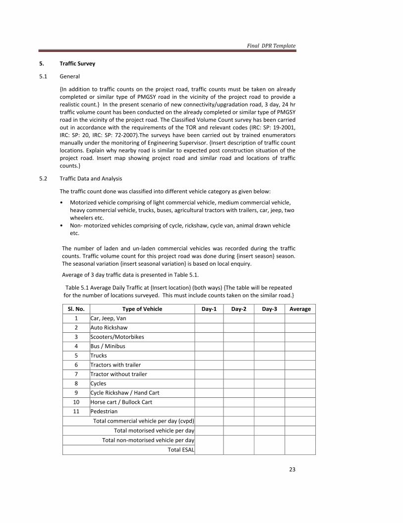
Average of 3 day traffic data is presented in Table 5.1.
Table 5.1 Average Daily Traffic at {Insert location} (both ways) {The table will be repeated for the number of locations surveyed. This must include counts taken on the similar road.}
Sl. No. Type of Vehicle Day‐1 Day‐2 Day‐3 Average
1 Car, Jeep, Van
2 Auto Rickshaw
3 Scooters/Motorbikes
4 Bus / Minibus
5 Trucks
6 Tractors with trailer
7 Tractor without trailer
8 Cycles
9 Cycle Rickshaw / Hand Cart
10 Horse cart / Bullock Cart
11 Pedestrian
Total commercial vehicle per day (cvpd)
Total motorised vehicle per day
Total non‐motorised vehicle per day
Total ESAL
Final DPR Template
24
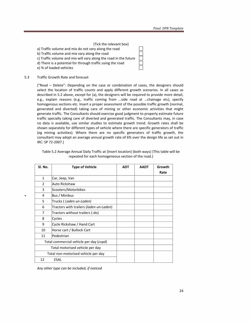
{Tick the relevant box}
a) Traffic volume and mix do not vary along the road b) Traffic volume and mix vary along the road c) Traffic volume and mix will vary along the road in the future d) There is a potential for through traffic using the road e) % of loaded vehicles
5.3 Traffic Growth Rate and forecast
{“Read – Delete”: Depending on the case or combination of cases, the designers should select the location of traffic counts and apply different growth scenarios. In all cases as described in 5.2 above, except for (a), the designers will be required to provide more detail, e.g., explain reasons (e.g., traffic coming from …side road at …chainage etc), specify homogenous sections etc. Insert a proper assessment of the possible traffic growth (normal, generated and diverted) taking care of mining or other economic activities that might generate traffic. The Consultants should exercise good judgment to properly estimate future traffic specially taking care of diverted and generated traffic. The Consultants may, in case no data is available, use similar studies to estimate growth trend. Growth rates shall be shown separately for different types of vehicle where there are specific generators of traffic (eg mining activities). Where there are no specific generators of traffic growth, the consultant may adopt an average annual growth rate of 6% over the design life as set out in IRC: SP 72‐2007.}
Table 5.2 Average Annual Daily Traffic at {Insert location} (both ways) {This table will be repeated for each homogeneous section of the road.}
*
Any other type can be included, if noticed
Sl. No. Type of Vehicle ADT AADT Growth Rate
1 Car, Jeep, Van
2 Auto Rickshaw
3 Scooters/Motorbikes
4 Bus / Minibus
5 Trucks ( Laden un‐Laden)
6 Tractors with trailers (laden un‐Laden)
7 Tractors without trailers (‐do)
8 Cycles
9 Cycle Rickshaw / Hand Cart
10 Horse cart / Bullock Cart
11 Pedestrian
Total commercial vehicle per day (cvpd)
Total motorised vehicle per day
Total non‐motorised vehicle per day
12 ESAL

Final DPR Template
25
6. Hydrological Survey
6.1 General
Hydrological survey is necessary for design of adequate and safe Cross Drainage Structures so that the rain water can pass as per natural slope. Hydrological survey of the proposed road is based on the following observations:
• Rainfall Data • Catchments Area • Time of Concentration • Existing Cross Drainage Structures
6.2 Rainfall Data
Rainfall Data as applicable for the project road were collected with maximum rainfall occurring in the months of {insert months}.
6.3 Catchment Area
The Catchments area is calculated by gathering local information and topographical survey data as it was not possible to calculate from topographical sheets due to their unavailability.
6.4 Time of Concentration
Time of concentration (tc) in hours is calculated from the formula of (0.87 x L3/H)
0.385, where
L is distance from the critical point to the structure site in km and H is the difference in elevation between the critical point and the structure site in meters.
6.5 Existing Cross Drainage Structures
There are {Insert the number of c/d structures} number of cross drainage structures along the existing project road as listed below:
{Insert the data in the table below}
Table‐6.1 List and condition of existing culverts Sl. Chainage (km) Description of Existing Structure Type Span/ Dia. (m) Condition
Final DPR Template
26
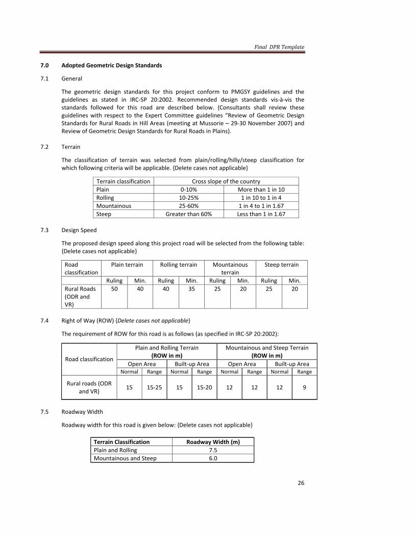
7.0 Adopted Geometric Design Standards
7.1 General
The geometric design standards for this project conform to PMGSY guidelines and the guidelines as stated in IRC‐SP 20:2002. Recommended design standards vis‐à‐vis the standards followed for this road are described below. {Consultants shall review these guidelines with respect to the Expert Committee guidelines “Review of Geometric Design Standards for Rural Roads in Hill Areas (meeting at Mussorie – 29‐30 November 2007) and Review of Geometric Design Standards for Rural Roads in Plains}.
7.2 Terrain
The classification of terrain was selected from plain/rolling/hilly/steep classification for which following criteria will be applicable. {Delete cases not applicable}
Terrain classification Cross slope of the country Plain 0‐10% More than 1 in 10 Rolling 10‐25% 1 in 10 to 1 in 4 Mountainous 25‐60% 1 in 4 to 1 in 1.67 Steep Greater than 60% Less than 1 in 1.67
7.3 Design Speed
The proposed design speed along this project road will be selected from the following table: {Delete cases not applicable}
Road classification
Plain terrain Rolling terrain Mountainous terrain
Steep terrain
Ruling Min. Ruling Min. Ruling Min. Ruling Min. Rural Roads (ODR and VR)
50 40 40 35 25 20 25 20
7.4 Right of Way (ROW) {Delete cases not applicable}
The requirement of ROW for this road is as follows (as specified in IRC‐SP 20:2002):
Plain and Rolling Terrain (ROW in m)
Mountainous and Steep Terrain (ROW in m)
Open Area Built‐up Area Open Area Built‐up Area Road classification
Normal Range Normal Range Normal Range Normal Range
Rural roads (ODR and VR)
15 15‐25
15
15‐20 12 12 12 9
7.5 Roadway Width
Roadway width for this road is given below: {Delete cases not applicable}
Terrain Classification Roadway Width (m) Plain and Rolling 7.5 Mountainous and Steep 6.0
Final DPR Template
27
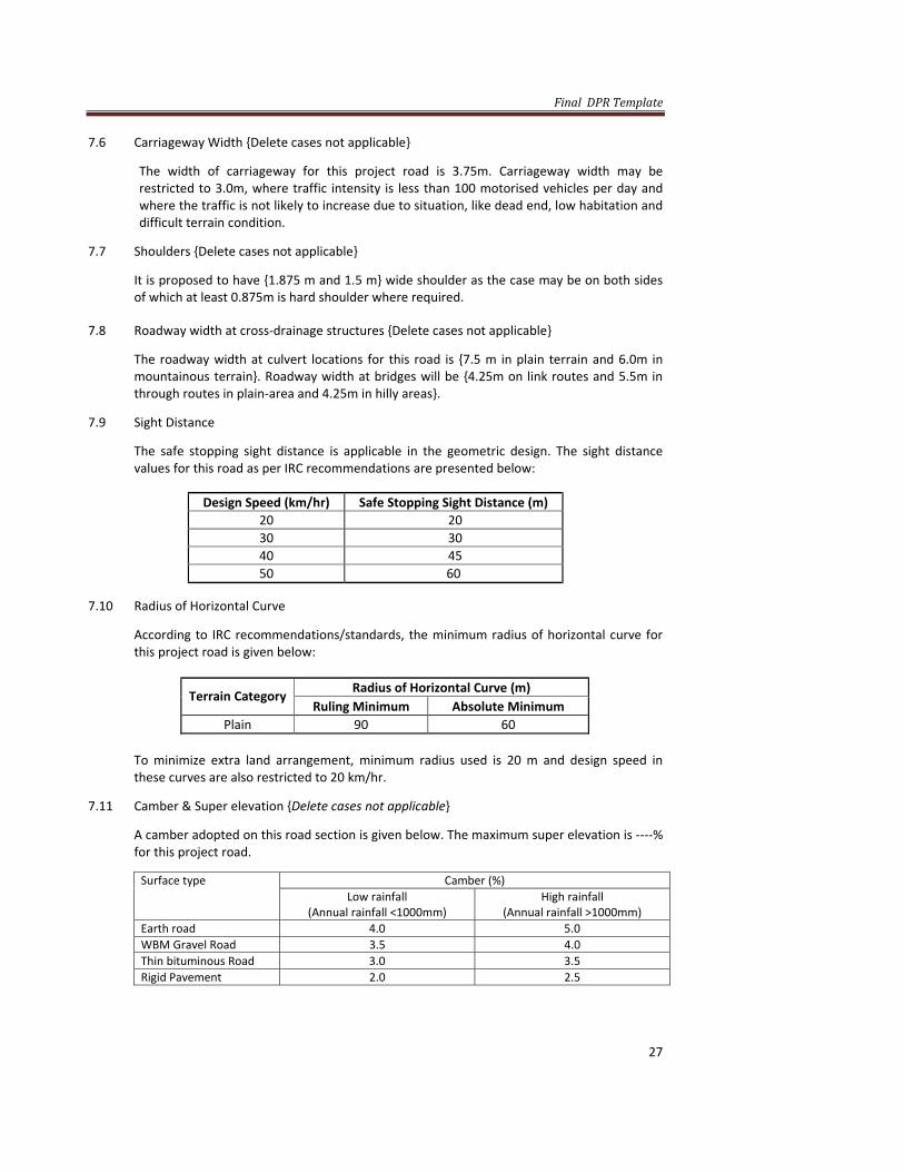
7.6 Carriageway Width {Delete cases not applicable}
The width of carriageway for this project road is 3.75m. Carriageway width may be restricted to 3.0m, where traffic intensity is less than 100 motorised vehicles per day and where the traffic is not likely to increase due to situation, like dead end, low habitation and difficult terrain condition.
7.7 Shoulders {Delete cases not applicable}
It is proposed to have {1.875 m and 1.5 m} wide shoulder as the case may be on both sides of which at least 0.875m is hard shoulder where required.
7.8 Roadway width at cross‐drainage structures {Delete cases not applicable}
The roadway width at culvert locations for this road is {7.5 m in plain terrain and 6.0m in mountainous terrain}. Roadway width at bridges will be {4.25m on link routes and 5.5m in through routes in plain‐area and 4.25m in hilly areas}.
7.9 Sight Distance
The safe stopping sight distance is applicable in the geometric design. The sight distance values for this road as per IRC recommendations are presented below:
7.10 Radius of Horizontal Curve
According to IRC recommendations/standards, the minimum radius of horizontal curve for this project road is given below:
Radius of Horizontal Curve (m)
Terrain Category Ruling Minimum Absolute Minimum
Plain 90 60 To minimize extra land arrangement, minimum radius used is 20 m and design speed in these curves are also restricted to 20 km/hr.
7.11 Camber & Super elevation {Delete cases not applicable}
A camber adopted on this road section is given below. The maximum super elevation is ‐‐‐‐% for this project road.
Camber (%) Surface type Low rainfall
(Annual rainfall <1000mm) High rainfall
(Annual rainfall >1000mm) Earth road 4.0 5.0 WBM Gravel Road 3.5 4.0 Thin bituminous Road 3.0 3.5 Rigid Pavement 2.0 2.5
Design Speed (km/hr) Safe Stopping Sight Distance (m) 20 20 30 30 40 45 50 60
Final DPR Template
28
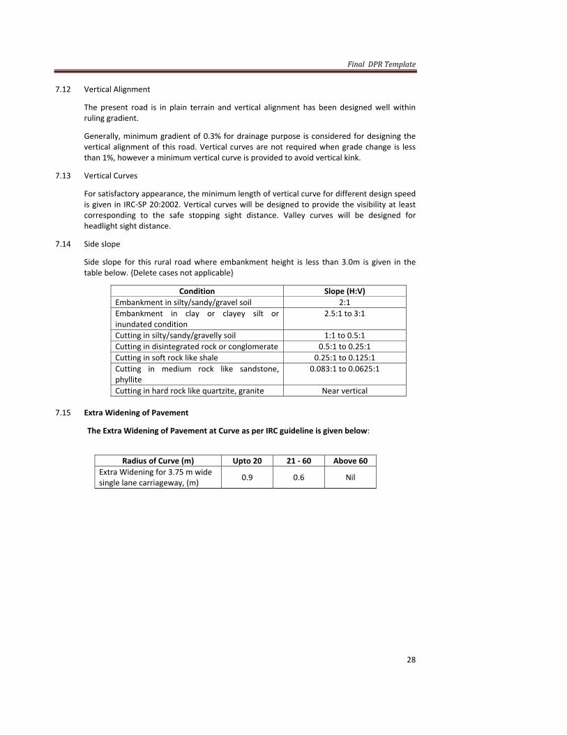
7.12 Vertical Alignment
The present road is in plain terrain and vertical alignment has been designed well within ruling gradient.
Generally, minimum gradient of 0.3% for drainage purpose is considered for designing the vertical alignment of this road. Vertical curves are not required when grade change is less than 1%, however a minimum vertical curve is provided to avoid vertical kink.
7.13 Vertical Curves
For satisfactory appearance, the minimum length of vertical curve for different design speed is given in IRC‐SP 20:2002. Vertical curves will be designed to provide the visibility at least corresponding to the safe stopping sight distance. Valley curves will be designed for headlight sight distance.
7.14 Side slope
Side slope for this rural road where embankment height is less than 3.0m is given in the table below. {Delete cases not applicable}
Condition Slope (H:V) Embankment in silty/sandy/gravel soil 2:1 Embankment in clay or clayey silt or inundated condition
2.5:1 to 3:1
Cutting in silty/sandy/gravelly soil 1:1 to 0.5:1 Cutting in disintegrated rock or conglomerate 0.5:1 to 0.25:1 Cutting in soft rock like shale 0.25:1 to 0.125:1 Cutting in medium rock like sandstone, phyllite
0.083:1 to 0.0625:1
Cutting in hard rock like quartzite, granite Near vertical
7.15 Extra Widening of Pavement
The Extra Widening of Pavement at Curve as per IRC guideline is given below:
Radius of Curve (m) Upto 20 21 ‐ 60 Above 60 Extra Widening for 3.75 m wide single lane carriageway, (m)
0.9 0.6 Nil
Final DPR Template
29
8. Alignment Design 8.1 General
The basic aim of highway design is to identify technically sound, environment‐friendly and economically feasible highway alignment. The ensuing sections deals with obligatory points, which control highway alignment, design of cross‐section, highway geometric design & methodology, design of miscellaneous items.
The main components included in the highway design are:
Cross‐sectional elements Embankment Horizontal alignment Vertical profile Junctions and/or Interchanges Road furniture Miscellaneous items
8.2 Horizontal alignment
{Insert a table (example given below) on the physical features of the existing alignment and possible geometric improvement required}
Table 8.1 – Features of Horizontal Alignment (Example)
Chainage Length
From (km) To (km) (km) Description
Reason for deviation from existing alignment, if
necessary
Checklist
{Tick the relevant box}
a) Centre line of the existing and proposed horizontal alignment coincide
b) Centre line of the existing and proposed horizontal alignment deviate at certain sections
{Where the proposed horizontal alignment deviates from the centreline of the existing alignment, and where the clearance of the proposed horizontal alignment from existing roadside features (eg houses, temples, ponds, etc) is very tight, the horizontal alignment plan shall be drawn at large scale in the drawing set. }

Final DPR Template
30
{Insert a schematic diagram showing linear offsets from existing alignment as example attached}
Chainage LHS Existing alignment
RHS Chainage shift
Approx land required (m)
2.20 2.20
2.10
2.00
1.90
1.80
1.70 1.65
1.60
1.50 1.43
1.40
1.30
1.20
1.10
1.00 0.97
0.90
0.80
0.70
0.60
0.50 0.46
0.40
0.30
0.20
0.10
0.00 0.00
Figure 8.1 Schematic diagram showing location and offsets from existing alignment
Final DPR Template
31
{Insert a table (example given below) on the various horizontal geometric improvement carried out and their details}
Table 8.2 – Horizontal Curve details (Example)
Radius Ls Speed Def Angle Lc Ltotal Hand
of Curve
Curve No.
IP Chainage
(m) (m) (Kmph)
S.E.
D M S (m) (m)
8.3 Vertical alignment
{Insert a table (example given below) on the various vertical geometric improvement carried out and their details}
Table 8.3 – Vertical Curve Details (Example)
Leve
l of p
vi
Leng
th o
f cu
rve
Type
of c
urve
Gra
de in
(%)
Gra
de o
ut (%
)
Gra
de
diff
eren
ce (%
)
Chai
nage
Leve
l
Sl. NO.
Chainage (m)
St. o
f Cur
ve
End
of C
urve
St. o
f Cur
ve
End
of C
urve
1 2 3
8.4 Design of Junctions
The proposed alignment intersects cross roads and forms junctions. The locations of junctions are given below:
{Insert location of important junctions, type and any major intersections improvement proposed.}
Table 8.4 – List intersections, type and proposed modifications
Sl. Type of intersection
Location (km)
Exiting condition Proposed modification
Final DPR Template
32
9. Pavement Design
9.1 General
Considering the sub‐grade strength, projected traffic and the design life, the pavement design for low volume PMGSY roads was carried out as per guidelines of IRC: SP: 72 – 2007, or IRC SP:77 “Design of Gravel Road” and IRC SP:62‐2004 “Cement Concrete roads”. In built up area for hygienic and safety reasons, C.C. pavement was used with a hard shoulder and drain appropriate line drain. {Delete the last line if CC pavement was not provided}.
9.2 Pavement Design Approach
9.2.1 Design Life
A design life of 10 years was considered for the purpose of pavement design of flexible and granular pavements.
9.2.2 Design Traffic
The average annual daily traffic (AADT) for the opening year as well as the total commercial vehicle per day (CVPD) was presented in Table 5.2.
9.2.3 Determination of ESAL applications
Only commercial vehicles with a gross laden weight of 3 tonnes or more are considered. The design traffic was considered in terms of cumulative number of standard axles to be carried during the design life of the road. The numbers of commercial vehicles of different axle loads are converted to number of standard axle repetitions by a multiplier called the Vehicle Damage Factor (VDF). An indicative VDF value was considered as the traffic volume of rural road does not warrant axle load survey.
For calculating the VDF, the following categories of vehicles was considered as suggested in paragraph 3.4.4 of IRC: SP: 72 – 2007.
• Laden heavy/medium commercial vehicles • Un‐laden /partially loaded heavy/medium commercial vehicles • Over loaded heavy/medium commercial vehicles
Indicative VDF values considered 10% of laden MCV and 10% laden HCV as overloaded & given below:
Lane distribution factor (L) for Single lane road = 1.0 Cumulative ESAL application = To x 4811 x L, where To = ESAL application per day. The Cumulative ESAL application for the project road as per paragraph 3.5 of IRC: SP: 72 – 2007 is presented in Annexure {Insert Annexure number}
9.2.4 Subgrade CBR
The subgrade CBR range of {Insert CBR % range} was considered and the traffic falls in the {Insert traffic classification} category.
Vehicle type Laden Un‐laden /Partially laden HCV 2.86 0.31 MCV 0.34 0.02
Final DPR Template
33
9.3 Design Alternatives
{Insert design alternatives like flexible vs. rigid pavement and paved vs. normal shoulders}
Design alternatives considered {tick the applicable box}
Chainage Design alternatives considered Pavement Shoulder
From To
Flex
ible
Rigi
d
Eart
hen
full
wid
th
Har
d Fu
ll w
idth
Har
d sh
ould
er
0.87
5 m
eac
h si
de
Soil
stab
iliza
tion
and
use
of lo
cally
av
aila
ble
mar
gina
l m
ater
ials
.
Specify design
alternative selected Ju
stifi
catio
n
9.4 Pavement composition
Flexible Pavement The designed pavement thickness and composition was calculated by referring Figure 4 (Pavement design catalogue) of IRC: SP: 72 – 2007. The ratio between heavy commercial vehicles and medium commercial vehicles as given in Chapter 5 should be maintained as far as possible. The pavement layers provided are given below:
Top layer of WBM will be treated with bituminous surface. {If the pavement thickness varies over the entire length of the road section a table showing different thickness adopted should be given.}
Rigid Pavement
{Insert cc pavement design as per IRC:SP:62‐2004 wherever provided, if not delete}
9.5 Embankment Design
{Insert embankment design for high embankments (above 6m) especially at bridge approaches. Related soil investigations need to be done for borrow earth and existing ground}
Top Layer Premix Carpet with Type B Seal Coat {Insert thickness} mm Base Layer WBM Grading III & WBM Grading II {Insert thickness} mm Sub – Base Layer Granular Sub‐base Grading II {Insert thickness} mm Total thickness {Insert thickness} mm
Final DPR Template
34
10. Design of Cross Drainage Works
10.1 General
On the basis of hydrological survey, {Insert number of new cross drainage works} new cross drainage structures are recommended for the project road as listed below. {Consultants shall review these guidelines with respect to the Expert Committee guidelines “Review of Geometric Design Standards for Rural Roads in Hill Areas (meeting at Mussorie – 29‐30 November 2007) and Review of Geometric Design Standards for Rural Roads in Plains}
10.2 Hydrological Design
The existing structures in poor condition that are proposed for replacement as listed below. Agricultural conduits, which basically act as balancers, have also been provided as listed below in Table 10.2.
10.3 Design Feature
Design Standards for culverts has been prepared based on standard codes and guidelines of IRC: SP: 20: 2002 and similar type of ongoing projects. General features of the designed cross drainage structures are given below:
For hume pipe culvert, minimum road width has been taken as {xx} m, Width of culvert : {xx} m with parapet. Width of Bridge: {xx} m with parapet.
10.4 Justification for retaining/widening and replacement of culverts
{Insert the design considerations developed after the transect walk}
10.5 Hydraulic calculation for Culvert
The design discharge was calculated by the rational method considering peak runoff from catchment using the formula,
Q = 0.028 x P x A xIc
Where P = Coefficient of Run Off for the catchments characteristics, A = Catchments Area in Hectares & Ic = Rainfall Intensity
Small bridge‐site length of which exceeds 15 m to be jointly visited by STA and S.E. Design – as per SP‐20 & SP‐13 and relevant IRC Codes for Bridges.
Causeways and submersible bridges – Design to be done as per SP‐20 and SP‐82:2005.
{Insert detailed hydraulic calculation of all replaced and proposed new culverts and attached as Annexure‐2 of this report}.
Final DPR Template
35
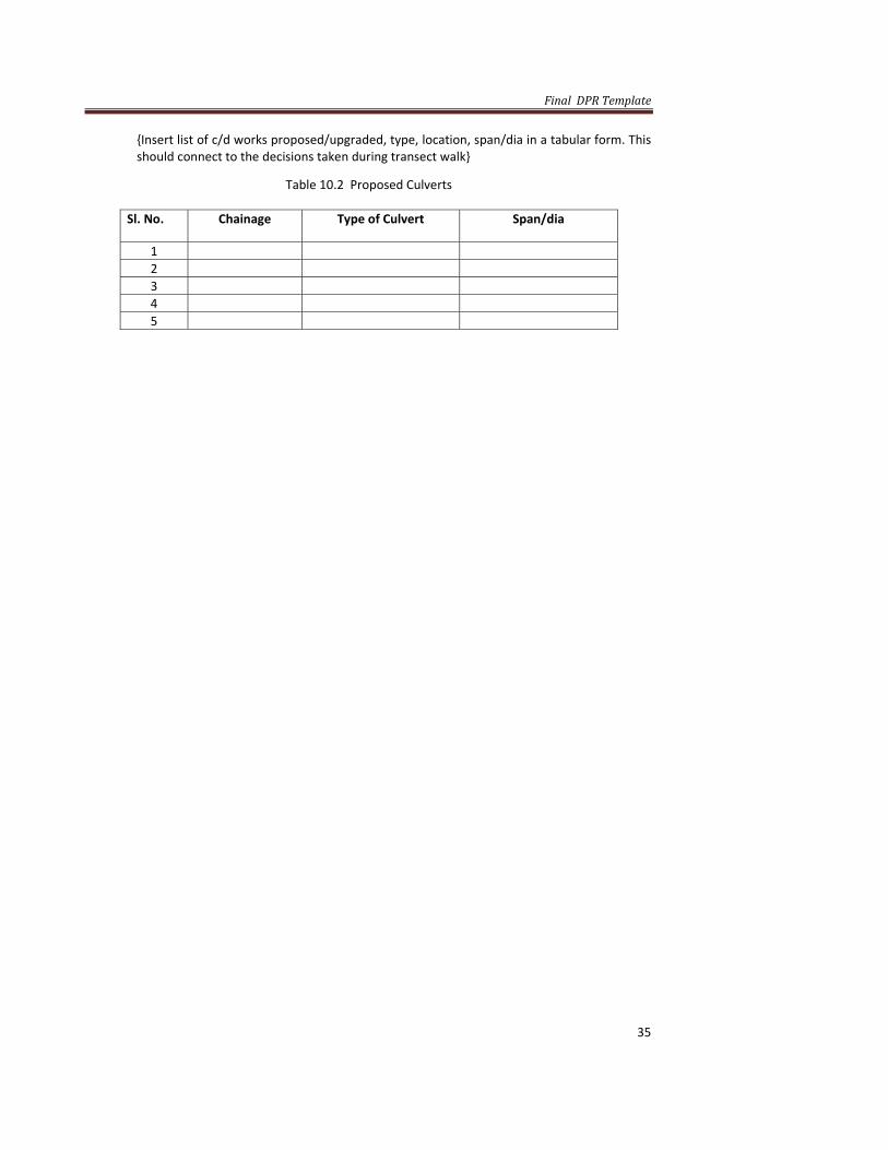
{Insert list of c/d works proposed/upgraded, type, location, span/dia in a tabular form. This should connect to the decisions taken during transect walk}
Table 10.2 Proposed Culverts
Sl. No. Chainage Type of Culvert Span/dia
1 2 3 4 5

Final DPR Template
36
11. Protective Works & Drainage
11.1 General
{Insert necessary description of the terrain and drainage condition along the road under study}
11.2 Road side drain
As the insufficient drainage of surface water leads to rapid damage of road, road side drain as shown in drawing volume has been provided particularly on the location of habitation areas. Sketch for a standard roadside drain should be made available, confirming to any of the sections suggested in SP:20:2002.
11.3 Protective Works
Necessary protection works consisting of closed {Insert type of pilling} piling and {Insert ballah suggested} ballah piling/ Retainig Walls/ Toe Walls{Insert type of Retaining Wall/ Toe wall} ( have been provided near pond and water bodies falling within the proposed alignment. Table 11.1 gives the chainage‐wise protection works adopted.
{Insert list of protection works proposed/upgraded, type, location in a tabular form. This should connect to the decisions taken during transect walk}
Table 11.1 List of protective works
Type of protective works Sl. No. Chainage
LHS RHS
Comments
1 2 3 4 5
Final DPR Template
37
12. Land Requirement
12.1 General
The existing road is generally an earthen track with some stretches of brick bat soling (description of the road surface). Thus the project road is a new connectivity road. The existing Right of Way (ROW) is varying from {…..} m to {……} m. {Insert information on ROW available}
12.2 Proposed ROW
The width of carriageway has been considered as 3.75 m in accordance with the IRC‐SP 20: 2002. The total roadway width is limited to 7.5 m with 1.875 m earthen shoulder on either side of carriage way. The proposed ROW generally varies from 12 m – 15 m depending upon the embankment height and the proposed ROW is even less than 10 m in some stretches of habitation area and in areas having tree plantation.
12.3 Additional Land
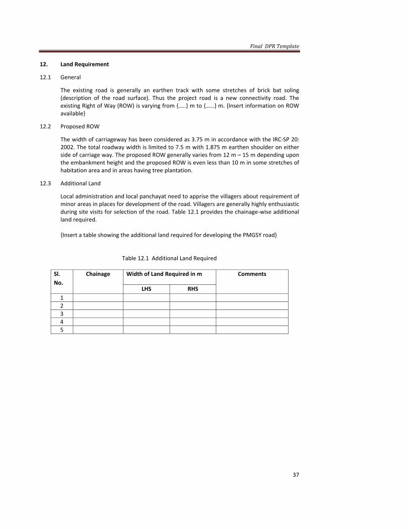
Local administration and local panchayat need to apprise the villagers about requirement of minor areas in places for development of the road. Villagers are generally highly enthusiastic during site visits for selection of the road. Table 12.1 provides the chainage‐wise additional land required.
{Insert a table showing the additional land required for developing the PMGSY road}
Table 12.1 Additional Land Required
Width of Land Required in m Sl. No.
Chainage
LHS RHS
Comments
1 2 3 4 5

Final DPR Template
38
13. Utility shifting/relocation 13.1 Existing utilities
{Insert list of existing utilities that require relocation along the project road with chainage details in a tabular form. This should connect to the decisions taken during transect walk. The existing utilities must be shown on the drawings. Utilities to be relocated must be highlighted and the new location shown on the drawings}
13.2 {Insert list of departments responsible for utility shifting}
13.3 {Insert rules pertaining to shifting of utilities}
13.4 An estimate for relocation of utilities is given below in Table 13.1
{Provide an estimate with breakdown of costs for relocation of utilities}
Table 13.1 Estimated Cost for Relocation of Utilities
Sl. No. Utility Type Qty Estimated Rate
Estimated Cost
1 {For example, power poles}
2
3
Etc.
Estimated Total Cost
Final DPR Template
39
14. Traffic Management and Road Safety Measures
{This DPR may be subjected to a road safety audit by an independent third party. The recommendations of the road safety audit as approved by PIU shall be incorporated in the final DPR.}
14.1 Road Furniture
{"Read and delete: Delete write‐up on road furniture that have not been provided.} Road Furniture details include:
Road markings Cautionary, mandatory and information signs KM stones and 200m stones Delineators and object markers Guard posts, crash barriers and speed breakers Median & footpath barriers
14.1.1 Road Markings
Road markings perform the important function of guiding and controlling traffic on a highway. The markings serve as psychological barriers and signify the delineation of traffic paths and their lateral clearance from traffic hazards for safe movement of traffic. Road markings are therefore essential to ensure smooth and orderly flow of traffic and to promote road safety. The Code of Practice for Road Markings, IRC: 35‐1997 has been used in the study as the design basis. Schedules of Road Markings are included in contract drawings.
14.1.2 Cautionary, Mandatory and Informatory Signs
Cautionary, mandatory and informatory signs are provided depending on the situation and function they perform in accordance with the IRC: 67‐2001 guidelines for Road Signs.
Overhead signs are proposed in accordance with IRC: 67‐2001.
14.1.3 Kilometer Stone and Hectometer Stone
The details of kilometre stones are in accordance with IRC: 8‐1980 guidelines. Both ordinary and fifth kilometre stones are provided as per the schedule. Kilometre stones are located on both the side of the road.
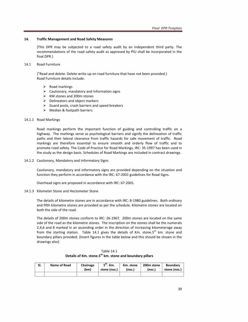
The details of 200m stones conform to IRC: 26‐1967. 200m stones are located on the same side of the road as the kilometre stones. The inscription on the stones shall be the numerals 2,4,6 and 8 marked in an ascending order in the direction of increasing kilometerage away from the starting station. Table 14.1 gives the details of Km. stone.5th km. stone and boundary pillars provided. {Insert figures in the table below and this should be shown in the drawings also}
Table 14.1
Details of Km. stone.5th km. stone and boundary pillars
Sl. Name of Road Chainage (km)
5th. Km. stone (nos.)
Km. stone (nos.)
200m stone (nos.)
Boundary stone (nos.)

Final DPR Template
40
14.1.4 Delineators and Object Markers
Roadway delineators are intended to mark the edges of the roadway to guide drivers on the alignment ahead. Object markers are used to indicate hazards and obstructions within the vehicle flow path, for example, channelising islands close to the intersections.
Delineators and object markers are provided in accordance with the provisions of IRC: 79‐1981. They are driving aids and should not be regarded as substitutes for warning signs, road markings or barriers.
14.1.5 Guard Posts, Crash Barriers and Speed Breakers
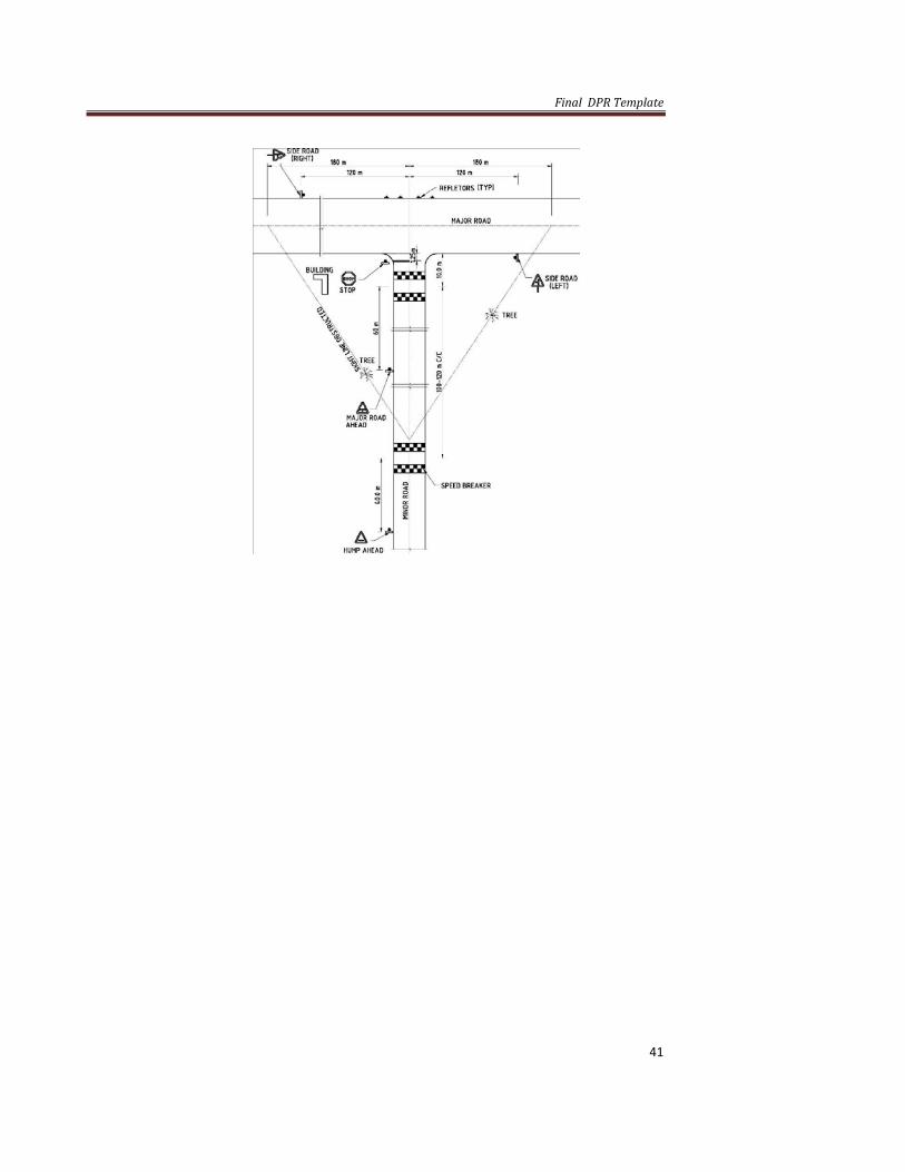
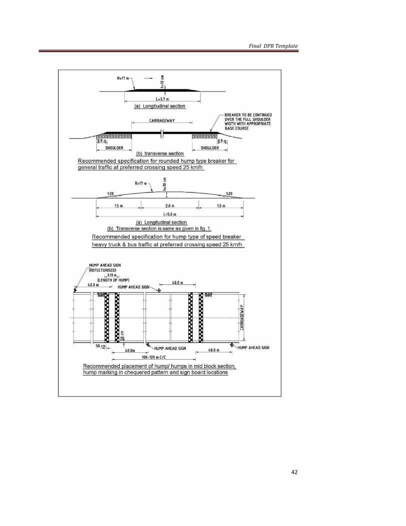
Guard posts are proposed on embankments of height more than 1.5m and bridge approaches. The spacing of guard post shall be 10.0 m c/c in these areas. Typical Guard post consists of pre‐cast (M20) CC post of size 200 mm x 200 mm and a height of 600 mm above ground level. They are encased in M15 cement concrete to a depth of 450 mm below ground level. Guard posts are painted with alternate black and white reflective paint of 150 mm wide bands. Table 14.2 gives the details of guard posts, crash barrier and speed breakers. A layout of a typical speed breaker is given below. {Insert figures in the table below and this should be shown in the drawings also}
Table 14.2 Details of guard posts, crash barrier and speed breakers
Sl. Chainage
(km) Guard post
(nos.) Crash Barrier
(m) Speed breakers (nos)
14.2 Temporary traffic control
The road under consideration has to be widened alongwith the bridges and culvert. The list below provides the c/d structures to be widened/reconstructed and temporary traffic control measures to be implemented. Table 14.3 gives the section‐wise details of temporary traffic control measures to be adopted.
{Insert table showing section/chainages where temporary traffic control measures will be required and type of control like diversion etc.}
Table 14.3 Details of temporary traffic control measures to be adopted
Sl. Chainage
(km) Temporary traffic control measures to be adopted
Final DPR Template
41
Final DPR Template
42
Final DPR Template
43
14.3 Checklist for Road Safety Measures
{Insert description of road safety issues identified during design and provide details of mitigation measures adopted. Examples of mitigation measures that may be required are:
Sl Road Safety Checklist a A minimum 100 mm thickness of pavement GSB layer constructed to the full roadway
width.(Insert Justification for the same) b The upper layer of all shoulders of sub‐base quality compacted to a minimum thickness if 100
mm. c Shoulder side slopes are not be steeper than 2H:1V unless stone pitching of the slope is
provided. d Speed breakers as per NRRDA circular comply with the requirements of IRC:99‐1988 for general
traffic. e Speed breakers placed at the threshold of a habitation and at regular intervals (150 ‐200 m)
through the habitation. f Within densely populated habitations, a cement concrete (CC) pavement or V‐shaped side
drain is constructed to the full width of the available roadway. g Within habitations, wherever deep side drains are constructed either within or adjacent to the
roadway, is covered by slabs laid level with the adjacent pavement and capable of being manually removed.
h In habitations where child playing areas border the road, a low profile wall, raised kerb or similar form of boundary marking (depending on the site conditions), is constructed to create a physical boundary and act as a deterrent to the random movement of a child onto the road.
i On roads where, because of the lack of dry land in the general area, the shoulder will be continually occupied and only intermittently available for traffic, speed breakers are installed at regular intervals, not more than 300 m apart, for the entire length of the road.
j The drawings show all obstructions in the proposed road shoulder with a note that the obstruction is to be removed.
k If a shoulder obstruction cannot be removed, hazard markers are installed to mark the Obstruction
l Hazard markers are installed at all pipe culvert headwalls. m Hazard markers are installed at each end of all box culverts, river crossing causeways and
similar CD structures. n Hazard markers are installed at any discontinuity in the shoulder. o Directional sight boards are installed on all sharp curves and bends. p Speed breakers are provided at sharp curves and bends where the curve design speed is less
than 40 km/h in plain and rolling terrain, and less than 25 km/h in mountainous and steep terrain.
q Speed breakers are provided and directional sight boards installed at sites where reverse horizontal curves are closely spaced and speed reduction is required.
r At a main road intersection, signs and pavement markings for STOP control on the PMGSY village road are installed, side road warning signs on the main road and intersection warning signs on the village road are installed, and speed breakers on the PMGSY village road are provided as given in the figures (refer IRC 99‐1988).
This DPR may be subjected to a road safety audit by an independent third party. The recommendations of the road safety audit as approved by PIU shall be incorporated in the final DPR.}
Road safety issues identified during the design were and the mitigation measures are included in all designs and shown on the DPR drawings. Details of the issues and measures are: {Insert details in tabular format on chainage wise basis.}

Final DPR Template
44
Table 14.4
Details of Road Safety issues and mitigation measures to be adopted
Sl.No. Chainage Safety issues Mitigation measures adopted
Remarks
Final DPR Template
45
15. Specification
15.1 General
The “Specification for Rural Roads” published by IRC on behalf of the Ministry of Rural Development, Govt. of India has been followed.
15.2 Construction Equipment
Construction by manual means and simple tools has been considered for the project as per the guideline of NRRDA. For handling of bulk materials like spreading of aggregates in sub‐base & base courses by mix‐in‐place method, use of motor grader & tractor‐towed rotavator has been allowed in line with the schedule of rate for PMGSY work. Compaction of all items shall be done by ordinary smooth wheeled roller if the thickness of the compacted layer does not exceed 100 mm. It is also considered that, hot mix plant of medium type & capacity with separate dryer arrangement for aggregate shall be used for bituminous surfacing work that can be easily shifted. A self‐propelled or towed bitumen pressure sprayer shall be used for spraying the materials in narrow strips with a pressure hand sprayer. Now the vibratory rollers are also being used for rapid progress.
For structural works, concrete shall be mixed in a mechanical mixer fitted with water measuring device.
The excavation shall be done manually or mechanically using suitable medium size excavators.
15.3 Construction Methods
15.3.1 Preparation for Earthwork
After setting out existing ground shall be scarified to a minimum depth of 150 mm and leveled manually and compacted with ordinary roller to receive the first layer of earthwork. In filling area, existing embankment will be generally widened on both sides as per the alignment plan. Continuous horizontal bench, each at least 300 mm wide, shall be cut on the existing slopes for bonding with the fresh embankment/ subgrade material as per Cl 301.7.
15.3.2 Embankment work
Material from borrow pits will be used for embankment construction as well as the approved material deposited at site from roadway cutting and excavation of drain & foundation may be used. Layer of the earth shall be laid in not more than 25 cm (loose) thick layers & compacted each layer of the soil up to 30 cm below the subgrade level at OMC to meet 97% of Standard Proctor Density.
Material for embankment and sub‐grade shall satisfy the requirements of Table 300‐1 and 300‐2 as per the Specification for Rural Roads.
15.3.3 Sub‐grade
Material from borrow pits will be used for construction of top 30 cm as sub‐grade. Soil in these sections is quite good for road construction. Top 30 cm upto the subgrade level and shoulder at OMC to meet 100 % of Standard Proctor Density by proper control of moisture and by required compaction with a smooth wheeled roller.
Final DPR Template
46
15.3.4 Sub‐base
Sub base material in the form of stone aggregates and sand as available in the area to be used in GSB Grade II layer.
15.3.5 Base
Stone aggregates will be used in base course. 63 mm to 45 mm size (Grading 2) aggregate has been proposed for the bottom layer and 53 mm to 22.4 mm (Grading 3) size has been proposed for the top layer.
15.3.6 Shoulder
Earthen shoulder shall be constructed in layers and compacted to 100% of Proctor’s Density. First layer of shoulder shall be laid after the sub–base layer is laid. Thereafter earth layer shall be laid with base layer of pavement and compacted.
15.3.7 Surfacing
Slow setting bitumen emulsion will be applied as primer on Water Bound Macadam (WBM) layer. Emulsion shall be sprayed on surface with pressure distributor. Rapid setting bituminous emulsion shall be used for Tack coat.
Premixed carpet and mixed with equivalent viscosity grade bitumen shall be laid as surfacing course. 6 mm thick Type B seal coat is considered for sealing of the premixed carpet.
15.3.8 Structural Works
Following grades of concrete are proposed for Structural works and comply with MORD and IRC specifications:
• Concrete in superstructure of slab culvert – M‐{Insert grade} (RCC) • Concrete in abutment cap, dirt wall of slab culverts – M‐{Insert grade} (RCC) • Brickwork in abutment, return wall, headwall ‐ M‐{Insert grade} (RCC) • Concrete below abutment, return wall, headwall – M‐{Insert grade} (RCC)
{Insert any other new specification adopted like hard shoulders and rigid pavement.}

Final DPR Template
47
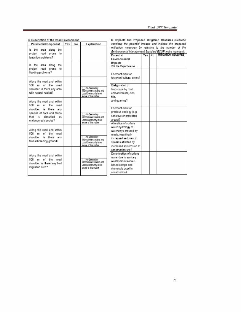
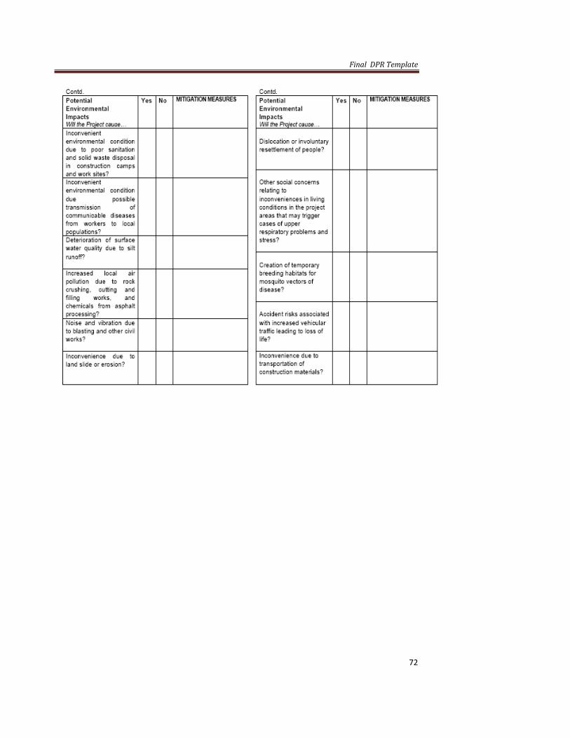
10. Environmental Issues
16.1 Alignment
The proposed road has planned to be designed considering the impact on environment. Proposed road alignment follows existing pathway to the maximum extent so that huge land acquisition is not necessary for construction of the project road. Proposed road, when completed, will be an addition to the aesthetics of this rural area.
16.2 Environmental Sensitive Area (National Park, Wild Life Sanctuary, Protected /Reserve Forest,
Wet land etc.)
The alignment will be finalised avoiding the environmental sensitive areas such as National Park, Wild Life Sanctuary, Protected /Reserve Forest, Wet land etc. It is also necessary to maintain the minimum distance of 500 m of the project road from environmental sensitive area.
16.3 Construction Camp
Construction camps will be established away from forest area/water body. The minimum facilities such as water supply, sanitation, storm water drainage, solid waste management and first aid box will be provided during the construction period of the project. Necessary provision for rehabilitation or restoration after the completion of construction phase will be done.
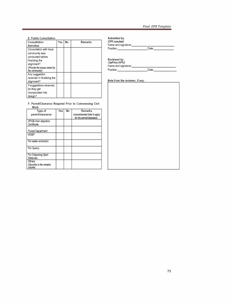
16.4 Permit / Clearance required prior to commending of civil work
• No objection Certificate‐ This will be taken by PIU from SPCB (State Pollution Control
Board).
• Forest Department‐ If the project road passing thorough forest land and acquisition of the same is involved and it will be taken by PIU from Forest Department
• Consent to establish (CFE) and Consent to Operate (CFO) ‐ This is required for Plant Hot Mix Plant, WMM Plant, Batching Plant required for the project and the same will be taken by the Contractor from SPCB.
• Lease from Mines & Geology‐ This will be taken by the Contractor for new Stone Quarry required for the project.
16.5 Borrow area
The filling soil will have to be procured from borrow pit. Borrow area will be so excavated that the lands can reused as agricultural field. The depth of borrow pit shall not exceed 450 mm (150 mm top soil included). The top soil shall be stripped and stacked and shall be spread back on the land. As far as possible the borrow pits shall not be dug close to the road embankment. The Redevelopment of borrow area will be done before closure of the same and it will be as per agreement between landowner and the Contractor.
Final DPR Template
48
16.6 Erosion Control
Turfing of the embankment slopes and earthen shoulder to prevent erosion of slopes of the embankment, rain cuts and erosion of shoulder is being suggested.
16.7 Drainage
Suitable cross drainage structures have been provided on the basis of hydrological survey of the area. So, there will be no obstruction to the natural drainage of the area. Road side drainage is also duly considered in a manner so that surface water is led to the low points and is drained through the CD structures.
16.8 Use of Material
Cut back bitumen is not proposed in the project to avoid contamination with Kerosene. Bitumen emulsion is proposed for primer coat and tack coat.
{Insert details of actual environmental issues and their location and what treatments are proposed to mitigate them like reinstatement of borrow areas, erosion control, filling of ponds, vegetation and tree removal, forest areas, wildlife, antiquities, historic and religious sites, etc }
Final DPR Template
49
17. Analysis of Rates 17.1 General
Rates for various item of works of the project have been derived from the “Schedule of Rates {Insert year of publish} for Road works, Culvert works & Carriage etc. {Insert name of RRDA} and “Addendum & Corrigendum to Schedule of Rates” effective from {Insert date}. However in general the basic rates of material have been taken from {Insert document from which the rates were taken}. The rates of different items have been worked out inclusive of all labour charges, hire charges of Tools & Plants, Machineries and all other cost estimates for the item of work, overhead and contractor’s profit @ 12.5% and 1% cess on these.
17.2 Basic Rate of Material
The basic rates for stone materials & river bed materials have been taken from {Insert document from which the rates were taken}. For bituminous materials, basic rate at (location) for equivalent viscosity grade bitumen and for emulsion the basic rate of (location) has been considered as suggested in from {Insert document from which the rates were taken}. Basic rate of other materials like coarse & fine sand, cement are as per the latest from {Insert document from which the rates were taken}. Basic rate of steel materials at sub‐divisional office has been considered in analysis after adding cost of carriage, loading & unloading.
17.3 Lead for Materials
For stone aggregates and sand, lead from source to work site is calculated from the district map and block level map of core network and finalizing the same in discussion with PIU. The supply of different materials to worksite is by road. Lead for bituminous & steel materials are similarly obtained using SOR. {Insert the analysis of rates for which rates are not provided in the SOR}.
Final DPR Template
50
18. Cost Estimate
18.1 General
Cost Estimate of project has been arrived on the following basis
• Selection of Items of work • Estimation of item wise quantities • Analysis of Rates
18.2 Estimation of Quantities
All the relevant road and structure work Items will be identified as per survey, design and drawings. Following major item of works considered are given below:
• Site clearance, dismantling and earthwork • Pavement works (GSB, WBM, Bituminous layers) • Cross drainage structure works • Drainage and protective works • Utility relocation • Road safety and furniture • Maintenance works
Quantity of earthwork will be derived from the proposed cross section drawings. Volume of cut and fill will be obtained directly using the design package software. Quantity derived from software will be manually verified. There are same stretches of the road in cut section. The details are provided chainage wise in Table‐18.1 of total cut and fill volume. The soil obtained from roadway excavation shall be used for construction of embankment and shall be paid as per item no.4. All other quantities will be computed from the drawings of finished road, miscellaneous drawings & drawings of CD Structures.
{Insert Table of cut and fill volume in Annexure 3}
18.3 Abstract of Cost
Unit rates will be derived by using the “Schedule of Rates for Road Works, Culvert works and Carriage etc. {Insert name of SRRDA}”. The abstract of Cost estimate is given in the Table below.
{Insert the details of cost in Format F6 & Format F7}.
18.4 Maintenance
Cost of Annual Maintenance for five years after completion of project will be estimated as per the PMGSY Guidelines. Different activities of ordinary repairs are done as and when.
{Insert total Cost of 5 year Routine Maintenance Works in Format F6}.
Final DPR Template
51
19. Construction Program
19.1 General
Assuming that the Construction of the Batch – {Insert Batch No.} roads will start from {Insert possible construction date.} This is a high rainfall area and rainy season extends from April to September. However, the construction program is based for a total working period of 12 months, considering the program set out by MoRD. Generally, dry working season of about 8 months are required for construction of PMGSY roads. However, works will be affected for the monsoon during the month June to September.
It is anticipated that some activity like collection of materials, CD works etc. will continue in monsoon period also.
19.2 Realistic duration
{Insert a reasonably realistic duration of the contract}
{Insert Bar Chart/ Network showing the different construction activities in months/weeks}
Final DPR Template
52
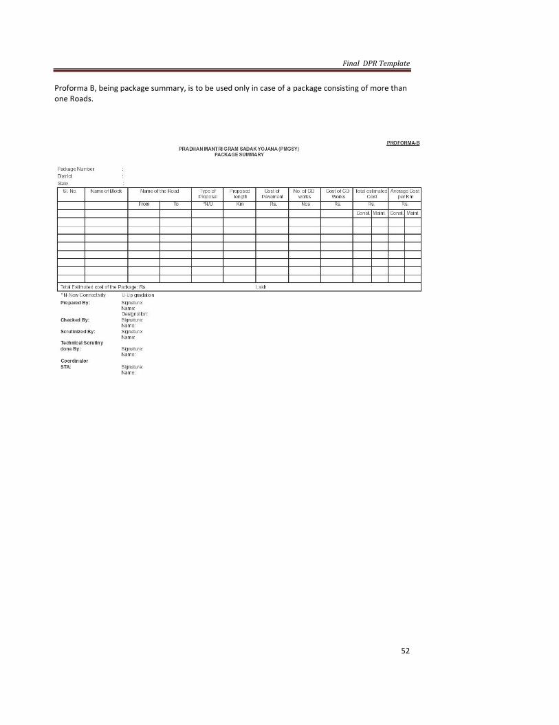
Proforma B, being package summary, is to be used only in case of a package consisting of more than one Roads.

Final DPR Template
53
Final DPR Template
54
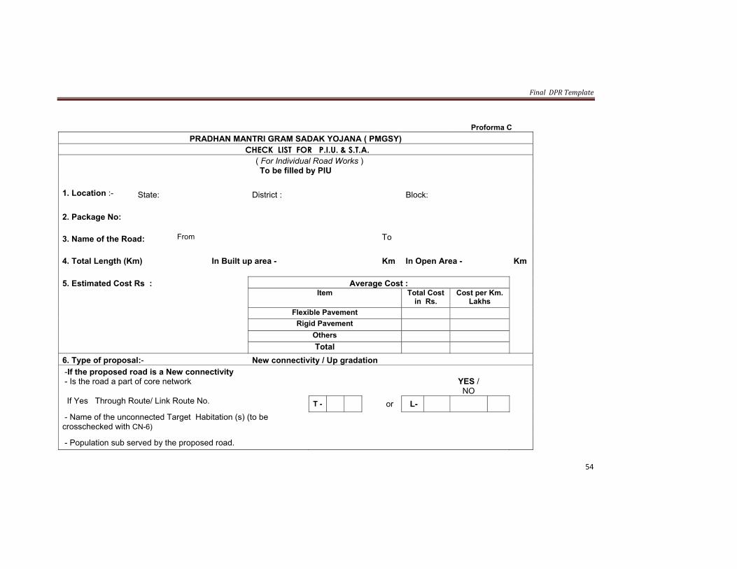
Proforma C
PRADHAN MANTRI GRAM SADAK YOJANA ( PMGSY) CHECK LIST FOR P.I.U. & S.T.A.
( For Individual Road Works ) To be filled by PIU
1. Location :- State: District : Block: 2. Package No: 3. Name of the Road: From To 4. Total Length (Km) In Built up area - Km In Open Area - Km 5. Estimated Cost Rs : Average Cost :
Item Total Cost
in Rs. Cost per Km.
Lakhs Flexible Pavement Rigid Pavement Others Total 6. Type of proposal:- New connectivity / Up gradation -If the proposed road is a New connectivity - Is the road a part of core network
YES / NO
If Yes Through Route/ Link Route No. T - or L- - Name of the unconnected Target Habitation (s) (to be
crosschecked with CN-6) - Population sub served by the proposed road.
Final DPR Template
55
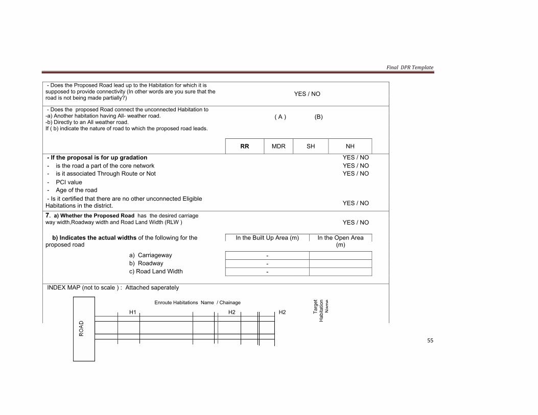
- Does the Proposed Road lead up to the Habitation for which it is supposed to provide connectivity (In other words are you sure that the road is not being made partially?)
YES / NO
( A ) (B)
- Does the proposed Road connect the unconnected Habitation to -a) Another habitation having All- weather road. -b) Directly to an All weather road. If ( b) indicate the nature of road to which the proposed road leads.
RR MDR SH NH
- If the proposal is for up gradation YES / NO - is the road a part of the core network YES / NO - is it associated Through Route or Not YES / NO - PCI value - Age of the road
- Is it certified that there are no other unconnected Eligible Habitations in the district. YES / NO
7. a) Whether the Proposed Road has the desired carriage
way width,Roadway width and Road Land Width (RLW ) YES / NO
b) Indicates the actual widths of the following for the proposed road
In the Built Up Area (m) In the Open Area (m)
a) Carriageway - b) Roadway -
c) Road Land Width - INDEX MAP (not to scale ) : Attached saperately Enroute Habitations Name / Chainage H1 H2 H2
MD
R-4
2
Targ
etH
abita
tion
Nam
e

Final DPR Template
56
CD1 CD2 CD3
Name of Road : Cross Section details a) Cross Section of The Existing road showing different component layers. b) Cross Section of The Proposed road showing different component layers
(Should be as per Actual Provisions of DPR)

Final DPR Template
57
8. Base year traffic volume Month & Year of Traffic Volume Count = Motorised Traffic Non Motorised Traffic
Trucks Agricultural Tractors Trallers
Buses Animal Drawn Vechicle
Days Cars,Jeep, Vans,Three Wheelers
Motorised two
Wheelers
Light Commercial
Vehicle
L U OL L U OL L U OL
Cycles Cycle Rickshawa
SWC Num. Tyred
Day 1
Day 2
Day 3
Average
ADT in the year of Traffic Count = Growth rate adopted (%) = Base Year Traffic AADT (T) =
Design Life = Years Number of Harvesting Seasons = No. of Days in Each Harvesting Season (t) = Value of (n) assumed = Cumulative ESAL = Traffic Category = 9 Subgrade CBR ( for Different Sections ) = Chainage CBR % 10. Cost Details Cost Rs. Cost /km
(Rs) A. General Costs Cost of Preparation of DPR B. Pavement Components
Description of layer Thickness in mm
Quantity Cost Rs. Cost/ km (Rs)
Final DPR Template
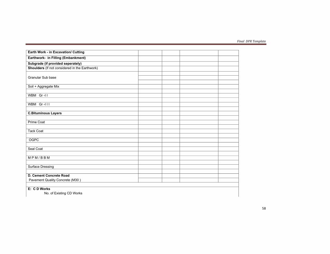
58
Earth Work - in Excavation/ Cutting Earthwork- in Filling (Embankment) Subgrade (if provided seperately) Shoulders (If not considered in the Earthwork) Granular Sub base Soil + Aggregate Mix WBM Gr -I I WBM Gr -I I I C.Bituminous Layers Prime Coat Tack Coat OGPC Seal Coat M P M / B B M Surface Dressing D. Cement Concrete Road Pavement Quality Concrete (M30 ) E: C D Works No. of Existing CD Works
Final DPR Template
59
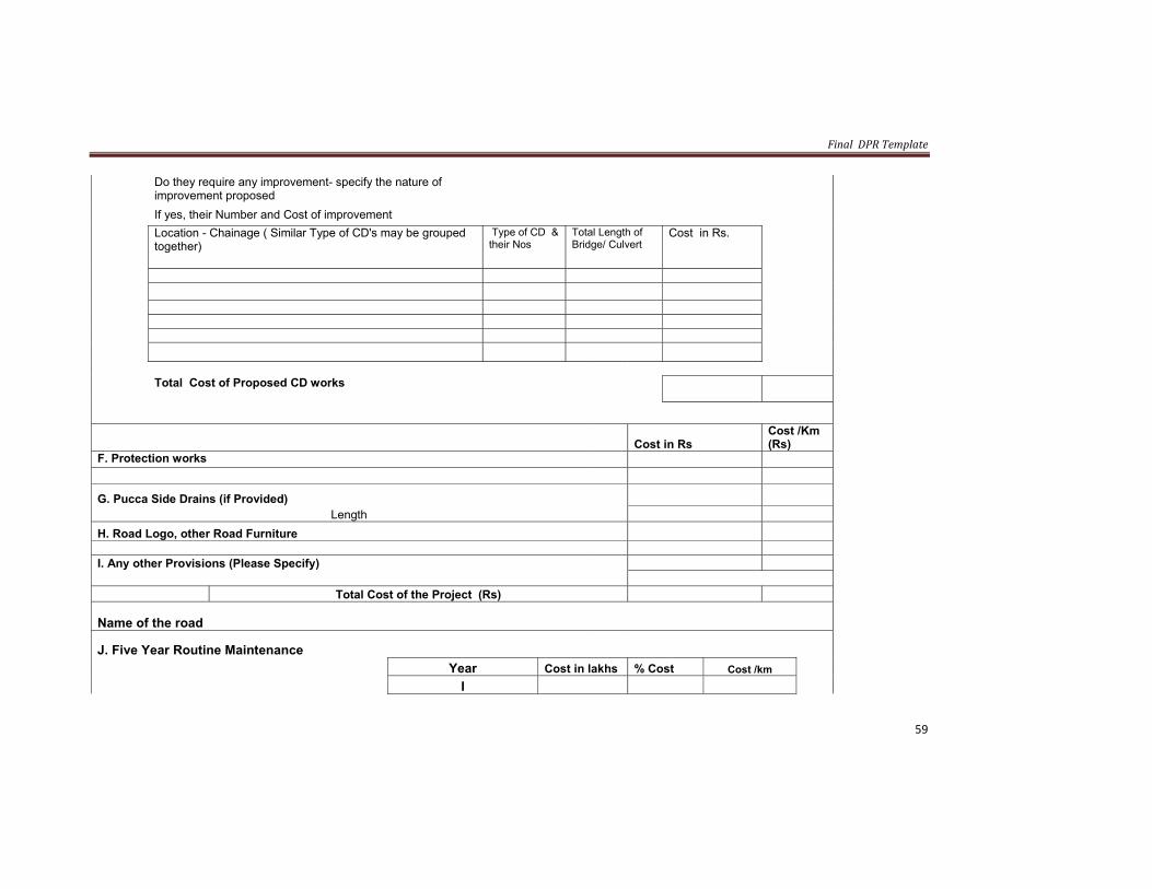
Do they require any improvement- specify the nature of improvement proposed
If yes, their Number and Cost of improvement Location - Chainage ( Similar Type of CD's may be grouped
together) Type of CD & their Nos
Total Length of Bridge/ Culvert
Cost in Rs.
Total Cost of Proposed CD works
Cost in Rs
Cost /Km (Rs)
F. Protection works
G. Pucca Side Drains (if Provided) Length H. Road Logo, other Road Furniture I. Any other Provisions (Please Specify) Total Cost of the Project (Rs)
Name of the road
J. Five Year Routine Maintenance Year Cost in lakhs % Cost Cost /km I

Final DPR Template
60
II III IV V Total Maintenance Cost 11. Whether the road has Geometrics as per Rural Roads Mannual RRM / Latest Circulars of NRRDA. 12.Whether C.D.works / Protection works are provided as per RRM / Latest Circulars of NRRDA/ Respective Codes. 13. Whether the Cost etimates are as per standerd data analysis and S.S.R.
14. Sources and the Lead distances of Materials are as under
Material Source Lead Distance
(Km)
Material Source Lead Distance
Earth Cement Murrum (Subgrade) Emulsion Aggregate Bitumen Sand Steel Certified that information provided is true Prepared By (Name)
Checked By
Scrutinized By
Counter Signatures of
Final DPR Template
61
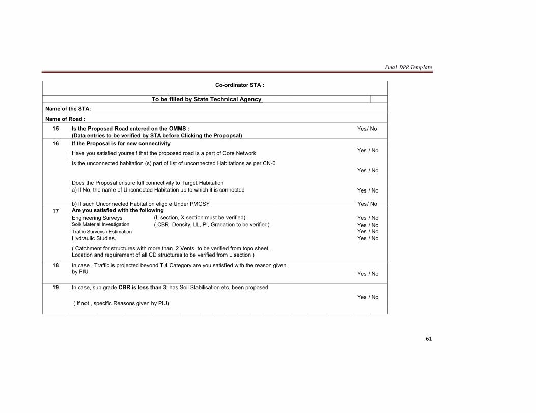
Co-ordinator STA :
To be filled by State Technical Agency
Name of the STA:
Name of Road : 15 Is the Proposed Road entered on the OMMS : Yes/ No
(Data entries to be verified by STA before Clicking the Propopsal) 16 If the Proposal is for new connectivity Yes / No Have you satisfied yourself that the proposed road is a part of Core Network
Is the unconnected habitation (s) part of list of unconnected Habitations as per CN-6
Yes / No Does the Proposal ensure full connectivity to Target Habitation a) If No, the name of Unconected Habitation up to which it is connected Yes / No b) If such Unconnected Habitation eligble Under PMGSY Yes/ No
17 Are you satisfied with the following Engineering Surveys (L section, X section must be verified) Yes / No Soil/ Material Investigation ( CBR, Density, LL, PI, Gradation to be verified) Yes / No Traffic Surveys / Estimation Yes / No Hydraulic Studies. Yes / No
( Catchment for structures with more than 2 Vents to be verified from topo sheet. Location and requirement of all CD structures to be verified from L section )
18 In case , Traffic is projected beyond T 4 Category are you satisfied with the reason given
by PIU Yes / No
19 In case, sub grade CBR is less than 3; has Soil Stabilisation etc. been proposed
Yes / No ( If not , specific Reasons given by PIU)

Final DPR Template
62
20 Is the design of the following elements as per Rural Roads Manul / Circulars of NRRDA:
Alignment & Geometrics Yes / No Location and type of CD works and Yes / No Side drains Yes / No Integration for Cross and longitudinal Drainage Yes / No Protection Works Yes / No
21 Is the design of flexible Pavement as per IRC SP: 72- 2007 and design of Rigid Pavement as per IRC SP:62- 2004 . Yes / No
22 Yes / No
Does the Estimation Conform to Standard Rate Analysis and SSR generated for the current Phase
23 Does the proposal have provisions for PMGSY Logo Sign Boards and Information Board Km/Hm Stones Yes / No Guard Stones (where necessary ) Yes / No Traffic Sign Boards (as necessary) Yes / No
24 Secific Remarks, if any, by STA
( Specific remarks of STA about the overall project are necessary on each DPR)
Certified that the Design and Estimation for the Proposed Road work are based on the data and SSR provided by PIU Engineers . The Proposal after final Correction is entered on the OMMS.The Propasal may be considered for clearance.

Final DPR Template
63
Technical Scrutiny at STA done by: Signature Co-ordinator STA: Name Signature Date Name Date
Final DPR Template
64
Final DPR Template
65
Final DPR Template
66

Final DPR Template
67
Final DPR Template
68
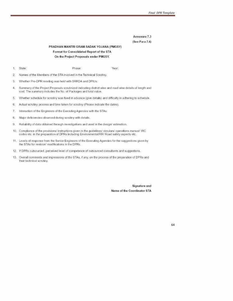
FORMATF.9A
PRADHAN MANTRI GRAM SADAK YOJANA (PMGSY)
CERTIFICATE OF GROUND VERIFICATION FROM EXECUTIVE ENGINEER! HEAD PIU 1 a) Certified that the Land width for the Road is available and that no additional land is required; or
b) Certified that land width for the Road is likely to be available as certified by the Panchayats.
2 a) Certified that no forest land is involved along the entire road way; or
b) Certified that the case for permission under Forest conservation Act has been moved to the Forest Department on (Date) and file or case no.
3 Certified that the DPR has been checked at site by
AE
EE
SE
On date
Executive Engineer,
Head of PIU.
Final DPR Template
69
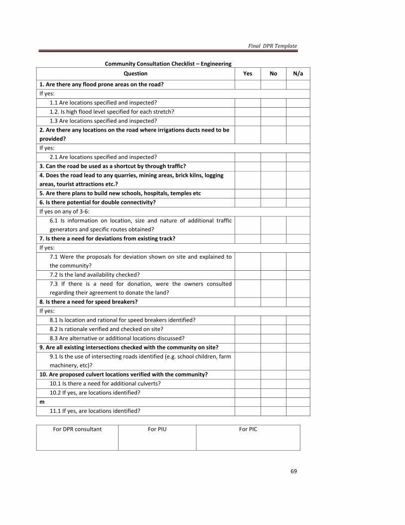
Community Consultation Checklist – Engineering
Question Yes No N/a
1. Are there any flood prone areas on the road?
If yes:
1.1 Are locations specified and inspected?
1.2. Is high flood level specified for each stretch?
1.3 Are locations specified and inspected?
2. Are there any locations on the road where irrigations ducts need to be provided?
If yes:
2.1 Are locations specified and inspected?
3. Can the road be used as a shortcut by through traffic?
4. Does the road lead to any quarries, mining areas, brick kilns, logging areas, tourist attractions etc.?
5. Are there plans to build new schools, hospitals, temples etc
6. Is there potential for double connectivity?
If yes on any of 3‐6:
6.1 Is information on location, size and nature of additional traffic generators and specific routes obtained?
7. Is there a need for deviations from existing track?
If yes:
7.1 Were the proposals for deviation shown on site and explained to the community?
7.2 Is the land availability checked?
7.3 If there is a need for donation, were the owners consulted regarding their agreement to donate the land?
8. Is there a need for speed breakers?
If yes:
8.1 Is location and rational for speed breakers identified?
8.2 Is rationale verified and checked on site?
8.3 Are alternative or additional locations discussed?
9. Are all existing intersections checked with the community on site?
9.1 Is the use of intersecting roads identified (e.g. school children, farm machinery, etc)?
10. Are proposed culvert locations verified with the community?
10.1 Is there a need for additional culverts?
10.2 If yes, are locations identified?
m
11.1 If yes, are locations identified?
For DPR consultant For PIU For PIC

Final DPR Template
70
Final DPR Template
71
Final DPR Template
72
Final DPR Template
73
Final DPR Template
74
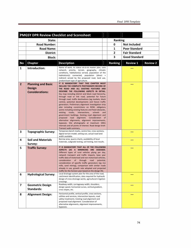
PMGSY DPR Review Checklist and Scoresheet State: Ranking
Road Number: 0 Not Included Road Name: 1 Poor Standard District: 2 Fair Standard Block: 3 Good Standard
No Chapter Description Ranking Review 1 Review 2
1 Introduction: Name of work, its status vis‐à‐vis master plan, core network, priority, terrain, geography, climatic conditions, habitation(s) served, population of the habitation(s) connected, population (direct + indirect) served by the proposed road, land use, predominant type of agriculture.
‐‐‐
2 Planning and Basic Design Considerations:
IT IS MANDATORY THAT THIS CHAPTER MUST INCLUDE THE COMPLETE PHOTOGRAPH RECORD OF THE ROAD AND ALL EXISTING FEATURES AND DESCRIBE THE FOLLOWING ASPECTS IN DETAIL. Key map including district and block road hierarchy, through road or link road, potential for future through road, traffic destinations (eg markets, block centre), potential developments and future traffic generators. Preliminary alignment investigation strip plan including constrictions on ROW, obligatory points including existing features and fixed obstacles, existing tracks, intersections, schools and government buildings. Existing road alignment and proposed road alignment. Consideration of alternative alignments, alignment improvements, bypasses. Site photographs at maximum 100m intervals and all points of interest. Road design brief. Transect walk summary.
‐‐‐
3 Topographic Survey: Temporary bench marks, centre line, cross sections, digital terrain model, setting out, actual road land width available.
‐‐‐
4 Soil and Materials Survey:
Borrow area, quarry charts, availability of local materials, subgrade testing, soil testing, test results.
‐‐‐
5 Traffic Survey: IT IS MANDATORY THAT ALL OF THE FOLLOWING ASPECTS (AS A MINIMUM) ARE ASSESSED. Different types of rural vehicles plying per day, network transport and traffic impacts, base year traffic data of motorised and non‐motorised vehicles, consideration of through road potential, consideration of specific traffic generators (eg rice mills, sand mining), comparison with similar roads already in use, growth rate adopted and projected traffic for the horizon year based on the design life.
‐‐‐
6 Hydrological Survey: Local drainage system plan for the area of the road, catchment identification, data required for hydraulic design of cross drainage works, agricultural irrigation crossings.
‐‐‐
7 Geometric Design Standards:
Roadway width, carriageway width, shoulders, design speed, horizontal curves, vertical gradient, cross slopes, etc.
‐‐‐
8 Alignment Design: Horizontal profile, vertical profile, cross sections, utilities and services, intersection layouts, road safety treatments. Existing road alignment and proposed road alignment. Consideration of alternative alignments, alignment improvements, bypasses.
‐‐‐
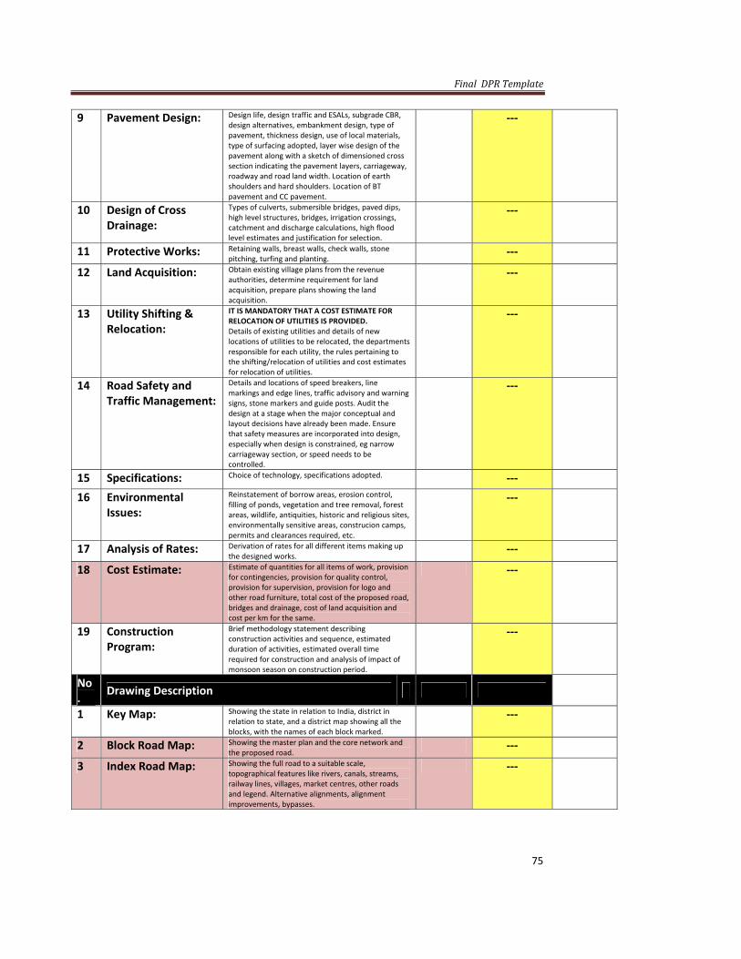
Final DPR Template
75
9 Pavement Design: Design life, design traffic and ESALs, subgrade CBR, design alternatives, embankment design, type of pavement, thickness design, use of local materials, type of surfacing adopted, layer wise design of the pavement along with a sketch of dimensioned cross section indicating the pavement layers, carriageway, roadway and road land width. Location of earth shoulders and hard shoulders. Location of BT pavement and CC pavement.
‐‐‐
10 Design of Cross Drainage:
Types of culverts, submersible bridges, paved dips, high level structures, bridges, irrigation crossings, catchment and discharge calculations, high flood level estimates and justification for selection.
‐‐‐
11 Protective Works: Retaining walls, breast walls, check walls, stone pitching, turfing and planting.
‐‐‐
12 Land Acquisition: Obtain existing village plans from the revenue authorities, determine requirement for land acquisition, prepare plans showing the land acquisition.
‐‐‐
13 Utility Shifting & Relocation:
IT IS MANDATORY THAT A COST ESTIMATE FOR RELOCATION OF UTILITIES IS PROVIDED. Details of existing utilities and details of new locations of utilities to be relocated, the departments responsible for each utility, the rules pertaining to the shifting/relocation of utilities and cost estimates for relocation of utilities.
‐‐‐
14 Road Safety and Traffic Management:
Details and locations of speed breakers, line markings and edge lines, traffic advisory and warning signs, stone markers and guide posts. Audit the design at a stage when the major conceptual and layout decisions have already been made. Ensure that safety measures are incorporated into design, especially when design is constrained, eg narrow carriageway section, or speed needs to be controlled.
‐‐‐
15 Specifications: Choice of technology, specifications adopted. ‐‐‐
16 Environmental Issues:
Reinstatement of borrow areas, erosion control, filling of ponds, vegetation and tree removal, forest areas, wildlife, antiquities, historic and religious sites, environmentally sensitive areas, construcion camps, permits and clearances required, etc.
‐‐‐
17 Analysis of Rates: Derivation of rates for all different items making up the designed works.
‐‐‐
18 Cost Estimate: Estimate of quantities for all items of work, provision for contingencies, provision for quality control, provision for supervision, provision for logo and other road furniture, total cost of the proposed road, bridges and drainage, cost of land acquisition and cost per km for the same.
‐‐‐
19 Construction Program:
Brief methodology statement describing construction activities and sequence, estimated duration of activities, estimated overall time required for construction and analysis of impact of monsoon season on construction period.
‐‐‐
No.
Drawing Description
1 Key Map: Showing the state in relation to India, district in relation to state, and a district map showing all the blocks, with the names of each block marked.
‐‐‐
2 Block Road Map: Showing the master plan and the core network and the proposed road.
‐‐‐
3 Index Road Map: Showing the full road to a suitable scale, topographical features like rivers, canals, streams, railway lines, villages, market centres, other roads and legend. Alternative alignments, alignment improvements, bypasses.
‐‐‐

Final DPR Template
76
4 Plan and Longitudinal Sections:
IT IS MANDATORY THAT ALL OF THE FOLLOWING INFORMATION (AS A MINIMUM) IS SHOWN ON THE DRAWINGS. Drawings showing 1 km in each sheet with chainage, level information, gradient details, horizontal and vertical curve details. Utilities and services, intersection layouts, road safety treatments, longitudinal drainage and drainage in built up (village) areas. Existing road alignment and proposed road alignment. Location of earth shoulders and hard shoulders. Location of BT pavement and CC pavement. Obligatory points including existing features and fixed obstacles (eg bridges, ponds, temples, etc), existing tracks, intersections, schools and government buildings. LARGE SCALE DRAWINGS WHERE ALIGNMENT DEVIATES FROM EXISTING CENTRELINE AND WHERE CLEARANCE IS TIGHT.
‐‐‐
5 Typical Cross Sections:
Drawings showing typical road cross sections, pavement details including BT and CC, hard shoulder and soft shoulder, batter slopes, longitudinal drainage. Typical cross sections in built up village areas and typical sections in normal rural areas.
‐‐‐
6 Detailed Cross Sections:
Drawings showing detailed cross sections with level information, centre line offset details and so on.
‐‐‐
7 Cross Drainage: Drawings of culverts, submersible bridges, paved dips and high level bridges, giving general arrangement drawings (GAD), structural details.
‐‐‐
8 Protective Work: Drawings of protective works like retaining walls, breast walls, check walls, drains.
‐‐‐
9 Traffic and Miscellaneous:
Drawings like kilometre stones, traffic signs, hazard signs, advisory signs, speed breakers, line marking, stone markers, guide posts, project sign boards.
‐‐‐
Reviewed By
Name: 0.0% 0 ‐‐‐
Position:
Organisation:
Date:
Total Score 0.0% ‐‐‐
Instructions and Notes
1 Complete the road details in the title block and the reviewer details in the Reviewed By block.
2 Review DPR Report chapter by chapter. Rank each as not included (0), poor standard (1), fair standard (2) or good standard (3) in the ranking cell.
3 Review Drawings section by section. Rank each as not included (0), poor standard (1), fair standard (2) or good standard (3) in the ranking cell.
4 DPR Report chapters 2, 5 and 18 and Drawing sections 2, 3, 4, 5, 6 and 7 are critical categories and have higher weighting.
5 If mandatory information is not included (Report Chapters 2 & 5 and Drawing Section 4), score is zero and DPR will not be approved.
6 Ranking less than (1), or less than (2) for critical categories, means the chapter/drawing cannot be reviewed and the DPR will not be approved.
7 The outcome for each chapter and section will be automatically displayed. If it is CHECKED (cell highlights green), the review continues.
8 All report chapters and drawing sections must achieve CHECKED status to proceed to check the overall score.

Final DPR Template
77
9 If any report chapter or drawing section does not achieve CHECKED status, the DPR will not be approved and the overall score will not be checked.
10 If the Total Score is not greater than 70%, the DPR will not be approved.
11 If the Total Score is greater than 70%, the decision will automatically be APPROVED (cell highlights green).
12 Only when all review cells give result of CHECKED and APPROVED (all review cells highlighted green) will the DPR be approved for issue.
To be assessed by PIU and score indicated Also to be assessed by STA and score indicated Also to be assessed by NRRDA and score indicated