dr-735t/e - alinco instruction manual thank you for purchasing your new alinco radio. this...
TRANSCRIPT
DR-735T/EInstruction Manual
Thank you for purchasing your new Alinco radio.
This Instruction manual contains important safety and operating instructions. Please read
this manual carefully before using the product and keep it for future reference.
VHF/UHF TWIN BAND FM RADIO

NOTICE / Compliance Information StatementThis equipment has been tested and found to comply with the limits for a Class B digital device, pursuant to part 15
of the FCC Rules.
These limits are designed to provide reasonable protection against harmful interference in a residential installation.
This equipment generates, uses, and can radiate radio frequency energy and, if not installed and used in
accordance with the instruction manual, may cause harmful interference to radio communications. However, there is
no guarantee that interference will not occur in a particular installation. If this equipment does cause harmful
interference o radio or television reception, which can be determined by turning the equipment off and on, the user
encouraged to try to correct the interference by one or more of the following measure:
Reorient or relocate the receiving antenna.
Increase the separation between the equipment and receiver.
Connect the equipment into an outlet on a circuit different from that to which the receiver is connected.
Consult the dealer or an experienced radio/TV technician for help.
Tested to Comply
With FCC Standards
FOR HOME OR OFFICE USE
Information in this document is subject to change without notice or obligation. All brand names and trademarks are
the property of their respective owners. Alinco cannot be liable for pictorial or typographical inaccuracies. Some
parts, options and/or accessories are unavailable in certain areas. Changes or modifications not modifications not
expressly approved by the party responsible for compliance could void the user’s authority to operate the
equipment.
VHF/UHF FM Radio DR-735T
This device complies with Part 15 of the FCC Rules. Operation is subject to the two conditions: (1) This device may
not cause harmful interference, and (2) this device must accept any interference received, including interference
that may cause undesired operation.
Manufacturer: ALINCO, INC
Yodoyabashi-Dai building 13th Floor 4Chome 4-9, Koraibashi, Chuo-ku, Osaka 541-0043, JAPAN
An amateur radio license is required to operate this device.
Conformity Information
In case the unit you have purchased is marked with a CE symbol, a copy of relative conformity certificate or
document can be reviewed at http://www.alinco.com/usa.html.
Information and specifications are subject to change without notice.
We will replace the manual if manufacturing/printing may be defective, but can’t be responsible of
eventual typographical errors and misinterpretations.
Alinco and ALINCO logo are registered trademarks of Alinco Incorporated in Japan,the United States,
EU States, Russia, China and many other countries.
Windows is a registered trademark of Microsoft Corporation in the United States and other countries.
All other trademarks are the properties of their respective holders.
Copyright © 2016 All right reserved. No part of this document may be reproduced, copied, translated or transcribed
in any form or by any means without the prior written permission of Alinco. Inc., Osaka, Japan. English Edition
Printed in Philippines.
1
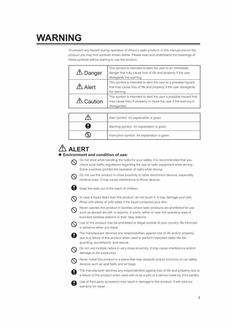
To prevent any hazard during operation of Alinco’s radio product, in this manual and on the
product you may find symbols shown below. Please read and understand the meanings of
these symbols before starting to use the product.
DangerThis symbol is intended to alert the user to an immediate
danger that may cause loss of life and property if the user
disregards the warning.
AlertThis symbol is intended to alert the user to a possible hazard
that may cause loss of life and property if the user disregards
the warning.
CautionThis symbol is intended to alert the user a possible hazard that
may cause loss of property or injure the user if the warning is
disregarded.
Alert symbol. An explanation is given.
Warning symbol. An explanation is given.
Instruction symbol. An explanation is given.
Do not drive while handling the radio for your safety. It is recommended that you
check local traffic regulations regarding the use of radio equipment while driving.
Some countries prohibit the operation of radio while driving.
Do not use this product in close proximity to other electronics devices, especially
medical ones. It may cause interference to those devices.
Keep the radio out of the reach of children.
In case a liquid leaks from the product, do not touch it. It may damage your skin.
Rinse with plenty of cold water if the liquid contacted your skin.
Never operate this product in facilities where radio products are prohibited for use
such as aboard aircraft, in airports, in ports, within or near the operating area of
business wireless stations or their relay stations.
Use of this product may be prohibited or illegal outside of your country. Be informed
in advance when you travel.
The manufacturer declines any responsibilities against loss of life and/or property
due to a failure of this product when used to perform important tasks like life-
guarding, surveillance, and rescue.
Do not use multiple radios in very close proximity. It may cause interference and/or
damage to the product(s).
Never install this product in a place that may obstacle proper functions of car safety
devices such as seat belts and air bags.
The manufacturer declines any responsibilities against loss of life and property due to
a failure of this product when used with or as a part of a device made by third parties.
Use of third party accessory may result in damage to this product. It will void our
warranty for repair.

2
WARNING
Be sure to reduce the audio output level to minimum before using an earphone or a
headset. Excessive audio may damage hearing.
Do not open the unit without permission or instruction from the manufacturer.
Unauthorized modification or repair may result in electric shock, fire and/or
malfunction.
Do not operate this product in a wet place such as shower room. It may result in
electric shock, fire and/or malfunction.
Do not place conductive materials, such as water or metal in close proximity to the
product. A short-circuit to the product may result in electric shock, fire and/or
malfunction.
Do not touch the heatsink (on/around the unit mostly found on mobile-base units) as it
may become very hot during/after the operation that may risk burn your skin.
Use only appropriate, reliable and certified power supply of correct voltage and
capacity.
Do not connect cables in reverse polarity. It may result in electric shock, fire and/or
malfunction.
Do not plug multiple devices including the power-supply into a single wall outlet. It
may result in overheating and/or fire.
Do not handle a power-supply with a wet hand. It may result in electric shock.
Securely plug the power-supply to the wall outlet. Insecure installation may result in
short-circuit, electronic shock and/or fire.
Do not plug the power-supply into the wall outlet if the contacts are dirty and/or dusty.
Shortcircuiting and/or overheating may result in fire, electric shock and/or damage to
the product.
Do not modify or remove fuse-assembly from the DC-cable. It may result in fire,electric
shock and/or damage to the product.
In case of the following situation(s), please turn off the product, switch off the source of
power, then remove or unplug the power-cord. Please contact your local dealer of this
product for service and assistance. Do not use the product until the trouble is resolved. Do
not try to troubleshoot the problem by yourself.
When a strange sound, smoke and or strange odor comes out of the product.
When the product is dropped or the case is broken or cracked.
When a liquid penetrated inside.
When a power-cord ( including DC-cables, AC-cables and adapters) is damaged.
For your safety, turn off then remove all related AC-lines to the product and its
accessories including the antenna if a thunderstorm is likely.
Turn off the unit, remove the mobile antenna from its base and keep it in the vehicle
if a thunderstorm is likely.
Please read cautions regarding the lightning-protection on page 4 also.
3
WARNING
Do not open the unit and its accessories. Please consult with your local dealer of this
product for service and assistance.
Do not use the product in proximity to a audio products such as TV, radio and stereo.
It may cause interference or receive interference.
Do not install in a humid, dusty or insufficiently ventilated place. It may result in
electric shock, fire and/or malfunction.
Do not install in an unstable or vibrating position. It may result in electric shock, fire
and/or malfunction when/if the product falls to the ground.
Do not install the product in proximity to a source of heat and humidity such as a
heater or a stove. Avoid placing the unit in direct sunlight.
Do not modify, dismantle, incinerate, or immerse the batteries that may be used in
accessories you use with this product.
Please check your local regulations for details on recycling option or disposal of the
batteries in your area.
Do not connect devices other than specified ones to the jacks and ports on the
product. It may result in damage to the devices.
Turn off and remove the power-source (AC cable, DC cable, battery, cigar-cable,
charger adapter etc) from the product when the product is not in use for extended
period of time or in case of maintenance.
Never pull the cord alone when you unplug AC cable from the wall outlet.
Use a clean, dry cloth to wipe off dirt and condensation from the surface of the
product. Never use thinner or benzene for cleaning. Use cleaners recommended to
audio-video devices in case very dirty.
Use only reliable power supply of specific DC output range and be mindful of the
polarity of the cables and DC jack.
Always turn off the power supply when connecting or disconnecting the cables.
When using an external antenna, make sure that the antenna ground is not common
with the ground of the power supply.
European users: When a radio is powered from an external DC power source
(adapter, power supply, cigar-plug etc), make sure that this power supply has
approval to the level of IEC/EN 60950-1.
Do not put magnetic cards like credit card, magnetic key etc. on/around the radio. It
may risk deleting data from the cards.

4
Do not remove the case or touch the interior components. Tampering can cause equipment
trouble.
Do not use or keep the radio where it is exposed to direct sunlight, dusty places, or near
sources of heat.
When transmitting for long periods of time at high power,
the radio might overheat. This product is NOT a 100%-
duty transmitter.
Turn the power off immediately if the radio emits smoke or
strange odors. Ensure the radio is safe, then bring it to the
nearest Alinco service center.
An operator’s license is required for this device.
About hazardous materials used in this product.The product that comes with this manual is free from dangerous material such as lead and
cadmium as per RoHS order of EU.
The radio has no protection against lightning.The user is responsible for providing adequate protection if he/she uses the device at home
and installs the antenna outdoor. Be aware that any outdoor antenna creates a direct path for
lighting current (more than 10kA) to the radio. This path exists whether the device is turned
ON or OFF.
Any vehicle does not present a safe environment during lightning. This environment becomes
much more dangerous if an outdoor antenna is installed on the car. Move the antenna and its
cable into the car at the first sight of forthcoming thunderstorm and lightning.
5

6

7

8
Thank you very much for purchasing this excellent Alinco radio. Our products are ranked
among the finest in the world. This radio has been manufactured with state of the art
technology and it has been tested carefully at our factory. It is designed to operate to your
satisfaction for many years under normal use.
PLEASE READ THIS MANUAL COMPLETELY TO LEARN ALL THE FUNCTIONS THE
PRODUCT OFFERS. WE MADE EVERY ATTEMPT TO WRITE THIS MANUAL TO BE AS
COMPREHENSIVE AND EASY TO UNDERSTAND AS POSSIBLE. IT IS IMPORTANT TO
NOTE THAT SOME OF THE OPERATIONS MAY BE EXPLAINED IN RELATION TO
INFORMATION IN PREVIOUS CHAPTERS. BY READING JUST ONE PART OF THE
MANUAL, YOU RISK NOT UNDERSTANDING THE COMPLETE EXPLANATION OF THE
FUNCTION.
This is an programmable key. Desired functions or operation can be assigned to key (P.63).
There is not a factory default allocation for this key, therefore only beep will be heard by
pressing this key unless this key is programmed.
Your new radio features some of the most advanced functions and reliable engineering
available anywhere. The ALINCO design philosophy is focused on developing innovative,
versatile features, including the following:
he DR-735T/E is a true dual band transceiver. Full-duplex system provides VHF/UHF
simultaneous operation, as well as VHF/VHF, UHF/UHF semi-duplex operations including
VHF Air-Band reception in AM mode.
ewly designed provides a powerful 50W both in the 144 and the 430MHz bands,
making this rig capable of long distance communication. Large heat dissipation chassis
with efficient cooling structure provides long time of operation.
-band full independence of the dial, squelch and audio level on the left and right band
with easy to press key layout.
large and clear color-selectable display panel with front control unit separation capability.
ight the RGB LED possible to set the favorite colors, including white to be registered in the
LCD backlight. Assignment of a different color for TX, RX and stand-by, as well as the
MAIN and SUB bands separately are possible.
wo PTT switches on the EMS-78 microphone with capability of programming Sub-PTT
switch for desired function such as low power TX, monitor, etc.
wo microphone connectors, one on the MAIN unit and another on the control panel for
convenient connection.
unction to support cable-clone for restoring setting or data and computer programming
capability.
quelch attenuator function.
hortcut key for easy access to set mode menu.
wo external speaker jacks to separate audio output on the left and right bands.

9
Carefully unpack to make sure the following items are found in the package in addition to this manual.
Radio Microphone EMS-78 (with dual PTT) or EMS79 (with DTMF keypad)
BAND
BAND
MAIN
SCAN MW
MWV/M
H/L V/M
MW
SETMHz
SCANMHz
VOL
MAINVOL
SQL
SQL or
(E only) (T only)
DC power cable including 15A fuse and holder
Mobile Mounting bracket
UA0038Y FM0078Z
Hardware kit for bracket
Bracket screwsAE0012(M4 x 8mm) x 4
Screws(M5 x 20mm) x 4
Hexagonal nut (M5) x 5
Tapping screws (M5 x 20mm) x 4
The standard accessories may vary slightly depending on the version you have purchased.
Please contact your local authorized Alinco dealer should you have any questions.
Standard accessories may change without notice.
Warranty PolicyPlease refer to any enclosed warranty information or contact your authorized Alinco dealer/distributor for the
warranty policy before purchase.

10
Connect the microphone plug into microphone terminal on the
right side of control panel or into other microphone terminal in
front of MAIN unit. Insert the plug until hearing a click.
IMPORTANTWhen connecting, be mindful to the modular plug direction.
Connect 50 antenna that covers 2m/70cm bands, using good quality 50 coaxial cable.
rear panel External speaker(if used)
Microphone
Antenna
IMPORTANT
Coupling the antenna to the radio via feed-lines having impedance other than 50 reduces the ef ciency of the antenna system and can cause interference to nearby televisions, radio receivers and other electronic equipment.
IMPORTANT Before connecting, be sure to turn off the radio and DC power supply. Be certain to use DC cable provided with unit.
The radio requires 13.8V DC negative grounded power supply.
Use a regulated power supply capable of providing continuous current of 12A or more.
Power supplies that do not meet specifications may cause malfunction and/or damage to the
radio and will void the warranty. Alinco offers excellent communication-grade power supplies
as optional accessories. Please contact your local authorized Alinco dealer.
VOL

11
Initial Installation
IMPORTANTDC voltage range for operating this radio is DC 11.7V to 15.8V. Radio will not operate out of this range. Inspect cable and connection regularly to be sure there is not any damage or burning.
DC power cable
DCpower supply
Black lead
Red lead
The radio may be installed in any position in your
vehicle, where the controls and microphones are
easily accessible and it does not interfere with the
safe operation of the vehicle or the performance of
the radio. If your vehicle is equipped with air bags,
be certain your radio will not interfere with their
deployment. If you are uncertain about where to mount the unit, contact your vehicle’s
manufacture.
IMPORTANT
RF Hazard WarningThe electro-magnetic (radio Frequency) exposure level of this device may exceed the European standards of the hazard level when transmitting at the high-power setting while connected to a unity gain antenna at a distance of 63cm or less from the operator. Furthermore, the hazardous RF exposure level depends on the conditions of the combination of the antenna gain, distance from the operator, output setting and installation environment, therefore the operator may be exposed to stronger RF even at a distance of more than 63cm. For safety purpose, it is recommended that the antenna be installed outside of, and as far as possible from, the operator’s area. Avoid using an excessively high-gained antenna in case the distance between the operator and the antenna is very limited. Always use the minimum necessary output power for communications.
12
Initial Installation
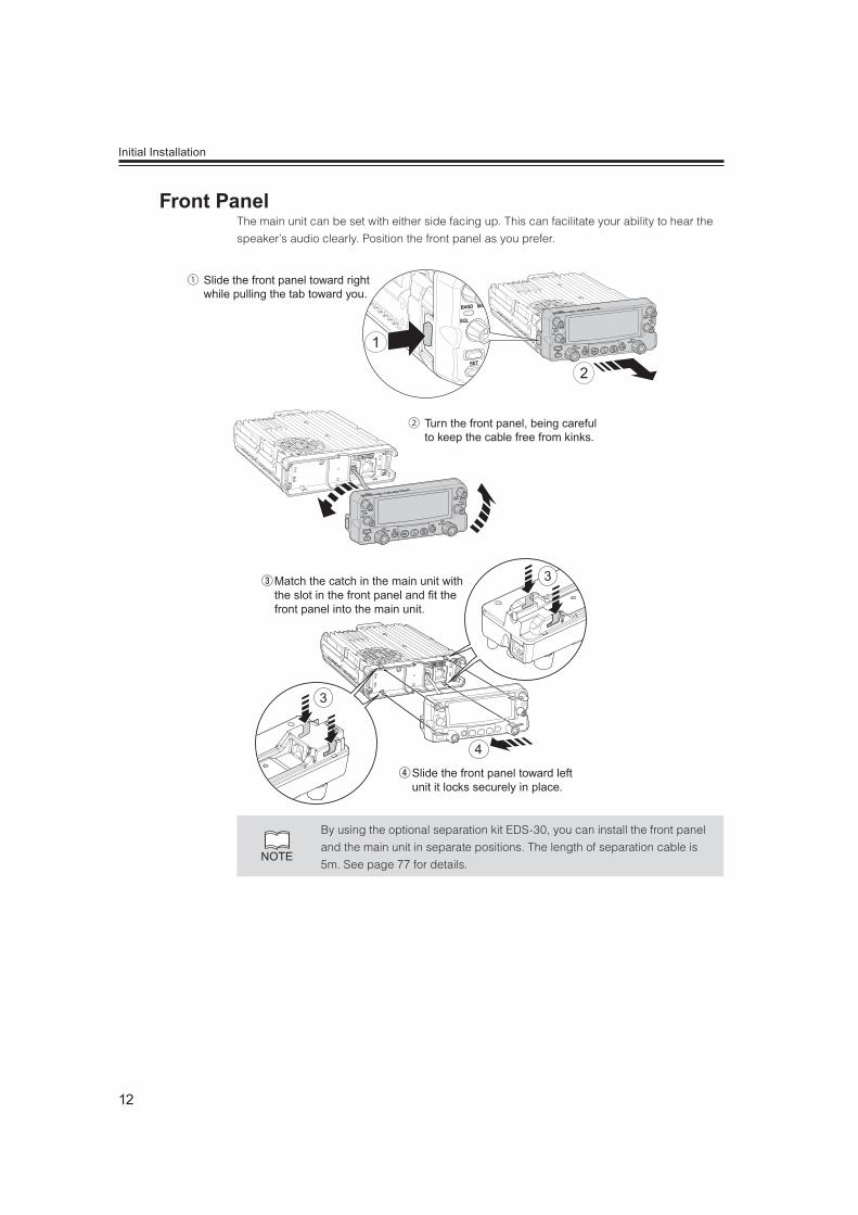
The main unit can be set with either side facing up. This can facilitate your ability to hear the
speaker’s audio clearly. Position the front panel as you prefer.
1
2
① Slide the front panel toward right while pulling the tab toward you.
② Turn the front panel, being careful to keep the cable free from kinks.
3
3
4
④ Slide the front panel toward left unit it locks securely in place.
③ Match the catch in the main unit with the slot in the front panel and fit the front panel into the main unit.
NOTE
By using the optional separation kit EDS-30, you can install the front panel
and the main unit in separate positions. The length of separation cable is
5m. See page 77 for details.
13
Initial Installation
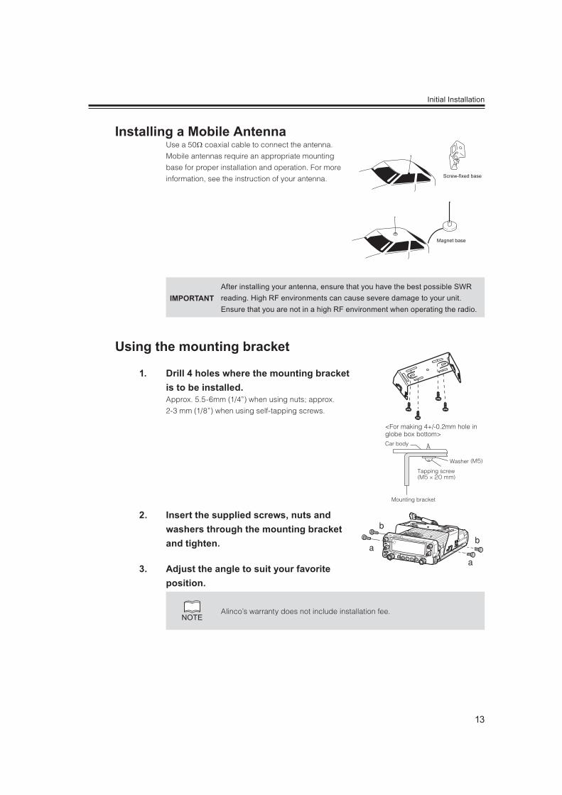
Use a 50 coaxial cable to connect the antenna.
Mobile antennas require an appropriate mounting
base for proper installation and operation. For more
information, see the instruction of your antenna.
IMPORTANTAfter installing your antenna, ensure that you have the best possible SWR reading. High RF environments can cause severe damage to your unit. Ensure that you are not in a high RF environment when operating the radio.
1. Drill 4 holes where the mounting bracket is to be installed.Approx. 5.5-6mm (1/4”) when using nuts; approx.
2-3 mm (1/8”) when using self-tapping screws.
2. Insert the supplied screws, nuts and washers through the mounting bracket and tighten.
3. Adjust the angle to suit your favorite position.
NOTEAlinco’s warranty does not include installation fee.
Magnet base
Screw-fixed base
<For making 4+/-0.2mm hole in globe box bottom>Car body
Mounting bracket
Tapping screw
Washer
VOL
14
There are 3 types of key operations; simply press, press after pressing [FUNC] key while FUNC appears on
the display, or press and hold.
Press] refers to press the key once and release the finger immediately.
FUNC + this Key] refers to press the FUNC key once, then press another key while FUNC icon appears
on the display.
Press and hold] refers to press the key and hold it. The holding time is adjustable in set mode; factory
default is 2 seconds.
Quickest way to save the change and return to operation is to press PTT key in most cases.
U
③
⑤
⑦
⑯
⑨⑫⑮⑭⑬⑪⑧
④
②
⑥
①⑩
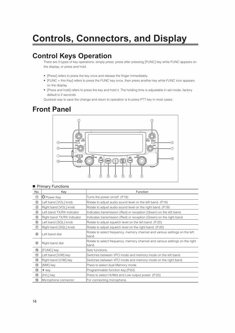
Primary FunctionsNo. Key FunctionA Power Key Turns the power on/off. (P.19)
B Left band [VOL] knob Rotate to adjust audio sound level on the left band. (P.19)
C Right band [VOL] knob Rotate to adjust audio sound level on the right band. (P.19)
D Left band TX/RX indicator Indicates transmission (Red) or reception (Green) on the left band.
E Right band TX/RX indicator Indicates transmission (Red) or reception (Green) on the right band.
F Left band [SQL] knob Rotate to adjust squelch level on the left band. (P.20)
G Right band [SQL] knob Rotate to adjust squelch level on the right band. (P.20)
H Left band dialRotate to select frequency, memory channel and various settings on the left band.
I Right band dialRotate to select frequency, memory channel and various settings on the right band.
J [FUNC] key Sets functions.
K Left band [V/M] key Switches between VFO mode and memory mode on the left band.
L Right band [V/M] key Switches between VFO mode and memory mode on the right band.
M [MW] key Press to select dual Memory mode.
N key Programmable function key.(P.63)
O [H/L] key Press to select Hi/Mid and Low output power. (P.33)
P Microphone connector For connecting microphone.
15
Controls, Connectors, and Display
Functions that requires press and holding to be activatedNo. Key FunctionB Left band [VOL] knob Switches between VHF/Air-Band and UHF on the left band (P.19)
C Right band [VOL] Knob Switches between UHF/VHF and Air-Band on the right band (P.19)
H Left band dial Switches between VFO and memory scan on the left band. (P.58)
I Right band dial Switches between VFO and memory scan on the right band. (P.58)
J [FUNC] key Sets mode. (P.34)
K Left-Band [V/M] key Switches to Call channel on the Left-Band. (P.30)
L Right-Band [V/M] key Switches to Call channel on the Right-Band. (P.30)
M [MW] key Simple Memory writing. (P.24)
O [H/L] key Key lock. (P.62)
* Hold timing is adjustable in set mode
Functions which can be activated while [FUNC] appears, after pressing [FUNC] keyNo. Key FunctionB Left band [VOL] knob Switches to the single band mode on the left band. (P.57)
C Right band [VOL] knob Switches to the single band mode on the right band. (P.57)
H Left band dial Program scan on the left band. (P.59)
I Right band dial Program scan on the right band. (P.59)
K Left band [V/M] key Write frequency to selected memory on the left band. (P.23)
L Right-Band [V/M] key Write frequency to selected memory on the right band. (P.23)
M [MW] key Sets monitor function. (Reverse function when shift activated). (P.31)
N key Selects Tone-squelch (CTCSS) or DCS. (P.65)
O [H/L] key Accesses the digital voice communication mode (required optional unit) (P.68)
Functions which can be activated while pressing the [FUNC] keyNo. Key Function
A Power key Normal Reset when turns the power on. (P.75)
B Left band [VOL] knob Selects shift or offset frequency on the left band. (P.22)
C Right band [VOL] knob Selects shift or offset frequency on the right band. (P.22)
H Left band dial Sets priority scan on the left band. (P.61)
I Right band dial Sets priority scan on the right band. (P.61)
K Left band [V/M] key Erase the memory while memory mode is selected on the left band. (P.25)
L Right band [V/M] key Erase the memory while memory mode is selected on the right band. (P.25)
M [MW] key Sets auto-dialer memory. (P.67)
N key Sets RGB backlight color. (P.63)
O [H/L] key Sets the channel name while Memory mode selected. (P.28)

16
Controls, Connectors, and Display
④ ① ②
⑥③⑤
No. Key Function
A External Speaker Jack 1 [SP1]Connects an external 8 speaker. Outputs audio of the right band. When another speaker is not connected to [SP2], left band audio is heard through internal speaker. Also [SP1] used for connecting clone or PC cables.
B External Speaker Jack 2 [SP2]Connects an external 8 speaker. Outputs audio of the left band. When another speaker is not connected to [SP1], right band audio is heard through internal speaker.
C DC Power cable Connects to the 13.8V DC power supply.
D Air-cooling fan Cools the unit during transmission or when the radio is hot.
E Antenna connector Connects to antenna with 50 impedance matched with operation frequency.
F DIN connector (6 PIN) Connects to external TNC unit for Packet communications.
Before operating, install an efficient, well-tuned antenna. The success of your installation will depend on the
type of antenna and its correct installation. Use a 50 impedance antenna and low-loss coaxial feed-line
that has a characteristic impedance of 50 .
NOTE
ransmitting without first connecting an antenna or other matched load may damage the
radio. Always connect the antenna to the radio before transmitting.
All fixed stations should be equipped with a lightning protection to reduce the risk of fire,
electric shock, and damage to the radio.
he antenna connector used is combined PL259/M. You may feel it too loose comparing
to the specific ones, but it is not a defect. Please be sure to tighten the outer ring until it
stops.
ou plan to use an external speaker, choose a speaker with an impedance of 8 . Each external speaker
jacks accept a 3.5mm (1/8") mono (2-conductor) plug.
xternal speaker adopt double port BTL, please care about the connection. Do not use the speaker that
requires grounding.
arefully insert plug into jack. Do not twist the plug and do not apply stress on speaker jacks.
hen jacks are not in use, keep the [SP] cap (speaker jack cover) closed to keep contacts clean and
avoid entering dust and other objects into the radio.
nsert plugs into jacks completely until locks to prevent damaging the jack or plug.

17
Controls, Connectors, and Display
No. Key FunctionA Appears when advanced set mode is available. (P.48)
B Appears during AM reception. (P.36)
C Appears during transmission when other band is set for mute. (P.52)
D Appears when APO function is activated. (P.49)
E Appears when setting the key lock. (P.62)
F Appears when [FUNC] key is pressed. (P.15)
G Appears when in the digital voice communication mode. (P.68)
H Appears when in packet mode. (P.55)
I Appears when cross-band repeater mode is available. (P.71)
J Appears during time out timer setting. (P.49)
K Appears during short cut setting. (P.63)
L Appears when setting the shift. (P.22)
M Appears when setting the tone squelch. (P.65)
N Appears when setting the DCS. (P.66)
O Appears when attenuator function is activated. (P.44)
P Appears when in narrow band reception mode. (P.36)
Appears when reverse mode is activated. (P.32)
Appears when Bell function is activated. (P.39)
Indicates the VHF/UHF frequency or memory name on the left band side. (P.20, 28)
Indicates the VHF/UHF frequency or memory name on the right band side. (P.20, 28)
Appears on the band with transmitting ability. (P.19)
Appears when a signal is being received. (P.31)
[S] Flashes during scan and [PS] flashes during program scan. (P.58)
Appears when transmission power is set to MID. (P.33)
Appears when transmission power is set to LOW. (P.33)
S meter Indicates received or transmitted signal level. (P.31, 32)
Appears during scan for skip channels. (P.59)
Appears when a favorite channel is selected. (P.59)
Indicates memory numbers in the memory mode. (P.23)
18
Controls, Connectors, and Display
①②
③ ⑥
④ ⑤
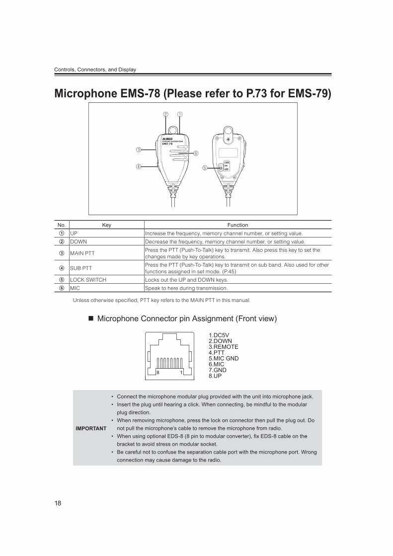
No. Key FunctionA UP Increase the frequency, memory channel number, or setting value.
B DOWN Decrease the frequency, memory channel number, or setting value.
C MAIN PTTPress the PTT (Push-To-Talk) key to transmit. Also press this key to set the changes made by key operations.
D SUB PTTPress the PTT (Push-To-Talk) key to transmit on sub band. Also used for other functions assigned in set mode. (P.45)
E LOCK SWITCH Locks out the UP and DOWN keys.
F MIC Speak to here during transmission.
Unless otherwise specified, PTT key refers to the MAIN PTT in this manual.
Microphone Connector pin Assignment (Front view)
1.DC5V2.DOWN3.REMOTE4.PTT5.MIC GND6.MIC7.GND8.UP18
IMPORTANT
Connect the microphone modular plug provided with the unit into microphone jack. Insert the plug until hearing a click. When connecting, be mindful to the modular
plug direction. When removing microphone, press the lock on connector then pull the plug out. Do
not pull the microphone’s cable to remove the microphone from radio. When using optional EDS-8 (8 pin to modular converter), x EDS-8 cable on the
bracket to avoid stress on modular socket. Be careful not to confuse the separation cable port with the microphone port. Wrong
connection may cause damage to the radio.
19
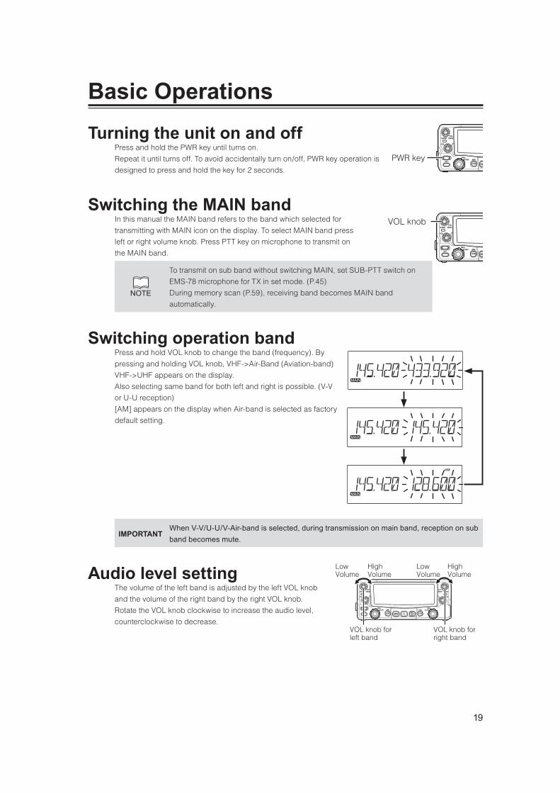
Press and hold the PWR key until turns on.
Repeat it until turns off. To avoid accidentally turn on/off, PWR key operation is
designed to press and hold the key for 2 seconds.
In this manual the MAIN band refers to the band which selected for
transmitting with MAIN icon on the display. To select MAIN band press
left or right volume knob. Press PTT key on microphone to transmit on
the MAIN band.
NOTE
To transmit on sub band without switching MAIN, set SUB-PTT switch on
EMS-78 microphone for TX in set mode. (P.45)
During memory scan (P.59), receiving band becomes MAIN band
automatically.
Press and hold VOL knob to change the band (frequency). By
pressing and holding VOL knob, VHF->Air-Band (Aviation-band)
VHF->UHF appears on the display.
Also selecting same band for both left and right is possible. (V-V
or U-U reception)
[AM] appears on the display when Air-band is selected as factory
default setting.
IMPORTANTWhen V-V/U-U/V-Air-band is selected, during transmission on main band, reception on sub band becomes mute.
The volume of the left band is adjusted by the left VOL knob
and the volume of the right band by the right VOL knob.
Rotate the VOL knob clockwise to increase the audio level,
counterclockwise to decrease.
PWR key
VOL knob
Low Volume
High Volume
Low Volume
High Volume
VOL knob for left band
VOL knob for right band

20
Basic Operations
Adjust threshold level of the squelch. A squelch eliminates the
background noise when a signal is not received.
Turn the SQL knob clockwise until white-noise (the background
noise when a signal is not received) and [BUSY] icon on the
display disappears.
The SQL should be turned fully counterclockwise when receiving weak or unstable signals. The [BUSY] icon
appears on the display while the squelch is opened (unmuted).
When you set it to a higher level, weak signals would be interrupted while monitoring or would not be
monitored at all.
Generally, you should set the squelch to the lowest level where noise would be eliminated. Depending on the
monitored frequencies and the conditions of the circumstances around you, the squelch level may need to
be adjusted.
NOTEAttenuator function is assignable to the SQL knob. (P.44)
VFO tuning is set as the default mode at the factory. VFO (variable frequency oscillator) allows you to change
the frequency in accordance with the selected channel step as you rotate the dial or by using the UP/DOWN
keys on the microphone.
VFO mode is also used to program the data to be stored in the memory channels or to change the
parameter settings of the radio.
1. Select VFO mode by pressing V/M keyPress V/M key to switch between VFO mode and
memory mode.
VFO mode : Frequency appears on the display.
Memory mode : Memory (channel) number or channel
name appears on the display.
If memories have not been programmed, the unit cannot
be switched to the memory mode.
2. Changing frequencyRotate the dial clockwise or UP key on the microphone
to increase the frequency, and counterclockwise or
DOWN key on the microphone to decrease the
frequency.
In accordance with the selected tuning step in Set
mode, frequency will be increased or decreased.
low
SQL knob for left band
SQL knob for Right band
high low high
VFO mode
Memory mode
decrease the frequency
dial
increase the frequency

21
Basic Operations
NOTE
ial and VOL are potentiometers with push-switch built in, therefore
compared to SQL, you may feel rattling on knobs but it’s not a defect.
hen using UP/DOWN keys to change the frequency, a different tone of
beep sounds to inform which direction the frequency is moving. When it
passes the 500KHz order, another beeps sounds. When the frequency
starts moving, release UP/DOWN keys to start scanning. Press PTT key
to stop. Pressing and holding them for more than 2 seconds will continue
to change the frequency as long as the UP/DOWN keys are pressed.
Changing frequency by 1 MHz stepThis will enable a quick change of frequency in 1 MHz
step:
1. Press Dial knob. The digits after 100 kHz will disappear from the display.
2. Rotate the dial clockwise or UP key on the microphone to increase the frequency, counterclockwise or DOWN key on the microphone to decrease. To return press any key or PTT key on the microphone.
Tuning steps are the minimum frequency change increments when you rotate dial or push
UP/DOWN keys on the microphone.
Factory default setting is [Auto] for left and right bands. Individual tuning steps setting is
available to all 3 bands on the left and right sides. Details of steps and frequencies in AUTO
mode are shown in Specifications at the end of this manual.
1. Press V/M key to select the VFO mode. Tuning step selection is not available when the radio is in the memory mode.
2. Press and hold a VOL knob to select the band.
3. Press and hold FUNC key until menu number 01 appears on display.
4. Rotate dial knob to select tuning step.
5. Pressing any key except PWR key or dial knob on the unit will complete the setting and the display will return to VFO mode.
Channel step setting display (default)
22
Basic Operations
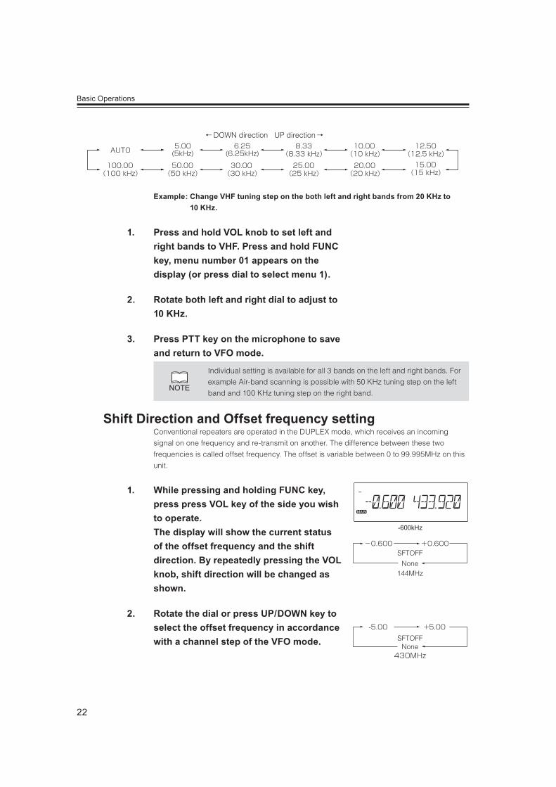
UP directionDOWN direction
AUTO 5.00(5kHz)
6.25(6.25kHz)
100.00 50.00
8.33 10.00
30.00 25.00
12.50
20.00 15.00
Example: Change VHF tuning step on the both left and right bands from 20 KHz to 10 KHz.
1. Press and hold VOL knob to set left and right bands to VHF. Press and hold FUNC key, menu number 01 appears on the display (or press dial to select menu 1).
2. Rotate both left and right dial to adjust to 10 KHz.
3. Press PTT key on the microphone to save and return to VFO mode.
NOTE
Individual setting is available for all 3 bands on the left and right bands. For
example Air-band scanning is possible with 50 KHz tuning step on the left
band and 100 KHz tuning step on the right band.
Conventional repeaters are operated in the DUPLEX mode, which receives an incoming
signal on one frequency and re-transmit on another. The difference between these two
frequencies is called offset frequency. The offset is variable between 0 to 99.995MHz on this
unit.
1. While pressing and holding FUNC key, press press VOL key of the side you wish to operate. The display will show the current status of the offset frequency and the shift direction. By repeatedly pressing the VOL knob, shift direction will be changed as shown.
2. Rotate the dial or press UP/DOWN key to select the offset frequency in accordance with a channel step of the VFO mode.
-600kHz
SFTOFF
144MHzNone
+5.00
430MHz
-5.00SFTOFF
None

23
Basic Operations
3. After pressing the dial knob, rotating the dial will change the frequency by 1Mhz depending on which direction the dial is rotated (or if the UP/DOWN keys on microphone is pressed).
4. Pressing the PTT key or any key except VOL and dial knob will complete the setting and the display will return to the original status.
NOTE
The shift setting and operation is temporary possible in the memory mode.
However, shift setting will be deleted when you change the channel, turn off
etc.
This mode allows recalling and operating the preprogrammed frequency or setting. This unit provides up to
1000 common memory channels on the left and right bands. (000 to 999CH) , 100 dual memory channels
(d00 to d99 CH), 5 pair of program-scan memory (P1A/P1b to P5A/P5b), 1 pair of VFO auto-program
memory scan, 1 CALL channel each for V and U (CALL), and 100 individual memory channels for V and U
in advanced mode (L00 to L99 / r00 to r99).
NOTE
Two type of memory channels are used in this radio.
ommon memory channels can be program and recall on both left and right bands.
ndividual memory channels are dedicated to left or right band only.
Individual memory channels provides as if operating two monoband radios’ memory
channels.
1. Select a frequency to be programmed in the VFO mode and set the parameters as appropriate. Refer to the next page for programmable parameters.
2. By Pressing FUNC key, [FUNC] and [Memory number] icons will appear on the display.
3. Rotate the dial (or press UP/DOWN keys on microphone) to select desired memory channel number.An empty channel is shown with a flashing [Memory
number] icon.

24
Basic Operations
4. By pressing V/M key while [FUNC] icon is on the display, programming will be completed and you will hear a beep sound.
IMPORTANTBe certain memory protect function in set mode is off to edit the memory channels.
One-touch programming is possible if you don’t care selecting specific memory channel
Number.
Select a frequency to be programmed in the VFO mode and set the parameters as
appropriate. Refer to the below for programmable parameters.
Press and hold MW key until a beep sounds, the current setting will be stored in an empty
memory channel of the lowest number and the number flashes 2 times.
Each memory channel including 000 to 999, d00 to d99, L00 to L99, CALL channel, APL/
APH and P A/P b channels can store following:
requency
utput power
olor setting
hift frequency
hift direction (+ / -)
one encoder frequency
one decoder frequency
one encoder / decoder setting
CS code
CS setting
arrow mode setting
M mode setting
ell setting
1. Select the memory mode by pressing V/M key.Repeat to switch between memory and VFO mode.
2. Select a memory channel.Rotating dial (or pressing UP/DOWN keys on
microphone) will increase or decrease a memory
channel number by 1 channel step.
memory channel
25
Basic Operations
NOTE
emory channels have not been programmed, the unit will not be
switched to the memory mode by pressing V/M key.
ommon memory channels will recall by pressing V/M key on the left or
right side, for Individual memory channels left V/M key will recall left
individual memory channels and right V/M key will recall right individual
memory channel.
n memory mode only programmed channels will appear on the display.
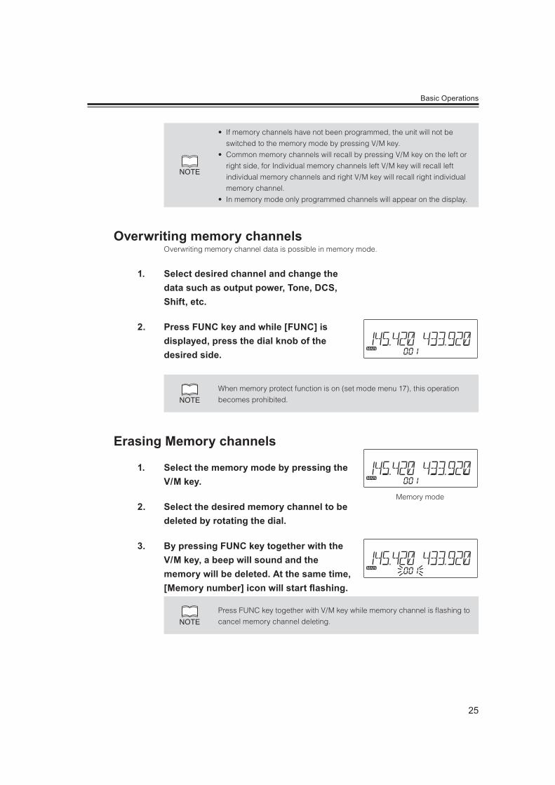
Overwriting memory channel data is possible in memory mode.
1. Select desired channel and change the data such as output power, Tone, DCS, Shift, etc.
2. Press FUNC key and while [FUNC] is displayed, press the dial knob of the desired side.
NOTEWhen memory protect function is on (set mode menu 17), this operation
becomes prohibited.
1. Select the memory mode by pressing the V/M key.
2. Select the desired memory channel to be deleted by rotating the dial.
3. By pressing FUNC key together with the V/M key, a beep will sound and the memory will be deleted. At the same time, [Memory number] icon will start ashing.
NOTEPress FUNC key together with V/M key while memory channel is flashing to
cancel memory channel deleting.
Memory mode
26
Basic Operations
1. Select memory mode and desired memory channel to copy to the VFO.
2. Press VOL knob until hearing the beep sound.
3. Press V/M key to switch to VFO mode.
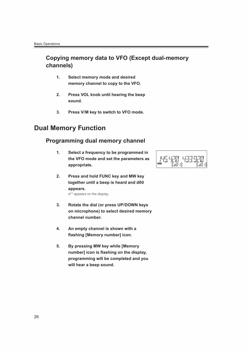
1. Select a frequency to be programmed in the VFO mode and set the parameters as appropriate.
2. Press and hold FUNC key and MW key together until a beep is heard and d00 appears.d** appears on the display.
3. Rotate the dial (or press UP/DOWN keys on microphone) to select desired memory channel number.
4. An empty channel is shown with a ashing [Memory number] icon.
5. By pressing MW key while [Memory number] icon is ashing on the display, programming will be completed and you will hear a beep sound.
27
Basic Operations
You need to program at least one dual memory channel to perform this operation.
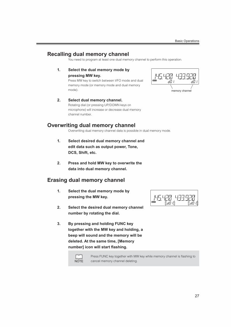
1. Select the dual memory mode by pressing MW key.Press MW key to switch between VFO mode and dual
memory mode (or memory mode and dual memory
mode).
2. Select dual memory channel.Rotating dial (or pressing UP/DOWN keys on
microphone) will increase or decrease dual memory
channel number.
Overwriting dual memory channel data is possible in dual memory mode.
1. Select desired dual memory channel and edit data such as output power, Tone, DCS, Shift, etc.
2. Press and hold MW key to overwrite the data into dual memory channel.
1. Select the dual memory mode by pressing the MW key.
2. Select the desired dual memory channel number by rotating the dial.
3. By pressing and holding FUNC key together with the MW key and holding, a beep will sound and the memory will be deleted. At the same time, [Memory number] icon will start ashing.
NOTEPress FUNC key together with MW key while memory channel is flashing to
cancel memory channel deleting.
memory channel
28
Basic Operations
The memory channel stored in the common memory, individual memory, dual memory and
program scan memory can be displayed with an alphanumeric tag instead of the default
frequency display. There are 67 characters available including A-Z, 0-9.
1. Select memory mode on the MAIN band and then select a channel to be programmed.
2. Press H/L key while pressing and holding the FUNC key.
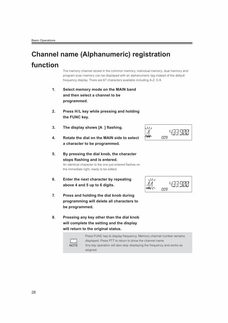
3. The display shows [A ] ashing.
4. Rotate the dial on the MAIN side to select a character to be programmed.
5. By pressing the dial knob, the character stops ashing and is entered. An identical character to the one just entered flashes on
the immediate right, ready to be edited.
6. Enter the next character by repeating above 4 and 5 up to 6 digits.
7. Press and holding the dial knob during programming will delete all characters to be programmed.
8. Pressing any key other than the dial knob will complete the setting and the display will return to the original status.
NOTE
Press FUNC key to display frequency. Memory channel number remains
displayed. Press PTT to return to show the channel name.
Any key operation will also stop displaying the frequency and works as
asigned.
29
Basic Operations
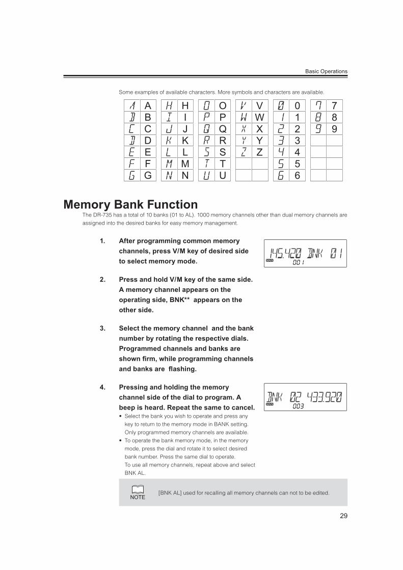
Some examples of available characters. More symbols and characters are available.
ABCDEFG
HIJKLMN
OPQRSTU
012
789
3456
VWXYZ
The DR-735 has a total of 10 banks (01 to AL). 1000 memory channels other than dual memory channels are
assigned into the desired banks for easy memory management.
1. After programming common memory channels, press V/M key of desired side to select memory mode.
2. Press and hold V/M key of the same side. A memory channel appears on the operating side, BNK** appears on the other side.
3. Select the memory channel and the bank number by rotating the respective dials. Programmed channels and banks are shown rm, while programming channels and banks are ashing.
4. Pressing and holding the memory channel side of the dial to program. A beep is heard. Repeat the same to cancel. elect the bank you wish to operate and press any
key to return to the memory mode in BANK setting.
Only programmed memory channels are available.
o operate the bank memory mode, in the memory
mode, press the dial and rotate it to select desired
bank number. Press the same dial to operate.
To use all memory channels, repeat above and select
BNK AL.
NOTE[BNK AL] used for recalling all memory channels can not to be edited.
30
Basic Operations
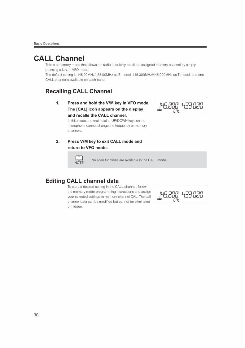
This is a memory mode that allows the radio to quickly recall the assigned memory channel by simply
pressing a key, in VFO mode.
The default setting is 145.00MHz/435.00MHz as E-model, 145.000MHz/445.000MHz as T-model, and one
CALL channelis available on each band.
1. Press and hold the V/M key in VFO mode. The [CAL] icon appears on the display and recalls the CALL channel. In this mode, the main dial or UP/DOWN keys on the
microphone cannot change the frequency or memory
channels.
2. Press V/M key to exit CALL mode and return to VFO mode.
NOTENo scan functions are available in the CALL mode.
To store a desired setting in the CALL channel, follow
the memory mode programming instructions and assign
your selected settings to memory channel CAL. The call
channel data can be modified but cannot be eliminated
or hidden.

31
Basic Operations
1. Be sure to have the unit connected to an appropriate antenna, powered on, set the audio volume and squelch level properly on both the MAIN and SUB bands.
2. Select the desired band and browse frequencies or select desired frequency to listen to ongoing communications. The S-meter shows relative signal strength when the radio detects an incoming signal, and the RX indicator lamp (green) turns on.
3. If the S-meter indicates an incoming signal but nothing is heard from the speaker, check the audio level, squelch level, and CTCSS/DCS decoding status.
This function is used to listen to weak signals. The
monitor function operates irrespective of Tone squelch /
DCS functions setting.
1. Select desired band as MAIN. Press FUNC key then press MW key while [FUNC] appears on the display. Regardless of squelch level, Tone squelch and DCS
setting, squelch on the MAIN side will open.
2. Press any key on the front panel to exit.
IMPORTANT The Monitor function only operates on the MAIN band.
S-meter

32
Basic Operations
This function is to monitor the transmitting frequency
instead of receiving frequency in repeater operation.
This technique is commonly used to check if it is
possible to communicate without using repeater by
monitoring the accessing station’s signal strength.
1. Set SHIFT rst. Press FUNC key then press MW key while [FUNC] appears on display.[ ] icon appears on the display to indicate that the
reverse function is activated and the squelch opens.
2. Pressing any key on the front panel will cancel the operation.
IMPORTANTThe Reverse function only operates on the MAIN band.Without SHIFT setting Monitor function will operate instead of Reverse function.
NOTE
Rotate squelch knob counterclockwise to monitor repeater’s down link.
In case tone squelch or DCS decoding is used, it is necessary to turn off
these functions to monitor.
1. Set the transmitting band to the MAIN side.
2. Check the system and monitor the frequency to make sure that you are not going to disturb any ongoing communications.
3. Press the PTT key on the microphone. The TX lamp (red) illuminates to show the unit is
transmitting.
4. Speak into the microphone in a normal voice while keeping the PTT key pressed. Hold the microphone approximately 5cm away from
your mouth. Speaking too close or too loud may result
in poor audio. Adjust microphone gain in set mode (Menu
03) when necessary.
Auto repeater setting
TX lamp

33
Basic Operations
5. Releasing the PTT key will complete the transmission and the unit will return to the receive mode.
NOTE
Pressing the DOWN key together with the PTT key will transmit the Tone
Burst signal.
Pressing the UP key with PTT key to transmit the Auto-dialer tones.
IMPORTANTIf you press the PTT key while out of the transmission frequency range, the [OFF] icon will appear on the display and no transmission will occur.
1. Press H/L key. The Output power switches among High, Middle and low. At middle power, the [ ], and at low power, the [ ]
illuminates. Nothing appears on the display at high
power. The default is high power.
The RF meter shows when transmitting at low
power, and at middle power, and
at high power.
Transmission Power
IMPORTANT The output power level cannot be changed during transmission. The output power level cannot be changed during scanning.
NOTEThe Middle output setting is adjustable in set mode (P.54); however, RF-meter
level indication will remain unchanged.
at low power
at middle power
at high power
34
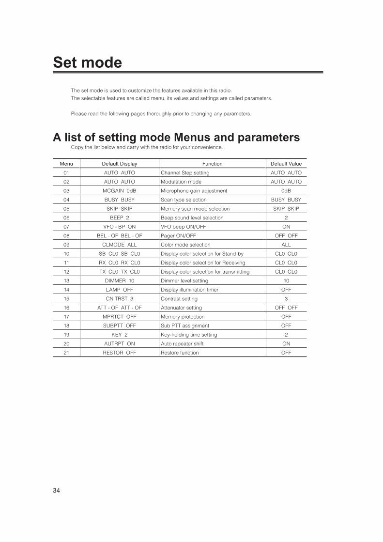
The set mode is used to customize the features available in this radio.
The selectable features are called menu, its values and settings are called parameters.
Please read the following pages thoroughly prior to changing any parameters.
Copy the list below and carry with the radio for your convenience.
Menu Default Display Function Default Value
01 AUTO AUTO Channel Step setting AUTO AUTO
02 AUTO AUTO Modulation mode AUTO AUTO
03 MCGAIN 0dB Microphone gain adjustment 0dB
04 BUSY BUSY Scan type selection BUSY BUSY
05 SKIP SKIP Memory scan mode selection SKIP SKIP
06 BEEP 2 Beep sound level selection 2
07 VFO - BP ON VFO beep ON/OFF ON
08 BEL - OF BEL - OF Pager ON/OFF OFF OFF
09 CLMODE ALL Color mode selection ALL
10 SB CL0 SB CL0 Display color selection for Stand-by CL0 CL0
11 RX CL0 RX CL0 Display color selection for Receiving CL0 CL0
12 TX CL0 TX CL0 Display color selection for transmitting CL0 CL0
13 DIMMER 10 Dimmer level setting 10
14 LAMP OFF Display illumination timer OFF
15 CN TRST 3 Contrast setting 3
16 ATT - OF ATT - OF Attenuator setting OFF OFF
17 MPRTCT OFF Memory protection OFF
18 SUBPTT OFF Sub PTT assignment OFF
19 KEY 2 Key-holding time setting 2
20 AUTRPT ON Auto repeater shift ON
21 RESTOR OFF Restore function OFF

35
Set mode
IMPORTANT
Some parameters are assigned to only left or right band and some of the parameters are not changeable. For details please refer to explanation of each menu in following pages.Some parameters are available only in VFO mode, or affects only temporary when operated in the memory mode.
1. Press and hold FUNC key to enter the Set mode. Menu number and parameter will appear on the display.
2. Select a menu by pressing left dial knob to decrease menu number or right dial knob to increase menu number. Press and hold the dial to automatically switch the menu number.
3. Rotate the dial to change settings. Rotate left dial to change parameters on left side and
right dial for right side.
Only the right dial may be available for certain menus.
A beep will sound when the left dial is operated in such
menu.
4. Pressing dial or UP/DOWN keys on the microphone will save the setting and enter the next menu.
5. Pressing any key other than the dial and UP/DOWN keys will complete the setting and the unit will exit the Set mode.
preference
A variety of features are available in the set mode menu. Please operate all
menu to learn how they work before you set the parameters of your. After
learning and practicing all available features, reset the radio by refering to P.75
then customize the parameters of your preference.
Default display

36
This is to select the channel step to be used in the VFO mode. Details are already explained
in P.21. The values are variable only in the VFO mode. Warning beep sounds when operated in
the memory mode.
This is to select the operating modulation mode. AM mode is not available for transmitting.
A narrow FM mode is becoming popular in amateur radio, and is also used in VoIP
communications.
The modulation level becomes half in narrow mode and receiving audio level increases. The
mode selection is stored independently for each band and memory channel.
This operation is possible in the memory mode but the change affects only temporary.
1. Press and hold FUNC key to enter the set mode. Press dial to select menu 02. Factory default setting is [Auto].
2. Rotate the dial to select FM, NFM, AM or NAM. When NFM or NAM selected, Nar will appear on the display.
3. Repeat the same operation by selecting another side of VFO if the same mode is always desired when operating the same band.
4. Press any key to set and exit, or press the dial or UP/DOWN keys to set and move to another menu.
1. Press and hold FUNC key to enter the set mode. Press dial to select menu 03. Factory default setting is [0dB]. This value becomes effective regardless of the band or VFO.
2. Rotate the right dial to select a value between -23dB and +23dB. Selecting (-) will decrease and (+) will increase microphone gain. The microphone gain is adjustable while transmitting.
NAMAMNFMFMAUTO

37
Set mode menu
3. Press any key except PTT to set and exit, or press the dial or UP/DOWN keys to set and move to another menu.
IMPORTANT Pressing PTT switch will not exit the set mode setting in this menu.
This is to select the scan resume condition. The BUSY setting resumes scanning when
received signal is gone and the TIME setting allows the radio to resume scanning after 5, 10,
20,30 or 60 seconds. This parameter can be selected for both left and right VFO but cannot
be selected for each band.
1. Press and hold FUNC key to enter the set mode. Press dial to select menu 04. Factory default setting is [BUSY].
2. By rotating the dial, the display changes as shown.
3. Select a desired parameter.
4. Repeat the same operation by selecting another side of VFO if the same mode is always desired whichever the VFO you use.
BUSY TIME05 TIME10 TIME20 TIME30 TIME60(seconds)
5. Press any key to set and exit, or press the dial or UP/DOWN keys to set and move to another menu.
Use this function to select memory scan conditions. (P.59)
This parameter can be selected for both left and right VFO but cannot be selected for each
band.
1. Press and hold FUNC key to enter the set mode. Press dial to select menu 05. Factory default setting is [SKIP].
ALLSKIP FAV
38
Set mode menu
2. Rotate the dial to select a desired parameter.SKIP : Memory-scans skipping SKIP channels.
ALL : Scans all memory channels regardless of SKIP/
FAV setting.
FAV : Memory-scan only favorite channels.
3. Press any key to set and exit, or press the dial or UP/DOWN keys to set and move to another menu.
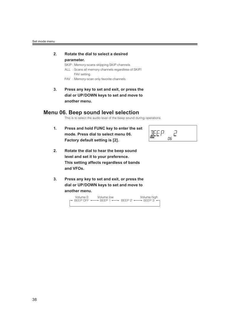
This is to select the audio level of the beep sound during operations.
1. Press and hold FUNC key to enter the set mode. Press dial to select menu 06. Factory default setting is [2].
2. Rotate the dial to hear the beep sound level and set it to your preference. This setting affects regardless of bands and VFOs.
3. Press any key to set and exit, or press the dial or UP/DOWN keys to set and move to another menu.
Volume 0 Volume low Volume high
39
Set mode menu
A beep sounds at 500KHz/1MHz order while scanning or selecting the frequency. Such beep
can be muted.
1. Press and hold FUNC key to enter the set mode. Press dial to select menu 07. Factory default setting is [ON].
2. Rotate the right dial to select a desired parameter. This setting affects regardless of the band or VFO.
3. Press any key to set and exit, or press the dial or UP/DOWN keys to set and move to another menu.
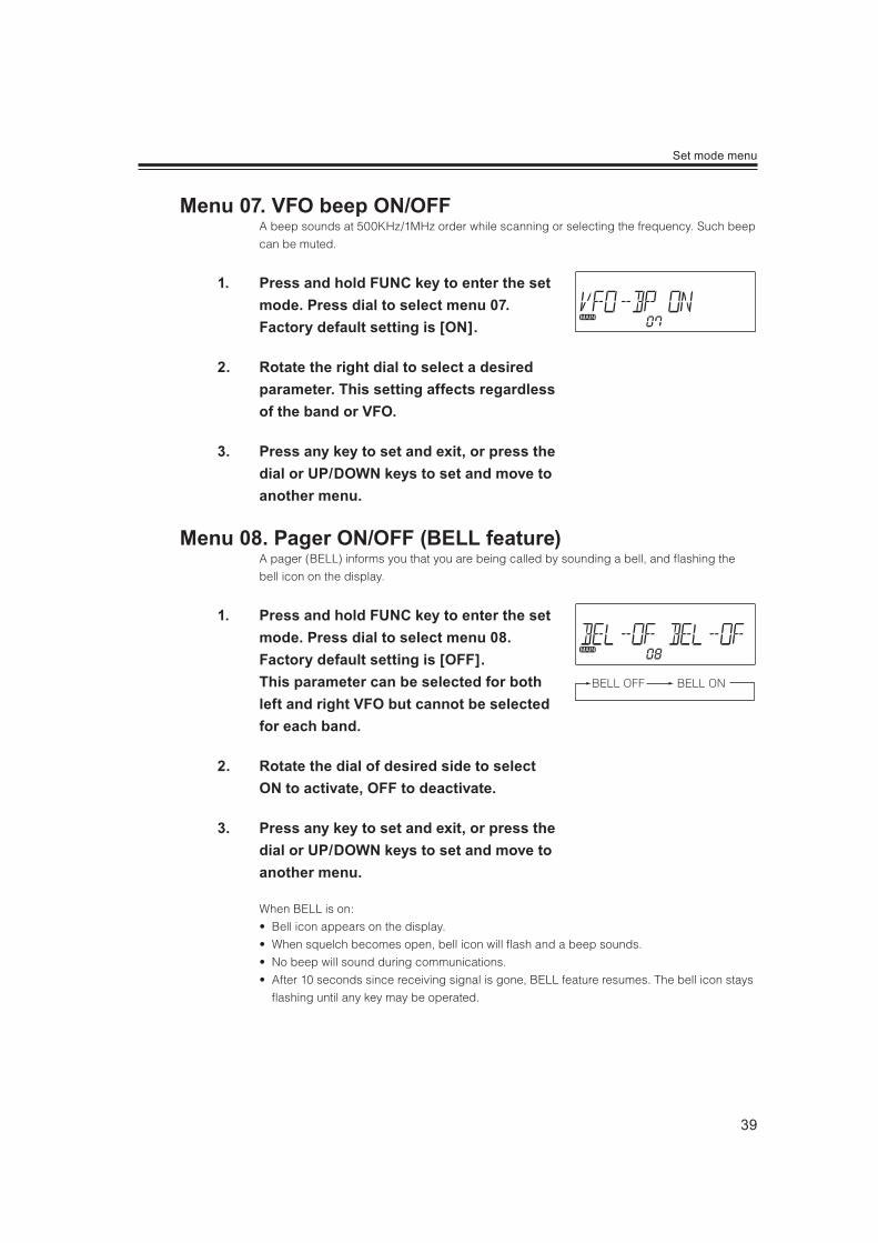
A pager (BELL) informs you that you are being called by sounding a bell, and flashing the
bell icon on the display.
1. Press and hold FUNC key to enter the set mode. Press dial to select menu 08. Factory default setting is [OFF]. This parameter can be selected for both left and right VFO but cannot be selected for each band.
2. Rotate the dial of desired side to select ON to activate, OFF to deactivate.
3. Press any key to set and exit, or press the dial or UP/DOWN keys to set and move to another menu.
When BELL is on:
ell icon appears on the display.
hen squelch becomes open, bell icon will flash and a beep sounds.
o beep will sound during communications.
fter 10 seconds since receiving signal is gone, BELL feature resumes. The bell icon stays
flashing until any key may be operated.

40
Set mode menu
This is the mode to select color mode for various conditions.
This is to determine the display color assignment of Stand-by, Receiving and Transmitting
status to be set in the following menu 10 to 12.
1. Press and hold FUNC key to enter the set mode. Press dial to select menu 09.
2. By rotating the right dial, the display changes as shown.
3. Press any key to set and exit, or press the dial or UP/DOWN keys to set and move to another menu.
ALL : This is to fix the colors of the left and right side of the display, regardless of the
bands, MAIN/SUB setting or VFO/memory modes. This is suitable for users who
do not care details, but just use a fixed color setting on the left and right side of
the display.
MEMORY : This is for users who prefer to fix the colors in accordance with bands,
regardless of the side of the display, or to use programed color parameters in
memory channels.
Like channel steps and modulation mode settings, left/right and bands can be
set independently, and programmed into the memory channels.
GRADTN : Gradation mode. Color on the display changes automatically.
RAINBW : Rainbow colors will move from left to right.
NOTEGRADTN and RAINBW mods are fixed and not available for customization
being or programmed into memory channels.
GRADTNMEMORYALL RAINBW

41
Set mode menu
1. Press and hold FUNC key to enter the set mode. Press dial to select menu 10 to set the display color of Stand-by state.
2. Rotate either left or right dial you wish to edit the display color. The color selection is affected immediately. See the list below for available colors in menu 10 ~ 12.
3. Press any key to set and exit, or press the dial or UP/DOWN keys to set and move to another menu.CL0 : White CL5 : PurpleCL1 : Red CL6 : Light BlueCL2 : Green CL7 : OrangeCL3 : Blue CL8 : PinkCL4 : Yellow CL9 : Light Green
NOTEBy operating RGB color setting on P.63, CLA ~ CLF parameters will be added
in menu 10, 11 and 12..
1. Press and hold FUNC key to enter the set mode. Press dial to select menu 11 to set the display color of Receiving state.
2. Rotate either left or right dial you wish to edit the display color. The color selection is affected immediately.
3. Press any key to set and exit, or press the dial or UP/DOWN keys to set and move to another menu.
SB CL0 SB CL9
RX CL0 RX CL9

42
Set mode menu
1. Press and hold FUNC key to enter the set mode. Press dial to select menu 12 to set the display color of Transmitting state.
2. Rotate either left or right dial you wish to edit the display color. The color selection is affected immediately.
3. Press any key to set and exit, or press the dial or UP/DOWN keys to set and move to another menu.
Select the brightness of the display. 10 is brightest, 0 is dim.
1. Press and hold FUNC key to enter the set mode. Press dial to select menu 13.
2. Rotate the right dial to select the brightness you like. The level 10 is brightest, level 0 is dim. This value becomes effective regardless of band and VFO.
3. Press any key to set and exit, or press the dial or UP/DOWN keys to set and move to another menu.
TX CL0 TX CL9
DIMMER 0 DIMMER 10

43
Set mode menu
The display illuminates brighter for a period of time set in here. The brightness is 5 levels
higher than the value set in menu 13. This value becomes effective regardless of band and
VFO.
1. Press and hold FUNC key to enter the set mode. Press dial to select menu 14.
2. Select a timer value by rotating the right dial. Available parameters are shown below.
3. Press any key to set and exit, or press the dial or UP/DOWN keys to set and move to another menu.
OFF 2010753
NOTE
Select the dimmer level 0 in previous menu, so that the display illuminates
only when a key is operated except PTT. This setting mey be comfortable
while driving at night.
This is to set the contrast value of displayed characters. The change may not be very obvious
depending on the display color you selected.
1. Press and hold FUNC key to enter the set mode. Press dial to select menu 15. Factory default setting is [3].
2. Select a value by rotating the right dial. Available parameters are 1 to 5. This value becomes effective regardless of band and VFO.
3. Press any key to set and exit, or press the dial or UP/DOWN keys to set and move to another menu.

44
Set mode menu
Attenuator reduces sensitivity intentionally. When a very strong signal
is being received in near-by frequency, it may interfere the signal you
are receiving. By reducing the sensitivity, such interference may be gone.
1. Press and hold FUNC key to enter the set mode. Press dial to select menu 16.
2. Rotate either left or right dial to set the parameter. Available parameters are shown below. This function is assignable to left and right VFOs separately, but not to each band.
3. Press any key to set and exit, or press the dial or UP/DOWN keys to set and move to another menu.
FF : Attenuator function is disabled.
Q : The attenuator functions in relation with the squelch level. Rotate the dial clockwise
until ATT is displayed and to obtain an appropriate level. The maximum level is about
10dB.
The squelch level remains at a center-position of the squelch knob while ATT is
activated.
N : 10dB attenuation is activated always. When attenuator is ON, ATT appears on the
display.
This is to prevent important data from being deleted or overwritten accidentally.
1. Press and hold FUNC key to enter the set mode. Press dial to select menu 17. Factory default setting is [OFF].
2. Rotate the right dial to select ON or OFF. OFF allows overwriting and editing the memory channels, ON to prohibit. This setting becomes effective regardless of bands and VFOs.
3. Press any key to set and exit, or press the dial or UP/DOWN keys to set and move to another menu.
45
Set mode menu
NOTE
Memory reset (P.75) will delete memory channels data even when memory
protection is set ON.
Channel data can be temporary edited during operations even the
protection is ON, but won't be stored and will reset to original data when
you turn off or move to another memory channel.
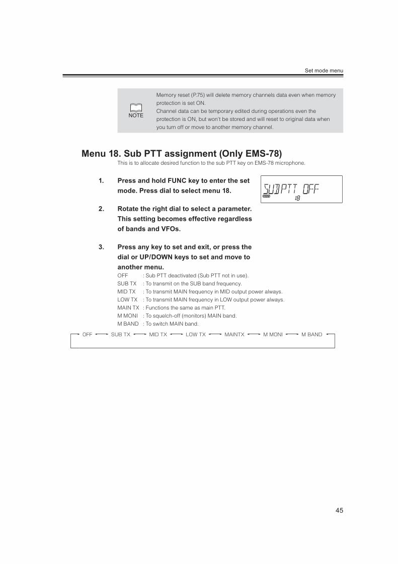
This is to allocate desired function to the sub PTT key on EMS-78 microphone.
1. Press and hold FUNC key to enter the set mode. Press dial to select menu 18.
2. Rotate the right dial to select a parameter. This setting becomes effective regardless of bands and VFOs.
3. Press any key to set and exit, or press the dial or UP/DOWN keys to set and move to another menu.OFF : Sub PTT deactivated (Sub PTT not in use).
SUB TX : To transmit on the SUB band frequency.
MID TX : To transmit MAIN frequency in MID output power always.
LOW TX : To transmit MAIN frequency in LOW output power always.
MAIN TX : Functions the same as main PTT.
M MONI : To squelch-off (monitors) MAIN band.
M BAND : To switch MAIN band.
OFF SUB TX MID TX LOW TX MAINTX M MONI M BAND
46
Set mode menu
This is to change the time for pushing and holding keys. Shorter value allows faster
operations, but may cause erroneous key operations. This value affects press-and-hold key
operations such as key-lock, activating scans,memory programming etc.
1. Press and hold FUNC key to enter the set mode. Press dial to select menu 19. Factory default setting is [2] seconds.
2. Rotate the right dial to select a value. Available values are 1 to 5 in seconds. This setting becomes effective regardless of bands and VFOs.
3. Press any key to set and exit, or press the dial or UP/DOWN keys to set and move to another menu.
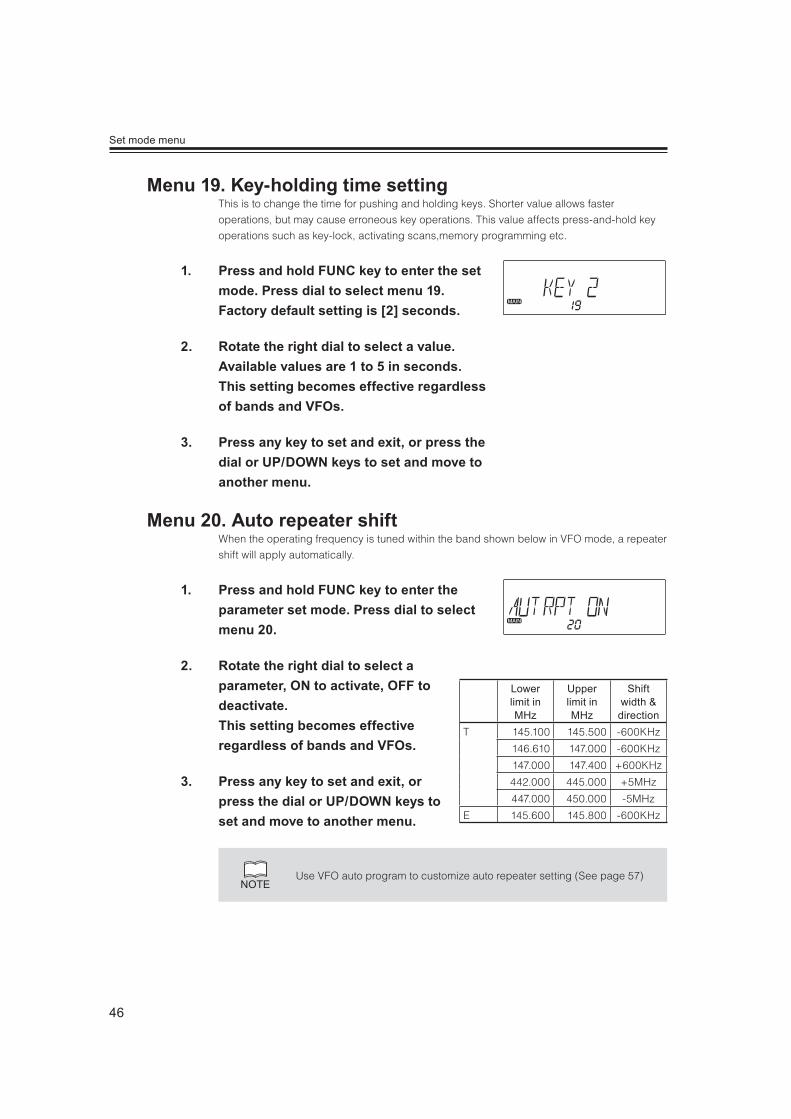
When the operating frequency is tuned within the band shown below in VFO mode, a repeater
shift will apply automatically.
1. Press and hold FUNC key to enter the parameter set mode. Press dial to select menu 20.
2. Rotate the right dial to select a parameter, ON to activate, OFF to deactivate. This setting becomes effective regardless of bands and VFOs.
3. Press any key to set and exit, or press the dial or UP/DOWN keys to set and move to another menu.
NOTEUse VFO auto program to customize auto repeater setting (See page 57)
Lower limit in MHz
Upper limit in MHz
Shift width & direction
T 145.100 145.500 -600KHz
146.610 147.000 -600KHz
147.000 147.400 +600KHz
442.000 445.000 +5MHz
447.000 450.000 -5MHz
E 145.600 145.800 -600KHz
47
Set mode menu
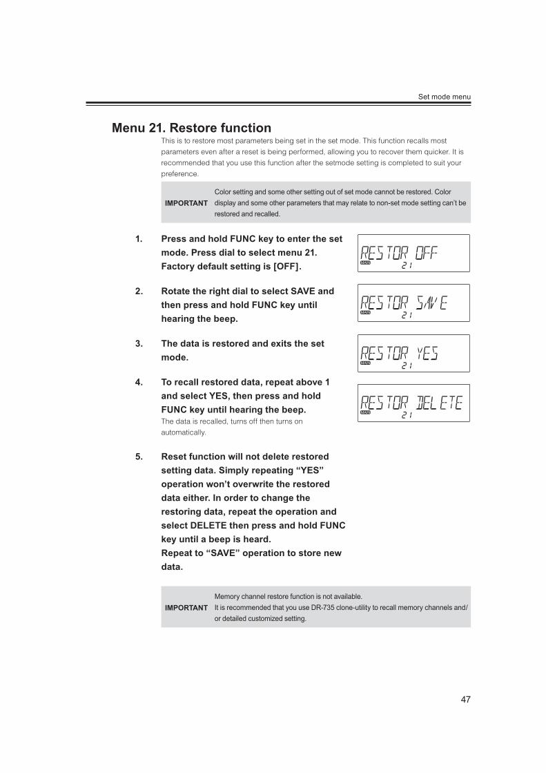
This is to restore most parameters being set in the set mode. This function recalls most
parameters even after a reset is being performed, allowing you to recover them quicker. It is
recommended that you use this function after the setmode setting is completed to suit your
preference.
IMPORTANTColor setting and some other setting out of set mode cannot be restored. Color display and some other parameters that may relate to non-set mode setting can’t be restored and recalled.
1. Press and hold FUNC key to enter the set mode. Press dial to select menu 21. Factory default setting is [OFF].
2. Rotate the right dial to select SAVE and then press and hold FUNC key until hearing the beep.
3. The data is restored and exits the set mode.
4. To recall restored data, repeat above 1 and select YES, then press and hold FUNC key until hearing the beep.The data is recalled, turns off then turns on
automatically.
5. Reset function will not delete restored setting data. Simply repeating “YES” operation won’t overwrite the restored data either. In order to change the restoring data, repeat the operation and select DELETE then press and hold FUNC key until a beep is heard. Repeat to “SAVE” operation to store new data.
IMPORTANTMemory channel restore function is not available. It is recommended that you use DR-735 clone-utility to recall memory channels and/or detailed customized setting.
48
Set mode menu
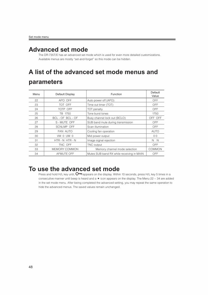
The DR-735T/E has an advanced set mode which is used for even more detailed customizations.
Available menus are mostly “set-and-forget” so this mode can be hidden.
Menu Default Display Function Default Value
22 APO OFF Auto power off (APO) OFF
23 TOT OFF Time out timer (TOT) OFF
24 TOTP OFF TOT penalty OFF
25 TB 1750 Tone burst tones 1750
26 BCL - OF BCL - OF Busy channel lock out (BCLO) OFF OFF
27 S - MUTE OFF SUB band mute during transmission OFF
28 SCNLMP OFF Scan illumination OFF
29 FAN AUTO Cooling fan operation AUTO
30 VM 0 UM 0 Mid power output 0 0
31 HTR - N HTR - N Image signal rejection N N
32 TNC OFF TNC output OFF
33 MEMORY COMMON Memory channel mode selection COMMON
34 AFMUTE OFF Mutes SUB band RX while receiving in MAIN OFF
Press and hold H/L key until, appears on the display. Within 10 seconds, press H/L key 5 times in a
consecutive manner until beep is heard and a icon appears on the display. The Menu 22 ~ 34 are added
in the set mode menu. After being completed the advanced setting, you may repeat the same operation to
hide the advanced menus. The saved values remain unchanged.
49
Set mode menu
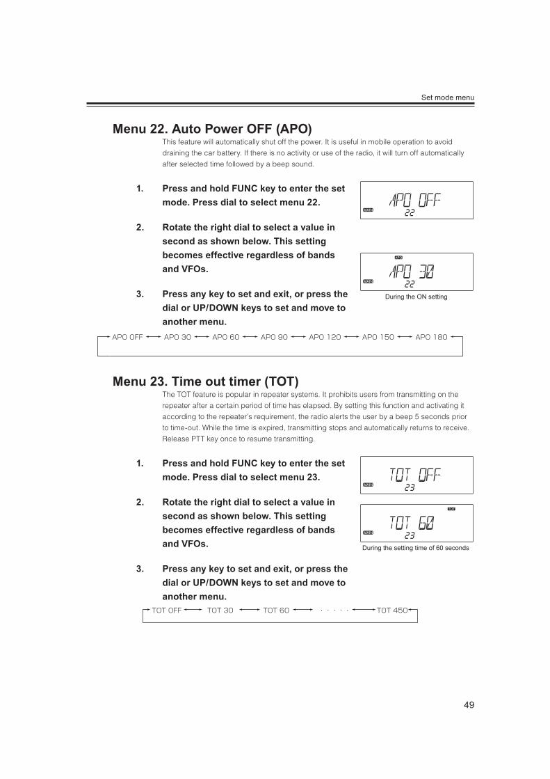
This feature will automatically shut off the power. It is useful in mobile operation to avoid
draining the car battery. If there is no activity or use of the radio, it will turn off automatically
after selected time followed by a beep sound.
1. Press and hold FUNC key to enter the set mode. Press dial to select menu 22.
2. Rotate the right dial to select a value in second as shown below. This setting becomes effective regardless of bands and VFOs.
3. Press any key to set and exit, or press the dial or UP/DOWN keys to set and move to another menu.
APO OFF APO 30 APO 60 APO 90 APO 120 APO 150 APO 180
The TOT feature is popular in repeater systems. It prohibits users from transmitting on the
repeater after a certain period of time has elapsed. By setting this function and activating it
according to the repeater’s requirement, the radio alerts the user by a beep 5 seconds prior
to time-out. While the time is expired, transmitting stops and automatically returns to receive.
Release PTT key once to resume transmitting.
1. Press and hold FUNC key to enter the set mode. Press dial to select menu 23.
2. Rotate the right dial to select a value in second as shown below. This setting becomes effective regardless of bands and VFOs.
3. Press any key to set and exit, or press the dial or UP/DOWN keys to set and move to another menu.
During the ON setting
During the setting time of 60 seconds
50
Set mode menu
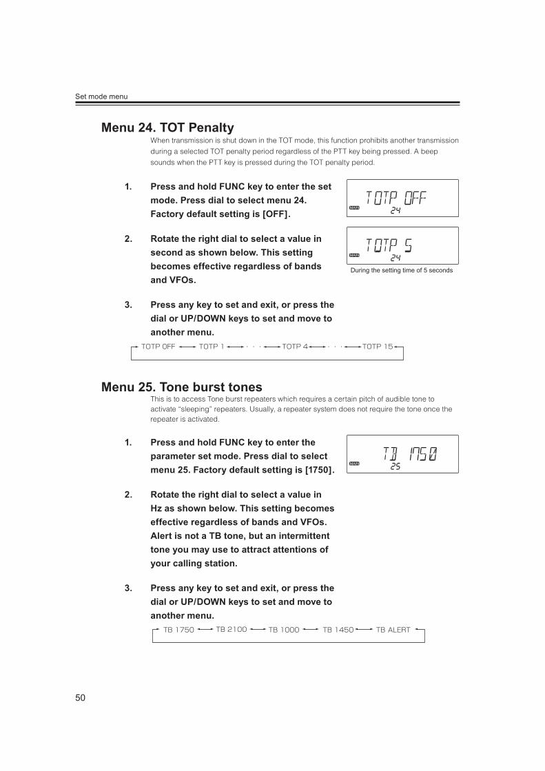
When transmission is shut down in the TOT mode, this function prohibits another transmission
during a selected TOT penalty period regardless of the PTT key being pressed. A beep
sounds when the PTT key is pressed during the TOT penalty period.
1. Press and hold FUNC key to enter the set mode. Press dial to select menu 24. Factory default setting is [OFF].
2. Rotate the right dial to select a value in second as shown below. This setting becomes effective regardless of bands and VFOs.
3. Press any key to set and exit, or press the dial or UP/DOWN keys to set and move to another menu.
This is to access Tone burst repeaters which requires a certain pitch of audible tone to activate “sleeping” repeaters. Usually, a repeater system does not require the tone once the repeater is activated.
1. Press and hold FUNC key to enter the parameter set mode. Press dial to select menu 25. Factory default setting is [1750].
2. Rotate the right dial to select a value in Hz as shown below. This setting becomes effective regardless of bands and VFOs. Alert is not a TB tone, but an intermittent tone you may use to attract attentions of your calling station.
3. Press any key to set and exit, or press the dial or UP/DOWN keys to set and move to another menu.
During the setting time of 5 seconds

51
Set mode menu
This function prohibits transmission as long as there is a signal on the receiving frequency.
The default is BCLO-OFF, which is the off position. By activating this function, the radio
transmits only when:
1. No signal is received (BUSY icon is gone) on the receiving frequency.
2. The tone-squelch is not opened by receiving the corresponding CTCSS tone.
3. As above, with DCS code.
therwise a beep sound and the unit does not transmit even when the PTT is pressed.
1. Press and hold FUNC key to enter the set mode. Press dial to select menu 26. Factory default setting is [OFF].
2. Rotate either left or right dial you wish to set the BCLO feature. BCLO can be set separately in VFOs, but not for each band.
3. Press any key to set and exit, or press the dial or UP/DOWN keys to set and move to another menu.
BCL-OF BCL-ON

52
Set mode menu
This is to operate as a semi-duplex radio, muting the sub band audio while transmitting in the
MAIN band.
1. Press and hold FUNC key to enter the set mode. Press dial to select menu 27. Factory default setting is [OFF].
2. Rotate the right dial and select ON to activate, OFF to deactivate. This setting becomes effective regardless of bands and VFOs.
3. Press any key to set and exit, or press the dial or UP/DOWN keys to set and move to another menu.
This is to illuminate the display at a maximum brightness for 2 seconds when a signal is
detected during scanning. Dimmer level should be set darker in advance to utilize this
feature.
1. Press and hold FUNC key to enter the set mode. Press dial to select menu 28. Factory default setting is [OFF].
2. Rotate the right dial and select ON to activate, OFF to deactivate.This setting becomes effective regardless of bands and VFOs.
3. Press any key to set and exit, or press the dial or UP/DOWN keys to set and move to another menu.
53
Set mode menu
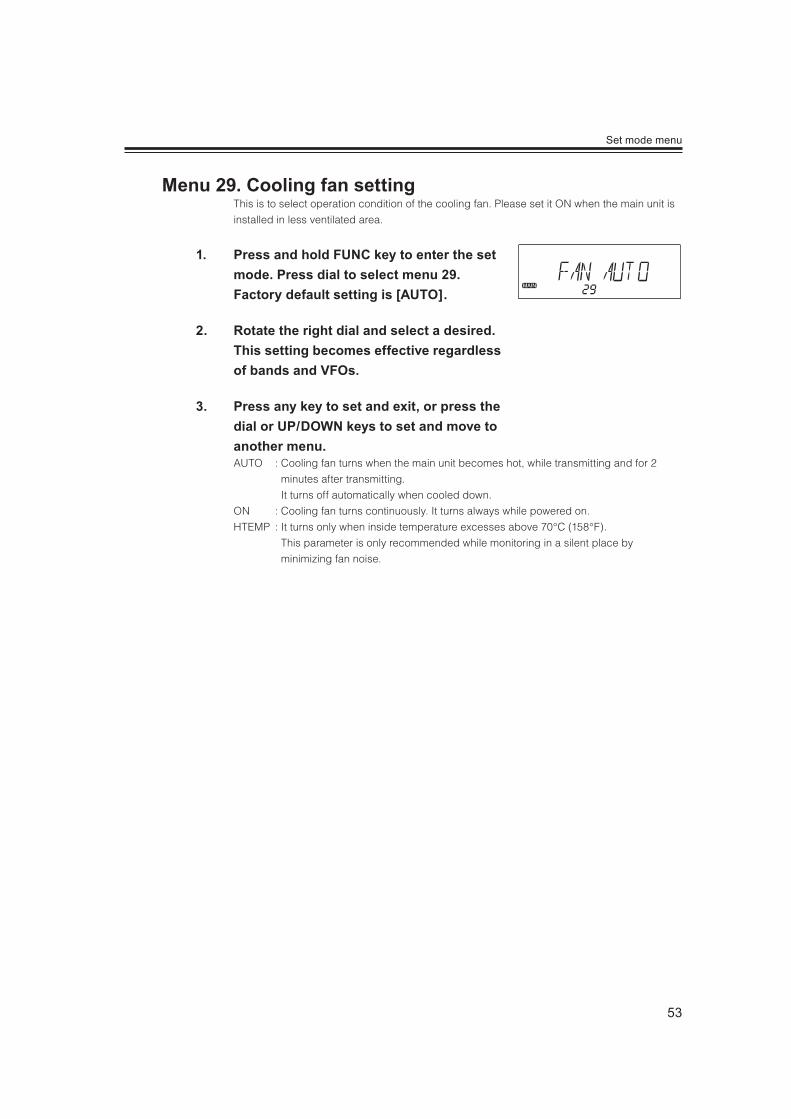
This is to select operation condition of the cooling fan. Please set it ON when the main unit is
installed in less ventilated area.
1. Press and hold FUNC key to enter the set mode. Press dial to select menu 29. Factory default setting is [AUTO].
2. Rotate the right dial and select a desired. This setting becomes effective regardless of bands and VFOs.
3. Press any key to set and exit, or press the dial or UP/DOWN keys to set and move to another menu.AUTO : Cooling fan turns when the main unit becomes hot, while transmitting and for 2
minutes after transmitting.
It turns off automatically when cooled down.
ON : Cooling fan turns continuously. It turns always while powered on.
HTEMP : It turns only when inside temperature excesses above 70°C (158°F).
This parameter is only recommended while monitoring in a silent place by
minimizing fan noise.

54
Set mode menu
This is to customize the Mid output power. The setting is assignable to VHF and UHF bands,
but not VFOs. Available levels are 21 and between 50 and 5 Watts. Default is zero, and
represents 20W.
Use of a power-meter and a dummy load is recommended for acurate adjustment.
1. Press and hold FUNC key to enter the set mode. Press dial to select menu 30.
2. Rotate the left dial for VHF, right for UHF. Negative icon represents lower output, positive for higher output.-10 is lowest (approx. 5 W), +10 is highest (approx.50 W). You can transmit while tuning; use VOL knobs to switch MAIN band.
3. Press any key other than PTT to set and exit, or press the dial or UP/DOWN keys to set and move to another menu.
IMPORTANTThis operation is possible only in the transmitting range and a waring beep sounds otherwise.
This feature may eliminate interference caused by unwanted image signal being received
such as hearing FM braodcast in amateur radio bands.
NOTEThis function is not a noise blanker and may not be effective in all cases of
image signal interferences.
1. Press and hold FUNC key to enter the set mode. Press dial to select menu 31. Factory default setting is [N].
2. Rotate either left or right dial you wish to apply change and select R (reverse). This is selectable separately in VFOs, but not for each
band.
3. Press any key other than PTT to set and exit, or press the dial or UP/DOWN keys to set and move to another menu.

55
Set mode menu
The DIN connector on rear panel outputs signals necessary to operate devices like external
TNC and VoIP interface units in TNC mode.
IMPORTANT
Due to restrictions on the devices used in this radio, a data communication higher than 4800bps (like packet mode) is NOT possible, even the external device supports higher speed. TNC mode is available only to the RIGHT VFO.
1. Press and hold FUNC key to enter the set mode. Press dial to select menu 32. Factory default setting is [OFF].
2. Rotate the right dial to select ON to activate TNC mode, OFF to deactivate. TNC icon appears when activated.
3. Press any key other than PTT to set and exit, or press the dial or UP/DOWN keys to set and move to another menu.

56
Set mode menu
This is to select memory channel mode. 3 different modes are available.
1. Press and hold FUNC key to enter the set mode. Press dial to select menu 33. Factory default setting is [COMMON].
2. Rotate the right dial to select desired memory mode as explained below.COMMON : Only using common memory channels (000 to 999)
L/R : Only using individual right and left memory channels (L00 to L99, R00 to R99)
ALL : Using both common and individual memory channels (000 to 999, L00 to L99/
R00 to R99)
3. Press any key other than PTT to set and exit, or press the dial or UP/DOWN keys to set and move to another menu.
NOTE rogrammed memory channels won’t be deleted by changing memory
channel mode.
Easy memory programming is available in both COMMON and L/R modes.
In case ALL, easy programming is available only to COMMON channels.
This is like a semi-duplex transceiver to mute the sub-band receive while receiving in the
MAIN band.
1. Press and hold FUNC key to enter the set mode. Press dial to select menu 34. Factory default setting is [OFF]. This setting becomes effective regardless of bands and VFOs.
2. Select On to activate, OFF to deactivate by rotating the dial.

57
This is to use the unit as a single-band radio by eliminating the display on the opposite side.
1. Press FUNC key and while [FUNC] appears on the display, press VOL knob of the desired side to operate. The display of the opposite side will disappear.
2. Press the VOL knob of opposite side to switch the band to operate. Press FUNC then press a VOL knob to resume a dual-band operation.
This is a “customized AUTO repeater” feature. Parameters set in this feature has a priority over the
conventional AUTO-repeater setting, and can be activated both at the same time.
The parameters available for this functions are the upper/lower limit of the range, shift direction, offset width,
and CTCSS/DCS encode/decode setting. (P.65)
1. In VFO mode, tune to the lower limit frequency and set the offset direction/width, tone status as preferred. Press FUNC key and rotate the dial of the same VFO you operated to select APL. Press the V/M key of the same side to save.
2. Tune to the higher limit frequency, repeat above 1 to select APH and set. APH setting is valid only the frequency and other parameters will be disregarded. APH frequency should be higher than APL otherwise doesn’t work. APL and APH can’t accept temporary change of the programmed data.
3. Disable shift and tone settings operated in above 1. Move to the AUTO-program range and see if desired setting is automatically applied.
When 439.000MHz 88.5Hz ENC-5.000MHz shift is set in APL
APH is set to 439.980MHz
Shows an example within VFO auto-program setting
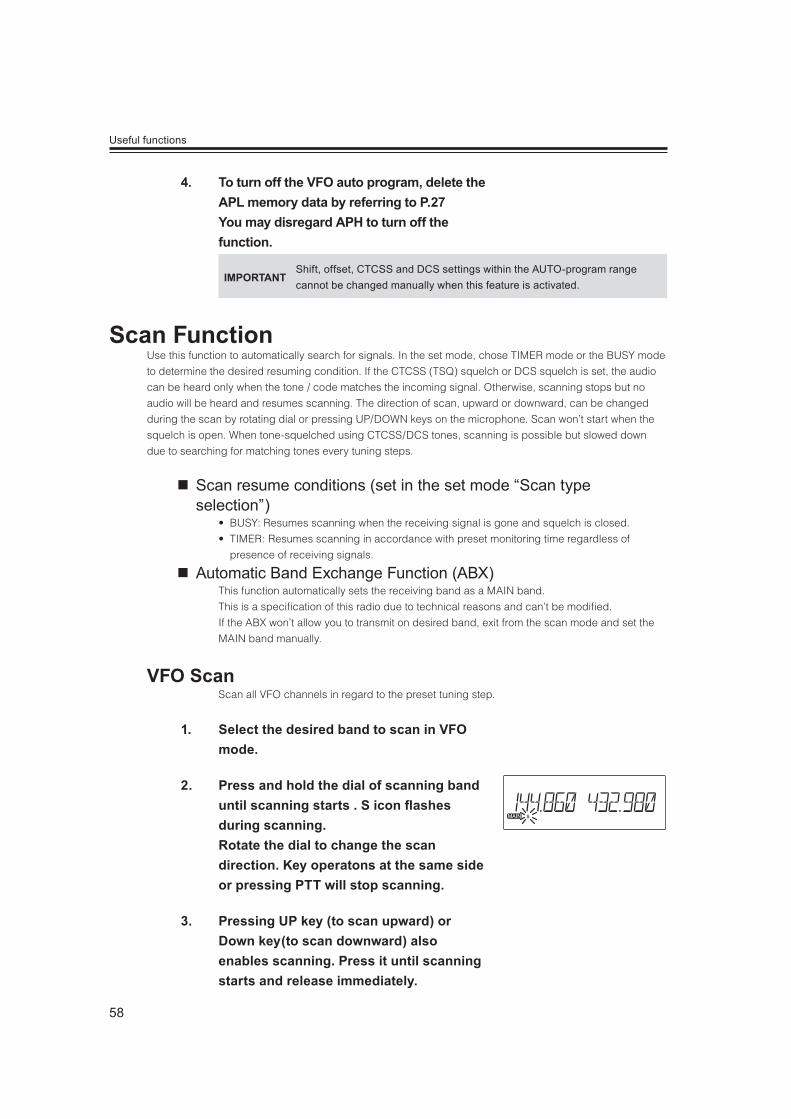
58
Useful functions
4. To turn off the VFO auto program, delete the APL memory data by referring to P.27 You may disregard APH to turn off the function.
IMPORTANTShift, offset, CTCSS and DCS settings within the AUTO-program range cannot be changed manually when this feature is activated.
Use this function to automatically search for signals. In the set mode, chose TIMER mode or the BUSY mode
to determine the desired resuming condition. If the CTCSS (TSQ) squelch or DCS squelch is set, the audio
can be heard only when the tone / code matches the incoming signal. Otherwise, scanning stops but no
audio will be heard and resumes scanning. The direction of scan, upward or downward, can be changed
during the scan by rotating dial or pressing UP/DOWN keys on the microphone. Scan won’t start when the
squelch is open. When tone-squelched using CTCSS/DCS tones, scanning is possible but slowed down
due to searching for matching tones every tuning steps.
Scan resume conditions (set in the set mode “Scan type selection”)
USY: Resumes scanning when the receiving signal is gone and squelch is closed.
IMER: Resumes scanning in accordance with preset monitoring time regardless of
presence of receiving signals.
Automatic Band Exchange Function (ABX)This function automatically sets the receiving band as a MAIN band.
This is a specification of this radio due to technical reasons and can’t be modified.
If the ABX won’t allow you to transmit on desired band, exit from the scan mode and set the
MAIN band manually.
Scan all VFO channels in regard to the preset tuning step.
1. Select the desired band to scan in VFO mode.
2. Press and hold the dial of scanning band until scanning starts . S icon ashes during scanning. Rotate the dial to change the scan direction. Key operatons at the same side or pressing PTT will stop scanning.
3. Pressing UP key (to scan upward) or Down key(to scan downward) also enables scanning. Press it until scanning starts and release immediately.
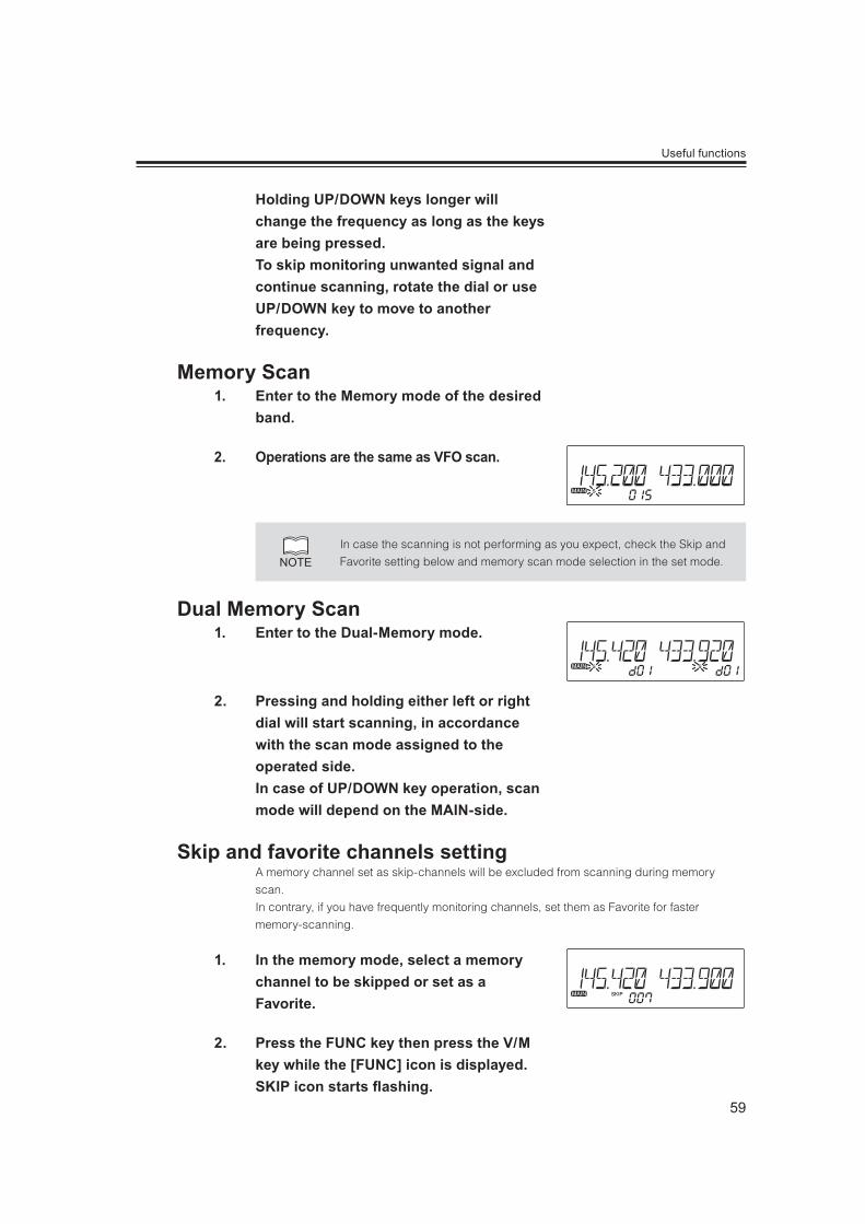
59
Useful functions
Holding UP/DOWN keys longer will change the frequency as long as the keys are being pressed. To skip monitoring unwanted signal and continue scanning, rotate the dial or use UP/DOWN key to move to another frequency.
1. Enter to the Memory mode of the desired band.
2. Operations are the same as VFO scan.
NOTEIn case the scanning is not performing as you expect, check the Skip and
Favorite setting below and memory scan mode selection in the set mode.
1. Enter to the Dual-Memory mode.
2. Pressing and holding either left or right dial will start scanning, in accordance with the scan mode assigned to the operated side. In case of UP/DOWN key operation, scan mode will depend on the MAIN-side.
A memory channel set as skip-channels will be excluded from scanning during memory
scan.
In contrary, if you have frequently monitoring channels, set them as Favorite for faster
memory-scanning.
1. In the memory mode, select a memory channel to be skipped or set as a Favorite.
2. Press the FUNC key then press the V/M key while the [FUNC] icon is displayed. SKIP icon starts ashing.

60
Useful functions
3. Rotate a dial to select either SKIP or ♥ for favorite.Press V/M key to save. The icon will stop ashing. Repeat above 2 again to cancel the setting. The icon will disappear.
4. Select SKIP or FAV in set mode menu 05 and perform the memory scanning.
This is a type of VFO scan, and scans only the designated frequency range of the VFO sets
into the P*A and P*B channels, This feature is refered to as “Search” and can be set 5 pairs in
each band.
This program scan will operate under VFO setting, regardless of memory setting of the
P*A/P*B memory setting.
P1A P1B
Airband VHF UHF
P2A P2B P3B P4AP3A P4B P5A P5B
1. Enter the VFO mode and set the P A and P B frequencies into the designated memory channels. Refer to Memory setting P.23 for details. It doesn’t matter which is higher and lower limits, but you should always make a pair to determine the edge of scanning range.
2. Return to the the VFO mode by pressing the V/M key of the band to be scanned.
3. Press FUNC key and while F icon is displayed, press the dial. PS- and a number appears.
4. Rotate the dial or UP/DOWN keys on the microphone to select a pair number. Press the dial to start scanning.
5. Press any key other than the UP/DOWN keys to stop.
NOTEProgrammed scan can't be performed in both bands at the same time.
Program Scan is going
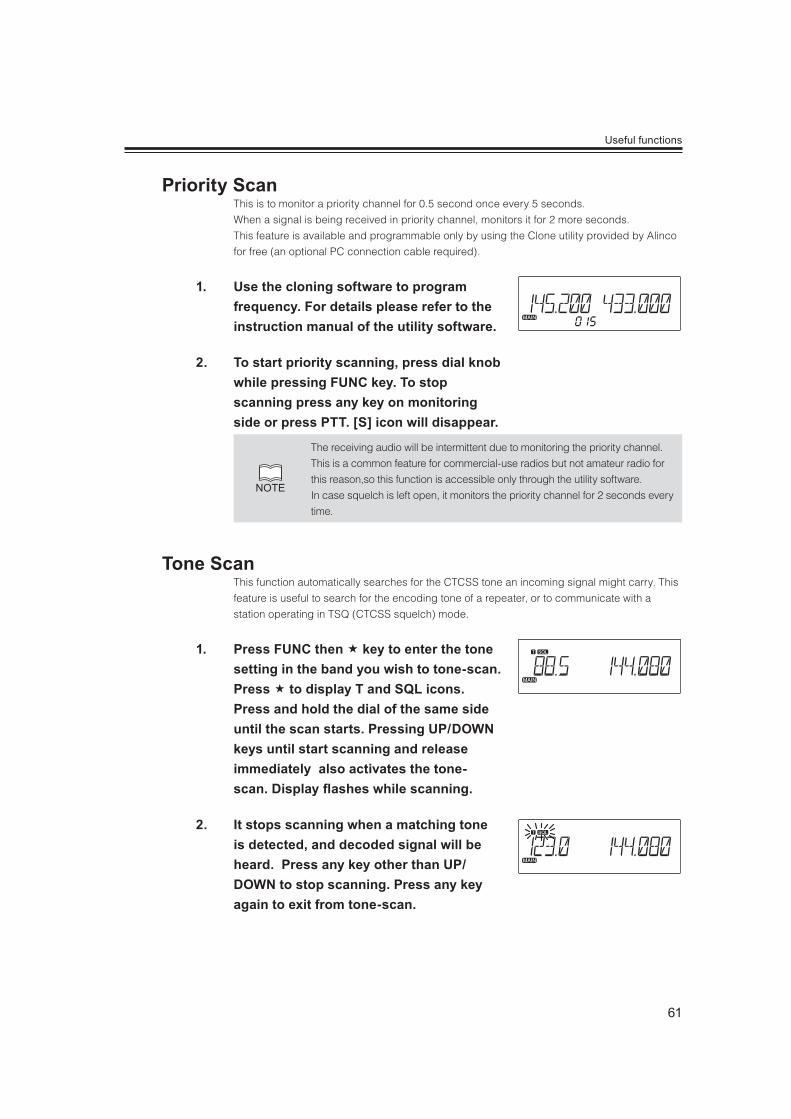
61
Useful functions
This is to monitor a priority channel for 0.5 second once every 5 seconds.
When a signal is being received in priority channel, monitors it for 2 more seconds.
This feature is available and programmable only by using the Clone utility provided by Alinco
for free (an optional PC connection cable required).
1. Use the cloning software to program frequency. For details please refer to the instruction manual of the utility software.
2. To start priority scanning, press dial knob while pressing FUNC key. To stop scanning press any key on monitoring side or press PTT. [S] icon will disappear.
NOTE
The receiving audio will be intermittent due to monitoring the priority channel.
This is a common feature for commercial-use radios but not amateur radio for
this reason,so this function is accessible only through the utility software.
In case squelch is left open, it monitors the priority channel for 2 seconds every
time.
This function automatically searches for the CTCSS tone an incoming signal might carry. This
feature is useful to search for the encoding tone of a repeater, or to communicate with a
station operating in TSQ (CTCSS squelch) mode.
1. Press FUNC then key to enter the tone setting in the band you wish to tone-scan. Press to display T and SQL icons. Press and hold the dial of the same side until the scan starts. Pressing UP/DOWN keys until start scanning and release immediately also activates the tone-scan. Display ashes while scanning.
2. It stops scanning when a matching tone is detected, and decoded signal will be heard. Press any key other than UP/DOWN to stop scanning. Press any key again to exit from tone-scan.

62
Useful functions
This function automatically searches for the DCS tone an incoming signal might carry. This
feature is useful to search for the encoding tone of a repeater, or to communicate with a
station operating in DCS (Digital Code Squelch) mode.
1. Press FUNC then key to enter the tone setting in the band you wish to DCS-scan. Press to display DCS icon. Press and hold the dial of the same side until the scan starts. Pressing UP/DOWN keys until start scanning and release immediately also activates the DCS scan. Display ashes while scanning.
2. It stops scanning when a matching code is detected, and decoded signal will be heard. Press any key other than UP/DOWN to stop scanning. Press any key again to exit from DCS scan.
This will lock the keys to avoid unintentional key operations.
1. Press and hold H/L key.The [ ] icon appears on the display.
2. Repeat above to unlock.
3. All keys and dial functions will remain locked except below in Key lock state.PTT
H/L key to cancel this function
Squelch and volume
UP/DOWN keys
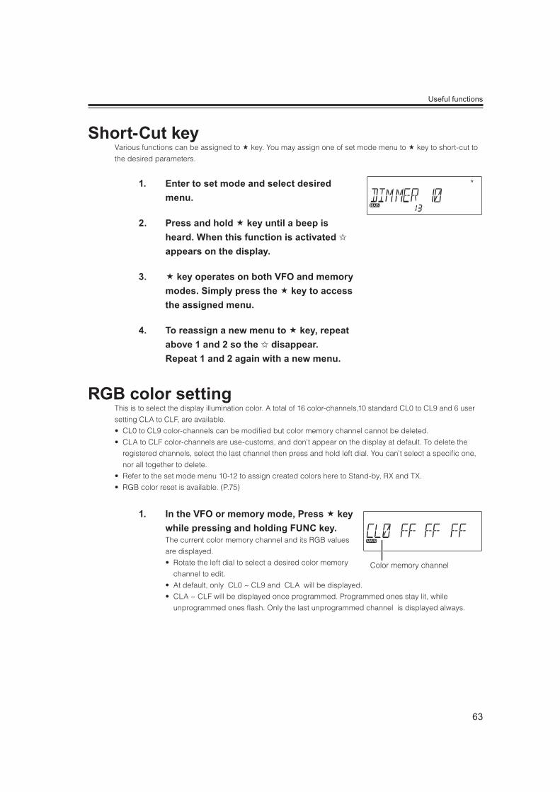
63
Useful functions
Various functions can be assigned to key. You may assign one of set mode menu to key to short-cut to
the desired parameters.
1. Enter to set mode and select desired menu.
2. Press and hold key until a beep is heard. When this function is activated ✩ appears on the display.
3. key operates on both VFO and memory modes. Simply press the key to access the assigned menu.
4. To reassign a new menu to key, repeat above 1 and 2 so the ✩ disappear.Repeat 1 and 2 again with a new menu.
This is to select the display illumination color. A total of 16 color-channels,10 standard CL0 to CL9 and 6 user
setting CLA to CLF, are available.
L0 to CL9 color-channels can be modified but color memory channel cannot be deleted.
LA to CLF color-channels are use-customs, and don’t appear on the display at default. To delete the
registered channels, select the last channel then press and hold left dial. You can’t select a specific one,
nor all together to delete.
efer to the set mode menu 10-12 to assign created colors here to Stand-by, RX and TX.
GB color reset is available. (P.75)
1. In the VFO or memory mode, Press key while pressing and holding FUNC key. The current color memory channel and its RGB values
are displayed.
otate the left dial to select a desired color memory
channel to edit.
t default, only CL0 ~ CL9 and CLA will be displayed.
LA ~ CLF will be displayed once programmed. Programmed ones stay lit, while
unprogrammed ones flash. Only the last unprogrammed channel is displayed always.
Color memory channel

64
Useful functions
2. Rotate the right dial or UP/DOWN keys to adjust RGB values as you like. Press the right dial to switch R,G and B parameters. The adjustable parameter ashes. The change affects immediately. The color is determined with the total combination of R,G and B value so changing only 1 value may not change the color drastically.
3. Press the left dial to save, press any key other than dials, UP/DOWN key to exit.When the new value is saved:
L0 ~ CL9 overwrites the old value.
lashing CLA ~ CLF channels will stay lit and
shows the programmed channels by rotating the dial.
To exit without saving , simply press FUNC key. A beep
is heard and returns to operating mode.
Detailed instruction will be available for downloads from
ALinco.com web site.

65
Useful functions
Many repeaters require a CTCSS tone or a DCS encode setting as a “key” to access a repeater system, or a
receiver using CTCSS or DCS squelch, so called “selective-calling”. Sometimes, CTCSS or DCS decode
features are used on the output of a repeater so they can be used to open a squelch. In this mode,
regardless of the main squelch status, the audio can be heard ONLY when the matching tone/code signal is
received. The combination of CTCSS squelch and DCS function is not available; only one or the other may
be used for given frequency.
1. In the VFO mode, set the operating band to MAIN. Press the FUNC key then press
key while [FUNC] appears on the display. The current tone frequency will be displayed. Repeat pressing key to select the setting mode as below:[T] CTCSS encoding: Transmits CTCSS encoding tone for repeater accesses.[T][SQL] CTCSS encoding and decoding tones. Tone squelch operation is possible.[DCS] DCS operation is possible. In DCS, both encoding and decoding tones are the same.Press any key except key to complete and return to operating mode. T/TSQL/DCS icons remains displayed.The same operation is possible in the memory mode
but temporary. Channel and power operation will delete
setting.
2. In above [T] , use Dial or UP/DOWN keys to select tone-encoding frequency. This value will apply automatically to the next decoding tone. In [TSQL], operating dial or UP/DOWN keys select the decoding frequency only. This is for a special application and conventional repeaters don’t require to separate encoding and decoding tones.
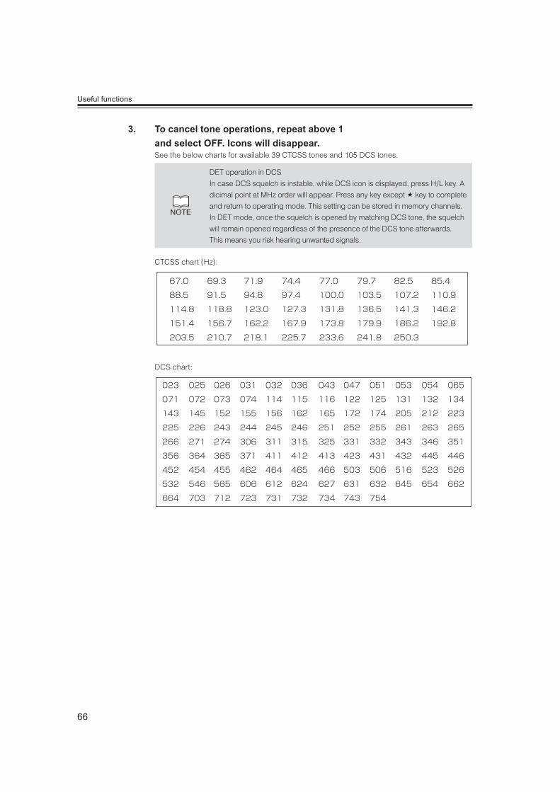
66
Useful functions
3. To cancel tone operations, repeat above 1 and select OFF. Icons will disappear.See the below charts for available 39 CTCSS tones and 105 DCS tones.
NOTE
DET operation in DCS
In case DCS squelch is instable, while DCS icon is displayed, press H/L key. A
dicimal point at MHz order will appear. Press any key except key to complete
and return to operating mode. This setting can be stored in memory channels.
In DET mode, once the squelch is opened by matching DCS tone, the squelch
will remain opened regardless of the presence of the DCS tone afterwards.
This means you risk hearing unwanted signals.
CTCSS chart (Hz):
67.0 69.3 71.9 74.4 77.0 79.7 82.5 85.4
88.5 91.5 94.8 97.4 100.0 103.5 107.2 110.9
114.8 118.8 123.0 127.3 131.8 136.5 141.3 146.2
151.4 156.7 162.2 167.9 173.8 179.9 186.2 192.8
203.5 210.7 218.1 225.7 233.6 241.8 250.3
DCS chart:
023 025 026 031 032 036 043 047 051 053 054 065
071 072 073 074 114 115 116 122 125 131 132 134
143 145 152 155 156 162 165 172 174 205 212 223
225 226 243 244 245 246 251 252 255 261 263 265
266 271 274 306 311 315 325 331 332 343 346 351
356 364 365 371 411 412 413 423 431 432 445 446
452 454 455 462 464 465 466 503 506 516 523 526
532 546 565 606 612 624 627 631 632 645 654 662
664 703 712 723 731 732 734 743 754

67
Useful functions
This function is used to transmit a memorized DTMF codes, up to 16 digits in available
characters (0 to 9/ABCD#*-). The autodialer memory should be set in advance to operate.
1. Press and hold FUNC key then press MW key.
2. Rotate left dial or press UP/DOWN keys to select an autodialer memory channel.
3. Rotate right dial to select a code, and push the right dial to save and move to edit next code. Press MW key to move left; the editing digit is displayed on the right beneath. Press and hold right dial to delete all codes.
4. Press any key other than PWR, or dials to save and exit.
NOTE pause is shown as [-] .
he shown codes will scroll toward left when excesses more than 6 digits.
1. Select Auto-dialer channel. Press and hold FUNC key then press MW key. Rotate left dial or UP/DOWN keys to select an autodialer memory channel.
2. While pressing and holding PTT, press UP key. Selected codes will be transmitted and the tones will be heard from the speaker.
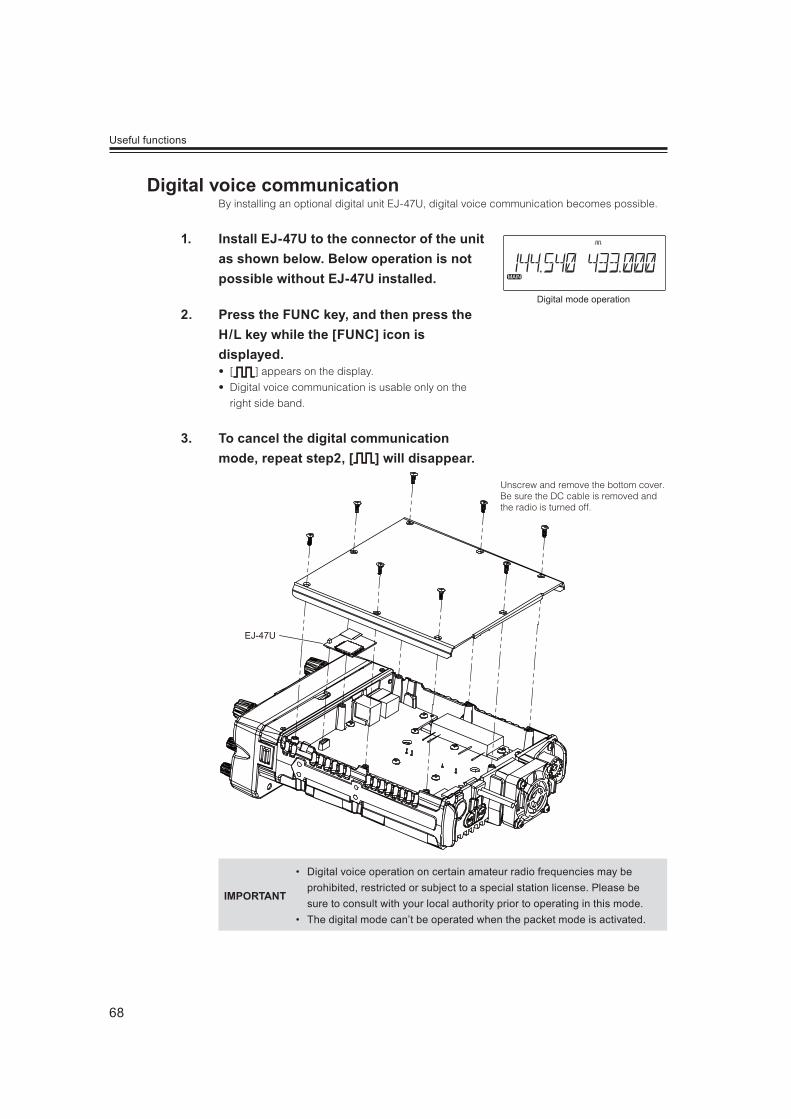
68
Useful functions
By installing an optional digital unit EJ-47U, digital voice communication becomes possible.
1. Install EJ-47U to the connector of the unit as shown below. Below operation is not possible without EJ-47U installed.
2. Press the FUNC key, and then press the H/L key while the [FUNC] icon is displayed. ] appears on the display.
igital voice communication is usable only on the
right side band.
3. To cancel the digital communication mode, repeat step2, [ ] will disappear.
EJ-47U
Unscrew and remove the bottom cover.Be sure the DC cable is removed and the radio is turned off.
IMPORTANT
Digital voice operation on certain amateur radio frequencies may be prohibited, restricted or subject to a special station license. Please be sure to consult with your local authority prior to operating in this mode.
The digital mode can’t be operated when the packet mode is activated.
Digital mode operation
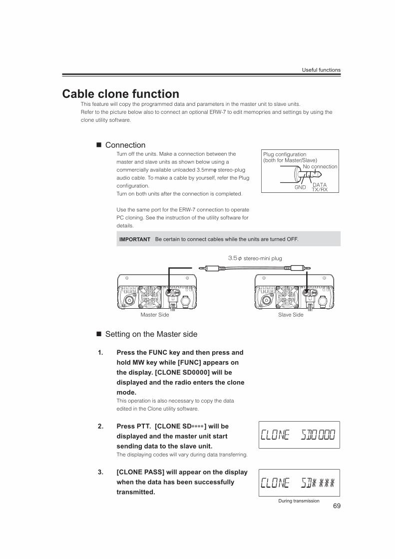
69
Useful functions
This feature will copy the programmed data and parameters in the master unit to slave units.
Refer to the picture below also to connect an optional ERW-7 to edit memopries and settings by using the
clone utility software.
ConnectionTurn off the units. Make a connection between the
master and slave units as shown below using a
commercially available unloaded 3.5mm stereo-plug
audio cable. To make a cable by yourself, refer the Plug
configuration.
Turn on both units after the connection is completed.
Use the same port for the ERW-7 connection to operate
PC cloning. See the instruction of the utility software for
details.
IMPORTANT Be certain to connect cables while the units are turned OFF.
stereo-mini plug
Slave SideMaster Side
Setting on the Master side
1. Press the FUNC key and then press and hold MW key while [FUNC] appears on the display. [CLONE SD0000] will be displayed and the radio enters the clone mode.This operation is also necessary to copy the data
edited in the Clone utility software.
2. Press PTT. [CLONE SD ] will be displayed and the master unit start sending data to the slave unit.The displaying codes will vary during data transferring.
3. [CLONE PASS] will appear on the display when the data has been successfully transmitted.
Plug configuration (both for Master/Slave)
No connection
During transmission

70
Useful functions
4. The master radio may stay turned on for the next clone. Turn off the unit to exit from the clone mode.
Setting on the slave side
1. Turn on and set to VFO or memory mode.
2. Operate the master side; [CLONE LD ] appears as it starts receiving the cloning data.
will change during data transferring.
3. When the transmission is successfully nished, [CLONE PASS] appears.
4. Turn off power. Disconnect the cable and repeat above to clone the next slave unit.If the data is not successfully transmitted, turn off both
units, make sure the cable connection is correct and
repeat the entire operation from beginning.
IMPORTANTNever disconnected the cable while data is being transmitted in the clone mode.It may cause damages to the radios.
When transmission is finished
During transmission
When transmission is finished
71
Useful functions
This mode allows the DR735T to operate like a repeater using both VHF and UHF bands.
That is, when receiving a signal on one band, the radio automatically transmits the same signal on another
band simultaneously.
Set the bands to145MHz and 440MHz, and select both frequencies within the transmitting range.
ny combination of VFO, memory channels, or CALL channels can be set as receiving and transmitting
frequencies provided they are 145/440MHz ham band combination.
he XBR doesn’t support digital modes such as packet and digital-voice.
he XBR respects the offset shift, direction and selective calling tone settings.
he TOT function is usable but TOT penalty-time and BCLO functions become deactivated during the
XBR operation.
hen the DC current is cut, and comes back again, the radio turns on in XBR mode without power key
operation.
To activate the XBR, turn off then press and hold the MW key while turning on the power.
XBR icons appear on the display. Repeat the same to exit from the XBR mode.
CAUTIONThe radio becomes very hot while operating as a XBR. Use of an external, additional
cooling fan is recommended especially when operating in high power.
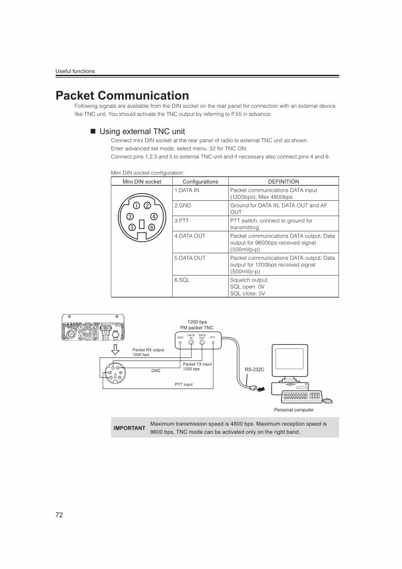
72
Useful functions
Following signals are available from the DIN socket on the rear panel for connection with an external device
like TNC unit. You should activate the TNC output by referring to P.55 in advance.
Using external TNC unitConnect mini DIN socket at the rear panel of radio to external TNC unit as shown.
Enter advanced set mode, select menu. 32 for TNC ON.
Connect pins 1,2,3 and 5 to external TNC unit and if necessary also connect pins 4 and 6.
Mini DIN socket configuration:
Mini DIN socket Con gurations DEFINITION1.DATA IN Packet communications DATA input
(1200bps), Max 4800bps
2.GND Ground for DATA IN, DATA OUT and AF OUT
3.PTT PTT switch, connect to ground for transmitting
4.DATA OUT Packet communications DATA output, Data output for 9600bps received signal (500mVp-p)
5.DATA OUT Packet communications DATA output, Data output for 1200bps received signal (500mVp-p)
6.SQL Squelch output. SQL open: 0VSQL close: 5V
RS-232C
1200 bpsFM packet TNC
GND
GND
PTT input
Packet RX output1200 bps
Packet TX input1200 bps
DATAIN
DATAOUT PTT
Personal computer
1
3 4
5 6
2
IMPORTANTMaximum transmission speed is 4800 bps. Maximum reception speed is 9600 bps. TNC mode can be activated only on the right band.
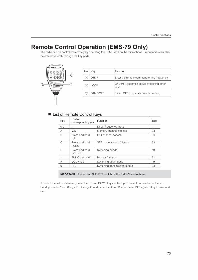
73
Useful functions
The radio can be controlled remotely by operating the DTMF keys on the microphone. Frequencies can also
be entered directly through the key pads.
No. Key Function
DTMF Enter the remote command or the frequency.
LOCKOnly PTT becomes active by locking other keys.
DTMF/OFF Select OFF to operate remote control,
List of Remote Control KeysKey Radio
corresponding key Function Page
0-9 - Direct frequency input −
A V/M Memory channel access 23
B Press and hold V/M
Call channel access 30
C Press and hold FUNC
SET mode access (Note1) 34
D Press and hold VOL Knob
Switching bands 19
* FUNC then MW Monitor function 31
# VOL Knob Switching MAIN band 19
0 H/L Switching transmission output 33
IMPORTANT There is no SUB PTT switch on the EMS-79 microphone.
To select the set mode menu, press the UP and DOWN keys at the top. To select parameters of the left
band, press the * and 0 keys. For the right band press the # and D keys. Press PTT key or C key to save and
exit.
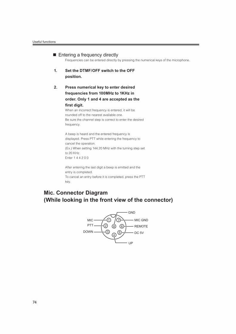
74
Useful functions
Entering a frequency directlyFrequencies can be entered directly by pressing the numerical keys of the microphone.
1. Set the DTMF/OFF switch to the OFF position.
2. Press numerical key to enter desired frequencies from 100MHz to 1KHz in order. Only 1 and 4 are accepted as the
rst digit.When an incorrect frequency is entered, it will be
rounded off to the nearest available one.
Be sure the channel step is correct to enter the desired
frequency.
A beep is heard and the entered frequency is
displayed. Press PTT while entering the frequency to
cancel the operation.
(Ex.) When setting 144.20 MHz with the turning step set
to 20 KHz.
Enter 1 4 4 2 0 0
After entering the last digit a beep is emitted and the
entry is completed.
To cancel an entry before it is completed, press the PTT
key.
MIC
GND
MIC GND
REMOTE
DC 5V
UP
1
2
34
5
6
7
8PTT
DOWN

75
Different reset features are available in DR-735. Please read carefully before you perform them. By using
restore function most setmode setting will be restored and recalled, but memory channel data are erased.
Use Clone utility to save the memory channel data.
This is to reset setting of VFO, setmode and advanced setmode parameters.
Most key operation functions will return to default conditions.
1. Turn on the radio by pressing PWR key while pressing FUNC key.
2. All segments of the LCD will be displayed and reset is completed.
This is to reset only VFO mode setting. All parameters in set mode and memory data will
remain.
1. Turn on the radio by pressing PWR key while pressing left V/M key.
2. All segments of the LCD will be displayed and VFO reset is completed.
This is to reset only memory data. All parameters in set mode and VFO frequency will remain.
1. Turn on the radio while pressing right V/M key.
2. INIT DATA will be displayed and memory reset is completed.
This is to reset user setting display color (CL0 ~ CL9, and to delete CLA ~ CLF channels).
1. Turn on the radio by pressing PWR key while pressing right V/M and key together.
2. All segments of the LCD will be displayed and RGB reset is completed.
This is to reset radio to factory default setting (except restored data in restore setting).
All above resets will be performed at once.
1. Turn on the radio by pressing PWR key while pressing MW, H/L and key together.
2. All segments of the LCD and INIT DATA will be displayed and All reset is completed.
All LCD segments
76
Maintenance / Reference
Please check the list below before concluding that the radio is faulty.
If a problem persists, reset the radio. This can sometimes correct erroneous operation.
Problem Possible Causes Potential SolutionsCan’t turn on the power.
a. + and – polarities of power connection are reversed.
a. Correctly connect the red lead and the black lead of the DC power cable respectively to the terminals.
b. Fuse is blown. b. Check and solve the problem resulting in blown fuse and replace it with a new one with the same rated capacity.
c. Power supply or DC/DC convertor is not turned on.
c. Turn on the power supply or DC/DC convertor.
Display is too dim. Dimmer setting level is low. Make the dimmer level setting higher.
No sound comes from the speaker. The unit does not receive.
a. Audio level is too low. a. Set the volume knob properly.b. Squelch is muted. b. Decreases squelch level.c. Tone or DCS squelch is active c. Turn tone or DCS squelch off.d. PTT key of the microphone is
pressed for transmission.d. Immediately release PTT switch.
e. External speaker is defective. e. Remove and inspect the speaker.
Keys and the dial do not function.
Key-lock function is activated ([ ] is on).
Cancel key-lock function.
Rotating the dial will not change memory channel.
a. No memory is programmed.b. The unit is in CALL mode.
a. Program memory channels.b. Press V/M key to cancel CALL mode.
Pressing the UP/DOWN key will not change frequencies or memory channels.
a. The unit is in CALL mode.b. Lock switch on the microphone is
ON.
a. Press V/M key to cancel CALL mode.b. Turn off the lock switch on the
microphone.
PTT pressed but doesn’t transmit.It transmits but can’t communicate.
a. Microphone terminal is not properly inserted.
b. Antenna is not connected.c. [OFF] appears on the display.
a. Properly insert the microphone connection.
b. Properly connect the antenna.c. Cancel SHIFT or set within the band.d. Transmit inside transmission range.
Noise hen reception frequencies fall in any one of the formula below, the unit may receive a
non-modulated signal.This is due to the structure of frequencies of this unit and not a malfunction.(Reception frequency on the left side VHF band – 21.7MHz) X 3 = UHF reception frequency on the right side)(Reception frequency on the left side UHF band – 21.7MHz) X 3 – (VHF reception frequency on the right side + 30.85MHz) X 7 = 30.85 MHz
hen reception frequency is 3 times bigger than transmission frequency, transmitted voice will be heard and [FREQ X3] appears on the display.
NOTE
Alinco guarantees the supply of minimum-necessary spare parts such as
microphones, components and mechanical parts for at least 5 years after
the production of this product is terminated except in case of accidents
beyond control.
Demonstration modeThis is for showcase purposes and display shows characters and different colors automatically. Turn the dial while in the demo mode to operate, and leave it for 10 minutes without operating to return to the demo mode. Key lock then turn off the power. Turn on with MW and H/L key pressed together to enter. Turn off the power in demo mode, turn on with MW and H/L key pressed together to exit.
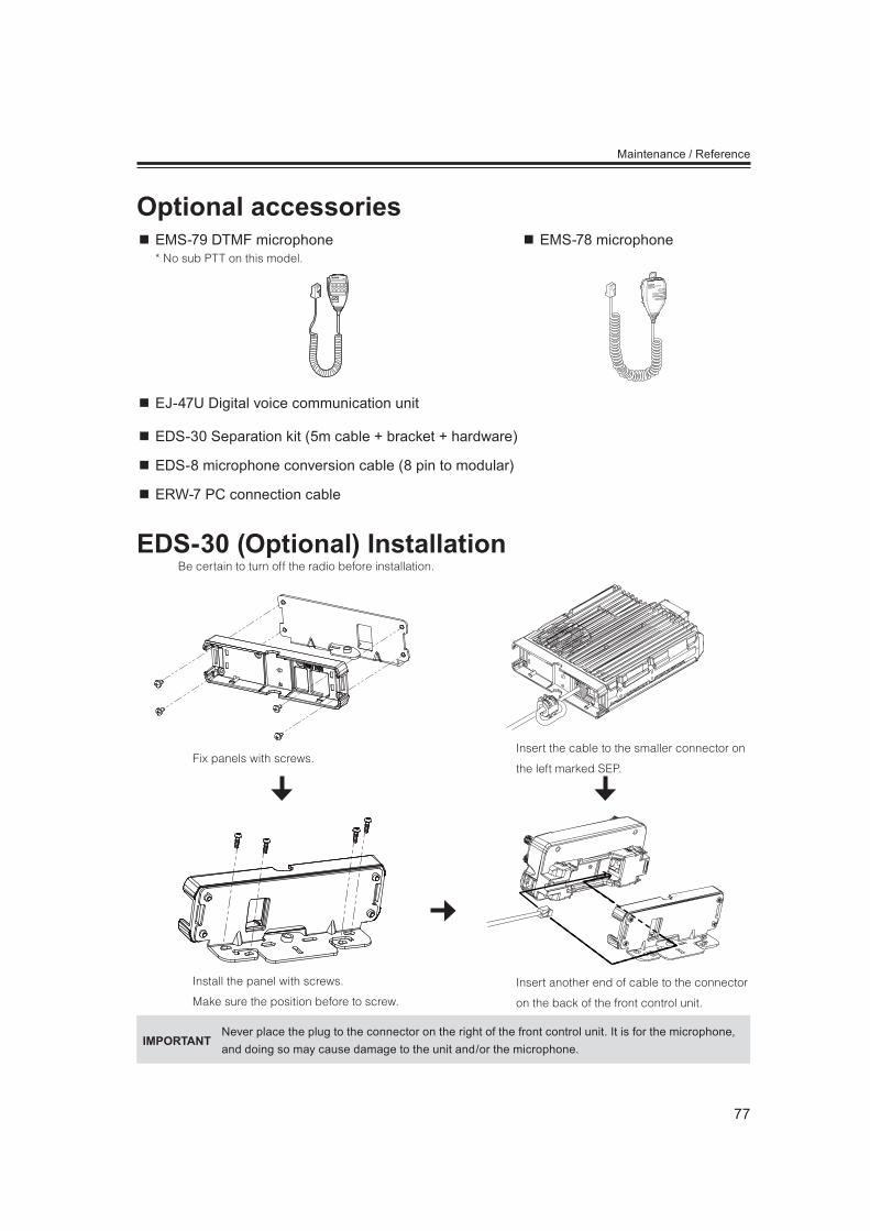
77
Maintenance / Reference
EMS-79 DTMF microphone* No sub PTT on this model.
EMS-78 microphone
EJ-47U Digital voice communication unit
EDS-30 Separation kit (5m cable + bracket + hardware)
EDS-8 microphone conversion cable (8 pin to modular)
ERW-7 PC connection cable
Be certain to turn off the radio before installation.
Fix panels with screws.Insert the cable to the smaller connector on
the left marked SEP.
Install the panel with screws.
Make sure the position before to screw.
Insert another end of cable to the connector
on the back of the front control unit.
IMPORTANTNever place the plug to the connector on the right of the front control unit. It is for the microphone,and doing so may cause damage to the unit and/or the microphone.

78
General
Frequency coverage
DR-735T
VHF
108.000 ~ 135.995MHz (RX)
136.000 ~ 173.995MHz (RX)
144.000 ~ 147.995MHz (TX)
UHF400.000 ~ 479.995MHz (RX)
430.000 ~ 449.995MHz (TX)
Frequency coverage
DR-735E
VHF
108.000 ~ 135.995MHz (RX)
136.000 ~ 173.995MHz (RX)
144.000 ~ 145.995MHz (TX)
UHF400.000 ~ 479.995MHz (RX)
430.000 ~ 439.995MHz (TX)
Operating mode16K0F3E (Normal mode)
8K50F3E (Narrow mode)
Frequency resolution 5, 6.25, 8.33, 10, 12.5, 15, 20, 25, 30, 50, 100KHz
Number of memory channels 1000ch+100ch(dual)
Antenna impedance 50 unbalanced
Power requirement 13.8V DC ±15% (11.7 to 15.8V)
Ground method Negative ground
Current drainReceive 0.6A (Max.) 0.4A (Squelched)
Transmit 12.0A
Operating temperature -10°C to 60°C
Frequency stability ±2.5ppm
Dimensions 140 (w)×Front: 60 Body: 40 (h)×188(d) mm
Weight Approx. 1.3kg
Transmitter
Output power High: 50W Mid : 20W Low : 5W
Modulation system Variable reactance frequency modulation
Maximum frequency deviation ±5kHz (Wide mode) ±2.5kHz (Narrow mode)
Spurious emission -60dB
Adjacent channel power -60dB
Noise and hum ratio -40dB (Wide mode) -34dB (Narrow mode)
Microphone impedance 2k
Receiver
Sensitivity -16dBu for 12dB SINAD
Receiver circuitry Double conversion super heterodyne
Intermediate
frequency
VHF MAIN
UHF SUB1st 21.7MHz 2nd 450kHz
UHF MAIN
VHF SUB1st 30.85MHz 2nd 455kHz
Squelch sensitivity -18dBu
Selectivity (-6dB/-60dB) 12kHz/24kHz
Inter modulation rejection ratio 60dB
Spurious and image rejection ratio 70dB
Audio output power >2.0W (8 ,10%THD)
All specifications are subject to change without notice or obligation.
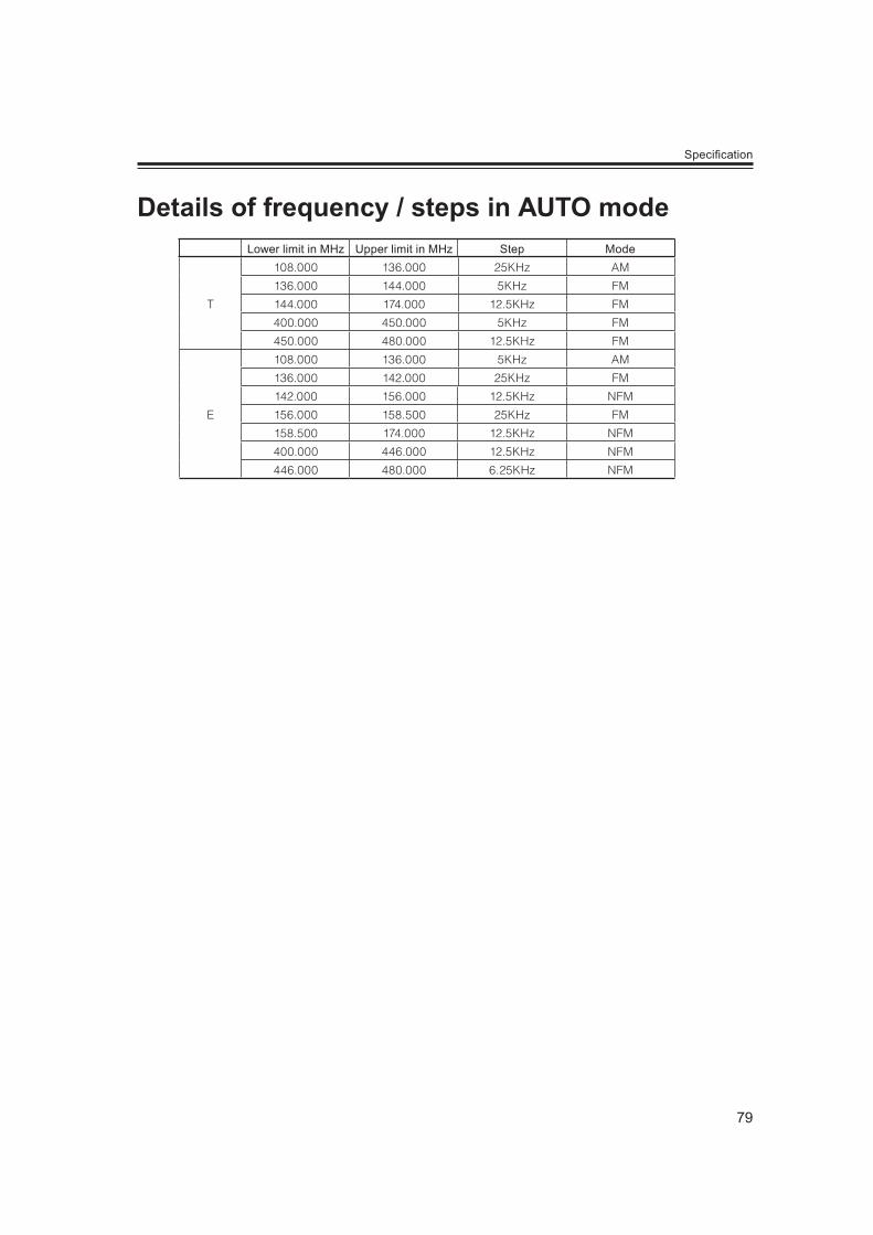
79
Speci cation
Lower limit in MHz Upper limit in MHz Step Mode
T
108.000 136.000 25KHz AM
136.000 144.000 5KHz FM
144.000 174.000 12.5KHz FM
400.000 450.000 5KHz FM
450.000 480.000 12.5KHz FM
E
108.000 136.000 5KHz AM
136.000 142.000 25KHz FM
142.000 156.000 12.5KHz NFM
156.000 158.500 25KHz FM
158.500 174.000 12.5KHz NFM
400.000 446.000 12.5KHz NFM
446.000 480.000 6.25KHz NFM

80
[MEMO]

81
[MEMO]

Printed in Philippines
ALINCO,INC. Head Of ce Yodoyabashi-Dai Building 13th Floor
4-9, 4-Chome, Koraibashi, Chuo-ku, Osaka 541-0043, Japan Phone +81-6-7636-2362 Fax +81-6-6208-3802 http //www.alinco.com/ E-mail export alinco.co.jp
Copyright Alinco, Inc. PS0867FNEJ-NH